EP3888947A1 - Fahrzeugluftreifen - Google Patents
Fahrzeugluftreifen Download PDFInfo
- Publication number
- EP3888947A1 EP3888947A1 EP20210725.6A EP20210725A EP3888947A1 EP 3888947 A1 EP3888947 A1 EP 3888947A1 EP 20210725 A EP20210725 A EP 20210725A EP 3888947 A1 EP3888947 A1 EP 3888947A1
- Authority
- EP
- European Patent Office
- Prior art keywords
- circumferential
- recess
- rib
- vehicle tire
- pneumatic vehicle
- Prior art date
- Legal status (The legal status is an assumption and is not a legal conclusion. Google has not performed a legal analysis and makes no representation as to the accuracy of the status listed.)
- Granted
Links
Images

Classifications
-
- B—PERFORMING OPERATIONS; TRANSPORTING
- B60—VEHICLES IN GENERAL
- B60C—VEHICLE TYRES; TYRE INFLATION; TYRE CHANGING; CONNECTING VALVES TO INFLATABLE ELASTIC BODIES IN GENERAL; DEVICES OR ARRANGEMENTS RELATED TO TYRES
- B60C11/00—Tyre tread bands; Tread patterns; Anti-skid inserts
- B60C11/03—Tread patterns
- B60C11/0318—Tread patterns irregular patterns with particular pitch sequence
-
- B—PERFORMING OPERATIONS; TRANSPORTING
- B60—VEHICLES IN GENERAL
- B60C—VEHICLE TYRES; TYRE INFLATION; TYRE CHANGING; CONNECTING VALVES TO INFLATABLE ELASTIC BODIES IN GENERAL; DEVICES OR ARRANGEMENTS RELATED TO TYRES
- B60C11/00—Tyre tread bands; Tread patterns; Anti-skid inserts
- B60C11/03—Tread patterns
- B60C11/0306—Patterns comprising block rows or discontinuous ribs
-
- B—PERFORMING OPERATIONS; TRANSPORTING
- B60—VEHICLES IN GENERAL
- B60C—VEHICLE TYRES; TYRE INFLATION; TYRE CHANGING; CONNECTING VALVES TO INFLATABLE ELASTIC BODIES IN GENERAL; DEVICES OR ARRANGEMENTS RELATED TO TYRES
- B60C11/00—Tyre tread bands; Tread patterns; Anti-skid inserts
- B60C11/03—Tread patterns
- B60C11/0306—Patterns comprising block rows or discontinuous ribs
- B60C11/0309—Patterns comprising block rows or discontinuous ribs further characterised by the groove cross-section
-
- B—PERFORMING OPERATIONS; TRANSPORTING
- B60—VEHICLES IN GENERAL
- B60C—VEHICLE TYRES; TYRE INFLATION; TYRE CHANGING; CONNECTING VALVES TO INFLATABLE ELASTIC BODIES IN GENERAL; DEVICES OR ARRANGEMENTS RELATED TO TYRES
- B60C11/00—Tyre tread bands; Tread patterns; Anti-skid inserts
- B60C11/03—Tread patterns
- B60C2011/0337—Tread patterns characterised by particular design features of the pattern
- B60C2011/0339—Grooves
- B60C2011/0341—Circumferential grooves
-
- B—PERFORMING OPERATIONS; TRANSPORTING
- B60—VEHICLES IN GENERAL
- B60C—VEHICLE TYRES; TYRE INFLATION; TYRE CHANGING; CONNECTING VALVES TO INFLATABLE ELASTIC BODIES IN GENERAL; DEVICES OR ARRANGEMENTS RELATED TO TYRES
- B60C11/00—Tyre tread bands; Tread patterns; Anti-skid inserts
- B60C11/03—Tread patterns
- B60C2011/0337—Tread patterns characterised by particular design features of the pattern
- B60C2011/0386—Continuous ribs
- B60C2011/039—Continuous ribs provided at the shoulder portion
-
- B—PERFORMING OPERATIONS; TRANSPORTING
- B60—VEHICLES IN GENERAL
- B60C—VEHICLE TYRES; TYRE INFLATION; TYRE CHANGING; CONNECTING VALVES TO INFLATABLE ELASTIC BODIES IN GENERAL; DEVICES OR ARRANGEMENTS RELATED TO TYRES
- B60C11/00—Tyre tread bands; Tread patterns; Anti-skid inserts
- B60C11/03—Tread patterns
- B60C11/13—Tread patterns characterised by the groove cross-section, e.g. for buttressing or preventing stone-trapping
- B60C11/1307—Tread patterns characterised by the groove cross-section, e.g. for buttressing or preventing stone-trapping with special features of the groove walls
- B60C2011/133—Tread patterns characterised by the groove cross-section, e.g. for buttressing or preventing stone-trapping with special features of the groove walls comprising recesses
-
- B—PERFORMING OPERATIONS; TRANSPORTING
- B60—VEHICLES IN GENERAL
- B60C—VEHICLE TYRES; TYRE INFLATION; TYRE CHANGING; CONNECTING VALVES TO INFLATABLE ELASTIC BODIES IN GENERAL; DEVICES OR ARRANGEMENTS RELATED TO TYRES
- B60C11/00—Tyre tread bands; Tread patterns; Anti-skid inserts
- B60C11/03—Tread patterns
- B60C11/13—Tread patterns characterised by the groove cross-section, e.g. for buttressing or preventing stone-trapping
- B60C11/1307—Tread patterns characterised by the groove cross-section, e.g. for buttressing or preventing stone-trapping with special features of the groove walls
- B60C2011/1338—Tread patterns characterised by the groove cross-section, e.g. for buttressing or preventing stone-trapping with special features of the groove walls comprising protrusions
Definitions
- the invention relates to a pneumatic vehicle tire with a tread with at least one profile rib delimited on at least one side by a circumferential groove that runs straight in plan view, which is composed of a sequence of at least two pitches with different circumferential lengths over the circumference of the tread and has a circumferential rib flank on the circumferential groove, wherein in each pitch on the rib flank at the profile rib periphery a circumferentially elongated recess is formed, which on the profile rib periphery has a shorter boundary edge and a longer boundary edge than this and which is bounded by two boundary surfaces adjoining the boundary edges and a bottom surface, the Boundary edges and the boundary surfaces in plan view each enclose an angle of 100 ° to 160 °.
- Such a pneumatic vehicle tire which is in particular a commercial vehicle tire, is, for example, from DE 10 2017 203 011 A1 known.
- the tread of this tire has two shoulder-side tread ribs which are each delimited by a circumferential groove that runs straight in plan view.
- recesses with a maximum circumferential length of 70% to 90% of the tread depth are formed in the profile rib periphery, the recesses being delimited by radially extending boundary surfaces and a bottom surface.
- One of the boundary surfaces extends in plan view to the axial direction at an angle of up to 35 °, the other boundary surface forms an angle of 90 ° to 125 ° with the first-mentioned boundary surface.
- the floor area is at a depth of 15% to 25% of the profile depth.
- the boundary surface running at an angle of up to 35 ° to the axial direction presented a Limiting edge that acts as a traction edge is available on the profile rib periphery.
- the second delimiting surface has a delimiting edge running essentially in the circumferential direction on the profile rib periphery. Together with the floor area, this should enable the profile rib to be stabilized.
- the invention is based on the object of protecting the circumferential groove in a pneumatic vehicle tire of the type mentioned at the outset from the penetration of stones, with good water absorption and water drainage properties being retained.
- the recess on the circumferential groove has a maximum circumferential length determined on the profile rib periphery of 70% to 100% of the circumferential length of the respective pitch, the longer delimiting edge of the recess in plan view to the circumferential direction at an angle of up to 8 ° and wherein a circumferentially elongated projection with a maximum circumferential length of 30% to 50% of the circumferential length of the respective pitch is formed radially inside the recess at a distance from this on the rib flank.
- the elongated projections formed in the recesses create a geometry that is stepped in cross section towards the periphery of the profile ribs ( Fig. 3 ), which on the one hand significantly reduces the possibility of stones penetrating into the circumferential groove in this area and on the other hand promotes the ejection of any stones trapped in this area. Furthermore, the projections block the movement of any stones that have penetrated the circumferential groove, so that the circumferential groove, in particular the groove base, is better protected from damage.
- the length of the recesses and the projections is matched to the circumferential length of the respective pitch, with the recesses being made significantly longer than the projections, so that good water absorption and water drainage properties are maintained.
- the longer delimiting edge has a circumferential length of at least 85%, in particular of at least 90%, of the maximum circumferential length of the recess. Since this boundary edge to the circumferential direction runs at an angle of up to 8 °, the recess is clearly elongated in the circumferential direction. This also improves the water drainage.
- the recess at its deepest point in the radial direction has a depth of at least 1.0 mm and a maximum of 25% of the profile depth, preferably of at least 15% of the profile depth.
- the bottom surface of the recess is inclined relative to the profile rib periphery in such a way that the recess has a depth continuously decreasing over its circumferential extent, determined in the radial direction, and ends at the end of the longer delimiting edge lying on the rib flank.
- the circumferential groove is additionally protected from intruding stones.
- the probability of stones getting caught in the circumferential groove is further reduced if the bottom surface of the recess with the boundary surface adjoining the longer boundary edge, viewed in the tire cross-section, encloses an angle of 90 ° ⁇ 3 °, in particular greater than 90 ° .
- the maximum circumferential length of the recess is preferably 80% to 95% of the circumferential length of the respective pitch.
- the desired properties or effects - namely water drainage and protection against stones - are particularly balanced when the angle at which the longer delimiting edge of the recess extends to the circumferential direction is up to 6 °, in particular 2 ° to 4 °.
- the angle at which the delimiting edges of the delimiting surfaces adjoin one another in plan view is 140 ° to 150 °.
- boundary surfaces viewed in the cross-section oriented perpendicular to the associated boundary edge, run in the radial direction or at an angle of up to 1.5 ° to this.
- boundary surfaces are favorable with regard to the ratio between the volume of the recess and the profile rib surface which is recessed on the profile rib periphery and which influences the net contact area of the tread to the roadway.
- the projection is located within a distance measured in the circumferential direction, which is determined based on the end of the shorter boundary edge on the rib flank and 60%, preferably 50%, of the circumferential length of the pitch amounts to.
- the projection is therefore located radially inside that end area of the recess at which the recess on the profile rib periphery has its greater width (see Fig Fig. 2 ).
- the projection has a thickness compared to the level of the rib flank which is 8% to 20%, in particular up to 15%, of the width of the circumferential groove.
- a groove area or groove section which is advantageously wide for water drainage in the circumferential groove, remains to the side of the projection.
- the length of the projection is 35% to 45% of the circumferential length of the associated pitch.
- the projection in relation to the lowest point of the circumferential groove in the radial direction at its highest point has a height of 45% to 75%, in particular from 57% to 70%, which has tread depth.
- the water drainage in the circumferential groove is further improved if the projection is limited in the circumferential directions by two, in particular, end faces running in the radial direction, which are inclined in opposite directions to one another to the axial direction and to this at preferably matching angles of 30 ° to 70 °, in particular of 40 ° to 50 °.
- Pneumatic vehicle tires designed according to the invention are tires for multi-lane motor vehicles and preferably radial tires for passenger cars, vans or light trucks.
- Fig. 1 shows a circumferential section of half of a tread with a shoulder-side tread rib 1, a middle tread rib 2, a tread rib 1 separating from the tread rib 2, straight in plan view circumferential groove 3 and a merely indicated central circumferential groove 4 running along the tire zenith, which the middle tread rib 2 limited to further profile structures of the tread.
- the tread is noise-optimized according to a method of pitch length variation and is made up of pitches that follow one another in the circumferential direction - of the same type designed profile sections - together, with the shoulder-side profile rib 1 having pitches L, M, K with three different circumferential lengths l L , l M , l K in the illustrated embodiment.
- Fig. 1 For example, a sequence of a pitch L with the greatest circumferential length l L , a pitch M with the circumferential length l M and a pitch K with the smallest circumferential length l K is provided, the pitch limits being indicated with dashed lines.
- the pitches L, M, K are arranged over the tread circumference within what is known as a pitch sequence, which is usually determined by calculation.
- the ratio of the three circumferential lengths l L : l M : l K is preferably selected in the usual range and is, for example, 1.4: 1.2: 1.0.
- the circumferential lengths l L , l M , l K are in particular in the range from 15 mm to 35 mm.
- the middle profile rib 2 is indicated schematically and can be provided with transverse grooves and / or incisions in a known manner.
- the shoulder-side profile rib 1 has block-like structures 1a, which by largely parallel to each other running transverse grooves 5, directly adjoining these transverse incisions 5 ', which end within the profile rib 1, and overall arcuate incisions 7, which in the circumferential direction within the profile rib 1 between the end portions of the transverse cuts 5 'extend and are spaced from the circumferential groove 3, are formed.
- a transverse groove 6, which is narrower than the transverse groove 5, and a cross-sectional cut 6 ′ adjoining this are formed.
- the circumferential groove 3 viewed in cross section, is bounded by a U-shaped rounded groove base 3a, to the middle profile rib 2 by a rib flank 3b and to the shoulder-side profile rib 1 by a rib flank 3c.
- the rib flanks 3b, 3c also viewed in the cross section of the circumferential groove 3, extend to the radial direction at an angle ⁇ of, for example, up to 15 °, preferably up to 10 °, or alternatively in the radial direction.
- the circumferential groove 3 is designed in the radial direction to the tread depth T 1 provided in each case, which for the preferred type of tire (car, van, light truck) is in particular 6.5 mm to 13.0 mm, and has its tread periphery narrowest points or sections in the axial Direction a width B 1 from 6.0 mm to 13.0 mm, in particular from 8.0 mm to 12.0 mm.
- Fig. 1 is on the shoulder-side profile rib 1 running along the rib flank 3c in each pitch L, M, K a protruding from the profile rib periphery into the shoulder-side profile rib 1, elongated in the circumferential direction and in the embodiment, essentially over the entire circumferential length l L , l M , l K des associated pitch L, M, K running, superficial recess 8 formed.
- a flat, plate-like projection 9 which is elongated in the circumferential direction and is connected to the groove base 3a and to the rib flank 3c (cf. FIGS. 3 and 4 ).
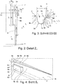
- FIG Figures 2 to 4 show the recess 8 located in the pitch K with the associated projection 9, explained in more detail.
- Some of the dimensions of the recess 8 and the projection 9 mentioned below are dependent on the circumferential length of the respective pitch.
- the dimensions below referring to the circumferential length l K of the pitch K apply in the two other pitches L, M for the circumferential lengths l L , l M belonging to these.
- the recess 8 viewed in the cross section of the circumferential groove 3, is essentially square.
- the recess 8 at the profile rib periphery has a shorter radially outer limiting edge 8a and a radially outer limiting edge 8b that is longer and less inclined to the circumferential direction than this (cf. Fig. 2 ), furthermore on the circumferential groove 3 a delimiting edge 8c running in the radial direction and a radially inner delimiting edge 8d which is longer than this and runs along the circumferential groove 3.
- Fig. 4 the recess 8 at the profile rib periphery has a shorter radially outer limiting edge 8a and a radially outer limiting edge 8b that is longer and less inclined to the circumferential direction than this (cf. Fig. 2 ), furthermore on the circumferential groove 3 a delimiting edge 8c running in the radial direction and a radially inner delimiting edge 8d which is longer than this and runs along the circumferential groove
- the radially outer delimiting edges 8a, 8b each end at the rib flank 3c, the longer radially outer delimiting edge 8b in the embodiment shown ending at the corresponding pitch limit, viewed in plan view, to the circumferential direction at an angle ⁇ of up to 8 °, in particular of up to 6 °, and preferably from 2 ° to 4 ° and with the shorter radially outer limiting edge 8a an angle ⁇ of 100 ° to 160 °, in particular from 140 ° to 150 °.
- the angle ⁇ of the longer radially outer limiting edge 8b and the angle ⁇ between the limiting edge 8a and 8b are coordinated such that the radially outer limiting edge 8a to the circumferential direction at an angle ⁇ of up to 65 °, preferably of up to 55 ° , runs.
- the boundary edge 8c running in the radial direction connects to the end of the shorter radially outer boundary edge 8a lying on the rib flank 3c and ends opposite the profile rib periphery at a depth t 1 determined in the radial direction, which is at least 1.0 mm and a maximum of 25% of the profile depth T 1 , preferably at least 15% of the profile depth T 1 (profile depth T 1 see Fig. 3 ).
- the longer, radially inner delimiting edge 8d running along the circumferential groove 3 adjoins the delimiting edge 8c at depth t 1 and, with a continuous reduction in its radial distance from the profile rib periphery, extends to the end of the longer radially outer delimiting edge 8b lying on the rib flank 3c.
- the recess 8 between the end of the shorter radially outer delimiting edge 8a lying on the circumferential groove 3 and the end of the longer radially outer delimiting edge 8b lying on the circumferential groove 3 has a maximum circumferential length l 1 of 70% to 100%, in particular 80 % to 95%, of the circumferential length l K of the pitch K.
- the longer radially outer delimiting edge 8b has a circumferential length l 1 ′ of at least 85%, in particular of at least 90%, of the maximum circumferential length l 1 of the recess 8.
- the recess 8 on the profile rib periphery at the mutual connection of the shorter radially outer delimiting edge 8a and the longer radially outer delimiting edge 8b has its widest point, determined in the axial direction, with the width b 1 .
- the mentioned angles ⁇ and ⁇ , the maximum circumferential length l 1 of the recess 8 and the circumferential length l 1 'of the longer radially outer delimiting edge 8b are preferably matched to one another such that the width b 1 of the recess 8 is 1.5 mm to 3.5 mm amounts to.
- the recess 8 is formed by a substantially rectangular delimiting surface 8a 'adjoining the shorter radially outer delimiting edge 8a and the delimiting edge 8c running in the radial direction, a triangular delimiting surface 8b' extending along the longer radially outer delimiting edge 8b and elongated in the circumferential direction. and a triangular bottom surface 8d 'which extends along the radially inner delimiting edge 8d and is elongated in the circumferential direction.
- the essentially rectangular delimiting surface 8a 'and the triangular delimiting surface 8b' are, viewed in cross section perpendicular to the associated radially outer delimiting edge 8a, 8b, oriented in the radial direction or at an angle of up to 1.5 ° to this (for delimiting surface 8b ' please refer Fig. 3 ).
- the bottom surface 8d ' forms an angle ⁇ of 90 ° ⁇ 3 °, in particular greater than 90 °, when viewed in the tire cross-section with the triangular boundary surface 8b' ( Fig. 3 ).
- the radially inner delimiting edge 8d and the longer radially outer delimiting edge 8b adjoin one another at the profile rib periphery, so that the bottom surface 8d 'is inclined relative to the profile rib periphery and the recesses 8 - each starting from the essentially rectangular delimiting surface 8a' - a have continuously decreasing depth along the radially inner delimiting edge 8d and a cross-sectional area (cross-section aligned in the axial direction) that decreases continuously along the longer radially outer delimiting edge 8b.
- the already mentioned flat plate-like projection 9, formed radially inside the recess 8, is located within a distance a 1 measured in the circumferential direction, which is determined starting from the end of the shorter radially outer boundary edge 8a located on the rib flank 3c and 60%, preferably 50 %, the circumferential length l K of the pitch K is.
- the projection 9 has a thickness s 2 determined in relation to and perpendicular to the level of the rib flank 3c ( Fig. 3 ) from 8% to 20%, in particular up to 15%, of the B 1 of the circumferential groove 3, a maximum length l 2 determined at the level of the rib flank 3c and in the circumferential direction ( Fig. 2 ) from 30% to 50%, in particular from 35% to 45%, of the circumferential length l K of the pitch K and a height h 2 ( Fig. 3 ) from 45% to 75%, in particular from 57% to 70% of the profile depth T 1 .
- the projection 9 is at the height h 2 ( Fig.
- a trapezoidal top surface 9a running parallel to the tread periphery, axially laterally by a side surface 9b oriented parallel to the rib flank 3c ( Fig. 3 ) and in the circumferential directions by two radial end faces 9c ( Fig. 2, Fig. 4 ) limited.
- the end faces 9c are inclined to one another in opposite directions to the axial direction and extend to this at preferably matching angles ⁇ of 30 ° to 70 °, in particular from 40 ° to 50 °.
- the recesses and projections described can also be formed on rib flanks of central profile ribs.
- the profile ribs, on the rib flanks of which the recesses and projections are provided do not have any incisions and transverse grooves which emerge on the rib flank having the recesses and projections.
- the profile rib has incisions and / or grooves which end from the rib flank having the recesses and projections.
- the edges of the projections can be provided with chamfers (inclined surfaces) with a width of in particular up to 1.0 mm.
- the top surface of the projections can be inclined to the radial direction at an angle of up to 25 °.
- the projections are preferably provided with transition curves which run to the rib flank and the groove base.
Landscapes
- Engineering & Computer Science (AREA)
- Mechanical Engineering (AREA)
- Tires In General (AREA)
Abstract
Description
- Die Erfindung betrifft einen Fahrzeugluftreifen mit einem Laufstreifen mit zumindest einer an zumindest einer Seite von einer in Draufsicht gerade verlaufenden Umfangsrille begrenzten Profilrippe, welche sich über den Laufstreifenumfang aus einer Abfolge von zumindest zwei Pitches mit unterschiedlichen Umfangslängen zusammensetzt und an der Umfangsrille eine umlaufende Rippenflanke aufweist, wobei in jedem Pitch an der Rippenflanke bei der Profilrippenperipherie eine in Umfangsrichtung langgestreckte Ausnehmung ausgebildet ist, welche an der Profilrippenperipherie jeweils eine kürzere Begrenzungskante und eine gegenüber dieser längere Begrenzungskante aufweist und welche durch zwei an die Begrenzungskanten anschließende Begrenzungsflächen und eine Bodenfläche begrenzt ist, wobei die Begrenzungskanten und die Begrenzungsflächen in Draufsicht jeweils einen Winkel von 100° bis 160° einschließen.
- Ein derartiger Fahrzeugluftreifen, welcher insbesondere ein Nutzfahrzeugreifen ist, ist beispielsweise aus der
DE 10 2017 203 011 A1 bekannt. Der Laufstreifen dieses Reifens weist zwei schulterseitige Profilrippen auf, welche jeweils durch eine in Draufsicht gerade verlaufende Umfangsrille begrenzt sind. An den Rippenflanken der Umfangsrille sind bei der Profilrippenperipherie Ausnehmungen mit einer maximalen Umfangslänge von 70% bis 90% der Profiltiefe ausgebildet, wobei die Ausnehmungen von in Draufsicht L-förmig zueinander verlaufenden, sich in radialer Richtung erstreckenden Begrenzungsflächen und einer Bodenfläche begrenzt sind. Die eine der Begrenzungsflächen verläuft in Draufsicht zur axialen Richtung unter einem Winkel von bis zu 35°, die andere Begrenzungsfläche schließt mit der erstgenannten Begrenzungsfläche einen Winkel von 90° bis 125° ein. Die Bodenfläche befindet sich in einer Tiefe von 15% bis 25% der Profiltiefe. Die zur axialen Richtung unter einem Winkel von bis zu 35° verlaufende Begrenzungsfläche stellte eine als Traktionskante wirkende Begrenzungskante an der Profilrippenperipherie zur Verfügung. Die zweite Begrenzungsfläche weist an der Profilrippenperipherie eine im Wesentlichen in Umfangsrichtung verlaufende Begrenzungskante auf. Diese soll gemeinsam mit der Bodenfläche eine Stabilisierung der Profilrippe ermöglichen. - Der Erfindung liegt die Aufgabe zugrunde, bei einem Fahrzeugluftreifen der eingangs genannten Art die Umfangsrille vor eindringenden Steinen zu schützen, wobei gute Wasseraufnahme- und Wasserdrainageeigenschaften erhalten bleiben sollen.
- Gelöst wird die gestellte Aufgabe erfindungsgemäß dadurch, dass die Ausnehmung an der Umfangsrille eine an der Profilrippenperipherie ermittelte maximale Umfangslänge von 70% bis 100% der Umfangslänge des jeweiligen Pitch aufweist, wobei die längere Begrenzungskante der Ausnehmung in Draufsicht zur Umfangsrichtung unter einem Winkel von bis zu 8° verläuft und wobei radial innerhalb der Ausnehmung in einem Abstand zu dieser an der Rippenflanke ein in Umfangsrichtung langgestreckter Vorsprung mit einer maximalen Umfangslänge von 30% bis 50% der Umfangslänge des jeweiligen Pitch ausbildet ist.
- Durch die bei den Ausnehmungen ausgebildeten, langgestreckten Vorsprünge ist eine im Querschnitt stufenförmige Geometrie zur Profilrippenperipherie gebildet (
Fig. 3 ), welche einerseits die Möglichkeit, dass Steine in diesem Bereich in die Umfangsrille eindringen deutlich verringert und andererseits den Auswurf von etwaigen in diesem Bereich eingefangenen Steinen fördert. Ferner blockieren die Vorsprünge die Fortbewegung von etwaigen in die Umfangsrille eingedrungenen Steinen, sodass die Umfangsrille, insbesondere der Rillengrund, vor Schäden besser geschützt ist. Die Länge der Ausnehmungen und der Vorsprünge ist auf die Umfangslänge des jeweiligen Pitch abgestimmt, wobei die Ausnehmungen deutlich länger als die Vorsprünge ausgeführt sind, wodurch gute Wasseraufnahme- und Wasserdrainageeigenschaften erhalten bleiben. - Gemäß einer bevorzugten Ausführung weist die längere Begrenzungskante eine Umfangslänge von zumindest 85%, insbesondere von zumindest 90%, der maximalen Umfangslänge der Ausnehmung auf. Da diese Begrenzungskante zur Umfangsrichtung unter einem Winkel von bis zu 8° verläuft, ist die Ausnehmung in Umfangsrichtung deutlich langgestreckt. Dies verbessert zusätzlich die Wasserdrainage.
- Die Möglichkeit, dass Steine in die Umfangsrille eindringen, ist weiter verringert, wenn die Ausnehmung, ermittelt gegenüber dem Niveau der Rippenflanke am gegenseitigen Anschluss ihrer Begrenzungskanten, in axialer Richtung eine Breite von 1,5 mm bis 3,5 mm aufweist.
- Es ist vor allem für die Wasserdrainage von Vorteil, wenn die Ausnehmung an ihrer tiefsten Stelle in radialer Richtung eine Tiefe von mindestens 1,0 mm und maximal 25% der Profiltiefe, vorzugsweise von mindestens 15% der Profiltiefe, aufweist.
- Gemäß einer weiteren bevorzugten Ausführung ist die Bodenfläche der Ausnehmung derart relativ zur Profilrippenperipherie geneigt, dass die Ausnehmung eine über ihre Umfangserstreckung kontinuierlich abnehmende, in radialer Richtung ermittelte Tiefe aufweist und am an der Rippenflanke liegenden Ende der längeren Begrenzungskante ausläuft. Dadurch die Umfangsrille vor eindringenden Steinen zusätzlich geschützt.
- Insbesondere ist die Wahrscheinlichkeit, dass sich in der Umfangsrille Steine verfangen, weiter reduziert, wenn die Bodenfläche der Ausnehmung mit der an die längere Begrenzungskante anschließenden Begrenzungsfläche, im Reifenquerschnitt betrachtet, einen Winkel von 90°± 3°, insbesondere von größer 90°, einschließt.
- Bevorzugter Weise beträgt die maximale Umfangslänge der Ausnehmung 80% bis 95% der Umfangslänge des jeweiligen Pitch.
- Die gewünschten Eigenschaften bzw. Effekte - nämlich die Wasserdrainage und der Schutz vor Steinen - sind besonders ausgewogen, wenn der Winkel, unter welchem die längere Begrenzungskante der Ausnehmung zur Umfangsrichtung verläuft, bis zu 6°, insbesondere 2° bis 4°, beträgt.
- Gemäß einer weiteren bevorzugten Ausführung beträgt der Winkel, unter welchem die Begrenzungskanten der Begrenzungsflächen in Draufsicht aneinander anschließen, 140° bis 150°.
- Ferner ist es bevorzugt, wenn die Begrenzungsflächen, im senkrecht zur zugehörigen Begrenzungskante ausgerichteten Querschnitt betrachtet, in radialer Richtung oder zu dieser unter einem Winkel von bis zu 1,5° verlaufen. Solche Begrenzungsflächen sind im Hinblick auf das Verhältnis zwischen dem Volumen der Ausnehmung und der an der Profilrippenperipherie ausgesparten Profilrippenoberfläche, welche die Netto-Kontaktfläche des Laufstreifen zur Fahrbahn beeinflusst, günstig.
- Für die Wasserdrainage in der Umfangsrille ist es von zusätzlichem Vorteil, wenn sich der Vorsprung innerhalb eines in Umfangsrichtung gemessenen Abstandes befindet, welcher ausgehend von dem an der Rippenflanke liegenden Ende der kürzeren Begrenzungskante ermittelt ist und 60%, bevorzugt 50%, der Umfangslänge des Pitch beträgt. Der Vorsprung befindet sich daher radial innerhalb jenes Endbereiches der Ausnehmung, an welchem die Ausnehmung an der Profilrippenperipherie ihre größere Breite aufweist (siehe
Fig. 2 ). - Für die gewünschten Eigenschaften bzw. Effekte (Wasserdrainage und Schutz vor Steinen) ist es ferner günstig, wenn der Vorsprung gegenüber dem Niveau der Rippenflanke eine Stärke aufweist, welche 8% bis 20%, insbesondere bis 15%, der Breite der Umfangsrille beträgt. Insbesondere bleibt dabei seitlich des Vorsprunges ein für die Wasserdrainage in der Umfangsrille vorteilhaft breiter Rillenbereich bzw. Rillenabschnitt vorhanden.
- Gemäß einer weiteren bevorzugten Ausführung beträgt die Länge des Vorsprunges 35% bis 45% der Umfangslänge des zugehörigen Pitch.
- Außerdem ist es für die gewünschten Eigenschaften bzw. Effekte (Wasserdrainage und Schutz vor Steinen) von Vorteil, wenn der Vorsprung gegenüber dem tiefsten Punkt der Umfangrille in radialer Richtung an seiner höchsten Stelle eine Höhe von 45% bis 75%, insbesondere von 57% bis 70%, der Profiltiefe aufweist.
- Die Wasserdrainage in der Umfangsrille ist weiter verbessert, wenn der Vorsprung in den Umfangsrichtungen durch zwei insbesondere in radialer Richtung verlaufende Stirnflächen begrenzt ist, welche zur axialen Richtung gegensinnig zueinander schräggestellt sind und zu dieser unter vorzugsweise übereinstimmenden Winkel von 30° bis 70°, insbesondere von 40° bis 50°, verlaufen.
- Weitere Merkmale, Vorteile und Einzelheiten der Erfindung werden nun anhand der Zeichnung, die schematisch ein Ausführungsbeispiel der Erfindung zeigt, näher beschrieben. Dabei zeigen
-
Fig. 1 eine Draufsicht auf einen Ausschnitt eine Laufstreifens eines Fahrzeugluftreifens mit einer Ausführungsvariante der Erfindung, -
Fig. 2 eine vergrößerte Draufsicht auf das Detail Z2 des Laufstreifens ausFig. 1 , -
Fig. 3 einen Schnitt entlang der Linie III-III derFig. 2 und -
Fig. 4 eine Schrägansicht gemäß der durch den Pfeil S4 inFig. 2 angedeuteten Sichtrichtung. - Gemäß der Erfindung ausgeführte Fahrzeugluftreifen sind Reifen für mehrspurige Kraftfahrzeuge sowie vorzugsweise Reifen in Radialbauart für Personenkraftwagen, Vans oder Light-Trucks.
-
Fig. 1 zeigt einen Umfangsabschnitt der Hälfte eines Laufstreifens mit einer schulterseitigen Profilrippe 1, einer mittleren Profilrippe 2, einer die Profilrippe 1 von der Profilrippe 2 trennenden, in Draufsicht gerade verlaufenden Umfangsrille 3 und einer lediglich angedeuteten entlang des Reifenzenits verlaufenden zentralen Umfangsrille 4, welche die mittlere Profilrippe 2 zu weiteren Profilstrukturen des Laufstreifens begrenzt. - Der Laufstreifen ist gemäß einem Verfahren der Pitchlängenvariation geräuschoptimiert und setzt sich aus in Umfangsrichtung aufeinanderfolgenden Pitches - gleichartig gestalteten Profilabschnitten - zusammen, wobei beim gezeigten Ausführungsbeispiel die schulterseitige Profilrippe 1 Pitches L, M, K mit drei unterschiedlichen Umfangslängen lL, lM, lK aufweist. In
Fig. 1 ist beispielhaft eine Aufeinanderfolge eines Pitch L mit der größten Umfangslänge lL, eines Pitch M mit der Umfangslänge lM und eines Pitch K mit der kleinsten Umfangslänge lK vorgesehen, wobei die Pitchgrenzen mit gestrichelten Linien angedeutet sind. Die Pitches L, M, K werden über den Laufstreifenumfang innerhalb einer sogenannten Pitchfolge, die üblicherweise rechnerisch ermittelt wird, angeordnet. Das Verhältnis der drei Umfangslängen lL : lM : lK ist vorzugsweise im üblichen Bereich gewählt und beträgt beispielsweise 1,4 : 1,2 : 1,0. Die Umfangslängen lL, lM, lK liegen insbesondere im Bereich von 15 mm bis 35 mm. - Die mittlere Profilrippe 2 ist schematisch angedeutet und kann in bekannter Weise mit Querrillen und/oder Einschnitte versehen sein. Die schulterseitige Profilrippe 1 weist blockartige Strukturen 1a auf, welche durch weitgehend parallel zueinander verlaufende Querrillen 5, an diese jeweils unmittelbar anschließende Quereinschnitte 5', welche innerhalb der Profilrippe 1 enden, und insgesamt bogenförmig verlaufende Einschnitte 7, welche in Umfangsrichtung innerhalb der Profilrippe 1 zwischen den Endabschnitten der Quereinschnitte 5' verlaufen und von der Umfangsrille 3 beabstandet sind, gebildet sind. In jeder blockartigen Struktur 1a ist eine gegenüber der Querrille 5 schmäler ausgeführte Querrille 6 und ein an dieser anschließender Querschnittschnitt 6' ausgebildet. In jedem Pitch L, M, K befinden sich in der schulterseitigen Profilrippe 1 eine Querrille 5 und eine Querrille 6.
- Gemäß
Fig. 3 ist die Umfangsrille 3, im Querschnitt betrachtet, durch einen U-förmig gerundeten Rillengrund 3a, zur mittleren Profilrippe 2 durch eine Rippenflanke 3b und zur schulterseitigen Profilrippe 1 durch eine Rippenflanke 3c begrenzt. Die Rippenflanken 3b, 3c verlaufen, ebenfalls im Querschnitt der Umfangsrille 3 betrachtet, zur radialen Richtung jeweils unter einem Winkel α von beispielsweise bis zu 15°, vorzugsweise von bis zu 10°, oder alternativ in radialer Richtung. Die Umfangsrille 3 ist in radialer Richtung auf die jeweils vorgesehene Profiltiefe T1 ausgeführt, welche für den bevorzugt vorgesehenen Reifentyp (PKW, Van, Light-Truck) insbesondere 6,5 mm bis 13,0 mm beträgt, und weist an der Laufstreifenperipherie an ihren schmälsten Stellen bzw. Abschnitten in axialer Richtung eine Breite B1 von 6,0 mm bis 13,0 mm, insbesondere von 8,0 mm bis 12,0 mm, auf. - Gemäß
Fig. 1 ist an der die schulterseitige Profilrippe 1 entlangverlaufenden Rippenflanke 3c in jedem Pitch L, M, K eine von der Profilrippenperipherie in die schulterseitige Profilrippe 1 hineinragende, in Umfangsrichtung langgestreckte und beim Ausführungsbeispiel im Wesentlichen über die gesamte Umfangslänge lL, lM, lK des zugehörigen Pitch L, M, K verlaufende, oberflächliche Ausnehmung 8 ausgebildet. Radial innerhalb jeder Ausnehmung 8 befindet sich in einem Abstand zur Ausnehmung 8 ein in Umfangsrichtung langgestreckter, am Rillengrund 3a und an der Rippenflanke 3c angebundener flacher, plattenartiger Vorsprung 9 (vergleicheFig. 3 und Fig. 4 ). - Die weitere Ausgestaltung der Ausnehmungen 8 und der Vorsprünge 9 wird nachfolgend anhand der
Figuren 2 bis 4 , welche die im Pitch K befindliche Ausnehmung 8 mit zugehörigem Vorsprung 9 zeigen, näher erläutert. Einige der im Anschluss erwähnten Abmessungen der Ausnehmung 8 und des Vorsprunges 9 sind von der Umfangslänge des jeweiligen Pitch abhängig. Die nachfolgend jeweils auf die Umfangslänge lK des Pitch K bezugnehmenden Abmessungen gelten in den beiden anderen Pitches L, M für die zu diesen gehörenden Umfangslängen lL, lM. - Wie
Fig. 3 zeigt, ist die Ausnehmung 8, im Querschnitt der Umfangsrille 3 betrachtet, im Wesentlichen quadratisch ausgeführt. GemäßFig. 4 weist die Ausnehmung 8 an der Profilrippenperipherie eine kürzere radial äußere Begrenzungskante 8a und eine gegenüber dieser längere und zur Umfangsrichtung geringer geneigte radial äußere Begrenzungskante 8b (vergleicheFig. 2 ), ferner an der Umfangsrille 3 eine in radialer Richtung verlaufende Begrenzungskante 8c und eine gegenüber dieser längere, die Umfangsrille 3 entlangverlaufende radial innere Begrenzungskante 8d auf. GemäßFig. 2 enden die radial äußeren Begrenzungskanten 8a, 8b jeweils an der Rippenflanke 3c, wobei die längere radial äußere Begrenzungskante 8b beim gezeigten Ausführungsbeispiel an der entsprechenden Pitchgrenze endet, in Draufsicht betrachtet, zur Umfangsrichtung unter einem Winkel β von bis zu 8°, insbesondere von bis zu 6°, und bevorzugt von 2° bis 4° verläuft und mit der kürzeren radial äußeren Begrenzungskante 8a einen Winkel γ von 100° bis 160°, insbesondere von 140° bis 150°, einschließt. Bevorzugter Weise sind der Winkel β der längeren radial äußere Begrenzungskante 8b und der Winkel γ zwischen den Begrenzungskante 8a und 8b derart aufeinander abgestimmt, dass die radial äußere Begrenzungskante 8a zur Umfangsrichtung unter einem Winkel δ von bis zu 65°, vorzugsweise von bis zu 55°, verläuft. GemäßFig. 4 schließt die in radialer Richtung verlaufende Begrenzungskante 8c an das an der Rippenflanke 3c liegende Ende der kürzeren radial äußeren Begrenzungskante 8a an und endet gegenüber der Profilrippenperipherie in einer in radialer Richtung ermittelten Tiefe t1, welche mindestens 1,0 mm und maximal 25% der Profiltiefe T1, vorzugsweise mindestens 15% der Profiltiefe T1, beträgt (Profiltiefe T1 sieheFig. 3 ). Die längere, die Umfangsrille 3 entlangverlaufende radial innere Begrenzungskante 8d schließt in der Tiefe t1 an die Begrenzungskante 8c an und verläuft unter kontinuierlicher Verringerung ihres radialen Abstandes zur Profilrippenperipherie zum an der Rippenflanke 3c liegenden Ende der längeren radial äußeren Begrenzungskante 8b. - Wie
Fig. 2 ferner zeigt, weist die Ausnehmung 8 zwischen dem an der Umfangsrille 3 liegenden Ende der kürzeren radial äußere Begrenzungskante 8a und dem an der Umfangsrille 3 liegenden Ende der längeren radial äußeren Begrenzungskante 8b eine maximale Umfangslänge l1 von 70% bis 100%, insbesondere von 80% bis 95%, der Umfangslänge lK des Pitch K auf. Die längere radial äußere Begrenzungskante 8b weist eine Umfangslänge l1' von zumindest 85%, insbesondere von zumindest 90%, der maximalen Umfangslänge l1 der Ausnehmung 8 auf. - Ferner weist die Ausnehmung 8 an der Profilrippenperipherie am gegenseitigen Anschluss der kürzeren radial äußeren Begrenzungskante 8a und der längeren radial äußeren Begrenzungskante 8b ihre in axialer Richtung ermittelte breiteste Stelle mit der Breite b1 auf. Die erwähnten Winkel β und γ, die maximale Umfangslänge l1 der Ausnehmung 8 und die Umfangslänge l1' der längeren radial äußeren Begrenzungskante 8b sind vorzugsweise derart aufeinander abgestimmt, dass die Breite b1 der Ausnehmung 8 1,5 mm bis 3,5 mm beträgt.
- Wie
Fig. 4 ferner zeigt, ist die Ausnehmung 8 durch eine an die kürzere radial äußere Begrenzungskante 8a und die in radialer Richtung verlaufende Begrenzungskante 8c anschließende, im Wesentlichen rechteckige Begrenzungsfläche 8a', eine die längere radial äußere Begrenzungskante 8b entlangverlaufende, in Umfangsrichtung langgezogene, dreieckige Begrenzungsfläche 8b' und eine die radial innere Begrenzungskante 8d entlangverlaufende, in Umfangsrichtung langgezogene, dreieckige Bodenfläche 8d' begrenzt. Die im Wesentlichen rechteckige Begrenzungsfläche 8a' und die dreieckige Begrenzungsfläche 8b' sind, im Querschnitt senkrecht zur zugehörigen radial äußere Begrenzungskante 8a, 8b betrachtet, in radialer Richtung bzw. zu dieser unter einem Winkel von bis zu 1,5° orientiert (für Begrenzungsfläche 8b' sieheFig. 3 ). Die Bodenfläche 8d' schließt mit der dreieckige Begrenzungsfläche 8b' im Reifenquerschnitt betrachtet einen Winkel ε von 90°± 3°, insbesondere von größer 90°, ein (Fig. 3 ). Wie bereits erläutert, schließen die radial innere Begrenzungskante 8d und die längere radial äußere Begrenzungskante 8b an der Profilrippenperipherie aneinander an, sodass die Bodenfläche 8d' relativ zur Profilrippenperipherie geneigt ist und die Ausnehmungen 8 - jeweils ausgehend von der im Wesentlichen rechteckigen Begrenzungsfläche 8a' - eine entlang der radial inneren Begrenzungskante 8d kontinuierlich abnehmende Tiefe und eine entlang der längeren radial äußere Begrenzungskante 8b kontinuierlich abnehmende Querschnittsfläche (in axialer Richtung ausgerichteter Querschnitt) aufweisen. - Gemäß
Fig. 2 befindet sich der bereits erwähnte, radial innerhalb der Ausnehmung 8 ausgebildete, flache plattenartige Vorsprung 9 innerhalb eines in Umfangsrichtung gemessenen Abstandes a1, welcher ausgehend von dem an der Rippenflanke 3c liegenden Ende der kürzeren radial äußeren Begrenzungskante 8a ermittelt ist und 60%, bevorzugt 50%, der Umfangslänge lK des Pitch K beträgt. - Der Vorsprung 9 weist eine gegenüber dem und senkrecht zum Niveau der Rippenflanke 3c ermittelte Stärke s2 (
Fig. 3 ) von 8% bis 20%, insbesondere bis 15%, der B1 der Umfangsrille 3, eine am Niveau der Rippenflanke 3c sowie in Umfangsrichtung ermittelte maximale Länge l2 (Fig. 2 ) von 30% bis 50%, insbesondere von 35% bis 45%, der Umfangslänge lK des Pitch K und eine gegenüber dem tiefsten Punkt der Umfangsrille 3 (Niveau der Profiltiefe) in radialer Richtung ermittelte Höhe h2 (Fig. 3 ) von 45% bis 75%, insbesondere von 57% bis 70%, der Profiltiefe T1 auf. WieFig. 2 bis Fig. 4 in Kombination miteinander zeigen, ist der Vorsprung 9 in der Höhe h2 (Fig. 3 ) durch eine parallel zur Laufstreifenperipherie verlaufende trapezförmige Deckfläche 9a, axial seitlich durch eine parallel zur Rippenflanke 3c ausgerichtete Seitenfläche 9b (Fig. 3 ) und in den Umfangsrichtungen durch zwei in radialer Richtung verlaufende Stirnflächen 9c (Fig. 2, Fig. 4 ) begrenzt. WieFig. 2 zeigt, sind die Stirnflächen 9c zur axialen Richtung gegensinnig zueinander schräggestellt und verlaufen zu dieser unter vorzugsweise übereinstimmenden Winkel λ von 30° bis 70°, insbesondere von 40° bis 50°. - Die Erfindung ist auf das beschriebene Ausführungsbeispiel nicht beschränkt.
- Die beschriebenen Ausnehmungen und Vorsprünge können auch an Rippenflanken von mittleren Profilrippen ausgebildet sein. Bevorzugter Weise weisen die Profilrippen, an deren Rippenflanken die Ausnehmungen und Vorsprünge vorgesehen sind, keine Einschnitte und Querrillen auf, welche an der die Ausnehmungen und Vorsprünge aufweisenden Rippenflanke austreten. Insbesondere weist die Profilrippe Einschnitte und/oder Rillen auf, welche von der die Ausnehmungen und Vorsprünge aufweisenden Rippenflanke enden. Die Kanten der Vorsprünge können mit Fasen (Schrägflächen) mit einer Breite von insbesondere bis zu 1,0 mm versehen sein. Ferner kann die Deckfläche der Vorsprünge zur radialen Richtung unter einem Winkel von bis zu 25° geneigt sein. Bevorzugter Weise sind die Vorsprüngen mit Übergangsrundungen versehen, welche zur Rippenflanke und zum Rillengrund verlaufen.
-
- 1 ......................
- schulterseitige Profilrippe
- 1a ....................
- blockartige Profilstruktur
- 2 ......................
- mittlere Profilrippe
- 3 ......................
- Umfangsrille
- 3a ....................
- Rillengrund
- 3b ....................
- Rippenflanke
- 3c ....................
- Rippenflanke
- 4 ......................
- zentrale Umfangsrille
- 5 ......................
- Querrille
- 5' .....................
- Quereinschnitt
- 6 ......................
- Querrille
- 6' .....................
- Quereinschnitt
- 7 ......................
- Einschnitt
- 8 ......................
- Ausnehmung
- 8a ....................
- kürzere radial äußere Begrenzungskante
- 8a' ...................
- rechteckige Begrenzungsfläche
- 8b ....................
- längere radial äußere Begrenzungskante
- 8b' ...................
- dreieckige Begrenzungsfläche
- 8c ....................
- in radialer Richtung verlaufende Begrenzungskante
- 8d ....................
- radial innere Begrenzungskante
- 8d' ...................
- Bodenfläche
- 9 ......................
- Vorsprung
- 9a ....................
- Deckfläche
- 9b ....................
- Seitenfläche
- 9c ....................
- Stirnfläche
- a1 .....................
- Abstand
- B1, b1...............
- Breite
- h2.....................
- Höhe
- L, M, K............
- Pitch
- lL, lM, lK...........
- Umfangslänge
- l1......................
- maximale Umfangslänge
- l1'....................
- Umfangslänge
- l2.....................
- maximale Länge
- s2 .....................
- Stärke
- S4.....................
- Sichtrichtung
- t1......................
- Tiefe
- T1 ....................
- Profiltiefe
- Z2 ....................
- Detail
- α, β, γ, δ, ε, λ ...
- Winkel
Claims (15)
- Fahrzeugluftreifen mit einem Laufstreifen mit zumindest einer an zumindest einer Seite von einer in Draufsicht gerade verlaufenden Umfangsrille (3) begrenzten Profilrippe (1), welche sich über den Laufstreifenumfang aus einer Abfolge von zumindest zwei Pitches (L, M, K) mit unterschiedlichen Umfangslängen (lL, lM, lK) zusammensetzt und an der Umfangsrille (3) eine umlaufende Rippenflanke (3c) aufweist, wobei in jedem Pitch an der Rippenflanke (3c) bei der Profilrippenperipherie eine in Umfangsrichtung langgestreckte Ausnehmung (8) ausgebildet ist, welche an der Profilrippenperipherie jeweils eine kürzere Begrenzungskante (8a) und eine gegenüber dieser längere Begrenzungskante (8b) aufweist und welche durch zwei an die Begrenzungskanten (8a, 8b) anschließende
Begrenzungsflächen (8a', 8b') und eine Bodenfläche (8d') begrenzt ist, wobei die Begrenzungskanten (8a, 8b) und die Begrenzungsflächen (8a', 8b') in Draufsicht jeweils einen Winkel (γ) von 100° bis 160° einschließen,
dadurch gekennzeichnet,
dass die Ausnehmung (8) an der Umfangsrille (3) eine an der Profilrippenperipherie ermittelte maximale Umfangslänge (h) von 70% bis 100% der Umfangslänge (lL, lM, lK) des jeweiligen Pitch (L, M, K) aufweist, wobei die längere Begrenzungskante (8b) der Ausnehmung (8) in Draufsicht zur Umfangsrichtung unter einem Winkel (β) von bis zu 8° verläuft und wobei radial innerhalb der Ausnehmung (8) in einem Abstand zu dieser an der Rippenflanke (3c) ein in Umfangsrichtung langgestreckter Vorsprung (9) mit einer maximalen Umfangslänge (l2) von 30% bis 50% der Umfangslänge (lL, lM, lK) des jeweiligen Pitch (L, M, K) ausbildet ist. - Fahrzeugluftreifen nach Anspruch 1, dadurch gekennzeichnet, dass die längere Begrenzungskante (8b) eine Umfangslänge (l1') von zumindest 85%, insbesondere von zumindest 90%, der maximalen Umfangslänge (l1) der Ausnehmung (8) aufweist.
- Fahrzeugluftreifen nach Anspruch 1 oder 2, dadurch gekennzeichnet, dass die Ausnehmung (8) ermittelt gegenüber dem Niveau der Rippenflanke (3c) am gegenseitigen Anschluss ihrer Begrenzungskanten (8a, 8b) in axialer Richtung eine Breite (b1) von 1,5 mm bis 3,5 mm aufweist
- Fahrzeugluftreifen nach einem der Ansprüche 1 bis 3, dadurch gekennzeichnet, dass die Ausnehmung (8) an ihrer tiefsten Stelle in radialer Richtung eine Tiefe (t1) von mindestens 1,0 mm und maximal 25% der Profiltiefe (T1), vorzugsweise von mindestens 15% der Profiltiefe (T1), aufweist.
- Fahrzeugluftreifen nach einem der Ansprüche 1 bis 4, dadurch gekennzeichnet, dass die Bodenfläche (8d') der Ausnehmung (8) derart relativ zur Profilrippenperipherie geneigt ist, dass die Ausnehmung (8) eine über ihre Umfangserstreckung kontinuierlich abnehmende, in radialer Richtung ermittelte Tiefe aufweist und am an der Rippenflanke (3c) liegenden Ende der längeren Begrenzungskante (8b) ausläuft.
- Fahrzeugluftreifen nach einem der Ansprüche 1 bis 5, dadurch gekennzeichnet, dass die Bodenfläche (8d') der Ausnehmung (8) mit der an die längere Begrenzungskante (8b) anschließenden Begrenzungsfläche (8b'), im Reifenquerschnitt betrachtet, einen Winkel (ε) von 90°± 3°, insbesondere von größer 90°, einschließt.
- Fahrzeugluftreifen nach einem der Ansprüche 1 bis 6, dadurch gekennzeichnet, dass die maximale Umfangslänge (h) der Ausnehmung (8) 80% bis 95% der Umfangslänge (lL, lM, lK) des Pitch (L, M, K) beträgt.
- Fahrzeugluftreifen nach einem der Ansprüche 1 bis 7, dadurch gekennzeichnet, dass der Winkel (β), unter welchem die längere Begrenzungskante (8b) der Ausnehmung (8) zur Umfangsrichtung verläuft, bis zu 6°, insbesondere 2° bis 4°, beträgt.
- Fahrzeugluftreifen nach einem der Ansprüche 1 bis 8, dadurch gekennzeichnet, dass der Winkel (γ), unter welchem die Begrenzungskanten (8a, 8b) der Begrenzungsflächen (8a', 8b') in Draufsicht aneinander anschließen, 140° bis 150° beträgt.
- Fahrzeugluftreifen nach einem der Ansprüche 1 bis 9, dadurch gekennzeichnet, dass die Begrenzungsflächen (8a', 8b'), im senkrecht zur zugehörigen Begrenzungskante (8a, 8b) ausgerichteten Querschnitt betrachtet, in radialer Richtung oder zu dieser unter einem Winkel von bis zu 1,5° verlaufen.
- Fahrzeugluftreifen nach einem der Ansprüche 1 bis 10, dadurch gekennzeichnet, dass sich der Vorsprung (9) innerhalb eines in Umfangsrichtung gemessenen Abstandes (a1) befindet, welcher ausgehend von dem an der Rippenflanke (3c) liegenden Ende der kürzeren Begrenzungskante (8a) ermittelt ist und 60%, bevorzugt 50%, der Umfangslänge (lL, lM, lK) des Pitch (L, M, K) beträgt.
- Fahrzeugluftreifen nach einem der Ansprüche 1 bis 11, dadurch gekennzeichnet, dass der Vorsprung (9) gegenüber dem Niveau der Rippenflanke (3c) eine Stärke (s2) aufweist, welche 8% bis 20%, insbesondere bis 15%, der Breite (B1) der Umfangsrille (3) beträgt.
- Fahrzeugluftreifen nach einem der Ansprüche 1 bis 12, dadurch gekennzeichnet, dass die Länge (l2) des Vorsprunges (9) 35% bis 45% der Umfangslänge (lL, lM, lK) des zugehörigen Pitch (L, M, K) beträgt.
- Fahrzeugluftreifen nach einem der Ansprüche 1 bis 13, dadurch gekennzeichnet, dass der Vorsprung (9) gegenüber dem tiefsten Punkt der Umfangrille (3) in radialer Richtung an seiner höchsten Stelle eine Höhe (h2) von 45% bis 75%, insbesondere von 57% bis 70%, der Profiltiefe (T1) aufweist.
- Fahrzeugluftreifen nach einem der Ansprüche 1 bis 14, dadurch gekennzeichnet, dass der Vorsprung (9) in den Umfangsrichtungen durch zwei insbesondere in radialer Richtung verlaufende Stirnflächen (9c) begrenzt ist, welche zur axialen Richtung gegensinnig zueinander schräggestellt sind und zu dieser unter vorzugsweise übereinstimmenden Winkel (λ) von 30° bis 70°, insbesondere von 40° bis 50°, verlaufen.
Applications Claiming Priority (1)
| Application Number | Priority Date | Filing Date | Title |
|---|---|---|---|
| DE102020204068.0A DE102020204068A1 (de) | 2020-03-30 | 2020-03-30 | Fahrzeugluftreifen |
Publications (2)
| Publication Number | Publication Date |
|---|---|
| EP3888947A1 true EP3888947A1 (de) | 2021-10-06 |
| EP3888947B1 EP3888947B1 (de) | 2023-03-08 |
Family
ID=73646245
Family Applications (1)
| Application Number | Title | Priority Date | Filing Date |
|---|---|---|---|
| EP20210725.6A Active EP3888947B1 (de) | 2020-03-30 | 2020-11-30 | Fahrzeugluftreifen |
Country Status (2)
| Country | Link |
|---|---|
| EP (1) | EP3888947B1 (de) |
| DE (1) | DE102020204068A1 (de) |
Citations (4)
| Publication number | Priority date | Publication date | Assignee | Title |
|---|---|---|---|---|
| EP2447092A1 (de) * | 2010-10-29 | 2012-05-02 | The Goodyear Tire & Rubber Company | Reifenlauffläche |
| EP2505387A1 (de) * | 2011-03-28 | 2012-10-03 | Sumitomo Rubber Industries, Ltd. | Luftreifen |
| DE102017203011A1 (de) | 2017-02-24 | 2018-08-30 | Continental Reifen Deutschland Gmbh | Fahrzeugluftreifen |
| EP3620311A1 (de) * | 2018-09-04 | 2020-03-11 | Continental Reifen Deutschland GmbH | Fahrzeugluftreifen |
-
2020
- 2020-03-30 DE DE102020204068.0A patent/DE102020204068A1/de not_active Withdrawn
- 2020-11-30 EP EP20210725.6A patent/EP3888947B1/de active Active
Patent Citations (4)
| Publication number | Priority date | Publication date | Assignee | Title |
|---|---|---|---|---|
| EP2447092A1 (de) * | 2010-10-29 | 2012-05-02 | The Goodyear Tire & Rubber Company | Reifenlauffläche |
| EP2505387A1 (de) * | 2011-03-28 | 2012-10-03 | Sumitomo Rubber Industries, Ltd. | Luftreifen |
| DE102017203011A1 (de) | 2017-02-24 | 2018-08-30 | Continental Reifen Deutschland Gmbh | Fahrzeugluftreifen |
| EP3620311A1 (de) * | 2018-09-04 | 2020-03-11 | Continental Reifen Deutschland GmbH | Fahrzeugluftreifen |
Also Published As
| Publication number | Publication date |
|---|---|
| DE102020204068A1 (de) | 2021-09-30 |
| EP3888947B1 (de) | 2023-03-08 |
Similar Documents
| Publication | Publication Date | Title |
|---|---|---|
| DE102007061148A1 (de) | Fahrzeugluftreifen | |
| EP3585626B1 (de) | Fahrzeugluftreifen | |
| EP3643527B1 (de) | Fahrzeugluftreifen | |
| DE3008697A1 (de) | Reifenlaufflaeche | |
| EP3300926B1 (de) | Fahrzeugluftreifen | |
| EP3724006B1 (de) | Nutzfahrzeugreifen | |
| EP3620311A1 (de) | Fahrzeugluftreifen | |
| DE102020212456A1 (de) | Fahrzeugluftreifen | |
| DE202007019375U1 (de) | Fahrzeugluftreifen | |
| EP3585627B1 (de) | Fahrzeugluftreifen | |
| EP3750723B1 (de) | Fahrzeugluftreifen | |
| EP2138329B1 (de) | Laufflächenprofil für einen Fahrzeugluftreifen | |
| EP3560735B1 (de) | Nutzfahrzeugreifen | |
| EP3765311B1 (de) | Fahrzeugluftreifen | |
| EP3888947B1 (de) | Fahrzeugluftreifen | |
| EP2138328B1 (de) | Fahrzeugluftreifen | |
| EP3300925B1 (de) | Fahrzeugluftreifen | |
| DE102019207297A1 (de) | Fahrzeugluftreifen | |
| EP4144542A1 (de) | Fahrzeugluftreifen | |
| EP4087741A1 (de) | Fahrzeugluftreifen | |
| EP3789214A1 (de) | Fahrzeugluftreifen | |
| EP3888951A1 (de) | Fahrzeugluftreifen | |
| EP4140776B1 (de) | Fahrzeugluftreifen | |
| EP4706995A1 (de) | Fahrzeugreifen | |
| EP4628328A1 (de) | Fahrzeugreifen |
Legal Events
| Date | Code | Title | Description |
|---|---|---|---|
| PUAI | Public reference made under article 153(3) epc to a published international application that has entered the european phase |
Free format text: ORIGINAL CODE: 0009012 |
|
| STAA | Information on the status of an ep patent application or granted ep patent |
Free format text: STATUS: THE APPLICATION HAS BEEN PUBLISHED |
|
| AK | Designated contracting states |
Kind code of ref document: A1 Designated state(s): AL AT BE BG CH CY CZ DE DK EE ES FI FR GB GR HR HU IE IS IT LI LT LU LV MC MK MT NL NO PL PT RO RS SE SI SK SM TR |
|
| STAA | Information on the status of an ep patent application or granted ep patent |
Free format text: STATUS: REQUEST FOR EXAMINATION WAS MADE |
|
| 17P | Request for examination filed |
Effective date: 20220406 |
|
| RBV | Designated contracting states (corrected) |
Designated state(s): AL AT BE BG CH CY CZ DE DK EE ES FI FR GB GR HR HU IE IS IT LI LT LU LV MC MK MT NL NO PL PT RO RS SE SI SK SM TR |
|
| GRAP | Despatch of communication of intention to grant a patent |
Free format text: ORIGINAL CODE: EPIDOSNIGR1 |
|
| RIC1 | Information provided on ipc code assigned before grant |
Ipc: B60C 11/13 20060101ALN20220913BHEP Ipc: B60C 11/03 20060101AFI20220913BHEP |
|
| STAA | Information on the status of an ep patent application or granted ep patent |
Free format text: STATUS: GRANT OF PATENT IS INTENDED |
|
| INTG | Intention to grant announced |
Effective date: 20221020 |
|
| GRAS | Grant fee paid |
Free format text: ORIGINAL CODE: EPIDOSNIGR3 |
|
| GRAA | (expected) grant |
Free format text: ORIGINAL CODE: 0009210 |
|
| STAA | Information on the status of an ep patent application or granted ep patent |
Free format text: STATUS: THE PATENT HAS BEEN GRANTED |
|
| AK | Designated contracting states |
Kind code of ref document: B1 Designated state(s): AL AT BE BG CH CY CZ DE DK EE ES FI FR GB GR HR HU IE IS IT LI LT LU LV MC MK MT NL NO PL PT RO RS SE SI SK SM TR |
|
| REG | Reference to a national code |
Ref country code: CH Ref legal event code: EP Ref country code: AT Ref legal event code: REF Ref document number: 1552342 Country of ref document: AT Kind code of ref document: T Effective date: 20230315 |
|
| REG | Reference to a national code |
Ref country code: DE Ref legal event code: R096 Ref document number: 502020002686 Country of ref document: DE |
|
| REG | Reference to a national code |
Ref country code: IE Ref legal event code: FG4D Free format text: LANGUAGE OF EP DOCUMENT: GERMAN |
|
| REG | Reference to a national code |
Ref country code: LT Ref legal event code: MG9D |
|
| P01 | Opt-out of the competence of the unified patent court (upc) registered |
Effective date: 20230602 |
|
| REG | Reference to a national code |
Ref country code: NL Ref legal event code: MP Effective date: 20230308 |
|
| PG25 | Lapsed in a contracting state [announced via postgrant information from national office to epo] |
Ref country code: RS Free format text: LAPSE BECAUSE OF FAILURE TO SUBMIT A TRANSLATION OF THE DESCRIPTION OR TO PAY THE FEE WITHIN THE PRESCRIBED TIME-LIMIT Effective date: 20230308 Ref country code: NO Free format text: LAPSE BECAUSE OF FAILURE TO SUBMIT A TRANSLATION OF THE DESCRIPTION OR TO PAY THE FEE WITHIN THE PRESCRIBED TIME-LIMIT Effective date: 20230608 Ref country code: LV Free format text: LAPSE BECAUSE OF FAILURE TO SUBMIT A TRANSLATION OF THE DESCRIPTION OR TO PAY THE FEE WITHIN THE PRESCRIBED TIME-LIMIT Effective date: 20230308 Ref country code: LT Free format text: LAPSE BECAUSE OF FAILURE TO SUBMIT A TRANSLATION OF THE DESCRIPTION OR TO PAY THE FEE WITHIN THE PRESCRIBED TIME-LIMIT Effective date: 20230308 Ref country code: HR Free format text: LAPSE BECAUSE OF FAILURE TO SUBMIT A TRANSLATION OF THE DESCRIPTION OR TO PAY THE FEE WITHIN THE PRESCRIBED TIME-LIMIT Effective date: 20230308 Ref country code: ES Free format text: LAPSE BECAUSE OF FAILURE TO SUBMIT A TRANSLATION OF THE DESCRIPTION OR TO PAY THE FEE WITHIN THE PRESCRIBED TIME-LIMIT Effective date: 20230308 |
|
| PG25 | Lapsed in a contracting state [announced via postgrant information from national office to epo] |
Ref country code: SE Free format text: LAPSE BECAUSE OF FAILURE TO SUBMIT A TRANSLATION OF THE DESCRIPTION OR TO PAY THE FEE WITHIN THE PRESCRIBED TIME-LIMIT Effective date: 20230308 Ref country code: NL Free format text: LAPSE BECAUSE OF FAILURE TO SUBMIT A TRANSLATION OF THE DESCRIPTION OR TO PAY THE FEE WITHIN THE PRESCRIBED TIME-LIMIT Effective date: 20230308 Ref country code: GR Free format text: LAPSE BECAUSE OF FAILURE TO SUBMIT A TRANSLATION OF THE DESCRIPTION OR TO PAY THE FEE WITHIN THE PRESCRIBED TIME-LIMIT Effective date: 20230609 Ref country code: FI Free format text: LAPSE BECAUSE OF FAILURE TO SUBMIT A TRANSLATION OF THE DESCRIPTION OR TO PAY THE FEE WITHIN THE PRESCRIBED TIME-LIMIT Effective date: 20230308 |
|
| PG25 | Lapsed in a contracting state [announced via postgrant information from national office to epo] |
Ref country code: SM Free format text: LAPSE BECAUSE OF FAILURE TO SUBMIT A TRANSLATION OF THE DESCRIPTION OR TO PAY THE FEE WITHIN THE PRESCRIBED TIME-LIMIT Effective date: 20230308 Ref country code: RO Free format text: LAPSE BECAUSE OF FAILURE TO SUBMIT A TRANSLATION OF THE DESCRIPTION OR TO PAY THE FEE WITHIN THE PRESCRIBED TIME-LIMIT Effective date: 20230308 Ref country code: PT Free format text: LAPSE BECAUSE OF FAILURE TO SUBMIT A TRANSLATION OF THE DESCRIPTION OR TO PAY THE FEE WITHIN THE PRESCRIBED TIME-LIMIT Effective date: 20230710 Ref country code: EE Free format text: LAPSE BECAUSE OF FAILURE TO SUBMIT A TRANSLATION OF THE DESCRIPTION OR TO PAY THE FEE WITHIN THE PRESCRIBED TIME-LIMIT Effective date: 20230308 Ref country code: CZ Free format text: LAPSE BECAUSE OF FAILURE TO SUBMIT A TRANSLATION OF THE DESCRIPTION OR TO PAY THE FEE WITHIN THE PRESCRIBED TIME-LIMIT Effective date: 20230308 |
|
| PG25 | Lapsed in a contracting state [announced via postgrant information from national office to epo] |
Ref country code: SK Free format text: LAPSE BECAUSE OF FAILURE TO SUBMIT A TRANSLATION OF THE DESCRIPTION OR TO PAY THE FEE WITHIN THE PRESCRIBED TIME-LIMIT Effective date: 20230308 Ref country code: PL Free format text: LAPSE BECAUSE OF FAILURE TO SUBMIT A TRANSLATION OF THE DESCRIPTION OR TO PAY THE FEE WITHIN THE PRESCRIBED TIME-LIMIT Effective date: 20230308 Ref country code: IS Free format text: LAPSE BECAUSE OF FAILURE TO SUBMIT A TRANSLATION OF THE DESCRIPTION OR TO PAY THE FEE WITHIN THE PRESCRIBED TIME-LIMIT Effective date: 20230708 |
|
| REG | Reference to a national code |
Ref country code: DE Ref legal event code: R097 Ref document number: 502020002686 Country of ref document: DE |
|
| PLBE | No opposition filed within time limit |
Free format text: ORIGINAL CODE: 0009261 |
|
| STAA | Information on the status of an ep patent application or granted ep patent |
Free format text: STATUS: NO OPPOSITION FILED WITHIN TIME LIMIT |
|
| PG25 | Lapsed in a contracting state [announced via postgrant information from national office to epo] |
Ref country code: SI Free format text: LAPSE BECAUSE OF FAILURE TO SUBMIT A TRANSLATION OF THE DESCRIPTION OR TO PAY THE FEE WITHIN THE PRESCRIBED TIME-LIMIT Effective date: 20230308 Ref country code: DK Free format text: LAPSE BECAUSE OF FAILURE TO SUBMIT A TRANSLATION OF THE DESCRIPTION OR TO PAY THE FEE WITHIN THE PRESCRIBED TIME-LIMIT Effective date: 20230308 |
|
| 26N | No opposition filed |
Effective date: 20231211 |
|
| REG | Reference to a national code |
Ref country code: DE Ref legal event code: R081 Ref document number: 502020002686 Country of ref document: DE Owner name: CONTINENTAL REIFEN DEUTSCHLAND GMBH, DE Free format text: FORMER OWNER: CONTINENTAL REIFEN DEUTSCHLAND GMBH, 30165 HANNOVER, DE |
|
| PG25 | Lapsed in a contracting state [announced via postgrant information from national office to epo] |
Ref country code: IT Free format text: LAPSE BECAUSE OF FAILURE TO SUBMIT A TRANSLATION OF THE DESCRIPTION OR TO PAY THE FEE WITHIN THE PRESCRIBED TIME-LIMIT Effective date: 20230308 |
|
| REG | Reference to a national code |
Ref country code: CH Ref legal event code: PL |
|
| PG25 | Lapsed in a contracting state [announced via postgrant information from national office to epo] |
Ref country code: MC Free format text: LAPSE BECAUSE OF FAILURE TO SUBMIT A TRANSLATION OF THE DESCRIPTION OR TO PAY THE FEE WITHIN THE PRESCRIBED TIME-LIMIT Effective date: 20230308 |
|
| PG25 | Lapsed in a contracting state [announced via postgrant information from national office to epo] |
Ref country code: LU Free format text: LAPSE BECAUSE OF NON-PAYMENT OF DUE FEES Effective date: 20231130 |
|
| PG25 | Lapsed in a contracting state [announced via postgrant information from national office to epo] |
Ref country code: CH Free format text: LAPSE BECAUSE OF NON-PAYMENT OF DUE FEES Effective date: 20231130 |
|
| PG25 | Lapsed in a contracting state [announced via postgrant information from national office to epo] |
Ref country code: MC Free format text: LAPSE BECAUSE OF FAILURE TO SUBMIT A TRANSLATION OF THE DESCRIPTION OR TO PAY THE FEE WITHIN THE PRESCRIBED TIME-LIMIT Effective date: 20230308 Ref country code: LU Free format text: LAPSE BECAUSE OF NON-PAYMENT OF DUE FEES Effective date: 20231130 Ref country code: CH Free format text: LAPSE BECAUSE OF NON-PAYMENT OF DUE FEES Effective date: 20231130 |
|
| REG | Reference to a national code |
Ref country code: BE Ref legal event code: MM Effective date: 20231130 |
|
| REG | Reference to a national code |
Ref country code: IE Ref legal event code: MM4A |
|
| PG25 | Lapsed in a contracting state [announced via postgrant information from national office to epo] |
Ref country code: IE Free format text: LAPSE BECAUSE OF NON-PAYMENT OF DUE FEES Effective date: 20231130 |
|
| PG25 | Lapsed in a contracting state [announced via postgrant information from national office to epo] |
Ref country code: BE Free format text: LAPSE BECAUSE OF NON-PAYMENT OF DUE FEES Effective date: 20231130 |
|
| PG25 | Lapsed in a contracting state [announced via postgrant information from national office to epo] |
Ref country code: IE Free format text: LAPSE BECAUSE OF NON-PAYMENT OF DUE FEES Effective date: 20231130 Ref country code: BE Free format text: LAPSE BECAUSE OF NON-PAYMENT OF DUE FEES Effective date: 20231130 |
|
| PG25 | Lapsed in a contracting state [announced via postgrant information from national office to epo] |
Ref country code: BG Free format text: LAPSE BECAUSE OF FAILURE TO SUBMIT A TRANSLATION OF THE DESCRIPTION OR TO PAY THE FEE WITHIN THE PRESCRIBED TIME-LIMIT Effective date: 20230308 |
|
| PG25 | Lapsed in a contracting state [announced via postgrant information from national office to epo] |
Ref country code: BG Free format text: LAPSE BECAUSE OF FAILURE TO SUBMIT A TRANSLATION OF THE DESCRIPTION OR TO PAY THE FEE WITHIN THE PRESCRIBED TIME-LIMIT Effective date: 20230308 |
|
| GBPC | Gb: european patent ceased through non-payment of renewal fee |
Effective date: 20241130 |
|
| PG25 | Lapsed in a contracting state [announced via postgrant information from national office to epo] |
Ref country code: CY Free format text: LAPSE BECAUSE OF FAILURE TO SUBMIT A TRANSLATION OF THE DESCRIPTION OR TO PAY THE FEE WITHIN THE PRESCRIBED TIME-LIMIT; INVALID AB INITIO Effective date: 20201130 |
|
| PG25 | Lapsed in a contracting state [announced via postgrant information from national office to epo] |
Ref country code: HU Free format text: LAPSE BECAUSE OF FAILURE TO SUBMIT A TRANSLATION OF THE DESCRIPTION OR TO PAY THE FEE WITHIN THE PRESCRIBED TIME-LIMIT; INVALID AB INITIO Effective date: 20201130 |
|
| PG25 | Lapsed in a contracting state [announced via postgrant information from national office to epo] |
Ref country code: GB Free format text: LAPSE BECAUSE OF NON-PAYMENT OF DUE FEES Effective date: 20241130 |
|
| PG25 | Lapsed in a contracting state [announced via postgrant information from national office to epo] |
Ref country code: TR Free format text: LAPSE BECAUSE OF FAILURE TO SUBMIT A TRANSLATION OF THE DESCRIPTION OR TO PAY THE FEE WITHIN THE PRESCRIBED TIME-LIMIT Effective date: 20230308 |
|
| PGFP | Annual fee paid to national office [announced via postgrant information from national office to epo] |
Ref country code: DE Payment date: 20251130 Year of fee payment: 6 |
|
| PGFP | Annual fee paid to national office [announced via postgrant information from national office to epo] |
Ref country code: AT Payment date: 20260113 Year of fee payment: 5 |
|
| PGFP | Annual fee paid to national office [announced via postgrant information from national office to epo] |
Ref country code: FR Payment date: 20251126 Year of fee payment: 6 |