EP3888926A1 - Printer and power control program - Google Patents
Printer and power control program Download PDFInfo
- Publication number
- EP3888926A1 EP3888926A1 EP21165795.2A EP21165795A EP3888926A1 EP 3888926 A1 EP3888926 A1 EP 3888926A1 EP 21165795 A EP21165795 A EP 21165795A EP 3888926 A1 EP3888926 A1 EP 3888926A1
- Authority
- EP
- European Patent Office
- Prior art keywords
- power
- amount
- printing
- connector
- printer
- Prior art date
- Legal status (The legal status is an assumption and is not a legal conclusion. Google has not performed a legal analysis and makes no representation as to the accuracy of the status listed.)
- Granted
Links
- 238000007639 printing Methods 0.000 claims abstract description 126
- 238000004891 communication Methods 0.000 claims abstract description 51
- 238000012545 processing Methods 0.000 claims description 46
- 238000012360 testing method Methods 0.000 description 7
- 230000008859 change Effects 0.000 description 5
- 230000007246 mechanism Effects 0.000 description 5
- 230000004044 response Effects 0.000 description 4
- 230000006870 function Effects 0.000 description 3
- 238000007405 data analysis Methods 0.000 description 2
- 238000010586 diagram Methods 0.000 description 2
- 230000002093 peripheral effect Effects 0.000 description 2
- 239000000805 composite resin Substances 0.000 description 1
- 238000005516 engineering process Methods 0.000 description 1
- 238000009434 installation Methods 0.000 description 1
- 239000000463 material Substances 0.000 description 1
- 239000007769 metal material Substances 0.000 description 1
- 238000000034 method Methods 0.000 description 1
- 238000012986 modification Methods 0.000 description 1
- 230000004048 modification Effects 0.000 description 1
- 230000008569 process Effects 0.000 description 1
Images


Classifications
-
- B—PERFORMING OPERATIONS; TRANSPORTING
- B41—PRINTING; LINING MACHINES; TYPEWRITERS; STAMPS
- B41J—TYPEWRITERS; SELECTIVE PRINTING MECHANISMS, i.e. MECHANISMS PRINTING OTHERWISE THAN FROM A FORME; CORRECTION OF TYPOGRAPHICAL ERRORS
- B41J29/00—Details of, or accessories for, typewriters or selective printing mechanisms not otherwise provided for
- B41J29/38—Drives, motors, controls or automatic cut-off devices for the entire printing mechanism
-
- G—PHYSICS
- G06—COMPUTING; CALCULATING OR COUNTING
- G06K—GRAPHICAL DATA READING; PRESENTATION OF DATA; RECORD CARRIERS; HANDLING RECORD CARRIERS
- G06K15/00—Arrangements for producing a permanent visual presentation of the output data, e.g. computer output printers
- G06K15/40—Details not directly involved in printing, e.g. machine management, management of the arrangement as a whole or of its constitutive parts
- G06K15/4055—Managing power consumption, e.g. standby mode
-
- B—PERFORMING OPERATIONS; TRANSPORTING
- B41—PRINTING; LINING MACHINES; TYPEWRITERS; STAMPS
- B41J—TYPEWRITERS; SELECTIVE PRINTING MECHANISMS, i.e. MECHANISMS PRINTING OTHERWISE THAN FROM A FORME; CORRECTION OF TYPOGRAPHICAL ERRORS
- B41J2/00—Typewriters or selective printing mechanisms characterised by the printing or marking process for which they are designed
- B41J2/315—Typewriters or selective printing mechanisms characterised by the printing or marking process for which they are designed characterised by selective application of heat to a heat sensitive printing or impression-transfer material
- B41J2/32—Typewriters or selective printing mechanisms characterised by the printing or marking process for which they are designed characterised by selective application of heat to a heat sensitive printing or impression-transfer material using thermal heads
- B41J2/35—Typewriters or selective printing mechanisms characterised by the printing or marking process for which they are designed characterised by selective application of heat to a heat sensitive printing or impression-transfer material using thermal heads providing current or voltage to the thermal head
- B41J2/355—Control circuits for heating-element selection
-
- B—PERFORMING OPERATIONS; TRANSPORTING
- B41—PRINTING; LINING MACHINES; TYPEWRITERS; STAMPS
- B41J—TYPEWRITERS; SELECTIVE PRINTING MECHANISMS, i.e. MECHANISMS PRINTING OTHERWISE THAN FROM A FORME; CORRECTION OF TYPOGRAPHICAL ERRORS
- B41J29/00—Details of, or accessories for, typewriters or selective printing mechanisms not otherwise provided for
- B41J29/38—Drives, motors, controls or automatic cut-off devices for the entire printing mechanism
- B41J29/393—Devices for controlling or analysing the entire machine ; Controlling or analysing mechanical parameters involving printing of test patterns
-
- G—PHYSICS
- G06—COMPUTING; CALCULATING OR COUNTING
- G06K—GRAPHICAL DATA READING; PRESENTATION OF DATA; RECORD CARRIERS; HANDLING RECORD CARRIERS
- G06K15/00—Arrangements for producing a permanent visual presentation of the output data, e.g. computer output printers
- G06K15/02—Arrangements for producing a permanent visual presentation of the output data, e.g. computer output printers using printers
- G06K15/028—Arrangements for producing a permanent visual presentation of the output data, e.g. computer output printers using printers by thermal printers
-
- Y—GENERAL TAGGING OF NEW TECHNOLOGICAL DEVELOPMENTS; GENERAL TAGGING OF CROSS-SECTIONAL TECHNOLOGIES SPANNING OVER SEVERAL SECTIONS OF THE IPC; TECHNICAL SUBJECTS COVERED BY FORMER USPC CROSS-REFERENCE ART COLLECTIONS [XRACs] AND DIGESTS
- Y02—TECHNOLOGIES OR APPLICATIONS FOR MITIGATION OR ADAPTATION AGAINST CLIMATE CHANGE
- Y02D—CLIMATE CHANGE MITIGATION TECHNOLOGIES IN INFORMATION AND COMMUNICATION TECHNOLOGIES [ICT], I.E. INFORMATION AND COMMUNICATION TECHNOLOGIES AIMING AT THE REDUCTION OF THEIR OWN ENERGY USE
- Y02D10/00—Energy efficient computing, e.g. low power processors, power management or thermal management
Definitions
- the present invention relates to a printer and a power control program.
- an amount of power supply to the USB device may become short depending on an operation status of the printer.
- a printer including: a first connector to be used to input electric power supplied from an outside; a second connector to which a communication terminal is to be connected, and which is to be used to output at least a part of the electric power to the connected communication terminal; a printing control unit configured to control operation of a printing unit configured to perform printing on recording paper; and an adjustment unit configured to adjust a maximum amount of the electric power to be output from the second connector, of the electric power supplied from the outside, to a first amount of power when the printing unit is not under a printing operation, and adjust the maximum amount of the electric power to be output from the second connector to a second amount of power when the printing unit is under the printing operation, the second amount of power being smaller than the first amount of power.
- the second connector complies with a USB Power Delivery specification.
- the printer is a thermal printer, and wherein the second amount of power is an excess amount of power obtained by excluding, from an amount of power suppliable from the outside, an amount of power used for the printing operation of the printing unit.
- the adjustment unit is configured to maintain the maximum amount of the electric power to be output from the second connector at the second amount of power when a certain time period has not elapsed since completion of the printing operation of the printing unit, and switch the maximum amount of the electric power to be output from the second connector from the second amount of power to the first amount of power when the certain time period has elapsed from the completion of the printing operation of the printing unit.
- a power control program including: a printing control step of controlling operation of a printing unit configured to perform printing on recording paper; and an adjustment step of adjusting a maximum amount of electric power to be output from a second connector, of the electric power supplied through a first connector used to input the electric power supplied from an outside, to a first amount of power when the printing unit is not under a printing operation, and adjusting the maximum amount of the electric power to be output from the second connector to a second amount of power when the printing unit is under the printing operation, the second connector having a communication terminal connected thereto, and being used to output at least a part of the electric power to the connected communication terminal, the second amount of power being smaller than the first amount of power.
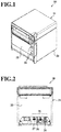
- FIG. 1 is a front perspective view of a printer 30 according to at least one embodiment of the present invention.
- the printer 30 includes a housing 31 formed into a cube, and a printer cover 32 rotatably connected to the housing 31.
- the housing 31 is made of a composite resin material or a metal material, for example, and includes a plurality of outside surfaces including a bottom surface 33 opposed to an installation surface (not shown) on which the printer 30 is installed.
- the printer 30 is a thermal printer configured to perform printing on heat-sensitive paper serving as roll-type recording paper with heat.
- the heat-sensitive paper is housed inside the housing 31.
- buttons 34 are arranged in a state of being exposed to be depressible on an outside surface of the printer cover 32.
- Examples of the operation buttons 34 include a power button and a feed button.
- One of the operation buttons 34 serving as the power button is configured to switch between power on and off of the printer 30 based on a depression operation.
- the other of the operation buttons 34 serving as the feed button is configured to perform feed processing of conveying the heat-sensitive paper by a predetermined pitch based on a depression operation. Further, when the depression operation is performed on both of the operation buttons 34 at the same time, the printer 30 performs test print processing of printing a predetermined test pattern on the heat-sensitive paper.
- FIG. 2 is a bottom view of the printer 30 according to the at least one embodiment.
- various connection connectors 35 used to connect peripheral devices to the printer 30 are provided on the bottom surface 33 of the housing 31.
- the connection connectors 35 at least include a power supply connector 36 used to input DC power supplied from a power supply adaptor 20 (see FIG. 3 ), which is to be described later and serves as an outside, to the printer 30, a Universal Serial Bus (USB) connector 37 used to output a part of the DC power supplied from the power supply adaptor 20 and data to a communication terminal 50 to be described later, and an interface (I/F) connector 38 used to connect a display device (not shown), for example.
- USB Universal Serial Bus
- This USB connector 37 complies with the USB Power Delivery specification, and a USB cable 40 (see FIG. 3 ) of the USB Type-C specification can be connected thereto.
- the power supply connector 36 is an example of "first connector”
- the USB connector 37 is an example of "second connector.”
- This power control system 10 has a function of the printer 30 supplying a part of the DC power supplied from the power supply adaptor 20 to the communication terminal 50 connected to the printer 30 through the USB cable 40.
- the power supply adaptor 20 is configured to rectify an input of AC 100 V which is input via a power supply (not shown) to supply the DC power to the printer 30.
- the communication terminal 50 is a terminal device which is connected to the printer 30 through the USB cable 40 and can communicate to/from the printer 30.
- This communication terminal 50 includes a connection connector (not shown) to which the USB cable 40 of the USB Type-C specification can be connected.
- a Mobile Point of Sales (mPOS) terminal formed of a smartphone or a tablet terminal, for example, is used as an example of the communication terminal 50.
- the printer 30 includes a control device 60 configured to control operation of the printer 30, a printing unit 70, a Power Delivery (PD) controller 72, a DC/DC converter 74, the operation buttons 34, the power supply connector 36, the USB connector 37, and the I/F connector 38.
- the control device 60 and each of the above-mentioned components are connected to each other through an input/output interface (not shown).
- a central processing unit (CPU) 62 a read only memory (ROM) 64, a random access memory (RAM) 66, and a communication I/F unit 68 are connected to be communicable to/from one another.
- CPU central processing unit
- ROM read only memory
- RAM random access memory
- communication I/F unit 68 a communication I/F unit 68
- the CPU 62 is a central processing unit, and is configured to execute various programs and control the respective units.
- the CPU 62 is configured to read the programs from the ROM 64, and execute the programs with the RAM 66 serving as a work area.
- the CPU 62 is configured to perform control on the above-mentioned components and various kinds of arithmetic processing in accordance with the programs stored in the ROM 64.
- the ROM 64 is configured to store the various programs and various data.
- the various programs at least include a power control program for causing a computer to execute power control processing to be described later.
- the RAM 66 is configured to temporally store the programs and data as the work area.
- the communication I/F unit 68 is configured to perform wired communication or wireless communication to/from the communication terminal 50 and the peripheral devices connected via the I/F connector 38, for example.
- the printing unit 70 includes a head mechanism 76 configured to perform printing on the heat-sensitive paper, and a motor mechanism 78 configured to drive and rotate a roller (not shown) to convey the heat-sensitive paper by the predetermined pitch.
- the PD controller 72 is a controller integrated circuit (IC) that complies with the USB Type-C specification and the USB Power Delivery specification. This PD controller 72 is configured to receive data from the communication terminal 50 connected to the printer 30 through the USB cable 40, and transmit data to the communication terminal 50.
- IC controller integrated circuit
- the DC/DC converter 74 is configured to change the DC power supplied from the power supply adaptor 20 to the printer 30 into a predetermined voltage.
- the DC/DC converter 74 is configured to step down a 24-V voltage from the power supply adaptor 20 to a range of from 5 V to 20 V.
- the CPU 62 is configured to execute the programs stored in the ROM 64 to function as a data processing unit 80, a data analysis unit 82, a printing control unit 84, and an adjustment unit 86.
- the data processing unit 80 is configured to process input data. For example, when print data containing a content to be printed on the heat-sensitive paper is input from the communication terminal 50 or the I/F connector 38, the data processing unit 80 instructs the printing control unit 84 to perform print processing corresponding to the print data. Further, when the depression operation is performed on the feed button, for example, as one of the operation buttons 34, so that feed data for conveying the heat-sensitive paper by the predetermined pitch is input, the data processing unit 80 instructs the printing control unit 84 to perform feed processing corresponding to the feed data.
- the data analysis unit 82 is configured to analyze whether processing performed by the data processing unit 80 is processing accompanying printing on the heat-sensitive paper, specifically, the print processing or the test print processing, or other processing.
- the printing control unit 84 is configured to control operation of the printing unit 70. Specifically, when the print processing or the test print processing is to be performed, the printing control unit 84 controls a printing operation of performing printing on the heat-sensitive paper by the printing unit 70. When controlling the printing operation, the printing control unit 84 drives the head mechanism 76 and the motor mechanism 78 of the printing unit 70. In contrast, when performing processing other than the print processing or the test print processing, for example, the feed processing, the printing control unit 84 drives only the motor mechanism 78 of the printing unit 70.
- the adjustment unit 86 is configured to adjust a maximum amount of the DC power to be output from the USB connector 37.
- This adjustment unit 86 is configured to adjust the maximum amount of the DC power to be output from the USB connector 37, of the DC power supplied from the power supply adaptor 20, to a first amount of power when the printing unit 70 is not under the printing operation, and adjust the maximum amount of the DC power to be output from the USB connector 37 to a second amount of power when the printing unit 70 is under the printing operation, the second amount of power being smaller than the first amount of power.
- the first amount of power is an excess amount of power obtained by excluding, from an amount of power supplied from the power supply adaptor 20 to the printer 30, an amount of power used by the printer 30 when the printing unit 70 is not under the printing operation.
- the first amount of power is set, as an example, to " 100 W" which is a maximum amount of power that can be supplied from the printer 30 to the communication terminal 50 based on the USB Power Delivery specification.
- the second amount of power is an excess amount of power obtained by excluding, from the amount of power supplied from the power supply adaptor 20 to the printer 30, an amount of power used by the printer 30 when the printing unit 70 is under the printing operation.
- “the amount of power used by the printer 30 when the printing unit 70 is under the printing operation” is not variable for each printing operation, but is a predetermined constant value.
- the second amount of power is not variable for each printing operation, and is set to "10 W" across the board as an example.
- FIG. 5 is a flow chart for illustrating a flow of the power control processing.
- the printer 30 and the communication terminal 50 are connected to each other through the USB cable 40, data for requiring an amount of power to be supplied is transmitted from the communication terminal 50 to the printer 30. Then, when the amount of power desired by the communication terminal 50 to be supplied is within the first amount of power, the printer 30 supplies the desired amount of power. The amount of power desired by the communication terminal 50 is supplied from the printer 30 to the communication terminal 50.
- Step S10 illustrated in FIG. 5 the CPU 62 determines whether the printing unit 70 is under the printing operation. Specifically, the CPU 62 determines whether the print processing is being performed based on input of the print data from the communication terminal 50, and whether the test print processing is being performed based on the depression operation performed on both of the operation buttons 34 at the same time. Then, when the CPU 62 determines that the printing unit 70 is under the printing operation, the processing proceeds to Step S11, and when the CPU 62 does not determine that the printing unit 70 is under the printing operation, the processing proceeds to Step S18.
- Step S11 changing data for requiring consent to change the maximum amount of the DC power to be supplied is transmitted to the communication terminal 50.
- the PD controller 72 under control of the CPU 62, transmits, to the communication terminal 50, the changing data for requiring consent to change the maximum amount of the DC power to be output from the USB connector 37 from the first amount of power to the second amount of power. Then, the processing proceeds to Step S12.
- Step S12 it is determined whether the communication terminal 50 has given consent. Then, when the PD controller 72 receives response data of "with consent” from the communication terminal 50, the CPU 62 determines that the communication terminal 50 has given consent, and the processing proceeds to Step S13. In contrast, when the PD controller 72 receives response data of "without consent” from the communication terminal 50, the CPU 62 does not determine that the communication terminal 50 has given consent, and the processing repeats Step S12.
- Step S13 the CPU 62 adjusts the maximum amount of the DC power to be output from the USB connector 37 to the second amount of power.
- the PD controller 72 adjusts a current value of the DC power output from the DC/DC converter 74 so that the maximum amount of the DC power to be output from the USB connector 37 becomes the second amount of power. Then, the processing proceeds to Step S14.
- Step S14 the CPU 62 determines whether the printing operation of the printing unit 70 has been completed. Specifically, the CPU 62 determines whether a print job corresponding to the print processing or the test print processing that is being performed has been completed. When the CPU 62 determines that the printing operation of the printing unit 70 has been completed, the processing proceeds to Step S15. In contrast, when the CPU 62 does not determine that the printing operation of the printing unit 70 has been completed, the processing proceeds to Step S13.
- Step S15 the CPU 62 determines whether a certain time period has elapsed since the completion of the printing operation of the printing unit 70. Specifically, the CPU 62 determines whether the certain time period has elapsed since the completion of the most recently performed print job. When the CPU 62 determines that the certain time period has elapsed since the completion of the printing operation of the printing unit 70, the processing proceeds to Step S16. In contrast, when the CPU 62 does not determine that the certain time period has elapsed since the completion of the printing operation of the printing unit 70, the processing proceeds to Step S13.
- Step S16 changing data for requiring consent to change the maximum amount of the DC power to be supplied is transmitted to the communication terminal 50.
- the PD controller 72 under control of the CPU 62, transmits, to the communication terminal 50, the changing data for requiring consent to change the maximum amount of the DC power to be output from the USB connector 37 from the second amount of power to the first amount of power. Then, the processing proceeds to Step S17.
- Step S17 it is determined whether the communication terminal 50 has given consent.
- the CPU 62 determines that the communication terminal 50 has given consent, and the processing proceeds to Step S18.
- the CPU 62 does not determine that the communication terminal 50 has given consent, and the processing repeats Step S17.
- Step S 18 the CPU 62 adjusts the maximum amount of the DC power to be output from the USB connector 37 to the first amount of power.
- the PD controller 72 adjusts the current value of the DC power to be output from the DC/DC converter 74 so that the maximum amount of the DC power to be output from the USB connector 37 becomes the first amount of power. Then, the processing ends.
- the printer 30 includes the power supply connector 36 used to input the DC power supplied from the power supply adaptor 20, and the USB connector 37 used to output, to the communication terminal 50, at least a part of the DC power supplied from the power supply adaptor 20.
- the printer 30 further includes the printing control unit 84 configured to control operation of the printing unit 70, and the adjustment unit 86 configured to adjust the maximum amount of the DC power to be output from the USB connector 37, of the DC power supplied from the power supply adaptor 20, to the first amount of power when the printing unit 70 is not under the printing operation, and adjust the maximum amount of the DC power to be output from the USB connector 37 to the second amount of power when the printing unit 70 is under the printing operation, the second amount of power being smaller than the first amount of power. Therefore, according to the at least one embodiment, an amount of power supply to the communication terminal 50 can be adjusted depending on an operation status of the printer 30.
- the USB connector 37 in the at least one embodiment complies with the USB Power Delivery specification.
- the maximum amount of the DC power to be output from the USB connector 37 is " 100 W" as an example. Therefore, according to the at least one embodiment, as compared to a configuration including a connector that can output only a 2.5-W (5 V ⁇ 0.5 A) DC power in accordance with a related-art USB specification (for example, USB 2.0) that does not comply with the USB Power Delivery specification, larger DC power can be supplied to the communication terminal 50 connected to the printer 30.
- the printer 30 is a thermal printer configured to perform printing on the heat-sensitive paper with heat. Further, the thermal printer uses a larger amount of power for the printing operation than an inkjet printer configured to perform printing by directly applying ink to the recording paper. Therefore, when a set value of the amount of power supply to the communication terminal 50 exceeds the amount of power used by the printer 30 when the printing unit 70 is under the printing operation, the amount of power of the set value cannot be supplied during the printing operation, and there is a fear that power supply to the communication terminal 50 may be stopped.
- the maximum amount of the DC power to be output from the USB connector 37 is set to the second amount of power when the printing unit 70 is under the printing operation, and the second amount of power is set to the excess amount of power obtained by excluding, from the amount of power that can be supplied from the power supply adaptor 20, the amount of power used for the printing operation. Therefore, according to the at least one embodiment, the power supply to the communication terminal 50 can be prevented from being stopped during the printing operation of the printing unit 70.
- the adjustment unit 86 in the at least one embodiment maintains the maximum amount of the DC power to be output from the USB connector 37 at the second amount of power when the certain time period has not elapsed since the completion of the printing operation of the printing unit 70. In other words, the adjustment unit 86 maintains the second amount of power because, when a new print job is input before the certain time period elapses from the completion of the printing operation of the printing unit 70, the printing operation of the printing unit 70 is performed again.
- the adjustment unit 86 switches the maximum amount of the DC power to be output from the USB connector 37 from the second amount of power to the first amount of power when the certain time period has elapsed since the completion of the printing operation of the printing unit 70.
- the power supply connector 36 is a connector used to input the DC power supplied from the power supply adaptor 20.
- the present invention is not limited thereto, and the power supply connector 36 may be a connector used to input DC power supplied from an electronic device that complies with the USB Power Delivery specification.
- the power supply connector 36 may comply with the USB Power Delivery specification so that a USB cable of the USB Type-C specification can be connected thereto.
- the adjustment unit 86 can adjust the maximum amount of the DC power to be output from the USB connector 37 to the two types: the first amount of power and the second amount of power.
- the present invention is not limited thereto, and the adjustment unit 86 can adjust the maximum amount to three or more types.
- the adjustment unit 86 may adjust the maximum amount of the DC power to be output from the USB connector 37 to a third amount of power when the feed processing is being performed, the third amount of power being smaller than the first amount of power and larger than the second amount of power.
- the second amount of power is not variable for each printing operation, and is set to the amount of power across the board.
- the present invention is not limited thereto, and the second amount of power may be variable depending on the printing operation. For example, when a printing operation using an amount of power exceeding a predetermined value is being performed, the second amount of power is set to be lower than a reference value. In contrast, when a printing operation using an amount of power that is equal to or less than the predetermined value is being performed, the second amount of power may be set to be higher than the reference value.
Landscapes
- Engineering & Computer Science (AREA)
- General Engineering & Computer Science (AREA)
- Physics & Mathematics (AREA)
- General Physics & Mathematics (AREA)
- Theoretical Computer Science (AREA)
- Accessory Devices And Overall Control Thereof (AREA)
- Power Sources (AREA)
- Facsimiles In General (AREA)
- Electronic Switches (AREA)
Abstract
Description
- The present invention relates to a printer and a power control program.
- Hitherto, there has been known a technology of supplying, to a USB device connected to a USB port of a printer, electric power supplied from an AC power supply adapter to the printer.
- However, with the printer of the related art, an amount of power supply to the USB device may become short depending on an operation status of the printer.
- In view of the above, in this technical field, there have been demands for printer and a power control program with which an amount of power supply to a connected terminal can be adjusted depending on an operation status.
- According to a first aspect of the present invention, there is provided a printer, including: a first connector to be used to input electric power supplied from an outside; a second connector to which a communication terminal is to be connected, and which is to be used to output at least a part of the electric power to the connected communication terminal; a printing control unit configured to control operation of a printing unit configured to perform printing on recording paper; and an adjustment unit configured to adjust a maximum amount of the electric power to be output from the second connector, of the electric power supplied from the outside, to a first amount of power when the printing unit is not under a printing operation, and adjust the maximum amount of the electric power to be output from the second connector to a second amount of power when the printing unit is under the printing operation, the second amount of power being smaller than the first amount of power.
- Preferably, wherein the second connector complies with a USB Power Delivery specification.
- Preferably, the printer is a thermal printer, and wherein the second amount of power is an excess amount of power obtained by excluding, from an amount of power suppliable from the outside, an amount of power used for the printing operation of the printing unit.
- Preferably, the adjustment unit is configured to maintain the maximum amount of the electric power to be output from the second connector at the second amount of power when a certain time period has not elapsed since completion of the printing operation of the printing unit, and switch the maximum amount of the electric power to be output from the second connector from the second amount of power to the first amount of power when the certain time period has elapsed from the completion of the printing operation of the printing unit.
- According to another aspect of the present invention, there is provided a power control program, including: a printing control step of controlling operation of a printing unit configured to perform printing on recording paper; and an adjustment step of adjusting a maximum amount of electric power to be output from a second connector, of the electric power supplied through a first connector used to input the electric power supplied from an outside, to a first amount of power when the printing unit is not under a printing operation, and adjusting the maximum amount of the electric power to be output from the second connector to a second amount of power when the printing unit is under the printing operation, the second connector having a communication terminal connected thereto, and being used to output at least a part of the electric power to the connected communication terminal, the second amount of power being smaller than the first amount of power.
- Embodiments of the present invention will now be described by way of example only with reference to the accompanying drawings.
-
FIG. 1 is a front perspective view of a printer according to at least one embodiment of the present invention. -
FIG. 2 is a bottom view of the printer according to the at least one embodiment. -
FIG. 3 is a system configuration diagram of a power control system in the at least one embodiment. -
FIG. 4 is a block diagram for illustrating a functional configuration of a CPU in the at least one embodiment. -
FIG. 5 is a flow chart for illustrating a flow of power control processing in the at least one embodiment. -
FIG. 1 is a front perspective view of aprinter 30 according to at least one embodiment of the present invention. As illustrated inFIG. 1 , theprinter 30 includes ahousing 31 formed into a cube, and aprinter cover 32 rotatably connected to thehousing 31. Thehousing 31 is made of a composite resin material or a metal material, for example, and includes a plurality of outside surfaces including abottom surface 33 opposed to an installation surface (not shown) on which theprinter 30 is installed. - The
printer 30 is a thermal printer configured to perform printing on heat-sensitive paper serving as roll-type recording paper with heat. The heat-sensitive paper is housed inside thehousing 31. - On the
printer cover 32, twooperation buttons 34 are arranged in a state of being exposed to be depressible on an outside surface of theprinter cover 32. Examples of theoperation buttons 34 include a power button and a feed button. - One of the
operation buttons 34 serving as the power button is configured to switch between power on and off of theprinter 30 based on a depression operation. - The other of the
operation buttons 34 serving as the feed button is configured to perform feed processing of conveying the heat-sensitive paper by a predetermined pitch based on a depression operation. Further, when the depression operation is performed on both of theoperation buttons 34 at the same time, theprinter 30 performs test print processing of printing a predetermined test pattern on the heat-sensitive paper. -
FIG. 2 is a bottom view of theprinter 30 according to the at least one embodiment. As illustrated inFIG. 2 ,various connection connectors 35 used to connect peripheral devices to theprinter 30 are provided on thebottom surface 33 of thehousing 31. Theconnection connectors 35 at least include apower supply connector 36 used to input DC power supplied from a power supply adaptor 20 (seeFIG. 3 ), which is to be described later and serves as an outside, to theprinter 30, a Universal Serial Bus (USB)connector 37 used to output a part of the DC power supplied from thepower supply adaptor 20 and data to acommunication terminal 50 to be described later, and an interface (I/F)connector 38 used to connect a display device (not shown), for example. ThisUSB connector 37 complies with the USB Power Delivery specification, and a USB cable 40 (seeFIG. 3 ) of the USB Type-C specification can be connected thereto. Thepower supply connector 36 is an example of "first connector," and theUSB connector 37 is an example of "second connector." - Next, referring to
FIG. 3 , apower control system 10 in the at least one embodiment is described. Thispower control system 10 has a function of theprinter 30 supplying a part of the DC power supplied from thepower supply adaptor 20 to thecommunication terminal 50 connected to theprinter 30 through theUSB cable 40. - The
power supply adaptor 20 is configured to rectify an input of AC 100 V which is input via a power supply (not shown) to supply the DC power to theprinter 30. - The
communication terminal 50 is a terminal device which is connected to theprinter 30 through theUSB cable 40 and can communicate to/from theprinter 30. Thiscommunication terminal 50 includes a connection connector (not shown) to which theUSB cable 40 of the USB Type-C specification can be connected. In the at least one embodiment, a Mobile Point of Sales (mPOS) terminal formed of a smartphone or a tablet terminal, for example, is used as an example of thecommunication terminal 50. - Next, a hardware configuration of the
printer 30 is described. As illustrated inFIG. 3 , theprinter 30 includes acontrol device 60 configured to control operation of theprinter 30, aprinting unit 70, a Power Delivery (PD)controller 72, a DC/DC converter 74, theoperation buttons 34, thepower supply connector 36, theUSB connector 37, and the I/F connector 38. Thecontrol device 60 and each of the above-mentioned components are connected to each other through an input/output interface (not shown). - In the
control device 60, a central processing unit (CPU) 62, a read only memory (ROM) 64, a random access memory (RAM) 66, and a communication I/F unit 68 are connected to be communicable to/from one another. - The
CPU 62 is a central processing unit, and is configured to execute various programs and control the respective units. In other words, theCPU 62 is configured to read the programs from theROM 64, and execute the programs with theRAM 66 serving as a work area. TheCPU 62 is configured to perform control on the above-mentioned components and various kinds of arithmetic processing in accordance with the programs stored in theROM 64. - The
ROM 64 is configured to store the various programs and various data. The various programs at least include a power control program for causing a computer to execute power control processing to be described later. - The
RAM 66 is configured to temporally store the programs and data as the work area. The communication I/F unit 68 is configured to perform wired communication or wireless communication to/from thecommunication terminal 50 and the peripheral devices connected via the I/F connector 38, for example. - The
printing unit 70 includes ahead mechanism 76 configured to perform printing on the heat-sensitive paper, and amotor mechanism 78 configured to drive and rotate a roller (not shown) to convey the heat-sensitive paper by the predetermined pitch. - The
PD controller 72 is a controller integrated circuit (IC) that complies with the USB Type-C specification and the USB Power Delivery specification. ThisPD controller 72 is configured to receive data from thecommunication terminal 50 connected to theprinter 30 through theUSB cable 40, and transmit data to thecommunication terminal 50. - The DC/
DC converter 74 is configured to change the DC power supplied from thepower supply adaptor 20 to theprinter 30 into a predetermined voltage. For example, the DC/DC converter 74 is configured to step down a 24-V voltage from thepower supply adaptor 20 to a range of from 5 V to 20 V. - Next, referring to
FIG. 4 , functions of theCPU 62 are described. As illustrated inFIG. 4 , theCPU 62 is configured to execute the programs stored in theROM 64 to function as adata processing unit 80, adata analysis unit 82, aprinting control unit 84, and anadjustment unit 86. - The
data processing unit 80 is configured to process input data. For example, when print data containing a content to be printed on the heat-sensitive paper is input from thecommunication terminal 50 or the I/F connector 38, thedata processing unit 80 instructs theprinting control unit 84 to perform print processing corresponding to the print data. Further, when the depression operation is performed on the feed button, for example, as one of theoperation buttons 34, so that feed data for conveying the heat-sensitive paper by the predetermined pitch is input, thedata processing unit 80 instructs theprinting control unit 84 to perform feed processing corresponding to the feed data. - The
data analysis unit 82 is configured to analyze whether processing performed by thedata processing unit 80 is processing accompanying printing on the heat-sensitive paper, specifically, the print processing or the test print processing, or other processing. - The
printing control unit 84 is configured to control operation of theprinting unit 70. Specifically, when the print processing or the test print processing is to be performed, theprinting control unit 84 controls a printing operation of performing printing on the heat-sensitive paper by theprinting unit 70. When controlling the printing operation, theprinting control unit 84 drives thehead mechanism 76 and themotor mechanism 78 of theprinting unit 70. In contrast, when performing processing other than the print processing or the test print processing, for example, the feed processing, theprinting control unit 84 drives only themotor mechanism 78 of theprinting unit 70. - The
adjustment unit 86 is configured to adjust a maximum amount of the DC power to be output from theUSB connector 37. Thisadjustment unit 86 is configured to adjust the maximum amount of the DC power to be output from theUSB connector 37, of the DC power supplied from thepower supply adaptor 20, to a first amount of power when theprinting unit 70 is not under the printing operation, and adjust the maximum amount of the DC power to be output from theUSB connector 37 to a second amount of power when theprinting unit 70 is under the printing operation, the second amount of power being smaller than the first amount of power. - The first amount of power is an excess amount of power obtained by excluding, from an amount of power supplied from the
power supply adaptor 20 to theprinter 30, an amount of power used by theprinter 30 when theprinting unit 70 is not under the printing operation. In the at least one embodiment, the first amount of power is set, as an example, to " 100 W" which is a maximum amount of power that can be supplied from theprinter 30 to thecommunication terminal 50 based on the USB Power Delivery specification. - The second amount of power is an excess amount of power obtained by excluding, from the amount of power supplied from the
power supply adaptor 20 to theprinter 30, an amount of power used by theprinter 30 when theprinting unit 70 is under the printing operation. In the at least one embodiment, "the amount of power used by theprinter 30 when theprinting unit 70 is under the printing operation" is not variable for each printing operation, but is a predetermined constant value. As a result, in the at least one embodiment, the second amount of power is not variable for each printing operation, and is set to "10 W" across the board as an example. -
FIG. 5 is a flow chart for illustrating a flow of the power control processing. In the at least one embodiment, when theprinter 30 and thecommunication terminal 50 are connected to each other through theUSB cable 40, data for requiring an amount of power to be supplied is transmitted from thecommunication terminal 50 to theprinter 30. Then, when the amount of power desired by thecommunication terminal 50 to be supplied is within the first amount of power, theprinter 30 supplies the desired amount of power. The amount of power desired by thecommunication terminal 50 is supplied from theprinter 30 to thecommunication terminal 50. - In Step S10 illustrated in
FIG. 5 , theCPU 62 determines whether theprinting unit 70 is under the printing operation. Specifically, theCPU 62 determines whether the print processing is being performed based on input of the print data from thecommunication terminal 50, and whether the test print processing is being performed based on the depression operation performed on both of theoperation buttons 34 at the same time. Then, when theCPU 62 determines that theprinting unit 70 is under the printing operation, the processing proceeds to Step S11, and when theCPU 62 does not determine that theprinting unit 70 is under the printing operation, the processing proceeds to Step S18. - In Step S11, changing data for requiring consent to change the maximum amount of the DC power to be supplied is transmitted to the
communication terminal 50. Specifically, in Step S11, under control of theCPU 62, thePD controller 72 transmits, to thecommunication terminal 50, the changing data for requiring consent to change the maximum amount of the DC power to be output from theUSB connector 37 from the first amount of power to the second amount of power. Then, the processing proceeds to Step S12. - In Step S12, it is determined whether the
communication terminal 50 has given consent. Then, when thePD controller 72 receives response data of "with consent" from thecommunication terminal 50, theCPU 62 determines that thecommunication terminal 50 has given consent, and the processing proceeds to Step S13. In contrast, when thePD controller 72 receives response data of "without consent" from thecommunication terminal 50, theCPU 62 does not determine that thecommunication terminal 50 has given consent, and the processing repeats Step S12. - In Step S13, the
CPU 62 adjusts the maximum amount of the DC power to be output from theUSB connector 37 to the second amount of power. For example, in Step S13, under control of theCPU 62, thePD controller 72 adjusts a current value of the DC power output from the DC/DC converter 74 so that the maximum amount of the DC power to be output from theUSB connector 37 becomes the second amount of power. Then, the processing proceeds to Step S14. - In Step S14, the
CPU 62 determines whether the printing operation of theprinting unit 70 has been completed. Specifically, theCPU 62 determines whether a print job corresponding to the print processing or the test print processing that is being performed has been completed. When theCPU 62 determines that the printing operation of theprinting unit 70 has been completed, the processing proceeds to Step S15. In contrast, when theCPU 62 does not determine that the printing operation of theprinting unit 70 has been completed, the processing proceeds to Step S13. - In Step S15, the
CPU 62 determines whether a certain time period has elapsed since the completion of the printing operation of theprinting unit 70. Specifically, theCPU 62 determines whether the certain time period has elapsed since the completion of the most recently performed print job. When theCPU 62 determines that the certain time period has elapsed since the completion of the printing operation of theprinting unit 70, the processing proceeds to Step S16. In contrast, when theCPU 62 does not determine that the certain time period has elapsed since the completion of the printing operation of theprinting unit 70, the processing proceeds to Step S13. - In Step S16, changing data for requiring consent to change the maximum amount of the DC power to be supplied is transmitted to the
communication terminal 50. Specifically, in Step S16, under control of theCPU 62, thePD controller 72 transmits, to thecommunication terminal 50, the changing data for requiring consent to change the maximum amount of the DC power to be output from theUSB connector 37 from the second amount of power to the first amount of power. Then, the processing proceeds to Step S17. - In Step S17, it is determined whether the
communication terminal 50 has given consent. When thePD controller 72 receives the response data of "with consent" from thecommunication terminal 50, theCPU 62 determines that thecommunication terminal 50 has given consent, and the processing proceeds to Step S18. In contrast, when thePD controller 72 receives the response data of "without consent" from thecommunication terminal 50, theCPU 62 does not determine that thecommunication terminal 50 has given consent, and the processing repeats Step S17. - In Step S 18, the
CPU 62 adjusts the maximum amount of the DC power to be output from theUSB connector 37 to the first amount of power. For example, in Step S 18, under control of theCPU 62, thePD controller 72 adjusts the current value of the DC power to be output from the DC/DC converter 74 so that the maximum amount of the DC power to be output from theUSB connector 37 becomes the first amount of power. Then, the processing ends. - The
printer 30 according to the at least one embodiment includes thepower supply connector 36 used to input the DC power supplied from thepower supply adaptor 20, and theUSB connector 37 used to output, to thecommunication terminal 50, at least a part of the DC power supplied from thepower supply adaptor 20. Theprinter 30 further includes theprinting control unit 84 configured to control operation of theprinting unit 70, and theadjustment unit 86 configured to adjust the maximum amount of the DC power to be output from theUSB connector 37, of the DC power supplied from thepower supply adaptor 20, to the first amount of power when theprinting unit 70 is not under the printing operation, and adjust the maximum amount of the DC power to be output from theUSB connector 37 to the second amount of power when theprinting unit 70 is under the printing operation, the second amount of power being smaller than the first amount of power. Therefore, according to the at least one embodiment, an amount of power supply to thecommunication terminal 50 can be adjusted depending on an operation status of theprinter 30. - The
USB connector 37 in the at least one embodiment complies with the USB Power Delivery specification. As a result, the maximum amount of the DC power to be output from theUSB connector 37 is " 100 W" as an example. Therefore, according to the at least one embodiment, as compared to a configuration including a connector that can output only a 2.5-W (5 V∗0.5 A) DC power in accordance with a related-art USB specification (for example, USB 2.0) that does not comply with the USB Power Delivery specification, larger DC power can be supplied to thecommunication terminal 50 connected to theprinter 30. - The
printer 30 according to the at least one embodiment is a thermal printer configured to perform printing on the heat-sensitive paper with heat. Further, the thermal printer uses a larger amount of power for the printing operation than an inkjet printer configured to perform printing by directly applying ink to the recording paper. Therefore, when a set value of the amount of power supply to thecommunication terminal 50 exceeds the amount of power used by theprinter 30 when theprinting unit 70 is under the printing operation, the amount of power of the set value cannot be supplied during the printing operation, and there is a fear that power supply to thecommunication terminal 50 may be stopped. - In view of the above-mentioned problem, in the at least one embodiment, the maximum amount of the DC power to be output from the
USB connector 37 is set to the second amount of power when theprinting unit 70 is under the printing operation, and the second amount of power is set to the excess amount of power obtained by excluding, from the amount of power that can be supplied from thepower supply adaptor 20, the amount of power used for the printing operation. Therefore, according to the at least one embodiment, the power supply to thecommunication terminal 50 can be prevented from being stopped during the printing operation of theprinting unit 70. - The
adjustment unit 86 in the at least one embodiment maintains the maximum amount of the DC power to be output from theUSB connector 37 at the second amount of power when the certain time period has not elapsed since the completion of the printing operation of theprinting unit 70. In other words, theadjustment unit 86 maintains the second amount of power because, when a new print job is input before the certain time period elapses from the completion of the printing operation of theprinting unit 70, the printing operation of theprinting unit 70 is performed again. - In contrast, the
adjustment unit 86 switches the maximum amount of the DC power to be output from theUSB connector 37 from the second amount of power to the first amount of power when the certain time period has elapsed since the completion of the printing operation of theprinting unit 70. With the above-mentioned configuration, according to the at least one embodiment, an appropriate amount of power can be supplied to thecommunication terminal 50 depending on the operation status of theprinter 30. - In the above-mentioned at least one embodiment, the
power supply connector 36 is a connector used to input the DC power supplied from thepower supply adaptor 20. However, the present invention is not limited thereto, and thepower supply connector 36 may be a connector used to input DC power supplied from an electronic device that complies with the USB Power Delivery specification. In other words, thepower supply connector 36 may comply with the USB Power Delivery specification so that a USB cable of the USB Type-C specification can be connected thereto. - In the above-mentioned at least one embodiment, the
adjustment unit 86 can adjust the maximum amount of the DC power to be output from theUSB connector 37 to the two types: the first amount of power and the second amount of power. However, the present invention is not limited thereto, and theadjustment unit 86 can adjust the maximum amount to three or more types. For example, theadjustment unit 86 may adjust the maximum amount of the DC power to be output from theUSB connector 37 to a third amount of power when the feed processing is being performed, the third amount of power being smaller than the first amount of power and larger than the second amount of power. - In the above-mentioned at least one embodiment, the second amount of power is not variable for each printing operation, and is set to the amount of power across the board. However, the present invention is not limited thereto, and the second amount of power may be variable depending on the printing operation. For example, when a printing operation using an amount of power exceeding a predetermined value is being performed, the second amount of power is set to be lower than a reference value. In contrast, when a printing operation using an amount of power that is equal to or less than the predetermined value is being performed, the second amount of power may be set to be higher than the reference value.
- The foregoing description explains the present invention by way of example and the skilled addressee will appreciate that various modifications can be made without departing from the scope of the invention as defined in the appended claims.
Claims (5)
- A printer (30), comprising:a first connector (36) to be used to input electric power supplied from an outside;a second connector (37) to which a communication terminal (50) is to be connected, and which is to be used to output at least a part of the electric power to the connected communication terminal (50);a printing control unit (84) configured to control operation of a printing unit (70) configured to perform printing on recording paper; andan adjustment unit (86) configured to adjust a maximum amount of the electric power to be output from the second connector (37), of the electric power supplied from the outside, to a first amount of power when the printing unit (70) is not under a printing operation, and adjust the maximum amount of the electric power to be output from the second connector (37) to a second amount of power when the printing unit (70) is under the printing operation, the second amount of power being smaller than the first amount of power.
- The printer (30) according to claim 1, wherein the second connector (37) complies with a USB Power Delivery specification.
- The printer (30) according to claim 1 or claim 2,
wherein the printer (30) is a thermal printer, and
wherein the second amount of power is an excess amount of power obtained by excluding, from an amount of power suppliable from the outside, an amount of power used for the printing operation of the printing unit (70). - The printer (30) according to any one of the preceding claims, wherein the adjustment unit (86) is configured to maintain the maximum amount of the electric power to be output from the second connector (37) at the second amount of power when a certain time period has not elapsed since completion of the printing operation of the printing unit (70), and switch the maximum amount of the electric power to be output from the second connector (37) from the second amount of power to the first amount of power when the certain time period has elapsed from the completion of the printing operation of the printing unit (70).
- A power control program for causing a computer to execute processing including:a printing control step of controlling operation of a printing unit (70) configured to perform printing on recording paper; andan adjustment step of adjusting a maximum amount of electric power to be output from a second connector (37), of the electric power supplied through a first connector (36) used to input the electric power supplied from an outside, to a first amount of power when the printing unit (70) is not under a printing operation, and adjusting the maximum amount of the electric power to be output from the second connector (37) to a second amount of power when the printing unit (70) is under the printing operation, the second connector (37) having a communication terminal (50) connected thereto, and being used to output at least a part of the electric power to the connected communication terminal (50), the second amount of power being smaller than the first amount of power.
Applications Claiming Priority (1)
| Application Number | Priority Date | Filing Date | Title |
|---|---|---|---|
| JP2020062301A JP2021163019A (en) | 2020-03-31 | 2020-03-31 | Printer and power control program |
Publications (2)
| Publication Number | Publication Date |
|---|---|
| EP3888926A1 true EP3888926A1 (en) | 2021-10-06 |
| EP3888926B1 EP3888926B1 (en) | 2023-11-08 |
Family
ID=75302249
Family Applications (1)
| Application Number | Title | Priority Date | Filing Date |
|---|---|---|---|
| EP21165795.2A Active EP3888926B1 (en) | 2020-03-31 | 2021-03-30 | Printer and power control program |
Country Status (3)
| Country | Link |
|---|---|
| US (1) | US11494601B2 (en) |
| EP (1) | EP3888926B1 (en) |
| JP (2) | JP2021163019A (en) |
Citations (4)
| Publication number | Priority date | Publication date | Assignee | Title |
|---|---|---|---|---|
| US6072585A (en) * | 1997-12-12 | 2000-06-06 | Lexmark International, Inc. | Method and apparatus for managing the power consumption of a printer |
| US20050050371A1 (en) * | 2003-08-27 | 2005-03-03 | Yasumasa Ono | Image sensing apparatus and power managing method |
| US20180284865A1 (en) * | 2017-03-28 | 2018-10-04 | Brother Kogyo Kabushiki Kaisha | Power Supply Apparatus |
| US10406823B2 (en) * | 2016-12-26 | 2019-09-10 | Casio Computer Co., Ltd. | Printing device, method of controlling printing device, and computer-readable storage medium |
Family Cites Families (4)
| Publication number | Priority date | Publication date | Assignee | Title |
|---|---|---|---|---|
| JP2009205538A (en) * | 2008-02-28 | 2009-09-10 | Canon Inc | Electronic apparatus, power state control method and computer program |
| JP6448200B2 (en) * | 2014-03-17 | 2019-01-09 | キヤノン株式会社 | Printing apparatus, control method therefor, and program |
| JP6375826B2 (en) | 2014-09-24 | 2018-08-22 | スター精密株式会社 | Supply power control device |
| JP7452157B2 (en) * | 2020-03-24 | 2024-03-19 | ブラザー工業株式会社 | printing device |
-
2020
- 2020-03-31 JP JP2020062301A patent/JP2021163019A/en active Pending
-
2021
- 2021-03-26 US US17/214,480 patent/US11494601B2/en active Active
- 2021-03-30 EP EP21165795.2A patent/EP3888926B1/en active Active
-
2024
- 2024-01-31 JP JP2024012582A patent/JP2024040232A/en active Pending
Patent Citations (4)
| Publication number | Priority date | Publication date | Assignee | Title |
|---|---|---|---|---|
| US6072585A (en) * | 1997-12-12 | 2000-06-06 | Lexmark International, Inc. | Method and apparatus for managing the power consumption of a printer |
| US20050050371A1 (en) * | 2003-08-27 | 2005-03-03 | Yasumasa Ono | Image sensing apparatus and power managing method |
| US10406823B2 (en) * | 2016-12-26 | 2019-09-10 | Casio Computer Co., Ltd. | Printing device, method of controlling printing device, and computer-readable storage medium |
| US20180284865A1 (en) * | 2017-03-28 | 2018-10-04 | Brother Kogyo Kabushiki Kaisha | Power Supply Apparatus |
Also Published As
| Publication number | Publication date |
|---|---|
| US20210303953A1 (en) | 2021-09-30 |
| US11494601B2 (en) | 2022-11-08 |
| JP2024040232A (en) | 2024-03-25 |
| JP2021163019A (en) | 2021-10-11 |
| EP3888926B1 (en) | 2023-11-08 |
Similar Documents
| Publication | Publication Date | Title |
|---|---|---|
| US5671149A (en) | Programmable board mounted voltage regulators | |
| US11223734B2 (en) | Information processing apparatus, method of controlling information processing apparatus, and non-transitory computer-readable recording medium | |
| US20100164299A1 (en) | Remote Controllable Power Outlet Apparatus with Grouping Capability and Remote Control Grouping Method Thereof | |
| EP3888926A1 (en) | Printer and power control program | |
| US11356575B2 (en) | Printing apparatus | |
| CN103780785A (en) | Electronic device and control method thereof | |
| TW201405295A (en) | Power supply circuit | |
| JP5122379B2 (en) | Portable printer | |
| US11418670B2 (en) | Printing apparatus connected to an external power supply having a plurality of voltage information | |
| JP7091706B2 (en) | Image processing equipment | |
| JP7484392B2 (en) | Printing device | |
| JP7392548B2 (en) | printing device | |
| JP2021164337A (en) | Charging device, printer, and charging method | |
| CN107933096B (en) | Printing apparatus, control method thereof, and storage medium | |
| JP2011103565A (en) | Mobile information terminal and method of controlling the same, and program | |
| JPH09120325A (en) | Network connecting device | |
| US11579821B2 (en) | Printing apparatus | |
| CN109459918B (en) | Image forming apparatus with a toner supply device | |
| JP6225866B2 (en) | Image forming apparatus | |
| JP2009143037A (en) | Control device having parallel communication interface, printer controller, printer, and compound apparatus | |
| CN111273785A (en) | External keyboard and data transmission method of keyboard | |
| JPS62149473A (en) | Power source device | |
| JP2001199126A (en) | Electronic device or printer | |
| CN114520582A (en) | Power supply circuit and electronic device | |
| CN117295664A (en) | Printing system, control method for printing system, printer, and program |
Legal Events
| Date | Code | Title | Description |
|---|---|---|---|
| PUAI | Public reference made under article 153(3) epc to a published international application that has entered the european phase |
Free format text: ORIGINAL CODE: 0009012 |
|
| STAA | Information on the status of an ep patent application or granted ep patent |
Free format text: STATUS: THE APPLICATION HAS BEEN PUBLISHED |
|
| AK | Designated contracting states |
Kind code of ref document: A1 Designated state(s): AL AT BE BG CH CY CZ DE DK EE ES FI FR GB GR HR HU IE IS IT LI LT LU LV MC MK MT NL NO PL PT RO RS SE SI SK SM TR |
|
| STAA | Information on the status of an ep patent application or granted ep patent |
Free format text: STATUS: REQUEST FOR EXAMINATION WAS MADE |
|
| 17P | Request for examination filed |
Effective date: 20220323 |
|
| RBV | Designated contracting states (corrected) |
Designated state(s): AL AT BE BG CH CY CZ DE DK EE ES FI FR GB GR HR HU IE IS IT LI LT LU LV MC MK MT NL NO PL PT RO RS SE SI SK SM TR |
|
| REG | Reference to a national code |
Ref country code: DE Ref legal event code: R079 Ref document number: 602021006541 Country of ref document: DE Free format text: PREVIOUS MAIN CLASS: B41J0029380000 Ipc: B41J0002355000 Ref country code: DE Ref legal event code: R079 Free format text: PREVIOUS MAIN CLASS: B41J0029380000 Ipc: B41J0002355000 |
|
| GRAP | Despatch of communication of intention to grant a patent |
Free format text: ORIGINAL CODE: EPIDOSNIGR1 |
|
| STAA | Information on the status of an ep patent application or granted ep patent |
Free format text: STATUS: GRANT OF PATENT IS INTENDED |
|
| RIC1 | Information provided on ipc code assigned before grant |
Ipc: B41J 2/32 20060101ALI20230509BHEP Ipc: B41J 29/393 20060101ALI20230509BHEP Ipc: B41J 29/38 20060101ALI20230509BHEP Ipc: B41J 2/355 20060101AFI20230509BHEP |
|
| INTG | Intention to grant announced |
Effective date: 20230601 |
|
| GRAS | Grant fee paid |
Free format text: ORIGINAL CODE: EPIDOSNIGR3 |
|
| GRAA | (expected) grant |
Free format text: ORIGINAL CODE: 0009210 |
|
| STAA | Information on the status of an ep patent application or granted ep patent |
Free format text: STATUS: THE PATENT HAS BEEN GRANTED |
|
| P01 | Opt-out of the competence of the unified patent court (upc) registered |
Effective date: 20230912 |
|
| AK | Designated contracting states |
Kind code of ref document: B1 Designated state(s): AL AT BE BG CH CY CZ DE DK EE ES FI FR GB GR HR HU IE IS IT LI LT LU LV MC MK MT NL NO PL PT RO RS SE SI SK SM TR |
|
| REG | Reference to a national code |
Ref country code: GB Ref legal event code: FG4D |
|
| REG | Reference to a national code |
Ref country code: CH Ref legal event code: EP |
|
| REG | Reference to a national code |
Ref country code: DE Ref legal event code: R096 Ref document number: 602021006541 Country of ref document: DE |
|
| REG | Reference to a national code |
Ref country code: IE Ref legal event code: FG4D |
|
| REG | Reference to a national code |
Ref country code: LT Ref legal event code: MG9D |
|
| REG | Reference to a national code |
Ref country code: NL Ref legal event code: MP Effective date: 20231108 |
|
| PG25 | Lapsed in a contracting state [announced via postgrant information from national office to epo] |
Ref country code: GR Free format text: LAPSE BECAUSE OF FAILURE TO SUBMIT A TRANSLATION OF THE DESCRIPTION OR TO PAY THE FEE WITHIN THE PRESCRIBED TIME-LIMIT Effective date: 20240209 |
|
| PG25 | Lapsed in a contracting state [announced via postgrant information from national office to epo] |
Ref country code: IS Free format text: LAPSE BECAUSE OF FAILURE TO SUBMIT A TRANSLATION OF THE DESCRIPTION OR TO PAY THE FEE WITHIN THE PRESCRIBED TIME-LIMIT Effective date: 20240308 |
|
| PG25 | Lapsed in a contracting state [announced via postgrant information from national office to epo] |
Ref country code: LT Free format text: LAPSE BECAUSE OF FAILURE TO SUBMIT A TRANSLATION OF THE DESCRIPTION OR TO PAY THE FEE WITHIN THE PRESCRIBED TIME-LIMIT Effective date: 20231108 |
|
| REG | Reference to a national code |
Ref country code: AT Ref legal event code: MK05 Ref document number: 1629300 Country of ref document: AT Kind code of ref document: T Effective date: 20231108 |
|
| PG25 | Lapsed in a contracting state [announced via postgrant information from national office to epo] |
Ref country code: NL Free format text: LAPSE BECAUSE OF FAILURE TO SUBMIT A TRANSLATION OF THE DESCRIPTION OR TO PAY THE FEE WITHIN THE PRESCRIBED TIME-LIMIT Effective date: 20231108 |
|
| PG25 | Lapsed in a contracting state [announced via postgrant information from national office to epo] |
Ref country code: AT Free format text: LAPSE BECAUSE OF FAILURE TO SUBMIT A TRANSLATION OF THE DESCRIPTION OR TO PAY THE FEE WITHIN THE PRESCRIBED TIME-LIMIT Effective date: 20231108 |
|
| PG25 | Lapsed in a contracting state [announced via postgrant information from national office to epo] |
Ref country code: ES Free format text: LAPSE BECAUSE OF FAILURE TO SUBMIT A TRANSLATION OF THE DESCRIPTION OR TO PAY THE FEE WITHIN THE PRESCRIBED TIME-LIMIT Effective date: 20231108 |
|
| PG25 | Lapsed in a contracting state [announced via postgrant information from national office to epo] |
Ref country code: NL Free format text: LAPSE BECAUSE OF FAILURE TO SUBMIT A TRANSLATION OF THE DESCRIPTION OR TO PAY THE FEE WITHIN THE PRESCRIBED TIME-LIMIT Effective date: 20231108 Ref country code: LT Free format text: LAPSE BECAUSE OF FAILURE TO SUBMIT A TRANSLATION OF THE DESCRIPTION OR TO PAY THE FEE WITHIN THE PRESCRIBED TIME-LIMIT Effective date: 20231108 Ref country code: IS Free format text: LAPSE BECAUSE OF FAILURE TO SUBMIT A TRANSLATION OF THE DESCRIPTION OR TO PAY THE FEE WITHIN THE PRESCRIBED TIME-LIMIT Effective date: 20240308 Ref country code: GR Free format text: LAPSE BECAUSE OF FAILURE TO SUBMIT A TRANSLATION OF THE DESCRIPTION OR TO PAY THE FEE WITHIN THE PRESCRIBED TIME-LIMIT Effective date: 20240209 Ref country code: ES Free format text: LAPSE BECAUSE OF FAILURE TO SUBMIT A TRANSLATION OF THE DESCRIPTION OR TO PAY THE FEE WITHIN THE PRESCRIBED TIME-LIMIT Effective date: 20231108 Ref country code: BG Free format text: LAPSE BECAUSE OF FAILURE TO SUBMIT A TRANSLATION OF THE DESCRIPTION OR TO PAY THE FEE WITHIN THE PRESCRIBED TIME-LIMIT Effective date: 20240208 Ref country code: AT Free format text: LAPSE BECAUSE OF FAILURE TO SUBMIT A TRANSLATION OF THE DESCRIPTION OR TO PAY THE FEE WITHIN THE PRESCRIBED TIME-LIMIT Effective date: 20231108 Ref country code: PT Free format text: LAPSE BECAUSE OF FAILURE TO SUBMIT A TRANSLATION OF THE DESCRIPTION OR TO PAY THE FEE WITHIN THE PRESCRIBED TIME-LIMIT Effective date: 20240308 |
|
| PGFP | Annual fee paid to national office [announced via postgrant information from national office to epo] |
Ref country code: DE Payment date: 20240206 Year of fee payment: 4 |