EP3888883A1 - Dispositif de prehension de preformes pour unite de chauffe - Google Patents
Dispositif de prehension de preformes pour unite de chauffe Download PDFInfo
- Publication number
- EP3888883A1 EP3888883A1 EP21165467.8A EP21165467A EP3888883A1 EP 3888883 A1 EP3888883 A1 EP 3888883A1 EP 21165467 A EP21165467 A EP 21165467A EP 3888883 A1 EP3888883 A1 EP 3888883A1
- Authority
- EP
- European Patent Office
- Prior art keywords
- mandrel
- end piece
- preforms
- contact
- cooling part
- Prior art date
- Legal status (The legal status is an assumption and is not a legal conclusion. Google has not performed a legal analysis and makes no representation as to the accuracy of the status listed.)
- Granted
Links
Images

Classifications
-
- B—PERFORMING OPERATIONS; TRANSPORTING
- B29—WORKING OF PLASTICS; WORKING OF SUBSTANCES IN A PLASTIC STATE IN GENERAL
- B29C—SHAPING OR JOINING OF PLASTICS; SHAPING OF MATERIAL IN A PLASTIC STATE, NOT OTHERWISE PROVIDED FOR; AFTER-TREATMENT OF THE SHAPED PRODUCTS, e.g. REPAIRING
- B29C49/00—Blow-moulding, i.e. blowing a preform or parison to a desired shape within a mould; Apparatus therefor
- B29C49/42—Component parts, details or accessories; Auxiliary operations
- B29C49/4205—Handling means, e.g. transfer, loading or discharging means
-
- B—PERFORMING OPERATIONS; TRANSPORTING
- B29—WORKING OF PLASTICS; WORKING OF SUBSTANCES IN A PLASTIC STATE IN GENERAL
- B29C—SHAPING OR JOINING OF PLASTICS; SHAPING OF MATERIAL IN A PLASTIC STATE, NOT OTHERWISE PROVIDED FOR; AFTER-TREATMENT OF THE SHAPED PRODUCTS, e.g. REPAIRING
- B29C49/00—Blow-moulding, i.e. blowing a preform or parison to a desired shape within a mould; Apparatus therefor
- B29C49/42—Component parts, details or accessories; Auxiliary operations
- B29C49/64—Heating or cooling preforms, parisons or blown articles
-
- B—PERFORMING OPERATIONS; TRANSPORTING
- B29—WORKING OF PLASTICS; WORKING OF SUBSTANCES IN A PLASTIC STATE IN GENERAL
- B29C—SHAPING OR JOINING OF PLASTICS; SHAPING OF MATERIAL IN A PLASTIC STATE, NOT OTHERWISE PROVIDED FOR; AFTER-TREATMENT OF THE SHAPED PRODUCTS, e.g. REPAIRING
- B29C49/00—Blow-moulding, i.e. blowing a preform or parison to a desired shape within a mould; Apparatus therefor
- B29C49/42—Component parts, details or accessories; Auxiliary operations
- B29C49/64—Heating or cooling preforms, parisons or blown articles
- B29C49/6409—Thermal conditioning of preforms
- B29C49/6418—Heating of preforms
-
- B—PERFORMING OPERATIONS; TRANSPORTING
- B29—WORKING OF PLASTICS; WORKING OF SUBSTANCES IN A PLASTIC STATE IN GENERAL
- B29C—SHAPING OR JOINING OF PLASTICS; SHAPING OF MATERIAL IN A PLASTIC STATE, NOT OTHERWISE PROVIDED FOR; AFTER-TREATMENT OF THE SHAPED PRODUCTS, e.g. REPAIRING
- B29C49/00—Blow-moulding, i.e. blowing a preform or parison to a desired shape within a mould; Apparatus therefor
- B29C49/42—Component parts, details or accessories; Auxiliary operations
- B29C49/64—Heating or cooling preforms, parisons or blown articles
- B29C49/6409—Thermal conditioning of preforms
- B29C49/6463—Thermal conditioning of preforms by contact heating or cooling, e.g. mandrels or cores specially adapted for heating or cooling preforms
-
- B—PERFORMING OPERATIONS; TRANSPORTING
- B29—WORKING OF PLASTICS; WORKING OF SUBSTANCES IN A PLASTIC STATE IN GENERAL
- B29C—SHAPING OR JOINING OF PLASTICS; SHAPING OF MATERIAL IN A PLASTIC STATE, NOT OTHERWISE PROVIDED FOR; AFTER-TREATMENT OF THE SHAPED PRODUCTS, e.g. REPAIRING
- B29C2949/00—Indexing scheme relating to blow-moulding
- B29C2949/07—Preforms or parisons characterised by their configuration
- B29C2949/0715—Preforms or parisons characterised by their configuration the preform having one end closed
-
- B—PERFORMING OPERATIONS; TRANSPORTING
- B29—WORKING OF PLASTICS; WORKING OF SUBSTANCES IN A PLASTIC STATE IN GENERAL
- B29C—SHAPING OR JOINING OF PLASTICS; SHAPING OF MATERIAL IN A PLASTIC STATE, NOT OTHERWISE PROVIDED FOR; AFTER-TREATMENT OF THE SHAPED PRODUCTS, e.g. REPAIRING
- B29C49/00—Blow-moulding, i.e. blowing a preform or parison to a desired shape within a mould; Apparatus therefor
- B29C49/02—Combined blow-moulding and manufacture of the preform or the parison
- B29C49/06—Injection blow-moulding
-
- B—PERFORMING OPERATIONS; TRANSPORTING
- B29—WORKING OF PLASTICS; WORKING OF SUBSTANCES IN A PLASTIC STATE IN GENERAL
- B29C—SHAPING OR JOINING OF PLASTICS; SHAPING OF MATERIAL IN A PLASTIC STATE, NOT OTHERWISE PROVIDED FOR; AFTER-TREATMENT OF THE SHAPED PRODUCTS, e.g. REPAIRING
- B29C49/00—Blow-moulding, i.e. blowing a preform or parison to a desired shape within a mould; Apparatus therefor
- B29C49/42—Component parts, details or accessories; Auxiliary operations
- B29C49/4205—Handling means, e.g. transfer, loading or discharging means
- B29C49/42073—Grippers
- B29C49/42085—Grippers holding inside the neck
-
- B—PERFORMING OPERATIONS; TRANSPORTING
- B29—WORKING OF PLASTICS; WORKING OF SUBSTANCES IN A PLASTIC STATE IN GENERAL
- B29C—SHAPING OR JOINING OF PLASTICS; SHAPING OF MATERIAL IN A PLASTIC STATE, NOT OTHERWISE PROVIDED FOR; AFTER-TREATMENT OF THE SHAPED PRODUCTS, e.g. REPAIRING
- B29C49/00—Blow-moulding, i.e. blowing a preform or parison to a desired shape within a mould; Apparatus therefor
- B29C49/42—Component parts, details or accessories; Auxiliary operations
- B29C49/64—Heating or cooling preforms, parisons or blown articles
- B29C49/6409—Thermal conditioning of preforms
-
- B—PERFORMING OPERATIONS; TRANSPORTING
- B29—WORKING OF PLASTICS; WORKING OF SUBSTANCES IN A PLASTIC STATE IN GENERAL
- B29C—SHAPING OR JOINING OF PLASTICS; SHAPING OF MATERIAL IN A PLASTIC STATE, NOT OTHERWISE PROVIDED FOR; AFTER-TREATMENT OF THE SHAPED PRODUCTS, e.g. REPAIRING
- B29C49/00—Blow-moulding, i.e. blowing a preform or parison to a desired shape within a mould; Apparatus therefor
- B29C49/42—Component parts, details or accessories; Auxiliary operations
- B29C49/64—Heating or cooling preforms, parisons or blown articles
- B29C49/6409—Thermal conditioning of preforms
- B29C49/6436—Thermal conditioning of preforms characterised by temperature differential
- B29C49/6445—Thermal conditioning of preforms characterised by temperature differential through the preform length
- B29C49/645—Thermal conditioning of preforms characterised by temperature differential through the preform length by cooling the neck
-
- B—PERFORMING OPERATIONS; TRANSPORTING
- B29—WORKING OF PLASTICS; WORKING OF SUBSTANCES IN A PLASTIC STATE IN GENERAL
- B29K—INDEXING SCHEME ASSOCIATED WITH SUBCLASSES B29B, B29C OR B29D, RELATING TO MOULDING MATERIALS OR TO MATERIALS FOR MOULDS, REINFORCEMENTS, FILLERS OR PREFORMED PARTS, e.g. INSERTS
- B29K2067/00—Use of polyesters or derivatives thereof, as moulding material
- B29K2067/003—PET, i.e. poylethylene terephthalate
-
- B—PERFORMING OPERATIONS; TRANSPORTING
- B29—WORKING OF PLASTICS; WORKING OF SUBSTANCES IN A PLASTIC STATE IN GENERAL
- B29L—INDEXING SCHEME ASSOCIATED WITH SUBCLASS B29C, RELATING TO PARTICULAR ARTICLES
- B29L2031/00—Other particular articles
- B29L2031/712—Containers; Packaging elements or accessories, Packages
-
- B—PERFORMING OPERATIONS; TRANSPORTING
- B29—WORKING OF PLASTICS; WORKING OF SUBSTANCES IN A PLASTIC STATE IN GENERAL
- B29L—INDEXING SCHEME ASSOCIATED WITH SUBCLASS B29C, RELATING TO PARTICULAR ARTICLES
- B29L2031/00—Other particular articles
- B29L2031/712—Containers; Packaging elements or accessories, Packages
- B29L2031/7158—Bottles
Definitions
- the field of the invention is that of the design and manufacture of plastic containers.
- the invention relates to a device for gripping preforms from a heating unit.
- a plastic container is conventionally formed by blow molding or stretch blow molding from a preform which comprises a substantially cylindrical body closed by a hemispherical bottom and, in contrast, an open neck having its final shape and separated from the body by a collar.
- the body and the bottom of the preform are subjected to heating in order to soften them by bringing them to a temperature (called the heating temperature) above the glass transition temperature of the material.
- the heating temperature is generally around 120 ° C.
- the heating of the preform is usually carried out in a heating unit equipped with light sources (generally halogen lamps or laser diodes).
- light sources generally halogen lamps or laser diodes.
- the preform is mounted on a rotating support called a “spinner”, which comprises a shaft provided at one end with a mandrel cooperating with the neck, and, at another end, with a pinion meshing with a rack.
- the spinner moves the preform past the light sources, while rotating it to expose the entire body to the light radiation from the light sources.
- the end pieces therefore leave, with the rings, a restricted annular space in which the neck of the preforms is intended to be housed.
- the mandrels, and in particular the end pieces heat up by their movement in areas of high temperatures of the heating unit, that is to say say near light sources.
- the mandrels include radiators making it possible to dissipate the calories by air circulation.
- the radiator is integral with the shaft and intended to come into contact with the end piece to allow heat dissipation by thermal conduction.
- the mandrels When gripping and unloading the preforms, the mandrels are moved away from the high temperature zones of the heating unit, which allows them to be cooled via the radiators.
- the mandrels continue to heat up but cannot cool down as much as necessary, which can lead to a risk of deformation of the necks of the preforms.
- the object of the invention is in particular to overcome the drawbacks of the prior art.
- the object of the invention is to propose a solution which allows the preforms to be gripped reliably while avoiding heating the neck of the preforms.
- the invention also aims to provide such a solution which is simple to use and maintain.
- the cooling part allows cooling of the nozzle by contact with ambient air and / or forced ventilation air.
- the light radiation heats the end piece, which it is then necessary to cool.
- the air in which the gripping devices operate is then cold enough to allow cooling of the nozzle by circulation along the nozzle. the cooling part of the mouthpiece.
- the mobility of the end piece on the mandrel makes it possible to ensure a flexible gripping of the preforms without exerting too great a force on the wheel holding the preforms prior to their being taken up by the gripping devices.
- this mobility makes it possible to be able to bring the end piece into contact with the radiator to also allow cooling by conduction between the end piece and the radiator.
- the presence of the cooling part allows the nozzle to be at a low operating temperature at the start of the heating cycle, despite a phase of temperature rise in the oven. During this temperature rise phase, the nozzles, although protected, can rise in temperature by convection with the temperature prevailing in the oven. In other words, in production, the mouthpiece with the cooling part makes it possible to maintain a lower operating temperature than if there was no cooling part on the mouthpiece.
- the cooling part comprises at least two reliefs axially spaced from each other.
- the or each relief is formed from an annular fin or as an annular portion which extends radially around the mandrel.
- a fin thus has three faces intended to come into contact with the ambient air, in order to increase the heat exchanges and therefore the cooling of the end piece.
- At least one of the reliefs of the cooling part has an overall dimension greater than an overall dimension of the penetrating part.
- the relief having an overall dimension greater than the overall dimension of the penetrating part makes it possible to form a stop for driving the penetrating part into the neck of the preforms.
- the penetrating part and the cooling part of the tip form a one-piece assembly.
- the end piece comprises at least two angular sectors for each of which the penetrating part and the cooling part of the end piece are formed integrally with one another.
- the penetrating part and the cooling part of the end piece are integral with each other.
- the means of contact by friction are integrated into the penetrating part and are in the form of at least one radial projection.
- the mandrel has a solid reflecting surface at its first end, intended to form means for reflecting light radiation from a light source of a heating unit.
- This solid reflecting surface therefore makes it possible to prevent the light radiation emitted by the light sources from heating the end piece of the gripping means, which prevents excessive cooling to be provided to the gripping means and in particular to the end piece.
- the mandrel has, at its first end, a shoulder intended to form a stop in translation of the end piece on the mandrel.
- the movement of the end piece on the mandrel is then limited between the shoulder and the radiator, so as to allow a gentle gripping of the preforms, while ensuring optimal cooling of the end piece by the latter coming into abutment on the radiator.
- the shoulder of the mandrel has an annular groove in which is received an annular bead carried by the penetrating part of the end piece.
- the invention also relates to a preform heating unit comprising at least one preform gripping device as described above.
- a device 100 for gripping a preform 2 comprises a mandrel 101, a support 102 mounted at a first end of the mandrel 101, means of contact 103 by friction with a preform 2 integral with the support 102 and a radiator 104 integral with the mandrel 101.
- the means of contact 103 by friction are formed of a ring mounted between the mandrel 101 on the one hand and the support 102 on the other hand.
- the ring comprises several angular sectors.
- Each angular sector is mounted between the mandrel 101 and the nozzle 102 so to come and compress radially O-rings 105 making it possible to move the sectors of the ring apart radially outwards in order to force the contact by friction of the ring with the inside of a neck of the preforms 2.
- the gripping device 100 is force-fitted in the neck of the preforms 2.
- the support 102 is inserted into the neck of the preforms 2, so that the contact means 103 by friction are pushed back radially towards the mandrel 101 and that the O-rings 105, by reaction, push the sectors of the ring against the neck of the preform 2 to hold it by friction.
- the support 102 during the heating of the preforms 2, rises in temperature and can only be cooled by its contact with the radiator 104 of the gripping device 100.
- the support 102 rises in temperature, which prevents it from cooling properly, and may ultimately cause damage to the preform 2, and more particularly a deformation of the neck of the preform 2 which can prevent a plug from being placed on the formed container.
- poor cooling could cause damage to the container manufacturing machine, for example linked to poor stripping of the preforms after heating.
- the gripping device 1 differs from that of the prior art in that the end piece 4 also comprises a cooling part 42 axially extending the penetrating part 41.
- the cooling part 42 has at least one heat exchange relief 7 in contact with ambient air.
- the cooling part comprises at least two reliefs 7 spaced apart axially from one another.
- the or each relief 7 is formed of an annular fin, or almost annular, or in an arc of a circle which extends radially around the mandrel 3.
- At least one of the reliefs 7 of the cooling part 42 has an overall dimension greater than an overall dimension of the penetrating part 41.
- the penetrating part 41 of the end piece 4 has a first diameter D1 less than the diameter D2 of at least one of the reliefs 7 of the cooling part 42.
- the end piece 4 has two reliefs 7 spaced apart axially from one another, each relief 7 having a diameter D2 identical to the other.
- the two reliefs 7 have an overall diameter greater than the overall diameter of the penetrating part 41, which makes it possible to increase the cooling surface of the end piece 4 in contact with the air.
- the tip 4 is mounted on the mandrel 3 via a pair of O-rings 8.
- the O-rings 8 are in this case elastically deformable elements.
- the mandrel 3 has, at its first end, two annular grooves 9 spaced apart axially from one another, inside which are partially received O-rings 8.
- an O-ring 8 is partially received in each of the annular grooves 9.
- the mandrel 3 has a shoulder 10 intended to form a stop in translation of the end piece 4 on the mandrel 3.
- the shoulder 10 of the mandrel 3 has an annular groove 11 in which is received an annular bead 12 carried by the penetrating part 41 of the end piece 4.
- the means of contact 5 by friction are integrated into the penetrating part 41 of the nozzle 4 and are in the form of at least one radial projection.
- the means of contact by friction take the form of two radial projections spaced apart axially from one another and both forming a set of waves.
- each radial projection of the friction contact means 5 has an identical diameter.
- one of the radial projections could have a smaller diameter than the other.
- the radial projection furthest from the radiator 6 has a diameter smaller than the radial projection closest to the radiator 6.
- the mandrel 3 has, at its first end, a solid reflecting surface 13 intended to form means for reflecting light radiation from a light source of a heating unit 14.
- the solid reflective surface 13 thus makes it possible to prevent the mandrel 3 and the end piece 4 from heating up by the light radiation emitted by the light radiation sources of the heating unit 14.
- the mere presence of the reliefs 7, in the form of fins, of the part of cooling 42 allows that, in contact with the ambient air, the tip 4 is suitably cooled to prevent any damage to the preforms 2.
- the reliefs 7, in the form of fins, allow the end piece 4 to be cooled during heating, by means of forced air, in particular by ventilation.
- the cooling part 42 and the penetrating part 41 of the end piece 4 form a one-piece assembly.
- the penetrating part 41 and the cooling part 42 of the end piece 4 can be manufactured independently of one another but are assembled in a definitive manner with a view to being used on the gripping device 1.
- the tip 4 of the gripping device 1 according to the invention is made of stainless steel or specific aluminum, in particular for reasons of contact with a container intended to contain a food product.
- the assembly of the penetrating part 41 with the cooling part 42 of the end piece 4 can be ensured by welding, for example.
- the penetrating part 41 of the nozzle 4 and the cooling part 42 are integral with each other.
- the penetrating part 41 and the cooling part 42 of the end piece 4 are for example obtained by molding or by machining.
- the end piece 4 comprises at least two angular sectors 4a, 4b.
- the end piece 4 comprises a first angular sector 4a, a second angular sector 4b and a third angular sector 4c each extending over approximately 120 degrees.
- the angular sectors 4a, 4b, 4c are held on the mandrel 3 by the cooperation between the annular groove 11 and the annular bead 12 on the one hand, and by their insertion into a shoulder 61 formed in the radiator 6 on the other hand.
- the radiator 6 is itself fixed on the mandrel 3, which makes it possible to authorize a displacement of the end piece 4 between the shoulder 10 of the mandrel 3 and the radiator 6.
- the end piece 4 is formed of a single angular sector having a slot 4d to allow elastic deformation of the end piece 4, in particular during screwing and unscrewing, that is to say during gripping and releasing a preform 2.
- the single angular sector is held on the mandrel 3 by the cooperation between the annular groove 11 and the annular bead 12 on the one hand, and its insertion into the shoulder 61 provided in the radiator 6 on the other hand.
- the gripping device 1 which has just been described, in particular the presence of the cooling part 42 makes it possible to ensure adequate cooling of the end piece 4 between the heating of two preforms 2, this for the benefit of the integrity of the neck. preforms.
- the present reliefs 7 on the cooling part 42 of the end piece 4 makes it possible to facilitate the heat exchanges between the end piece 4 and the ambient air, and therefore the cooling of the end piece 4.
Landscapes
- Engineering & Computer Science (AREA)
- Manufacturing & Machinery (AREA)
- Mechanical Engineering (AREA)
- Physics & Mathematics (AREA)
- Thermal Sciences (AREA)
- Blow-Moulding Or Thermoforming Of Plastics Or The Like (AREA)
Abstract
- un mandrin (3) définissant un axe (X) de rotation des préformes ;
- un embout (4) monté à une première extrémité du mandrin (3) et présentant une partie pénétrante (41) dans le col des préformes ;
- des moyens de contact (5) par friction avec la préforme, solidaires de l'embout (4),
- un radiateur (6) solidaire du mandrin (3) et destiné à venir au contact de l'embout (4),
caractérisé en ce que l'embout (4) comprend également une partie de refroidissement (42) dans le prolongement axial de la partie pénétrante (41), la partie de refroidissement (42) présentant au moins un relief (7) d'échange thermique au contact d'un air ambiant, et en ce que l'embout (4) est monté mobile sur le mandrin (3).
Description
- Le domaine de l'invention est celui de la conception et de la fabrication de récipients en matière plastique.
- Plus précisément, l'invention concerne les unités de chauffe de préformes en matière plastique, en vue de leur déformation pour l'obtention d'un récipient final.
- Encore plus précisément, l'invention concerne un dispositif de préhension de préformes d'une unité de chauffe.
- Par préformes il est à la fois entendu les ébauches obtenues par moulage ou les récipients intermédiaires formés à partir d'ébauches ayant subies au moins une étape de déformation mais n'ayant pas la forme finale du récipient.
- Un récipient en matière plastique est classiquement formé par soufflage ou étirage soufflage à partir d'une préforme qui comprend un corps sensiblement cylindrique fermé par un fond hémisphérique et, à l'opposé, un col ouvert présentant sa forme finale et séparé du corps par une collerette.
- Pour permettre le formage du récipient, on soumet le corps et le fond de la préforme à une chauffe pour les ramollir en les amenant à une température (dite température de chauffe) supérieure à la température de transition vitreuse de la matière.
- Dans le cas du PET, qui possède une température de transition vitreuse de 80°C environ, la température de chauffe est généralement de 120°C environ.
- La chauffe de la préforme est ordinairement réalisée dans une unité de chauffe équipée de sources lumineuses (généralement des lampes halogène ou des diodes laser).
- Pour cela, la préforme est montée sur un support tournant appelé « tournette », qui comprend un arbre pourvu à une extrémité d'un mandrin coopérant avec le col, et, à une autre extrémité, d'un pignon engrenant une crémaillère. La tournette fait défiler la préforme devant les sources lumineuses, tout en l'entraînant en rotation pour exposer la totalité du corps au rayonnement lumineux des sources lumineuses.
- Lors de la chauffe, il est nécessaire de limiter, voire empêcher, que les cols des préformes ne chauffent, ce qui pourrait conduire à leur déformation.
- En effet, les cols qui présentent leur forme finale n'ont pas vocation à être déformés.
- La déformation des cols pourrait rendre impropre à la mise dans le commerce les récipients, notamment par l'impossibilité de mettre en place des bouchons pour fermer les récipients une fois remplis.
- Pour éviter la chauffe des cols, des mandrins ont été développés pour permettre une prise des cols par l'extérieur au moyen d'une bague.
- Ces mandrins ne permettent pas une protection optimale des cols, notamment car le rayonnement lumineux émis par les sources lumineuses est réfléchi contre les parois de la préforme, à l'intérieur de celle-ci, jusqu'à atteindre le col et le chauffer.
- Des embouts prenant place à l'intérieur des bagues, et donc des cols, ont alors été intégrés aux mandrins de sorte à réfléchir le rayonnement lumineux dirigé vers le col.
- Les embouts ménagent donc, avec les bagues, un espace annulaire restreint dans lequel est destiné à être logé le col des préformes.
- Cela implique donc un réglage très précis du positionnement des préformes lors de leur entrée dans l'unité de chauffe, préalablement à leur préhension par les mandrins.
- D'autres mandrins assurent la préhension des préformes par l'intérieur des cols uniquement au moyen uniquement d'un embout.
- Cela permet notamment de limiter le risque d'endommagement des cols des préformes même si le réglage précis de la position des préformes pour leur préhension par les mandrins est toujours nécessaire.
- Biens qu'ils soient protégés du rayonnement lumineux direct lors de la chauffe des préformes, les mandrins, et notamment les embouts, s'échauffent par leur défilement dans des zones de fortes températures de l'unité de chauffe, c'est-à-dire à proximité des sources lumineuses.
- Il est donc nécessaire de refroidir les mandrins pour éviter que leur seule chaleur ne permette de déformer les cols des préformes.
- A cet effet, tel que cela est décrit dans le document de brevet publié sous le numéro
EP3 228 438 , les mandrins comprennent des radiateurs permettant de dissiper les calories par circulation d'air. - Plus précisément, le radiateur est solidaire de l'arbre et destiné à venir au contact de l'embout pour permettre une dissipation des calories par conduction thermique.
- Lors de la préhension et du déchargement des préformes, les mandrins sont éloignés des zones de forte température de l'unité de chauffe, ce qui permet d'en réaliser leur refroidissement via les radiateurs.
- Toutefois, l'augmentation continuelle des cadences de production tend à diminuer le temps de refroidissement des mandrins puisque la préhension et le déchargement des préformes est de plus en plus rapide.
- Ainsi, les mandrins continuent de s'échauffer mais ne peuvent pas se refroidir autant que nécessaire, ce qui peut entrainer un risque de déformation des cols des préformes.
- L'invention a notamment pour objectif de palier les inconvénients de l'art antérieur.
- Plus précisément, l'invention a pour objectif de proposer une solution qui permette la préhension des préformes de manière fiable tout en évitant de chauffer le col des préformes.
- L'invention a également pour objectif de fournir une telle solution qui soi simple de d'utilisation et de maintenance.
- Ces objectifs, ainsi que d'autres qui apparaîtront par la suite, sont atteints grâce à l'invention qui a pour objet un dispositif de préhension de préforme pour unité de chauffe, comprenant :
- un mandrin définissant un axe de rotation des préformes ;
- un embout monté à une première extrémité du mandrin et présentant une partie pénétrante dans le col des préformes ;
- des moyens de contact par friction avec la préforme, solidaire de l'embout,
- un radiateur solidaire du mandrin et destiné à venir au contact de l'embout,
- La partie de refroidissement permet un refroidissement de l'embout par contact avec l'air ambiant et/ou un air de ventilation forcée.
- En effet, lorsque les préformes sont en regard des sources lumineuses pour être chauffées, le rayonnement lumineux échauffe l'embout, qu'il est alors nécessaire de refroidir.
- Lorsque les préformes sont déchargées, et préalablement à la prise en charge d'une nouvelle préforme via l'embout, l'air dans lequel évoluent les dispositifs de préhension est alors assez froid pour permettre un refroidissement de l'embout par circulation le long de la partie de refroidissement de l'embout.
- Par ailleurs, la mobilité de l'embout sur le mandrin permet de pouvoir assurer une préhension souple des préformes sans exercer d'effort trop important sur la roue maintenant les préformes préalablement à leur prise en charge par les dispositifs de préhension.
- En outre, cette mobilité permet de pouvoir mettre en contact l'embout avec le radiateur pour permettre également un refroidissement par conduction entre l'embout et le radiateur.
- La présence de la partie de refroidissement permet que l'embout soit à une température d'utilisation basse au démarrage du cycle de chauffe, cela malgré une phase de montée en température du four. Durant cette phase de montée en température, les embouts, bien que protégés, peuvent monter en température par convection avec la température régnant dans le four. En d'autres termes, en production, l'embout avec la partie de refroidissement permet de maintenir une température de fonctionnement plus basse que s'il n'y avait pas de partie de refroidissement sur l'embout.
- Préférentiellement, la partie de refroidissement comprend au moins deux reliefs espacés axialement l'un de l'autre.
- Cela permet notamment d'accroître les échanges thermiques entre l'embout et l'air ambiant, dans le but d'offrir un meilleur refroidissement de l'embout.
- Avantageusement, le ou chaque relief est formé d'une ailette annulaire ou en portion annulaire qui s'étend radialement autour du mandrin.
- Une ailette présente ainsi trois faces destinées à venir au contact de l'air ambiant, cela afin d'augmenter les échanges thermiques et donc le refroidissement de l'embout.
- De préférence, l'un au moins des reliefs de la partie de refroidissement présente une dimension hors-tout supérieure à une dimension hors-tout de la partie pénétrante.
- Ainsi, le relief présentant une dimension hors-tout supérieure à la dimension hors-tout de la partie pénétrante permet de former une butée d'enfoncement de la partie pénétrante dans le col des préformes.
- Selon un mode de réalisation préféré, la partie pénétrante et la partie de refroidissement de l'embout forment un ensemble monobloc.
- Cela permet de réaliser un montage et un démontage faciles de l'embout sur l'arbre mais également de favoriser le refroidissement de la partie pénétrante par la partie de refroidissement.
- De préférence, l'embout comprend au moins deux secteurs angulaires pour chacun desquels la partie pénétrante et la partie de refroidissement de l'embout sont venues de matières l'une avec l'autre.
- Cela permet notamment d'obtenir un embout par moulage, ou à tout le moins des secteurs de l'embout obtenus par moulage, ce qui offre une fabrication aisée et peu coûteuse.
- Par ailleurs, cela permet de limiter le nombre de pièces de l'embout et donc d'en faciliter à la fois son montage et sa maintenance.
- Selon un autre mode de réalisation avantageux, la partie pénétrante et la partie de refroidissement de l'embout sont venues de matières l'une avec l'autre.
- Ainsi, il est possible d'obtenir un embout d'un seul tenant pouvant être obtenu par moulage. Cela facilite donc à la fois la fabrication, mais également l'utilisation de l'embout, et donc du dispositif de préhension. De plus cela facilite le transfert des calories depuis la partie pénétrante vers la partie réfléchissante.
- Avantageusement, les moyens de contact par friction sont intégrés à la partie pénétrante et se présentent sous la forme d'au moins une saillie radiale.
- Cela limite encore le nombre de pièces composant l'embout, au bénéfice de sa fabrication, de son coût, et de sa facilité d'utilisation.
- Préférentiellement, le mandrin présente une surface pleine réfléchissante à sa première extrémité, destinée à former des moyens de réflexion d'un rayonnement lumineux de source lumineuse d'une unité de chauffe.
- Cette surface pleine réfléchissante permet donc d'éviter que le rayonnement lumineux émis par les sources lumineuses ne chauffe l'embout des moyens de préhension, ce qui évite un refroidissement trop important à fournir aux moyens de préhension et notamment à l'embout.
- Selon une autre forme de réalisation, le mandrin présente, à sa première extrémité, un épaulement destiné à former une butée en translation de l'embout sur le mandrin.
- Le débattement de l'embout sur le mandrin est alors limité entre l'épaulement et le radiateur, de sorte à autoriser une préhension douce des préformes, tout en assurant un refroidissement optimal de l'embout par la venue de ce dernier en butée sur le radiateur.
- Avantageusement, l'épaulement du mandrin présente une rainure annulaire dans laquelle est reçu un bourrelet annulaire porté par la partie pénétrante de l'embout.
- La coopération du bourrelet avec la rainure annulaire permet de centrer l'embout sur le mandrin et de guider le déplacement en translation de l'embout sur le mandrin.
- L'invention concerne également une unité de chauffe de préformes comprenant au moins un dispositif de préhension de préformes tel que décrit précédemment.
- D'autres caractéristiques et avantages de l'invention apparaîtront plus clairement à la lecture de la description suivante d'un mode de réalisation préférentiel de l'invention, donné à titre d'exemple illustratif et non limitatif, et des dessins annexés parmi lesquels :
- [
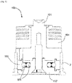
fig.1 ] est une vue schématique en coupe transversale d'un dispositif de préhension de préformes selon l'art antérieur ; - [
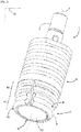
fig.2 ] est une vue en perspective d'un dispositif de préhension de préformes selon l'invention ; - [
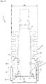
fig.3 ] est une vue en coupe transversale du dispositif de préhension de préformes selon l'invention ; - [
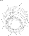
fig.4 ] est une vue en perspective de dessous d'un embout de dispositif de préhension de préformes selon l'invention, selon une première forme de réalisation ; - [
fig.5 ] est une vue en perspective de dessous d'un embout du dispositif de préhension de préforme selon l'invention, selon une deuxième forme de réalisation. - Tel qu'illustré sur la
figure 1 , un dispositif 100 de préhension de préforme 2 selon l'art antérieur comprend un mandrin 101, un support 102 monté à une première extrémité du mandrin 101, des moyens de contact 103 par friction avec une préforme 2 solidaire du support 102 et un radiateur 104 solidaire du mandrin 101. - Plus particulièrement, les moyens de contact 103 par friction sont formés d'une bague montée entre le mandrin 101 d'une part et le support 102 d'autre part.
- La bague comprend plusieurs secteurs angulaires.
- Chaque secteur angulaire est monté entre le mandrin 101 et l'embout 102 de manière à venir compresser radialement des joints 105 toriques permettant d'écarter radialement vers l'extérieur les secteurs de la bague pour forcer le contact par friction de la bague avec l'intérieur d'un col des préformes 2.
- En fonctionnement, le dispositif 100 de préhension est monté à force dans le col des préformes 2.
- Plus précisément, le support 102 est inséré dans le col des préformes 2, de sorte que les moyens de contact 103 par friction soient repoussés radialement vers le mandrin 101 et que les joints toriques 105, par réaction, repoussent les secteurs de la bague contre le col de la préforme 2 pour la maintenir par friction.
- Un tel fonctionnement engendre ainsi des efforts importants du dispositif 100 de préhension sur les préformes 2 lors de la préhension et du relâchement des préformes 2.
- En outre, le support 102, lors de la chauffe des préformes 2, monte en température et ne peut être refroidi que par son contact avec le radiateur 104 du dispositif 100 de préhension.
- Aussi, au fur et à mesure des cycles, le support 102 monte en température, ce qui empêche son bon refroidissement, et peut, à terme, engendrer des dégâts sur la préforme 2, et plus particulièrement une déformation du col de la préforme 2 qui peut empêcher la mise en place d'un bouchon sur le récipient formé. En outre, un mauvais refroidissement pourrait engendrer des dégâts sur la machine de fabrication des récipients, par exemple lié à un mauvais dévêtissage des préformes en sortie de chauffe.
- En référence aux
figures 2 à 5 , un dispositif 1 de préhension de préformes 2, selon l'invention, est décrit. - Tel qu'illustré sur les
figures 2 et3 , le dispositif 1 de préhension de préformes 2, selon l'invention comprend : - un mandrin 3 définissant un axe X de rotation des préformes 2 ;
- un embout 4 monté à une première extrémité du mandrin 3 et présentant une partie pénétrante 41 dans le col des préformes 2 ;
- des moyens de contact 5 par friction avec la préforme 2, solidaire de l'embout 4 ;
- un radiateur 6 solidaire du mandrin 3 et destiné à venir au contact de l'embout 4.
- Le dispositif 1 de préhension selon l'invention diffère de celui de l'art antérieur en ce que l'embout 4 comprend également une partie de refroidissement 42 prolongeant axialement la partie pénétrante 41.
- Plus précisément, tel que cela est visible sur les
figures 2 ,3 ,4 et5 , la partie de refroidissement 42 présente au moins un relief 7 d'échange thermique au contact d'un air ambiant. - Selon le présent mode de réalisation, la partie de refroidissement comprend au moins deux reliefs 7 espacés axialement l'un de l'autre.
- Le, ou chaque relief 7, est formé d'une ailette annulaire, ou quasiment annulaire, ou en arc de cercle qui s'étend radialement autour du mandrin 3.
- Tel que cela est illustré par la
figure 3 , l'un au moins des reliefs 7 de la partie de refroidissement 42 présente une dimension hors-tout supérieure à une dimension hors-tout de la partie pénétrante 41. - Plus précisément, la partie pénétrante 41 de l'embout 4 présente un premier diamètre D1 inférieur au diamètre D2 de l'un au moins des reliefs 7 de la partie de refroidissement 42.
- Cela permet, premièrement, de pouvoir assurer le refroidissement de l'embout 4 et, deuxièmement, de former une butée en enfoncement de la partie pénétrante 41 dans le col des préformes 2.
- En référence aux
figures 2 ,3 ,4 et5 , l'embout 4 présente deux reliefs 7 espacés axialement l'un de l'autre, chaque relief 7 présentant un diamètre D2 identique à l'autre. - Ainsi, les deux reliefs 7 présentent un diamètre hors-tout supérieure au diamètre hors-tout de la partie pénétrante 41, ce qui permet d'augmenter la surface de refroidissement de l'embout 4 au contact de l'air.
- Tel qu'illustré sur la
figure 3 , l'embout 4 est monté sur le mandrin 3 via une paire de joints toriques 8. Les joints toriques 8 sont en l'espèce des éléments élastiquement déformables. - Plus particulièrement, le mandrin 3 présente, au niveau de sa première extrémité, deux gorges 9 annulaires espacées axialement l'une de l'autre à l'intérieur desquelles sont partiellement reçus des joints toriques 8.
- Plus précisément, un joint torique 8 est reçu partiellement dans chacune des gorges 9 annulaires.
- Cela permet, comme il sera décrit ci-après, de favoriser le maintien par friction des préformes 2 sur l'embout 4, mais également de centrer et de maintenir en position l'embout 4 sur le mandrin 3.
- Par ailleurs, tel qu'illustré sur la
figure 3 , à sa première extrémité, le mandrin 3 présente un épaulement 10 destiné à former une butée en translation de l'embout 4 sur le mandrin 3. - Plus particulièrement, l'épaulement 10 du mandrin 3 présente une rainure 11 annulaire dans laquelle est reçu un bourrelet 12 annulaire porté par la partie pénétrante 41 de l'embout 4.
- La coopération entre le bourrelet 12 annulaire et la rainure 11 annulaire permet, en complément de l'action des joints toriques 8, de maintenir centré l'embout 4 sur le mandrin 3, notamment lors de sa rotation, mais également de guider en translation l'embout 4 sur le mandrin 3.
- Les moyens de contact 5 par friction, tel qu'illustré sur les
figures 2 ,3 ,4 et5 , sont intégrés à la partie pénétrante 41 de l'embout 4 et se présentent sous la forme d'au moins une saillie radiale. - Plus particulièrement, les moyens de contact 5 par friction se présentent sous la forme de deux saillies radiales espacées axialement l'une de l'autre et formant toutes les deux un ensemble de vagues.
- Tel que cela est illustré sur la vue en coupe de la
figure 3 , chaque saillie radiale des moyens de contact 5 par friction présente un diamètre identique. - Toutefois, l'une des saillies radiales pourrait présenter un diamètre inférieur à l'autre. De préférence, la saillie radiale la plus éloignée du radiateur 6 présente un diamètre inférieur à la saillie radiale la plus proche du radiateur 6.
- Tel que cela est visible sur les
figures 2 et3 , le mandrin 3 présente, à sa première extrémité, une surface pleine 13 réfléchissante destinée à former des moyens de réflexion d'un rayonnement lumineux de source lumineuse d'une unité de chauffe 14. - La surface pleine 13 réfléchissante permet ainsi d'éviter un échauffement du mandrin 3 et de l'embout 4 par le rayonnement lumineux émis par les sources de rayonnement lumineux de l'unité de chauffe 14.
- Ainsi, grâce à la présence de cette surface pleine 13 réfléchissante, le refroidissement de l'embout 4 ne nécessite pas d'être intense.
- Dès lors, en fonctionnement, malgré un temps de présence hors de l'unité de chauffe 14 réduit, notamment en conséquence de l'augmentation des cadences de production, la simple présence des reliefs 7, sous forme d'ailettes, de la partie de refroidissement 42 permet que, au contact de l'air ambiant, l'embout 4 soit convenablement refroidi pour éviter tout endommagement des préformes 2.
- Les reliefs 7, sous forme, d'ailettes permettent le refroidissement de l'embout 4 lors de la chauffe, grâce à un air forcé, notamment par ventilation.
- Préférentiellement, la partie de refroidissement 42 et la partie pénétrante 41 de l'embout 4 forment un ensemble monobloc.
- Autrement dit, la partie pénétrante 41 et la partie de refroidissement 42 de l'embout 4 peuvent être fabriquées indépendamment l'une de l'autre mais sont assemblées de manière définitive en vue d'être utilisées sur le dispositif 1 de préhension.
- Plus particulièrement, l'embout 4 du dispositif 1 de préhension selon l'invention est réalisé en acier inoxydable ou en aluminium spécifique, notamment pour des raisons de contact avec un récipient destiné à contenir un produit alimentaire.
- Ainsi, l'assemblage de la partie pénétrante 41 avec la partie de refroidissement 42 de l'embout 4 peut être assuré par soudage par exemple.
- Selon un mode de réalisation avantageux, la partie pénétrante 41 de l'embout 4 et la partie de refroidissement 42 sont venues de matières l'une avec l'autre.
- Autrement dit, la partie pénétrante 41 et la partie de refroidissement 42 de l'embout 4 sont par exemple obtenues par moulage ou par usinage.
- Selon une première forme de réalisation, tel qu'illustré sur la
figure 4 , l'embout 4 comprend au moins deux secteurs angulaires 4a, 4b. - Plus précisément, l'embout 4 comprend un premier secteur angulaire 4a, un deuxième secteur angulaire 4b et un troisième secteur angulaire 4c s'étendant chacun sur approximativement 120 degrés.
- Les secteurs angulaires 4a, 4b, 4c sont maintenus sur le mandrin 3 par la coopération entre la rainure 11 annulaire et le bourrelet 12 annulaire d'une part, et par leur insertion dans un épaulement 61 ménagé dans le radiateur 6 d'autre part.
- Le radiateur 6 est quant à lui fixe sur le mandrin 3, ce qui permet d'autoriser un déplacement de l'embout 4 entre l'épaulement 10 du mandrin 3 et le radiateur 6.
- Selon une deuxième forme de réalisation illustrée sur la
figure 5 , l'embout 4 est formé d'un unique secteur angulaire présentant une fente 4d pour autoriser une déformation élastique de l'embout 4, notamment lors du vétissage et du dévétissage, c'est-à-dire lors de la préhension et du relâchement d'une préforme 2. - Le secteur angulaire unique est maintenu sur le mandrin 3 par la coopération entre la rainure 11 annulaire et le bourrelet 12 annulaire d'une part, et son insertion dans l'épaulement 61 ménagé dans le radiateur 6 d'autre part.
- Le dispositif 1 de préhension qui vient d'être décrit, notamment la présence de la partie de refroidissement 42 permet d'assurer un refroidissement adéquat de l'embout 4 entre la chauffe de deux préformes 2, cela au bénéfice de l'intégrité du col des préformes.
- En effet, la présente des reliefs 7 sur la partie de refroidissement 42 de l'embout 4 permet de faciliter les échanges thermiques entre l'embout 4 et l'air ambiant, et donc le refroidissement de l'embout 4.
Claims (12)
- Dispositif (1) de préhension de préformes (2) pour unité de chauffe (14), comprenant :- un mandrin (3) définissant un axe (X) de rotation des préformes (2) ;- un embout (4) monté à une première extrémité du mandrin (3) et présentant une partie pénétrante (41) dans le col des préformes (2) ;- des moyens de contact (5) par friction avec la préforme (2), solidaires de l'embout (4),- un radiateur (6) solidaire du mandrin (3) et destiné à venir au contact de l'embout (4),caractérisé en ce que l'embout (4) comprend également une partie de refroidissement (42) dans le prolongement axial de la partie pénétrante (41), la partie de refroidissement (42) présentant au moins un relief (7) d'échange thermique au contact d'un air ambiant, et en ce que l'embout (4) est monté mobile sur le mandrin (3).
- Dispositif (1) selon la revendication précédente, caractérisé en ce que la partie de refroidissement (42) comprend au moins deux reliefs (7) espacés axialement l'un de l'autre.
- Dispositif (1) selon l'une quelconque des revendications précédentes, caractérisé en ce que le ou chaque relief (7) est formé d'une ailette annulaire qui s'étend radialement autour du mandrin (3).
- Dispositif (1) selon la revendication précédente, caractérisé en ce que l'un au moins des reliefs (7) de la partie de refroidissement (42) présente une dimension hors tout supérieure à une dimension hors-tout de la partie pénétrante (41).
- Dispositif selon l'une quelconque des revendications précédentes, caractérisé en ce que la partie pénétrante (41) et la partie de refroidissement (42) de l'embout (4) forment un ensemble monobloc.
- Dispositif (1) selon l'une quelconque des revendications précédentes, caractérisé en ce que l'embout (4) comprend au moins deux secteurs angulaires pour chacun desquels la partie pénétrante (41) et la partie de refroidissement (42) de l'embout (4) sont venues de matière l'une avec l'autre.
- Dispositif (1) selon l'une quelconque des revendications 1 à 5, caractérisé en ce que la patrie pénétrante (41) et la partie de refroidissement (42) de l'embout (4) sont venues de matière l'une avec l'autre.
- Dispositif (1) selon l'une quelconque des revendications précédentes, caractérisé en ce que les moyens de contact (5) par friction sont intégrés à la partie pénétrante (41) et se présentent sous la forme d'au moins une saillie radiale.
- Dispositif (1) selon l'une quelconque des revendications précédentes, caractérisé en ce que le mandrin (3) présente une surface pleine (13) réfléchissante à sa première extrémité, destinée à former des moyens de réflexion d'un rayonnement lumineux de sources lumineuses d'une unité de chauffe (14).
- Dispositif (1) selon l'une quelconque des revendications précédentes, caractérisé en ce que le mandrin (3) présente, à sa première extrémité, un épaulement (10) destiné à former une butée en translation de l'embout (4) sur le mandrin (3).
- Dispositif (1) selon la revendication précédente caractérisé en ce que l'épaulement (10) du mandrin (3) présente une rainure (11) annulaire dans laquelle est reçu un bourrelet (12) annulaire porté par la partie pénétrante (41) de l'embout (4).
- Unité de chauffe (14) de préformes (2) comprenant au moins un dispositif (1) de préhension de préformes selon l'une quelconque des revendications précédentes.
Applications Claiming Priority (1)
| Application Number | Priority Date | Filing Date | Title |
|---|---|---|---|
| FR2003248A FR3108868B1 (fr) | 2020-04-01 | 2020-04-01 | Dispositif de préhension de préformes pour unité de chauffe |
Publications (2)
| Publication Number | Publication Date |
|---|---|
| EP3888883A1 true EP3888883A1 (fr) | 2021-10-06 |
| EP3888883B1 EP3888883B1 (fr) | 2023-02-15 |
Family
ID=70804809
Family Applications (1)
| Application Number | Title | Priority Date | Filing Date |
|---|---|---|---|
| EP21165467.8A Active EP3888883B1 (fr) | 2020-04-01 | 2021-03-29 | Dispositif de prehension de preformes pour unite de chauffe |
Country Status (4)
| Country | Link |
|---|---|
| US (1) | US11633900B2 (fr) |
| EP (1) | EP3888883B1 (fr) |
| CN (1) | CN113492516B (fr) |
| FR (1) | FR3108868B1 (fr) |
Families Citing this family (1)
| Publication number | Priority date | Publication date | Assignee | Title |
|---|---|---|---|---|
| FR3136395B1 (fr) * | 2022-06-10 | 2024-07-05 | Sidel Participations | Station de chauffage de preformes comportant des moyens de refroidissement |
Citations (4)
| Publication number | Priority date | Publication date | Assignee | Title |
|---|---|---|---|---|
| US8992208B2 (en) * | 2011-09-09 | 2015-03-31 | Khs Corpoplast Gmbh | Device for transporting preforms for blow molding containers |
| DE102014017546A1 (de) * | 2014-11-28 | 2016-06-02 | Khs Corpoplast Gmbh | Vorrichtung zum Haltern von Werkstücken, Maschine mit einer solchen Vorrichtung und Verwendung einer solchen Vorrichtung |
| EP3228438A1 (fr) | 2016-04-05 | 2017-10-11 | Sidel Participations | Dispositif de prehension de corps creux presentant une capacite accrue d'evacuation de la chaleur |
| DE102017124186A1 (de) * | 2017-10-17 | 2019-04-18 | Khs Corpoplast Gmbh | Schnellwechseldorn mit aktiver Preformklemmung |
Family Cites Families (6)
| Publication number | Priority date | Publication date | Assignee | Title |
|---|---|---|---|---|
| FR2789932B1 (fr) * | 1999-02-18 | 2001-07-20 | Sidel Sa | Dispositif de transport de preformes comportant des moyens de prehension perfectionnes et four comportant un tel dispositif |
| US20030034231A1 (en) * | 2001-08-20 | 2003-02-20 | Alden Palisca | Preform carrier |
| FR2882963B1 (fr) * | 2005-03-11 | 2009-12-18 | Sidel Sa | Dispositif de transport d'une preforme dans un four, tournette et machine de conditionnement thermique pour installation de soufflage de recipients en materiau thermoplastique comprenant un tel dispositif |
| DE102005032403A1 (de) * | 2005-07-12 | 2007-01-25 | Sig Technology Ltd. | Verfahren und Vorrichtung zur Blasformung von Behältern |
| CN102153038B (zh) * | 2011-01-28 | 2012-11-21 | 广州达意隆包装机械股份有限公司 | 一种夹胚头 |
| FR3011498B1 (fr) * | 2013-10-09 | 2016-07-29 | Sidel Participations | Dispostif de prehension d'un recipient comportant un nez dans lequel des mors a expansion sont maintenus circonferentiellement en position |
-
2020
- 2020-04-01 FR FR2003248A patent/FR3108868B1/fr active Active
-
2021
- 2021-03-29 EP EP21165467.8A patent/EP3888883B1/fr active Active
- 2021-03-31 US US17/219,774 patent/US11633900B2/en active Active
- 2021-04-01 CN CN202110353298.4A patent/CN113492516B/zh active Active
Patent Citations (4)
| Publication number | Priority date | Publication date | Assignee | Title |
|---|---|---|---|---|
| US8992208B2 (en) * | 2011-09-09 | 2015-03-31 | Khs Corpoplast Gmbh | Device for transporting preforms for blow molding containers |
| DE102014017546A1 (de) * | 2014-11-28 | 2016-06-02 | Khs Corpoplast Gmbh | Vorrichtung zum Haltern von Werkstücken, Maschine mit einer solchen Vorrichtung und Verwendung einer solchen Vorrichtung |
| EP3228438A1 (fr) | 2016-04-05 | 2017-10-11 | Sidel Participations | Dispositif de prehension de corps creux presentant une capacite accrue d'evacuation de la chaleur |
| DE102017124186A1 (de) * | 2017-10-17 | 2019-04-18 | Khs Corpoplast Gmbh | Schnellwechseldorn mit aktiver Preformklemmung |
Also Published As
| Publication number | Publication date |
|---|---|
| US20210308931A1 (en) | 2021-10-07 |
| CN113492516B (zh) | 2026-03-31 |
| EP3888883B1 (fr) | 2023-02-15 |
| FR3108868A1 (fr) | 2021-10-08 |
| CN113492516A (zh) | 2021-10-12 |
| US11633900B2 (en) | 2023-04-25 |
| FR3108868B1 (fr) | 2024-05-10 |
Similar Documents
| Publication | Publication Date | Title |
|---|---|---|
| EP1165303B1 (fr) | Dispositif de transport de preformes comportant des moyens de prehension perfectionnes | |
| EP1880825B1 (fr) | Dispositif de support individuel d'un récipient pourvu d'un col et installation pourvue de dispositifs de transport avec un tel dispositif de support | |
| FR2972671A1 (fr) | Dispositif de transfert comportant une pince de prehension perfectionnee | |
| EP3228438B1 (fr) | Dispositif de prehension de corps creux presentant une capacite accrue d'evacuation de la chaleur | |
| EP3888883B1 (fr) | Dispositif de prehension de preformes pour unite de chauffe | |
| EP0253721A1 (fr) | Manchon thermorétractable comportant des moyens pour contrôler son chauffage uniforme, et procédé de fabrication de ce manchon | |
| EP1855868B1 (fr) | Dispositif de prehension de corps creux par leur col et installation de transport de corps creux equipee de tels dispositifs | |
| FR3143909A1 (fr) | Machine électrique, en particulier moteur électrique | |
| EP0629484B1 (fr) | Procédé et agencement pour positionner un récipient ou une préforme de récipient avec une orientation angulaire prédéterminée sur un mandrin de support | |
| EP0000801B1 (fr) | Procédé pour la production de corps creux orientés | |
| FR2934568A1 (fr) | Procede de traitement d'un contenant a paroi mince en matiere plastique, rempli a chaud et dispositif associe | |
| EP2961437B1 (fr) | Procede de decontamination par irradiation de l'interieur d'une preforme | |
| FR3109284A1 (fr) | Mécanisme pour un réceptacle d’application d’un produit cosmétique, réceptacle comportant un tel mécanisme et procédé d’obtention d’un tel mécanisme | |
| EP1388709A1 (fr) | Procédé de réalisation d'un dispositif d'éclairage ou de signalisation, et dispositif d'éclairage ou de signalisation obtenu par ce procédé | |
| EP1420935A1 (fr) | Procede et installation pour thermoformer des recipients | |
| FR2935532A1 (fr) | Procede de fabrication d'un emballage pour le transport et/ou stockage de matieres nucleaires, utilisant le phenomene de retrait de soudage. | |
| EP2401132B1 (fr) | Dispositif de préhension d'un corps creux par son col | |
| WO2020128324A1 (fr) | Procédé et système de traitement d'un flux de préformes en matière thermoplastique pour en orienter angulairement chacune des préformes dans une position de référence | |
| EP4610022A1 (fr) | Unité de traitement thermique de préformes comprenant un élément de blocage d'un rayonnement vers le col des préformes | |
| FR2942740A1 (fr) | Systeme d'orientation des emetteurs infrarouges pour le chauffage de preformes en matiere plastique | |
| FR2917328A1 (fr) | Moule pour la fabrication de recipients a poignee | |
| FR3144540A1 (fr) | Dispositif de montage et/ou de démontage de nez de tournette et application à une unité de conditionnement thermique de préformes. | |
| EP0461017B1 (fr) | Procédé et dispositif de fabrication d'un fût et fût obtenu selon ce procédé | |
| WO2026021856A1 (fr) | Système de formation d'au moins un bourrelet sur une canalisation de circuit de fluide et procédé associé | |
| FR3004985A1 (fr) | "procede de faconnage d'une preforme chaude par estampage et dispositif pour sa mise en oeuvre" |
Legal Events
| Date | Code | Title | Description |
|---|---|---|---|
| PUAI | Public reference made under article 153(3) epc to a published international application that has entered the european phase |
Free format text: ORIGINAL CODE: 0009012 |
|
| STAA | Information on the status of an ep patent application or granted ep patent |
Free format text: STATUS: THE APPLICATION HAS BEEN PUBLISHED |
|
| AK | Designated contracting states |
Kind code of ref document: A1 Designated state(s): AL AT BE BG CH CY CZ DE DK EE ES FI FR GB GR HR HU IE IS IT LI LT LU LV MC MK MT NL NO PL PT RO RS SE SI SK SM TR |
|
| STAA | Information on the status of an ep patent application or granted ep patent |
Free format text: STATUS: REQUEST FOR EXAMINATION WAS MADE |
|
| 17P | Request for examination filed |
Effective date: 20220406 |
|
| RBV | Designated contracting states (corrected) |
Designated state(s): AL AT BE BG CH CY CZ DE DK EE ES FI FR GB GR HR HU IE IS IT LI LT LU LV MC MK MT NL NO PL PT RO RS SE SI SK SM TR |
|
| GRAP | Despatch of communication of intention to grant a patent |
Free format text: ORIGINAL CODE: EPIDOSNIGR1 |
|
| STAA | Information on the status of an ep patent application or granted ep patent |
Free format text: STATUS: GRANT OF PATENT IS INTENDED |
|
| RIC1 | Information provided on ipc code assigned before grant |
Ipc: B29L 31/00 20060101ALN20220901BHEP Ipc: B29K 67/00 20060101ALN20220901BHEP Ipc: B29C 49/64 20060101ALN20220901BHEP Ipc: B29C 49/06 20060101ALN20220901BHEP Ipc: B29C 49/42 20060101AFI20220901BHEP |
|
| RIC1 | Information provided on ipc code assigned before grant |
Ipc: B29L 31/00 20060101ALN20220914BHEP Ipc: B29K 67/00 20060101ALN20220914BHEP Ipc: B29C 49/64 20060101ALN20220914BHEP Ipc: B29C 49/06 20060101ALN20220914BHEP Ipc: B29C 49/42 20060101AFI20220914BHEP |
|
| INTG | Intention to grant announced |
Effective date: 20220928 |
|
| GRAS | Grant fee paid |
Free format text: ORIGINAL CODE: EPIDOSNIGR3 |
|
| GRAA | (expected) grant |
Free format text: ORIGINAL CODE: 0009210 |
|
| STAA | Information on the status of an ep patent application or granted ep patent |
Free format text: STATUS: THE PATENT HAS BEEN GRANTED |
|
| AK | Designated contracting states |
Kind code of ref document: B1 Designated state(s): AL AT BE BG CH CY CZ DE DK EE ES FI FR GB GR HR HU IE IS IT LI LT LU LV MC MK MT NL NO PL PT RO RS SE SI SK SM TR |
|
| REG | Reference to a national code |
Ref country code: CH Ref legal event code: EP Ref country code: GB Ref legal event code: FG4D Free format text: NOT ENGLISH |
|
| REG | Reference to a national code |
Ref country code: DE Ref legal event code: R096 Ref document number: 602021001387 Country of ref document: DE |
|
| REG | Reference to a national code |
Ref country code: AT Ref legal event code: REF Ref document number: 1548014 Country of ref document: AT Kind code of ref document: T Effective date: 20230315 Ref country code: IE Ref legal event code: FG4D Free format text: LANGUAGE OF EP DOCUMENT: FRENCH |
|
| REG | Reference to a national code |
Ref country code: LT Ref legal event code: MG9D |
|
| P01 | Opt-out of the competence of the unified patent court (upc) registered |
Effective date: 20230403 |
|
| REG | Reference to a national code |
Ref country code: NL Ref legal event code: MP Effective date: 20230215 |
|
| REG | Reference to a national code |
Ref country code: AT Ref legal event code: MK05 Ref document number: 1548014 Country of ref document: AT Kind code of ref document: T Effective date: 20230215 |
|
| PG25 | Lapsed in a contracting state [announced via postgrant information from national office to epo] |
Ref country code: RS Free format text: LAPSE BECAUSE OF FAILURE TO SUBMIT A TRANSLATION OF THE DESCRIPTION OR TO PAY THE FEE WITHIN THE PRESCRIBED TIME-LIMIT Effective date: 20230215 Ref country code: PT Free format text: LAPSE BECAUSE OF FAILURE TO SUBMIT A TRANSLATION OF THE DESCRIPTION OR TO PAY THE FEE WITHIN THE PRESCRIBED TIME-LIMIT Effective date: 20230615 Ref country code: NO Free format text: LAPSE BECAUSE OF FAILURE TO SUBMIT A TRANSLATION OF THE DESCRIPTION OR TO PAY THE FEE WITHIN THE PRESCRIBED TIME-LIMIT Effective date: 20230515 Ref country code: NL Free format text: LAPSE BECAUSE OF FAILURE TO SUBMIT A TRANSLATION OF THE DESCRIPTION OR TO PAY THE FEE WITHIN THE PRESCRIBED TIME-LIMIT Effective date: 20230215 Ref country code: LV Free format text: LAPSE BECAUSE OF FAILURE TO SUBMIT A TRANSLATION OF THE DESCRIPTION OR TO PAY THE FEE WITHIN THE PRESCRIBED TIME-LIMIT Effective date: 20230215 Ref country code: LT Free format text: LAPSE BECAUSE OF FAILURE TO SUBMIT A TRANSLATION OF THE DESCRIPTION OR TO PAY THE FEE WITHIN THE PRESCRIBED TIME-LIMIT Effective date: 20230215 Ref country code: HR Free format text: LAPSE BECAUSE OF FAILURE TO SUBMIT A TRANSLATION OF THE DESCRIPTION OR TO PAY THE FEE WITHIN THE PRESCRIBED TIME-LIMIT Effective date: 20230215 Ref country code: ES Free format text: LAPSE BECAUSE OF FAILURE TO SUBMIT A TRANSLATION OF THE DESCRIPTION OR TO PAY THE FEE WITHIN THE PRESCRIBED TIME-LIMIT Effective date: 20230215 Ref country code: AT Free format text: LAPSE BECAUSE OF FAILURE TO SUBMIT A TRANSLATION OF THE DESCRIPTION OR TO PAY THE FEE WITHIN THE PRESCRIBED TIME-LIMIT Effective date: 20230215 |
|
| PG25 | Lapsed in a contracting state [announced via postgrant information from national office to epo] |
Ref country code: SE Free format text: LAPSE BECAUSE OF FAILURE TO SUBMIT A TRANSLATION OF THE DESCRIPTION OR TO PAY THE FEE WITHIN THE PRESCRIBED TIME-LIMIT Effective date: 20230215 Ref country code: PL Free format text: LAPSE BECAUSE OF FAILURE TO SUBMIT A TRANSLATION OF THE DESCRIPTION OR TO PAY THE FEE WITHIN THE PRESCRIBED TIME-LIMIT Effective date: 20230215 Ref country code: IS Free format text: LAPSE BECAUSE OF FAILURE TO SUBMIT A TRANSLATION OF THE DESCRIPTION OR TO PAY THE FEE WITHIN THE PRESCRIBED TIME-LIMIT Effective date: 20230615 Ref country code: GR Free format text: LAPSE BECAUSE OF FAILURE TO SUBMIT A TRANSLATION OF THE DESCRIPTION OR TO PAY THE FEE WITHIN THE PRESCRIBED TIME-LIMIT Effective date: 20230516 Ref country code: FI Free format text: LAPSE BECAUSE OF FAILURE TO SUBMIT A TRANSLATION OF THE DESCRIPTION OR TO PAY THE FEE WITHIN THE PRESCRIBED TIME-LIMIT Effective date: 20230215 |
|
| PG25 | Lapsed in a contracting state [announced via postgrant information from national office to epo] |
Ref country code: SM Free format text: LAPSE BECAUSE OF FAILURE TO SUBMIT A TRANSLATION OF THE DESCRIPTION OR TO PAY THE FEE WITHIN THE PRESCRIBED TIME-LIMIT Effective date: 20230215 Ref country code: RO Free format text: LAPSE BECAUSE OF FAILURE TO SUBMIT A TRANSLATION OF THE DESCRIPTION OR TO PAY THE FEE WITHIN THE PRESCRIBED TIME-LIMIT Effective date: 20230215 Ref country code: EE Free format text: LAPSE BECAUSE OF FAILURE TO SUBMIT A TRANSLATION OF THE DESCRIPTION OR TO PAY THE FEE WITHIN THE PRESCRIBED TIME-LIMIT Effective date: 20230215 Ref country code: DK Free format text: LAPSE BECAUSE OF FAILURE TO SUBMIT A TRANSLATION OF THE DESCRIPTION OR TO PAY THE FEE WITHIN THE PRESCRIBED TIME-LIMIT Effective date: 20230215 Ref country code: CZ Free format text: LAPSE BECAUSE OF FAILURE TO SUBMIT A TRANSLATION OF THE DESCRIPTION OR TO PAY THE FEE WITHIN THE PRESCRIBED TIME-LIMIT Effective date: 20230215 |
|
| REG | Reference to a national code |
Ref country code: DE Ref legal event code: R097 Ref document number: 602021001387 Country of ref document: DE |
|
| PG25 | Lapsed in a contracting state [announced via postgrant information from national office to epo] |
Ref country code: SK Free format text: LAPSE BECAUSE OF FAILURE TO SUBMIT A TRANSLATION OF THE DESCRIPTION OR TO PAY THE FEE WITHIN THE PRESCRIBED TIME-LIMIT Effective date: 20230215 |
|
| REG | Reference to a national code |
Ref country code: BE Ref legal event code: MM Effective date: 20230331 |
|
| PLBE | No opposition filed within time limit |
Free format text: ORIGINAL CODE: 0009261 |
|
| STAA | Information on the status of an ep patent application or granted ep patent |
Free format text: STATUS: NO OPPOSITION FILED WITHIN TIME LIMIT |
|
| PG25 | Lapsed in a contracting state [announced via postgrant information from national office to epo] |
Ref country code: LU Free format text: LAPSE BECAUSE OF NON-PAYMENT OF DUE FEES Effective date: 20230329 |
|
| PG25 | Lapsed in a contracting state [announced via postgrant information from national office to epo] |
Ref country code: MC Free format text: LAPSE BECAUSE OF FAILURE TO SUBMIT A TRANSLATION OF THE DESCRIPTION OR TO PAY THE FEE WITHIN THE PRESCRIBED TIME-LIMIT Effective date: 20230215 |
|
| REG | Reference to a national code |
Ref country code: IE Ref legal event code: MM4A |
|
| 26N | No opposition filed |
Effective date: 20231116 |
|
| PG25 | Lapsed in a contracting state [announced via postgrant information from national office to epo] |
Ref country code: SI Free format text: LAPSE BECAUSE OF FAILURE TO SUBMIT A TRANSLATION OF THE DESCRIPTION OR TO PAY THE FEE WITHIN THE PRESCRIBED TIME-LIMIT Effective date: 20230215 Ref country code: MC Free format text: LAPSE BECAUSE OF FAILURE TO SUBMIT A TRANSLATION OF THE DESCRIPTION OR TO PAY THE FEE WITHIN THE PRESCRIBED TIME-LIMIT Effective date: 20230215 Ref country code: IE Free format text: LAPSE BECAUSE OF NON-PAYMENT OF DUE FEES Effective date: 20230329 |
|
| PG25 | Lapsed in a contracting state [announced via postgrant information from national office to epo] |
Ref country code: BE Free format text: LAPSE BECAUSE OF NON-PAYMENT OF DUE FEES Effective date: 20230331 |
|
| REG | Reference to a national code |
Ref country code: CH Ref legal event code: PL |
|
| PG25 | Lapsed in a contracting state [announced via postgrant information from national office to epo] |
Ref country code: BG Free format text: LAPSE BECAUSE OF FAILURE TO SUBMIT A TRANSLATION OF THE DESCRIPTION OR TO PAY THE FEE WITHIN THE PRESCRIBED TIME-LIMIT Effective date: 20230215 |
|
| PG25 | Lapsed in a contracting state [announced via postgrant information from national office to epo] |
Ref country code: BG Free format text: LAPSE BECAUSE OF FAILURE TO SUBMIT A TRANSLATION OF THE DESCRIPTION OR TO PAY THE FEE WITHIN THE PRESCRIBED TIME-LIMIT Effective date: 20230215 |
|
| PG25 | Lapsed in a contracting state [announced via postgrant information from national office to epo] |
Ref country code: CH Free format text: LAPSE BECAUSE OF NON-PAYMENT OF DUE FEES Effective date: 20240331 |
|
| PG25 | Lapsed in a contracting state [announced via postgrant information from national office to epo] |
Ref country code: CY Free format text: LAPSE BECAUSE OF FAILURE TO SUBMIT A TRANSLATION OF THE DESCRIPTION OR TO PAY THE FEE WITHIN THE PRESCRIBED TIME-LIMIT; INVALID AB INITIO Effective date: 20210329 |
|
| PG25 | Lapsed in a contracting state [announced via postgrant information from national office to epo] |
Ref country code: HU Free format text: LAPSE BECAUSE OF FAILURE TO SUBMIT A TRANSLATION OF THE DESCRIPTION OR TO PAY THE FEE WITHIN THE PRESCRIBED TIME-LIMIT; INVALID AB INITIO Effective date: 20210329 |
|
| GBPC | Gb: european patent ceased through non-payment of renewal fee |
Effective date: 20250329 |
|
| PG25 | Lapsed in a contracting state [announced via postgrant information from national office to epo] |
Ref country code: TR Free format text: LAPSE BECAUSE OF FAILURE TO SUBMIT A TRANSLATION OF THE DESCRIPTION OR TO PAY THE FEE WITHIN THE PRESCRIBED TIME-LIMIT Effective date: 20230215 |
|
| PG25 | Lapsed in a contracting state [announced via postgrant information from national office to epo] |
Ref country code: GB Free format text: LAPSE BECAUSE OF NON-PAYMENT OF DUE FEES Effective date: 20250329 |
|
| PGFP | Annual fee paid to national office [announced via postgrant information from national office to epo] |
Ref country code: DE Payment date: 20260219 Year of fee payment: 6 |
|
| PGFP | Annual fee paid to national office [announced via postgrant information from national office to epo] |
Ref country code: IT Payment date: 20260219 Year of fee payment: 6 |
|
| PGFP | Annual fee paid to national office [announced via postgrant information from national office to epo] |
Ref country code: FR Payment date: 20260220 Year of fee payment: 6 |
|
| PG25 | Lapsed in a contracting state [announced via postgrant information from national office to epo] |
Ref country code: CH Free format text: THE PATENT HAS BEEN ANNULLED BY A DECISION OF A NATIONAL AUTHORITY Effective date: 20240331 |
|
| PG25 | Lapsed in a contracting state [announced via postgrant information from national office to epo] |
Ref country code: MT Free format text: LAPSE BECAUSE OF NON-PAYMENT OF DUE FEES Effective date: 20230329 |