EP3888823A1 - Fabrication table and fabricating apparatus - Google Patents
Fabrication table and fabricating apparatus Download PDFInfo
- Publication number
- EP3888823A1 EP3888823A1 EP21165447.0A EP21165447A EP3888823A1 EP 3888823 A1 EP3888823 A1 EP 3888823A1 EP 21165447 A EP21165447 A EP 21165447A EP 3888823 A1 EP3888823 A1 EP 3888823A1
- Authority
- EP
- European Patent Office
- Prior art keywords
- fabrication
- powder
- separable portion
- supporter
- chamber
- Prior art date
- Legal status (The legal status is an assumption and is not a legal conclusion. Google has not performed a legal analysis and makes no representation as to the accuracy of the status listed.)
- Withdrawn
Links
Images



Classifications
-
- B—PERFORMING OPERATIONS; TRANSPORTING
- B33—ADDITIVE MANUFACTURING TECHNOLOGY
- B33Y—ADDITIVE MANUFACTURING, i.e. MANUFACTURING OF THREE-DIMENSIONAL [3D] OBJECTS BY ADDITIVE DEPOSITION, ADDITIVE AGGLOMERATION OR ADDITIVE LAYERING, e.g. BY 3D PRINTING, STEREOLITHOGRAPHY OR SELECTIVE LASER SINTERING
- B33Y30/00—Apparatus for additive manufacturing; Details thereof or accessories therefor
-
- B—PERFORMING OPERATIONS; TRANSPORTING
- B29—WORKING OF PLASTICS; WORKING OF SUBSTANCES IN A PLASTIC STATE IN GENERAL
- B29C—SHAPING OR JOINING OF PLASTICS; SHAPING OF MATERIAL IN A PLASTIC STATE, NOT OTHERWISE PROVIDED FOR; AFTER-TREATMENT OF THE SHAPED PRODUCTS, e.g. REPAIRING
- B29C64/00—Additive manufacturing, i.e. manufacturing of three-dimensional [3D] objects by additive deposition, additive agglomeration or additive layering, e.g. by 3D printing, stereolithography or selective laser sintering
- B29C64/40—Structures for supporting 3D objects during manufacture and intended to be sacrificed after completion thereof
-
- B—PERFORMING OPERATIONS; TRANSPORTING
- B22—CASTING; POWDER METALLURGY
- B22F—WORKING METALLIC POWDER; MANUFACTURE OF ARTICLES FROM METALLIC POWDER; MAKING METALLIC POWDER; APPARATUS OR DEVICES SPECIALLY ADAPTED FOR METALLIC POWDER
- B22F10/00—Additive manufacturing of workpieces or articles from metallic powder
- B22F10/10—Formation of a green body
- B22F10/14—Formation of a green body by jetting of binder onto a bed of metal powder
-
- B—PERFORMING OPERATIONS; TRANSPORTING
- B22—CASTING; POWDER METALLURGY
- B22F—WORKING METALLIC POWDER; MANUFACTURE OF ARTICLES FROM METALLIC POWDER; MAKING METALLIC POWDER; APPARATUS OR DEVICES SPECIALLY ADAPTED FOR METALLIC POWDER
- B22F10/00—Additive manufacturing of workpieces or articles from metallic powder
- B22F10/40—Structures for supporting workpieces or articles during manufacture and removed afterwards
- B22F10/43—Structures for supporting workpieces or articles during manufacture and removed afterwards characterised by material
-
- B—PERFORMING OPERATIONS; TRANSPORTING
- B22—CASTING; POWDER METALLURGY
- B22F—WORKING METALLIC POWDER; MANUFACTURE OF ARTICLES FROM METALLIC POWDER; MAKING METALLIC POWDER; APPARATUS OR DEVICES SPECIALLY ADAPTED FOR METALLIC POWDER
- B22F10/00—Additive manufacturing of workpieces or articles from metallic powder
- B22F10/60—Treatment of workpieces or articles after build-up
- B22F10/64—Treatment of workpieces or articles after build-up by thermal means
-
- B—PERFORMING OPERATIONS; TRANSPORTING
- B22—CASTING; POWDER METALLURGY
- B22F—WORKING METALLIC POWDER; MANUFACTURE OF ARTICLES FROM METALLIC POWDER; MAKING METALLIC POWDER; APPARATUS OR DEVICES SPECIALLY ADAPTED FOR METALLIC POWDER
- B22F12/00—Apparatus or devices specially adapted for additive manufacturing; Auxiliary means for additive manufacturing; Combinations of additive manufacturing apparatus or devices with other processing apparatus or devices
- B22F12/30—Platforms or substrates
-
- B—PERFORMING OPERATIONS; TRANSPORTING
- B29—WORKING OF PLASTICS; WORKING OF SUBSTANCES IN A PLASTIC STATE IN GENERAL
- B29C—SHAPING OR JOINING OF PLASTICS; SHAPING OF MATERIAL IN A PLASTIC STATE, NOT OTHERWISE PROVIDED FOR; AFTER-TREATMENT OF THE SHAPED PRODUCTS, e.g. REPAIRING
- B29C64/00—Additive manufacturing, i.e. manufacturing of three-dimensional [3D] objects by additive deposition, additive agglomeration or additive layering, e.g. by 3D printing, stereolithography or selective laser sintering
- B29C64/20—Apparatus for additive manufacturing; Details thereof or accessories therefor
- B29C64/245—Platforms or substrates
-
- B—PERFORMING OPERATIONS; TRANSPORTING
- B33—ADDITIVE MANUFACTURING TECHNOLOGY
- B33Y—ADDITIVE MANUFACTURING, i.e. MANUFACTURING OF THREE-DIMENSIONAL [3D] OBJECTS BY ADDITIVE DEPOSITION, ADDITIVE AGGLOMERATION OR ADDITIVE LAYERING, e.g. BY 3D PRINTING, STEREOLITHOGRAPHY OR SELECTIVE LASER SINTERING
- B33Y10/00—Processes of additive manufacturing
-
- B—PERFORMING OPERATIONS; TRANSPORTING
- B33—ADDITIVE MANUFACTURING TECHNOLOGY
- B33Y—ADDITIVE MANUFACTURING, i.e. MANUFACTURING OF THREE-DIMENSIONAL [3D] OBJECTS BY ADDITIVE DEPOSITION, ADDITIVE AGGLOMERATION OR ADDITIVE LAYERING, e.g. BY 3D PRINTING, STEREOLITHOGRAPHY OR SELECTIVE LASER SINTERING
- B33Y40/00—Auxiliary operations or equipment, e.g. for material handling
- B33Y40/20—Post-treatment, e.g. curing, coating or polishing
-
- B—PERFORMING OPERATIONS; TRANSPORTING
- B22—CASTING; POWDER METALLURGY
- B22F—WORKING METALLIC POWDER; MANUFACTURE OF ARTICLES FROM METALLIC POWDER; MAKING METALLIC POWDER; APPARATUS OR DEVICES SPECIALLY ADAPTED FOR METALLIC POWDER
- B22F2999/00—Aspects linked to processes or compositions used in powder metallurgy
-
- B—PERFORMING OPERATIONS; TRANSPORTING
- B33—ADDITIVE MANUFACTURING TECHNOLOGY
- B33Y—ADDITIVE MANUFACTURING, i.e. MANUFACTURING OF THREE-DIMENSIONAL [3D] OBJECTS BY ADDITIVE DEPOSITION, ADDITIVE AGGLOMERATION OR ADDITIVE LAYERING, e.g. BY 3D PRINTING, STEREOLITHOGRAPHY OR SELECTIVE LASER SINTERING
- B33Y40/00—Auxiliary operations or equipment, e.g. for material handling
-
- Y—GENERAL TAGGING OF NEW TECHNOLOGICAL DEVELOPMENTS; GENERAL TAGGING OF CROSS-SECTIONAL TECHNOLOGIES SPANNING OVER SEVERAL SECTIONS OF THE IPC; TECHNICAL SUBJECTS COVERED BY FORMER USPC CROSS-REFERENCE ART COLLECTIONS [XRACs] AND DIGESTS
- Y02—TECHNOLOGIES OR APPLICATIONS FOR MITIGATION OR ADAPTATION AGAINST CLIMATE CHANGE
- Y02P—CLIMATE CHANGE MITIGATION TECHNOLOGIES IN THE PRODUCTION OR PROCESSING OF GOODS
- Y02P10/00—Technologies related to metal processing
- Y02P10/25—Process efficiency
Definitions
- the present disclosure relates to a fabrication table and a fabricating apparatus.
- BJ binder jetting
- the fabrication plate is disposed on the support table so as to be sandwiched by a pair of fixing members fixed on the support table.
- the fabrication plate is heat-treated to generate warping, and the fabrication plate deformed by the warping is brought into contact with the fixing members to fix the fabrication plate to the support table.
- the strength of the fabricated object is low in a state in which the fabricated object is the green body.
- holding and moving the green body by a robot arm or the like is difficult. Therefore, automating the fabrication process from a fabricating step to a sintering step has been difficult.
- Japanese Unexamined Patent Application Publication No. 2012-224906 has the same disadvantage. That is, the fabrication table used in Japanese Unexamined Patent Application Publication No. 2012-224906 can be separated. However, since the fabrication table is made of a metal material, using the separated fabrication table as is for the sintering step is difficult. Therefore, also in the technology employed in Japanese Unexamined Patent Application Publication No. 2012-224906 , automating the fabrication process from the fabricating step to the sintering step has been difficult.
- a purpose of the present disclosure is to provide a fabrication table and a three-dimensional fabricating apparatus in which a process from a fabricating step to a sintering step is automated.
- a fabrication table includes a separable portion and a supporter.
- the separable portion is formed of a heat-resistant member on which a three-dimensional fabricated object is to be placed.
- the supporter is formed of a rigid material and configured to support the separable portion.
- a fabricating apparatus in another aspect of the present disclosure, includes a fabricating device and the fabrication table.
- the fabricating device is configured to fabricate and sinter a three-dimensional fabricated object.
- a three-dimensional fabricating apparatus (also referred to as a powder fabricating apparatus or a powder fabricating apparatus) 601 according to an embodiments of the present disclosure includes a fabricating device 1 and a fabricating unit 5.
- the fabricating device 1 forms a fabrication layer 30, which is a layered three-dimensional object formed by binding powder (powder).
- the fabricating unit 5 discharges a fabrication liquid 10 onto a powder layer 31 spread in a layered manner in the fabricating device 1 to fabricate a three-dimensional object.
- the fabricating device 1 includes a powder chamber 11 and a flattening roller 12 as a rotator which is a flattening member (recoater).
- the flattening roller 12 may be, for example, a plate (blade) in place of a rotator.
- the powder chamber 11 includes a supply chamber 21 to supply a powder 20 and a fabrication chamber 22 in which the fabrication layer 30 is laminated and a three-dimensional object is fabricated.
- a bottom of the supply chamber 21 is movable in a vertical direction (height direction) as a supply stage 23.
- a bottom of the fabrication chamber 22 is movable in the vertical direction (height direction) as a fabrication table 24.
- a three-dimensional object in which the fabrication layer 30 is laminated is fabricated on the fabrication table 24.
- the supply stage 23 is moved up and down in directions indicated by arrow Z (height direction) by a motor 27 and the fabrication table 24 is also moved up and down in the directions indicated by arrow Z direction by a motor 28.
- arrow Z the directions indicated by arrow Z simply referred to as "Z directions”.
- the powder chamber 11 has a box shape, and includes two chambers, i.e., the supply chamber 21 and the fabrication chamber 22, each having an open upper surface.
- the supply stage 23 is disposed inside the supply chamber 21 and the fabrication table 24 is disposed inside the fabrication chamber 22 so as to be movable up and down.
- Side faces of the supply stage 23 are disposed so as to be in contact with inner side faces of the supply chamber 21.
- Side faces of the fabrication table 24 are disposed so as to be in contact with inner side faces of the fabrication chamber 22.
- the upper surfaces of the supply stage 23 and the fabrication table 24 are kept horizontal.
- a surplus powder receiving chamber 29 including the peripheries of the supply chamber 21 and the fabrication chamber 22 is provided adjacent to the fabrication chamber 22.
- the powder 20 is transferred and supplied with the flattening roller 12 when the powder layer 31 is formed, and a surplus of the powder 20 falls to the surplus powder receiving chamber 29.
- a powder supply device 554 (see FIG. 6 ) is provided above the supply chamber 21, and the surplus powder 20 that has fallen into the surplus powder receiving chamber 29 is returned to the supply chamber 21 by the powder supply device 554.
- the powder 20 in a tank of the powder supply device 554 is supplied to the supply chamber 21.
- a method of a conveyance of the powder 20 for powder supply include a screw conveyor method using a screw, an air conveyance method using air, or the like.
- the flattening roller 12 supplies the powder 20, which has been supplied onto the supply stage 23 of the supply chamber 21 to the fabrication chamber 22 and flattens the powder 20 to form the powder layer 31.
- the flattening roller 12 is moved by a reciprocating mechanism 25 so as to be reciprocated in directions indicated by arrow Y direction ((hereinafter, Y directions) illustrated in FIGS. 2 and 4 ) along a stage surface (surface on which the powder 20 is placed) of the fabrication table 24 relatively to the stage surface.
- the flattening roller 12 is rotationally driven by a motor 26.
- the flattening roller 12 transfers and supplies the powder 20 from the supply chamber 21 to the fabrication chamber 22, and flattens the surface of the powder 20 to form the powder layer 31 which is a layered powder having a predetermined thickness.
- the flattening roller 12 is a rod-shaped member longer than the inner dimensions (the width of the portion to which the powder is supplied or charged) of each of the fabrication chamber 22 and the supply chamber 21, and is reciprocated in the Y directions (in other words, along a sub-scanning direction) along the stage surface by the reciprocating mechanism 25.
- the flattening roller 12 is rotationally driven by the motor 26 illustrated in FIG. 4 and horizontally moves to pass above the supply chamber 21 and the fabrication chamber 22 from the outside of the supply chamber 21.
- the powder 20 is transferred and supplied onto the fabrication chamber 22, and the flattening roller 12 flattens the powder 20 while passing over the fabrication chamber 22 to form the powder layer 31.
- the flattening roller 12 is provided with a powder removing plate 13.
- the powder removing plate 13 moves together with the flattening roller 12 in a state of being in contact with a peripheral surface of the flattening roller 12, and removes the powder 20 adhering to the flattening roller 12.
- the three-dimensional fabricating apparatus 601 is described on the assumption that the powder chamber 11 of the fabricating device 1 includes two chambers, i.e., the supply chamber 21 and the fabrication chamber 22. However, only the fabrication chamber 22 may be provided, and the powder 20 may be supplied from a powder supply device to the fabrication chamber 22 and flattened by the flattening roller 12.
- the fabricating unit 5 includes a liquid discharge unit 50 that discharges the fabrication liquid 10 onto the powder layer 31 on the fabrication table 24.
- the fabricating unit 5 includes a slider 72 movably held by a guide 71 disposed on a base 7, and the entire fabricating unit 5 can reciprocate in the Y directions (in other words, along the sub-scanning direction) orthogonal to directions indicated by arrow X (hereinafter, X directions) in FIG. 4 .
- the entire fabricating unit 5 is reciprocated in the Y direction by a Y-direction scanning mechanism 552 (illustrated in FIG. 6 ) described later.
- the liquid discharge unit 50 includes a carriage 51 and, for example, two liquid discharge heads (hereinafter simply referred to as "heads") 52a and 52b provided on the carriage 51. Note that the number of heads is not limited to two and may be one or three or more.
- the liquid discharge unit 50 is provided to be movable up and down in the Z directions illustrated in FIG. 4 together with guides 54 and 55, and is moved up and down in the Z directions by a Z direction lifting mechanism 551 (illustrated in FIG. 6 ) described later.
- the carriage 51 is movably held by the guide 54 and the guide 55.
- the guide 54 and the guide 55 are held by side plates 70 on both sides of the fabricating unit 5 so as to be raised and lowered.
- the carriage 51 is reciprocated by an X-direction scanning mechanism 550 (illustrated in FIG. 6 ), which will be described later, via a main scanning movement mechanism including a motor, a pulley, and a belt, in the X directions that are the main scanning directions.
- the carriage 51 is provided with a powder post-supply unit that supplies the powder 20 to at least a region to which the fabrication liquid 10 adheres when one fabrication layer 30 is formed in the fabrication chamber 22.
- each of the two heads 52a and 52b (hereinafter, referred to as "heads 52" unless distinguished), two nozzle rows are arranged in which a plurality of nozzles that discharge the fabrication liquid 10 are arranged.
- the head configuration and the liquid to be discharged are not limited to the above-described configuration.
- a plurality of tanks 60 containing the above-described liquids are mounted on a tank mounter 56. The liquid in each tank 60 is supplied to the head 52a and 52b via supply tubes or the like.
- a maintenance mechanism 61 that performs maintenance and recovery of the heads 52 of the liquid discharge unit 50 is provided on one side in the X direction.
- the maintenance mechanism 61 includes caps 62 and a wiper 63.
- the maintenance mechanism 61 brings the caps 62 into close contact with the nozzle surfaces (the surface on which the nozzles are formed) of the heads 52 and sucks the fabricating liquid from the nozzles.
- the powder clogged in the nozzles and the fabricating liquid having a high viscosity can be discharged.
- the nozzle surfaces of the heads 52 are wiped by the wiper 63 to form meniscuses of the nozzles in a state in which the inside of the nozzles is in a negative pressure state.
- the maintenance mechanism 61 covers the nozzle surfaces of the heads 52 with the caps 62 to prevent mixing of the powder 20 into the nozzles and drying of the fabrication liquid 10.
- FIG. 6 is a block diagram of a hardware configuration of the three-dimensional fabricating apparatus 601 according to an embodiment of the present disclosure.
- a controller 500 of the three-dimensional fabricating apparatus 601 includes a central processing unit (CPU) 501, a read only memory (ROM) 502, a random access memory (RAM) 503, and a non-volatile random access memory (NVRAM) 504.
- the CPU 501 controls the entire three-dimensional fabricating apparatus 601.
- the ROM 502 stores not only various programs such as a fabrication program for causing the CPU 501 to execute three-dimensional fabrication control but also fixed data and the like.
- the RAM 503 temporarily stores fabrication data and the like.
- the NVRAM 504 is a non-volatile memory that retains data while the device is powered off.
- the CPU 501, the ROM 502, and the RAM503 mainly form a main controller 500A.
- the controller 500 includes an application specific integrated circuit (ASIC) 505 that processes input and output signals for controlling the entire three-dimensional fabricating apparatus 601 in addition to various signal processing performed on image data.
- the controller 500 includes an external interface (external I/F) 506 for transmitting and receiving fabrication data and the like to and from a fabrication data generation apparatus 600, which is an external device.
- ASIC application specific integrated circuit
- external I/F external interface
- the fabrication data generation apparatus 600 is an apparatus that generates fabrication data obtained by slicing a fabricated object in a final form into fabrication layers, and includes an information processing apparatus such as a personal computer.
- controller 500 includes an input and output unit (I/O) 507 for capturing detection signals of various sensors, and a head drive control unit 508 that controls driving of each of the heads 52 of the liquid discharge unit 50.
- I/O input and output unit
- head drive control unit 508 that controls driving of each of the heads 52 of the liquid discharge unit 50.
- the controller 500 includes a motor driver 510 that drives a motor of the X-direction scanning mechanism 550 to move the carriage 51 of the liquid discharge unit 50 in the X directions (i.e. the main scanning directions), and a motor driver 512 that drives a motor of the Y-direction scanning mechanism 552 to move the fabricating unit 5 in the Y directions (or along the sub-scanning direction).
- a motor driver 510 that drives a motor of the X-direction scanning mechanism 550 to move the carriage 51 of the liquid discharge unit 50 in the X directions (i.e. the main scanning directions)
- a motor driver 512 that drives a motor of the Y-direction scanning mechanism 552 to move the fabricating unit 5 in the Y directions (or along the sub-scanning direction).
- the controller 500 includes a motor driving unit 511 that drives a motor of a Z direction lifting mechanism 551 to move (i.e. lift up and down) the carriage 51 of the liquid discharge unit 50 in the Z directions.
- the elevation in the Z directions may elevate the entire fabricating unit 5.
- the controller 500 includes a motor driver 513 that drives the motor 27 to vertically move the supply stage 23, and a motor driver 514 that drives the motor 28 to vertically move the fabrication table 24.
- the controller 500 includes a motor driver 515 that drives the motor 553 of the reciprocating mechanism 25 for moving the flattening roller 12, and a motor driver 516 that drives the motor 26 for rotationally driving the flattening roller 12.
- controller 500 includes a supply system driver 517 that drives the powder supply device 554 to supply the powder 20 to the supply chamber 21, and a maintenance driver 518 that drives the maintenance mechanism 61 of the liquid discharge unit 50.
- the I/O 507 of the controller 500 is supplied with detection signals indicating temperature and moisture as environmental conditions of the three-dimensional fabricating apparatus 601, which are detected by a temperature and moisture sensor 560, and is also supplied with detection signals of other sensors.
- An operation panel 522 for inputting and displaying information necessary for the three-dimensional fabricating apparatus 601 is connected to the controller 500.
- a three-dimensional fabricating system includes the fabrication data generation apparatus 600 and the three-dimensional fabricating apparatus 601.
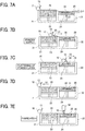
- FIGS. 7A, 7B, 7C, 7D, and 7E are diagrams of an operation flow in which the three-dimensional fabricating apparatus 601 fabricates a fabricated object according to an embodiment of the present disclosure.
- FIG. 7A illustrates a state in which the first fabrication layer 30 is formed on the fabrication table 24 of the fabrication chamber 22.
- the supply stage 23 of the supply chamber 21 is raised in a Z1 direction
- the fabrication table 24 of the fabrication chamber 22 is lowered in a Z2 direction.
- the lowering distance of the fabrication table 24 is set so that the interval between an upper surface of the fabrication chamber 22 (an upper surface of the powder layer) and a lower portion of the flattening roller 12 (a lower tangential portion) is ⁇ t1.
- the interval ⁇ t1 corresponds to the thickness of a powder layer 31 to be formed next.
- the interval ⁇ t1 is about several tens to 100 ⁇ m.
- the flattening roller 12 is moved in a Y2 direction (toward the fabrication chamber 22) while the flattening roller 12 is rotated in a forward direction (i.e., a direction indicated by arrow inside the flattening roller 12 in FIG. 7B ).
- a forward direction i.e., a direction indicated by arrow inside the flattening roller 12 in FIG. 7B .
- the flattening roller 12 is moved in parallel with the stage surface of the fabrication table 24 of the fabrication chamber 22 to form, as illustrated in FIG. 7D , the powder layer 31 having the predetermined thickness ⁇ t1 on the fabrication layer 30 of the fabrication table 24 (flattening). After the powder layer 31 is formed, the flattening roller 12 is moved in the Y1 direction and returned to the initial position as illustrated in FIG. 7D .
- the flattening roller 12 can move while maintaining a constant distance from the upper surface levels of the fabrication chamber 22 and the supply chamber 21.
- the flattening roller 12 that can move while maintaining the constant distance from the upper surface levels of the fabrication chamber 22 and the supply chamber 21 allows to form the powder layer 31 having a uniform thickness ⁇ t1 on the fabrication chamber 22 or on the fabrication layer 30 that has been already formed while conveying the powder 20 onto the fabrication chamber 22 by the flattening roller 12.
- the fabrication layer 30 for example, when the fabrication liquid 10 discharged from the heads 52 is mixed with the powder 20, adhesives contained in the powder 20 dissolve and bond together. Thus, particles of the powder 20 bind together to form the fabrication layer 30.
- the above-described step of forming the powder layer 31 by supplying and flattening the powder 20 and the above-described step of discharging fabrication liquid 10 by the heads 52 are repeated to form a new fabrication layer 30.
- the new fabrication layer 30 and the fabrication layer 30 thereunder are integrated to constitute a part of a three-dimensional fabricated object.
- the step of forming the powder layer 31 by supplying and flattening the powder 20 and the step of discharging the fabrication liquid with the heads 52 are repeated a required number of times to complete the fabrication of the three-dimensional fabrication object (fabricated object).
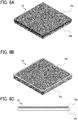
- FIGS. 8A, 8B, and 8C are views of the fabrication table 24 used in the three-dimensional fabricating apparatus 601 according to an embodiment of the present disclosure.
- FIG. 8A is a perspective view of the fabrication table 24 viewed from a placement surface on which the fabricated object is placed.
- the fabrication table 24 includes a supporter 24a having a plate shape of, for example, a quadrangular shape, which may be another shape such as a circular shape, a triangular shape, or a polygonal shape, and a separable portion 24b having a plate shape of a quadrangular shape substantially the same as the supporter 24a.
- the separable portion 24b is stacked on the supporter 24a.
- the supporter 24a is moved up and down in the Z directions illustrated in FIG. 4 by the motor 28.
- the separable portion 24b placed on the supporter 24a is also moved up and down together with the supporter 24a.
- the supporter 24a is formed of, for example, a rigid material, for example, metal such as steel.
- the separable portion 24b is formed of ceramics which is a heat resistant member.
- the separable portion 24b has a melting point higher than a melting point of the powder 20.
- the separable portion 24b can be separated from the supporter 24a and moved in a state in which a green body is placed on the separable portion 24b.
- the load of the fabricated object is entirely applied via the separable portion 24b to the supporter 24a positioned below the separable portion 24b.
- the supporter 24a is formed of a rigid material such as metal.
- the supporter 24a can sufficiently withstand the load of the fabricated object, and the separable portion 24b is not damaged.
- the separable portion 24b can be separated from the supporter 24a. Therefore, in a state in which the green body is placed on the separable portion 24b, the separable portion 24b can be separated from the supporter 24a and moved, and the process can proceed to the sintering step.
- FIG. 8A illustrates the example in which the supporter 24a and the separable portion 24b of the fabrication table 24 have the same shape.
- the fabrication table 24 is formed such that the size of the separable portion 24b is slightly smaller than the size of the supporter 24a and the separable portion 24b is accommodated in the supporter 24a.
- FIG. 8B is a perspective view of the fabrication table 24 according to the first variation in which the fabrication table 24 is viewed from the supporter 24a side.
- FIG. 8C is a cross-sectional view of the fabrication table 24 according to the first variation.
- the supporter 24a has a bottomed box shape, and the separable portion 24b is accommodated in the supporter 24a.
- the supporter 24a is formed of, for example, a rigid material such as steel (metallic material or the like), and the separable portion 24b is formed of ceramics which is a heat-resistant member.
- the separable portion 24b can be separated from the supporter 24a and moved in a state in which a green body is placed on the separable portion 24b.
- the load of the fabricated object is also entirely applied via the separable portion 24b to the supporter 24a positioned below the separable portion 24b.
- the supporter 24a is formed of a rigid material such as metal.
- the supporter 24a can sufficiently withstand the load of the fabricated object, and the separable portion 24b is not damaged.
- the separable portion 24b can be separated from the supporter 24a. Therefore, in a state in which the green body is placed on the separable portion 24b, the separable portion 24b can be separated from the supporter 24a and moved, and the process can proceed to the sintering step.
- the bottom surface and the side surface of the separable portion 24b are substantially in contact with the supporter 24a.
- the outer peripherals of the fabrication table 24 are in contact with the walls of the fabrication chamber 22 during fabricating to prevent the powder 20 from passing through.
- the above-described configuration according to the first variation can prevent the separable portion 24b from being damaged.
- the behavior of the powder 20 at the time of powder layering is different in the vicinity of the wall surfaces of the fabrication chamber 22 (for example, an area of approximately 1 mm to 5 mm from the wall surface) from a center portion of the fabrication chamber 22 and the fabricated object is not normally disposed in the vicinity of the wall surfaces of the fabrication chamber 22. Accordingly, there is no disadvantage due to the above-described configuration according to the first variation.
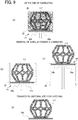
- Parts (a), (b), (c), and (d) of FIG. 9 are illustrations of an operational flow in which a fabricated green body is transferred to the sintering step according to an embodiment of the present disclosure.
- Parts (a), (b), (c), and (d) of FIG. 9 illustrate an example in which the fabrication table 24 according to the first variation described with reference to FIGS. 8B and 8C is provided as the fabrication table 24.
- Part (a) of FIG. 9 is a cross-sectional view of the fabrication chamber 22 in which the inside of the fabrication chamber 22 at the end of fabricating of a fabricated object is transparently illustrated.
- Part (b) of FIG. 9 is a cross-sectional view of the fabrication chamber 22 in which the inside of the fabrication chamber 22 after the removal of the surplus powder is transparently illustrated.
- Part (c) of FIG. 9 is a cross-sectional view of the separable portion 24b from which the surplus powder has been removed and on which a three-dimensional object is placed immediately before the transition to the sintering step.
- Part (d) of FIG. 9 is a cross-sectional view of the separable portion 24b separated from the supporter 24a and transferred to the sintering step.
- the fabrication table 24 includes the supporter 24a and the separable portion 24b.
- the separable portion 24b is separable from the supporter 24a.
- the separable portion 24b is fixed to the supporter 24a.
- the separable portion 24b can be taken out to the outside of the three-dimensional fabricating apparatus 601 or the outside of the fabrication chamber 22 after the end of fabricating.
- the supporter 24a is formed of metal such as aluminum, steel, or stainless steel.
- the separable portion 24b is formed of ceramic such as alumina, magnesia, or zirconia.
- the steps from the end of fabrication of the fabricated object illustrated in part (a) of FIG. 9 to the removal of the unsolidified powder material illustrated in part (b) of FIG. 9 are performed in the fabrication chamber 22. Subsequently, when the process proceeds to the sintering step, as illustrated in part (c) and (d) of FIG. 9 , a fabricated object 117 is transferred together with the separable portion 24b and is sintered.
- the separable portion 24b on which the fabricated object (green body) 117 is placed can be transferred from the three-dimensional fabricating apparatus 601 or the fabrication chamber 22 to the sintering step by a robot arm, a belt conveyor, or the like. Therefore, the process from the fabricating step to the sintering step of the fabricated object 117 can be automated.
- the same effect as described above can be obtained by using a material that is sintered under different conditions from the powder 20 and has a melting point higher than the sintering temperature of the powder material.
- the powder 20 may be sintered or fired using a material other than metal.
- the unsolidified powder can be efficiently removed by making the separable portion 24b of a material resistant to the removing liquid.
- FIGS. 10A, 10B, 10C, and 10D are perspective views of a fabrication table 24 according to a second variation of the present disclosure.
- FIG. 10A is a perspective view of the fabrication table 24 according to the second variation as viewed from a placement surface side (upper surface side) of a fabricated object.
- FIG. 10B is a perspective view of the fabrication table 24 according to the second variation as viewed from a side (bottom surface side) opposite to the placement surface side (upper surface side) on which the fabricated object is placed.
- FIG. 10C is a perspective view of the fabrication table 24 in a state in which a second separable portion 24c provided in the fabrication table 24 according to the second variation is removed, as viewed from the placement surface side (upper surface side) of the fabricated object.
- FIG. 10A is a perspective view of the fabrication table 24 according to the second variation as viewed from a placement surface side (upper surface side) of a fabricated object.
- FIG. 10B is a perspective view of the fabrication table 24 according to
- 10D is a perspective view of the fabrication table 24 in a state in which the second separable portion 24c provided in the fabrication table 24 according to the second variation is removed, as viewed from the side (bottom surface side) opposite to the placement surface side (upper surface side) on which the fabricated object is placed.
- the fabrication table 24 according to the second variation includes the second separable portion 24c (as an example of a separable portion for partial exposing) in addition to the supporter 24a and the separable portion 24b (or the first separable portion 24b) described above.
- the supporter 24a and the second separable portion 24c are formed, for example, of the same material such as metals.
- the first separable portion 24b can be gripped by a robot arm or the like.
- the transfer of the fabricated object 117 to the sintering step can be facilitated.
- automation from the fabricating step to the sintering step of the fabricated object 117 can be more easily realized.
- the three-dimensional fabricating apparatus 601 includes the fabrication table 24 including the supporter 24a formed of a rigid material and the separable portion 24b formed of a heat-resistant material. After the completion of the fabricating, the separable portion 24b on which the fabricated object is placed is separated from the supporter 24a by, for example, a robot arm or the like and transferred, and the process proceeds to the sintering step. Thus, automating the process from the fabricating step to the sintering step can be realized.
- the fabricated object after completion of fabricating is not directly gripped and transferred by a robot arm or the like.
- the separable portion 24b on which the fabricated object after completion of fabricating is placed is gripped and transferred. Therefore, even a fabricated object (green body) having a delicate structure can be transferred to the sintering step without being damaged.
Landscapes
- Chemical & Material Sciences (AREA)
- Engineering & Computer Science (AREA)
- Materials Engineering (AREA)
- Manufacturing & Machinery (AREA)
- Physics & Mathematics (AREA)
- Mechanical Engineering (AREA)
- Optics & Photonics (AREA)
- Thermal Sciences (AREA)
- Powder Metallurgy (AREA)
Abstract
Description
- The present disclosure relates to a fabrication table and a fabricating apparatus.
- There is known a binder jetting (BJ) fabricating apparatus that repeats a step of forming a powder material into layers based on three-dimensional data and a step of solidifying the formed layered powder material into a cross-sectional shape of the three-dimensional data to fabricate a three-dimensional object. The fabricated object formed by the BJ method is sintered after unsolidified powder is removed. Thus, a metal fabricated object is fabricated.
- In the configuration disclosed in Japanese Unexamined Patent Application Publication No.
2012-224906 - In metal fabrication by the BJ method, when a fabricated object (green body) is sintered after removal of surplus powder, the fabricated object (green body) needs to be placed on a ceramic setter.
- However, the strength of the fabricated object is low in a state in which the fabricated object is the green body. Thus, holding and moving the green body by a robot arm or the like is difficult. Therefore, automating the fabrication process from a fabricating step to a sintering step has been difficult.
- The technology described in Japanese Unexamined Patent Application Publication No.
2012-224906 2012-224906 2012-224906 - In light of the above-described disadvantage, a purpose of the present disclosure is to provide a fabrication table and a three-dimensional fabricating apparatus in which a process from a fabricating step to a sintering step is automated.
- In an aspect of the present disclosure, a fabrication table includes a separable portion and a supporter. The separable portion is formed of a heat-resistant member on which a three-dimensional fabricated object is to be placed. The supporter is formed of a rigid material and configured to support the separable portion.
- In another aspect of the present disclosure, a fabricating apparatus includes a fabricating device and the fabrication table. The fabricating device is configured to fabricate and sinter a three-dimensional fabricated object.
- A more complete appreciation of the disclosure and many of the attendant advantages thereof will be readily obtained as the same becomes better understood by reference to the following detailed description when considered in connection with the accompanying drawings, wherein:
-
FIG. 1 is a top view of a three-dimensional fabricating apparatus according to an embodiment of the present disclosure; -
FIG. 2 is a side view of a three-dimensional fabricating apparatus illustrated as being partially cut away, according to an embodiment of the present disclosure; -
FIG. 3 is a cross-sectional view of a powder chamber of a three-dimensional fabricating apparatus according to an embodiment of the present disclosure; -
FIG. 4 is a perspective view of a main part of a three-dimensional fabricating apparatus according to an embodiment of the present disclosure; -
FIG. 5 is a perspective view of a powder chamber and a liquid discharge unit of a three-dimensional fabricating apparatus according to an embodiment of the present disclosure; -
FIG. 6 is a block diagram of a hardware configuration of a three-dimensional fabricating apparatus according to an embodiment of the present disclosure; -
FIGS. 7A, 7B, 7C, 7D, and 7E are illustrations of an operation flow in which a three-dimensional fabricating apparatus fabricates a fabricated object according to an embodiment of the present disclosure; -
FIG. 8A is a perspective view of a fabrication table of a three-dimensional fabricating apparatus according to an embodiment of the present disclosure; -
FIG. 8B is a view of a fabrication table of a three-dimensional fabricating apparatus according to a first variation of the present disclosure; -
FIG. 8C is a cross-sectional side view of the fabrication table ofFIG. 8B ; -
FIG. 9 is an illustration of an operational flow in which a fabricated green body is transferred to a sintering step according to an embodiment of the present disclosure; and -
FIGS. 10A, 10B, 10C, and 10D are perspective views of a fabrication table according to a second variation of the present disclosure. - The accompanying drawings are intended to depict embodiments of the present disclosure and should not be interpreted to limit the scope thereof. The accompanying drawings are not to be considered as drawn to scale unless explicitly noted.
- In describing embodiments illustrated in the drawings, specific terminology is employed for the sake of clarity. However, the disclosure of this patent specification is not intended to be limited to the specific terminology so selected and it is to be understood that each specific element includes all technical equivalents that operate in a similar manner and achieve similar results.
- Although the embodiments are described with technical limitations with reference to the attached drawings, such description is not intended to limit the scope of the disclosure and all of the components or elements described in the embodiments of this disclosure are not necessarily indispensable.
- Referring now to the drawings, embodiments of the present disclosure are described below. In the drawings for explaining the following embodiments, the same reference codes are allocated to elements (members or components) having the same function or shape and redundant descriptions thereof are omitted below.
- A three-dimensional fabricating apparatus (also referred to as a powder fabricating apparatus or a powder fabricating apparatus) 601 according to an embodiments of the present disclosure includes a fabricating
device 1 and a fabricatingunit 5. The fabricatingdevice 1 forms afabrication layer 30, which is a layered three-dimensional object formed by binding powder (powder). The fabricatingunit 5 discharges afabrication liquid 10 onto apowder layer 31 spread in a layered manner in the fabricatingdevice 1 to fabricate a three-dimensional object. - The fabricating
device 1 includes apowder chamber 11 and aflattening roller 12 as a rotator which is a flattening member (recoater). Theflattening roller 12 may be, for example, a plate (blade) in place of a rotator. - The
powder chamber 11 includes asupply chamber 21 to supply apowder 20 and afabrication chamber 22 in which thefabrication layer 30 is laminated and a three-dimensional object is fabricated. A bottom of thesupply chamber 21 is movable in a vertical direction (height direction) as asupply stage 23. Similarly, a bottom of thefabrication chamber 22 is movable in the vertical direction (height direction) as a fabrication table 24. A three-dimensional object in which thefabrication layer 30 is laminated is fabricated on the fabrication table 24. - For example, as illustrated in
FIG. 4 , thesupply stage 23 is moved up and down in directions indicated by arrow Z (height direction) by amotor 27 and the fabrication table 24 is also moved up and down in the directions indicated by arrow Z direction by amotor 28. Hereinafter, the directions indicated by arrow Z simply referred to as "Z directions". - The
powder chamber 11 has a box shape, and includes two chambers, i.e., thesupply chamber 21 and thefabrication chamber 22, each having an open upper surface. Thesupply stage 23 is disposed inside thesupply chamber 21 and the fabrication table 24 is disposed inside thefabrication chamber 22 so as to be movable up and down. - Side faces of the
supply stage 23 are disposed so as to be in contact with inner side faces of thesupply chamber 21. Side faces of the fabrication table 24 are disposed so as to be in contact with inner side faces of thefabrication chamber 22. The upper surfaces of thesupply stage 23 and the fabrication table 24 are kept horizontal. - As illustrated in
FIG. 5 , a surpluspowder receiving chamber 29 including the peripheries of thesupply chamber 21 and thefabrication chamber 22 is provided adjacent to thefabrication chamber 22. Thepowder 20 is transferred and supplied with the flatteningroller 12 when thepowder layer 31 is formed, and a surplus of thepowder 20 falls to the surpluspowder receiving chamber 29. A powder supply device 554 (seeFIG. 6 ) is provided above thesupply chamber 21, and thesurplus powder 20 that has fallen into the surpluspowder receiving chamber 29 is returned to thesupply chamber 21 by thepowder supply device 554. - During an initial operation of fabricating or when the amount of powder in the
supply chamber 21 decreases, thepowder 20 in a tank of thepowder supply device 554 is supplied to thesupply chamber 21. Examples of a method of a conveyance of thepowder 20 for powder supply include a screw conveyor method using a screw, an air conveyance method using air, or the like. - The flattening
roller 12 supplies thepowder 20, which has been supplied onto thesupply stage 23 of thesupply chamber 21 to thefabrication chamber 22 and flattens thepowder 20 to form thepowder layer 31. The flatteningroller 12 is moved by areciprocating mechanism 25 so as to be reciprocated in directions indicated by arrow Y direction ((hereinafter, Y directions) illustrated inFIGS. 2 and4 ) along a stage surface (surface on which thepowder 20 is placed) of the fabrication table 24 relatively to the stage surface. The flatteningroller 12 is rotationally driven by amotor 26. - The flattening
roller 12 transfers and supplies thepowder 20 from thesupply chamber 21 to thefabrication chamber 22, and flattens the surface of thepowder 20 to form thepowder layer 31 which is a layered powder having a predetermined thickness. The flatteningroller 12 is a rod-shaped member longer than the inner dimensions (the width of the portion to which the powder is supplied or charged) of each of thefabrication chamber 22 and thesupply chamber 21, and is reciprocated in the Y directions (in other words, along a sub-scanning direction) along the stage surface by thereciprocating mechanism 25. - The flattening
roller 12 is rotationally driven by themotor 26 illustrated inFIG. 4 and horizontally moves to pass above thesupply chamber 21 and thefabrication chamber 22 from the outside of thesupply chamber 21. Thus, thepowder 20 is transferred and supplied onto thefabrication chamber 22, and the flatteningroller 12 flattens thepowder 20 while passing over thefabrication chamber 22 to form thepowder layer 31. - As illustrated in
FIG. 2 , the flatteningroller 12 is provided with apowder removing plate 13. Thepowder removing plate 13 moves together with the flatteningroller 12 in a state of being in contact with a peripheral surface of the flatteningroller 12, and removes thepowder 20 adhering to the flatteningroller 12. - The three-dimensional fabricating
apparatus 601 according to the present embodiment is described on the assumption that thepowder chamber 11 of the fabricatingdevice 1 includes two chambers, i.e., thesupply chamber 21 and thefabrication chamber 22. However, only thefabrication chamber 22 may be provided, and thepowder 20 may be supplied from a powder supply device to thefabrication chamber 22 and flattened by the flatteningroller 12. - The fabricating
unit 5 includes aliquid discharge unit 50 that discharges thefabrication liquid 10 onto thepowder layer 31 on the fabrication table 24. The fabricatingunit 5 includes aslider 72 movably held by aguide 71 disposed on abase 7, and the entire fabricatingunit 5 can reciprocate in the Y directions (in other words, along the sub-scanning direction) orthogonal to directions indicated by arrow X (hereinafter, X directions) inFIG. 4 . The entire fabricatingunit 5 is reciprocated in the Y direction by a Y-direction scanning mechanism 552 (illustrated inFIG. 6 ) described later. - The
liquid discharge unit 50 includes acarriage 51 and, for example, two liquid discharge heads (hereinafter simply referred to as "heads") 52a and 52b provided on thecarriage 51. Note that the number of heads is not limited to two and may be one or three or more. Theliquid discharge unit 50 is provided to be movable up and down in the Z directions illustrated inFIG. 4 together withguides FIG. 6 ) described later. - The
carriage 51 is movably held by theguide 54 and theguide 55. Theguide 54 and theguide 55 are held byside plates 70 on both sides of the fabricatingunit 5 so as to be raised and lowered. Thecarriage 51 is reciprocated by an X-direction scanning mechanism 550 (illustrated inFIG. 6 ), which will be described later, via a main scanning movement mechanism including a motor, a pulley, and a belt, in the X directions that are the main scanning directions. Thecarriage 51 is provided with a powder post-supply unit that supplies thepowder 20 to at least a region to which thefabrication liquid 10 adheres when onefabrication layer 30 is formed in thefabrication chamber 22. - In each of the two
heads fabrication liquid 10 are arranged. The head configuration and the liquid to be discharged are not limited to the above-described configuration. A plurality oftanks 60 containing the above-described liquids are mounted on atank mounter 56. The liquid in eachtank 60 is supplied to thehead - A
maintenance mechanism 61 that performs maintenance and recovery of theheads 52 of theliquid discharge unit 50 is provided on one side in the X direction. Themaintenance mechanism 61 includescaps 62 and awiper 63. Themaintenance mechanism 61 brings thecaps 62 into close contact with the nozzle surfaces (the surface on which the nozzles are formed) of theheads 52 and sucks the fabricating liquid from the nozzles. Thus, the powder clogged in the nozzles and the fabricating liquid having a high viscosity can be discharged. Thereafter, the nozzle surfaces of theheads 52 are wiped by thewiper 63 to form meniscuses of the nozzles in a state in which the inside of the nozzles is in a negative pressure state. When thefabrication liquid 10 is not discharged, themaintenance mechanism 61 covers the nozzle surfaces of theheads 52 with thecaps 62 to prevent mixing of thepowder 20 into the nozzles and drying of thefabrication liquid 10. -
FIG. 6 is a block diagram of a hardware configuration of the three-dimensional fabricatingapparatus 601 according to an embodiment of the present disclosure. InFIG. 6 , acontroller 500 of the three-dimensional fabricatingapparatus 601 includes a central processing unit (CPU) 501, a read only memory (ROM) 502, a random access memory (RAM) 503, and a non-volatile random access memory (NVRAM) 504. TheCPU 501 controls the entire three-dimensional fabricatingapparatus 601. TheROM 502 stores not only various programs such as a fabrication program for causing theCPU 501 to execute three-dimensional fabrication control but also fixed data and the like. TheRAM 503 temporarily stores fabrication data and the like. TheNVRAM 504 is a non-volatile memory that retains data while the device is powered off. TheCPU 501, theROM 502, and the RAM503 mainly form amain controller 500A. - The
controller 500 includes an application specific integrated circuit (ASIC) 505 that processes input and output signals for controlling the entire three-dimensional fabricatingapparatus 601 in addition to various signal processing performed on image data. Thecontroller 500 includes an external interface (external I/F) 506 for transmitting and receiving fabrication data and the like to and from a fabricationdata generation apparatus 600, which is an external device. - The fabrication
data generation apparatus 600 is an apparatus that generates fabrication data obtained by slicing a fabricated object in a final form into fabrication layers, and includes an information processing apparatus such as a personal computer. - Further, the
controller 500 includes an input and output unit (I/O) 507 for capturing detection signals of various sensors, and a headdrive control unit 508 that controls driving of each of theheads 52 of theliquid discharge unit 50. - The
controller 500 includes amotor driver 510 that drives a motor of theX-direction scanning mechanism 550 to move thecarriage 51 of theliquid discharge unit 50 in the X directions (i.e. the main scanning directions), and amotor driver 512 that drives a motor of the Y-direction scanning mechanism 552 to move the fabricatingunit 5 in the Y directions (or along the sub-scanning direction). - In addition, the
controller 500 includes amotor driving unit 511 that drives a motor of a Zdirection lifting mechanism 551 to move (i.e. lift up and down) thecarriage 51 of theliquid discharge unit 50 in the Z directions. The elevation in the Z directions may elevate the entire fabricatingunit 5. - The
controller 500 includes amotor driver 513 that drives themotor 27 to vertically move thesupply stage 23, and amotor driver 514 that drives themotor 28 to vertically move the fabrication table 24. Thecontroller 500 includes amotor driver 515 that drives themotor 553 of thereciprocating mechanism 25 for moving the flatteningroller 12, and amotor driver 516 that drives themotor 26 for rotationally driving the flatteningroller 12. - Further, the
controller 500 includes a supply system driver 517 that drives thepowder supply device 554 to supply thepowder 20 to thesupply chamber 21, and amaintenance driver 518 that drives themaintenance mechanism 61 of theliquid discharge unit 50. - The I/
O 507 of thecontroller 500 is supplied with detection signals indicating temperature and moisture as environmental conditions of the three-dimensional fabricatingapparatus 601, which are detected by a temperature andmoisture sensor 560, and is also supplied with detection signals of other sensors. Anoperation panel 522 for inputting and displaying information necessary for the three-dimensional fabricatingapparatus 601 is connected to thecontroller 500. - Note that a three-dimensional fabricating system includes the fabrication
data generation apparatus 600 and the three-dimensional fabricatingapparatus 601. -
FIGS. 7A, 7B, 7C, 7D, and 7E are diagrams of an operation flow in which the three-dimensional fabricatingapparatus 601 fabricates a fabricated object according to an embodiment of the present disclosure.FIG. 7A illustrates a state in which thefirst fabrication layer 30 is formed on the fabrication table 24 of thefabrication chamber 22. When thenext fabrication layer 30 is formed on thefabrication layer 30, as illustrated inFIG. 7A , thesupply stage 23 of thesupply chamber 21 is raised in a Z1 direction, and the fabrication table 24 of thefabrication chamber 22 is lowered in a Z2 direction. At this time, the lowering distance of the fabrication table 24 is set so that the interval between an upper surface of the fabrication chamber 22 (an upper surface of the powder layer) and a lower portion of the flattening roller 12 (a lower tangential portion) is Δt1. The interval Δt1 corresponds to the thickness of apowder layer 31 to be formed next. As an example, the interval Δt1 is about several tens to 100 µm. - Subsequently, as illustrated in
FIG. 7B , the flatteningroller 12 is moved in a Y2 direction (toward the fabrication chamber 22) while the flatteningroller 12 is rotated in a forward direction (i.e., a direction indicated by arrow inside the flatteningroller 12 inFIG. 7B ). Thus, thepowder 20 located above the upper surface level of thesupply chamber 21 is transferred and supplied to the fabrication chamber 22 (powder supply). - Furthermore, as illustrated in
FIG. 7C , the flatteningroller 12 is moved in parallel with the stage surface of the fabrication table 24 of thefabrication chamber 22 to form, as illustrated inFIG. 7D , thepowder layer 31 having the predetermined thickness Δt1 on thefabrication layer 30 of the fabrication table 24 (flattening). After thepowder layer 31 is formed, the flatteningroller 12 is moved in the Y1 direction and returned to the initial position as illustrated inFIG. 7D . - In the present embodiment, the flattening
roller 12 can move while maintaining a constant distance from the upper surface levels of thefabrication chamber 22 and thesupply chamber 21. The flatteningroller 12 that can move while maintaining the constant distance from the upper surface levels of thefabrication chamber 22 and thesupply chamber 21 allows to form thepowder layer 31 having a uniform thickness Δt1 on thefabrication chamber 22 or on thefabrication layer 30 that has been already formed while conveying thepowder 20 onto thefabrication chamber 22 by the flatteningroller 12. - Then, as illustrated in
FIG. 7E , droplets offabrication liquid 10 are discharged from theheads 52 of theliquid discharge unit 50 to form and laminate thefabrication layer 30 on the next powder layer 31 (fabrication). - Note that, for the
fabrication layer 30, for example, when thefabrication liquid 10 discharged from theheads 52 is mixed with thepowder 20, adhesives contained in thepowder 20 dissolve and bond together. Thus, particles of thepowder 20 bind together to form thefabrication layer 30. - Subsequently, the above-described step of forming the
powder layer 31 by supplying and flattening thepowder 20 and the above-described step of dischargingfabrication liquid 10 by theheads 52 are repeated to form anew fabrication layer 30. At this time, thenew fabrication layer 30 and thefabrication layer 30 thereunder are integrated to constitute a part of a three-dimensional fabricated object. - Then, the step of forming the
powder layer 31 by supplying and flattening thepowder 20 and the step of discharging the fabrication liquid with theheads 52 are repeated a required number of times to complete the fabrication of the three-dimensional fabrication object (fabricated object). -
FIGS. 8A, 8B, and 8C are views of the fabrication table 24 used in the three-dimensional fabricatingapparatus 601 according to an embodiment of the present disclosure.FIG. 8A is a perspective view of the fabrication table 24 viewed from a placement surface on which the fabricated object is placed. As illustrated inFIG. 8A , the fabrication table 24 includes asupporter 24a having a plate shape of, for example, a quadrangular shape, which may be another shape such as a circular shape, a triangular shape, or a polygonal shape, and aseparable portion 24b having a plate shape of a quadrangular shape substantially the same as thesupporter 24a. Theseparable portion 24b is stacked on thesupporter 24a. - As described above, the
supporter 24a is moved up and down in the Z directions illustrated inFIG. 4 by themotor 28. Theseparable portion 24b placed on thesupporter 24a is also moved up and down together with thesupporter 24a. Thesupporter 24a is formed of, for example, a rigid material, for example, metal such as steel. On the other hand, theseparable portion 24b is formed of ceramics which is a heat resistant member. Theseparable portion 24b has a melting point higher than a melting point of thepowder 20. Theseparable portion 24b can be separated from thesupporter 24a and moved in a state in which a green body is placed on theseparable portion 24b. - In the case of the above-described fabrication table 24, the load of the fabricated object is entirely applied via the
separable portion 24b to thesupporter 24a positioned below theseparable portion 24b. Thesupporter 24a is formed of a rigid material such as metal. Thus, thesupporter 24a can sufficiently withstand the load of the fabricated object, and theseparable portion 24b is not damaged. Theseparable portion 24b can be separated from thesupporter 24a. Therefore, in a state in which the green body is placed on theseparable portion 24b, theseparable portion 24b can be separated from thesupporter 24a and moved, and the process can proceed to the sintering step. -
FIG. 8A illustrates the example in which thesupporter 24a and theseparable portion 24b of the fabrication table 24 have the same shape. However, in examples illustrated inFIGS. 8B and 8C , the fabrication table 24 is formed such that the size of theseparable portion 24b is slightly smaller than the size of thesupporter 24a and theseparable portion 24b is accommodated in thesupporter 24a. - That is,
FIG. 8B is a perspective view of the fabrication table 24 according to the first variation in which the fabrication table 24 is viewed from thesupporter 24a side.FIG. 8C is a cross-sectional view of the fabrication table 24 according to the first variation. As apparent fromFIGS. 8B and 8C , in the fabrication table 24 according to the first variation, thesupporter 24a has a bottomed box shape, and theseparable portion 24b is accommodated in thesupporter 24a. - The
supporter 24a is formed of, for example, a rigid material such as steel (metallic material or the like), and theseparable portion 24b is formed of ceramics which is a heat-resistant member. Theseparable portion 24b can be separated from thesupporter 24a and moved in a state in which a green body is placed on theseparable portion 24b. - In the fabrication table 24 according to the first variation, the load of the fabricated object is also entirely applied via the
separable portion 24b to thesupporter 24a positioned below theseparable portion 24b. Thesupporter 24a is formed of a rigid material such as metal. Thus, thesupporter 24a can sufficiently withstand the load of the fabricated object, and theseparable portion 24b is not damaged. In addition, theseparable portion 24b can be separated from thesupporter 24a. Therefore, in a state in which the green body is placed on theseparable portion 24b, theseparable portion 24b can be separated from thesupporter 24a and moved, and the process can proceed to the sintering step. - In the case of the first variation, the bottom surface and the side surface of the
separable portion 24b are substantially in contact with thesupporter 24a. The outer peripherals of the fabrication table 24 are in contact with the walls of thefabrication chamber 22 during fabricating to prevent thepowder 20 from passing through. However, the above-described configuration according to the first variation can prevent theseparable portion 24b from being damaged. The behavior of thepowder 20 at the time of powder layering is different in the vicinity of the wall surfaces of the fabrication chamber 22 (for example, an area of approximately 1 mm to 5 mm from the wall surface) from a center portion of thefabrication chamber 22 and the fabricated object is not normally disposed in the vicinity of the wall surfaces of thefabrication chamber 22. Accordingly, there is no disadvantage due to the above-described configuration according to the first variation. - Parts (a), (b), (c), and (d) of
FIG. 9 are illustrations of an operational flow in which a fabricated green body is transferred to the sintering step according to an embodiment of the present disclosure. Parts (a), (b), (c), and (d) ofFIG. 9 illustrate an example in which the fabrication table 24 according to the first variation described with reference toFIGS. 8B and 8C is provided as the fabrication table 24. - Part (a) of
FIG. 9 is a cross-sectional view of thefabrication chamber 22 in which the inside of thefabrication chamber 22 at the end of fabricating of a fabricated object is transparently illustrated. Part (b) ofFIG. 9 is a cross-sectional view of thefabrication chamber 22 in which the inside of thefabrication chamber 22 after the removal of the surplus powder is transparently illustrated. Part (c) ofFIG. 9 is a cross-sectional view of theseparable portion 24b from which the surplus powder has been removed and on which a three-dimensional object is placed immediately before the transition to the sintering step. Part (d) ofFIG. 9 is a cross-sectional view of theseparable portion 24b separated from thesupporter 24a and transferred to the sintering step. - As described with reference to
FIGS. 8B and 8C , the fabrication table 24 includes thesupporter 24a and theseparable portion 24b. Theseparable portion 24b is separable from thesupporter 24a. During fabricating, theseparable portion 24b is fixed to thesupporter 24a. However, theseparable portion 24b can be taken out to the outside of the three-dimensional fabricatingapparatus 601 or the outside of thefabrication chamber 22 after the end of fabricating. - The
supporter 24a is formed of metal such as aluminum, steel, or stainless steel. Theseparable portion 24b is formed of ceramic such as alumina, magnesia, or zirconia. - The steps from the end of fabrication of the fabricated object illustrated in part (a) of
FIG. 9 to the removal of the unsolidified powder material illustrated in part (b) ofFIG. 9 are performed in thefabrication chamber 22. Subsequently, when the process proceeds to the sintering step, as illustrated in part (c) and (d) ofFIG. 9 , a fabricatedobject 117 is transferred together with theseparable portion 24b and is sintered. - Even when the fabricated object (green body) 117 has a weak strength due to, for example, a fine shape or the like, the
separable portion 24b on which the fabricated object (green body) 117 is placed can be transferred from the three-dimensional fabricatingapparatus 601 or thefabrication chamber 22 to the sintering step by a robot arm, a belt conveyor, or the like. Therefore, the process from the fabricating step to the sintering step of the fabricatedobject 117 can be automated. - Note that even if the material of the
separable portion 24b is other than ceramics, the same effect as described above can be obtained by using a material that is sintered under different conditions from thepowder 20 and has a melting point higher than the sintering temperature of the powder material. Thepowder 20 may be sintered or fired using a material other than metal. - Further, in the case of using a method of immersing the unsolidified powder in a liquid (removing liquid) such as water or a solvent when removing the unsolidified powder, the unsolidified powder can be efficiently removed by making the
separable portion 24b of a material resistant to the removing liquid. -
FIGS. 10A, 10B, 10C, and 10D are perspective views of a fabrication table 24 according to a second variation of the present disclosure.FIG. 10A is a perspective view of the fabrication table 24 according to the second variation as viewed from a placement surface side (upper surface side) of a fabricated object.FIG. 10B is a perspective view of the fabrication table 24 according to the second variation as viewed from a side (bottom surface side) opposite to the placement surface side (upper surface side) on which the fabricated object is placed.FIG. 10C is a perspective view of the fabrication table 24 in a state in which a secondseparable portion 24c provided in the fabrication table 24 according to the second variation is removed, as viewed from the placement surface side (upper surface side) of the fabricated object.FIG. 10D is a perspective view of the fabrication table 24 in a state in which the secondseparable portion 24c provided in the fabrication table 24 according to the second variation is removed, as viewed from the side (bottom surface side) opposite to the placement surface side (upper surface side) on which the fabricated object is placed. - The fabrication table 24 according to the second variation includes the second
separable portion 24c (as an example of a separable portion for partial exposing) in addition to thesupporter 24a and theseparable portion 24b (or the firstseparable portion 24b) described above. Thesupporter 24a and the secondseparable portion 24c are formed, for example, of the same material such as metals. When the secondseparable portion 24c is removed from the fabrication table 24, as illustrated inFIG. 10D , a portion of the firstseparable portion 24b is exposed. - With such a configuration, when a fabricated object 117 (green body) after the completion of fabrication is taken out of the three-dimensional fabricating
apparatus 601 or thefabrication chamber 22, the firstseparable portion 24b can be gripped by a robot arm or the like. Thus, the transfer of the fabricatedobject 117 to the sintering step can be facilitated. As a result, automation from the fabricating step to the sintering step of the fabricatedobject 117 can be more easily realized. - As apparent from the above descriptions, the three-dimensional fabricating
apparatus 601 according to embodiments of the present disclosure includes the fabrication table 24 including thesupporter 24a formed of a rigid material and theseparable portion 24b formed of a heat-resistant material. After the completion of the fabricating, theseparable portion 24b on which the fabricated object is placed is separated from thesupporter 24a by, for example, a robot arm or the like and transferred, and the process proceeds to the sintering step. Thus, automating the process from the fabricating step to the sintering step can be realized. - In addition, the fabricated object after completion of fabricating is not directly gripped and transferred by a robot arm or the like. However, the
separable portion 24b on which the fabricated object after completion of fabricating is placed is gripped and transferred. Therefore, even a fabricated object (green body) having a delicate structure can be transferred to the sintering step without being damaged. - The above-described embodiments are presented as examples and are not intended to limit the scope of the present disclosure. The above-described embodiments can be implemented in other various forms, and various omissions, replacements, and changes can be made without departing from the scope of the disclosure. In addition, the embodiments and modifications or variations thereof are included in the scope and the gist of the disclosure.
Claims (8)
- A fabrication table (24) comprising:a separable portion (24b) formed of a heat-resistant member on which a three-dimensional fabricated object is to be placed; anda supporter (24a) formed of a rigid material and configured to support the separable portion (24b).
- The fabrication table (24) according to claim 1,
wherein the supporter (24a) has a bottomed box shape, and
wherein the separable portion (24b) is detachably accommodated in the supporter (24a) having the bottomed box shape. - The fabrication table (24) according to claim 2,
wherein the separable portion (24b) is accommodated in the supporter (24a) having the bottomed box shape in a state of being in contact with the supporter without a gap. - The fabrication table (24) according to any one of claims 2 to 3,
wherein the supporter (24a) having the bottomed box shape includes another separable portion (24c) separable from the supporter (24a), and
wherein said another separable portion (24c) is configured to expose a part of the separable portion (24b) accommodated in the supporter (24a). - The fabrication table (24) according to any one of claims 1 to 4,
wherein the separable portion (24b) has a melting point higher than a melting point of powder (20) for fabricating the three-dimensional fabricated object. - The fabrication table (24) according to any one of claims 1 to 5,
wherein the supporter (24a) is formed of metal, and
wherein the separable portion (24b) is formed of a ceramic member. - The fabrication table (24) according to any one of claims 1 to 6,
wherein the separable portion (24b) has a plate shape. - A fabricating apparatus (601) comprising:a fabricating device (1) configured to fabricate and sinter a three-dimensional fabricated object; andthe fabrication table (24) according to any one of claims 1 to 7.
Applications Claiming Priority (1)
| Application Number | Priority Date | Filing Date | Title |
|---|---|---|---|
| JP2020064446A JP2021161492A (en) | 2020-03-31 | 2020-03-31 | Molding table and molding apparatus |
Publications (1)
| Publication Number | Publication Date |
|---|---|
| EP3888823A1 true EP3888823A1 (en) | 2021-10-06 |
Family
ID=75252544
Family Applications (1)
| Application Number | Title | Priority Date | Filing Date |
|---|---|---|---|
| EP21165447.0A Withdrawn EP3888823A1 (en) | 2020-03-31 | 2021-03-29 | Fabrication table and fabricating apparatus |
Country Status (4)
| Country | Link |
|---|---|
| US (1) | US11794416B2 (en) |
| EP (1) | EP3888823A1 (en) |
| JP (1) | JP2021161492A (en) |
| CN (1) | CN113458420A (en) |
Families Citing this family (1)
| Publication number | Priority date | Publication date | Assignee | Title |
|---|---|---|---|---|
| EP4234134B1 (en) | 2022-02-25 | 2025-04-02 | Ricoh Company, Ltd. | Method of fabricating three-dimensional object and apparatus for fabricating three-dimensional object |
Citations (5)
| Publication number | Priority date | Publication date | Assignee | Title |
|---|---|---|---|---|
| EP0734842A1 (en) * | 1995-03-30 | 1996-10-02 | EOS GmbH ELECTRO OPTICAL SYSTEMS | Apparatus and method for manufacturing three-dimensional objects |
| US20040018107A1 (en) * | 2002-07-23 | 2004-01-29 | Behrokh Khoshnevis | Metallic parts fabrication using selective inhibition of sintering (SIS) |
| JP2012224906A (en) | 2011-04-19 | 2012-11-15 | Panasonic Corp | Method for manufacturing three-dimensionally shaped article |
| US9937702B1 (en) * | 2014-01-20 | 2018-04-10 | Marvell International Ltd. | Method and apparatus for calibrating a three dimensional (3D) printer |
| EP3372327A1 (en) * | 2017-03-06 | 2018-09-12 | Seiko Epson Corporation | Paste and method for producing three-dimensional shaped article |
Family Cites Families (14)
| Publication number | Priority date | Publication date | Assignee | Title |
|---|---|---|---|---|
| JP2015193187A (en) * | 2014-03-31 | 2015-11-05 | 日本電子株式会社 | Three-dimensional laminate molding apparatus and three-dimensional laminate molding method |
| JP6379684B2 (en) | 2014-06-02 | 2018-08-29 | 株式会社リコー | 3D modeling equipment |
| US9694542B2 (en) | 2014-09-12 | 2017-07-04 | Ricoh Company, Ltd. | Method and apparatus for molding three-dimensional object and molding data generation method for three-dimensional object |
| US20160236422A1 (en) | 2015-02-13 | 2016-08-18 | Ricoh Company, Ltd. | Device and method for removing powder and apparatus for fabricating three-dimensional object |
| JP6569326B2 (en) | 2015-02-13 | 2019-09-04 | 株式会社リコー | Powder removal device, 3D modeling device, powder removal method |
| JP2017052208A (en) | 2015-09-10 | 2017-03-16 | 株式会社リコー | Three-dimensional molding system, control device for three-dimensional molding apparatus, control method for three-dimensional molding apparatus, and control program for three-dimensional molding apparatus |
| JP2017087469A (en) | 2015-11-04 | 2017-05-25 | 株式会社リコー | Apparatus for three-dimensional fabrication |
| US10906291B2 (en) * | 2016-01-06 | 2021-02-02 | Autodesk, Inc. | Controllable release build plate for 3D printer |
| JP2017189875A (en) * | 2016-04-11 | 2017-10-19 | コニカミノルタ株式会社 | 3-dimensional formation apparatus and 3-dimensional formation method |
| US20170305141A1 (en) | 2016-04-26 | 2017-10-26 | Ricoh Company, Ltd. | Apparatus and method for fabricating three-dimensional objects |
| FR3052375B1 (en) * | 2016-06-09 | 2019-08-23 | Compagnie Generale Des Etablissements Michelin | ADDITIVE MANUFACTURING TRAY EQUIPPED WITH STIFFENER |
| US10286451B2 (en) * | 2016-11-02 | 2019-05-14 | General Electric Company | Build plate for additive manufacturing systems |
| JP2018171776A (en) * | 2017-03-31 | 2018-11-08 | キヤノン株式会社 | Molding device and molding method |
| US20200307107A1 (en) * | 2019-03-27 | 2020-10-01 | Hamilton Sundstrand Corporation | Inserts in a build plate utilized in additive manufacturing |
-
2020
- 2020-03-31 JP JP2020064446A patent/JP2021161492A/en active Pending
-
2021
- 2021-03-23 US US17/209,865 patent/US11794416B2/en active Active
- 2021-03-29 EP EP21165447.0A patent/EP3888823A1/en not_active Withdrawn
- 2021-03-30 CN CN202110344186.2A patent/CN113458420A/en active Pending
Patent Citations (5)
| Publication number | Priority date | Publication date | Assignee | Title |
|---|---|---|---|---|
| EP0734842A1 (en) * | 1995-03-30 | 1996-10-02 | EOS GmbH ELECTRO OPTICAL SYSTEMS | Apparatus and method for manufacturing three-dimensional objects |
| US20040018107A1 (en) * | 2002-07-23 | 2004-01-29 | Behrokh Khoshnevis | Metallic parts fabrication using selective inhibition of sintering (SIS) |
| JP2012224906A (en) | 2011-04-19 | 2012-11-15 | Panasonic Corp | Method for manufacturing three-dimensionally shaped article |
| US9937702B1 (en) * | 2014-01-20 | 2018-04-10 | Marvell International Ltd. | Method and apparatus for calibrating a three dimensional (3D) printer |
| EP3372327A1 (en) * | 2017-03-06 | 2018-09-12 | Seiko Epson Corporation | Paste and method for producing three-dimensional shaped article |
Also Published As
| Publication number | Publication date |
|---|---|
| US11794416B2 (en) | 2023-10-24 |
| US20210299969A1 (en) | 2021-09-30 |
| CN113458420A (en) | 2021-10-01 |
| JP2021161492A (en) | 2021-10-11 |
Similar Documents
| Publication | Publication Date | Title |
|---|---|---|
| EP3219410B1 (en) | Apparatus for producing three-dimensional objects, method for producing three-dimensional objects, and carrier means | |
| US10696036B2 (en) | Apparatus and method of fabricating three-dimensional object | |
| EP3165304B1 (en) | Apparatus for fabricating three-dimensional object | |
| JP6458543B2 (en) | Modeling data creation device, program, modeling device | |
| JP6996310B2 (en) | Manufacturing method of three-dimensional model | |
| US11794416B2 (en) | Fabrication table and fabricating apparatus | |
| EP3401082B1 (en) | Device for fabricating three-dimensional fabrication object and method of manufacturing three-dimensional fabrication object | |
| JP2020108975A (en) | Apparatus for three-dimensional fabrication | |
| CN102189061A (en) | Liquid droplet discharging apparatus | |
| JP2022086112A (en) | Manufacturing method of modeled body, modeling method of solidified body and modeled body | |
| US11858209B2 (en) | Fabricating apparatus and method for altering the kinetic energy of liquid droplets | |
| US20220032379A1 (en) | Three-dimensional fabrication apparatus | |
| JP6471852B2 (en) | 3D modeling apparatus, 3D modeling production method, program | |
| JP6828267B2 (en) | Equipment for modeling 3D objects, programs, methods for modeling 3D objects, methods for creating modeling data for 3D objects | |
| JP6872170B2 (en) | 3D modeling equipment, 3D model manufacturing method and program | |
| EP3539774A1 (en) | Three-dimensional fabricating apparatus and three-dimensional fabricating method | |
| JP7035650B2 (en) | Manufacturing method of 3D model, manufacturing device of 3D model, and manufacturing program of 3D model | |
| CN219055766U (en) | Ink-jet printer | |
| JP2022079871A (en) | Manufacturing method of three-dimensional model | |
| JP2011177854A (en) | Suction device and droplet discharge device | |
| JP2018196966A (en) | Three-dimensional modeling apparatus, modeling program, and three-dimensional model manufacturing method | |
| JP6699811B2 (en) | 3D modeling device | |
| JP2001027613A (en) | Apparatus for detecting foreign matter in transparent body ingot and method for manufacturing transparent body using the same | |
| JP2022079379A (en) | Three-dimensional molding apparatus | |
| JP2023160025A (en) | Maintenance methods and circuit fabrication equipment |
Legal Events
| Date | Code | Title | Description |
|---|---|---|---|
| PUAI | Public reference made under article 153(3) epc to a published international application that has entered the european phase |
Free format text: ORIGINAL CODE: 0009012 |
|
| STAA | Information on the status of an ep patent application or granted ep patent |
Free format text: STATUS: REQUEST FOR EXAMINATION WAS MADE |
|
| 17P | Request for examination filed |
Effective date: 20210329 |
|
| AK | Designated contracting states |
Kind code of ref document: A1 Designated state(s): AL AT BE BG CH CY CZ DE DK EE ES FI FR GB GR HR HU IE IS IT LI LT LU LV MC MK MT NL NO PL PT RO RS SE SI SK SM TR |
|
| STAA | Information on the status of an ep patent application or granted ep patent |
Free format text: STATUS: EXAMINATION IS IN PROGRESS |
|
| 17Q | First examination report despatched |
Effective date: 20240429 |
|
| STAA | Information on the status of an ep patent application or granted ep patent |
Free format text: STATUS: THE APPLICATION HAS BEEN WITHDRAWN |
|
| 18W | Application withdrawn |
Effective date: 20240807 |