EP3888800A1 - Media storage device, media delivery system comprising a media storage device and method for filling a media storage device - Google Patents
Media storage device, media delivery system comprising a media storage device and method for filling a media storage device Download PDFInfo
- Publication number
- EP3888800A1 EP3888800A1 EP21162889.6A EP21162889A EP3888800A1 EP 3888800 A1 EP3888800 A1 EP 3888800A1 EP 21162889 A EP21162889 A EP 21162889A EP 3888800 A1 EP3888800 A1 EP 3888800A1
- Authority
- EP
- European Patent Office
- Prior art keywords
- media
- unit
- storage device
- output
- medium
- Prior art date
- Legal status (The legal status is an assumption and is not a legal conclusion. Google has not performed a legal analysis and makes no representation as to the accuracy of the status listed.)
- Pending
Links
Images


Classifications
-
- B—PERFORMING OPERATIONS; TRANSPORTING
- B05—SPRAYING OR ATOMISING IN GENERAL; APPLYING FLUENT MATERIALS TO SURFACES, IN GENERAL
- B05B—SPRAYING APPARATUS; ATOMISING APPARATUS; NOZZLES
- B05B17/00—Apparatus for spraying or atomising liquids or other fluent materials, not covered by the preceding groups
- B05B17/04—Apparatus for spraying or atomising liquids or other fluent materials, not covered by the preceding groups operating with special methods
- B05B17/06—Apparatus for spraying or atomising liquids or other fluent materials, not covered by the preceding groups operating with special methods using ultrasonic or other kinds of vibrations
- B05B17/0607—Apparatus for spraying or atomising liquids or other fluent materials, not covered by the preceding groups operating with special methods using ultrasonic or other kinds of vibrations generated by electrical means, e.g. piezoelectric transducers
- B05B17/0638—Apparatus for spraying or atomising liquids or other fluent materials, not covered by the preceding groups operating with special methods using ultrasonic or other kinds of vibrations generated by electrical means, e.g. piezoelectric transducers spray being produced by discharging the liquid or other fluent material through a plate comprising a plurality of orifices
- B05B17/0646—Vibrating plates, i.e. plates being directly subjected to the vibrations, e.g. having a piezoelectric transducer attached thereto
-
- B—PERFORMING OPERATIONS; TRANSPORTING
- B05—SPRAYING OR ATOMISING IN GENERAL; APPLYING FLUENT MATERIALS TO SURFACES, IN GENERAL
- B05B—SPRAYING APPARATUS; ATOMISING APPARATUS; NOZZLES
- B05B17/00—Apparatus for spraying or atomising liquids or other fluent materials, not covered by the preceding groups
- B05B17/04—Apparatus for spraying or atomising liquids or other fluent materials, not covered by the preceding groups operating with special methods
- B05B17/06—Apparatus for spraying or atomising liquids or other fluent materials, not covered by the preceding groups operating with special methods using ultrasonic or other kinds of vibrations
- B05B17/0607—Apparatus for spraying or atomising liquids or other fluent materials, not covered by the preceding groups operating with special methods using ultrasonic or other kinds of vibrations generated by electrical means, e.g. piezoelectric transducers
- B05B17/0653—Details
- B05B17/0676—Feeding means
- B05B17/0684—Wicks or the like
-
- B—PERFORMING OPERATIONS; TRANSPORTING
- B05—SPRAYING OR ATOMISING IN GENERAL; APPLYING FLUENT MATERIALS TO SURFACES, IN GENERAL
- B05B—SPRAYING APPARATUS; ATOMISING APPARATUS; NOZZLES
- B05B9/00—Spraying apparatus for discharge of liquids or other fluent material, without essentially mixing with gas or vapour
- B05B9/03—Spraying apparatus for discharge of liquids or other fluent material, without essentially mixing with gas or vapour characterised by means for supplying liquid or other fluent material
- B05B9/04—Spraying apparatus for discharge of liquids or other fluent material, without essentially mixing with gas or vapour characterised by means for supplying liquid or other fluent material with pressurised or compressible container; with pump
- B05B9/08—Apparatus to be carried on or by a person, e.g. of knapsack type
- B05B9/0805—Apparatus to be carried on or by a person, e.g. of knapsack type comprising a pressurised or compressible container for liquid or other fluent material
- B05B9/0838—Apparatus to be carried on or by a person, e.g. of knapsack type comprising a pressurised or compressible container for liquid or other fluent material supply being effected by follower in container, e.g. membrane or floating piston, or by deformation of container
-
- G—PHYSICS
- G01—MEASURING; TESTING
- G01F—MEASURING VOLUME, VOLUME FLOW, MASS FLOW OR LIQUID LEVEL; METERING BY VOLUME
- G01F23/00—Indicating or measuring liquid level or level of fluent solid material, e.g. indicating in terms of volume or indicating by means of an alarm
- G01F23/22—Indicating or measuring liquid level or level of fluent solid material, e.g. indicating in terms of volume or indicating by means of an alarm by measuring physical variables, other than linear dimensions, pressure or weight, dependent on the level to be measured, e.g. by difference of heat transfer of steam or water
- G01F23/24—Indicating or measuring liquid level or level of fluent solid material, e.g. indicating in terms of volume or indicating by means of an alarm by measuring physical variables, other than linear dimensions, pressure or weight, dependent on the level to be measured, e.g. by difference of heat transfer of steam or water by measuring variations of resistance of resistors due to contact with conductor fluid
-
- B—PERFORMING OPERATIONS; TRANSPORTING
- B05—SPRAYING OR ATOMISING IN GENERAL; APPLYING FLUENT MATERIALS TO SURFACES, IN GENERAL
- B05B—SPRAYING APPARATUS; ATOMISING APPARATUS; NOZZLES
- B05B12/00—Arrangements for controlling delivery; Arrangements for controlling the spray area
- B05B12/08—Arrangements for controlling delivery; Arrangements for controlling the spray area responsive to condition of liquid or other fluent material to be discharged, of ambient medium or of target ; responsive to condition of spray devices or of supply means, e.g. pipes, pumps or their drive means
-
- B—PERFORMING OPERATIONS; TRANSPORTING
- B05—SPRAYING OR ATOMISING IN GENERAL; APPLYING FLUENT MATERIALS TO SURFACES, IN GENERAL
- B05B—SPRAYING APPARATUS; ATOMISING APPARATUS; NOZZLES
- B05B15/00—Details of spraying plant or spraying apparatus not otherwise provided for; Accessories
- B05B15/60—Arrangements for mounting, supporting or holding spraying apparatus
- B05B15/63—Handgrips
-
- G—PHYSICS
- G01—MEASURING; TESTING
- G01F—MEASURING VOLUME, VOLUME FLOW, MASS FLOW OR LIQUID LEVEL; METERING BY VOLUME
- G01F23/00—Indicating or measuring liquid level or level of fluent solid material, e.g. indicating in terms of volume or indicating by means of an alarm
- G01F23/80—Arrangements for signal processing
- G01F23/802—Particular electronic circuits for digital processing equipment
- G01F23/804—Particular electronic circuits for digital processing equipment containing circuits handling parameters other than liquid level
Definitions
- media storage device for a media application system, with at least one media storage unit for storing at least one medium, with at least one interface for a connection to a media output unit of the media application system and with at least one media transfer unit for transferring the medium from the media storage unit to the media output unit in at least a connected state of the interface with the media output unit
- the media transfer unit having at least one media transfer element which is arranged on an output channel of the media storage unit, the media storage unit comprising at least one flexible media delimitation element which is provided to divert at least one storage volume of the media storage unit from a compensation space the media storage unit.
- the invention is based on a media storage device for a media application system, with at least one media storage unit for storing at least one medium, with at least one, in particular mechanical, interface to a connection with a media output unit of the media application system and with at least one media transfer unit for a transfer of the medium, in particular in a media output direction of the media transfer unit, from the media storage unit to the media output unit in at least one connected state of the interface with the media output unit, the media transfer unit having at least one, in particular porous, media transfer element which is arranged on an output channel of the media storage unit wherein the media storage unit comprises at least one flexible media delimitation element which is provided to delimit at least one storage volume of the media storage unit from a compensation space of the media storage unit.
- the interface is provided to connect the media transmission element, depending on a connection parameter of the interface, to a media output element, in particular a membrane, of the media output unit, which is particularly vibrated, in order to transfer the medium from the media storage unit to the media output unit.
- “Provided” is to be understood in particular to be specially designed and / or specially equipped.
- the fact that an object, in particular the media delimitation element, is intended to perform a specific function, in particular to delimit the storage volume from the compensation space, is to be understood in particular to mean that the object fulfills and / or fulfills this specific function in at least one application and / or operating state executes.
- a "connection parameter" is to be understood in particular as a parameter of the interface which defines a property of the interface with regard to a connection to the media output unit and / or an interface receptacle of the media application system, a connection status of the interface and / or a course of a connection process between the interface and the media output unit and / or the interface recording.
- connection parameter is a distance between the interface and the interface receptacle, as a pressure prevailing on a connection surface of the interface and the interface receptacle and / or the media output unit, as an engagement of a latching element of the interface and / or the interface receptacle for fastening the interface and the interface receptacle on one another or the like.
- the media storage device and / or the media application system are / is particularly preferably provided for storage and / or output of the medium, in particular a color.
- the media storage device and / or the media application system are / is preferably not intended for use in a medical field and preferably distinguish / differs from medical devices and / or systems.
- the media storage device and / or the media application system are / is preferably provided for targeted and / or directed application of the medium, for example for printing and / or displaying complex objects.
- the media application system, in particular the media output unit is preferably not provided for atomizing the medium in the surroundings.
- the media storage device is designed as part of the media application system.
- the media storage device, in particular the media storage unit is preferably designed as an exchangeable capsule.
- the media storage device, in particular the media storage unit is designed as an interchangeable cartridge, an interchangeable tank, an interchangeable cartridge or another media memory that appears useful to a person skilled in the art, in particular for storing a color.
- the interface is preferably provided, in particular in a state connected to the media output unit and / or the interface receptacle, to arrange the media transfer element at a predetermined distance from the media output element and / or, in particular, to arrange it directly on the media output element.
- the interface is provided to arrange and / or apply the media transfer element directly to the media output element, in particular in the state connected to the media output unit and / or the interface receptacle.
- the media transfer element is preferably arranged in a transfer position, in particular for transferring the medium from the media storage unit to the media output unit and / or from the media transfer element to the media output element.
- the media transfer element is at least fluid-technical connected to the media delimitation element, in particular the storage volume.
- the media transfer element preferably delimits the storage volume at least partially, in particular in a region of the outlet channel.
- the media transfer element is preferably arranged and / or fastened in a stationary manner relative to the interface, in particular a connecting surface of the interface for contact with the media output unit and / or the interface receptacle, and / or has a constant distance from the interface, especially in every operating state.
- the media transmission element is preferably arranged at least partially, in particular at least largely, within the output channel.
- the outlet channel is particularly preferably fluidly connected to the storage volume.
- the media transfer element preferably fills the outlet channel at least essentially completely, in particular viewed from the storage volume, with the medium in particular being able to be removed from the storage volume through the outlet channel exclusively by flowing through and / or flowing through the, in particular porous, media transfer element.
- the media transfer element is preferably designed to be absorbent, in particular provided to absorb at least part of the medium and to transport it out of the media delimitation element, in particular the storage volume.
- the media transfer element is provided to transport the medium by means of a capillary effect, in particular according to a wick principle.
- the medium preferably flows along during a media dispensing, in particular through the media dispensing unit, due to a difference in concentration of the medium between an end piece of the media transfer element arranged in the storage volume and an end piece of the media transfer element which is arranged outside the storage volume and is in particular in contact with the media dispensing unit and / or the media dispensing element of the media transfer element, in particular out of the storage volume.
- the end piece of the media transfer element which is arranged outside the storage volume, in particular in contact with the media output unit, in particular the media output element, has a lower concentration of the medium than that which is arranged within the storage volume.
- the end piece of the media transfer element which is in contact with the medium accommodated in the storage volume is preferably designed to be at least partially porous.
- the media transfer element is preferably formed like a sponge, in particular as a transport sponge.
- the media transfer element is designed like a wick, glass fiber, tube-like or the like and / or is made up of a large number of capillary fibers.
- the media transfer element preferably has a cylinder-like, in particular circular cylinder-like, shape.
- the media transfer element in particular the end piece of the media transfer element arranged outside the storage volume, preferably rests directly on the media output element of the media output unit, which is particularly oscillating and / or vibrated for a media output.
- the media output element is provided to receive the medium to be output from the media transfer element.
- a possibility for a controlled and drive-free conduction of the medium from the storage volume can advantageously be made possible.
- the media transfer element is designed in two parts.
- the media storage unit in particular the media delimitation element, is provided in particular to accommodate the medium for storage within the storage volume.
- the interface preferably surrounds an output region of the output channel at least for the most part, in particular at least substantially completely.
- the end piece of the media transfer element arranged outside the storage volume is preferably arranged at the output region of the output channel.
- a line element delimiting the output channel and / or enclosing the media transmission element is designed as part of the interface and, in particular, is applied to the media output unit and / or the interface receptacle in at least one operating state, in particular a connected state of the interface.
- the line element, in particular the outlet channel is preferably of tubular or channel-like design, for example with a rectangular, square, round and / or circular cross-sectional area.
- the media transfer element preferably has an at least substantially cylindrical or cubic basic shape.
- a “mechanical interface” is to be understood in particular as an interface which is provided to be applied to another object, in particular the interface receptacle and / or the media output unit, in at least one operating state.
- the mechanical interface preferably comprises at least one holding means, for example a latching element or the like for a form-fitting and / or force-fitting connection with the other object.
- a "positive and / or non-positive connection” is to be understood in particular as a releasable connection, a holding force between two components preferably being transmitted by a geometric engagement of the components in one another, a magnetic force and / or a frictional force between the components.
- the interface particularly preferably comprises at least one connection surface via which the interface is connected to and / or applied to the media output unit and / or the interface receptacle.
- the media transfer element in particular on the end piece of the media transfer element arranged outside the storage volume, comprises at least one output surface which is provided to output the medium to the media output unit, in particular the media output element.
- the output surface rests against the media output unit, in particular the media output element, in at least one connected state of the interface, in particular flat.
- the connection surface of the interface and the output surface of the media transfer element are preferably arranged stationary to one another and / or have a constant distance from one another, in particular in every operating state.
- the media transfer element is provided to transfer the medium from the storage volume, in particular in the media output direction, to the output surface, in particular the media output unit and / or the media output element.
- the flexible media delimitation element is preferably provided to adapt the storage volume as a function of an amount of the medium within the storage volume, in particular to expand or compress it.
- the media storage unit comprises at least one restoring element, which is provided to apply a restoring force to the flexible media delimitation element.
- This is particularly effective Resetting element, in particular the resetting force, counteracts the capillary action of the media transfer element, a compression pressure of the medium within the storage volume and / or a fluid pressure of the compensation chamber.
- the restoring element is preferably arranged on the flexible media limiting element.
- the restoring element is designed as a spring, in particular a compression or tension spring.
- the flexible media delimitation element is designed as a membrane, as a film, as a partition or the like, which in particular at least partially delimits the storage volume. It is also conceivable that the flexible media delimitation element delimits the storage volume, in particular with the exception of the outlet channel, at least for the most part, in particular at least substantially completely.
- the flexible media delimitation element is preferably arranged between the storage volume and the compensation space. In particular, the flexible media delimitation element is provided to separate the storage volume from the compensation space, at least in terms of fluid technology.
- liquids such as paint can be stored in loose form in the storage volume, whereby an advantageously compact design of the media storage device can be achieved, in particular with a constant amount of the medium.
- formation of air spaces within the storage volume can advantageously be prevented.
- the resetting element, the media limiting element and the media transfer element can preferably enable media to be dispensed from the storage volume, advantageously independently of a position of the media storage device, in particular of the output channel.
- the medium is particularly preferably in the form of a paint, a pigment mixture, a solution of pigments or the like.
- the media storage device is preferably provided for use with a color, in particular for storing and / or controlled delivery of a color.
- the media storage device is intended to use a medium which has a viscosity function that has a value between 2 mPas and 40 mPas, preferably between 10 mPas and 35 mPas and preferably between 15 mPas and 30 mPa ⁇ s.
- the media storage device is preferably provided for using a medium which has a dynamic surface tension at a temperature between 5 to 50 ° C, which corresponds to a value between 30 mN / m and 62 mN / m. It is also conceivable that the medium is designed as a fluid different from one color, such as, for example, a care product, a varnish, a fertilizer, a plant protection product or the like.
- the media application system in particular the media storage unit, is preferably provided for use with a medium designed as a non-Newtonian fluid. Particularly preferably, the media storage device and / or the media application system is not intended for a medical application and / or is designed differently from a medical device.
- the media storage device and / or the media application system is preferably provided for storing and / or absorbing liquid media, in particular paint.
- the embodiment of the media storage device according to the invention enables an advantageously simple and quick transport of a medium, in particular a color, from the storage volume to the media output element.
- a medium in particular a color
- a transport of the medium, in particular the paint, through fluid channels can advantageously be dispensed with, wherein in particular a clogging or an interruption of a media transport to the media output element can advantageously be prevented.
- An application-optimized use of the media storage device with a vibration-excited media output element for outputting the medium, in particular the color, can advantageously be made possible.
- the media transfer element is provided to generate a negative pressure in the storage volume by removing media from the storage volume and to direct the removed medium to the media output element.
- An advantageously efficient emptying of the storage volume can be made possible via the media transfer element.
- the flexible media delimitation element can advantageously be moved passively in order to adapt the storage volume. As a result, air spaces can arise within the storage volume when the medium, in particular the paint, is removed via the media transfer element can be advantageously prevented.
- the media transfer element is preferably provided to generate the negative pressure by interacting with the resetting element, in particular the medium removed from the storage volume via the media transfer element reducing a pressure in the storage volume and the resetting element counteracting a pressure-related reduction in the storage volume by the media limiting element.
- the negative pressure in the storage volume counteracts an uncontrolled outflow of the medium from the storage volume via the media transfer element.
- the negative pressure preferably counteracts the restoring force of the restoring element.
- the restoring element and / or the media transfer element are / is preferably designed such that the medium flows at least essentially constantly from the storage volume via the media transfer element, in particular via the capillary action of the media transfer element.
- the media storage device comprises at least one sensor unit for determining a fill level parameter of the media storage unit on the media transmission unit.
- An advantageously direct and simple monitoring of a fill level of the media storage unit can be achieved, in particular advantageously independently of a device to be connected to the media storage device.
- An advantageously high level of user comfort can be made possible.
- a “fill level parameter” is to be understood in particular as a parameter of a fillable body, in particular the media storage unit, which describes a fill level of the body, enables a calculation and / or determination of the fill level and / or makes it easier for a user to read and / or estimate the fill level and / or enables.
- the fill level parameter is designed as an amount of the medium arranged in the storage volume, as an amount of a fluid arranged in the compensation chamber, in particular air, as a fill level and / or a size of the media limiting element or the like.
- the sensor unit preferably comprises at least one sensor element which is arranged within or on the media storage unit, in particular the media delimitation element, and / or the media transmission unit.
- the sensor unit is provided to measure the fill level parameter independently of a connection state of the media storage device, in particular the interface, to determine.
- the sensor unit is provided to determine the fill level parameter by interacting with at least one, in particular external, computing unit and / or one, in particular external, sensor element of the media application system, which in particular is separate and / or spaced from the media storage device is trained.
- the sensor unit has at least one, in particular the aforementioned, sensor element which is provided to detect at least one throughput parameter of the media transfer element in order to determine the fill level parameter.
- Monitoring of media transport through the media transfer element can advantageously be achieved.
- a malfunction of the media storage device can advantageously be determined via the sensor element, in particular since the throughput parameter of the media transfer element does not depend exclusively on the fill level parameter. Necessary maintenance of the media storage device, in particular filling of the storage volume and / or replacement of the media transfer element, can advantageously be recognized quickly and easily.
- a "throughput parameter” is to be understood as meaning, in particular, a parameter of a body through which a medium can flow and / or through which a medium can flow, in particular the media transfer element, which describes an amount of the medium flowing through and / or flowing through the body, a calculation and / or determination of the amount of the enables the medium flowing through and / or flowing through the body and / or facilitates and / or enables a user to read and / or estimate the amount of the medium flowing through and / or flowing through the body.
- the sensor element is preferably arranged on the media transmission element and / or the line element.
- the sensor element preferably delimits the output channel at least partially. In particular, the sensor element rests against the media transfer element.
- the sensor element is preferably designed as an optical, electrical and / or movable sensor.
- the throughput parameter be designed as an electrical resistance of the media transmission element. It can be an advantageously simple and inexpensive embodiment of the sensor element be made possible. An advantageously compact design of the media storage device, in particular the media storage unit, can be achieved.
- the sensor unit preferably comprises at least two sensor elements, which are arranged in particular on the media transmission element.
- the electrical resistance of the media transfer element is dependent on an amount of the medium which is arranged within the media transfer element, in particular in an area between the two sensor elements.
- the medium is preferably designed as an electrically conductive medium.
- the medium is designed to be insulating with regard to an electrical current through the media transfer element, in particular a value of the throughput parameter designed as an electrical resistance being reduced with an increasing amount of the medium within the media transfer element, in particular in an area between the two sensor elements.
- the sensor elements are preferably in contact with the media transfer element, in particular an outer surface of the media transfer element.
- the sensor elements are at least electrically conductively connected to the media transmission element.
- the sensor elements are designed as printed circuit boards which are at least electrically connected to one another.
- the sensor elements are preferably arranged on the line element and in particular at least partially delimit the outlet channel.
- the sensor unit is preferably provided to transmit at least one electrical signal, in particular an electrical current and / or an electrical voltage, through the media transmission element from one sensor element to another sensor element, wherein in particular the electrical resistance of the media transmission element is detected.
- the sensor unit is preferably provided to determine the fill level parameter of the media storage unit as a function of the electrical resistance of the media transfer element.
- the sensor unit comprises at least one electronics unit for determining the fill level parameter as a function of the electrical resistance of the media transmission element.
- An “electronics unit” is to be understood as meaning, in particular, a unit with a processor unit and with a memory unit as well as with an operating program stored in the memory unit.
- the sensor unit in particular the electronics unit, is preferably provided for this purpose, for example by means of a comparison of a detected value of the electrical resistance of the media transfer element with at least one reference value of the electrical resistance of the media transfer element, which is assigned to at least one value of the fill level parameter, to determine the fill level parameter.
- the fill level parameter is designed as an amount of the medium stored within the media transfer element, which is removed from the storage volume via the media transfer element.
- a certain value of the amount of medium stored within the media transfer element enables a conclusion, in particular a calculation and / or estimation, of an amount of the medium remaining within the storage volume and / or at least a statement as to whether a specific fill level of the storage volume is not reached.
- the interface comprises at least one fluid channel, which is designed to be fluidly separated from the storage volume and is provided to provide a negative pressure in the compensation chamber for filling the storage volume.
- An advantageously simple and quick filling of the storage volume can be made possible.
- an advantageously high level of compatibility of the media storage device with a filling station can be made possible. Contamination of the fluid channel and / or the compensation chamber and / or a change in pressure within the compensation chamber when the media storage device is operated within the media application system can advantageously be prevented.
- the fluid channel is designed as a volume limited by the interface and / or a base body of the media storage device, in particular the media storage unit and / or the media transfer unit, which is provided in particular for a line of a fluid, in particular air.
- the fluid channel is preferably connected to the compensation chamber in terms of fluid technology.
- the fluid channel is preferably provided to fluidically connect the compensation space to an environment surrounding the media storage device.
- the fluid channel is intended to be connected to at least one external compression unit via the interface in order to fill the storage volume.
- the fluid channel, in particular a part of the fluid channel on the surrounding area is preferably in a vicinity of the line element and / or the Media transfer element arranged.
- a "near area” is to be understood in particular as an area of an object, in particular the conduit element and / or the media transmission element, which extends around the object within a maximum distance of at most 10 cm, preferably at most 5 cm and particularly preferably at most 3 cm .
- the media transmission unit in particular the media transmission element, is designed to be exchangeable, in particular at least essentially non-destructively.
- An advantageously simple and quick maintenance of the media storage device can be achieved.
- the storage volume can advantageously be filled quickly and directly.
- An advantageously long service life of the media storage device can be made possible, the media storage device in particular being designed as a reusable component.
- “Essentially non-destructive” is to be understood in particular to mean that a body, in particular the media transfer unit and / or the media transfer element, is and / or remains free of influences, changes and / or damage in a state or a method step, in particular when it is replaced which impair functionality of the body, in particular at least with regard to use within the media application system.
- the media transfer unit in particular the media transfer element
- the media transfer unit, in particular the media transfer element is preferably provided for, when the storage volume is filled, during maintenance, in particular cleaning, the media storage device, in particular the media storage unit, and / or the media output element and / or when the media output element is changed, in particular to a other media output element, which is different from the media output element and has, for example, a different rigidity, excitation frequency or the like, to be removed and / or replaced.
- the media transfer element is provided to filter a medium to be transferred to the media output element. Clogging and / or settling of residues in the media storage device and / or the media application system can advantageously occur can be advantageously prevented. An advantageously uniform output of the medium, in particular the color, can be achieved via the media output element. As a result, an advantageously clean and / or resolution-optimized end product can be made possible by means of the output of the medium.
- the media transfer element is preferably provided to transport the medium from the storage volume to the media output unit, in particular the media output element, with an at least substantially uniform density, in particular with regard to a distribution of the medium within the media transfer element.
- the media output element is particularly preferably provided to filter the medium to be transferred from foreign bodies, dirt and / or air pockets.
- the media transfer element is designed in several parts and / or the media transfer unit has a further media transfer element for filtering the medium.
- the media transfer element is formed from a filter layer and a transport layer, the filter layer in particular being provided for filtering the medium to be transferred and the transport layer being provided for transferring the medium.
- the dirt layer and / or the further media transfer element are / is designed in such a way that foreign bodies, dirt particles and / or air inclusions are passively or actively attracted by the filter layer and / or the further media transfer element.
- the filter layer and the transport layer and / or the media transfer element and the further media transfer element are arranged at least partially next to one another and / or one behind the other in the media output direction.
- the filter layer and the transport layer and / or the media transfer element and the further media transfer element are arranged in a plurality of layers or, in particular coaxially, one inside the other in the media output direction.
- the flexible media delimitation element is at least partially, in particular at least largely, elastic and is provided to generate a restoring force that causes a negative pressure in the storage volume, especially when medium is removed from the storage volume.
- a separate restoring element for generating the negative pressure can advantageously be dispensed with. This allows an advantageously small number be made possible by components.
- low manufacturing costs can be achieved.
- the flexible media delimitation element is at least partially, in particular at least largely, formed from an elastic material.
- the flexible media delimitation element is preferably at least essentially completely elastic, in particular made of an elastic material.
- the media delimitation element is preferably formed from an elastic plastic, from rubber or from a metal, in particular a sheet metal.
- the media delimitation element is provided to be elastically deformed when medium is withdrawn from the storage volume, the restoring force in particular being increased in the event of an elastic deformation.
- the media delimitation element is preferably provided to be elastically deformed in the direction of the accumulator volume when medium is withdrawn from the storage volume, in particular from a basic state of the media delimitation element, the restoring force in particular being increased.
- a removal of medium from the storage volume by the media transfer element preferably acts against the negative pressure generated by the elastic media delimitation element.
- the flexible media delimitation element is provided to generate the restoring force when the media storage unit, in particular the storage volume, is at a maximum filling state.
- An advantageously simple removal of the medium by the media transfer element from the storage volume can be made possible, in particular also in the maximum filling state of the media storage unit, in particular the storage volume. Unintentional inclusion of air or another gas in the storage volume can advantageously be prevented.
- the media delimitation element in particular in an unmounted state, has an undeformed basic state, with the, in particular mounted, media delimitation element in the maximum filling state of the media storage unit, in particular the storage volume, being designed to be elastically deformed compared to the undeformed basic state.
- the media delimitation element is provided to generate a negative pressure in the storage volume via a restoring force already in the maximum filling state of the media storage unit, in particular the storage volume.
- a “maximum Filling state of the media storage unit, in particular the storage volume” is to be understood in particular as a filling state in which the storage volume has a maximum size for use within the media storage device the maximum filling level.
- the flexible media delimitation element delimits the storage volume together with at least one wall of the media storage unit, the media delimitation element being attached to the wall via a connection point in such a way that an at least substantially airtight connection is created.
- a course of a shape of the storage volume can advantageously be specified during a removal of medium from the storage volume, in particular since a part of the shape can be specified via the wall. Unintentional inclusion of air or another gas in the storage volume can advantageously be prevented.
- the media delimitation element is preferably firmly connected to the wall via the connection point, in particular fastened to the wall.
- the wall preferably delimits the storage volume in at least three, preferably at least four, and preferably at least five, different directions viewed, which are each arranged at right angles to one another.
- the connection point is preferably connected to the media delimitation element via a closed contact surface.
- the connection point on the media delimitation element extends along a self-contained path which is, for example, round, circular, elliptical, square or n-cornered.
- the connection point on the media delimitation element preferably delimits a partial area of the media delimitation element which directly delimits the storage volume.
- the connection point is preferred as an integral connection, as a clamp connection, in particular with a seal, or the like. educated. In a state arranged on the wall and on the media delimitation element, the connection point is preferably arranged at least essentially completely in one plane.
- the flexible media delimitation element delimits the storage volume at least for the most part, in particular at least substantially completely, at least substantially in an airtight manner.
- An advantageously high flexibility with regard to a shape of the storage volume can be achieved.
- a continuous surface quality and / or the same adhesive properties with regard to the medium can be made possible over an at least substantially complete surface delimiting the storage volume. In this way, undesired residues of the medium on surfaces delimiting the storage volume can advantageously be prevented.
- An advantageously uniform loading of the media-limiting element can be made possible.
- a shape of the media storage unit in particular the storage volume
- delimiting the storage volume can be more easily adapted to a shape predetermined by a housing of the media storage unit .
- the, in particular the storage volume, at least for the most part, in particular at least substantially completely, airtightly delimiting media delimitation element is embodied in the shape of a bag, balloon and / or sack.
- the media delimitation element encloses the storage volume at least for the most part, in particular at least substantially completely.
- the elastic media delimitation element is particularly preferably designed and / or arranged in such a way that it is elastically deformed at least substantially uniformly when medium is removed from the storage volume.
- “Essentially uniformly elastically deformed” is to be understood in particular to mean that at least 70%, preferably at least 80% and preferably at least 90%, of an elastic element, in particular the media-limiting element, are loaded during elastic deformation.
- the media delimitation element preferably delimits at least one, in particular precisely one, fluid outlet which is provided to fluidically connect the storage volume to the media transfer element.
- the fluid outlet in particular on a side of the fluid outlet facing the media transfer element, is preferably at least partially delimited by a wall of the media storage unit.
- the media delimitation element is at least in a region of the fluid outlet on the Media transfer element, the wall or a housing of the media storage unit attached.
- the media storage unit comprises at least one holding means, which is provided to hold the, in particular the storage volume, at least for the most part, in particular at least essentially completely, airtightly delimiting media delimitation element at a position relative to the media transfer element and / or one / the wall of the To hold media storage unit.
- the at least one holding means is designed as an integral connection, such as an adhesive point or the like, as a clamping connection and / or as a purely form-fitting connection.
- the fluid outlet is arranged in such a way that the media delimitation element, in particular regardless of a filling state of the storage volume, is at least partially arranged, in particular, against a wall of the media storage unit.
- the invention is based on a method for filling a media storage device, in particular a media storage device according to the invention. It is proposed that in at least one method step, by means of a fluid channel of an interface of the media storage device, a negative pressure is provided at a compensation space arranged on a media delimitation element of the media storage device to be filled, with at least one medium entering the media delimitation element, in particular that through the media delimitation element, via a media transfer element of the media transfer unit limited storage volume.
- the configuration of the method according to the invention enables the storage volume of the media storage device to be filled in an advantageously simple and rapid manner.
- An advantageously long service life of the media storage device can be made possible, the media storage device in particular being designed as a reusable component.
- the storage volume can advantageously be filled via the interface.
- a media application system with at least one media storage device, in particular a media storage device according to the invention, with at least one media output unit, which has at least one, in particular vibration-excited, media output element, in particular a membrane, for outputting a medium, and with at least one interface receptacle for receptacle of an interface of the media storage device.
- the design of the media application system according to the invention enables an advantageously simple and quick transport of a medium, in particular a paint, from the storage volume to the media output element.
- a medium in particular a paint
- a transport of the medium, in particular the paint, through fluid channels can advantageously be dispensed with, wherein in particular a clogging or an interruption of a media transport to the media output element can advantageously be prevented.
- An application-optimized use of the media storage device with the vibration-excited media output element for outputting the medium, in particular the color, can advantageously be made possible.
- An advantageously efficient and direct color transfer from the media transfer element to the vibration-excited media output element can be made possible.
- the media storage device according to the invention, the method according to the invention and / or the media application system according to the invention should / should not be restricted to the application and embodiment described above.
- the media storage device according to the invention, the method according to the invention and / or the media application system according to the invention can have a number that differs from a number of individual elements, components and units as well as method steps mentioned herein in order to fulfill a mode of operation described herein.
- values lying within the stated limits should also be deemed disclosed and can be used in any way.
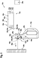
- FIG 1 shows a media application system 10a, which is designed in particular as a paint application system, in a schematic representation.
- the media application system 10a comprises a media output unit 12a for outputting at least one medium and a media storage device 14a.
- the media application system 10a comprises a base unit 16a to which the media storage device 14a and the media output unit 12a can be fastened.
- the media output unit 12a is shown in particular in a state arranged on the base unit 16a and the media storage device 14a is shown in a state separated from the base unit 16a and the media output unit 12a.
- the media application system 10a preferably comprises at least one, in particular at least partially formed separately from the media storage device 14a and / or from the media output unit 12a, Fixing unit 18a, which is provided to fix the media storage device 14a and / or the media output unit 12a on the base unit 16a.
- the base unit 16a preferably comprises at least one housing 20a on and / or in which a multiplicity of components of the media application system 10a are arranged.
- the housing 20a forms, at least in sections, a handle of the base unit 16a.
- the housing 20a preferably forms, at least in sections, a receiving area 22a of the base unit 16a, to which the media storage device 14a and the media output unit 12a can be fastened.
- the base unit 16a preferably comprises at least one reference element 24a, in particular arranged on the housing 20a in the receiving region 22a.
- the reference element 24a is preferably designed as a luminous element, in particular as an LED-illuminated sphere of light.
- the reference element 24a is designed as a radiation-free reference element, for example as a QR code, as a bar code or as another reference element that appears useful to a person skilled in the art.
- the media storage device 14a comprises a media storage unit 30a for storing the medium, a mechanical interface 32a for connection to the media output unit 12a and / or the base unit 16a.
- the media storage device 14a comprises a media transfer unit 34a for transferring the medium from the media storage unit 30a to the media output unit 12a in at least one connected state of the interface 32a with the media output unit 12a.
- the media transfer unit 34a comprises at least one porous media transfer element 36a, which is arranged on an output channel 38a of the media storage unit 30a, the media storage unit 30a comprising at least one flexible media delimitation element 40a, which is provided to divert at least one storage volume 42a of the media storage unit 30a from a compensation space 44a of the media storage unit 30a to be delimited.
- the interface 32a is provided for to connect the media transfer element 36a, depending on a connection parameter of the interface 32a, to a media output element 46a, in particular a vibration-excited, media output element 46a of the media output unit 12a for a transfer of the medium from the media storage unit 30a to the media output unit 12a.
- the media output unit 12a is preferably designed as an oscillation output unit.
- the media output unit 12a is provided to output the medium received by the media storage device 14a by means of oscillations, in particular in an ultrasonic frequency range, in particular in a media output direction 68a onto the surface 26a.
- the media output unit 12a is designed as a valve nozzle unit, as a pneumatic output unit or as another output unit that appears sensible to a person skilled in the art.
- the media output unit 12a is provided to generate media points on the surface 26a.
- the media output unit 12a in particular for generating media dots on the surface 26a, is provided, in particular in at least one printing operating mode, to output the medium in droplets, in particular in the manner of a printer.
- the media output unit 12a can preferably have at least one spray operating mode in which the media output unit 12a is provided for continuous, in particular spraying, output of the medium.
- the media output unit 12a can be releasably attached to the base unit 16a, in particular to the housing 20a of the base unit 16a.
- the media output unit 12a can be attached to the base unit 16a, in particular to the housing 20a of the base unit 16a, interchangeably with a further media output unit 12a, which in particular can have different media output properties from the media output unit 12a.
- the media application system 10a comprises an interface receptacle 48a for receiving the interface 32a of the media storage device 14a when the media storage device 14a is attached to the base unit 16a and / or the media output unit 12a.
- the interface 32a and the interface receptacle 48a are preferably designed at least partially as part of the fixing unit 18a, in particular the interface 32a and the interface receptacle 48a are provided and / or designed to be fixed to one another.
- the media storage device 14a is preferably provided to be connected to the base unit 16a and / or the media output unit 12a via the interface receptacle 48a.
- the media storage device 14a is provided to be connected to the media output unit 12a and then to be connected to the base unit 16a together with the media output unit 12a.
- the media storage unit 14a is provided to be connected to the base unit 16a and the media output unit 12a at least substantially simultaneously, in particular when the base unit 16a and the media output unit 12a are connected to one another.
- the media storage unit 30a comprises at least one media container 50a, which is at least partially delimited by at least one inner wall 52a of a housing unit 54a of the media storage device 14a.
- the media container 50a and the media delimitation element 40a delimit the storage volume 42a.
- the media storage unit 30a, in particular the media container 50a and the media delimitation element 42a is provided for receiving the at least one medium, in particular the at least one color medium.
- the media storage device 14a can be coupled, in particular operatively connected, to further components of the media application system 10a.
- the media storage device 14a, in particular the media storage unit 30a is preferably designed as an exchangeable capsule.
- the media storage device 14a in particular the media storage unit 30a, is designed as an exchangeable cartridge, as an exchangeable tank, as an exchangeable cartridge or as another media storage device that appears useful to a person skilled in the art, in particular for storing a color.
- the media storage device 14a can be releasably attached via the interface 32a to the base unit 16a of the media application system 10a, in particular to the housing 20a of the base unit 16a.
- the media storage device 14a can be attached to the base unit 16a, in particular to the housing 20a of the base unit 16a, in an exchangeable manner for a further media storage device 14a, which in particular contains a further medium.
- the medium is preferably designed at least partially as a liquid medium.
- the medium can be applied by spray and / or be provided for a print job.
- the medium is preferably designed as a color medium, for example as a dye ink, as a pigment ink, as a spray paint, as a dispersion paint, as an acrylic paint, as an, in particular water-based, acrylic paint or the like.
- a Spray chalk, a spray film or another medium that appears useful to a person skilled in the art.
- the media application system 10a in particular the media storage device 14a, is intended to use a medium which has a viscosity function that has a value between 2 mPas and 40 mPas, preferably between 10 mPas and 35 mPas and preferably between 15 mPas and 30 mPas.
- the media application system 10a, in particular the media storage device 14a is preferably provided for using a medium which, at a temperature between 5 to 50 ° C., has a dynamic surface tension that corresponds to a value between 30 mN / m and 62 mN / m.
- the fixing unit 18a preferably comprises at least one fixing element 56a arranged on the base unit 16a and / or formed by the base unit 16a, which is provided to fix the media storage device 14a and / or the media output unit 12a on the base unit 16a, in particular on the receiving area 22a .
- the fixing unit 18a preferably comprises at least one further fixing element 58a, which is arranged on the media storage device 14a and / or on the media output unit 12a and / or is formed by the media storage device 14a and / or is provided by the media storage device 14a and / or to fix the media output unit 12a on the base unit 16a, in particular on the receiving area 22a, in particular to interact with the fixing element 56a.
- the fixing unit 18a is preferably provided to fix the media storage device 14a and the media output unit 12a together, in particular in interaction with one another, on the base unit 16a.
- the media storage device 14a and the media output unit 12a are at least partially fixed to one another and / or to the base unit 16a.
- the fixing unit 18a is provided for the purpose of decoupling the media storage device 14a and the media output unit 12a at least partially from one another, in particular to be fixed independently of one another on the base unit 16a.
- other configurations of the fixing unit 18a are also conceivable.
- the fixing unit 18a can have at least one fixing element which is provided for fixing the media storage device 14a on the base unit 16a and at least one further fixing element which is provided for fixing the media output unit 12a on the base unit 16a.
- the fixing unit 18a comprises at least one actuating element 60a, in particular mounted on the base unit 16a, such as a push button, a pivot lever, a slide switch or the like, which is used to release a fixation, in particular a lock, of the media storage device 14a and / or the media output unit 12a can be operated on the base unit 16a and / or on one another.
- the media storage device 14a, the media output unit 12a and the base unit 16a are shown in FIG Figure 1 shown in a mutually decoupled state.
- the media output unit 12a is arranged on the base unit 16a, but in a position different from a fixing position.
- the media storage device 14a and / or the media output unit 12a are / is preferably provided for positive and / or non-positive, interactive fixing, in particular by means of a latching connection, by means of a snap connection, by means of a clamp connection or the like, to one another and / or to the base unit 16a .
- the media storage device 14a and / or the media output unit 12a are / is provided for interactive fixation by means of a magnetic connection, by means of a suction connection, by means of a Velcro connection or the like, to one another and / or to the base unit 16a.
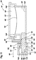
- the media output unit 12a comprises the media output element 46a, an actuator element 62a for exciting the media output element 46a and a control and / or regulating unit 64a for controlling and / or regulating the actuator element 62a for exciting the media output element 46a.
- the control and / or regulating unit 64a is preferably provided to set at least one control parameter of the actuator element 62a to excite the media output element 46a, in particular dynamically.
- the control and / or regulating unit 64a has at least one programmable FPGA or the like.
- the media output element 46a is at least partially elastic, in particular elastically deformable, in particular can be excited to vibrate.
- the media output element 46a preferably has a plurality of media passage openings through which the medium can be discharged and which in particular are in the Figure 2 are only indicated.
- the media passage openings are designed in particular as a perforation or hole in the media output element 46a.
- the media output element 46a is designed in particular as an ultrasound membrane, as an ultrasound plate or the like.
- the media output element 46a is preferably designed in the shape of a circular area when viewed in a main plane of extent of the media output element 46a, which corresponds in particular to a membrane plane 67a of the media output unit 12a.
- the media output element 46a viewed in the main plane of extent of the media output element 46a, is embodied as elliptical, polygonal, for example, square or triangular, or the like.
- the media output element 46a is preferably provided to receive the medium from the media transfer element 36a and to output it in the direction of the surface 26a, in particular in a directed manner (see FIG Figure 1 ).
- the actuator element 62a is preferably designed as a piezo element, in particular as a piezo crystal.
- the actuator element 62a designed as a piezo element changes its shape as a result of the application of an electrical voltage to the actuator element 62a designed as a piezo element, which in particular leads to a vibration of the media output element 46a due to a mechanical coupling of the actuator element 62a designed as a piezo element to the media output element 46a.
- the actuator element 62a is designed as a MEMS actuator (microelectromechanical system actuator), as an ultrasonic converter or as another actuator element 62a that appears useful to a person skilled in the art.
- the actuator element 62a is designed in the shape of a circular ring and is arranged coaxially around a central axis 66a of the media output element 46a on the media output element 46a.
- the actuator element 62a is preferred at least electrically connected to the control and / or regulating unit 64a.
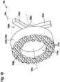
- the media output unit 12a comprises at least one suspension (see FIG Figure 8 ), which is provided to counteract damping of a movement of the media output element 46a, in particular to output the medium, via contact with the media storage device 14a, in particular the media transmission element 36a, and / or to minimize the damping.
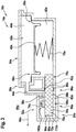
- FIG 3 a schematic cross section of the media storage device 14a is shown, in particular along a longitudinal axis of the media transfer element 36a and / or the media output direction 68a.
- the housing unit 54a of the media storage device 14a delimits the compensation space 44a and the storage volume 42a via inner walls 52a of the housing unit 54a.
- the compensation space 44a and the storage volume 42a are formed at least fluidly separated from one another via the media delimitation element 40a.
- the media delimitation element 40a is connected to the inner walls 52a via flexible areas 69a.
- the media delimitation element 40a is provided to adapt the storage volume 42a to an amount of the medium arranged within the storage volume 42a.
- the media storage unit 30a comprises at least one restoring element 70a, which is provided to apply a restoring force to the media limiting element 40a.
- the restoring element 70a in particular the restoring force, particularly preferably counteracts the capillary action of the media transfer element 36a, a compression pressure of the medium within the storage volume 42a and / or a fluid pressure of the compensation chamber 44a.
- the restoring element 70a is preferably arranged on the media limiting element 40a.
- the restoring element 70a is designed as a spring, in particular a compression spring.
- the media delimitation element 40a is designed as a partition which can be moved within the media container 50a via the flexible areas 69a.
- the media delimitation element 40a is designed as a membrane, a film or the like, which in particular at least partially delimits the storage volume 42a. It is also conceivable that the media delimitation element 40a the storage volume 42a, in particular with the exception of the output channel 38a, at least for the most part, in particular at least substantially completely, limited.
- the media delimitation element 40a is preferably arranged between the storage volume 42a and the compensation space 44a.
- the interface 32a is preferably provided, in particular in a state connected to the media output unit 12a and / or the interface receptacle 48a, to arrange the media transfer element 36a at a predetermined distance from the media output element 46a and / or, in particular directly, to arrange it on the media output element 46a (see FIG Figure 1 ).
- the media storage device 14a comprises at least one, in particular removable, cover cap 72a for covering the interface 32a, in particular the media transmission element 36a.
- the media transfer element 36a is preferably arranged in a transfer position, in particular for transferring the medium from the media storage unit 30a to the media output unit 12a and / or from the media transfer element 36a to the media output element 46a.
- the media transfer element 36a is at least fluidly connected to the media delimitation element 40a, in particular the storage volume 42a.
- the media transfer element 36a preferably delimits the storage volume 42a at least partially, in particular in a region of the outlet channel 38a.
- the media transfer element 36a is preferably arranged and / or fastened in a stationary manner relative to the interface 32a, in particular a connection surface 74a of the interface 32a for contact with the media output unit 12a and / or the interface receptacle 48a, and / or has a permanent, in particular in every operating state, a constant distance from the interface 32a.
- the media transmission element 36a is preferably arranged at least partially, in particular at least largely, within the output channel 38a.
- the outlet channel 38a is particularly preferably fluidically connected to the storage volume 42a.
- the media transfer element 36a preferably at least substantially completely fills the outlet channel 38a, in particular viewed from the storage volume 42a, in particular the medium exclusively by flowing through and / or flowing through the, in particular porous, media transfer element 36a can be removed from the storage volume 42a through the outlet channel 38a.
- the media transfer element 36a is preferably designed to be absorbent, in particular provided to absorb at least part of the medium and to transport it out of the media delimitation element 40a, in particular the storage volume 42a.
- the media transfer element 36a is provided to transport the medium by means of a capillary effect, in particular according to a wick principle.
- the medium preferably flows during a media output, in particular through the media output unit 12a, due to a difference in concentration of the medium between an end piece 76a of the media transfer element 36a arranged in the storage volume 42a and an end piece 76a of the media transfer element 36a arranged outside the storage volume 42a, in particular with the media output unit 12a and / or the media output element 46a end piece 78a of the media transfer element 36a that is in contact / to be brought into contact along the media transfer element 36a, in particular out of the storage volume 42a.
- the media transfer element 36a is at least partially porous.
- the media transfer element 36a is preferably formed like a sponge, in particular as a transport sponge.
- the media transfer element 36a is designed like a wick, glass fiber, tube-like or the like and / or is made up of a multiplicity of capillary fibers.
- the media transfer element 36a preferably has a cylinder-like, in particular circular cylinder-like, shape.
- the media transfer element 36a in particular the end piece 78a of the media transfer element 36a arranged outside the storage volume, is preferably in direct contact with the media output element 46a of the media output unit 12a, which is in particular oscillating and / or vibrated for a media output.
- the media output element 46a is provided to receive the medium to be output from the media transfer element 36a.
- the media transfer element 36a is designed in two parts.
- the media storage unit 30a, in particular the media delimitation element 40a, is provided in particular to receive the medium for storage within the storage volume 42a.
- the interface 32a preferably surrounds an output region 80a of the output channel 38a at least for the most part, in particular at least substantially completely.
- the end piece 78a of the media transfer element 36a which is arranged outside the storage volume 42a, is preferably arranged on the output region 80a of the output channel 38a.
- a line element 82a delimiting the output channel 38a and / or enclosing the media transmission element 36a is designed as part of the interface 32a, and in particular in at least one operating state, in particular a connected state of the interface 32a, on the media output unit 12a and / or the Interface receptacle 48a is applied.
- the line element 82a is formed in one piece with the housing unit 54a.
- the line element 82a in particular the outlet channel 38a, is preferably of tubular or channel-like design, for example with a rectangular, square, round and / or circular cross-sectional area.
- the media transfer element 36a preferably has an at least substantially cylindrical or cubic basic shape.
- the media transfer element 36a is provided to generate a negative pressure in the storage volume 42a by removing media from the storage volume 42a and to convey the removed medium to the media output element 46a.
- the media transfer element 36a comprises, in particular on an end piece 78a of the media transfer element 36a arranged outside the storage volume 42a, at least one output surface 84a, which is provided to output the medium to the media output unit 12a, in particular the media output element 46a.
- the output surface 84a lies in at least one connected state of the interface 32a, in particular flat on the media output unit 12a, in particular the media output element 46a.
- the connecting surface 74a of the interface 32a and the output surface 84a of the media transfer element 36a are preferably arranged stationary to one another and / or have a constant distance from one another, in particular in every operating state.
- the media transfer element 36a is provided to transfer the medium from the storage volume 42a, in particular in the media output direction 68a, to the output surface 84a, in particular the media output unit 12a and / or the media output element 46a.
- the media transfer element 36a is preferably provided to generate the negative pressure by interacting with the restoring element 70a, in particular the medium removed from the storage volume 42a via the media transfer element 36a reducing a pressure in the storage volume 42a and the restoring element 70a reducing the storage volume 42a due to pressure the media limiting element 40a counteracts.
- the negative pressure in the storage volume 42a counteracts an uncontrolled outflow of the medium from the storage volume 42a via the media transfer element 36a.
- the negative pressure preferably counteracts the restoring force of the restoring element 70a.
- the restoring element 70a and / or the media transfer element 36a are / is preferably designed such that the medium flows at least essentially constantly from the storage volume 42a via the media transfer element 36a, in particular via the capillary action of the media transfer element 36a.
- the media transfer unit 34a in particular the media transfer element 36a, is designed to be exchangeable, in particular at least essentially non-destructively.
- the media transfer unit 34a in particular the media transfer element 36a, can be removed at least essentially non-destructively.
- the media transfer unit 34a, in particular the media transfer element 36a is provided when the storage volume 42a is filled, during maintenance, in particular cleaning, the media storage device 14a, in particular the media storage unit 30a and / that when the media output element 46a is changed, in particular to a other media output element 46a which is different from the media output element 46a and which, for example, has a different rigidity, Excitation frequency or the like. Has to be removed and / or changed.
- the media transfer element 36a is provided to filter a medium to be transferred to the media output element 46a.
- the media transfer element 36a is preferably provided to transport the medium from the storage volume 42a to the media output unit 12a, in particular the media output element 46a, with an at least substantially uniform density, in particular with regard to a distribution of the medium within the media transfer element 36a.
- the media output element 46a is particularly preferably provided to filter the medium to be transferred from foreign bodies, dirt and / or air inclusions. It is conceivable that the media transfer element 36a has a multi-part design and / or the media transfer unit 34a has a further media transfer element 36a for filtering the medium.
- the media transfer element 36a is formed from a filter layer and a transport layer, which in particular are not shown in the figures, the filter layer in particular being provided for filtering the medium to be transferred and the transport layer being provided for transferring the medium.
- the media transfer unit 34a in particular of the media transfer element 36a, are also conceivable.
- the media storage device 14a comprises a sensor unit 86a for determining a fill level parameter of the media storage unit 30a on the media transfer unit 34a.
- the sensor unit 86a is provided to determine the fill level parameter independently of a connection state of the media storage device 14a, in particular the interface 32a.
- the sensor unit 86a is provided to determine the fill level parameter by interacting with at least one, in particular external, computing unit and / or one, in particular external, sensor element of the media application system 10a, which in particular is separate and / or spaced from the media storage device 14a is formed.
- the sensor unit 86a has two sensor elements 88a which are provided to detect at least one throughput parameter of the media transfer element 36a in order to determine the fill level parameter.
- the sensor elements 88a are preferably each arranged on the media transfer element 36a and / or the line element 82a.
- the sensor elements 88a preferably each at least partially delimit the output channel 38a.
- the sensor elements 88a are in contact with the media transfer element 36a.
- the sensor elements 88a are preferably designed as optical, electrical and / or movable sensors.
- the throughput parameter is designed as an electrical resistance of the media transfer element 36a.
- the sensor elements 88a preferably rest on an outer surface 90a of the media transfer element 36a.
- the sensor elements 88a are at least electrically conductively connected to the media transmission element 36a.
- the sensor elements 88a are designed as printed circuit boards which are at least electrically connected to one another.
- the sensor elements 88a are preferably arranged on the line element 82a and in particular at least partially delimit the outlet channel 38a.
- the sensor unit 86a is preferably provided to transmit at least one electrical signal, in particular an electrical current and / or an electrical voltage, through the media transmission element 36a from one sensor element 88a to another sensor element 88a, wherein in particular the electrical resistance of the media transmission element 36a is detected .
- the sensor unit 86a is preferably provided to determine the fill level parameter of the media storage unit 30a as a function of the electrical resistance of the media transfer element 36a.
- the sensor unit 86a comprises at least one electronics unit 92a for determining the fill level parameter as a function of the electrical resistance of the media transmission element 36a.
- the sensor unit 86a, in particular the electronics unit 92a is preferably provided, for example by comparing a detected value of the electrical resistance of the media transfer element 36a with at least one reference value of the electrical resistance of the media transfer element 36a, which is assigned to at least one value of the fill level parameter, the fill level parameter determine.
- the fill level parameter is designed as an amount of medium stored within the media transfer element 36a, which medium is removed from the storage volume 42a via the media transfer element 36a.
- a certain value of the quantity of the medium stored within the media transfer element 36a preferably enables a conclusion, in particular a calculation and / or estimate of an amount of medium remaining within the storage volume 42a and / or at least a statement as to whether the fill level of the storage volume 42a is below a specific level.
- other configurations of the sensor unit 86a, in particular the sensor elements 88a are also conceivable, for example with a number of sensor elements 88a other than two.
- the throughput parameter and / or the fill level parameter are designed differently from an electrical resistance of the media transmission element 36a, for example as a capacitance, as an inductance, as an optical density or the like of the media transmission element 36a.
- the interface 32a comprises a fluid channel 94a, which is fluidly formed separately from the storage volume 42a and is provided to provide a negative pressure in the compensation space 44a for filling the storage volume 42a.
- the fluid channel 94a is designed as a volume limited by the interface 32a and / or the housing unit 54a of the media storage device 14a, in particular the media storage unit 30a and / or the media transfer unit 34a, which is provided in particular for a line of a fluid, in particular air.
- the fluid channel is preferably connected to the compensation chamber in terms of fluid technology.
- the fluid channel 94a is preferably provided to fluidically connect the compensation space 44a to an environment 96a surrounding the media storage device 14a.
- the fluid channel 94a is provided to be connected to at least one external compression unit via the interface 32a in order to fill the storage volume 42a, which in particular is not shown in the figures.
- the fluid channel 94a in particular a part of the fluid channel on the surrounding area, is preferably arranged in a vicinity of the line element 82a and / or the media transfer element 36a.
- the fluid channel 94a extends at least substantially parallel to the media transfer element 36a from the compensation space 44a to the interface 32a.
- other configurations of the fluid channel 94a are also conceivable.
- the interface 32a comprises a sealing unit 98a, which is provided for the purpose of opening at least one output region 80a of the interface 32a which is arranged on the media transfer element 36a when the interface 32a is connected to close at least substantially airtight with the media output unit 12a.
- the sealing unit 98a of the interface 32a is preferably provided to counteract a pressure difference caused by a movement of the media output element 46a between the output area 80a and the environment 96a surrounding the interface 32a, in particular the sealing unit 98a of the interface 32a, in particular to prevent a flow of fluid between the output area 80a and the environment 96a.
- the sealing unit 98a of the interface 32a is preferably provided to counteract, in particular at least substantially avoid, air flows within the output region 80a, in particular in the connected state of the interface 32a.
- the sealing unit 98a of the interface 32a preferably comprises at least one sealing element 100a which at least substantially completely encloses the output region 80a in at least one plane, in particular a plane which is at least substantially perpendicular to the media output direction 68a.
- the sealing element 100a is preferably embodied at least substantially in the shape of a ring.
- the sealing element 100a is formed from a flexible sealing material such as rubber or plastic.
- the sealing unit 98a of the interface 32a is preferably provided for at least essentially airtight sealing of the discharge area 80a to which a negative pressure is applied.
- the interface 32a in particular viewed in at least one plane oriented at least substantially parallel to the media output direction 68a, has at least one undercut 102a, which extends at least substantially completely around the output area, in particular in a plane oriented at least substantially perpendicular to the media output direction 68a 80a extends.
- the sealing element 100a is preferably arranged at least partially within the undercut 102a.
- the media transfer unit 34a comprises at least one, in particular flexible, shaping and / or sealing element 112a (see FIG Figures 6 to 8 ), which is provided to adapt at least one output parameter of the media transmission element 36a as a function of at least one connection parameter of the interface 32a.
- the shaping and / or sealing element 112a is in FIG Figure 3 only indicated.
- the media transfer element 36a is intended to be applied directly to the media output element 46a, in particular when the interface 32a is connected.
- the media application system 10a is shown in a region of the interface 32a and the interface receptacle 48a in an interconnected state of the media storage device 14a and the media output unit 12a.
- the media storage device 14a is connected to the media output unit 12a via the fixing unit 18a.
- the fixing unit 18a comprises two actuation elements 104a designed as push buttons for releasing the connection between the media storage device 14a and the media output unit 12a.
- the two actuating elements 104a are arranged laterally on the housing unit 54a. However, it is also conceivable that the two actuating elements 104a are arranged on the media output unit 12a and / or the base unit 16a.
- the two actuating elements 104a are intended to be actuated in mutually facing directions, with in particular an inclined fixing surface 106a of the interface 32a being moved onto an inclined fixing surface 108a of the interface receptacle 48a designed to correspond to the fixing surface 106a (see also Figure 8 ).
- the media storage device 14a and the media output unit 12a are moved apart in opposite directions and, in particular, a connection between the media storage device 14a and the media output unit 12a is separated (see FIG Figure 8 ).
- FIG. 5 an exemplary sequence of a method 174a for filling the media storage device 14a is shown.
- the media transfer element 36a is connected to an external media reservoir, wherein in particular the media transfer element 36a is moved and / or immersed directly into the medium and / or the media reservoir.
- the fluid channel 94a is at least fluidly connected to an external compression unit.
- step 180a of method 174a the Interface 32a of the media storage device 14a, in particular via the external compression unit, a negative pressure is provided at the compensation space 44a arranged on the media delimitation element 40a of the media storage device 14a to be filled, whereby the at least one medium, in particular from the external media reservoir, is in the media delimitation element 40a, in particular the storage volume 42a, is conducted.
- the media transfer element 36a is removed from the interface 32a in order to fill the storage volume 42a, wherein in particular the storage volume 42a can be filled directly via a negative pressure at the compensation space 44a.
- FIG 6 An alternative embodiment of a media storage device 14b for a media application system 10b is shown in an area of an interface 32b of the media storage device 14b.
- the media storage device 14b comprises a media storage unit 30b for storing at least one medium, an, in particular mechanical, interface 32b for a connection to a media output unit 12b of the media application system 10b (in Figure 6 not shown) and a media transfer unit 34b for transferring the medium from the media storage unit 30b to the media output unit 12b in at least one connected state of the interface 32b with the media output unit 12b.
- the media transfer unit 34b has a porous media transfer element 110b which is arranged on an output channel 38b of the media storage unit 30b.
- the one in the Figure 6 shown Media storage device 14b has an at least substantially analogous configuration to that in the description of FIG Figures 1 to 5 described media storage device 14a, so that with respect to an embodiment of the Figure 6 illustrated media storage device 14b at least essentially to the description of the Figures 1 to 5 can be referenced.
- the media transfer unit 34b of the media storage device 14b shown in Figure 6 preferably has a flexible shaping and / or sealing element 112b, which is provided to adapt at least one output parameter of the media transfer element 110b as a function of at least one connection parameter of the interface 32b.
- the output parameter of the media transfer element 110b is designed as a shape of an output area 84b of the media transfer element 110b, which is arranged in particular on the shaping and / or sealing element 112b and / or as a density of the media transfer element 110b, in particular in a region of the output area 84b is.
- the output parameter is designed as a shape of the output surface 84b, which, in particular by interacting with the shaping and / or sealing element 112b and / or a media output element 46b of the media output unit 12b (in Figure 6 not shown) influences a two-dimensional distribution and / or a quantity of the medium to be transmitted.
- the media transfer element 110b is fluidly connected to the storage volume 42b and is provided to transfer the medium from the storage volume 42b, an output channel 38b and / or an output channel of the media transfer unit 34b to the shaping and / or sealing element 112b, the medium in particular being transferred through the Shaping and / or sealing element 112b is output to the media output element 46b.
- the media storage device 14b comprises at least one further media transmission element, which in particular is structurally identical and / or analogous to that in the Figures 1 to 5 described media transfer element 36a is formed.
- the media storage device 14b comprises at least one media delimitation element, which in particular is structurally identical and / or analogous to that in the Figures 1 to 5 media limiting element 36a described is formed.
- the shaping and / or sealing element 112b is designed as a membrane and, in particular depending on a shape of the shaping and / or sealing element 112b, has at least one fluid-permeable state and at least one fluid-impermeable state. It is also conceivable that the shaping and / or sealing element 112b is designed as a fabric, as a porous layer or the like. The shaping and / or sealing element 112b preferably has a different shape in the fluid-permeable state, in particular with regard to a side facing the media output element 46b, than in the fluid-impermeable state.
- the shaping and / or sealing element 112b preferably has the fluid-impermeable state in a state formed at a distance from the media output unit 12b and / or in an unconnected state of the interface 32b.
- the shaping and / or sealing element 112b preferably has the fluid-permeable state in a state connected to and / or arranged with the media output unit 12b and / or in a connected state of the interface 32b.
- the shaping and / or sealing element 112b is preferably stretched over the output surface 84b of the media transfer element 110b and, in particular, rests on the output surface 84b over the entire surface.
- the shaping and / or sealing element 112b is impermeable to the medium in the fluid-impermeable state.
- the shaping and / or sealing element 112b is designed to be permeable to the medium in the fluid-permeable state.
- the shaping and / or sealing element 112b preferably delimits a multiplicity of openings which, in the fluid-impermeable state, are designed in such a way that they are designed to be impermeable to the medium. In particular, the openings are not shown in the figures.
- the shaping and / or sealing element 112b is preferably provided to guide the medium via capillarity from the media transfer element 36b to the media output unit 12b, in particular the media output element 46b.
- the shaping and / or sealing element 112b is designed in such a way that a capillary effect acts on the medium as a function of a contact of the shaping and / or sealing element 112b with the media output element 46b.
- the shaping and / or sealing element 112b is designed in such a way that when there is contact the capillary effect acts on the medium at the media output element 46b, the medium in particular being conducted from the media transfer element 36b through the shaping and / or sealing element 112b to the media output element 46b.
- the shaping and / or sealing element 112b is designed in such a way that in a state of the shaping and / or sealing element 112b that is separate from the media output element 46b, in which, in particular, air is applied to the shaping and / or sealing element 112b, which is on or in
- the medium arranged on the shaping and / or sealing element 112b is at least essentially free of forces, wherein in particular the shaping and / or sealing element 112b is designed to be fluid-impermeable.
- the shaping and / or sealing element 112b is designed in such a way that the openings of the shaping and / or sealing element 112b during a transition to the fluid-permeable state, in particular by a deformation and / or stretching of the shaping and / or / or sealing element 112b, are opened, widened and / or released, in particular the openings being designed to be permeable to the medium.
- the shaping and / or sealing element 112b is in the fluid-impermeable state, in the state formed at a distance from the media output unit 12b and / or in the unconnected state of the interface 32b in a tensioned state, with in particular the shaping and / or sealing element 112b over the media transfer element 110b, in particular the output surface 84b, is tensioned.
- the shaping and / or sealing element 112b is preferably attached to an edge surface 114b of the output channel 38b and / or of the output channel.
- the shaping and / or sealing element 112b is materially connected to the edge surface 114b of the output channel 38b and / or the output channel, for example by means of an adhesive connection, a clamp connection or the like Figure 6 shown in the fluid impervious state.
- the shaping and / or sealing element 112b is intended to be placed directly on a movable media output element 46b, in particular a membrane, of the media output unit 12b, in particular in at least one operating state.
- the shaping and / or sealing element 112b has at least one central axis 116b, which in particular is arranged at least substantially parallel to a media output direction 68b.
- the shaping and / or sealing element 112b in particular in the connected state of the interface 32b and / or a state of the shaping and / or sealing element 112b arranged on the media output element 46b, is preferably arranged and / or designed in such a way that a central axis of the media output element 46b is identical to the central axis 116b of the shaping and / or sealing element 112b.
- the shaping and / or sealing element 112b is provided to be placed centrally on the media output element 46b. It is conceivable that the shaping and / or sealing element 112b is provided to lie flat against the media output element 46b in at least one operating state.
- the media transfer element 110b is provided for a transfer of the medium from the media storage unit 30b to the shaping and / or sealing element 112b, the shaping and / or sealing element 112b resting on the output surface 84b of the media transfer element 110b and in particular being provided for a shape of the Media transfer element 110b, in particular the output surface 84b, to be specified.
- the shape of the media transfer element 110b and / or the shaping and / or sealing element 112b in particular in the disconnected state of the interface 32b and / or in a state of the media transfer unit 34b spaced apart from the media output unit 12b (see FIG Figure 6 ), an at least substantially domed, spherical, conical or dome-shaped basic shape.
- the shape of the media transfer element 110b and / or the shaping and / or sealing element 112b in particular in the disconnected state of the interface 32b and / or in a state of the media transfer unit 34b at a distance from the media output unit 12b, in at least one sectional plane, in particular through the Central axis 116b of the shaping and / or sealing element 112b, a circular arc, parabolic or peg-shaped contour.
- the shaping and / or sealing element 112b is provided, when connected to the media output unit 12b and / or the interface receptacle 48b, in particular by interacting with the media output element 46b at least in sections, in particular in an area around the central axis of the shaping and / or sealing element 112b, against the media output direction 68b and / or pressed in, preferably the shaping and / or sealing element 112b from the fluid-impermeable state in the fluid-permeable state is transferred.
- the media transfer unit 34b comprises a tensioning element 118b, which is provided to apply a tensioning force to the shaping and / or sealing element 112b against the media output direction 68b of the media transfer unit 34b.
- the tensioning element 118b designed in particular as a spring element, is designed as a compression spring.
- the tensioning element 118b is preferably arranged at least partially, in particular at least largely, within the output channel 38b and / or the output channel.
- the tensioning element 118b is preferably arranged with one end of the tensioning element 118b on a wall 120b of the media transfer unit 34b and / of the media storage unit 30b that delimits the output channel 38b and / or the output channel.
- the clamping element 118b is preferably arranged with another end of the clamping element 118b, which is in particular arranged opposite the end, on the media transfer element 110b, in particular a force-absorbing surface 122b of the media transfer element 110b and / or a support element 124b of the media transfer unit 34b, which is located on the media transfer element 110b, in particular the force-absorbing surface 122b, is arranged, in particular rests.
- the media transfer unit 34b comprises the support element 124b, which is provided to transfer the clamping force at least substantially uniformly over an output surface 84b of the shaping and / or sealing element 112b to the shaping and / or sealing element 112b.
- the support element 124b is provided to transmit the clamping force at least essentially uniformly over the force-absorbing surface 122b of the media transmission element 110b to the media transmission element 110b.
- the support element 124b is fluid-permeable and / or permeable to the medium in the media output direction 68b educated.
- the support element 124b delimits a multiplicity of passages 126b for conducting the medium to the medium transmission element 110b.
- the feedthroughs 126b are distributed over a maximum transverse extent 128b of the support element 124b and / or over a support surface 130b of the support element 124b, which in particular is / is aligned at least substantially perpendicular to the media output direction 68b.
- the support surface 130b is preferably provided to be placed against the media transfer element 110b and in particular to at least substantially avoid and / or counteract a slipping of the media transfer element 110b relative to the support element 124b.
- the support element 124b has at least one adhesive structure 132b on the support surface 130b, which is formed, for example, from a plurality of projections, grooves and / or shafts which are provided to engage the media transmission element 110b, in particular the force-absorbing surface 122b .
- the support element 124b is preferably arranged at least for the most part, in particular at least substantially completely, within the output channel and / or the output channel 38b.
- the support element 124b is arranged between the tensioning element 118b and the media transfer element 110b.
- the support element 124b is designed in particular in the form of a plate and has a circular base area.
- the passages 126b extend over an entire thickness of the support element 124b, in particular from a side of the support element 124b facing the clamping element 118b to the support surface 130b and / or a side of the support element 124b facing the media transfer element 110b.
- the interface 32b comprises a sealing unit 98b, which is provided to at least essentially airtight at least one output area 80b of the interface 32b arranged on the shaping and / or sealing element 112b when the interface 32b is connected to the media output unit 12b and / or the interface receptacle 48b to close.
- the sealing unit 98b of the interface 32b is preferably provided to counter a pressure difference between the output area 80b and an interface 32b, in particular the sealing unit, caused by a movement of the media output element 46b and / or output of the medium at the shaping and / or sealing element 112b 98b of the interface 32b, to counteract the surrounding environment 96b, in particular to prevent a fluid flow between the output region 80b and the environment 96b.
- the media storage unit 30b comprises at least one, in particular flexible, media delimitation element which in particular at least partially delimits the storage volume 42b.
- the media storage device 12b comprises at least one reset element, which is provided in particular to act on the media delimitation element and to provide a negative pressure in the storage volume 42b.
- the tensioning element 118b is designed as a restoring element, the tensioning element 118b in particular being provided to perform functions of a restoring element.
- the restoring element is preferably provided to apply a restoring force to the flexible media limiting element.
- the restoring element, in particular the restoring force particularly preferably counteracts the capillary action of the media transfer element 110b, a compression pressure of the medium within the storage volume 42b and / or a fluid pressure of a compensation chamber.
- FIG. 11 shows an exploded view of the media storage device 14b in a region of the interface 32b.
- the media transfer element 110b has a cylindrical basic shape in a state of the media transfer element 110b that is spaced apart from the shaping and / or sealing element 112b.
- the shaping and / or sealing element 112b is provided to adapt a shape of the media transfer element 110b when the shaping and / or sealing element 112b is mounted and / or is arranged on the media transfer element 110b.
- the shaping and / or sealing element 112b, the media transfer element 110b, the support element 124b and the tensioning element 118b are in particular each formed in one piece and rest against one another when the media transfer unit 34b is in an assembled state.
- the shaping and / or sealing element 112b, the media transfer element 110b, the support element 124b and the tensioning element 118b are at least partially materially connected to one another.
- the media storage device 14b has at least one sensor unit for determining a fill level parameter of the media storage unit on the media transfer unit, for example similar to the sensor unit 86a (see Figure 3 ). It is preferably conceivable that the sensor unit has at least one sensor element which is provided to detect at least one throughput parameter of the media transfer element 110b in order to determine the fill level parameter, the throughput parameter preferably being designed as an electrical resistance of the media transfer element 110b.
- FIG 8 Another alternative embodiment of a media storage device 14c of a media application system 10c is shown.
- the media application system 10c comprises the media storage device 14c and a media output unit 12c, which has at least one movable media output element 46c for a directional output of a medium.
- the media storage device 14c comprises a media storage unit 30c for storing at least one medium, a mechanical interface 32c for connection to the media output unit 12c of the media application system 10c and a media transfer unit 34c for transferring the medium from the media storage unit 30c to the media output unit 12c in at least one connected state the interface 32c with the media output unit 12c.
- the media transfer unit 34c comprises a porous media transfer element 110c, which is arranged on an output channel 38c of the media storage unit 30c.
- the media transfer unit 34c comprises a flexible shaping and / or sealing element 112c, which is provided to adapt at least one output parameter of the media transfer element 110c as a function of at least one connection parameter of the interface 32c.
- the media application system 10c comprises an interface receptacle 48c for a receptacle of the interface 32c of the media storage device 14c to a connection of the media storage device 14c and the media output unit 12c.
- the media storage device 14c shown has an at least essentially analogous configuration to that in the description of FIG Figures 6 and 7th described media storage device 14b, so that with respect to an embodiment of the Figure 8 illustrated media storage device 14c at least essentially to the description of the Figures 6 and 7th can be referenced.
- media storage device 14b described has the shaping and / or sealing element 112c of the media transfer unit 34c in the Figure 8 illustrated media storage device 14c preferably has a different shape.
- the shaping and / or sealing element 112c is shown in FIG Figure 8 shown in a state arranged on the media output element 46c, the shaping and / or sealing element 112c in particular having a planar transfer surface 134c via which the shaping and / or sealing element 112c transfers the medium to the media output element 46c.
- the media transfer element 110c of the media transfer unit 34c delimits a plurality of passages 136c which transfer the medium from a storage volume 42c of the media storage device 14c via a support element 124c of the media transfer unit 34c to the shaping and / or sealing element 112c.
- the feedthroughs 136c delimited by the media transfer element 110c are preferably provided to transfer the medium along the transfer surface 134c at least substantially uniformly to the shaping and / or sealing element 112c.
- the interface 32c comprises a sealing unit 98c, which is provided to close at least one output region 80c of the interface 32c arranged on the shaping and / or sealing element 112c at least substantially airtight when the interface 32c is connected to the media output unit 12c.
- the interface receptacle 48c comprises a sealing unit 138c, which is provided to the output area 80c of the interface 32c, on which the media output element 46c and a shaping and / or sealing element 112c of the media storage device 14c are arranged, in particular by interacting with a sealing unit 98c of the interface 32c to close at least substantially airtight.
- the interface receptacle 48c is provided for cooperation with the interface 32c of the media storage device 14c when the media storage device 14c is connected to the media output unit 12c.
- the sealing unit 138c of the interface receptacle 48c is preferably designed to correspond to the sealing unit 98c of the interface 32c, with at least one sealing surface 140c and / or a sealing element 142c of the sealing unit 138c of the interface receptacle 48c resting on a sealing element 100c of the sealing unit 98c of the interface 32c.
- the sealing unit 98c of the interface 32c and the sealing unit 138c of the interface receptacle 48c each comprise a sealing element 100c, 142c.
- the sealing element 100c of the sealing unit 98c of the interface 32c is designed as a sealing ring, in particular made of rubber and / or a plastic.
- the sealing elements 100c, 142c each have a wedge-shaped contour.
- the sealing elements 100c, 142c each have an inclined sealing surface 140c, 144c.
- the sealing element 100c of the sealing unit 98c of the interface 32c rests against an undercut 102c of the interface 32c and comprises the sealing surface 144c which is beveled towards the outside.
- the sealing element 142c of the sealing unit 138c of the interface receptacle 48c is formed in one piece with a housing unit of the media output unit 12c and has an inwardly beveled sealing surface 140c.
- the sealing element 100c of the interface 32c and the sealing element 142c of the interface receptacle 48c are preferably provided to cooperate in an at least substantially airtight sealing of the dispensing area 80c, the sealing surfaces 140c, 144c preferably being arranged and / or lying on top of one another.
- the output area 80c is preferably formed by the media storage device 14c and the media output unit 12c.
- the media output element 46c and the shaping and / or sealing element 112c each at least partially delimit the output region 80c.
- the sealing elements 100c, 142c are preferably acted upon by at least one fixing force against one another via a fixing unit 18c of the media application system 10c.
- the media output unit 12c comprises a suspension 146c, which is provided to counteract damping of a movement of the media output element 46c, in particular to output the medium, via the shaping and / or sealing element 112c of the media storage device 14c and / or to minimize the damping.
- the suspension 146c preferably encloses the media output element 46c at least substantially completely in a main plane of extent of the media output element 46c and / or a plane oriented at least substantially perpendicular to the media output direction 68c.
- the suspension 146c preferably encloses the media output element 46c in an at least substantially parallel to the media output direction 68c and / or to the main plane of extent of the media output element 46c, viewed in an edge region 148c of the media output element 46c, at least for the most part.
- the suspension 146c of the media output unit 12c in the edge region 148c of the media output element 46c engages around a central axis of the media output element 46c.
- the media output element 46c suspension is positively and / or non-positively connected to the sealing unit 138c of the interface receptacle 48c and / or to the housing unit of the media output unit 12c.
- the media output element 46c is designed to be removable or exchangeable by means of the suspension 146c.
- the suspension 146c is preferably provided to close the media output element 46c in the edge region 148c, in particular with regard to the output region 80c, at least substantially airtight.
- the suspension 146c preferably delimits at least one, in particular circular, recess 150c for receiving the media output element 46c.
- the suspension 146c is preferably embodied in the shape of a circular ring.
- the media output element 46c is at least partially elastic, in particular elastically deformable, in particular can be excited to vibrate.
- the media output element 46c preferably has a plurality of media passage openings through which the medium can be discharged, which in particular are in the Figure 8 are not shown.
- the media output unit 12c comprises a further sealing element, which in particular is in the Figure 8 is not shown.
- the further sealing element is arranged on the suspension 146c and is provided to close the media output element 46c in the edge region 148c, in particular with regard to the output region 80c, at least essentially airtight.
- the media passage openings are designed in particular as a perforation or hole in the media output element 46c.
- the media output element 46c is designed in particular as an ultrasonic membrane, an ultrasonic plate or the like.
- the media output element 46c viewed in a main plane of extent of the media output element 46c, is preferably configured in the shape of a circular area. Alternatively, it is conceivable that the media output element 46c, viewed in the main plane of extent of the media output element 46c, is embodied as elliptical, polygonal, for example, square or triangular, or the like.
- the media output unit 12c preferably comprises at least one actuator element 62c, in particular as a piezo element is designed to stimulate, in particular oscillating, the media output element 46c.
- the actuator element 62c is arranged on the media output element 46c, in particular the edge region 148c.
- the suspension 146c preferably encloses the actuator element 62c along a central axis 152c of the media output element 46c, the suspension 146c and / or the actuator element 62c at least for the most part, in particular at least substantially completely. In particular, the suspension 146c limits conductor guides for electrical control of the actuator element 62c.
- the suspension 146c has two grooves 156c in an outer region 154c, which is arranged in particular on an outer side of the suspension 146c facing away from the central axis 152c of the suspension 146c, the actuator element 62c and / or the media output element 46c.
- the two grooves 156c each extend along the central axis 152c of the suspension 146c, the actuator element 62c and / or the media output element 46c, viewed at two ends of the suspension 146c facing away from one another.
- the two grooves 156c are each provided to interact with at least one extension 158c of the housing unit 52c of the media output unit 12c which engages in one of the grooves 156c to fix the suspension 146c.
- the housing unit 52c forms at least one extension 158c, in particular a plurality of extensions 158c, which is provided in particular to engage in grooves 156c delimited by the suspension in order to fix the suspension 146c.
- the suspension 146c is formed, for example, from a movement-damping, preferably flexible and / or at least substantially dimensionally stable material, for example rubber, a plastic, in particular an elastomer, or the like.
- the suspension 146c is integral with the sealing unit 98c , in particular the sealing element 100c of the interface receptacle 48c, wherein in particular the sealing element 100c of the interface receptacle 48c extends in a direction facing away from the media output element 46c on the suspension 146c.
- Figure 9 shows a further alternative embodiment of a support element 124d of a media transfer unit 34d of a media storage device 14d. That in the Figure 9 The support element 124d shown has an at least substantially analogous configuration to that in the description of FIG Figures 6 and 7th support element 124b described, so that with respect to an embodiment of the in the Figure 9 support element 124d shown at least essentially to the description of the Figures 6 and 7th can be referenced. In contrast to that in the description of the Figures 6 and 7th support element 124b described forms the in Figure 8
- the illustrated support element 124d preferably comprises at least one support extension 160d, which is provided to absorb a clamping force of a clamping element 118d of the media transfer unit 34d.
- the support element 124d preferably has a support surface 130d which has a smaller maximum transverse extent 128d than an outlet channel 38d (see FIG Figures 6 and 7th ), in which the support element 124d is arranged.
- the support extension 160d is arranged on a side of the support element 124d facing away from the support surface 130d.
- the support extension 160d is provided to support the support element 124d during a movement within the output channel 38d (in Figure 9 not shown) to the inner surfaces of the media transfer unit 34d delimiting the output channel 38d.
- the support extension 160d comprises at least three support struts 162d, which are arranged at least substantially uniformly distributed around a central axis 164d of the support element 124d through the support surface 130d.
- the support struts 162d are connected to the support surface 130d, in particular a plate 168d of the support element 124d having the support surface 130d, via a pin 166d arranged on the central axis 164d.
- the three support struts 162d extend within a plane that is at least substantially perpendicular to the central axis 164d of the support element 124d, in particular from the pin 166d to the inner walls of the outlet channel 38d.
- Figure 10 shows another further alternative embodiment of a support element 124e of a media transfer unit 34e of a media storage device 14e. That in the Figure 10 The support element 124e shown has an at least substantially analogous configuration to that in the description of FIG Figure 9 described support element 124d, so that with respect to an embodiment of the Figure 10 support element 124e shown at least essentially to the description of the Figure 9 can be referenced. In contrast to the in the description of the Figure 9 support element 124d described forms the in Figure 10 Support element 124e shown preferably has a receiving recess 170e, which is provided for at least partial receiving of a media transfer element 110e, which in particular is shown in FIG Figure 10 is not shown.
- the receiving recess 170e is preferably provided to hold and / or fix the media transfer element 110e in a form-fitting manner with respect to a movement of the media transfer element 110e oriented transversely, in particular at least substantially perpendicularly, to a central axis 164e of the support element 124e by a support surface 130e of the support element 124e.
- the receiving recess 170e is arranged on a plate 168e of the support element 124e which has the support surface 130e.
- the receiving recess 170e is delimited by inner surfaces of the support element 124e, which in particular are at least partially delimited by the support surface 130e.
- the receiving recess 170e is preferably cylindrical, cuboid and / or cubic and extends around the central axis 164e of the support element 124e.
- the support element 124e forms holding projections 172e on the support surface 130e, which for a form-fitting and / or non-positive connection with the media transfer element 110e (in FIG Figure 10 not shown) are provided.
- the support surface 130e is structured, in particular with a brush structure, a wave shape or the like, or is designed to be planar.
- FIG 11 is a further alternative embodiment of a media storage device 14f for a media application system 10f, in particular analogous to FIG Figure 3 , shown in a cross section.
- the media storage device 14f comprises a media storage unit 30f for storing at least one medium, an, in particular mechanical, interface 32f for a connection to a media output unit 12f of the media application system 10f (in Figure 11 not shown) and a media transfer unit 34f for transferring the medium from the media storage unit 30f to the media output unit 12f in at least one connected state of the interface 32f with the media output unit 12f.
- the media transfer unit 34f has a porous media transfer element 36f which is arranged on an output channel 38f of the media storage unit 30f.
- the media storage unit 30f includes a flexible one Media delimitation element 40f, which is provided to delimit a storage volume 42f of the media storage unit 30f from a compensation space 44f of the media storage unit 30f.
- the one in the Figure 11 The media storage device 14f shown has an at least substantially analogous configuration to that in the description of FIG Figures 1 to 5 described media storage device 14a, so that with respect to an embodiment of the Figure 11 media storage device 14f illustrated at least essentially to the description of FIG Figures 1 to 5 can be referenced.
- media storage device 14f In contrast to that in the description of the Figures 1 to 5 media storage device 14a described is the media delimitation element 40f of the media storage unit 30f in the Figure 11
- the illustrated media storage device 14f is preferably at least partially, in particular at least largely, designed to be elastic and provided to generate a restoring force, in particular when medium is removed from the storage volume 42f, which causes a negative pressure in the storage volume 42f.
- the flexible media delimitation element 40f delimits the storage volume 42f together with several walls 182f of the media storage unit 30f, the media delimitation element 40f being attached to the walls 182f via a connection point 184f in such a way that an airtight connection is created.
- the media delimitation element 40f preferably rests against the walls 182f via the connection point 184f.
- the media delimitation element 40f is attached to the walls 182f via the connection point 184f in such a way that when medium is removed from the storage volume 42f it is elastically deformed in the direction of the storage volume 42f, with only a part of the media delimitation element 40f enclosed by the connection point 184f being deformed.
- the media delimitation element 40f is at least partially fixed, in particular an edge of the media delimitation element 40f, which rests against the walls 182f, via the connection point 184f on the walls 182f.
- the connection point 184f extends at least substantially completely within a plane.
- the walls 182f delimiting the storage volume 42f are in particular box-shaped and / or cuboid-shaped. However, it is also conceivable that the walls 182f delimiting the storage volume 42f are arranged and / or designed in a cylindrical and / or at least partially round manner.
- the flexible media delimitation element 40f is at least essentially completely elastic, in particular made of an elastic material.
- the media limiting element 40f is formed at least essentially completely from an elastic plastic.
- the media delimitation element 40f for example, only partially being formed from an elastic material.
- the media delimitation element 40f is provided to be elastically deformed when medium is removed from the storage volume 42f, the restoring force in particular being increased in the event of an elastic deformation.
- the flexible media delimitation element 40f is provided in a maximum filling state (in Figure 11 shown) of the media storage unit 30f, in particular of the storage volume 42f, to generate the restoring force.
- FIG 12 is another further alternative embodiment of a media storage device 14g for a media application system 10g, in particular analogous to FIG Figure 3 and to Figure 11 , shown in a cross section.
- the media storage device 14g comprises a media storage unit 30g for storing at least one medium, an, in particular mechanical, interface 32g for a connection to a media output unit 12g of the media application system 10g (in Figure 12 not shown) and a media transfer unit 34g for transferring the medium from the media storage unit 30g to the media output unit 12g in at least one connected state of the interface 32g with the media output unit 12g.
- the media transfer unit 34g has a porous media transfer element 36g which is arranged on an output channel 38g of the media storage unit 30g.
- the media storage unit 30g comprises a flexible media delimitation element 40g which is provided to delimit a storage volume 42g of the media storage unit 30g from a compensation space 44g of the media storage unit 30g.
- the media storage device 14g shown has an at least substantially analogous configuration to that in the description of FIG Figures 1 to 5 described media storage device 14a, so that with respect to an embodiment of the Figure 12 illustrated media storage device 14g at least essentially to the description of the Figures 1 to 5 can be referenced.
- the media storage device 14a described is the media delimitation element 40g of the media storage unit 30g in FIG Figure 12 illustrated media storage device 14g, in particular analogous to that in Figure 11 media limiting element 40f shown, preferably at least for the most part, designed to be elastic and intended to generate a restoring force, in particular when medium is removed from the storage volume 42g, which brings about a negative pressure in the storage volume 42g.
- the media delimitation element 40g limits, in particular in contrast to that in FIG Figure 11 media delimitation element 40f shown, the storage volume 42g at least substantially completely and at least substantially airtight. However, it is also conceivable that the media delimitation element 40g only largely delimits the storage volume 42g.
- the flexible media delimitation element 40g is at least essentially completely elastic, in particular made of an elastic material.
- the media delimitation element 40g is formed at least essentially completely from an elastic plastic.
- the media delimitation element 40g for example, only partially being formed from an elastic material.
- the media delimitation element 40g is provided to be elastically deformed when medium is removed from the storage volume 42g, the restoring force in particular being increased in the event of an elastic deformation.
- the media delimitation element 42g is designed at least substantially like a balloon and is fastened in a region of the media transfer element 36g to a wall of the media storage unit 30g, in particular at least substantially airtight.
- the media storage unit 30g comprises a holding means 186g which is provided to hold the media delimitation element 40g on a wall 182g of the media storage unit 30g which delimits the compensation space 44g.
- the holding means 186g is preferably designed as an integral connection between the media delimitation element 40g and the wall 182g.
- other configurations of the holding means 186g are also conceivable, for example as a clamp connection or the like.
- the flexible media limiting element 40g is provided to generate the restoring force when the media storage unit 30g, in particular the storage volume 42g, is at its maximum filling level.
- the media transfer element 40g in particular in an unassembled state, has an undeformed basic shape which comprises a larger volume than the storage volume 42g in the maximum filling state of the media storage unit 30g, in particular of the storage volume 42g.
Abstract
Die Erfindung geht aus von einer Medienspeichervorrichtung (14a) für ein Medienauftragungssystem (10a), mit zumindest einer Medienspeichereinheit (30a) zu einer Speicherung zumindest eines Mediums, mit zumindest einer, insbesondere mechanischen, Schnittstelle (32a) zu einer Verbindung mit einer Medienausgabeeinheit (12a) des Medienauftragungssystems (10a) und mit zumindest einer Medienübertragungseinheit (34a) zu einer Übertragung des Mediums von der Medienspeichereinheit (30a) auf die Medienausgabeeinheit (12a) in zumindest einem verbundenen Zustand der Schnittstelle (32a) mit der Medienausgabeeinheit (12a), wobei die Medienübertragungseinheit (34a) zumindest ein, insbesondere poröses, Medienübertragungselement (36a) aufweist, das an einem Ausgangskanal (38a) der Medienspeichereinheit (30a) angeordnet ist, wobei die Medienspeichereinheit (30a) zumindest ein flexibles Medienbegrenzungselement (40a) umfasst, das dazu vorgesehen ist, zumindest ein Speichervolumen (42a) der Medienspeichereinheit (30a) von einem Ausgleichsraum (44a) der Medienspeichereinheit (30a) abzugrenzen.Es wird vorgeschlagen, dass die Schnittstelle (32a) dazu vorgesehen ist, das Medienübertragungselement (36a) in Abhängigkeit von einem Verbindungsparameter der Schnittstelle (32a) mit einem, insbesondere schwingungsangeregten, Medienausgabeelement (46a), insbesondere einer Membran, der Medienausgabeeinheit (12a) zu einer Übertragung des Mediums von der Medienspeichereinheit (30a) auf die Medienausgabeeinheit (12a) zu verbinden.The invention is based on a media storage device (14a) for a media application system (10a), with at least one media storage unit (30a) for storing at least one medium, with at least one, in particular mechanical, interface (32a) for a connection to a media output unit (12a) ) of the media application system (10a) and with at least one media transfer unit (34a) for transferring the medium from the media storage unit (30a) to the media output unit (12a) in at least one connected state of the interface (32a) with the media output unit (12a), wherein the Media transfer unit (34a) has at least one, in particular porous, media transfer element (36a) which is arranged on an output channel (38a) of the media storage unit (30a), the media storage unit (30a) comprising at least one flexible media delimitation element (40a) which is provided for this purpose , at least one storage volume (42a) of the media storage It is proposed that the interface (32a) be provided to connect the media transmission element (36a) to a, in particular Vibration-induced media output element (46a), in particular a membrane, of the media output unit (12a) to transfer the medium from the media storage unit (30a) to the media output unit (12a).
Description
Es ist bereits eine Medienspeichervorrichtung für ein Medienauftragungssystem, mit zumindest einer Medienspeichereinheit zu einer Speicherung zumindest eines Mediums, mit zumindest einer Schnittstelle zu einer Verbindung mit einer Medienausgabeeinheit des Medienauftragungssystems und mit zumindest einer Medienübertragungseinheit zu einer Übertragung des Mediums von der Medienspeichereinheit auf die Medienausgabeeinheit in zumindest einem verbundenen Zustand der Schnittstelle mit der Medienausgabeeinheit vorgeschlagen worden, wobei die Medienübertragungseinheit zumindest ein Medienübertragungselement aufweist, das an einem Ausgangskanal der Medienspeichereinheit angeordnet ist, wobei die Medienspeichereinheit zumindest ein flexibles Medienbegrenzungselement umfasst, das dazu vorgesehen ist, zumindest ein Speichervolumen der Medienspeichereinheit von einem Ausgleichsraum der Medienspeichereinheit abzugrenzen.It is already a media storage device for a media application system, with at least one media storage unit for storing at least one medium, with at least one interface for a connection to a media output unit of the media application system and with at least one media transfer unit for transferring the medium from the media storage unit to the media output unit in at least a connected state of the interface with the media output unit has been proposed, the media transfer unit having at least one media transfer element which is arranged on an output channel of the media storage unit, the media storage unit comprising at least one flexible media delimitation element which is provided to divert at least one storage volume of the media storage unit from a compensation space the media storage unit.
Die Erfindung geht aus von einer Medienspeichervorrichtung für ein Medienauftragungssystem, mit zumindest einer Medienspeichereinheit zu einer Speicherung zumindest eines Mediums, mit zumindest einer, insbesondere mechanischen, Schnittstelle zu einer Verbindung mit einer Medienausgabeeinheit des Medienauftragungssystems und mit zumindest einer Medienübertragungseinheit zu einer Übertragung des Mediums, insbesondere in eine Medienausgaberichtung der Medienübertragungseinheit, von der Medienspeichereinheit auf die Medienausgabeeinheit in zumindest einem verbundenen Zustand der Schnittstelle mit der Medienausgabeeinheit, wobei die Medienübertragungseinheit zumindest ein, insbesondere poröses, Medienübertragungselement aufweist, das an einem Ausgangskanal der Medienspeichereinheit angeordnet ist, wobei die Medienspeichereinheit zumindest ein flexibles Medienbegrenzungselement umfasst, das dazu vorgesehen ist, zumindest ein Speichervolumen der Medienspeichereinheit von einem Ausgleichsraum der Medienspeichereinheit abzugrenzen.The invention is based on a media storage device for a media application system, with at least one media storage unit for storing at least one medium, with at least one, in particular mechanical, interface to a connection with a media output unit of the media application system and with at least one media transfer unit for a transfer of the medium, in particular in a media output direction of the media transfer unit, from the media storage unit to the media output unit in at least one connected state of the interface with the media output unit, the media transfer unit having at least one, in particular porous, media transfer element which is arranged on an output channel of the media storage unit wherein the media storage unit comprises at least one flexible media delimitation element which is provided to delimit at least one storage volume of the media storage unit from a compensation space of the media storage unit.
Es wird vorgeschlagen, dass die Schnittstelle dazu vorgesehen ist, das Medienübertragungselement in Abhängigkeit von einem Verbindungsparameter der Schnittstelle mit einem, insbesondere schwingungsangeregten, Medienausgabeelement, insbesondere einer Membran, der Medienausgabeeinheit zu einer Übertragung des Mediums von der Medienspeichereinheit auf die Medienausgabeeinheit zu verbinden.It is proposed that the interface is provided to connect the media transmission element, depending on a connection parameter of the interface, to a media output element, in particular a membrane, of the media output unit, which is particularly vibrated, in order to transfer the medium from the media storage unit to the media output unit.
Unter "vorgesehen" soll insbesondere speziell ausgelegt und/oder speziell ausgestattet verstanden werden. Darunter, dass ein Objekt, insbesondere das Medienbegrenzungselement, zu einer bestimmten Funktion, insbesondere das Speichervolumen von dem Ausgleichsraum abzugrenzen, vorgesehen ist, soll insbesondere verstanden werden, dass das Objekt diese bestimmte Funktion in zumindest einem Anwendungs- und/oder Betriebszustand erfüllt und/oder ausführt. Unter einem "Verbindungsparameter" soll insbesondere ein Parameter der Schnittstelle verstanden werden, welcher eine Eigenschaft der Schnittstelle hinsichtlich einer Verbindung mit der Medienausgabeeinheit und/oder einer Schnittstellenaufnahme des Medienauftragungssystems, einen Verbindungszustand der Schnittstelle und/oder einen Verlauf eines Verbindungsvorgangs der Schnittstelle mit der Medienausgabeeinheit und/oder der Schnittstellenaufnahme beschreibt. Beispielsweise ist der Verbindungsparameter als ein Abstand der Schnittstelle und der Schnittstellenaufnahme, als ein, an einer Verbindungsfläche der Schnittstelle und der Schnittstellenaufnahme und/oder der Medienausgabeeinheit vorherrschender Druck, als ein Angreifen eines Rastelements der Schnittstelle und/oder der Schnittstellenaufnahme zu einer Befestigung der Schnittstelle und der Schnittstellenaufnahme aneinander o. dgl. ausgebildet.“Provided” is to be understood in particular to be specially designed and / or specially equipped. The fact that an object, in particular the media delimitation element, is intended to perform a specific function, in particular to delimit the storage volume from the compensation space, is to be understood in particular to mean that the object fulfills and / or fulfills this specific function in at least one application and / or operating state executes. A "connection parameter" is to be understood in particular as a parameter of the interface which defines a property of the interface with regard to a connection to the media output unit and / or an interface receptacle of the media application system, a connection status of the interface and / or a course of a connection process between the interface and the media output unit and / or the interface recording. For example, the connection parameter is a distance between the interface and the interface receptacle, as a pressure prevailing on a connection surface of the interface and the interface receptacle and / or the media output unit, as an engagement of a latching element of the interface and / or the interface receptacle for fastening the interface and the interface receptacle on one another or the like.
Besonders bevorzugt sind/ist die Medienspeichervorrichtung und/oder das Medienauftragungssystem zu einer Speicherung und/oder Ausgabe von dem Medium, insbesondere einer Farbe, vorgesehen. Vorzugsweise sind/ist die Medienspeichervorrichtung und/oder das Medienauftragungssystem nicht zu einer Verwendung in einem medizinischen Bereich vorgesehen und unterscheiden/unterscheidet sich bevorzugt von medizinischen Vorrichtungen und/oder Systemen. Bevorzugterweise sind/ist die Medienspeichervorrichtung und/oder das Medienauftragungssystem zu einer gezielten und/oder gerichteten Ausbringung des Mediums vorgesehen, beispielsweise zu einem Druck und/oder einer Darstellung von komplexen Objekten. Vorzugsweise ist das Medienauftragungssystem, insbesondere die Medienausgabeeinheit, nicht zu einem Zerstäuben des Mediums in der Umgebung vorgesehen. Insbesondere ist die Medienspeichervorrichtung als Teil des Medienauftragungssystems ausgebildet. Die Medienspeichervorrichtung, insbesondere die Medienspeichereinheit, ist bevorzugt als eine Wechselkapsel ausgebildet. Alternativ ist vorstellbar, dass die Medienspeichervorrichtung, insbesondere die Medienspeichereinheit, als eine Wechselpatrone, als ein Wechseltank, als eine Wechselkartusche oder als ein anderer, einem Fachmann als sinnvoll erscheinender Medienspeicher, insbesondere zu einem Speichern einer Farbe, ausgebildet ist.The media storage device and / or the media application system are / is particularly preferably provided for storage and / or output of the medium, in particular a color. The media storage device and / or the media application system are / is preferably not intended for use in a medical field and preferably distinguish / differs from medical devices and / or systems. The media storage device and / or the media application system are / is preferably provided for targeted and / or directed application of the medium, for example for printing and / or displaying complex objects. The media application system, in particular the media output unit, is preferably not provided for atomizing the medium in the surroundings. In particular, the media storage device is designed as part of the media application system. The media storage device, in particular the media storage unit, is preferably designed as an exchangeable capsule. Alternatively, it is conceivable that the media storage device, in particular the media storage unit, is designed as an interchangeable cartridge, an interchangeable tank, an interchangeable cartridge or another media memory that appears useful to a person skilled in the art, in particular for storing a color.
Vorzugsweise ist die Schnittstelle dazu vorgesehen, insbesondere in einem mit der Medienausgabeeinheit und/oder der Schnittstellenaufnahme verbundenen Zustand, das Medienübertragungselement in einem vorgegebenen Abstand zu dem Medienausgabeelement anzuordnen und/oder, insbesondere direkt, an dem Medienausgabeelement anzuordnen. In einer besonders bevorzugten Ausgestaltung ist die Schnittstelle dazu vorgesehen, insbesondere in dem mit der Medienausgabeeinheit und/oder der Schnittstellenaufnahme verbundenen Zustand, das Medienübertragungselement direkt an dem Medienausgabeelement anzuordnen und/oder anzulegen. Vorzugsweise ist das Medienübertragungselement in dem mit der Medienausgabeeinheit und/oder der Schnittstellenaufnahme verbundenen Zustand in einer Übertragungsposition angeordnet, insbesondere zur Übertragung des Mediums von der Medienspeichereinheit auf die Medienausgabeeinheit und/oder von dem Medienübertragungselement auf das Medienausgabeelement. Insbesondere ist das Medienübertragungselement zumindest fluidtechnisch mit dem Medienbegrenzungselement, insbesondere dem Speichervolumen, verbunden. Bevorzugt begrenzt das Medienübertragungselement das Speichervolumen zumindest teilweise, insbesondere in einem Bereich des Ausgangskanals. Bevorzugterweise ist das Medienübertragungselement relativ zu der Schnittstelle, insbesondere einer Verbindungsfläche der Schnittstelle zu einem Anlegen an die Medienausgabeeinheit und/oder die Schnittstellenaufnahme, stationär angeordnet und/oder befestigt und/oder weist dauerhaft, insbesondere in jedem Betriebszustand, einen gleichbleibenden Abstand zur Schnittstelle auf. Bevorzugt ist das Medienübertragungselement zumindest teilweise, insbesondere zumindest größtenteils, innerhalb des Ausgangskanals angeordnet. Besonders bevorzugt ist der Ausgangskanal fluidtechnisch mit dem Speichervolumen verbunden. Vorzugsweise füllt das Medienübertragungselement den Ausgangskanal, insbesondere von dem Speichervolumen aus betrachtet, zumindest im Wesentlichen vollständig aus, wobei insbesondere das Medium ausschließlich über ein Durchströmen und/oder Durchfließen des, insbesondere porösen, Medienübertragungselements aus dem Speichervolumen durch den Ausgangskanal entnehmbar ist.The interface is preferably provided, in particular in a state connected to the media output unit and / or the interface receptacle, to arrange the media transfer element at a predetermined distance from the media output element and / or, in particular, to arrange it directly on the media output element. In a particularly preferred embodiment, the interface is provided to arrange and / or apply the media transfer element directly to the media output element, in particular in the state connected to the media output unit and / or the interface receptacle. In the state connected to the media output unit and / or the interface receptacle, the media transfer element is preferably arranged in a transfer position, in particular for transferring the medium from the media storage unit to the media output unit and / or from the media transfer element to the media output element. In particular, the media transfer element is at least fluid-technical connected to the media delimitation element, in particular the storage volume. The media transfer element preferably delimits the storage volume at least partially, in particular in a region of the outlet channel. The media transfer element is preferably arranged and / or fastened in a stationary manner relative to the interface, in particular a connecting surface of the interface for contact with the media output unit and / or the interface receptacle, and / or has a constant distance from the interface, especially in every operating state. The media transmission element is preferably arranged at least partially, in particular at least largely, within the output channel. The outlet channel is particularly preferably fluidly connected to the storage volume. The media transfer element preferably fills the outlet channel at least essentially completely, in particular viewed from the storage volume, with the medium in particular being able to be removed from the storage volume through the outlet channel exclusively by flowing through and / or flowing through the, in particular porous, media transfer element.
Vorzugsweise ist das Medienübertragungselement saugfähig ausgebildet, insbesondere dazu vorgesehen, zumindest einen Teil des Mediums aufzusaugen und aus dem Medienbegrenzungselement, insbesondere dem Speichervolumen, zu transportieren. Insbesondere ist das Medienübertragungselement dazu vorgesehen, das Medium mittels einer Kapillarwirkung, insbesondere nach einem Dochtprinzip, zu transportieren. Vorzugsweise fließt das Medium während einer Medienausgabe, insbesondere durch die Medienausgabeeinheit, aufgrund eines Konzentrationsunterschieds des Mediums zwischen einem in dem Speichervolumen angeordneten Endstück des Medienübertragungselements und einem außerhalb des Speichervolumens angeordneten, insbesondere mit der Medienausgabeeinheit und/oder dem Medienausgabeelement in Kontakt stehenden Endstück des Medienübertragungselements entlang des Medienübertragungselements, insbesondere aus dem Speichervolumen heraus. Insbesondere weist während einer Medienausgabe das außerhalb des Speichervolumens angeordnete, insbesondere mit der Medienausgabeeinheit, insbesondere dem Medienausgabeelement, in Kontakt stehende, Endstück des Medienübertragungselements eine geringere Konzentration des Mediums auf als das innerhalb des Speichervolumens angeordnete, insbesondere mit dem in dem Speichervolumen aufgenommenen Medium in Kontakt stehende, Endstück des Medienübertragungselements. Bevorzugt ist das Medienübertragungselement zumindest teilweise porös ausgebildet. Vorzugsweise ist das Medienübertragungselement schwammartig, insbesondere als ein Transportschwämmchen, ausgebildet. Alternativ ist denkbar, dass das Medienübertragungselement dochtartig, glasfaserartig, röhrchenartig o. dgl. ausgebildet ist und/oder aus einer Vielzahl von Kapillarfasern aufgebaut ist. Vorzugsweise weist das Medienübertragungselement eine zylinderartige, insbesondere kreiszylinderartige, Formgebung auf. Vorzugsweise liegt das Medienübertragungselement, insbesondere das außerhalb des Speichervolumens angeordnete Endstück des Medienübertragungselements, direkt an dem, zu einer Medienausgabe insbesondere oszillierenden und/oder schwingungsangeregten, Medienausgabeelement der Medienausgabeeinheit an. Insbesondere ist das Medienausgabeelement dazu vorgesehen, das auszugebende Medium von dem Medienübertragungselement aufzunehmen. Vorteilhaft kann eine Möglichkeit für eine kontrollierte und antriebsfreie Leitung des Mediums aus dem Speichervolumen ermöglicht werden. Es ist denkbar, dass das Medienübertragungselement zweiteilig ausgebildet ist. Die Medienspeichereinheit, insbesondere das Medienbegrenzungselement, ist insbesondere dazu vorgesehen, das Medium zur Speicherung innerhalb des Speichervolumens aufzunehmen.The media transfer element is preferably designed to be absorbent, in particular provided to absorb at least part of the medium and to transport it out of the media delimitation element, in particular the storage volume. In particular, the media transfer element is provided to transport the medium by means of a capillary effect, in particular according to a wick principle. The medium preferably flows along during a media dispensing, in particular through the media dispensing unit, due to a difference in concentration of the medium between an end piece of the media transfer element arranged in the storage volume and an end piece of the media transfer element which is arranged outside the storage volume and is in particular in contact with the media dispensing unit and / or the media dispensing element of the media transfer element, in particular out of the storage volume. In particular, the end piece of the media transfer element which is arranged outside the storage volume, in particular in contact with the media output unit, in particular the media output element, has a lower concentration of the medium than that which is arranged within the storage volume. in particular, the end piece of the media transfer element which is in contact with the medium accommodated in the storage volume. The media transfer element is preferably designed to be at least partially porous. The media transfer element is preferably formed like a sponge, in particular as a transport sponge. Alternatively, it is conceivable that the media transfer element is designed like a wick, glass fiber, tube-like or the like and / or is made up of a large number of capillary fibers. The media transfer element preferably has a cylinder-like, in particular circular cylinder-like, shape. The media transfer element, in particular the end piece of the media transfer element arranged outside the storage volume, preferably rests directly on the media output element of the media output unit, which is particularly oscillating and / or vibrated for a media output. In particular, the media output element is provided to receive the medium to be output from the media transfer element. A possibility for a controlled and drive-free conduction of the medium from the storage volume can advantageously be made possible. It is conceivable that the media transfer element is designed in two parts. The media storage unit, in particular the media delimitation element, is provided in particular to accommodate the medium for storage within the storage volume.
Bevorzugt umgibt die Schnittstelle einen Ausgabebereich des Ausgangskanals zumindest größtenteils, insbesondere zumindest im Wesentlichen vollständig. Vorzugsweise ist das außerhalb des Speichervolumens angeordnete Endstück des Medienübertragungselements an dem Ausgabebereich des Ausgangskanals angeordnet. Es ist denkbar, dass ein den Ausgangskanal begrenzendes und/oder das Medienübertragungselement umschließendes Leitungselement als Teil der Schnittstelle ausgebildet ist, und insbesondere in zumindest einem Betriebszustand, insbesondere einem verbundenen Zustand der Schnittstelle, an der Medienausgabeeinheit und/oder der Schnittstellenaufnahme angelegt ist. Bevorzugt ist das Leitungselement, insbesondere der Ausgangskanal, rohrartig oder kanalartig ausgebildet, beispielsweise mit einer rechteckigen, quadratischen, runden und/oder kreisförmigen Querschnittsfläche. Vorzugsweise weist das Medienübertragungselement eine zumindest im Wesentlichen zylindrische oder kubische Grundform auf.The interface preferably surrounds an output region of the output channel at least for the most part, in particular at least substantially completely. The end piece of the media transfer element arranged outside the storage volume is preferably arranged at the output region of the output channel. It is conceivable that a line element delimiting the output channel and / or enclosing the media transmission element is designed as part of the interface and, in particular, is applied to the media output unit and / or the interface receptacle in at least one operating state, in particular a connected state of the interface. The line element, in particular the outlet channel, is preferably of tubular or channel-like design, for example with a rectangular, square, round and / or circular cross-sectional area. The media transfer element preferably has an at least substantially cylindrical or cubic basic shape.
Unter einer "mechanischen Schnittstelle" soll insbesondere eine Schnittstelle verstanden werden, welche dazu vorgesehen ist, in zumindest einem Betriebszustand an ein anderes Objekt, insbesondere die Schnittstellenaufnahme und/oder die Medienausgabeeinheit, angelegt zu werden. Vorzugsweise umfasst die mechanische Schnittstelle zumindest ein Haltemittel, beispielsweise ein Rastelement o. dgl. zu einer form- und/oder kraftschlüssigen Verbindung mit dem anderen Objekt. Unter einer "form- und/oder kraftschlüssigen Verbindung" soll dabei insbesondere eine lösbare Verbindung verstanden werden, wobei eine Haltekraft zwischen zwei Bauteilen vorzugsweise durch einen geometrischen Eingriff der Bauteile ineinander, eine magnetische Kraft und/oder eine Reibkraft zwischen den Bauteilen übertragen wird. Besonders bevorzugt umfasst die Schnittstelle zumindest eine Verbindungsfläche, über die die Schnittstelle mit der Medienausgabeeinheit und/oder der Schnittstellenaufnahme verbunden und/oder an dieser angelegt ist. Insbesondere umfasst das Medienübertragungselement, insbesondere an dem außerhalb des Speichervolumens angeordneten Endstück des Medienübertragungselements, zumindest eine Ausgabefläche, die dazu vorgesehen ist, das Medium an die Medienausgabeeinheit, insbesondere das Medienausgabeelement, auszugeben. Insbesondere liegt die Ausgabefläche in zumindest einem verbundenen Zustand der Schnittstelle, insbesondere flächig, an der Medienausgabeeinheit, insbesondere das Medienausgabeelement, an. Bevorzugt sind die Verbindungsfläche der Schnittstelle und die Ausgabefläche des Medienübertragungselements stationär zueinander angeordnet sind und/oder weisen dauerhaft, insbesondere in jedem Betriebszustand, einen gleichbleibenden Abstand zueinander auf. Insbesondere ist das Medienübertragungselement dazu vorgesehen, das Medium aus dem Speichervolumen, insbesondere in die Medienausgaberichtung, an die Ausgabefläche, insbesondere die Medienausgabeeinheit und/oder das Medienausgabeelement, zu übertragen.A “mechanical interface” is to be understood in particular as an interface which is provided to be applied to another object, in particular the interface receptacle and / or the media output unit, in at least one operating state. The mechanical interface preferably comprises at least one holding means, for example a latching element or the like for a form-fitting and / or force-fitting connection with the other object. A "positive and / or non-positive connection" is to be understood in particular as a releasable connection, a holding force between two components preferably being transmitted by a geometric engagement of the components in one another, a magnetic force and / or a frictional force between the components. The interface particularly preferably comprises at least one connection surface via which the interface is connected to and / or applied to the media output unit and / or the interface receptacle. In particular, the media transfer element, in particular on the end piece of the media transfer element arranged outside the storage volume, comprises at least one output surface which is provided to output the medium to the media output unit, in particular the media output element. In particular, the output surface rests against the media output unit, in particular the media output element, in at least one connected state of the interface, in particular flat. The connection surface of the interface and the output surface of the media transfer element are preferably arranged stationary to one another and / or have a constant distance from one another, in particular in every operating state. In particular, the media transfer element is provided to transfer the medium from the storage volume, in particular in the media output direction, to the output surface, in particular the media output unit and / or the media output element.
Vorzugsweise ist das flexible Medienbegrenzungselement dazu vorgesehen, das Speichervolumen in Abhängigkeit von einer Menge des Mediums innerhalb des Speichervolumens anzupassen, insbesondere zu expandieren oder zu komprimieren. Insbesondere umfasst die Medienspeichereinheit zumindest ein Rückstellelement, welches dazu vorgesehen ist, das flexible Medienbegrenzungselement mit einer Rückstellkraft zu beaufschlagen. Besonders bevorzugt wirkt das Rückstellelement, insbesondere die Rückstellkraft, der Kapillarwirkung des Medienübertragungselements, einem Kompressionsdruck des Mediums innerhalb des Speichervolumens und/oder einem Fluiddruck des Ausgleichsraums entgegen. Bevorzugt ist das Rückstellelement an dem flexiblen Medienbegrenzungselement angeordnet. Beispielsweise ist das Rückstellelement als eine Feder, insbesondere eine Druck- oder eine Zugfeder, ausgebildet. Beispielsweise ist das flexible Medienbegrenzungselement als eine Membran, als eine Folie, als eine Trennwand o. dgl. ausgebildet, die insbesondere das Speichervolumen zumindest teilweise begrenzt. Es ist auch denkbar, dass das flexible Medienbegrenzungselement das Speichervolumen, insbesondere mit Ausnahme des Ausgangskanals, zumindest größtenteils, insbesondere zumindest im Wesentlichen vollständig, begrenzt. Bevorzugt ist das flexible Medienbegrenzungselement zwischen dem Speichervolumen und dem Ausgleichsraum angeordnet. Insbesondere ist das flexible Medienbegrenzungselement dazu vorgesehen, das Speichervolumen zumindest fluidtechnisch von dem Ausgleichsraum zu trennen. Insbesondere durch das poröse Medienübertragungselement und das den Speicherraum begrenzende flexible Medienbegrenzungselement können Flüssigkeiten, wie beispielsweise Farbe, in loser Form im Speichervolumen gelagert werden, wodurch eine vorteilhaft kompakte Bauform der Medienspeichervorrichtung erreicht werden kann, insbesondere bei einer gleichbleibenden Menge des Mediums. Weiter kann eine Bildung von Lufträumen innerhalb des Speichervolumens vorteilhaft verhindert werden. Bevorzugt kann durch das Rückstellelement, das Medienbegrenzungselement und das Medienübertragungselement eine Medienausgabe aus dem Speichervolumen vorteilhaft unabhängig von einer Lage der Medienspeichervorrichtung, insbesondere des Ausgangskanals, ermöglicht werden.The flexible media delimitation element is preferably provided to adapt the storage volume as a function of an amount of the medium within the storage volume, in particular to expand or compress it. In particular, the media storage unit comprises at least one restoring element, which is provided to apply a restoring force to the flexible media delimitation element. This is particularly effective Resetting element, in particular the resetting force, counteracts the capillary action of the media transfer element, a compression pressure of the medium within the storage volume and / or a fluid pressure of the compensation chamber. The restoring element is preferably arranged on the flexible media limiting element. For example, the restoring element is designed as a spring, in particular a compression or tension spring. For example, the flexible media delimitation element is designed as a membrane, as a film, as a partition or the like, which in particular at least partially delimits the storage volume. It is also conceivable that the flexible media delimitation element delimits the storage volume, in particular with the exception of the outlet channel, at least for the most part, in particular at least substantially completely. The flexible media delimitation element is preferably arranged between the storage volume and the compensation space. In particular, the flexible media delimitation element is provided to separate the storage volume from the compensation space, at least in terms of fluid technology. In particular, through the porous media transfer element and the flexible media delimitation element delimiting the storage space, liquids such as paint can be stored in loose form in the storage volume, whereby an advantageously compact design of the media storage device can be achieved, in particular with a constant amount of the medium. Furthermore, the formation of air spaces within the storage volume can advantageously be prevented. The resetting element, the media limiting element and the media transfer element can preferably enable media to be dispensed from the storage volume, advantageously independently of a position of the media storage device, in particular of the output channel.
Besonders bevorzugt ist das Medium als eine Farbe, ein Pigmentgemisch, eine Lösung von Pigmenten o. dgl. ausgebildet. Vorzugsweise ist die Medienspeichervorrichtung zu einer Verwendung mit einer Farbe, insbesondere zu einer Speicherung und/oder geregelten Abgabe einer Farbe, vorgesehen. Insbesondere ist die Medienspeichervorrichtung zu einer Verwendung eines Mediums vorgesehen, welches eine Viskositätsfunktion aufweist, die einem Wert zwischen 2 mPa·s und 40 mPa·s, vorzugsweise zwischen 10 mPa·s und 35 mPa·s und bevorzugt zwischen 15 mPa·s und 30 mPa·s, entspricht. Bevorzugt ist die Medienspeichervorrichtung zu einer Verwendung eines Mediums vorgesehen, welches bei einer Temperatur zwischen 5 bis 50°C eine dynamische Oberflächenspannung aufweist, die einem Wert zwischen 30 mN/m und 62 mN/m entspricht. Es ist auch denkbar, dass das Medium als ein von einer Farbe verschiedenes Fluid, wie beispielsweise einem Pflegemittel, einem Lack, einem Düngemittel, einem Pflanzenschutzmittel o. dgl., ausgebildet ist. Vorzugsweise ist das Medienauftragungssystem, insbesondere die Medienspeichereinheit, zu einer Verwendung mit einem als nicht-newtonschen Fluid ausgebildeten Medium vorgesehen. Besonders bevorzugt ist die Medienspeichervorrichtung und/oder das Medienauftragungssystem nicht zu einer medizinischen Anwendung vorgesehen und/oder verschieden von einer medizinischen Vorrichtung ausgebildet. Vorzugsweise ist die Medienspeichervorrichtung und/oder das Medienauftragungssystem zu einem Speichern und/oder einem Aufnehmen von flüssigen Medien, insbesondere Farbe, vorgesehen.The medium is particularly preferably in the form of a paint, a pigment mixture, a solution of pigments or the like. The media storage device is preferably provided for use with a color, in particular for storing and / or controlled delivery of a color. In particular, the media storage device is intended to use a medium which has a viscosity function that has a value between 2 mPas and 40 mPas, preferably between 10 mPas and 35 mPas and preferably between 15 mPas and 30 mPa · s. The media storage device is preferably provided for using a medium which has a dynamic surface tension at a temperature between 5 to 50 ° C, which corresponds to a value between 30 mN / m and 62 mN / m. It is also conceivable that the medium is designed as a fluid different from one color, such as, for example, a care product, a varnish, a fertilizer, a plant protection product or the like. The media application system, in particular the media storage unit, is preferably provided for use with a medium designed as a non-Newtonian fluid. Particularly preferably, the media storage device and / or the media application system is not intended for a medical application and / or is designed differently from a medical device. The media storage device and / or the media application system is preferably provided for storing and / or absorbing liquid media, in particular paint.
Durch die erfindungsgemäße Ausgestaltung der Medienspeichervorrichtung kann ein vorteilhaft einfacher und schneller Transport eines Mediums, insbesondere einer Farbe, von dem Speichervolumen zu dem Medienausgabeelement ermöglicht werden. Dadurch kann eine vorteilhaft zuverlässige Farbausgabe des Medienauftragungssystems erreicht werden. Es kann vorteilhaft ein Transport des Mediums, insbesondere der Farbe, durch Fluidkanäle entfallen, wobei insbesondere ein Verstopfen beziehungsweise eine Unterbrechung eines Medientransports zu dem Medienausgabeelement vorteilhaft verhindert werden kann. Es kann vorteilhaft eine anwendungsoptimierte Verwendung der Medienspeichervorrichtung mit einem schwingungsangeregten Medienausgabeelement zu einer Ausgabe des Mediums, insbesondere der Farbe, ermöglicht werden.The embodiment of the media storage device according to the invention enables an advantageously simple and quick transport of a medium, in particular a color, from the storage volume to the media output element. In this way, an advantageously reliable color output of the media application system can be achieved. A transport of the medium, in particular the paint, through fluid channels can advantageously be dispensed with, wherein in particular a clogging or an interruption of a media transport to the media output element can advantageously be prevented. An application-optimized use of the media storage device with a vibration-excited media output element for outputting the medium, in particular the color, can advantageously be made possible.
Des Weiteren wird vorgeschlagen, dass das Medienübertragungselement dazu vorgesehen ist, über eine Medienentnahme aus dem Speichervolumen einen Unterdruck im Speichervolumen zu erzeugen und das entnommene Medium an das Medienausgabeelement zu leiten. Es kann über das Medienübertragungselement eine vorteilhaft effiziente Entleerung des Speichervolumens ermöglicht werden. Es kann ein vorteilhaft passives Bewegen des flexiblen Medienbegrenzungselements zu einer Anpassung des Speichervolumens erfolgen. Dadurch kann eine Entstehung von Lufträumen innerhalb des Speichervolumens bei einer Entnahme des Mediums, insbesondere der Farbe, über das Medienübertragungselement vorteilhaft verhindert werden. Vorzugsweise ist das Medienübertragungselement dazu vorgesehen, den Unterdruck durch ein Zusammenwirken mit dem Rückstellelement zu erzeugt, wobei insbesondere das aus dem Speichervolumen über das Medienübertragungselement entnommene Medium im Speichervolumen einen Druck reduziert und das Rückstellelement einer druckbedingten Verkleinerung des Speichervolumens durch das Medienbegrenzungselement entgegenwirkt. Insbesondere wirkt der Unterdruck im Speichervolumen einem unkontrollierten Ausfließen des Mediums aus dem Speichervolumen über das Medienübertragungselement entgegen. Bevorzugt wirkt der Unterdruck der Rückstellkraft des Rückstellelements entgegen. Bevorzugt sind/ist das Rückstellelement und/oder das Medienübertragungselement derart ausgebildet, dass das Medium zumindest im Wesentlichen konstant aus dem Speichervolumen über das Medienübertragungselement abfließt, insbesondere über die Kapillarwirkung des Medienübertragungselements.It is further proposed that the media transfer element is provided to generate a negative pressure in the storage volume by removing media from the storage volume and to direct the removed medium to the media output element. An advantageously efficient emptying of the storage volume can be made possible via the media transfer element. The flexible media delimitation element can advantageously be moved passively in order to adapt the storage volume. As a result, air spaces can arise within the storage volume when the medium, in particular the paint, is removed via the media transfer element can be advantageously prevented. The media transfer element is preferably provided to generate the negative pressure by interacting with the resetting element, in particular the medium removed from the storage volume via the media transfer element reducing a pressure in the storage volume and the resetting element counteracting a pressure-related reduction in the storage volume by the media limiting element. In particular, the negative pressure in the storage volume counteracts an uncontrolled outflow of the medium from the storage volume via the media transfer element. The negative pressure preferably counteracts the restoring force of the restoring element. The restoring element and / or the media transfer element are / is preferably designed such that the medium flows at least essentially constantly from the storage volume via the media transfer element, in particular via the capillary action of the media transfer element.
Zudem wird vorgeschlagen, dass die Medienspeichervorrichtung zumindest eine Sensoreinheit zu einem Bestimmen einer Füllstandskenngröße der Medienspeichereinheit an der Medienübertragungseinheit umfasst. Es kann eine vorteilhaft direkte und einfache Überwachung eines Füllstands der Medienspeichereinheit erreicht werden, insbesondere vorteilhaft unabhängig von einem mit der Medienspeichervorrichtung zu verbindenden Gerät. Es kann ein vorteilhaft hoher Benutzerkomfort ermöglicht werden. Unter einer "Füllstandskenngröße" soll insbesondere eine Kenngröße eines befüllbaren Körpers, insbesondere der Medienspeichereinheit, verstanden werden, welche einen Füllstand des Körpers beschreibt, eine Berechnung und/oder Bestimmung des Füllstands ermöglicht und/oder einem Benutzer ein Ablesen und/oder Abschätzen des Füllstands erleichtert und/oder ermöglicht. Beispielsweise ist die Füllstandskenngröße als eine Menge des im Speichervolumen angeordneten Mediums, als eine Menge eines im Ausgleichsraum angeordneten Fluids, insbesondere Luft, als eine Füllhöhe und/oder eine Größe des Medienbegrenzungselements o. dgl. ausgebildet. Vorzugsweise umfasst die Sensoreinheit zumindest ein Sensorelement, welches innerhalb oder an der Medienspeichereinheit, insbesondere dem Medienbegrenzungselement, und/oder der Medienübertragungseinheit angeordnet ist. Insbesondere ist die Sensoreinheit dazu vorgesehen, die Füllstandskenngröße unabhängig von einem Verbindungszustand der Medienspeichervorrichtung, insbesondere der Schnittstelle, zu bestimmen. Es ist aber auch denkbar, dass die Sensoreinheit dazu vorgesehen ist, die Füllstandskenngröße durch ein Zusammenwirken mit zumindest einer, insbesondere externen, Recheneinheit und/oder einem, insbesondere externen, Sensorelement des Medienauftragungssystems zu bestimmen, welches insbesondere getrennt und/oder beabstandet von der Medienspeichervorrichtung ausgebildet ist.It is also proposed that the media storage device comprises at least one sensor unit for determining a fill level parameter of the media storage unit on the media transmission unit. An advantageously direct and simple monitoring of a fill level of the media storage unit can be achieved, in particular advantageously independently of a device to be connected to the media storage device. An advantageously high level of user comfort can be made possible. A “fill level parameter” is to be understood in particular as a parameter of a fillable body, in particular the media storage unit, which describes a fill level of the body, enables a calculation and / or determination of the fill level and / or makes it easier for a user to read and / or estimate the fill level and / or enables. For example, the fill level parameter is designed as an amount of the medium arranged in the storage volume, as an amount of a fluid arranged in the compensation chamber, in particular air, as a fill level and / or a size of the media limiting element or the like. The sensor unit preferably comprises at least one sensor element which is arranged within or on the media storage unit, in particular the media delimitation element, and / or the media transmission unit. In particular, the sensor unit is provided to measure the fill level parameter independently of a connection state of the media storage device, in particular the interface, to determine. However, it is also conceivable that the sensor unit is provided to determine the fill level parameter by interacting with at least one, in particular external, computing unit and / or one, in particular external, sensor element of the media application system, which in particular is separate and / or spaced from the media storage device is trained.
Ferner wird vorgeschlagen, dass die Sensoreinheit zumindest ein, insbesondere das vorher genannte, Sensorelement aufweist, das dazu vorgesehen ist, zum Bestimmen der Füllstandskenngröße zumindest eine Durchsatzkenngröße des Medienübertragungselements zu erfassen. Es kann vorteilhaft eine Überwachung eines Medientransports durch das Medienübertragungselement erreicht werden. Über das Sensorelement kann vorteilhaft eine Fehlfunktion der Medienspeichervorrichtung ermittelt werden, insbesondere da die Durchsatzkenngröße des Medienübertragungselements nicht ausschließlich von der Füllstandskenngröße abhängt. Es kann vorteilhaft einfach und schnell eine notwendige Wartung der Medienspeichervorrichtung, insbesondere ein Befüllen des Speichervolumens und/oder ein Austauschen des Medienübertragungselements, erkannt werden. Unter einer "Durchsatzkenngröße" soll insbesondere eine Kenngröße eines von einem Medium durchströmbaren und/oder durchfließbaren Körpers, insbesondere des Medienübertragungselements, verstanden werden, welche eine Menge des den Körper durchströmenden und/oder durchfließenden Mediums beschreibt, eine Berechnung und/oder Bestimmung der Menge des den Körper durchströmenden und/oder durchfließenden Mediums ermöglicht und/oder einem Benutzer ein Ablesen und/oder Abschätzen der Menge des den Körper durchströmenden und/oder durchfließenden Mediums erleichtert und/oder ermöglicht. Vorzugsweise ist das Sensorelement an dem Medienübertragungselement und/oder dem Leitungselement angeordnet. Bevorzugt begrenzt das Sensorelement den Ausgangskanal zumindest teilweise. Insbesondere liegt das Sensorelement an dem Medienübertragungselement an. Bevorzugt ist das Sensorelement als ein optischer, elektrischer und/oder bewegbarer Sensor ausgebildet.It is further proposed that the sensor unit has at least one, in particular the aforementioned, sensor element which is provided to detect at least one throughput parameter of the media transfer element in order to determine the fill level parameter. Monitoring of media transport through the media transfer element can advantageously be achieved. A malfunction of the media storage device can advantageously be determined via the sensor element, in particular since the throughput parameter of the media transfer element does not depend exclusively on the fill level parameter. Necessary maintenance of the media storage device, in particular filling of the storage volume and / or replacement of the media transfer element, can advantageously be recognized quickly and easily. A "throughput parameter" is to be understood as meaning, in particular, a parameter of a body through which a medium can flow and / or through which a medium can flow, in particular the media transfer element, which describes an amount of the medium flowing through and / or flowing through the body, a calculation and / or determination of the amount of the enables the medium flowing through and / or flowing through the body and / or facilitates and / or enables a user to read and / or estimate the amount of the medium flowing through and / or flowing through the body. The sensor element is preferably arranged on the media transmission element and / or the line element. The sensor element preferably delimits the output channel at least partially. In particular, the sensor element rests against the media transfer element. The sensor element is preferably designed as an optical, electrical and / or movable sensor.
Des Weiteren wird vorgeschlagen, dass die Durchsatzkenngröße als ein elektrischer Widerstand des Medienübertragungselements ausgebildet ist. Es kann eine vorteilhaft einfache und kostengünstige Ausgestaltung des Sensorelements ermöglicht werden. Es kann eine vorteilhaft kompakte Ausgestaltung der Medienspeichervorrichtung, insbesondere der Medienspeichereinheit, erreicht werden. Vorzugsweise umfasst die Sensoreinheit zumindest zwei Sensorelemente, die insbesondere an dem Medienübertragungselement angeordnet sind. Insbesondere ist der elektrische Widerstand des Medienübertragungselements abhängig von einer Menge des Mediums, welches innerhalb des Medienübertragungselements, insbesondere in einem Bereich zwischen den zwei Sensorelementen, angeordnet ist. Vorzugsweise ist das Medium als ein elektrisch leitfähiges Medium ausgebildet. Alternativ ist denkbar, dass das Medium hinsichtlich eines elektrischen Stroms durch das Medienübertragungselement isolierend ausgebildet ist, wobei insbesondere ein Wert der als elektrischer Widerstand ausgebildeten Durchsatzkenngröße bei einer steigenden Menge des Mediums innerhalb des Medienübertragungselements, insbesondere in einem Bereich zwischen den zwei Sensorelementen, verringert wird. Bevorzugt liegen die Sensorelemente an dem Medienübertragungselement, insbesondere einer Außenfläche des Medienübertragungselements, an. Insbesondere sind die Sensorelemente zumindest elektrisch leitend mit dem Medienübertragungselement verbunden. Beispielsweise sind die Sensorelemente als Leiterplatten ausgebildet, welche zumindest elektrisch miteinander verbunden sind. Vorzugsweise sind die Sensorelemente an dem Leitungselement angeordnet und begrenzen insbesondere den Ausgangskanal zumindest teilweise. Bevorzugt ist die Sensoreinheit dazu vorgesehen, zumindest ein elektrisches Signal, insbesondere einen elektrischen Strom und/oder eine elektrische Spannung, durch das Medienübertragungselement von einem Sensorelement zu einem anderen Sensorelement zu übertragen, wobei insbesondere der elektrische Widerstand des Medienübertragungselements erfasst wird. Bevorzugt ist die Sensoreinheit dazu vorgesehen, in Abhängigkeit des elektrischen Widerstands des Medienübertragungselements die Füllstandskenngröße der Medienspeichereinheit zu bestimmen. Insbesondere umfasst die Sensoreinheit zumindest eine Elektronikeinheit zu einer Bestimmung der Füllstandskenngröße in Abhängigkeit des elektrischen Widerstands des Medienübertragungselements. Unter einer "Elektronikeinheit" soll insbesondere eine Einheit mit einer Prozessoreinheit und mit einer Speichereinheit sowie mit einem in der Speichereinheit gespeicherten Betriebsprogramm verstanden werden. Bevorzugt ist die Sensoreinheit, insbesondere die Elektronikeinheit, dazu vorgesehen, beispielsweise mittels eines Vergleichs eines erfassten Werts des elektrischen Widerstands des Medienübertragungselements mit zumindest einem Referenzwert des elektrischen Widerstands des Medienübertragungselements, welcher zumindest einem Wert der Füllstandskenngröße zugeordnet ist, die Füllstandskenngröße zu bestimmen. Beispielsweise ist die Füllstandskenngröße als eine Menge des innerhalb des Medienübertragungselements gespeicherten Mediums ausgebildet, welches über das Medienübertragungselement dem Speichervolumen entnommen ist. Bevorzugt ermöglicht ein bestimmter Wert der Menge an innerhalb des Medienübertragungselements gespeicherten Mediums einen Rückschluss, insbesondere eine Berechnung und/oder Abschätzung, einer Menge des innerhalb des Speichervolumens verbleibenden Mediums und/oder zumindest eine Aussage, ob ein spezifischer Füllstand des Speichervolumens unterschritten wird.It is also proposed that the throughput parameter be designed as an electrical resistance of the media transmission element. It can be an advantageously simple and inexpensive embodiment of the sensor element be made possible. An advantageously compact design of the media storage device, in particular the media storage unit, can be achieved. The sensor unit preferably comprises at least two sensor elements, which are arranged in particular on the media transmission element. In particular, the electrical resistance of the media transfer element is dependent on an amount of the medium which is arranged within the media transfer element, in particular in an area between the two sensor elements. The medium is preferably designed as an electrically conductive medium. Alternatively, it is conceivable that the medium is designed to be insulating with regard to an electrical current through the media transfer element, in particular a value of the throughput parameter designed as an electrical resistance being reduced with an increasing amount of the medium within the media transfer element, in particular in an area between the two sensor elements. The sensor elements are preferably in contact with the media transfer element, in particular an outer surface of the media transfer element. In particular, the sensor elements are at least electrically conductively connected to the media transmission element. For example, the sensor elements are designed as printed circuit boards which are at least electrically connected to one another. The sensor elements are preferably arranged on the line element and in particular at least partially delimit the outlet channel. The sensor unit is preferably provided to transmit at least one electrical signal, in particular an electrical current and / or an electrical voltage, through the media transmission element from one sensor element to another sensor element, wherein in particular the electrical resistance of the media transmission element is detected. The sensor unit is preferably provided to determine the fill level parameter of the media storage unit as a function of the electrical resistance of the media transfer element. In particular, the sensor unit comprises at least one electronics unit for determining the fill level parameter as a function of the electrical resistance of the media transmission element. An “electronics unit” is to be understood as meaning, in particular, a unit with a processor unit and with a memory unit as well as with an operating program stored in the memory unit. The sensor unit, in particular the electronics unit, is preferably provided for this purpose, for example by means of a comparison of a detected value of the electrical resistance of the media transfer element with at least one reference value of the electrical resistance of the media transfer element, which is assigned to at least one value of the fill level parameter, to determine the fill level parameter. For example, the fill level parameter is designed as an amount of the medium stored within the media transfer element, which is removed from the storage volume via the media transfer element. Preferably, a certain value of the amount of medium stored within the media transfer element enables a conclusion, in particular a calculation and / or estimation, of an amount of the medium remaining within the storage volume and / or at least a statement as to whether a specific fill level of the storage volume is not reached.
Zudem wird vorgeschlagen, dass die Schnittstelle zumindest einen Fluidkanal umfasst, der fluidtechnisch getrennt von dem Speichervolumen ausgebildet ist und dazu vorgesehen ist, zu einem Befüllen des Speichervolumens einen Unterdruck an dem Ausgleichsraum bereitzustellen. Es kann ein vorteilhaft einfaches und schnelles Befüllen des Speichervolumens ermöglicht werden. Insbesondere durch die Anordnung des Fluidkanals an der Schnittstelle kann eine vorteilhaft hohe Kompatibilität der Medienspeichervorrichtung mit einer Befüllstation ermöglicht werden. Es kann eine Verschmutzung des Fluidkanals und/oder des Ausgleichsraums und/oder eine Druckveränderung innerhalb des Ausgleichsraums bei einem Betrieb der Medienspeichervorrichtung innerhalb des Medienauftragungssystems vorteilhaft verhindert werden. Insbesondere ist der Fluidkanal als ein von der Schnittstelle und/oder einem Grundkörper der Medienspeichervorrichtung, insbesondere der Medienspeichereinheit und/oder der Medienübertragungseinheit, begrenztes Volumen ausgebildet, welches insbesondere zu einer Leitung eines Fluids, insbesondere Luft, vorgesehen ist. Vorzugsweise ist der Fluidkanal fluidtechnisch mit dem Ausgleichsraum verbunden. Bevorzugt ist der Fluidkanal dazu vorgesehen, den Ausgleichsraum fluidtechnisch mit einer die Medienspeichervorrichtung umgebenden Umgebung zu verbinden. Insbesondere ist der Fluidkanal dazu vorgesehen, zum Befüllen des Speichervolumens über die Schnittstelle mit zumindest einer externen Kompressionseinheit verbunden zu werden. Vorzugsweise ist der Fluidkanal, insbesondere ein umgebungsseitiger Teil des Fluidkanals, in einem Nahbereich des Leitungselements und/oder des Medienübertragungselements angeordnet. Unter einem "Nahbereich" soll insbesondere ein Bereich eines Objekts, insbesondere des Leitungselements und/oder des Medienübertragungselements, verstanden werden, der sich innerhalb eines maximalen Abstands von höchstens 10 cm, vorzugsweise höchstens 5 cm und besonders bevorzugt höchstens 3 cm, um das Objekt erstreckt.In addition, it is proposed that the interface comprises at least one fluid channel, which is designed to be fluidly separated from the storage volume and is provided to provide a negative pressure in the compensation chamber for filling the storage volume. An advantageously simple and quick filling of the storage volume can be made possible. In particular, by arranging the fluid channel at the interface, an advantageously high level of compatibility of the media storage device with a filling station can be made possible. Contamination of the fluid channel and / or the compensation chamber and / or a change in pressure within the compensation chamber when the media storage device is operated within the media application system can advantageously be prevented. In particular, the fluid channel is designed as a volume limited by the interface and / or a base body of the media storage device, in particular the media storage unit and / or the media transfer unit, which is provided in particular for a line of a fluid, in particular air. The fluid channel is preferably connected to the compensation chamber in terms of fluid technology. The fluid channel is preferably provided to fluidically connect the compensation space to an environment surrounding the media storage device. In particular, the fluid channel is intended to be connected to at least one external compression unit via the interface in order to fill the storage volume. The fluid channel, in particular a part of the fluid channel on the surrounding area, is preferably in a vicinity of the line element and / or the Media transfer element arranged. A "near area" is to be understood in particular as an area of an object, in particular the conduit element and / or the media transmission element, which extends around the object within a maximum distance of at most 10 cm, preferably at most 5 cm and particularly preferably at most 3 cm .
Ferner wird vorgeschlagen, dass die Medienübertragungseinheit, insbesondere das Medienübertragungselement, insbesondere zumindest im Wesentlichen zerstörungsfrei, wechselbar ausgebildet ist. Es kann eine vorteilhaft einfache und schnelle Wartung der Medienspeichervorrichtung erreicht werden. Es kann ein vorteilhaft schnelles und direktes Befüllen des Speichervolumens erreicht werden. Es kann eine vorteilhaft lange Betriebsdauer der Medienspeichervorrichtung ermöglicht werden, wobei insbesondere die Medienspeichervorrichtung als ein wiederverwendbares Bauteil ausgebildet ist. Unter "im Wesentlichen zerstörungsfrei" soll insbesondere verstanden werden, dass ein Körper, insbesondere die Medienübertragungseinheit und/oder das Medienübertragungselement, in einem Zustand oder einem Verfahrensschritt, insbesondere bei einem Auswechseln, frei von Beeinflussungen, Veränderungen und/oder Beschädigungen ist und/oder bleibt, welche eine Funktionalität des Körpers, insbesondere zumindest hinsichtlich einer Verwendung innerhalb des Medienauftragungssystems, beeinträchtigen. Insbesondere ist die Medienübertragungseinheit, insbesondere das Medienübertragungselement, zumindest im Wesentlichen zerstörungsfrei, abnehmbar. Vorzugsweise ist die Medienübertragungseinheit, insbesondere das Medienübertragungselement, dazu vorgesehen, bei einem Befüllen des Speichervolumens, bei einer Wartung, insbesondere einer Reinigung, der Medienspeichervorrichtung, insbesondere der Medienspeichereinheit, und/oder des Medienausgabeelements und/der bei einem Wechsel des Medienausgabeelements, insbesondere zu einem von dem Medienausgabeelement verschiedenen anderen Medienausgabeelement, welches beispielsweise eine andere Steifigkeit, Anregungsfrequenz o. dgl. aufweist, abgenommen und/oder gewechselt zu werden.It is further proposed that the media transmission unit, in particular the media transmission element, is designed to be exchangeable, in particular at least essentially non-destructively. An advantageously simple and quick maintenance of the media storage device can be achieved. The storage volume can advantageously be filled quickly and directly. An advantageously long service life of the media storage device can be made possible, the media storage device in particular being designed as a reusable component. “Essentially non-destructive” is to be understood in particular to mean that a body, in particular the media transfer unit and / or the media transfer element, is and / or remains free of influences, changes and / or damage in a state or a method step, in particular when it is replaced which impair functionality of the body, in particular at least with regard to use within the media application system. In particular, the media transfer unit, in particular the media transfer element, can be removed at least essentially non-destructively. The media transfer unit, in particular the media transfer element, is preferably provided for, when the storage volume is filled, during maintenance, in particular cleaning, the media storage device, in particular the media storage unit, and / or the media output element and / or when the media output element is changed, in particular to a other media output element, which is different from the media output element and has, for example, a different rigidity, excitation frequency or the like, to be removed and / or replaced.
Des Weiteren wird vorgeschlagen, dass das Medienübertragungselement dazu vorgesehen ist, ein an das Medienausgabeelement zu übertragendes Medium zu filtern. Es kann vorteilhaft eine Verstopfung und/oder ein Absetzen von Rückständen in der Medienspeichervorrichtung und/oder dem Medienauftragungssystem vorteilhaft verhindert werden. Es kann eine vorteilhaft gleichmäßige Ausgabe des Mediums, insbesondere der Farbe, über das Medienausgabeelement erreicht werden. Dadurch kann mittels der Ausgabe des Mediums ein vorteilhaft sauberes und/oder auflösungsoptimiertes Endprodukt ermöglicht werden. Vorzugsweise ist das Medienübertragungselement dazu vorgesehen, das Medium von dem Speichervolumen zu der Medienausgabeeinheit, insbesondere dem Medienausgabeelement, mit einer zumindest im Wesentlichen gleichmäßigen Dichte zu transportieren, insbesondere hinsichtlich einer Verteilung des Mediums innerhalb des Medienübertragungselements. Besonders bevorzugt ist das Medienausgabeelement dazu vorgesehen, das zu übertragende Medium von Fremdkörpern, Schmutz und/oder Lufteinschlüssen zu filtern. Es ist denkbar, dass das Medienübertragungselement mehrteilig ausgebildet ist und/oder die Medienübertragungseinheit ein weiteres Medienübertragungselement zu einem Filtern des Mediums aufweist. Beispielsweise ist das Medienübertragungselement aus einer Filterschicht und einer Transportschicht ausgebildet, wobei insbesondere die Filterschicht zu einem Filtern des zu übertragenden Mediums vorgesehen ist und die Transportschicht zur Übertragung des Mediums vorgesehen ist. Insbesondere ist denkbar, dass die Schmutzschicht und/oder das weitere Medienübertragungselement derart ausgebildet sind/ist, dass Fremdkörper, Schmutzteilchen und/oder Lufteinschlüsse passiv oder aktiv von der Filterschicht und/oder dem weiteren Medienübertragungselement angezogen werden. Insbesondere sind die Filterschicht und die Transportschicht und/oder das Medienübertragungselement und das weitere Medienübertragungselement in Medienausgaberichtung zumindest teilweise nebeneinander und/oder hintereinander angeordnet. Beispielsweise sind die Filterschicht und die Transportschicht und/oder das Medienübertragungselement und das weitere Medienübertragungselement in Medienausgaberichtung in mehreren Schichten oder, insbesondere koaxial, ineinander angeordnet.It is further proposed that the media transfer element is provided to filter a medium to be transferred to the media output element. Clogging and / or settling of residues in the media storage device and / or the media application system can advantageously occur can be advantageously prevented. An advantageously uniform output of the medium, in particular the color, can be achieved via the media output element. As a result, an advantageously clean and / or resolution-optimized end product can be made possible by means of the output of the medium. The media transfer element is preferably provided to transport the medium from the storage volume to the media output unit, in particular the media output element, with an at least substantially uniform density, in particular with regard to a distribution of the medium within the media transfer element. The media output element is particularly preferably provided to filter the medium to be transferred from foreign bodies, dirt and / or air pockets. It is conceivable that the media transfer element is designed in several parts and / or the media transfer unit has a further media transfer element for filtering the medium. For example, the media transfer element is formed from a filter layer and a transport layer, the filter layer in particular being provided for filtering the medium to be transferred and the transport layer being provided for transferring the medium. In particular, it is conceivable that the dirt layer and / or the further media transfer element are / is designed in such a way that foreign bodies, dirt particles and / or air inclusions are passively or actively attracted by the filter layer and / or the further media transfer element. In particular, the filter layer and the transport layer and / or the media transfer element and the further media transfer element are arranged at least partially next to one another and / or one behind the other in the media output direction. For example, the filter layer and the transport layer and / or the media transfer element and the further media transfer element are arranged in a plurality of layers or, in particular coaxially, one inside the other in the media output direction.
Es wird vorgeschlagen, dass das flexible Medienbegrenzungselement zumindest teilweise, insbesondere zumindest größtenteils, elastisch ausgebildet ist und dazu vorgesehen ist, insbesondere bei einer Entnahme von Medium aus dem Speichervolumen, eine Rückstellkraft zu erzeugen, die einen Unterdruck in dem Speichervolumen bewirkt. Es kann ein separates Rückstellelement zur Erzeugung des Unterdrucks vorteilhaft entfallen. Dadurch kann eine vorteilhaft geringe Anzahl von Bauteilen ermöglicht werden. Es können vorteilhaft geringe Herstellungskosten erreicht werden. Insbesondere ist das flexible Medienbegrenzungselement zumindest teilweise, insbesondere zumindest größtenteils, aus einem elastischen Material ausgebildet. Bevorzugt ist das flexible Medienbegrenzungselement zumindest im Wesentlichen vollständig elastisch, insbesondere aus einem elastischen Material ausgebildet. Bevorzugt ist das Medienbegrenzungselement aus einem elastischen Kunststoff, aus Gummi oder aus einem Metall, insbesondere einem Metallblech, ausgebildet. Insbesondere ist das Medienbegrenzungselement dazu vorgesehen, bei einer Entnahme von Medium aus dem Speichervolumen elastisch verformt zu werden, wobei insbesondere die Rückstellkraft bei einer elastischen Verformung erhöht wird. Bevorzugt ist das Medienbegrenzungselement dazu vorgesehen, bei einer Entnahme von Medium aus dem Speichervolumen, insbesondere aus einem Grundzustand des Medienbegrenzungselements heraus, in Richtung des Speichervolumens elastisch verformt zu werden, wobei insbesondere die Rückstellkraft erhöht wird. Vorzugsweise wirkt eine Entnahme von Medium aus dem Speichervolumen durch das Medienübertragungselement gegen den durch das elastische Medienbegrenzungselement erzeugten Unterdruck.It is proposed that the flexible media delimitation element is at least partially, in particular at least largely, elastic and is provided to generate a restoring force that causes a negative pressure in the storage volume, especially when medium is removed from the storage volume. A separate restoring element for generating the negative pressure can advantageously be dispensed with. This allows an advantageously small number be made possible by components. Advantageously, low manufacturing costs can be achieved. In particular, the flexible media delimitation element is at least partially, in particular at least largely, formed from an elastic material. The flexible media delimitation element is preferably at least essentially completely elastic, in particular made of an elastic material. The media delimitation element is preferably formed from an elastic plastic, from rubber or from a metal, in particular a sheet metal. In particular, the media delimitation element is provided to be elastically deformed when medium is withdrawn from the storage volume, the restoring force in particular being increased in the event of an elastic deformation. The media delimitation element is preferably provided to be elastically deformed in the direction of the accumulator volume when medium is withdrawn from the storage volume, in particular from a basic state of the media delimitation element, the restoring force in particular being increased. A removal of medium from the storage volume by the media transfer element preferably acts against the negative pressure generated by the elastic media delimitation element.
Zudem wird vorgeschlagen, dass das flexible Medienbegrenzungselement dazu vorgesehen ist, in einem maximalen Füllzustand der Medienspeichereinheit, insbesondere des Speichervolumens, die Rückstellkraft zu erzeugen. Es kann eine vorteilhaft einfache Entnahme des Mediums durch das Medienübertragungselement aus dem Speichervolumen ermöglicht werden, insbesondere auch in dem maximalen Füllzustand der Medienspeichereinheit, insbesondere des Speichervolumens. Es kann ein ungewollter Einschluss von Luft oder einem anderen Gas in dem Speichervolumen vorteilhaft verhindert werden. Insbesondere weist das Medienbegrenzungselement, insbesondere in einem unmontierten Zustand, einen unverformten Grundzustand auf, wobei das, insbesondere montierte, Medienbegrenzungselement in dem maximalen Füllzustand der Medienspeichereinheit, insbesondere des Speichervolumens, gegenüber dem unverformten Grundzustand elastisch verformt ausgebildet ist. Insbesondere ist das Medienbegrenzungselement dazu vorgesehen, bereits in dem maximalen Füllzustand der Medienspeichereinheit, insbesondere des Speichervolumens, über eine Rückstellkraft einen Unterdruck in dem Speichervolumen zu erzeugen. Unter einem "maximalen Füllzustand der Medienspeichereinheit, insbesondere des Speichervolumens" soll insbesondere ein Füllzustand verstanden werden, in dem das Speichervolumen eine zur Verwendung innerhalb der Medienspeichervorrichtung maximale Größe aufweist. Insbesondere ist in keinem anderen Betriebszustand der Medienspeichereinheit zur Verwendung innerhalb der Medienspeichervorrichtung mehr Medium innerhalb des Speichervolumens angeordnet wie in dem maximalen Füllzustand.In addition, it is proposed that the flexible media delimitation element is provided to generate the restoring force when the media storage unit, in particular the storage volume, is at a maximum filling state. An advantageously simple removal of the medium by the media transfer element from the storage volume can be made possible, in particular also in the maximum filling state of the media storage unit, in particular the storage volume. Unintentional inclusion of air or another gas in the storage volume can advantageously be prevented. In particular, the media delimitation element, in particular in an unmounted state, has an undeformed basic state, with the, in particular mounted, media delimitation element in the maximum filling state of the media storage unit, in particular the storage volume, being designed to be elastically deformed compared to the undeformed basic state. In particular, the media delimitation element is provided to generate a negative pressure in the storage volume via a restoring force already in the maximum filling state of the media storage unit, in particular the storage volume. Under a "maximum Filling state of the media storage unit, in particular the storage volume "is to be understood in particular as a filling state in which the storage volume has a maximum size for use within the media storage device the maximum filling level.
Des Weiteren wird vorgeschlagen, dass das flexible Medienbegrenzungselement das Speichervolumen zusammen mit zumindest einer Wandung der Medienspeichereinheit begrenzt, wobei das Medienbegrenzungselement über eine Verbindungsstelle derart an der Wandung befestigt ist, dass eine zumindest im Wesentlichen luftdichte Verbindung entsteht. Es kann vorteilhaft ein Verlauf einer Form des Speichervolumens während einer Entnahme von Medium aus dem Speichervolumen vorgegeben werden, insbesondere da über die Wandung einen Teil der Form vorgegeben werden kann. Es kann ein ungewollter Einschluss von Luft oder einem anderen Gas in dem Speichervolumen vorteilhaft verhindert werden. Vorzugsweise ist das Medienbegrenzungselement über die Verbindungsstelle fest mit der Wandung verbunden, insbesondere an der Wandung befestigt. Bevorzugt begrenzt die Wandung das Speichervolumen in mindestens drei, vorzugsweise mindestens vier, und bevorzugt mindestens fünf, verschiedene Richtungen betrachtet, welche jeweils rechtwinklig zueinander angeordnet sind. Vorzugsweise ist die Verbindungsstelle über eine geschlossene Auflagefläche mit dem Medienbegrenzungselement verbunden. Insbesondere erstreckt sich die Verbindungsstelle an dem Medienbegrenzungselement betrachtet entlang einer in sich geschlossenen Strecke, die beispielsweise rund, kreisrund, elliptisch, viereckig oder n-eckig ausgebildet ist. Bevorzugt begrenzt die Verbindungsstelle auf dem Medienbegrenzungselement betrachtet einen Teilbereich des Medienbegrenzungselements, der das Speichervolumen direkt begrenzt. Bevorzugt ist die Verbindungsstelle als eine stoffschlüssige Verbindung, als eine Klemmverbindung, insbesondere mit einer Dichtung, o.dgl. ausgebildet. Bevorzugt ist die Verbindungsstelle in einem an der Wandung und an dem Medienbegrenzungselement angeordneten Zustand zumindest im Wesentlichen vollständig in einer Ebene angeordnet.It is further proposed that the flexible media delimitation element delimits the storage volume together with at least one wall of the media storage unit, the media delimitation element being attached to the wall via a connection point in such a way that an at least substantially airtight connection is created. A course of a shape of the storage volume can advantageously be specified during a removal of medium from the storage volume, in particular since a part of the shape can be specified via the wall. Unintentional inclusion of air or another gas in the storage volume can advantageously be prevented. The media delimitation element is preferably firmly connected to the wall via the connection point, in particular fastened to the wall. The wall preferably delimits the storage volume in at least three, preferably at least four, and preferably at least five, different directions viewed, which are each arranged at right angles to one another. The connection point is preferably connected to the media delimitation element via a closed contact surface. In particular, the connection point on the media delimitation element extends along a self-contained path which is, for example, round, circular, elliptical, square or n-cornered. The connection point on the media delimitation element preferably delimits a partial area of the media delimitation element which directly delimits the storage volume. The connection point is preferred as an integral connection, as a clamp connection, in particular with a seal, or the like. educated. In a state arranged on the wall and on the media delimitation element, the connection point is preferably arranged at least essentially completely in one plane.
Ferner wird vorgeschlagen, dass das flexible Medienbegrenzungselement das Speichervolumen zumindest größtenteils, insbesondere zumindest im Wesentlichen vollständig, zumindest im Wesentlichen luftdicht begrenzt. Es kann eine vorteilhaft hohe Flexibilität hinsichtlich einer Form des Speichervolumens erreicht werden. Es können/kann eine durchgehende Oberflächenbeschaffenheit und/oder gleiche Hafteigenschaften hinsichtlich des Mediums über eine zumindest im Wesentlichen vollständige das Speichervolumen begrenzende Oberfläche ermöglicht werden. Dadurch können ungewollte Rückstände des Mediums an das Speichervolumen begrenzenden Oberflächen vorteilhaft verhindert werden. Es kann eine vorteilhaft gleichmäßige Belastung des Medienbegrenzungselements ermöglicht werden. Es kann eine vorteilhaft hohe Flexibilität hinsichtlich einer Form der Medienspeichereinheit, insbesondere des Speichervolumens, erreicht werden, insbesondere da eine Form des das Speichervolumen zumindest größtenteils, insbesondere zumindest im Wesentlichen vollständig, begrenzenden Medienbegrenzungselements leichter an eine über ein Gehäuse der Medienspeichereinheit vorgegebene Form angepasst werden kann. Vorzugsweise ist das, insbesondere das Speichervolumen zumindest größtenteils, insbesondere zumindest im Wesentlichen vollständig, luftdicht begrenzende, Medienbegrenzungselement beutelförmig, ballonförmig und/oder sackförmig ausgebildet. Insbesondere umschließt das Medienbegrenzungselement das Speichervolumen zumindest größtenteils, insbesondere zumindest im Wesentlichen vollständig. Besonders bevorzugt ist das elastische Medienbegrenzungselement derart ausgebildet und/oder angeordnet, dass es bei einer Entnahme von Medium aus dem Speichervolumen zumindest im Wesentlichen gleichmäßig elastisch verformt wird. Unter "im Wesentlichen gleichmäßig elastisch verformt" soll insbesondere verstanden werden, dass mindestens 70 %, vorzugsweise mindestens 80 % und bevorzugt mindestens 90 %, eines elastischen Elements, insbesondere des Medienbegrenzungselements, bei einer elastischen Verformung belastet werden. Vorzugsweise begrenzt das Medienbegrenzungselement zumindest einen, insbesondere genau einen, Fluidausgang, welcher dazu vorgesehen ist, das Speichervolumen fluidtechnisch mit dem Medienübertragungselement zu verbinden. Bevorzugt ist der Fluidausgang, insbesondere an einer dem Medienübertragungselement zugewandten Seite des Fluidausgangs, zumindest teilweise von einer Wandung der Medienspeichereinheit begrenzt. Insbesondere ist das Medienbegrenzungselement zumindest in einem Bereich des Fluidausgangs an dem Medienübertragungselement, der Wandung oder einem Gehäuse der Medienspeichereinheit befestigt. Es ist denkbar, dass die Medienspeichereinheit zumindest ein Haltemittel umfasst, welches dazu vorgesehen ist, das, insbesondere das Speichervolumen zumindest größtenteils, insbesondere zumindest im Wesentlichen vollständig, luftdicht begrenzende, Medienbegrenzungselement an einer Position relativ zu dem Medienübertragungselement und/oder einer/der Wandung der Medienspeichereinheit zu halten. Beispielsweise ist das zumindest eine Haltemittel als eine stoffschlüssige Verbindung, wie beispielsweise eine Klebestelle o. dgl., als eine Klemmverbindung und/oder als eine rein formschlüssige Verbindung ausgebildet. Beispielsweise ist der Fluidausgang derart angeordnet, dass das Medienbegrenzungselement, insbesondere unabhängig von einem Füllzustand des Speichervolumens, zumindest teilweise an einer Wandung der Medienspeichereinheit angeordnet ist, insbesondere anliegt.It is further proposed that the flexible media delimitation element delimits the storage volume at least for the most part, in particular at least substantially completely, at least substantially in an airtight manner. An advantageously high flexibility with regard to a shape of the storage volume can be achieved. A continuous surface quality and / or the same adhesive properties with regard to the medium can be made possible over an at least substantially complete surface delimiting the storage volume. In this way, undesired residues of the medium on surfaces delimiting the storage volume can advantageously be prevented. An advantageously uniform loading of the media-limiting element can be made possible. An advantageously high flexibility with regard to a shape of the media storage unit, in particular the storage volume, can be achieved, in particular since a shape of the media delimitation element, at least for the most part, in particular at least substantially completely, delimiting the storage volume can be more easily adapted to a shape predetermined by a housing of the media storage unit . Preferably the, in particular the storage volume, at least for the most part, in particular at least substantially completely, airtightly delimiting media delimitation element is embodied in the shape of a bag, balloon and / or sack. In particular, the media delimitation element encloses the storage volume at least for the most part, in particular at least substantially completely. The elastic media delimitation element is particularly preferably designed and / or arranged in such a way that it is elastically deformed at least substantially uniformly when medium is removed from the storage volume. "Essentially uniformly elastically deformed" is to be understood in particular to mean that at least 70%, preferably at least 80% and preferably at least 90%, of an elastic element, in particular the media-limiting element, are loaded during elastic deformation. The media delimitation element preferably delimits at least one, in particular precisely one, fluid outlet which is provided to fluidically connect the storage volume to the media transfer element. The fluid outlet, in particular on a side of the fluid outlet facing the media transfer element, is preferably at least partially delimited by a wall of the media storage unit. In particular, the media delimitation element is at least in a region of the fluid outlet on the Media transfer element, the wall or a housing of the media storage unit attached. It is conceivable that the media storage unit comprises at least one holding means, which is provided to hold the, in particular the storage volume, at least for the most part, in particular at least essentially completely, airtightly delimiting media delimitation element at a position relative to the media transfer element and / or one / the wall of the To hold media storage unit. For example, the at least one holding means is designed as an integral connection, such as an adhesive point or the like, as a clamping connection and / or as a purely form-fitting connection. For example, the fluid outlet is arranged in such a way that the media delimitation element, in particular regardless of a filling state of the storage volume, is at least partially arranged, in particular, against a wall of the media storage unit.
Außerdem geht die Erfindung von einem Verfahren zu einem Befüllen einer Medienspeichervorrichtung, insbesondere einer erfindungsgemäßen Medienspeichervorrichtung, aus. Es wird vorgeschlagen, dass in zumindest einem Verfahrensschritt mittels eines Fluidkanals einer Schnittstelle der Medienspeichervorrichtung ein Unterdruck an einem an einem zu befüllenden Medienbegrenzungselement der Medienspeichervorrichtung angeordneten Ausgleichsraum bereitgestellt wird, wobei über ein Medienübertragungselement der Medienübertragungseinheit zumindest ein Medium in das Medienbegrenzungselement, insbesondere das durch das Medienbegrenzungselement begrenzte Speichervolumen, geleitet wird.In addition, the invention is based on a method for filling a media storage device, in particular a media storage device according to the invention. It is proposed that in at least one method step, by means of a fluid channel of an interface of the media storage device, a negative pressure is provided at a compensation space arranged on a media delimitation element of the media storage device to be filled, with at least one medium entering the media delimitation element, in particular that through the media delimitation element, via a media transfer element of the media transfer unit limited storage volume.
Durch die erfindungsgemäße Ausgestaltung des Verfahrens kann ein vorteilhaft einfaches und schnelles Befüllen des Speichervolumens der Medienspeichervorrichtung ermöglicht werden. Es kann eine vorteilhaft lange Betriebsdauer der Medienspeichervorrichtung ermöglicht werden, wobei insbesondere die Medienspeichervorrichtung als ein wiederverwendbares Bauteil ausgebildet ist. Es kann vorteilhaft ein Befüllen des Speichervolumens über die Schnittstelle erreicht werden.The configuration of the method according to the invention enables the storage volume of the media storage device to be filled in an advantageously simple and rapid manner. An advantageously long service life of the media storage device can be made possible, the media storage device in particular being designed as a reusable component. The storage volume can advantageously be filled via the interface.
Zusätzlich wird ein Medienauftragungssystem mit zumindest einer Medienspeichervorrichtung, insbesondere einer erfindungsgemäßen Medienspeichervorrichtung, mit zumindest einer Medienausgabeeinheit, die zumindest ein, insbesondere schwingungsangeregtes, Medienausgabeelement, insbesondere eine Membran, zu einer Ausgabe eines Mediums aufweist, und mit zumindest einer Schnittstellenaufnahme zu einer Aufnahme einer Schnittstelle der Medienspeichervorrichtung vorgeschlagen.In addition, a media application system with at least one media storage device, in particular a media storage device according to the invention, with at least one media output unit, which has at least one, in particular vibration-excited, media output element, in particular a membrane, for outputting a medium, and with at least one interface receptacle for receptacle of an interface of the media storage device.
Durch die erfindungsgemäße Ausgestaltung des Medienauftragungssystems kann ein vorteilhaft einfacher und schneller Transport eines Mediums, insbesondere einer Farbe, von dem Speichervolumen zu dem Medienausgabeelement ermöglicht werden. Dadurch kann eine vorteilhaft zuverlässige Farbausgabe des Medienauftragungssystems erreicht werden. Es kann vorteilhaft ein Transport des Mediums, insbesondere der Farbe, durch Fluidkanäle entfallen, wobei insbesondere ein Verstopfen beziehungsweise eine Unterbrechung eines Medientransports zu dem Medienausgabeelement vorteilhaft verhindert werden kann. Es kann vorteilhaft eine anwendungsoptimierte Verwendung der Medienspeichervorrichtung mit dem schwingungsangeregten Medienausgabeelement zu einer Ausgabe des Mediums, insbesondere der Farbe, ermöglicht werden. Es kann eine vorteilhaft effiziente und direkte Farbübertragung von dem Medienübertragungselement an das schwingungsangeregte Medienausgabeelement ermöglicht werden.The design of the media application system according to the invention enables an advantageously simple and quick transport of a medium, in particular a paint, from the storage volume to the media output element. In this way, an advantageously reliable color output of the media application system can be achieved. A transport of the medium, in particular the paint, through fluid channels can advantageously be dispensed with, wherein in particular a clogging or an interruption of a media transport to the media output element can advantageously be prevented. An application-optimized use of the media storage device with the vibration-excited media output element for outputting the medium, in particular the color, can advantageously be made possible. An advantageously efficient and direct color transfer from the media transfer element to the vibration-excited media output element can be made possible.
Die erfindungsgemäße Medienspeichervorrichtung, das erfindungsgemäße Verfahren und/oder das erfindungsgemäße Medienauftragungssystem sollen/soll hierbei nicht auf die oben beschriebene Anwendung und Ausführungsform beschränkt sein. Insbesondere können/kann die erfindungsgemäße Medienspeichervorrichtung, das erfindungsgemäße Verfahren und/oder das erfindungsgemäße Medienauftragungssystem zu einer Erfüllung einer hierin beschriebenen Funktionsweise eine von einer hierin genannten Anzahl von einzelnen Elementen, Bauteilen und Einheiten sowie Verfahrensschritten abweichende Anzahl aufweisen. Zudem sollen bei den in dieser Offenbarung angegebenen Wertebereichen auch innerhalb der genannten Grenzen liegende Werte als offenbart und als beliebig einsetzbar gelten.The media storage device according to the invention, the method according to the invention and / or the media application system according to the invention should / should not be restricted to the application and embodiment described above. In particular, the media storage device according to the invention, the method according to the invention and / or the media application system according to the invention can have a number that differs from a number of individual elements, components and units as well as method steps mentioned herein in order to fulfill a mode of operation described herein. In addition, in the case of the value ranges specified in this disclosure, values lying within the stated limits should also be deemed disclosed and can be used in any way.
Weitere Vorteile ergeben sich aus der folgenden Zeichnungsbeschreibung. In den Zeichnungen sind fünf Ausführungsbeispiele der Erfindung dargestellt. Die Zeichnung, die Beschreibung und die Ansprüche enthalten zahlreiche Merkmale in Kombination. Der Fachmann wird die Merkmale zweckmäßigerweise auch einzeln betrachten und zu sinnvollen weiteren Kombinationen zusammenfassen.Further advantages emerge from the following description of the drawings. In the drawings, five exemplary embodiments of the invention are shown. The drawing, the description and the claims contain numerous features in combination. The person skilled in the art will expediently also consider the features individually and combine them into meaningful further combinations.
- Fig. 1Fig. 1
- eine schematische Darstellung eines erfindungsgemäßen Medienauftragungssystems mit einer erfindungsgemäßen Medienspeichervorrichtung in einem Betriebszustand zu einer Ausgabe eines Mediums,a schematic representation of a media application system according to the invention with a media storage device according to the invention in an operating state for outputting a medium,
- Fig. 2Fig. 2
- eine schematische Darstellung einer Medienausgabeeinheit des erfindungsgemäßen Medienauftragungssystems mit einem schwingungsangeregten Medienausgabeelement,a schematic representation of a media output unit of the media application system according to the invention with a vibration-excited media output element,
- Fig. 3Fig. 3
- einen schematischen Querschnitt der erfindungsgemäßen Medienspeichervorrichtung,a schematic cross section of the media storage device according to the invention,
- Fig. 4Fig. 4
- eine schematische Darstellung der Medienübertragungseinheit der erfindungsgemäßen Medienspeichervorrichtung und der Medienausgabeeinheit des erfindungsgemäßen Medienauftragungssystems in einem verbundenen Zustand,a schematic representation of the media transfer unit of the media storage device according to the invention and the media output unit of the media application system according to the invention in a connected state,
- Fig. 5Fig. 5
- eine schematische Darstellung eines beispielhaften Ablaufs eines erfindungsgemäßen Verfahrens zu einem Befüllen der erfindungsgemäßen Medienspeichervorrichtung,a schematic representation of an exemplary sequence of a method according to the invention for filling the media storage device according to the invention,
- Fig. 6Fig. 6
- einen schematischen Querschnitt einer Medienübertragungseinheit einer alternativen Ausgestaltung einer erfindungsgemäßen Medienspeichervorrichtung,a schematic cross section of a media transfer unit of an alternative embodiment of a media storage device according to the invention,
- Fig. 7Fig. 7
- eine schematische Explosionszeichnung der Medienübertragungseinheit der alternativen Ausgestaltung der erfindungsgemäßen Medienspeichervorrichtung,a schematic exploded drawing of the media transfer unit of the alternative embodiment of the media storage device according to the invention,
- Fig. 8Fig. 8
- eine schematische Darstellung einer Medienübertragungseinheit einer weiteren alternativen Ausgestaltung einer erfindungsgemäßen Medienspeichervorrichtung und einer Medienausgabeeinheit eines erfindungsgemäßen Medienauftragungssystems in einem verbundenen Zustand,a schematic representation of a media transfer unit of a further alternative embodiment of a media storage device according to the invention and a media output unit a media application system according to the invention in a connected state,
- Fig. 9Fig. 9
- eine perspektivische Darstellung einer alternativen Ausgestaltung eines Stützelements einer Medienübertragungseinheit einer alternativen Ausgestaltung einer erfindungsgemäßen Medienspeichervorrichtung,a perspective illustration of an alternative embodiment of a support element of a media transfer unit of an alternative embodiment of a media storage device according to the invention,
- Fig. 10Fig. 10
- eine perspektivische Darstellung einer weiteren alternativen Ausgestaltung eines Stützelements einer Medienübertragungseinheit einer alternativen Ausgestaltung einer erfindungsgemäßen Medienspeichervorrichtung,a perspective illustration of a further alternative embodiment of a support element of a media transfer unit of an alternative embodiment of a media storage device according to the invention,
- Fig. 11Fig. 11
- eine schematische Darstellung einer weiteren alternativen Ausgestaltung einer erfindungsgemäßen Medienspeichervorrichtung mit einem elastischen Medienbegrenzungselement unda schematic representation of a further alternative embodiment of a media storage device according to the invention with an elastic media delimitation element and
- Fig. 12Fig. 12
- eine schematische Darstellung einer anderen weiteren Ausgestaltung einer erfindungsgemäßen Medienspeichervorrichtung mit einem elastischen Medienbegrenzungselement, welches einzeln zumindest im Wesentlichen vollständig ein Speichervolumen begrenzt.a schematic representation of another further embodiment of a media storage device according to the invention with an elastic media delimitation element which individually at least substantially completely delimits a storage volume.
Die Grundeinheit 16a umfasst vorzugsweise zumindest ein Gehäuse 20a, an und/oder in dem eine Vielzahl von Komponenten des Medienauftragungssystems 10a angeordnet sind. Insbesondere bildet das Gehäuse 20a zumindest abschnittsweise einen Handgriff der Grundeinheit 16a aus. Vorzugsweise bildet das Gehäuse 20a zumindest abschnittsweise einen Aufnahmebereich 22a der Grundeinheit 16a aus, an dem die Medienspeichervorrichtung 14a und die Medienausgabeeinheit 12a befestigbar sind. Die Grundeinheit 16a umfasst bevorzugt zumindest ein, insbesondere an dem Gehäuse 20a in dem Aufnahmebereich 22a angeordnetes, Referenzelement 24a. Vorzugsweise sind/ist zumindest eine Position und/oder Ausrichtung des Medienauftragungssystems 10a relativ zu einer Oberfläche 26a, auf die ein Medienauftrag erfolgt, mittels des Referenzelements 24a erfassbar, insbesondere durch eine externe Einheit 28a, wie beispielsweise ein Smartphone, ein Tablet, eine Kamera, eine Augmented-Reality-Brille o. dgl. Das Referenzelement 24a ist vorzugsweise als ein Leuchtelement, insbesondere als eine LED-beleuchtete Lichtsphäre, ausgebildet. Alternativ ist denkbar, dass das Referenzelement 24a als ein strahlungsfreies Referenzelement, beispielhaft als ein QR-Code, als ein Strichcode oder als ein anderes, einem Fachmann als sinnvoll erscheinendes Referenzelement ausgebildet ist.The
Die Medienspeichervorrichtung 14a umfasst eine Medienspeichereinheit 30a zu einer Speicherung des Mediums, eine mechanische Schnittstelle 32a zu einer Verbindung mit der Medienausgabeeinheit 12a und/oder der Grundeinheit 16a. Die Medienspeichervorrichtung 14a umfasst eine Medienübertragungseinheit 34a zu einer Übertragung des Mediums von der Medienspeichereinheit 30a auf die Medienausgabeeinheit 12a in zumindest einem verbundenen Zustand der Schnittstelle 32a mit der Medienausgabeeinheit 12a. Die Medienübertragungseinheit 34a umfasst zumindest ein poröses Medienübertragungselement 36a, das an einem Ausgangskanal 38a der Medienspeichereinheit 30a angeordnet ist, wobei die Medienspeichereinheit 30a zumindest ein flexibles Medienbegrenzungselement 40a umfasst, das dazu vorgesehen ist, zumindest ein Speichervolumen 42a der Medienspeichereinheit 30a von einem Ausgleichsraum 44a der Medienspeichereinheit 30a abzugrenzen. Die Schnittstelle 32a ist dazu vorgesehen, das Medienübertragungselement 36a in Abhängigkeit von einem Verbindungsparameter der Schnittstelle 32a mit einem, insbesondere schwingungsangeregten, Medienausgabeelement 46a der Medienausgabeeinheit 12a zu einer Übertragung des Mediums von der Medienspeichereinheit 30a auf die Medienausgabeeinheit 12a zu verbinden.The
Die Medienausgabeeinheit 12a ist vorzugsweise als eine Oszillationsausgabeeinheit ausgebildet. Insbesondere ist die Medienausgabeeinheit 12a dazu vorgesehen, das von der Medienspeichervorrichtung 14a aufgenommene Medium mittels Oszillationen, insbesondere in einem Ultraschallfrequenzbereich, auszugeben, insbesondere in eine Medienausgaberichtung 68a auf die Oberfläche 26a. Alternativ ist denkbar, dass die Medienausgabeeinheit 12a als eine Ventildüseneinheit, als eine Pneumatikausgabeeinheit oder als eine andere, einem Fachmann als sinnvoll erscheinende Ausgabeeinheit ausgebildet ist. Insbesondere ist die Medienausgabeeinheit 12a dazu vorgesehen, Medienpunkte auf der Oberfläche 26a zu erzeugen. Vorzugsweise ist die Medienausgabeeinheit 12a, insbesondere zu einer Erzeugung von Medienpunkten auf der Oberfläche 26a, dazu vorgesehen, insbesondere in zumindest einem Druckbetriebsmodus, das Medium tröpfchenweise, insbesondere druckerartig, auszugeben. Vorzugsweise kann die Medienausgabeeinheit 12a zumindest einen Sprühbetriebsmodus aufweisen, in dem die Medienausgabeeinheit 12a zu einer kontinuierlichen, insbesondere sprühenden, Ausgabe des Mediums vorgesehen ist. Insbesondere ist die Medienausgabeeinheit 12a lösbar an der Grundeinheit 16a, insbesondere an dem Gehäuse 20a der Grundeinheit 16a, befestigbar. Insbesondere ist die Medienausgabeeinheit 12a gegen eine weitere Medienausgabeeinheit 12a, die insbesondere von der Medienausgabeeinheit 12a verschiedene Medienausgabeeigenschaften aufweisen kann, austauschbar an der Grundeinheit 16a, insbesondere an dem Gehäuse 20a der Grundeinheit 16a befestigbar.The
Das Medienauftragungssystem 10a umfasst eine Schnittstellenaufnahme 48a zu einer Aufnahme der Schnittstelle 32a der Medienspeichervorrichtung 14a bei einer Befestigung der Medienspeichervorrichtung 14a an der Grundeinheit 16a und/oder der Medienausgabeeinheit 12a. Vorzugsweise sind die Schnittstelle 32a und die Schnittstellenaufnahme 48a zumindest teilweise als Teil der Fixiereinheit 18a ausgebildet, wobei insbesondere die Schnittstelle 32a und die Schnittstellenaufnahme 48a zu einer Fixierung aneinander vorgesehen und/oder ausgebildet sind. Vorzugsweise ist die Medienspeichervorrichtung 14a dazu vorgesehen, über die Schnittstellenaufnahme 48a mit der Grundeinheit 16a und/oder der Medienausgabeeinheit 12a verbunden zu werden. Es ist denkbar, dass die Medienspeichervorrichtung 14a dazu vorgesehen ist, mit der Medienausgabeeinheit 12a verbunden zu werden und darauffolgend zusammen mit der Medienausgabeeinheit 12a mit der Grundeinheit 16a verbunden zu werden. Alternativ ist denkbar, dass die Medienspeichereinheit 14a dazu vorgesehen ist, mit der Grundeinheit 16a und der Medienausgabeeinheit 12a zumindest im Wesentlichen gleichzeitig, insbesondere in einem miteinander verbundenen Zustand der Grundeinheit 16a und der Medienausgabeeinheit 12a, verbunden zu werden.The
Das Medienspeichereinheit 30a umfasst zumindest einen Medienbehälter 50a, welcher zumindest teilweise von zumindest einer Innenwand 52a einer Gehäuseeinheit 54a der Medienspeichervorrichtung 14a begrenzt ist. Der Medienbehälter 50a und das Medienbegrenzungselement 40a begrenzen das Speichervolumen 42a. Die Medienspeichereinheit 30a, insbesondere der Medienbehälter 50a und das Medienbegrenzungselement 42a, ist zu einer Aufnahme von dem zumindest einen Medium, insbesondere von dem zumindest einen Farbmedium, vorgesehen. Insbesondere ist die Medienspeichervorrichtung 14a mit weiteren Komponenten des Medienauftragungssystems 10a koppelbar, insbesondere wirkverbindbar. Die Medienspeichervorrichtung 14a, insbesondere die Medienspeichereinheit 30a, ist bevorzugt als eine Wechselkapsel ausgebildet. Alternativ ist vorstellbar, dass die Medienspeichervorrichtung 14a, insbesondere die Medienspeichereinheit 30a, als eine Wechselpatrone, als ein Wechseltank, als eine Wechselkartusche oder als ein anderer, einem Fachmann als sinnvoll erscheinender Medienspeicher, insbesondere zu einem Speichern einer Farbe, ausgebildet ist. Insbesondere ist die Medienspeichervorrichtung 14a über die Schnittstelle 32a lösbar an der Grundeinheit 16a des Medienauftragungssystems 10a, insbesondere an dem Gehäuse 20a der Grundeinheit 16a, befestigbar. Insbesondere ist die Medienspeichervorrichtung 14a gegen eine weitere Medienspeichervorrichtung 14a, die insbesondere ein weiteres Medium enthält, austauschbar an der Grundeinheit 16a, insbesondere an dem Gehäuse 20a der Grundeinheit 16a, befestigbar. Das Medium ist vorzugsweise zumindest teilweise als ein flüssiges Medium ausgebildet. Insbesondere kann das Medium zu einem Sprühauftrag und/oder zu einem Druckauftrag vorgesehen sein. Bevorzugt ist das Medium als ein Farbmedium ausgebildet, beispielsweise als eine Farbstofftinte, als eine Pigmenttinte, als ein Sprühlack, als eine Dispersionsfarbe, als eine Acrylfarbe, als ein, insbesondere wasserbasierter, Acryllack o. dgl. Alternativ ist vorstellbar, dass das Medium als eine Sprühkreide, eine Sprühfolie oder als ein anderes, einem Fachmann als sinnvoll erscheinendes Medium ausgebildet ist. Insbesondere ist das Medienauftragungssystem 10a, insbesondere die Medienspeichervorrichtung 14a, zu einer Verwendung eines Mediums vorgesehen, welches eine Viskositätsfunktion aufweist, die einem Wert zwischen 2 mPa·s und 40 mPa·s, vorzugsweise zwischen 10 mPa·s und 35 mPa·s und bevorzugt zwischen 15 mPa·s und 30 mPa·s, entspricht. Bevorzugt ist das Medienauftragungssystem 10a, insbesondere die Medienspeichervorrichtung 14a, zu einer Verwendung eines Mediums vorgesehen, welches bei einer Temperatur zwischen 5 bis 50°C eine dynamische Oberflächenspannung aufweist, die einem Wert zwischen 30 mN/m und 62 mN/m entspricht.The
Die Fixiereinheit 18a umfasst vorzugsweise zumindest ein an der Grundeinheit 16a angeordnetes und/oder von der Grundeinheit 16a ausgebildetes Fixierelement 56a, das dazu vorgesehen ist, die Medienspeichervorrichtung 14a und/oder die Medienausgabeeinheit 12a an der Grundeinheit 16a, insbesondere an dem Aufnahmebereich 22a, zu fixieren. Vorzugsweise umfasst die Fixiereinheit 18a zumindest ein weiteres, an der Medienspeichervorrichtung 14a und/oder an der Medienausgabeeinheit 12a angeordnetes und/oder von der Medienspeichervorrichtung 14a und/oder von der Medienausgabeeinheit 12a ausgebildetes Fixierelement 58a, das dazu vorgesehen ist, die Medienspeichervorrichtung 14a und/oder die Medienausgabeeinheit 12a an der Grundeinheit 16a, insbesondere an dem Aufnahmebereich 22a, zu fixieren, insbesondere mit dem Fixierelement 56a zusammenzuwirken. Die Fixiereinheit 18a ist vorzugsweise dazu vorgesehen, die Medienspeichervorrichtung 14a und die Medienausgabeeinheit 12a gemeinsam, insbesondere in Wechselwirkung miteinander, an der Grundeinheit 16a zu fixieren. Insbesondere ist denkbar, dass die Medienspeichervorrichtung 14a und die Medienausgabeeinheit 12a sich zumindest teilweise gegenseitig aneinander und/oder an der Grundeinheit 16a fixieren. Alternativ ist vorstellbar, dass die Fixiereinheit 18a dazu vorgesehen ist, die Medienspeichervorrichtung 14a und die Medienausgabeeinheit 12a zumindest teilweise entkoppelt voneinander, insbesondere unabhängig voneinander, an der Grundeinheit 16a zu fixieren. Es sind aber auch andere Ausgestaltungen der Fixiereinheit 18a denkbar. Insbesondere kann die Fixiereinheit 18a zumindest ein Fixierelement aufweisen, das zu einer Fixierung der Medienspeichervorrichtung 14a an der Grundeinheit 16a vorgesehen ist und zumindest ein weiteres Fixierelement aufweisen, das zu einer Fixierung der Medienausgabeeinheit 12a an der Grundeinheit 16a vorgesehen ist. Beispielsweise umfasst die Fixiereinheit 18a zumindest ein, insbesondere an der Grundeinheit 16a gelagertes, Betätigungselement 60a, wie beispielsweise einen Druckknopf, einen Schwenkhebel, einen Schiebeschalter o. dgl., das zu einer Lösung einer Fixierung, insbesondere einer Verriegelung, der Medienspeichervorrichtung 14a und/oder der Medienausgabeeinheit 12a an der Grundeinheit 16a und/oder aneinander betätigbar ist. Insbesondere sind die Medienspeichervorrichtung 14a, die Medienausgabeeinheit 12a und die Grundeinheit 16a in
In
Das Medienausgabeelement 46a ist zumindest teilelastisch, insbesondere elastisch verformbar, ausgebildet, insbesondere zu Schwingungen anregbar. Bevorzugt weist das Medienausgabeelement 46a eine Mehrzahl von Mediendurchtrittsöffnungen auf, durch die das Medium ausbringbar ist und die insbesondere in der
Vorzugsweise ist das Aktuatorelement 62a als ein Piezoelement, insbesondere als ein Piezokristall, ausgebildet. Insbesondere ändert das als Piezoelement ausgebildete Aktuatorelement 62a in Folge eines Anlegens einer elektrischen Spannung an das als Piezoelement ausgebildete Aktuatorelement 62a seine Form, was insbesondere durch eine mechanische Kopplung des als Piezoelement ausgebildeten Aktuatorelements 62a mit dem Medienausgabeelement 46a zu einer Schwingung des Medienausgabeelements 46a führt. Alternativ ist vorstellbar, dass das Aktuatorelement 62a als ein MEMS-Aktor (Mikroelektromechanisches-System-Aktor), als ein Ultraschallkonverter oder als ein anderes, einem Fachmann als sinnvoll erscheinendes Aktuatorelement 62a ausgebildet ist. Insbesondere ist das Aktuatorelement 62a kreisringförmig ausgebildet und koaxial um eine Mittelachse 66a des Medienausgabeelements 46a an dem Medienausgabeelement 46a angeordnet. Das Aktuatorelement 62a ist bevorzugt zumindest elektrisch mit der Steuer- und/oder Regeleinheit 64a verbunden.The
Zusätzlich ist denkbar, dass die Medienausgabeeinheit 12a zumindest eine Aufhängung umfasst (siehe
In
Vorzugsweise ist die Schnittstelle 32a dazu vorgesehen, insbesondere in einem mit der Medienausgabeeinheit 12a und/oder der Schnittstellenaufnahme 48a verbundenen Zustand, das Medienübertragungselement 36a in einem vorgegebenen Abstand zu dem Medienausgabeelement 46a anzuordnen und/oder, insbesondere direkt, an dem Medienausgabeelement 46a anzuordnen (siehe
Vorzugsweise ist das Medienübertragungselement 36a saugfähig ausgebildet, insbesondere dazu vorgesehen, zumindest einen Teil des Mediums aufzusaugen und aus dem Medienbegrenzungselement 40a, insbesondere dem Speichervolumen 42a, zu transportieren. Insbesondere ist das Medienübertragungselement 36a dazu vorgesehen, das Medium mittels einer Kapillarwirkung, insbesondere nach einem Dochtprinzip, zu transportieren. Vorzugsweise fließt das Medium während einer Medienausgabe, insbesondere durch die Medienausgabeeinheit 12a, aufgrund eines Konzentrationsunterschieds des Mediums zwischen einem in dem Speichervolumen 42a angeordneten Endstück 76a des Medienübertragungselements 36a und einem außerhalb des Speichervolumens 42a angeordneten, insbesondere mit der Medienausgabeeinheit 12a und/oder dem Medienausgabeelement 46a in Kontakt stehenden/zu bringenden Endstück 78a des Medienübertragungselements 36a entlang des Medienübertragungselements 36a, insbesondere aus dem Speichervolumen 42a heraus. Insbesondere weist während einer Medienausgabe das außerhalb des Speichervolumens 42a angeordnete, insbesondere mit der Medienausgabeeinheit 12a, insbesondere dem Medienausgabeelement 46a, in Kontakt stehende, Endstück 78a des Medienübertragungselements 36a eine geringere Konzentration des Mediums auf als das innerhalb des Speichervolumens 42a angeordnete, insbesondere mit dem in dem Speichervolumen 42a aufgenommenen Medium in Kontakt stehende, Endstück 76a des Medienübertragungselements 36a. Bevorzugt ist das Medienübertragungselement 36a zumindest teilweise porös ausgebildet. Vorzugsweise ist das Medienübertragungselement 36a schwammartig, insbesondere als ein Transportschwämmchen, ausgebildet. Alternativ ist denkbar, dass das Medienübertragungselement 36a dochtartig, glasfaserartig, röhrchenartig o. dgl. ausgebildet ist und/oder aus einer Vielzahl von Kapillarfasern aufgebaut ist. Vorzugsweise weist das Medienübertragungselement 36a eine zylinderartige, insbesondere kreiszylinderartige, Formgebung auf. Vorzugsweise liegt das Medienübertragungselement 36a, insbesondere das außerhalb des Speichervolumens angeordnete Endstück 78a des Medienübertragungselements 36a, direkt an dem, zu einer Medienausgabe insbesondere oszillierenden und/oder schwingungsangeregten, Medienausgabeelement 46a der Medienausgabeeinheit 12a an. Insbesondere ist das Medienausgabeelement 46a dazu vorgesehen, das auszugebende Medium von dem Medienübertragungselement 36a aufzunehmen. Vorteilhaft kann eine Möglichkeit für eine kontrollierte und antriebsfreie Leitung des Mediums aus dem Speichervolumen 42a ermöglicht werden. Es ist denkbar, dass das Medienübertragungselement 36a zweiteilig ausgebildet ist. Die Medienspeichereinheit 30a, insbesondere das Medienbegrenzungselement 40a, ist insbesondere dazu vorgesehen, das Medium zur Speicherung innerhalb des Speichervolumens 42a aufzunehmen.The
Bevorzugt umgibt die Schnittstelle 32a einen Ausgabebereich 80a des Ausgangskanals 38a zumindest größtenteils, insbesondere zumindest im Wesentlichen vollständig. Vorzugsweise ist das außerhalb des Speichervolumens 42a angeordnete Endstück 78a des Medienübertragungselements 36a an dem Ausgabebereich 80a des Ausgangskanals 38a angeordnet. Es ist denkbar, dass ein den Ausgangskanal 38a begrenzendes und/oder das Medienübertragungselement 36a umschließendes Leitungselement 82a als Teil der Schnittstelle 32a ausgebildet ist, und insbesondere in zumindest einem Betriebszustand, insbesondere einem verbundenen Zustand der Schnittstelle 32a, an der Medienausgabeeinheit 12a und/oder der Schnittstellenaufnahme 48a angelegt ist. Insbesondere ist das Leitungselement 82a einstückig mit der Gehäuseeinheit 54a ausgebildet. Bevorzugt ist das Leitungselement 82a, insbesondere der Ausgangskanal 38a, rohrartig oder kanalartig ausgebildet, beispielsweise mit einer rechteckigen, quadratischen, runden und/oder kreisförmigen Querschnittsfläche. Vorzugsweise weist das Medienübertragungselement 36a eine zumindest im Wesentlichen zylindrische oder kubische Grundform auf.The
Das Medienübertragungselement 36a ist dazu vorgesehen, über eine Medienentnahme aus dem Speichervolumen 42a einen Unterdruck im Speichervolumen 42a zu erzeugen und das entnommene Medium an das Medienausgabeelement 46a zu leiten. Das Medienübertragungselement 36a umfasst, insbesondere an einem außerhalb des Speichervolumens 42a angeordneten Endstück 78a des Medienübertragungselements 36a, zumindest eine Ausgabefläche 84a, die dazu vorgesehen ist, das Medium an die Medienausgabeeinheit 12a, insbesondere das Medienausgabeelement 46a, auszugeben. Insbesondere liegt die Ausgabefläche 84a in zumindest einem verbundenen Zustand der Schnittstelle 32a, insbesondere flächig, an der Medienausgabeeinheit 12a, insbesondere das Medienausgabeelement 46a, an. Bevorzugt sind die Verbindungsfläche 74a der Schnittstelle 32a und die Ausgabefläche 84a des Medienübertragungselements 36a stationär zueinander angeordnet und/oder weisen dauerhaft, insbesondere in jedem Betriebszustand, einen gleichbleibenden Abstand zueinander auf. Insbesondere ist das Medienübertragungselement 36a dazu vorgesehen, das Medium aus dem Speichervolumen 42a, insbesondere in die Medienausgaberichtung 68a, an die Ausgabefläche 84a, insbesondere die Medienausgabeeinheit 12a und/oder das Medienausgabeelement 46a, zu übertragen. Vorzugsweise ist das Medienübertragungselement 36a dazu vorgesehen, den Unterdruck durch ein Zusammenwirken mit dem Rückstellelement 70a zu erzeugt, wobei insbesondere das aus dem Speichervolumen 42a über das Medienübertragungselement 36a entnommene Medium im Speichervolumen 42a einen Druck reduziert und das Rückstellelement 70a einer druckbedingten Verkleinerung des Speichervolumens 42a durch das Medienbegrenzungselement 40a entgegenwirkt. Insbesondere wirkt der Unterdruck im Speichervolumen 42a einem unkontrollierten Ausfließen des Mediums aus dem Speichervolumen 42a über das Medienübertragungselement 36a entgegen. Vorzugsweise wirkt der Unterdruck der Rückstellkraft des Rückstellelements 70a entgegen. Bevorzugt sind/ist das Rückstellelement 70a und/oder das Medienübertragungselement 36a derart ausgebildet, dass das Medium zumindest im Wesentlichen konstant aus dem Speichervolumen 42a über das Medienübertragungselement 36a abfließt, insbesondere über die Kapillarwirkung des Medienübertragungselements 36a.The
Die Medienübertragungseinheit 34a, insbesondere das Medienübertragungselement 36a, ist, insbesondere zumindest im Wesentlichen zerstörungsfrei, wechselbar ausgebildet. Insbesondere ist die Medienübertragungseinheit 34a, insbesondere das Medienübertragungselement 36a, zumindest im Wesentlichen zerstörungsfrei, abnehmbar. Vorzugsweise ist die Medienübertragungseinheit 34a, insbesondere das Medienübertragungselement 36a, dazu vorgesehen, bei einem Befüllen des Speichervolumens 42a, bei einer Wartung, insbesondere einer Reinigung, der Medienspeichervorrichtung 14a, insbesondere der Medienspeichereinheit 30a und/der bei einem Wechsel des Medienausgabeelements 46a, insbesondere zu einem von dem Medienausgabeelement 46a verschiedenen anderen Medienausgabeelement 46a, welches beispielsweise eine andere Steifigkeit, Anregungsfrequenz o. dgl. aufweist, abgenommen und/oder gewechselt zu werden.The
Das Medienübertragungselement 36a ist dazu vorgesehen, ein an das Medienausgabeelement 46a zu übertragendes Medium zu filtern. Vorzugsweise ist das Medienübertragungselement 36a dazu vorgesehen, das Medium von dem Speichervolumen 42a zu der Medienausgabeeinheit 12a, insbesondere dem Medienausgabeelement 46a, mit einer zumindest im Wesentlichen gleichmäßigen Dichte zu transportieren, insbesondere hinsichtlich einer Verteilung des Mediums innerhalb des Medienübertragungselements 36a. Besonders bevorzugt ist das Medienausgabeelement 46a dazu vorgesehen, das zu übertragende Medium von Fremdkörpern, Schmutz und/oder Lufteinschlüssen zu filtern. Es ist denkbar, dass das Medienübertragungselement 36a mehrteilig ausgebildet ist und/oder die Medienübertragungseinheit 34a ein weiteres Medienübertragungselement 36a zu einem Filtern des Mediums aufweist. Beispielsweise ist das Medienübertragungselement 36a aus einer Filterschicht und einer Transportschicht ausgebildet, welche insbesondere in den Figuren nicht gezeigt sind, wobei insbesondere die Filterschicht zu einem Filtern des zu übertragenden Mediums vorgesehen ist und die Transportschicht zur Übertragung des Mediums vorgesehen ist. Es sind aber auch andere Ausgestaltungen der Medienübertragungseinheit 34a, insbesondere des Medienübertragungselements 36a, denkbar.The
Die Medienspeichervorrichtung 14a umfasst eine Sensoreinheit 86a zu einem Bestimmen einer Füllstandskenngröße der Medienspeichereinheit 30a an der Medienübertragungseinheit 34a. Insbesondere ist die Sensoreinheit 86a dazu vorgesehen, die Füllstandskenngröße unabhängig von einem Verbindungszustand der Medienspeichervorrichtung 14a, insbesondere der Schnittstelle 32a, zu bestimmen. Es ist aber auch denkbar, dass die Sensoreinheit 86a dazu vorgesehen ist, die Füllstandskenngröße durch ein Zusammenwirken mit zumindest einer, insbesondere externen, Recheneinheit und/oder einem, insbesondere externen, Sensorelement des Medienauftragungssystems 10a zu bestimmen, welches insbesondere getrennt und/oder beabstandet von der Medienspeichervorrichtung 14a ausgebildet ist. Die Sensoreinheit 86a weist zwei Sensorelemente 88a auf, die dazu vorgesehen sind, zum Bestimmen der Füllstandskenngröße zumindest eine Durchsatzkenngröße des Medienübertragungselements 36a zu erfassen. Vorzugsweise sind die Sensorelemente 88a jeweils an dem Medienübertragungselement 36a und/oder dem Leitungselement 82a angeordnet. Bevorzugt begrenzen die Sensorelemente 88a jeweils den Ausgangskanal 38a zumindest teilweise. Insbesondere liegen die Sensorelemente 88a an dem Medienübertragungselement 36a an. Bevorzugt sind die Sensorelemente 88a als optische, elektrische und/oder bewegbare Sensoren ausgebildet. Die Durchsatzkenngröße ist als ein elektrischer Widerstand des Medienübertragungselements 36a ausgebildet. Bevorzugt liegen die Sensorelemente 88a an einer Außenfläche 90a des Medienübertragungselements 36a an. Insbesondere sind die Sensorelemente 88a zumindest elektrisch leitend mit dem Medienübertragungselement 36a verbunden. Beispielsweise sind die Sensorelemente 88a als Leiterplatten ausgebildet, welche zumindest elektrisch miteinander verbunden sind. Vorzugsweise sind die Sensorelemente 88a an dem Leitungselement 82a angeordnet und begrenzen insbesondere den Ausgangskanal 38a zumindest teilweise. Bevorzugt ist die Sensoreinheit 86a dazu vorgesehen, zumindest ein elektrisches Signal, insbesondere einen elektrischen Strom und/oder eine elektrische Spannung, durch das Medienübertragungselement 36a von einem Sensorelement 88a zu einem anderen Sensorelement 88a zu übertragen, wobei insbesondere der elektrische Widerstand des Medienübertragungselements 36a erfasst wird. Bevorzugt ist die Sensoreinheit 86a dazu vorgesehen, in Abhängigkeit des elektrischen Widerstands des Medienübertragungselements 36a die Füllstandskenngröße der Medienspeichereinheit 30a zu bestimmen. Insbesondere umfasst die Sensoreinheit 86a zumindest eine Elektronikeinheit 92a zu einer Bestimmung der Füllstandskenngröße in Abhängigkeit des elektrischen Widerstands des Medienübertragungselements 36a. Bevorzugt ist die Sensoreinheit 86a, insbesondere die Elektronikeinheit 92a, dazu vorgesehen, beispielsweise mittels eines Vergleichs eines erfassten Werts des elektrischen Widerstands des Medienübertragungselements 36a mit zumindest einem Referenzwert des elektrischen Widerstands des Medienübertragungselements 36a, welcher zumindest einem Wert der Füllstandskenngröße zugeordnet ist, die Füllstandskenngröße zu bestimmen. Beispielsweise ist die Füllstandskenngröße als eine Menge an innerhalb des Medienübertragungselements 36a gespeicherten Mediums ausgebildet, welches über das Medienübertragungselement 36a dem Speichervolumen 42a entnommen ist. Bevorzugt ermöglicht ein bestimmter Wert der Menge des innerhalb des Medienübertragungselements 36a gespeicherten Mediums einen Rückschluss, insbesondere eine Berechnung und/oder Abschätzung, einer Menge an innerhalb des Speichervolumens 42a verbleibenden Mediums und/oder zumindest eine Aussage, ob ein spezifischer Füllstand des Speichervolumens 42a unterschritten wird. Es sind aber auch andere Ausgestaltungen der Sensoreinheit 86a, insbesondere der Sensorelemente 88a denkbar, beispielsweise mit einer von Zwei abweichenden Anzahl an Sensorelementen 88a. Es ist auch denkbar, dass die Durchsatzkenngröße und/oder die Füllstandskenngröße verschieden von einem elektrischen Widerstand des Medienübertragungselements 36a ausgebildet ist, beispielsweise als eine Kapazität, als eine Induktivität, als eine optische Dichte o. dgl. des Medienübertragungselements 36a.The
Die Schnittstelle 32a umfasst einen Fluidkanal 94a, der fluidtechnisch getrennt von dem Speichervolumen 42a ausgebildet ist und dazu vorgesehen ist, zu einem Befüllen des Speichervolumens 42a einen Unterdruck an dem Ausgleichsraum 44a bereitzustellen. Insbesondere ist der Fluidkanal 94a als ein von der Schnittstelle 32a und/oder der Gehäuseeinheit 54a der Medienspeichervorrichtung 14a, insbesondere der Medienspeichereinheit 30a und/oder der Medienübertragungseinheit 34a, begrenztes Volumen ausgebildet, welches insbesondere zu einer Leitung eines Fluids, insbesondere Luft, vorgesehen ist. Vorzugsweise ist der Fluidkanal fluidtechnisch mit dem Ausgleichsraum verbunden. Bevorzugt ist der Fluidkanal 94a dazu vorgesehen, den Ausgleichsraum 44a fluidtechnisch mit einer die Medienspeichervorrichtung 14a umgebenden Umgebung 96a zu verbinden. Insbesondere ist der Fluidkanal 94a dazu vorgesehen, zum Befüllen des Speichervolumens 42a über die Schnittstelle 32a mit zumindest einer externen Kompressionseinheit verbunden zu werden, welche insbesondere in den Figuren nicht gezeigt ist. Vorzugsweise ist der Fluidkanal 94a, insbesondere ein umgebungsseitiger Teil des Fluidkanals, in einem Nahbereich des Leitungselements 82a und/oder des Medienübertragungselements 36a angeordnet. Der Fluidkanal 94a erstreckt sich zumindest im Wesentlichen parallel zu dem Medienübertragungselement 36a von dem Ausgleichsraum 44a zu der Schnittstelle 32a. Es sind aber auch andere Ausgestaltungen des Fluidkanals 94a denkbar.The
Die Schnittstelle 32a umfasst eine Dichtungseinheit 98a, die dazu vorgesehen ist, zumindest einen an dem Medienübertragungselement 36a angeordneten Ausgabebereich 80a der Schnittstelle 32a bei einer Verbindung der Schnittstelle 32a mit der Medienausgabeeinheit 12a zumindest im Wesentlichen luftdicht zu verschließen. Vorzugsweise ist die Dichtungseinheit 98a der Schnittstelle 32a dazu vorgesehen, einem durch eine Bewegung des Medienausgabeelements 46a bewirkten Druckunterschied zwischen dem Ausgabebereich 80a und der die Schnittstelle 32a, insbesondere die Dichtungseinheit 98a der Schnittstelle 32a, umgebenden Umgebung 96a entgegenzuwirken, insbesondere zu einem Verhindern eines Fluidstroms zwischen dem Ausgabebereich 80a und der Umgebung 96a. Bevorzugt ist die Dichtungseinheit 98a der Schnittstelle 32a dazu vorgesehen, Luftströmungen innerhalb des Ausgabebereichs 80a, insbesondere in dem verbundenen Zustand der Schnittstelle 32a, entgegenzuwirken, insbesondere zumindest im Wesentlichen zu vermeiden. Bevorzugt umfasst die Dichtungseinheit 98a der Schnittstelle 32a zumindest ein Dichtungselement 100a, welches den Ausgabebereich 80a in zumindest einer Ebene, insbesondere einer zumindest im Wesentlichen senkrecht zur Medienausgaberichtung 68a ausgerichteten Ebene, zumindest im Wesentlichen vollständig umschließt. Bevorzugt ist das Dichtungselement 100a zumindest im Wesentlichen ringförmig ausgebildet. Insbesondere ist das Dichtungselement 100a aus einem flexiblen Dichtungsmaterial, wie beispielsweise Gummi oder Kunststoff, ausgebildet. Bevorzugt ist die Dichtungseinheit 98a der Schnittstelle 32a, insbesondere das Dichtungselement 100a, dazu vorgesehen, den mit einem Unterdruck beaufschlagten Ausgabebereich 80a zumindest im Wesentlichen luftdicht zu verschließen. Bevorzugt weist die Schnittstelle 32a, insbesondere in zumindest einer zumindest im Wesentlichen parallel zur Medienausgaberichtung 68a ausgerichteten Ebene betrachtet, zumindest eine Hinterschneidung 102a auf, die sich, insbesondere in einer zumindest im Wesentlichen senkrecht zur Medienausgaberichtung 68a ausgerichteten Ebene, zumindest im Wesentlichen vollständig um den Ausgabebereich 80a erstreckt. Bevorzugt ist das Dichtungselement 100a zumindest teilweise innerhalb der Hinterschneidung 102a angeordnet.The
Zusätzlich ist denkbar, dass die Medienübertragungseinheit 34a zumindest ein, insbesondere flexibles, Formgebungs- und/oder Abdichtungselement 112a umfasst (siehe
In
In
In den
In
Das Formgebungs- und/oder Abdichtungselement 112b ist als eine Membran ausgebildet und weist, insbesondere in Abhängigkeit von einer Form des Formgebungs- und/oder Abdichtungselements 112b, zumindest einen fluiddurchlässigen Zustand und zumindest einen fluidundurchlässigen Zustand auf. Es ist auch denkbar, dass das Formgebungs- und/oder Abdichtungselement 112b als ein Gewebe, als eine poröse Schicht o. dgl. ausgebildet ist. Vorzugsweise weist das Formgebungs- und/oder Abdichtungselement 112b in dem fluiddurchlässigen Zustand, insbesondere hinsichtlich einer des Medienausgabeelements 46b zugewandten Seite, eine andere Form auf, wie in dem fluidundurchlässigen Zustand. Bevorzugt weist das Formgebungs- und/oder Abdichtungselement 112b in einem beabstandet von der Medienausgabeeinheit 12b ausgebildeten Zustand und/oder einem unverbundenen Zustand der Schnittstelle 32b den fluidundurchlässigen Zustand auf. Vorzugsweise weist das Formgebungs- und/oder Abdichtungselement 112b in einem mit der Medienausgabeeinheit 12b verbundenen und/oder angeordneten Zustand und/oder einem verbundenen Zustand der Schnittstelle 32b den fluiddurchlässigen Zustand auf. Vorzugsweise ist das Formgebungs- und/oder Abdichtungselement 112b über die Ausgabefläche 84b des Medienübertragungselements 110b gespannt und liegt insbesondere vollflächig an der Ausgabefläche 84b an. Insbesondere ist das Formgebungs- und/oder Abdichtungselement 112b in dem fluidundurchlässigen Zustand für das Medium undurchlässig ausgebildet. Insbesondere ist das Formgebungs- und/oder Abdichtungselement 112b in dem fluiddurchlässigen Zustand für das Medium durchlässig ausgebildet. Bevorzugt begrenzt das Formgebungs- und/oder Abdichtungselement 112b eine Vielzahl von Öffnungen, welche in dem fluidundurchlässigen Zustand derart ausgebildet sind, dass sie für das Medium undurchlässig ausgebildet sind. Insbesondere sind die Öffnungen in den Figuren nicht gezeigt. Bevorzugt ist das Formgebungs- und/oder Abdichtungselement 112b dazu vorgesehen, das Medium über Kapillarität von dem Medienübertragungselement 36b an die Medienausgabeeinheit 12b, insbesondere das Medienausgabeelement 46b, zu leiten. Insbesondere ist das Formgebungs- und/oder Abdichtungselement 112b derart ausgebildet, dass ein Kapillareffekt auf das Medium in Abhängigkeit von einem Kontakt des Formgebungs- und/oder Abdichtungselements 112b mit dem Medienausgabeelement 46b wirkt. Insbesondere ist das Formgebungs- und/oder Abdichtungselement 112b derart ausgebildet, dass bei einem Anliegen an dem Medienausgabeelement 46b der Kapillareffekt auf das Medium wirkt, wobei insbesondere das Medium von dem Medienübertragungselement 36b durch das Formgebungs- und/oder Abdichtungselement 112b zu dem Medienausgabeelement 46b geleitet wird. Insbesondere ist das Formgebungs- und/oder Abdichtungselement 112b derart ausgebildet, dass in einem von dem Medienausgabeelement 46b getrennten Zustand des Formgebungs- und/oder Abdichtungselements 112b, in dem insbesondere Luft an dem Formgebungs- und/oder Abdichtungselement 112b anliegt, das an oder in dem Formgebungs- und/oder Abdichtungselement 112b angeordnete Medium zumindest im Wesentlichen kräftefrei ausgebildet ist, wobei insbesondere das Formgebungs- und/oder Abdichtungselement 112b fluidundurchlässig ausgebildet ist. Alternativ oder zusätzlich ist denkbar, dass das Formgebungs- und/oder Abdichtungselement 112b derart ausgebildet ist, dass die Öffnungen des Formgebungs- und/oder Abdichtungselements 112b bei einem Übergang in den fluiddurchlässigen Zustand, insbesondere durch eine Verformung und/oder Streckung des Formgebungs- und/oder Abdichtungselements 112b, geöffnet, geweitet und/oder freigegeben werden, wobei insbesondere die Öffnungen für das Medium durchlässig ausgebildet sind. Insbesondere ist das Formgebungs- und/oder Abdichtungselement 112b in dem fluidundurchlässigen Zustand, in dem beabstandet von der Medienausgabeeinheit 12b ausgebildeten Zustand und/oder dem unverbundenen Zustand der Schnittstelle 32b in einem gespannten Zustand ausgebildet, wobei insbesondere das Formgebungs- und/oder Abdichtungselement 112b über das Medienübertragungselement 110b, insbesondere die Ausgabefläche 84b, gespannt ist. Bevorzugt ist das Formgebungs- und/oder Abdichtungselement 112b an einer Randfläche 114b des Ausgabekanals 38b und/oder des Ausgangskanals befestigt. Insbesondere ist das Formgebungs- und/oder Abdichtungselement 112b mit der Randfläche 114b des Ausgabekanals 38b und/oder des Ausgangskanals stoffschlüssig verbunden, beispielsweise mittels einer Klebeverbindung, einer Klemmverbindung o. dgl. Insbesondere ist das Formgebungs- und/oder Abdichtungselement 112b in der
Das Formgebungs- und/oder Abdichtungselement 112b ist dazu vorgesehen, insbesondere in zumindest einem Betriebszustand, direkt an einem beweglichen Medienausgabeelement 46b, insbesondere einer Membran, der Medienausgabeeinheit 12b angelegt zu werden. Bevorzugt umfasst das Formgebungs- und/oder Abdichtungselement 112b zumindest eine Mittelachse 116b, welche insbesondere zumindest im Wesentlichen parallel zu einer Medienausgaberichtung 68b angeordnet ist. Vorzugsweise ist das Formgebungs- und/oder Abdichtungselement 112b, insbesondere in dem verbundenen Zustand der Schnittstelle 32b und/oder einem an dem Medienausgabeelement 46b angeordneten Zustand des Formgebungs- und/oder Abdichtungselements 112b, derart angeordnet und/oder ausgebildet, dass eine Mittelachse des Medienausgabeelements 46b identisch zu der Mittelachse 116b des Formgebungs- und/oder Abdichtungselements 112b ausgebildet ist. Insbesondere ist das Formgebungs- und/oder Abdichtungselement 112b dazu vorgesehen, mittig auf dem Medienausgabeelement 46b aufgelegt zu werden. Es ist denkbar, dass das Formgebungs- und/oder Abdichtungselement 112b dazu vorgesehen ist, in zumindest einem Betriebszustand flächig an dem Medienausgabeelement 46b anzuliegen.The shaping and / or sealing
Das Medienübertragungselement 110b ist zu einer Übertragung des Mediums von der Medienspeichereinheit 30b an das Formgebungs- und/oder Abdichtungselement 112b vorgesehen, wobei das Formgebungs- und/oder Abdichtungselement 112b an der Ausgabefläche 84b des Medienübertragungselements 110b anliegt und insbesondere dazu vorgesehen ist, eine Form des Medienübertragungselements 110b, insbesondere der Ausgabefläche 84b, vorzugeben. Vorzugsweise weist die Form des Medienübertragungselements 110b und/oder des Formgebungs- und/oder Abdichtungselements 112b, insbesondere in dem unverbundenen Zustand der Schnittstelle 32b und/oder in einem von der Medienausgabeeinheit 12b beabstandeten Zustand der Medienübertragungseinheit 34b (siehe
Die Medienübertragungseinheit 34b umfasst ein Spannelement 118b, das dazu vorgesehen ist, das Formgebungs- und/oder Abdichtungselement 112b entgegen die Medienausgaberichtung 68b der Medienübertragungseinheit 34b mit einer Spannkraft zu beaufschlagen. Beispielsweise ist das, insbesondere als Federelement ausgebildete, Spannelement 118b als eine Druckfeder ausgebildet. Vorzugsweise ist das Spannelement 118b zumindest teilweise, insbesondere zumindest größtenteils, innerhalb des Ausgabekanals 38b und/oder des Ausgangskanals angeordnet. Vorzugsweise ist das Spannelement 118b mit einem Ende des Spannelements 118b an einer den Ausgabekanal 38b und/oder den Ausgangskanal begrenzenden Wand 120b der Medienübertragungseinheit 34b und/der Medienspeichereinheit 30b angeordnet. Bevorzugt ist das Spannelement 118b mit einem anderen Ende des Spannelements 118b, welches insbesondere dem Ende gegenüberliegend angeordnet ist, an dem Medienübertragungselement 110b, insbesondere einer Kraftaufnahmefläche 122b des Medienübertragungselements 110b und/oder einem Stützelement 124b der Medienübertragungseinheit 34b angeordnet, welches an dem Medienübertragungselement 110b, insbesondere der Kraftaufnahmefläche 122b, angeordnet ist, insbesondere anliegt.The
Die Medienübertragungseinheit 34b umfasst das Stützelement 124b, das dazu vorgesehen ist, die Spannkraft zumindest im Wesentlichen gleichmäßig über eine Ausgabefläche 84b des Formgebungs- und/oder Abdichtungselements 112b verteilt an das Formgebungs- und/oder Abdichtungselement 112b zu übertragen. Besonders bevorzugt ist das Stützelement 124b dazu vorgesehen ist, die Spannkraft zumindest im Wesentlichen gleichmäßig über die Kraftaufnahmefläche 122b des Medienübertragungselements 110b verteilt an das Medienübertragungselement 110b zu übertragen. Besonders bevorzugt ist das Stützelement 124b in die Medienausgaberichtung 68b fluiddurchlässig und/oder für das Medium durchlässig ausgebildet. Das Stützelement 124b begrenzt eine Vielzahl von Durchführungen 126b zu einer Leitung des Mediums an das Medienübertragungselement 110b. Insbesondere sind die Durchführungen 126b über eine maximale Quererstreckung 128b des Stützelements 124b und/oder über eine Stützfläche 130b des Stützelements 124b, welche insbesondere zumindest im Wesentlichen senkrecht zur Medienausgaberichtung 68b ausgerichtet sind/ist, verteilt angeordnet. Bevorzugt ist die Stützfläche 130b dazu vorgesehen, an dem Medienübertragungselement 110b angelegt zu werden und insbesondere ein/einem Verrutschen des Medienübertragungselements 110b relativ zu dem Stützelement 124b zumindest im Wesentlichen zu vermeiden und/oder entgegenzuwirken. Es ist denkbar, dass das Stützelement 124b an der Stützfläche 130b zumindest eine Haftstruktur 132b aufweist, die beispielsweise aus einer Vielzahl von Fortsätzen, Nuten und/oder Wellen ausgebildet ist, welche dazu vorgesehen sind, an dem Medienübertragungselement 110b, insbesondere der Kraftaufnahmefläche 122b, anzugreifen. Vorzugsweise ist das Stützelement 124b zumindest größtenteils, insbesondere zumindest im Wesentlichen vollständig, innerhalb des Ausgabekanals und/oder des Ausgangskanals 38b angeordnet. Insbesondere ist das Stützelement 124b zwischen dem Spannelement 118b und dem Medienübertragungselement 110b angeordnet. Das Stützelement 124b ist insbesondere plattenförmig ausgebildet und weist eine kreisförmige Grundfläche auf. Die Durchführungen 126b erstrecken sich über eine gesamte Dicke des Stützelements 124b, insbesondere von einer dem Spannelement 118b zugewandten Seite des Stützelements 124b bis zur Stützfläche 130b und/oder einer dem Medienübertragungselement 110b zugewandten Seite des Stützelements 124b.The
Die Schnittstelle 32b umfasst eine Dichtungseinheit 98b, die dazu vorgesehen ist, zumindest einen an dem Formgebungs- und/oder Abdichtungselement 112b angeordneten Ausgabebereich 80b der Schnittstelle 32b bei einer Verbindung der Schnittstelle 32b mit der Medienausgabeeinheit 12b und/oder der Schnittstellenaufnahme 48b zumindest im Wesentlichen luftdicht zu verschließen. Vorzugsweise ist die Dichtungseinheit 98b der Schnittstelle 32b dazu vorgesehen, einem durch eine Bewegung des Medienausgabeelements 46b und/oder durch eine Ausgabe des Mediums an dem Formgebungs- und/oder Abdichtungselement 112b bewirkten Druckunterschied zwischen dem Ausgabebereich 80b und einer die Schnittstelle 32b, insbesondere die Dichtungseinheit 98b der Schnittstelle 32b, umgebenden Umgebung 96b entgegenzuwirken, insbesondere zu einem Verhindern eines Fluidstroms zwischen dem Ausgabebereich 80b und der Umgebung 96b. Insbesondere ist denkbar, dass die Medienspeichereinheit 30b zumindest ein, insbesondere flexibles, Medienbegrenzungselement umfasst, welches insbesondere zumindest teilweise das Speichervolumen 42b begrenzt. Zusätzlich ist denkbar, dass die Medienspeichervorrichtung 12b zumindest ein Rückstellelement umfasst, welches insbesondere dazu vorgesehen ist, an dem Medienbegrenzungselement anzugreifen und einen Unterdruck im Speichervolumen 42b bereitzustellen. Es ist insbesondere denkbar, dass das Spannelement 118b als Rückstellelement ausgebildet ist, wobei insbesondere das Spannelement 118b dazu vorgesehen ist, Funktionen eines Rückstellelements auszuführen. Das Rückstellelement ist vorzugsweise dazu vorgesehen, das flexible Medienbegrenzungselement mit einer Rückstellkraft zu beaufschlagen. Besonders bevorzugt wirkt das Rückstellelement, insbesondere die Rückstellkraft, der Kapillarwirkung des Medienübertragungselements 110b, einem Kompressionsdruck des Mediums innerhalb des Speichervolumens 42b und/oder einem Fluiddruck eines Ausgleichsraums entgegen.The
In
Die Schnittstelle 32c umfasst eine Dichtungseinheit 98c, die dazu vorgesehen ist, zumindest einen an dem Formgebungs- und/oder Abdichtungselement 112c angeordneten Ausgabebereich 80c der Schnittstelle 32c bei einer Verbindung der Schnittstelle 32c mit der Medienausgabeeinheit 12c zumindest im Wesentlichen luftdicht zu verschließen. Die Schnittstellenaufnahme 48c umfasst eine Dichtungseinheit 138c, die dazu vorgesehen ist, den Ausgabebereich 80c der Schnittstelle 32c, an dem das Medienausgabeelement 46c und ein Formgebungs- und/oder Abdichtungselement 112c der Medienspeichervorrichtung 14c angeordnet ist, insbesondere durch ein Zusammenwirken mit einer Dichtungseinheit 98c der Schnittstelle 32c, zumindest im Wesentlichen luftdicht zu verschließen. Die Schnittstellenaufnahme 48c ist zu einem Zusammenwirken mit der Schnittstelle 32c der Medienspeichervorrichtung 14c bei einem Verbinden der Medienspeichervorrichtung 14c mit der Medienausgabeeinheit 12c vorgesehen. Vorzugsweise ist die Dichtungseinheit 138c der Schnittstellenaufnahme 48c korrespondierend zu der Dichtungseinheit 98c der Schnittstelle 32c ausgebildet, wobei zumindest eine Dichtfläche 140c und/oder ein Dichtungselement 142c der Dichtungseinheit 138c der Schnittstellenaufnahme 48c an einem Dichtungselement 100c der Dichtungseinheit 98c der Schnittstelle 32c anliegt. Die Dichtungseinheit 98c der Schnittstelle 32c und die Dichtungseinheit 138c der Schnittstellenaufnahme 48c umfassen jeweils ein Dichtungselement 100c, 142c. Das Dichtungselement 100c der Dichtungseinheit 98c der Schnittstelle 32c ist als ein Dichtungsring, insbesondere aus Gummi und/oder einem Kunststoff, ausgebildet. Die Dichtungselemente 100c, 142c weisen jeweils eine keilförmige Kontur auf. Die Dichtungselemente 100c, 142c weisen jeweils eine schräge Dichtfläche 140c, 144c auf. Das Dichtungselement 100c der Dichtungseinheit 98c der Schnittstelle 32c liegt an einer Hinterschneidung 102c der Schnittstelle 32c an und umfasst die nach außen abgeschrägte Dichtfläche 144c. Das Dichtungselement 142c der Dichtungseinheit 138c der Schnittstellenaufnahme 48c ist einstückig mit einer Gehäuseeinheit der Medienausgabeeinheit 12c ausgebildet und weist eine nach innen abgeschrägte Dichtfläche 140c auf. Bevorzugt sind das Dichtungselement 100c der Schnittstelle 32c und das Dichtungselement 142c der Schnittstellenaufnahme 48c dazu vorgesehen, zu einem zumindest im Wesentlichen luftdichten Verschließen des Ausgabebereichs 80c zusammenzuwirken, wobei die Dichtflächen 140c, 144c vorzugsweise aneinander angeordnet sind und/oder aufeinander liegen. Bevorzugt ist der Ausgabebereich 80c von der Medienspeichervorrichtung 14c und der Medienausgabeeinheit 12c gebildet. Insbesondere begrenzt das Medienausgabeelement 46c und das Formgebungs- und/oder Abdichtungselement 112c den Ausgabebereich 80c jeweils zumindest teilweise. Bevorzugt werden die Dichtungselemente 100c, 142c über eine Fixierungseinheit 18c des Medienauftragungssystems 10c mit zumindest einer Fixierkraft gegeneinander beaufschlagt.The
Die Medienausgabeeinheit 12c umfasst eine Aufhängung 146c, die dazu vorgesehen ist, einer Dämpfung einer Bewegung des Medienausgabeelements 46c, insbesondere zu einer Ausgabe des Mediums, über das Formgebungs- und/oder Abdichtungselement 112c der Medienspeichervorrichtung 14c entgegenzuwirken und/oder die Dämpfung zu minimieren. Vorzugsweise umschließt die Aufhängung 146c das Medienausgabeelement 46c in einer Haupterstreckungsebene des Medienausgabeelements 46c und/oder einer zumindest im Wesentlichen senkrecht zur Medienausgaberichtung 68c ausgerichteten Ebene betrachtet zumindest im Wesentlichen vollständig. Bevorzugt umschließt die Aufhängung 146c das Medienausgabeelement 46c in einer zumindest im Wesentlichen parallel zur Medienausgaberichtung 68c und/oder zur Haupterstreckungsebene des Medienausgabeelements 46c ausgerichteten Ebene betrachtet in einem Randbereich 148c des Medienausgabeelements 46c zumindest größtenteils. Insbesondere umgreift die Aufhängung 146c der Medienausgabeeinheit 12c im Randbereich 148c des Medienausgabeelements 46c um eine Mittelachse des Medienausgabeelements 46c. Vorzugsweise ist die Aufhängung Medienausgabeelements 46c form- und/oder kraftschlüssig mit der Dichtungseinheit 138c der Schnittstellenaufnahme 48c und/oder mit der Gehäuseeinheit der Medienausgabeeinheit 12c verbunden. Es ist denkbar, dass das Medienausgabeelement 46c mittels der Aufhängung 146c entnehmbar oder wechselbar ausgebildet ist. Vorzugsweise ist die Aufhängung 146c dazu vorgesehen, das Medienausgabeelement 46c in dem Randbereich 148c, insbesondere hinsichtlich des Ausgabebereichs 80c, zumindest im Wesentlichen luftdicht zu verschließen. Vorzugsweise begrenzt die Aufhängung 146c zumindest eine, insbesondere kreisringförmige, Ausnehmung 150c zu einer Aufnahme des Medienausgabeelements 46c. Bevorzugt ist die Aufhängung 146c kreisringförmig ausgebildet. Vorzugsweise ist das Medienausgabeelement 46c zumindest teilelastisch, insbesondere elastisch verformbar, ausgebildet, insbesondere zu Schwingungen anregbar. Bevorzugt weist das Medienausgabeelement 46c eine Mehrzahl von Mediendurchtrittsöffnungen auf, durch die das Medium ausbringbar ist, welche insbesondere in der
In
In
Claims (14)
Applications Claiming Priority (2)
| Application Number | Priority Date | Filing Date | Title |
|---|---|---|---|
| DE102020204131 | 2020-03-30 | ||
| DE102020211633.4A DE102020211633A1 (en) | 2020-03-30 | 2020-09-17 | Media storage device, media application system having a media storage device, and method for filling a media storage device |
Publications (1)
| Publication Number | Publication Date |
|---|---|
| EP3888800A1 true EP3888800A1 (en) | 2021-10-06 |
Family
ID=74884905
Family Applications (1)
| Application Number | Title | Priority Date | Filing Date |
|---|---|---|---|
| EP21162889.6A Pending EP3888800A1 (en) | 2020-03-30 | 2021-03-16 | Media storage device, media delivery system comprising a media storage device and method for filling a media storage device |
Country Status (2)
| Country | Link |
|---|---|
| EP (1) | EP3888800A1 (en) |
| DE (1) | DE102020211633A1 (en) |
Citations (9)
| Publication number | Priority date | Publication date | Assignee | Title |
|---|---|---|---|---|
| EP0368112A2 (en) * | 1988-11-10 | 1990-05-16 | Bramlage GmbH | Dispenser |
| DE69404004T2 (en) * | 1993-06-02 | 1998-02-12 | Oreal | Piezoelectric nebulizer |
| EP1391416A1 (en) * | 2002-08-22 | 2004-02-25 | Illinois Tool Works Inc. | Container with squeezable bag containing liquid |
| EP1566223B1 (en) * | 2003-12-05 | 2007-11-07 | Anest Iwata Europe Srl | A manual spray gun and associated cup |
| WO2011100003A1 (en) * | 2010-02-15 | 2011-08-18 | E.I. Du Pont De Nemours And Company | Two-component spray device and use thereof |
| FR2959729A1 (en) * | 2010-05-05 | 2011-11-11 | Rexam Dispensing Sys | Bottle for distributing e.g. liquid product, has valve filling tank and allowing communication between product source and outlet tank to allow suction of product from product source in tank by elastic return of tank at dilated state |
| EP2335833B1 (en) * | 2009-12-18 | 2014-11-26 | Albéa le Tréport | Bottle for distributing a fluid product including a filling valve |
| US9192949B2 (en) * | 2012-08-31 | 2015-11-24 | S.C. Johnson & Son, Inc. | Fluid application system |
| WO2016096762A1 (en) * | 2014-12-15 | 2016-06-23 | Philip Morris Products S.A. | E-liquid collapsible cartridge |
-
2020
- 2020-09-17 DE DE102020211633.4A patent/DE102020211633A1/en active Pending
-
2021
- 2021-03-16 EP EP21162889.6A patent/EP3888800A1/en active Pending
Patent Citations (9)
| Publication number | Priority date | Publication date | Assignee | Title |
|---|---|---|---|---|
| EP0368112A2 (en) * | 1988-11-10 | 1990-05-16 | Bramlage GmbH | Dispenser |
| DE69404004T2 (en) * | 1993-06-02 | 1998-02-12 | Oreal | Piezoelectric nebulizer |
| EP1391416A1 (en) * | 2002-08-22 | 2004-02-25 | Illinois Tool Works Inc. | Container with squeezable bag containing liquid |
| EP1566223B1 (en) * | 2003-12-05 | 2007-11-07 | Anest Iwata Europe Srl | A manual spray gun and associated cup |
| EP2335833B1 (en) * | 2009-12-18 | 2014-11-26 | Albéa le Tréport | Bottle for distributing a fluid product including a filling valve |
| WO2011100003A1 (en) * | 2010-02-15 | 2011-08-18 | E.I. Du Pont De Nemours And Company | Two-component spray device and use thereof |
| FR2959729A1 (en) * | 2010-05-05 | 2011-11-11 | Rexam Dispensing Sys | Bottle for distributing e.g. liquid product, has valve filling tank and allowing communication between product source and outlet tank to allow suction of product from product source in tank by elastic return of tank at dilated state |
| US9192949B2 (en) * | 2012-08-31 | 2015-11-24 | S.C. Johnson & Son, Inc. | Fluid application system |
| WO2016096762A1 (en) * | 2014-12-15 | 2016-06-23 | Philip Morris Products S.A. | E-liquid collapsible cartridge |
Also Published As
| Publication number | Publication date |
|---|---|
| DE102020211633A1 (en) | 2021-09-30 |
Similar Documents
| Publication | Publication Date | Title |
|---|---|---|
| EP1886146B1 (en) | Microdispenser and associated operating method | |
| EP2197591B1 (en) | Metering device | |
| EP0495754B1 (en) | Exchange cartridge for a razor with an applicator | |
| EP2633914B2 (en) | Pipetting device and method for its production | |
| EP1707269B1 (en) | Pipetting device | |
| DE19951961A1 (en) | Filter device for filtering compressed air | |
| EP3888802A1 (en) | Media storage device and media delivery system comprising a media storage device | |
| DE69921051T2 (en) | Suction device for dispensing liquids | |
| DE19951962A1 (en) | Filter device for filtering compressed air | |
| GB2173743A (en) | Instrument for writing and/or painting and the like | |
| EP3888800A1 (en) | Media storage device, media delivery system comprising a media storage device and method for filling a media storage device | |
| DE2742633C2 (en) | Container closed on all sides for holding a fillable bag | |
| EP3189897B1 (en) | Ejection mechanism for pipette tips | |
| EP0187167A1 (en) | Liquid dispenser | |
| DE10135963A1 (en) | Apparatus used to pipette liquids e.g. in high throughput screening, has separate moving pipette tips linked to pipette bodies by liquid leakproof flexible tubes | |
| DE19614364A1 (en) | Print head for ink jet printer | |
| WO2019043159A1 (en) | Micro-metering device for metering smallest fluid samples | |
| DE102018203779A1 (en) | Magnetic actuator for a device for metering liquid media and / or materials, device and method for metering liquid media and / or materials | |
| DE202006019795U1 (en) | Micropipette for use in sample dispensing unit comprises upper section which holds sample and nozzle below this section, full pipettes being storable out of dispenser without leaking | |
| WO2004037434A1 (en) | Decontamination liquid spraying apparatus | |
| EP3626343B1 (en) | Holding device for holding a pipetting container on a pipetting device | |
| EP3980194A1 (en) | Media storage unit for a media application device | |
| DE102020135053B4 (en) | Microfluidic device with residue container and analysis system | |
| DE102020103417B4 (en) | Liquid container for an inhaler | |
| DE19522636A1 (en) | Refillable ink cartridge for ink jet printer |
Legal Events
| Date | Code | Title | Description |
|---|---|---|---|
| PUAI | Public reference made under article 153(3) epc to a published international application that has entered the european phase |
Free format text: ORIGINAL CODE: 0009012 |
|
| STAA | Information on the status of an ep patent application or granted ep patent |
Free format text: STATUS: THE APPLICATION HAS BEEN PUBLISHED |
|
| AK | Designated contracting states |
Kind code of ref document: A1 Designated state(s): AL AT BE BG CH CY CZ DE DK EE ES FI FR GB GR HR HU IE IS IT LI LT LU LV MC MK MT NL NO PL PT RO RS SE SI SK SM TR |
|
| STAA | Information on the status of an ep patent application or granted ep patent |
Free format text: STATUS: REQUEST FOR EXAMINATION WAS MADE |
|
| 17P | Request for examination filed |
Effective date: 20220406 |
|
| RBV | Designated contracting states (corrected) |
Designated state(s): AL AT BE BG CH CY CZ DE DK EE ES FI FR GB GR HR HU IE IS IT LI LT LU LV MC MK MT NL NO PL PT RO RS SE SI SK SM TR |
|
| STAA | Information on the status of an ep patent application or granted ep patent |
Free format text: STATUS: EXAMINATION IS IN PROGRESS |
|
| 17Q | First examination report despatched |
Effective date: 20230620 |