EP3888748A1 - Appareil de therapie pour le traitement de tissus par l'emission d'ondes ultrasonores focalisees croisees deportees - Google Patents
Appareil de therapie pour le traitement de tissus par l'emission d'ondes ultrasonores focalisees croisees deportees Download PDFInfo
- Publication number
- EP3888748A1 EP3888748A1 EP21165904.0A EP21165904A EP3888748A1 EP 3888748 A1 EP3888748 A1 EP 3888748A1 EP 21165904 A EP21165904 A EP 21165904A EP 3888748 A1 EP3888748 A1 EP 3888748A1
- Authority
- EP
- European Patent Office
- Prior art keywords
- symmetry
- axis
- plane
- focal
- zones
- Prior art date
- Legal status (The legal status is an assumption and is not a legal conclusion. Google has not performed a legal analysis and makes no representation as to the accuracy of the status listed.)
- Pending
Links
- 238000002560 therapeutic procedure Methods 0.000 title claims abstract description 30
- 230000008021 deposition Effects 0.000 claims abstract description 38
- 238000011282 treatment Methods 0.000 claims abstract description 17
- 239000000523 sample Substances 0.000 claims description 33
- 238000002604 ultrasonography Methods 0.000 claims description 30
- 230000001934 delay Effects 0.000 claims description 7
- 230000003213 activating effect Effects 0.000 claims description 4
- 238000012285 ultrasound imaging Methods 0.000 claims description 3
- 210000001519 tissue Anatomy 0.000 description 11
- 230000003902 lesion Effects 0.000 description 10
- 230000004913 activation Effects 0.000 description 9
- 206010028980 Neoplasm Diseases 0.000 description 7
- 230000000295 complement effect Effects 0.000 description 5
- 238000006073 displacement reaction Methods 0.000 description 5
- 238000000034 method Methods 0.000 description 4
- 238000004364 calculation method Methods 0.000 description 3
- 240000008042 Zea mays Species 0.000 description 2
- 210000001367 artery Anatomy 0.000 description 2
- 210000000013 bile duct Anatomy 0.000 description 2
- 210000000988 bone and bone Anatomy 0.000 description 2
- 230000015271 coagulation Effects 0.000 description 2
- 238000005345 coagulation Methods 0.000 description 2
- 230000000694 effects Effects 0.000 description 2
- 210000001035 gastrointestinal tract Anatomy 0.000 description 2
- 238000004519 manufacturing process Methods 0.000 description 2
- 230000004048 modification Effects 0.000 description 2
- 238000012986 modification Methods 0.000 description 2
- 210000000056 organ Anatomy 0.000 description 2
- 210000000496 pancreas Anatomy 0.000 description 2
- 210000003708 urethra Anatomy 0.000 description 2
- 210000003462 vein Anatomy 0.000 description 2
- 206010006187 Breast cancer Diseases 0.000 description 1
- 208000026310 Breast neoplasm Diseases 0.000 description 1
- 241000861223 Issus Species 0.000 description 1
- 238000004458 analytical method Methods 0.000 description 1
- 239000008280 blood Substances 0.000 description 1
- 210000004369 blood Anatomy 0.000 description 1
- 201000011510 cancer Diseases 0.000 description 1
- 239000000919 ceramic Substances 0.000 description 1
- 238000010276 construction Methods 0.000 description 1
- 230000008878 coupling Effects 0.000 description 1
- 238000010168 coupling process Methods 0.000 description 1
- 238000005859 coupling reaction Methods 0.000 description 1
- 238000010586 diagram Methods 0.000 description 1
- 230000001747 exhibiting effect Effects 0.000 description 1
- 238000003384 imaging method Methods 0.000 description 1
- 210000003734 kidney Anatomy 0.000 description 1
- 201000007270 liver cancer Diseases 0.000 description 1
- 208000014018 liver neoplasm Diseases 0.000 description 1
- 238000005459 micromachining Methods 0.000 description 1
- 210000000277 pancreatic duct Anatomy 0.000 description 1
- 230000010363 phase shift Effects 0.000 description 1
- 210000002307 prostate Anatomy 0.000 description 1
- 230000008929 regeneration Effects 0.000 description 1
- 238000011069 regeneration method Methods 0.000 description 1
- 230000004044 response Effects 0.000 description 1
- 230000035945 sensitivity Effects 0.000 description 1
- 230000001225 therapeutic effect Effects 0.000 description 1
- 238000009210 therapy by ultrasound Methods 0.000 description 1
- 210000001685 thyroid gland Anatomy 0.000 description 1
- 230000009466 transformation Effects 0.000 description 1
- 238000010337 ultrasonic energy treatment Methods 0.000 description 1
Images


Classifications
-
- A—HUMAN NECESSITIES
- A61—MEDICAL OR VETERINARY SCIENCE; HYGIENE
- A61N—ELECTROTHERAPY; MAGNETOTHERAPY; RADIATION THERAPY; ULTRASOUND THERAPY
- A61N7/00—Ultrasound therapy
-
- A—HUMAN NECESSITIES
- A61—MEDICAL OR VETERINARY SCIENCE; HYGIENE
- A61N—ELECTROTHERAPY; MAGNETOTHERAPY; RADIATION THERAPY; ULTRASOUND THERAPY
- A61N7/00—Ultrasound therapy
- A61N7/02—Localised ultrasound hyperthermia
-
- B—PERFORMING OPERATIONS; TRANSPORTING
- B06—GENERATING OR TRANSMITTING MECHANICAL VIBRATIONS IN GENERAL
- B06B—METHODS OR APPARATUS FOR GENERATING OR TRANSMITTING MECHANICAL VIBRATIONS OF INFRASONIC, SONIC, OR ULTRASONIC FREQUENCY, e.g. FOR PERFORMING MECHANICAL WORK IN GENERAL
- B06B1/00—Methods or apparatus for generating mechanical vibrations of infrasonic, sonic, or ultrasonic frequency
- B06B1/02—Methods or apparatus for generating mechanical vibrations of infrasonic, sonic, or ultrasonic frequency making use of electrical energy
- B06B1/0207—Driving circuits
-
- B—PERFORMING OPERATIONS; TRANSPORTING
- B06—GENERATING OR TRANSMITTING MECHANICAL VIBRATIONS IN GENERAL
- B06B—METHODS OR APPARATUS FOR GENERATING OR TRANSMITTING MECHANICAL VIBRATIONS OF INFRASONIC, SONIC, OR ULTRASONIC FREQUENCY, e.g. FOR PERFORMING MECHANICAL WORK IN GENERAL
- B06B1/00—Methods or apparatus for generating mechanical vibrations of infrasonic, sonic, or ultrasonic frequency
- B06B1/02—Methods or apparatus for generating mechanical vibrations of infrasonic, sonic, or ultrasonic frequency making use of electrical energy
- B06B1/06—Methods or apparatus for generating mechanical vibrations of infrasonic, sonic, or ultrasonic frequency making use of electrical energy operating with piezoelectric effect or with electrostriction
- B06B1/0607—Methods or apparatus for generating mechanical vibrations of infrasonic, sonic, or ultrasonic frequency making use of electrical energy operating with piezoelectric effect or with electrostriction using multiple elements
- B06B1/0622—Methods or apparatus for generating mechanical vibrations of infrasonic, sonic, or ultrasonic frequency making use of electrical energy operating with piezoelectric effect or with electrostriction using multiple elements on one surface
- B06B1/0633—Cylindrical array
-
- B—PERFORMING OPERATIONS; TRANSPORTING
- B06—GENERATING OR TRANSMITTING MECHANICAL VIBRATIONS IN GENERAL
- B06B—METHODS OR APPARATUS FOR GENERATING OR TRANSMITTING MECHANICAL VIBRATIONS OF INFRASONIC, SONIC, OR ULTRASONIC FREQUENCY, e.g. FOR PERFORMING MECHANICAL WORK IN GENERAL
- B06B1/00—Methods or apparatus for generating mechanical vibrations of infrasonic, sonic, or ultrasonic frequency
- B06B1/02—Methods or apparatus for generating mechanical vibrations of infrasonic, sonic, or ultrasonic frequency making use of electrical energy
- B06B1/06—Methods or apparatus for generating mechanical vibrations of infrasonic, sonic, or ultrasonic frequency making use of electrical energy operating with piezoelectric effect or with electrostriction
- B06B1/0607—Methods or apparatus for generating mechanical vibrations of infrasonic, sonic, or ultrasonic frequency making use of electrical energy operating with piezoelectric effect or with electrostriction using multiple elements
- B06B1/0622—Methods or apparatus for generating mechanical vibrations of infrasonic, sonic, or ultrasonic frequency making use of electrical energy operating with piezoelectric effect or with electrostriction using multiple elements on one surface
- B06B1/0637—Spherical array
-
- G—PHYSICS
- G10—MUSICAL INSTRUMENTS; ACOUSTICS
- G10K—SOUND-PRODUCING DEVICES; METHODS OR DEVICES FOR PROTECTING AGAINST, OR FOR DAMPING, NOISE OR OTHER ACOUSTIC WAVES IN GENERAL; ACOUSTICS NOT OTHERWISE PROVIDED FOR
- G10K11/00—Methods or devices for transmitting, conducting or directing sound in general; Methods or devices for protecting against, or for damping, noise or other acoustic waves in general
- G10K11/18—Methods or devices for transmitting, conducting or directing sound
- G10K11/26—Sound-focusing or directing, e.g. scanning
- G10K11/32—Sound-focusing or directing, e.g. scanning characterised by the shape of the source
-
- G—PHYSICS
- G10—MUSICAL INSTRUMENTS; ACOUSTICS
- G10K—SOUND-PRODUCING DEVICES; METHODS OR DEVICES FOR PROTECTING AGAINST, OR FOR DAMPING, NOISE OR OTHER ACOUSTIC WAVES IN GENERAL; ACOUSTICS NOT OTHERWISE PROVIDED FOR
- G10K11/00—Methods or devices for transmitting, conducting or directing sound in general; Methods or devices for protecting against, or for damping, noise or other acoustic waves in general
- G10K11/18—Methods or devices for transmitting, conducting or directing sound
- G10K11/26—Sound-focusing or directing, e.g. scanning
- G10K11/34—Sound-focusing or directing, e.g. scanning using electrical steering of transducer arrays, e.g. beam steering
- G10K11/341—Circuits therefor
- G10K11/345—Circuits therefor using energy switching from one active element to another
-
- G—PHYSICS
- G10—MUSICAL INSTRUMENTS; ACOUSTICS
- G10K—SOUND-PRODUCING DEVICES; METHODS OR DEVICES FOR PROTECTING AGAINST, OR FOR DAMPING, NOISE OR OTHER ACOUSTIC WAVES IN GENERAL; ACOUSTICS NOT OTHERWISE PROVIDED FOR
- G10K11/00—Methods or devices for transmitting, conducting or directing sound in general; Methods or devices for protecting against, or for damping, noise or other acoustic waves in general
- G10K11/18—Methods or devices for transmitting, conducting or directing sound
- G10K11/26—Sound-focusing or directing, e.g. scanning
- G10K11/34—Sound-focusing or directing, e.g. scanning using electrical steering of transducer arrays, e.g. beam steering
- G10K11/341—Circuits therefor
- G10K11/346—Circuits therefor using phase variation
-
- A—HUMAN NECESSITIES
- A61—MEDICAL OR VETERINARY SCIENCE; HYGIENE
- A61N—ELECTROTHERAPY; MAGNETOTHERAPY; RADIATION THERAPY; ULTRASOUND THERAPY
- A61N7/00—Ultrasound therapy
- A61N2007/0004—Applications of ultrasound therapy
-
- A—HUMAN NECESSITIES
- A61—MEDICAL OR VETERINARY SCIENCE; HYGIENE
- A61N—ELECTROTHERAPY; MAGNETOTHERAPY; RADIATION THERAPY; ULTRASOUND THERAPY
- A61N7/00—Ultrasound therapy
- A61N2007/0056—Beam shaping elements
- A61N2007/0065—Concave transducers
-
- A—HUMAN NECESSITIES
- A61—MEDICAL OR VETERINARY SCIENCE; HYGIENE
- A61N—ELECTROTHERAPY; MAGNETOTHERAPY; RADIATION THERAPY; ULTRASOUND THERAPY
- A61N7/00—Ultrasound therapy
- A61N2007/0073—Ultrasound therapy using multiple frequencies
-
- A—HUMAN NECESSITIES
- A61—MEDICAL OR VETERINARY SCIENCE; HYGIENE
- A61N—ELECTROTHERAPY; MAGNETOTHERAPY; RADIATION THERAPY; ULTRASOUND THERAPY
- A61N7/00—Ultrasound therapy
- A61N2007/0078—Ultrasound therapy with multiple treatment transducers
-
- A—HUMAN NECESSITIES
- A61—MEDICAL OR VETERINARY SCIENCE; HYGIENE
- A61N—ELECTROTHERAPY; MAGNETOTHERAPY; RADIATION THERAPY; ULTRASOUND THERAPY
- A61N7/00—Ultrasound therapy
- A61N2007/0086—Beam steering
-
- A—HUMAN NECESSITIES
- A61—MEDICAL OR VETERINARY SCIENCE; HYGIENE
- A61N—ELECTROTHERAPY; MAGNETOTHERAPY; RADIATION THERAPY; ULTRASOUND THERAPY
- A61N7/00—Ultrasound therapy
- A61N2007/0086—Beam steering
- A61N2007/0095—Beam steering by modifying an excitation signal
-
- A—HUMAN NECESSITIES
- A61—MEDICAL OR VETERINARY SCIENCE; HYGIENE
- A61N—ELECTROTHERAPY; MAGNETOTHERAPY; RADIATION THERAPY; ULTRASOUND THERAPY
- A61N7/00—Ultrasound therapy
- A61N7/02—Localised ultrasound hyperthermia
- A61N2007/027—Localised ultrasound hyperthermia with multiple foci created simultaneously
-
- B—PERFORMING OPERATIONS; TRANSPORTING
- B06—GENERATING OR TRANSMITTING MECHANICAL VIBRATIONS IN GENERAL
- B06B—METHODS OR APPARATUS FOR GENERATING OR TRANSMITTING MECHANICAL VIBRATIONS OF INFRASONIC, SONIC, OR ULTRASONIC FREQUENCY, e.g. FOR PERFORMING MECHANICAL WORK IN GENERAL
- B06B2201/00—Indexing scheme associated with B06B1/0207 for details covered by B06B1/0207 but not provided for in any of its subgroups
- B06B2201/70—Specific application
- B06B2201/76—Medical, dental
Definitions
- the present invention relates to the technical field of apparatus or devices comprising an ultrasound probe formed by a plurality of ultrasound transducer elements, adapted to emit high intensity focused ultrasound (HIFU).
- HIFU high intensity focused ultrasound
- the object of the present invention finds particularly advantageous applications in the field of therapeutic treatments by focused ultrasonic waves.
- tissue lesions is derived directly from the shape of the emission surface of the ultrasonic probe used.
- the natural geometric focus of a conventional spherical HIFU ultrasonic transducer is ellipsoidal due to diffraction.
- the state of the art has proposed various solutions for increasing the size of the treated area, without having to move the ultrasonic probe.
- the patent EP 0 214 782 describes a solution relating to an ultrasonic transducer equipped with a lens making it possible to obtain an annular focusing from a transducer of spherical geometry.
- This particular construction makes it possible to widen the focal zone to the size of the ring but also reveals a focal zone of overlap situated on the central axis of the transducer resulting from the crossing of the ultrasound beams beyond the focal plane of the transducer.
- This document provides a system for reducing the pressure field in this focal zone of overlap in order to overcome the risk of secondary lesions.
- the document WO 2011/092683 describes a high intensity focused ultrasound probe comprising a first array of ultrasound transducers to focus a first beam on a target volume located in a lesion and a second array of ultrasound transducers to produce a second ultrasound beam focused on the same target volume of such so that the interference between said first and second beams creates in said target volume an asymmetric ultrasonic field.
- This document describes various embodiments of the probe.
- the main drawback is that the two ultrasonic beams are generated with different frequencies, so this requires more expensive electronics, more complex phase shift calculations and leads to the appearance of pressure sidelobes outside the target volume.
- an ultrasound treatment probe can be used in association with an imaging probe as proposed by the patent.
- EP 0 661 029 the patent US 5,522,869 describes an ultrasonic energy treatment apparatus comprising a cylindrical probe with transducers in the form of rings.
- the document XP 55009820 describes a therapy probe comprising an emission face of revolution generated by the rotation around an axis of symmetry, of a concave curve segment with the center of curvature which is at a distance from the axis of symmetry.
- This emission face has in a profile plane, two symmetrical concave curve segments, with respect to the axis of symmetry, with each concave curve segment having an acoustic axis passing through the center of curvature and the middle of the segment of concave curve.
- Such a transducer makes it possible to obtain, on the one hand, a focusing ring of the ultrasonic waves delimited by the focal plane and, on the other hand, a crossing zone of the ultrasonic beams.
- the area of intersection of the ultrasonic beams which corresponds to the secondary pressure peak is located behind the focal plane.
- the patent EP 2,035,091 describes a toroidal HIFU transducer leading to obtaining a focusing zone in the form of a ring at the center of which the central focusing point is located.
- the patent EP 2,691,154 describes a therapy probe comprising an emitting face whose ultrasonic emitters are adapted to create a first focal zone establishing in a focal plane and a second focal zone which is localized and situated between the first focal zone and the face of emission, this second focal zone corresponding to a zone of overlap of the ultrasonic beams.
- the document WO 2011/024074 proposes a solution to remedy the large number of emitting elements and current generators implemented in the electronic focusing technique which is conventionally expensive and complex.
- This solution aims to group the emitting elements in packets so that a current generator can supply several of them in parallel, thus making it possible to reduce the number of current generators.
- Such groupings can be modified electronically so as to allow a displacement of the focal point adapted to the shape of the areas to be treated.
- this solution makes it possible to reduce the cost of the control electronics, it does not make it possible to reduce the cost of the transducer which comprises several hundred emitter elements.
- the manufacture of such a transducer requires the use of digital micromachining tools and requires phased array cutting which is difficult to achieve on a conventional ceramic transducer, in particular because of the problems of electro-acoustic coupling between the elements.
- target zone having an unsymmetrical volume along the acoustic axis and with a distance along the axis perpendicular to the acoustic axis which evolves along the acoustic axis.
- This target area can for example adapt to a tumor of complex shape or an organ of complex shape (prostate, kidney, thyroid, etc.).
- Another configuration of target areas relates to a hollow volume extending around a non-rectilinear segment allowing for example the treatment of tumors along the arteries or veins, along the digestive tract, along the bones, along the blood canal. Wirsung in the pancreas, urethra or bile duct.
- the present invention aims to remedy the drawbacks of the various prior technical solutions by proposing a novel low-cost therapy device, adapted to make it possible to obtain a volume of biological lesions suitable for complex configurations of tissues to be treated while the acoustic window of processing is particularly restricted.
- the therapy apparatus for the treatment of tissues by the emission of focused ultrasonic waves comprises a therapy probe having a transducer comprising a plurality of ultrasonic transmitters activated by signals delivered by a signal generator. forming part of a control circuit, to define a surface for creating a pressure field of focused ultrasonic waves.
- the creation surface is divided into two sectors.
- the internal edges define in the creation surface, a housing for mounting an ultrasound imaging probe.
- the creation surface comes from a face defined by the transducer elements, of toric geometry generated by the rotation of the concave curve segments around the axis of symmetry so that the concave curve segments follow non-coincident arcs of circles which intersect so that the focal areas have a shape in portions of a circle.
- the face is truncated symmetrically with respect to the axis of symmetry.
- the creation surface comes from a face defined by the transducer elements, of cylindrical geometry generated by the translation along a limited length, of the two curve segments in a direction perpendicular to the profile plane containing said curve segments so that the focal areas have a linear shape.
- the ultrasonic emitters of the transducer define an emission face corresponding to the surface for creating a pressure field of focused ultrasonic waves.
- the signal generator forming part of the control circuit is driven to deliver signals to activate the ultrasonic emitters distributed in segments, with a law of delays or of phases in order to achieve the surface for creating a focused ultrasonic wave pressure field.
- the ultrasonic emitters forming part of a sector and of the sector symmetrically opposed with respect to the axis of symmetry are activated by signals delivered by the signal generator forming part of the control circuit to create the corresponding energy deposition zone.
- the ultrasonic emitters forming part of a sector and of the sector symmetrically opposite with respect to the plane of symmetry are activated by signals delivered by the signal generator forming part of the control circuit for creating the corresponding energy deposition zone on one side of the plane of symmetry
- the ultrasonic emitters forming part of a sector and of the sector symmetrically opposed with respect to the plane of symmetry are activated by signals delivered by the signal generator forming part of the control circuit to create the corresponding energy deposition zone on the opposite side on the side in which the energy deposition zone of the previous exposure phase is created.
- the ultrasonic emitters are distributed along several sectors perpendicular to the plane of symmetry and the ultrasonic emitters of the sectors in successive exposure phases are activated by signals delivered by the signal generator forming part of the control circuit, to create zones. of energy deposition on either side of the plane of symmetry.
- the ultrasonic emitters in successive exposure phases for each of which the centers of curvature are located at different distances from the plane of symmetry or from the axis of symmetry and / or at different depths according to the vertical axis are activated by signals delivered by the signal generator forming part of the control circuit so as to obtain offset energy deposition zones.
- the ultrasonic emitters in successive exposure phases for which the centers of curvature are located at different distances from the plane of symmetry or from the axis of symmetry and / or at different depths according to the The vertical axis are activated by signals delivered by the signal generator forming part of the control circuit so as to obtain, for these successive exposure phases, offset energy deposition zones of different positions with identical or different sizes.
- the ultrasonic transmitters are activated by signals delivered by the signal generator forming part of the control circuit so that the distances and / or the depths of the centers of curvature are modified from one exposure phase to another so that the energy deposition zones are concentric and / or symmetrical and / or asymmetrical and / or superimposed along the vertical axis.
- the ultrasonic emitters are activated by signals delivered by the signal generator forming part of the control circuit so as to ensure the focusing of the ultrasonic waves in focal zones and to obtain a focal zone of overlap centered with respect to the plane of symmetry or to the axis of symmetry and located at a distance from the focal planes between the focal zones and the emitting face or beyond the focal zones.
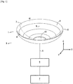
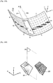
- the object of the invention relates to a therapy device I in the general sense comprising a therapy probe 1 suitable for carrying out the treatment of tissues of a living being by means of high intensity focused ultrasound (HIFU).
- the therapy probe 1 comprises in particular a transducer 2 comprising several ultrasonic emitters 3 such as for example piezoelectric elements, thus defining a face 4 for emitting focused ultrasonic waves.
- These ultrasonic transmitters 3 are connected by means of coaxial cables 5 via an amplifier stage 6 to a control circuit 7 delivering signals to activate the ultrasonic transmitters 3.
- the control circuit 7 is not described more precisely because its realization is part of the technical knowledge of a person skilled in the art.
- This control circuit 7 thus conventionally comprises a controlled signal generator which is connected to the ultrasonic emitters via the amplifier stage 6.
- each ultrasonic emitter 3 is connected to its own signal generator.
- the signal generator of the control circuit 7 activates the ultrasonic emitters 3 distributed in segments and more precisely in segments of curves or straight lines to define a surface 8 for creating a pressure field of focused ultrasonic waves.
- the signal generator forming part of the control circuit 7 is driven to deliver signals to activate the ultrasonic emitters 3 of the transducer 2, with a law of delays or of phases in order to produce the creation surface. 8 of a pressure field of focused ultrasonic waves, this creation surface 8 being considered as a virtual creation surface distinct from the emission face 4 of the transducer ( Fig. 2 , 9A , 10A ).
- the surface 8 for creating a pressure field of focused ultrasonic waves corresponds to the face 4 of the transducer.
- the creation surface 8 of a pressure field of focused ultrasonic waves corresponds either to the physical transducer or more precisely to the face 4 of the transducer 2 or to a virtual creation surface 8 by applying phases to it. the transducer control channels 2.
- Phase not M arctan Im P not m D P not m
- Another calculation method consists in establishing the path difference, for each element n, emitting between the natural focal point and the desired focal point.
- Another calculation method consists of defining a virtual ultrasonic emitter, of different geometry but also cut into N elements, then making the center of the first element of the real emitter coincide in space with the center of the first element of the emitter. virtual.
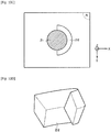
- the shape of the creation surface 8 changes in particular as a function of the applications of the therapy device. It therefore appears advantageous to have a probe with a face 4 of determined shape that is easy to produce by a person skilled in the art ( Fig. 1 for example) and generate from this face 4, creation surfaces 8 which have complex shapes to achieve and different from the shape of face 4 (as illustrated in Fig. 2 for example). However, it can be envisioned to produce a transducer 2 with a face 4 whose shape corresponds to a surface 8 for creating a pressure field of focused ultrasonic waves, such as that illustrated in FIG. Fig. 2 for example.
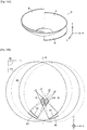
- the creation surface 8 presents according to a first variant embodiment ( Fig. 1 , 2, 3 , 7A-7C , 8A-8C , 9A-9D , 10A-10F , 11A to 11E ), a form of revolution around an axis of symmetry S or, according to a second variant embodiment ( Fig. 12 , 12A-12C , 13A-13D ), a pseudo-cylindrical, tubular or composed of two cylinder portions having a plane of symmetry A1.
- the Fig. 4 , 5 , 6 and 6A are profile views making it possible to illustrate the creation surface 8 according to the first variant embodiment and according to the second variant embodiment.
- the axis of symmetry S which is established in the vertical direction Z corresponds to the axis of symmetry or to the acoustic axis of the face 4 of the transducer produced in the form of a face of revolution.
- the plane of symmetry A1 is established in the plane defined by the vertical direction Z and the transverse direction Y, this plane of symmetry being perpendicular to a plane of profile Pp defined by the axes X, Z of a reference frame X, Y, Z.
- This plane of symmetry A1 is the plane of symmetry or the acoustic plane of face 4 of the transducer.
- the creation surface 8 is divided into at least N sectors 8 1 , 8 2 , ..., in a radial cutout to the acoustic axis S and containing l 'acoustic axis S or extending in mirror position with respect to the acoustic plane A1.
- the sectors are sectors radial with respect to the acoustic axis S comprising for each of them, ultrasonic emitters 3 distributed in rings, while in the second variant embodiment, the sectors are sectors in mirror position relative to the acoustic plane A1 comprising ultrasonic emitters 3 distributed in linear segments.
- the N radial sectors are advantageously between 2 and 8 and preferably equal to 2 ( Fig. 2 ) whereas in the second variant embodiment, the N sectors perpendicular to the acoustic plane A1 are between 2 and 32 ( Fig. 12 and 13A ).
- the ultrasonic emitters 3 of the transducer are limited in number, making it possible to reduce the cost of such a transducer.
- each sector can comprise 32 ultrasonic emitters 3.
- only the term sector will be used in the remainder of the description.
- the creation surface 8 is divided into N sectors 8 1 , 8 2 , ..., to focus the ultrasonic waves on focal areas Zc 1 , Zc 2 , ... respectively being established in focal planes Pf 1 , Pf 2 , ...,.
- the Fig. 2 to 6 , 9A , 10A , 12 illustrate a preferred embodiment in which the creation surface 8 is divided into two sectors 8 1 , 8 2 .
- the Fig. 1 shows another exemplary embodiment for which the emission surface 4 is advantageously divided into two sectors 4 1 , 4 2 , making it possible to create a creation surface 8 divided into two symmetrically opposed sectors.
- the Fig. 7A illustrates another exemplary embodiment for which the emission surface 4 is advantageously divided into four sectors 4 1 , 4 2 , 4 3 , 4 4 , thus making it possible to create a creation surface 8 itself divisible up to four sectors 8 1 , 8 2 , 8 3 , 8 4 .
- the emission surface 4 is divided into four sectors in order to create a creation surface 8 divided into two sectors according to two orthogonal planes ( Fig. 7B and 7C ).
- each sector 8 1 , 8 2 , ... of this creation surface 8 present in a profile plane Pp defined by the X, Z axes of an X, Y, Z coordinate system, a concave curve segment S1, S2 , ... of finite length.
- the concave curve segments S1, S2 of the sectors 8 1 , 8 2 are delimited by end points respectively 8a 1 , 8b 1 and 8a 2 , 8b 2 .
- the two concave curve segments S1, S2, ... are located on either side of the plane of symmetry A1 or of the axis of symmetry S.
- the segments of concave curves S1, S2, ... are asymmetrical with respect to an axis of symmetry S of the transducer 2 as in the first variant embodiment of the creation surface 8 with a shape of revolution around the axis of symmetry ( Fig. 1 , 2, 3 , 7A-7C , 8A-8C , 9A-9D , 10A-10F , 11A to 11E ) or with respect to a plane of symmetry A1 of the transducer according to the second variant embodiment of the creation surface 8 with a pseudo-cylindrical shape ( Fig. 12 , 12A-12C , 13A-13D ).
- each segment of concave curve S1, S2, ... has a center of curvature respectively C 1 , C 2 , ... corresponding to an ultrasonic focusing zone Zc1, Zc2, ...
- the segments of concave curve S1, S2, ... of the sectors are asymmetrical with respect to the plane of symmetry A1 or to the axis of symmetry S.
- the distance from the center of curvature c 1 of the first sector 8 1 with respect to the axis of symmetry S or the plane of symmetry A1 is greater than the distance from the center of curvature c 2 of the second sector 8 2 with respect to the axis of symmetry S or the plane of symmetry A1, these distances being taken in the direction X perpendicular to the axis of symmetry S or to the plane of symmetry A1. It should be noted that in the example illustrated in Fig.
- the centers of curvature c 1 , c 2 are located at the same depth along the vertical direction Z (or axis of symmetry S), that is to say that they are located along the same straight line perpendicular to the axis of symmetry S or to the plane of symmetry A1.
- the centers of curvature c 1 , c 2 are located along focal planes respectively Pf 1 , Pf 2 which coincide.
- the Fig. 5 illustrates another exemplary embodiment for which the distance of the center of curvature c 1 with respect to the axis of symmetry S or the plane of symmetry A1 is different from the distance of the center of curvature c 2 with respect to the axis of symmetry S or of the plane of symmetry A1 but also the depth along the axis of symmetry S, of the center of curvature c 1 is different from the depth along the axis of symmetry S, of the center of curvature c 2 .
- the distance of the center of curvature c 1 with respect to the axis of symmetry S or the plane of symmetry A1 is different from the distance of the center of curvature c 2 with respect to the axis of symmetry S or of the plane of symmetry A1 but also the depth along the axis of symmetry S, of the center of curvature c 1 is different from the depth along the axis of symmetry S, of the center of curvature c 2 .
- the focal plane Pf 2 containing the center of curvature c 2 is along the axis of symmetry S, further from the transducer than the focal plane Pf 1 containing the center of curvature c 1 .
- the centers of curvature c1, c2 are located along focal planes respectively Pf1, Pf2 which are distinct.
- the centers of curvature c 1 , c 2 are also considered as asymmetrical in the case where the depths along the axis of symmetry S are different while the distances of the centers of curvature c 1 , c 2 with respect to the axis of symmetry S or the plane of symmetry A1 are identical.
- the centers of curvature c1, c2 are located along focal planes respectively Pf1, Pf2 which are distinct.
- Each segment of concave curve S1, S2, ... of the sectors has a specific axis respectively a 1 , a 2 , ... passing through the center of curvature c 1 , c 2 , ... of said concave curve segment and the midpoint of said concave curve segment S1, S2, ....
- the specific axes a 1 , a 2 , ... of the concave curve segments intersect to create a focal zone of overlap Zr which is offset with respect to the plane of symmetry A1 or with respect to the axis of symmetry S.
- This focal zone of overlap Zr corresponds to a focal zone of overlap of the ultrasonic beams coming from the sectors 8 1 , 8 2 , ... of the creation surface 8.
- the focal zone of overlap Zr presents in the profile plane Pp, a section with four sides in the form of a parallelogram, delimited by the beams coming from the end points 8a 1 , 8b 1 and 8a 2 , 8b 2 of the concave curve segments respectively S1, S2.
- This focal zone of overlap Zr of the ultrasonic waves is advantageously used to create a bulky biological lesion.
- the geometry of the lesions produced is controlled by the combination of the focal zones Zc1, Zc2, ... and of the focal zone of overlap Zr.
- the energy deposition zone corresponds to the focal overlap zone Zr, independently of the energy possibly deposited in the other focal zones.
- This focal zone of overlap Zr is offset in the sense that the proper axes a 1 , a 2 , ... intersect at a common point of intersection I which is located outside the plane of symmetry A 1 or outside l axis of symmetry S.
- the specific axes a 1 , a 2 , ... intersect either at a depth located between the focal zones Zc 1 , Zc 2 , ... and the creation surface 8 as illustrated in Fig. 3 to 6 and 12 , that is beyond the focal zones Zc 1 , Zc 2 , ... as illustrated in Fig. 6A .
- the beams coming from sectors 8 1 , 8 2 , ... cross so that the focal overlap zone Zr is located in the vertical direction Z, at a distance from the focal planes Pf 1 , Pf 2 , ....
- the curve segments S1, S2, ... extend in the profile plane Pp, on either side of the axis of symmetry S or of the plane of symmetry A1, being disjoint to allow the positioning of the focal overlap zone Zr at a distance from the creation surface 8.
- the so-called internal end points 8a 1 , 8a 2 of the curve segments are spaced from the axis of symmetry S or from the plane of symmetry A1.
- the creation surface 8 and consequently, the face 4 has an opening 10 centered on the axis of symmetry S or on the plane of symmetry A1.
- the so-called internal end points 8a 1 , 8a 2 of the curve segments located in the profile plane Pp are spaced from each other by an internal distance Di taken along the X axis of between 10 mm and 120 mm.
- Di taken along the X axis of between 10 mm and 120 mm.
- the choice of the distance between these end points leads to a modification of the position of the focal overlap zone Zr with respect to the creation surface 8 ( Fig. 3 , 4 , 5 , 8B , 9B , 10B ) or a modification of the shape of the focal overlap zone Zr and of its spread along the Z axis ( Fig. 6A ) depending on the configuration considered.
- this opening 10 serves as a housing for an ultrasound imaging probe.
- the so-called external end points 8b 1 , 8b 2 of the sectors are separated by an external distance Ds making it possible to locate the focal zone of overlap Zr at a distance from the focal planes.
- the focal area of overlap Zr does not touch the focal plane Pf 1 , Pf 2 , ....
- the focal area of overlap Zr and the focal areas Zc 1 , Zc 2 , ... are distinct or separate from each other.
- the sectors 8 1 , 8 2 , ... of the creation surface 8 are generated either, according to the first variant embodiment, by the rotation of 2 ⁇ / N of the concave curve segments S1, S2, ... around the axis of symmetry S with N, the number of sectors, i.e., according to the second variant embodiment, by the translation of the segments of curve S1, S2, ... in a direction Y perpendicular to the profile plane Pp containing said segments of curve S1, S2, ....
- the sectors 8 1 , 8 2 , ... extend along angular ranges or lengths of substantially identical values.
- each sector 8 1 , 8 2 extends according to an angular range of 180 ° ( Fig. 2 ).
- the sectors 8 1 , 8 2 , ..., located in a mirror position along the axis of symmetry S or the plane of symmetry A1 create zones of energy deposition with profiles corresponding to the focal zones of overlap Zr and zones focal lengths Zc.
- the sectors of the creation surface 8 are generated by the rotation of the concave curve segments around the axis of symmetry S, then the focal zones Zc 1 , Zc 2 , ... have shapes in a portion of circles.
- the focal zones Zc 1 and Zc 2 are semicircles extending according to an angular range of 180 ° ( Fig. 3 ).
- the focal zones Zc 1 , Zc 2 ... extend along linear segments located in the focal planes Pf1, Pf2, ..., parallel to the direction Y ( Fig. 12 ).
- the focal zones Zc 1 and Zc 2 extend along two linear segments located in the focal planes Pf1, Pf2, parallel to the direction Y ( Fig. 12 ).
- the creation surface 8 of a pressure field of focused ultrasonic waves is obtained or produced using a transducer whose face 4 is adapted to obtain the characteristics of the creation surface 8 described above.
- the creation surface 8 comes from a face 4 defined by the transducer elements, of advantageously toric geometry generated by the rotation of concave curve segments around the axis of symmetry S so that the concave curve segments follow non-coincident arcs of circles which intersect so that the focal zones Zc 1 , Zc 2 , ... have the shape of portions of a circle.
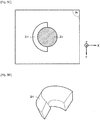
- This face 4 of the transducer corresponds as illustrated to Fig. 8A , to a cutout of a portion of the envelope of a crossed torus, along two planes perpendicular to the axis of symmetry S.
- the surface of the creation surface 8 comes from a face 4 defined by the transducer elements, of cylindrical geometry generated by the translation along a limited length, of two curve segments in a direction Y perpendicular to the profile plane Pp containing said curve segments so that the focal zones Zc1, Zc2 ... have a linear shape.
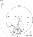
- the Fig. 8A gives a preferred embodiment of the face 4 of the transducer 2 defined by segments of concave curve based on a crossed toric geometry.
- the emission face 4 comprises, in the profile plane Pp, two segments of concave curves S ' 1 , S' 2 which follow the arcs respectively of a first circle E'1 having a center c ' 1 and of a second circle E ' 2 having another center c' 2 different from the center c ' 1 of the first circle E'1.
- the first and second circles E'1, E'2 do not coincide but intersect with each other.
- One of the two concave curve segments S ' 1 (to the right on the Fig. 8B ), follows the arc of the first circle E'1, this arc of the first circle E'1 being located inside the second circle E'2.
- the other concave segment S ' 2 (to the left on the Fig. 8B ) follows the arc of the second circle E'2, this arc of the second circle E'2 being located inside the first circle E'1.
- This emission face 4 has, in the profile plane Pp, two segments of concave curve S ' 1 , S' 2 of finite length, symmetrical with respect to the axis of symmetry S.
- each concave segment S ' 1 , S' 2 of the emission face 4 focuses the ultrasonic waves at the center c ' 1 , c' 2 of the circle in zones of ultrasonic focusing respectively Zc'1, Zc ' 2 located beyond the axis of symmetry S with respect to the corresponding emission face 4 S ' 1 , S' 2 , these ultrasonic focusing zones Zc'1, Zc'2 being established in a focal plane Pf '.
- the specific axes of the concave curve segments S ′ 1 , S ′ 2 intersect the axis of symmetry S at a common point of intersection I ′ situated on this axis of symmetry S for the first variant embodiment.
- This common point of intersection of the specific axes is located between the emission face 4 and the focal zones Zc'1, Zc'2 or beyond the focal plane Pf '.
- the beams of the emission face 4 cross to form the overlap zone Z'r of the ultrasonic beams which is symmetrical with respect to the axis of symmetry S.
- This focal zone of overlap Z'r of the ultrasonic beams, said natural is centered on the axis of symmetry S.
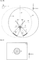
- the emission face 4 is obtained by the rotation around the axis of symmetry S, of a concave curve segment illustrated by S ′ 1 and S ' 2 in section view, the center of curvature of which is located on the side opposite to said segment of curve with respect to the axis of symmetry S.
- the Fig. 8C illustrates in the XY plane, the shape of the natural focal zone of overlap Z'r obtained by such a revolution transducer. It should be remembered that in the case of a toric-shaped transducer, the transducer also deposits pressure in a focal plane in the form of a circle represented by the focal zones Zc'1, Zc'2 ( Fig. 8B ).
- the emission face 4 is a surface of revolution.
- This emission face 4 comprises, for example, a series of ultrasonic transducer elements 3 mounted concentrically with respect to each other and with respect to the axis of symmetry S.
- the emitting face 4 is truncated symmetrically with respect to the axis of symmetry S so that the transducer is limited to a portion of a crossed torus having a width of, for example, between 5 and 250 mm.
- the transducer 2 comprises a series of ultrasonic transducer elements 3 mounted concentrically with respect to each other and with respect to the axis of symmetry S so that they are distributed in the form of ring-shaped segments.
- the emission face 4 is obtained by the implementation, according to the principle described above, of two segments of concave curve S ' 1 , S' 2 of finite length, symmetrical with respect to the plane of symmetry A1 and the translation of these two segments of concave curve S ' 1 , S' 2 in the direction Y perpendicular to the profile plane Pp containing said concave curve segments.
- each part of the emission face 4 focuses before, after or on the plane of symmetry A 1 , according to a linear segment extending in the focal plane, parallel to the direction Y.
- the specific axes of the concave curve segments S ' 1 , S' 2 intersect the plane of symmetry A1 at an axis of intersection I "included in the plane of symmetry A1 ( Fig. 12A ).
- the beams of the emission face 4 intersect to form the overlap zone Z'r of the ultrasonic beams which is symmetrical with respect to the plane. of symmetry A1.
- This focal zone of overlap Z'r of the ultrasound beams, called natural, is centered on the plane of symmetry A1.
- the creation surface 8 in accordance with the invention is created, the characteristics of which have been described above.
- the creation surface 8 is divided into two sectors 8 1 , 8 2 by way of preferred embodiment but the object of the invention can be implemented for a creation surface 8 comprising a higher number of sectors.
- the transducer 2 corresponds to the physical or real transducer held in the hands of the user and that the creation surface 8 is formed by two virtual half-transducers simulated by applying phases to each of the paths of the physical transducer after have subdivided the two sectors into several emitting elements.
- the determination of these phases then consists simply in calculating, for each emitting element, the ultrasound propagation time between the transducer 2 and the creation surface 8.
- two parts of transducers are created virtually making it possible to move the focusing elements without moving the geometric elements specific to the transducer physical like the acoustic axis or the axis of symmetry.
- the signal generator forming part of the control circuit 7 is driven to deliver signals to activate the ultrasonic transmitters 3 distributed in rings, with a law of delays or of phases in order to achieve the creation surface 8 of a pressure field of focused ultrasonic waves.
- Fig. 9A - 9D and 10A - 10F illustrate the operation of the ultrasonic transmitters 3 of the transducer illustrated in Fig. 8A - 8C , to produce the creation surface 8 of the type of the first variant embodiment comprising two sectors 8 1 , 8 2 .
- the signal generator forming part of the control circuit 7 is driven to deliver signals for, in an exposure phase, activate the ultrasonic emitters 3 forming part of a sector 4 1 and of the symmetrically opposite sector 4 2 with respect to the axis of symmetry S, to create the corresponding energy deposition zone.
- the ultrasonic emitters 3 of the two sectors 4 1 , 4 2 are activated to obtain the creation surface 8 of the pressure field of focused ultrasonic waves so that the latter forms two emission faces, each obtained by the rotation around the axis of symmetry S, of different concave curve segments s 1 and s 2 .
- the centers of curvature c 1 , c 2 can be located independently for each sector 8 1 , 8 2 on the side opposite or not to said curve segment with respect to the axis of symmetry, thus making it possible to create a deposit zone of energy Zr1 offset with respect to the axis of revolution, as illustrated on the Fig. 9B and 9C .
- the activation of the ultrasonic emitters 3 forming part of the sector 8 1 and of the symmetrically opposed sector 8 2 makes it possible to create an energy deposition zone and in particular an arcuate energy deposition zone Zr 1 with a corresponding profile. to the focal area of overlap. This principle applies to all the sectors making up the transducer, making it possible to refine the shape of the zone in which the pressure is deposited.
- a second phase of exposure illustrated more precisely to Fig. 10A - 10D
- the ultrasonic emitters 3 of the two sectors 4 1 , 4 2 are activated to create with respect to the arcuate energy deposition zone Zr 1 illustrated in Fig. 9D , an arcuate zone of energy deposition Zr 2 , symmetrical with a profile corresponding to the focal zone of overlap.
- the control circuit will again activate the entire surface of the transducer by inverting the phases applied between the sectors with respect to the principle described above.
- the signal generator forming part of the control circuit 7 is driven to deliver signals for, in successive exposure phases, activating the ultrasonic emitters forming part of each of the sectors and of each sector symmetrically opposed with respect to to the axis of symmetry, so as to create, for each pair of sectors, the corresponding energy deposition zone.
- the signal generator forming part of the control circuit 7 is driven to deliver signals for, in successive exposure phases, activating the ultrasonic emitters forming part of each of the sectors and of each sector symmetrically opposed with respect to to the axis of symmetry, so as to create, for each pair of sectors, the corresponding energy deposition zone.
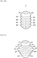
- Fig. 10E - 10F it is possible by two successive ultrasound exposures to create a coagulation ring.
- the coagulation crown has a constant profile or width.
- the profile or the width of the arcuate energy deposition zones as well as the height in the Z direction as well as their positions with respect to the axis of symmetry S.
- the signal generator forming part of the control circuit 7 is driven to deliver signals for activating the ultrasonic emitters in successive exposure phases for each of which the centers of curvature c 1 , c 2 , ... are located at different distances from the plane of symmetry A 1 or from the axis of symmetry S and / or at different depths along the vertical axis Z so as to obtain offset energy deposition zones.
- the signal generator forming part of the control circuit 7 is driven to deliver signals for activating the ultrasonic emitters in successive exposure phases for which the centers of curvature c 1 , c 2 , ... are located at different distances from the plane of symmetry A1 or from the axis of symmetry S and / or at different depths along the vertical axis Z so as to obtain, for these successive exposure phases, offset zones of energy deposition, of different positions with the same or different sizes.
- the ultrasonic emitters of all of the two sectors 8 1 , 8 2 have undergone two activation phases for which the phases have been calculated so that the focal areas of overlap Zr1 and Zr2 are symmetrical with respect to the axis of symmetry S. This is reflected at the level of the creation surface 8 by the transformation of the concave curve segment S 1 into S 2 and of the concave curve segment S 2 into S 1 during the second activation cycle.
- the Fig. 11A illustrates an exemplary embodiment in which for an exposure cycle the ultrasonic emitters of all of the two sectors 8 1 , 8 2 have undergone two activation phases for which the phases have been calculated so that the focal zones of overlap Zr1 and Zr2 are asymmetrical with respect to the axis of symmetry S.
- the activation phases are carried out with centers of curvature c 1 , c 2 , positioned in a suitable manner to obtain focal areas of overlap Zr1 and Zr2 asymmetric.
- the Fig. 11B illustrates an exemplary embodiment for which the signal generator forming part of the control circuit 7 is controlled so that the ultrasonic emitters of all of the two sectors 8 1 , 8 2 undergo two activation phases for which the phases have been calculated so that the focal zones of overlap Zr1 and Zr2 are symmetrical with respect to the axis of symmetry S.
- These two phases of activation form an exposure cycle which is repeated for different depths along the vertical axis Z in order to obtain superimposed energy deposition crowns forming a cylinder having an identical width and height from one exposure cycle to another.
- the Fig. 11C illustrates another exemplary embodiment for which the signal generator forming part of the control circuit 7 is driven to deliver signals to activate the ultrasonic emitters 3 so that the focal areas of overlap Zr are located at different distances and at depths different along the vertical axis Z so as to obtain overlapping focal areas of varying widths and / or heights.
- the energy deposit volume is hollow, that is to say not in contact with the axis of symmetry S.
- the signal generator forming part of the control circuit can be controlled. in order, in at least one complementary exposure phase, to deliver signals to activate the ultrasonic transmitters so as to ensure the focusing of the ultrasonic waves in focal zones and to obtain a focal zone of overlap Z'r centered with respect to the plane of symmetry A1 or to the axis of symmetry S and located at a distance from the focal planes between the focal zones and the emitting face or beyond the focal zones.
- a complementary so-called natural exposure phase can be carried out according to the principle described in Fig. 8A and 8B , for one or each exposure phase so as to complete the energy deposition volume.
- this additional exposure phase can be implemented for one and / or the other of the embodiments described above. So the Fig. 11D illustrates the implementation of a complementary exposure phase for the variant illustrated in Fig. 11B .
- Fig. 11E illustrates in top view, a focal zone of natural overlap Z'r centered with respect to the axis of symmetry S surrounded by a focusing ring K produced in two successive ultrasound exposures as explained previously. It should be noted that this Figure illustrates the realization around the focusing ring K, of an additional focusing ring produced in four successive ultrasound exposures implemented by a creation surface 8 divided into four sectors, to create four focal zones overlap Zr1 to Zr4.
- the first focal zone has a double linear shape.
- the conditions for implementing the invention described in relation to Fig. 10A-10F , 11A-11E for the first variant embodiment apply in a similar manner for this creation surface 8 of pseudo-cylindrical shape.
- the ultrasonic emitters 3 are cut out parallel to the plane of symmetry A1 and are activated with a law of delays or of phases in order to produce the creation surface 8.
- the ultrasonic emitters are distributed according to at least two sectors and according to the example shown in Fig. 12 , two sectors 8 1 , 8 2 arranged symmetrically with respect to the plane of symmetry A1.
- the signal generator forming part of the control circuit is driven to deliver signals for, in an exposure phase, to activate the transmitters.
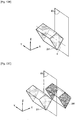
- ultrasound forming part of a sector located on one side of the plane of symmetry A1 and of the symmetrically opposite sector to create the corresponding energy deposition zone. It is thus possible to produce an energy deposit volume Zr1 (or a focal overlap zone Zr1) on one side of the plane of symmetry A1 and at a distance from this plane of symmetry ( Fig. 12B ).
- an energy deposition volume Zr2 or a focal zone of overlap Zr2 on the other side of the plane of symmetry A1 and at a distance from this plane of symmetry A1 ( Fig. 12C ).
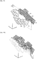
- the ultrasonic emitters are distributed along several sectors perpendicular to the plane of symmetry A1 and arranged facing each other along the plane of symmetry A1.
- nine sectors are located on each side of the plane of symmetry A1, with each sector on one side being opposite a sector on the other side.
- the signal generator forming part of the control circuit is driven to deliver signals for, in an exposure phase, to activate the ultrasonic emitters forming part of a sector and of the opposite sector, with a law of delays or of phases for create the corresponding energy deposition zone on one side of the plane of symmetry ( Fig. 13A ).
- the ultrasonic emitters of the opposite sectors are capable of creating volumes of energy deposition on either side of the plane of symmetry A1.
- the Fig. 13B illustrates the production of two energy deposit volumes located on either side of the plane of symmetry A1.
- the thickness of the energy deposition volume corresponds to the width of a sector of the transducer.
- each volume of energy deposit can vary in shape, size and location by playing in particular on the position of the centers of curvature.
- the successive activation of the different sectors of the transducer makes it possible to produce a hollow energy deposition volume of variable thickness ( Fig. 13C ).
- This solution finds particularly advantageous applications for treating target areas extending along a non-rectilinear segment T, for example allowing the treatment of tumors along arteries or veins, along the digestive tract, along the bones, along the Wirsung duct into the pancreas, urethra or bile duct ( Fig. 13D ).
- the object of the invention makes it possible to achieve a displacement of the focal zone in depth (along the acoustic axis and a displacement in a plane parallel to the transducer (perpendicular to the acoustic axis) while by reducing the number of emitters
- the object of the invention aims to directly create a volume (portion of crown) obtained by calculating a “virtual” creation surface or virtual transducer and moving this volume without having to resort to a large number of transmitters. transducer.
Landscapes
- Engineering & Computer Science (AREA)
- Health & Medical Sciences (AREA)
- Life Sciences & Earth Sciences (AREA)
- Biomedical Technology (AREA)
- Nuclear Medicine, Radiotherapy & Molecular Imaging (AREA)
- Radiology & Medical Imaging (AREA)
- Animal Behavior & Ethology (AREA)
- General Health & Medical Sciences (AREA)
- Public Health (AREA)
- Veterinary Medicine (AREA)
- Multimedia (AREA)
- Mechanical Engineering (AREA)
- Acoustics & Sound (AREA)
- Physics & Mathematics (AREA)
- Surgical Instruments (AREA)
Applications Claiming Priority (1)
| Application Number | Priority Date | Filing Date | Title |
|---|---|---|---|
| FR2003282A FR3108854B1 (fr) | 2020-04-02 | 2020-04-02 | Appareil de thérapie pour le traitement de tissus par l’émission d’ondes ultrasonores focalisées croisées déportées |
Publications (1)
| Publication Number | Publication Date |
|---|---|
| EP3888748A1 true EP3888748A1 (fr) | 2021-10-06 |
Family
ID=72644288
Family Applications (1)
| Application Number | Title | Priority Date | Filing Date |
|---|---|---|---|
| EP21165904.0A Pending EP3888748A1 (fr) | 2020-04-02 | 2021-03-30 | Appareil de therapie pour le traitement de tissus par l'emission d'ondes ultrasonores focalisees croisees deportees |
Country Status (5)
| Country | Link |
|---|---|
| US (1) | US11801400B2 (enExample) |
| EP (1) | EP3888748A1 (enExample) |
| JP (1) | JP7671446B2 (enExample) |
| CN (1) | CN113491847A (enExample) |
| FR (1) | FR3108854B1 (enExample) |
Cited By (1)
| Publication number | Priority date | Publication date | Assignee | Title |
|---|---|---|---|---|
| WO2022180198A1 (en) * | 2021-02-26 | 2022-09-01 | Institut National De La Sante Et De La Recherche Medicale (Inserm) | Therapeutic ultrasonic transducers for the emission of focused ultrasound waves |
Families Citing this family (1)
| Publication number | Priority date | Publication date | Assignee | Title |
|---|---|---|---|---|
| CN119344865B (zh) * | 2024-12-24 | 2025-10-21 | 北京小超科技有限公司 | 一种无创能量聚焦手术的治疗路径规划方法及系统 |
Citations (10)
| Publication number | Priority date | Publication date | Assignee | Title |
|---|---|---|---|---|
| EP0214782A2 (en) | 1985-08-16 | 1987-03-18 | Hitachi, Ltd. | Ultrasonic irradiation system |
| EP0661029A1 (en) | 1993-12-28 | 1995-07-05 | Kabushiki Kaisha Toshiba | Method and apparatus for ultrasonic medical treatment with optimum ultrasonic irradiation control |
| US5522869A (en) | 1994-05-17 | 1996-06-04 | Burdette; Everette C. | Ultrasound device for use in a thermotherapy apparatus |
| US6506171B1 (en) * | 2000-07-27 | 2003-01-14 | Insightec-Txsonics, Ltd | System and methods for controlling distribution of acoustic energy around a focal point using a focused ultrasound system |
| EP2035091A1 (fr) | 2006-07-05 | 2009-03-18 | Edap S.A. | Appareil de therapie a fonctionnement sequentiel |
| WO2011024074A2 (en) | 2009-08-26 | 2011-03-03 | Insightec Ltd. | Asymmetric phased-array ultrasound transducer |
| WO2011092683A1 (en) | 2010-02-01 | 2011-08-04 | Livesonics Ltd. | Non-invasive ultrasound treatment of subcostal lesions |
| EP2691154A1 (fr) | 2011-03-29 | 2014-02-05 | EDAP TMS France | Sonde de therapie pour le traitement de tissus par l'intermediaire d'ondes ultrasonores focalisees croisees |
| EP2865420A1 (fr) * | 2013-10-23 | 2015-04-29 | EDAP TMS France | Appareil de génération d'ondes ultrasonores focalisées à temps de traitement réduit |
| WO2016144931A1 (en) | 2015-03-09 | 2016-09-15 | The Research Foundation For The State University Of New York | Systems and methods for promoting cellular activities for tissue maintenance, repair, and regeneration |
Family Cites Families (3)
| Publication number | Priority date | Publication date | Assignee | Title |
|---|---|---|---|---|
| US20130051178A1 (en) * | 2010-05-03 | 2013-02-28 | Wavomed Ltd. | Resonantly amplified shear waves |
| CN109414243B (zh) * | 2016-03-11 | 2022-03-29 | 索邦大学 | 用于脊髓和脊神经治疗的外部超声波生成治疗装置、包括该装置的设备和实施该装置的方法 |
| EP3568079B1 (en) * | 2017-01-11 | 2024-05-22 | Institut National de la Santé et de la Recherche Médicale (INSERM) | Method and apparatus for imaging in real time the propagation of a mechanical wave in an acoustically propagative material |
-
2020
- 2020-04-02 FR FR2003282A patent/FR3108854B1/fr active Active
-
2021
- 2021-03-30 EP EP21165904.0A patent/EP3888748A1/fr active Pending
- 2021-04-01 JP JP2021063075A patent/JP7671446B2/ja active Active
- 2021-04-01 US US17/220,075 patent/US11801400B2/en active Active
- 2021-04-02 CN CN202110362068.4A patent/CN113491847A/zh active Pending
Patent Citations (10)
| Publication number | Priority date | Publication date | Assignee | Title |
|---|---|---|---|---|
| EP0214782A2 (en) | 1985-08-16 | 1987-03-18 | Hitachi, Ltd. | Ultrasonic irradiation system |
| EP0661029A1 (en) | 1993-12-28 | 1995-07-05 | Kabushiki Kaisha Toshiba | Method and apparatus for ultrasonic medical treatment with optimum ultrasonic irradiation control |
| US5522869A (en) | 1994-05-17 | 1996-06-04 | Burdette; Everette C. | Ultrasound device for use in a thermotherapy apparatus |
| US6506171B1 (en) * | 2000-07-27 | 2003-01-14 | Insightec-Txsonics, Ltd | System and methods for controlling distribution of acoustic energy around a focal point using a focused ultrasound system |
| EP2035091A1 (fr) | 2006-07-05 | 2009-03-18 | Edap S.A. | Appareil de therapie a fonctionnement sequentiel |
| WO2011024074A2 (en) | 2009-08-26 | 2011-03-03 | Insightec Ltd. | Asymmetric phased-array ultrasound transducer |
| WO2011092683A1 (en) | 2010-02-01 | 2011-08-04 | Livesonics Ltd. | Non-invasive ultrasound treatment of subcostal lesions |
| EP2691154A1 (fr) | 2011-03-29 | 2014-02-05 | EDAP TMS France | Sonde de therapie pour le traitement de tissus par l'intermediaire d'ondes ultrasonores focalisees croisees |
| EP2865420A1 (fr) * | 2013-10-23 | 2015-04-29 | EDAP TMS France | Appareil de génération d'ondes ultrasonores focalisées à temps de traitement réduit |
| WO2016144931A1 (en) | 2015-03-09 | 2016-09-15 | The Research Foundation For The State University Of New York | Systems and methods for promoting cellular activities for tissue maintenance, repair, and regeneration |
Non-Patent Citations (3)
| Title |
|---|
| AUBRY, J.F. ET AL.: "The road to clinical use of high-intensity focused ultrasound for liver cancer : technical and clinical consensus", J THER ULTRASOUND, vol. 1, 2013, pages 13, XP021162611, DOI: 10.1186/2050-5736-1-13 |
| KENNEDY, J.E.: "High-intensity focused ultrasound in the treatment of solid tumours", NAT REV CANCER, vol. 5, no. 4, 2005, pages 321 - 7 |
| VINCENOT, J. ET AL.: "Electronic beam steering used with a toroidal HIFU transducer substantially increases the coagulated volume", ULTRASOUND MED BIOL, vol. 39, no. 7, 2013, pages 1241 - 54 |
Cited By (1)
| Publication number | Priority date | Publication date | Assignee | Title |
|---|---|---|---|---|
| WO2022180198A1 (en) * | 2021-02-26 | 2022-09-01 | Institut National De La Sante Et De La Recherche Medicale (Inserm) | Therapeutic ultrasonic transducers for the emission of focused ultrasound waves |
Also Published As
| Publication number | Publication date |
|---|---|
| FR3108854A1 (fr) | 2021-10-08 |
| FR3108854B1 (fr) | 2022-09-16 |
| JP2021159775A (ja) | 2021-10-11 |
| US20210308491A1 (en) | 2021-10-07 |
| US11801400B2 (en) | 2023-10-31 |
| CN113491847A (zh) | 2021-10-12 |
| JP7671446B2 (ja) | 2025-05-02 |
Similar Documents
| Publication | Publication Date | Title |
|---|---|---|
| EP2691154B1 (fr) | Sonde de therapie pour le traitement de tissus par l'intermediaire d'ondes ultrasonores focalisees croisees | |
| EP2035091B1 (fr) | Appareil de therapie a fonctionnement sequentiel | |
| EP2691948B1 (fr) | Procede et appareil de generation d'ondes ultrasonores focalisees a modulation de surface | |
| EP2575967B1 (fr) | Transducteur d'ultrasons à usage médical | |
| EP0068961A2 (fr) | Dispositif d'échauffement localisé de tissus biologiques | |
| EP0307300A1 (fr) | Dispositif piézoélectrique à ondes négatives réduites, et utilisation de ce dispositif pour la lithotritie extra corporelle ou pour la destruction de tissus particuliers | |
| FR2700939A1 (fr) | Appareil de thérapie pour la localisation et le traitement, à l'aide d'ondes acoustiques, d'une zone située dans le corps d'un être vivant. | |
| FR2532851A1 (fr) | Applicateur pour hyperthermie par ultrasons avec coherence variable par focalisation en spirales multiples | |
| EP0664996A1 (fr) | Procédé de commande d'un appareil de traitement par hyperthermie à l'aide d'ultrasons | |
| EP3888748A1 (fr) | Appareil de therapie pour le traitement de tissus par l'emission d'ondes ultrasonores focalisees croisees deportees | |
| EP1909675B1 (fr) | Tete d'imagerie et de traitement d'organes d'etres vivants | |
| WO1999058196A1 (fr) | Reglage de frequence dans un appareil de traitement par ultrasons focalises de haute intensite | |
| EP3099240A1 (fr) | Procede et dispositif ultrasonore de caracterisation des milieux mous anisotropes, et ensemble de sonde ultrasonore pour un tel dispositif de caracterisation | |
| FR2631707A1 (fr) | Echographe ultrasonore a coherence de phase controlable | |
| EP2069821B1 (fr) | Sonde d'imagerie ultrasonore pour imager une modification transitoire d'un milieu | |
| FR2886534A1 (fr) | Tete d'imagerie et de traitement d'organes d'etres vivants et procede de fabrication | |
| EP2084702B1 (fr) | Procede de generation d'ondes mecaniques par generation de force de radiation acoustique interfaciale | |
| EP3463691B1 (fr) | Réseau d'éléments transducteurs ultrasonores | |
| FR2886551A1 (fr) | Procede de determination de distance et appareil de traitement mettant en oeuvre ub tel procede | |
| EP2865420B1 (fr) | Appareil de génération d'ondes ultrasonores focalisées à temps de traitement réduit | |
| FR2583174A1 (fr) | Sonde d'echographe | |
| JP2021159775A5 (enExample) | ||
| EP2652517A1 (fr) | Procede et dispositif d'imagerie ultrasonore | |
| EP0005116B1 (fr) | Procédé pour exploration d'une pièce par un faisceau | |
| FR2700878A1 (fr) | Appareil de thérapie à focalisation variable sans focalisation secondaire. |
Legal Events
| Date | Code | Title | Description |
|---|---|---|---|
| PUAI | Public reference made under article 153(3) epc to a published international application that has entered the european phase |
Free format text: ORIGINAL CODE: 0009012 |
|
| STAA | Information on the status of an ep patent application or granted ep patent |
Free format text: STATUS: THE APPLICATION HAS BEEN PUBLISHED |
|
| AK | Designated contracting states |
Kind code of ref document: A1 Designated state(s): AL AT BE BG CH CY CZ DE DK EE ES FI FR GB GR HR HU IE IS IT LI LT LU LV MC MK MT NL NO PL PT RO RS SE SI SK SM TR |
|
| STAA | Information on the status of an ep patent application or granted ep patent |
Free format text: STATUS: REQUEST FOR EXAMINATION WAS MADE |
|
| 17P | Request for examination filed |
Effective date: 20220401 |
|
| RBV | Designated contracting states (corrected) |
Designated state(s): AL AT BE BG CH CY CZ DE DK EE ES FI FR GB GR HR HU IE IS IT LI LT LU LV MC MK MT NL NO PL PT RO RS SE SI SK SM TR |
|
| STAA | Information on the status of an ep patent application or granted ep patent |
Free format text: STATUS: EXAMINATION IS IN PROGRESS |
|
| 17Q | First examination report despatched |
Effective date: 20241015 |