EP3888478A1 - Electronic cigarette - Google Patents
Electronic cigarette Download PDFInfo
- Publication number
- EP3888478A1 EP3888478A1 EP19889615.1A EP19889615A EP3888478A1 EP 3888478 A1 EP3888478 A1 EP 3888478A1 EP 19889615 A EP19889615 A EP 19889615A EP 3888478 A1 EP3888478 A1 EP 3888478A1
- Authority
- EP
- European Patent Office
- Prior art keywords
- atomizing
- sheath
- electronic cigarette
- sleeve
- disposed
- Prior art date
- Legal status (The legal status is an assumption and is not a legal conclusion. Google has not performed a legal analysis and makes no representation as to the accuracy of the status listed.)
- Granted
Links
Images




Classifications
-
- A—HUMAN NECESSITIES
- A24—TOBACCO; CIGARS; CIGARETTES; SIMULATED SMOKING DEVICES; SMOKERS' REQUISITES
- A24F—SMOKERS' REQUISITES; MATCH BOXES; SIMULATED SMOKING DEVICES
- A24F40/00—Electrically operated smoking devices; Component parts thereof; Manufacture thereof; Maintenance or testing thereof; Charging means specially adapted therefor
- A24F40/40—Constructional details, e.g. connection of cartridges and battery parts
- A24F40/48—Fluid transfer means, e.g. pumps
- A24F40/485—Valves; Apertures
-
- A—HUMAN NECESSITIES
- A24—TOBACCO; CIGARS; CIGARETTES; SIMULATED SMOKING DEVICES; SMOKERS' REQUISITES
- A24F—SMOKERS' REQUISITES; MATCH BOXES; SIMULATED SMOKING DEVICES
- A24F40/00—Electrically operated smoking devices; Component parts thereof; Manufacture thereof; Maintenance or testing thereof; Charging means specially adapted therefor
- A24F40/40—Constructional details, e.g. connection of cartridges and battery parts
- A24F40/42—Cartridges or containers for inhalable precursors
-
- A—HUMAN NECESSITIES
- A24—TOBACCO; CIGARS; CIGARETTES; SIMULATED SMOKING DEVICES; SMOKERS' REQUISITES
- A24F—SMOKERS' REQUISITES; MATCH BOXES; SIMULATED SMOKING DEVICES
- A24F40/00—Electrically operated smoking devices; Component parts thereof; Manufacture thereof; Maintenance or testing thereof; Charging means specially adapted therefor
- A24F40/10—Devices using liquid inhalable precursors
-
- A—HUMAN NECESSITIES
- A61—MEDICAL OR VETERINARY SCIENCE; HYGIENE
- A61M—DEVICES FOR INTRODUCING MEDIA INTO, OR ONTO, THE BODY; DEVICES FOR TRANSDUCING BODY MEDIA OR FOR TAKING MEDIA FROM THE BODY; DEVICES FOR PRODUCING OR ENDING SLEEP OR STUPOR
- A61M11/00—Sprayers or atomisers specially adapted for therapeutic purposes
- A61M11/04—Sprayers or atomisers specially adapted for therapeutic purposes operated by the vapour pressure of the liquid to be sprayed or atomised
- A61M11/041—Sprayers or atomisers specially adapted for therapeutic purposes operated by the vapour pressure of the liquid to be sprayed or atomised using heaters
- A61M11/042—Sprayers or atomisers specially adapted for therapeutic purposes operated by the vapour pressure of the liquid to be sprayed or atomised using heaters electrical
-
- A—HUMAN NECESSITIES
- A61—MEDICAL OR VETERINARY SCIENCE; HYGIENE
- A61M—DEVICES FOR INTRODUCING MEDIA INTO, OR ONTO, THE BODY; DEVICES FOR TRANSDUCING BODY MEDIA OR FOR TAKING MEDIA FROM THE BODY; DEVICES FOR PRODUCING OR ENDING SLEEP OR STUPOR
- A61M15/00—Inhalators
- A61M15/06—Inhaling appliances shaped like cigars, cigarettes or pipes
-
- A—HUMAN NECESSITIES
- A61—MEDICAL OR VETERINARY SCIENCE; HYGIENE
- A61M—DEVICES FOR INTRODUCING MEDIA INTO, OR ONTO, THE BODY; DEVICES FOR TRANSDUCING BODY MEDIA OR FOR TAKING MEDIA FROM THE BODY; DEVICES FOR PRODUCING OR ENDING SLEEP OR STUPOR
- A61M15/00—Inhalators
- A61M15/0001—Details of inhalators; Constructional features thereof
- A61M15/0021—Mouthpieces therefor
-
- A—HUMAN NECESSITIES
- A61—MEDICAL OR VETERINARY SCIENCE; HYGIENE
- A61M—DEVICES FOR INTRODUCING MEDIA INTO, OR ONTO, THE BODY; DEVICES FOR TRANSDUCING BODY MEDIA OR FOR TAKING MEDIA FROM THE BODY; DEVICES FOR PRODUCING OR ENDING SLEEP OR STUPOR
- A61M16/00—Devices for influencing the respiratory system of patients by gas treatment, e.g. ventilators; Tracheal tubes
- A61M16/0003—Accessories therefor, e.g. sensors, vibrators, negative pressure
- A61M2016/0015—Accessories therefor, e.g. sensors, vibrators, negative pressure inhalation detectors
- A61M2016/0018—Accessories therefor, e.g. sensors, vibrators, negative pressure inhalation detectors electrical
-
- A—HUMAN NECESSITIES
- A61—MEDICAL OR VETERINARY SCIENCE; HYGIENE
- A61M—DEVICES FOR INTRODUCING MEDIA INTO, OR ONTO, THE BODY; DEVICES FOR TRANSDUCING BODY MEDIA OR FOR TAKING MEDIA FROM THE BODY; DEVICES FOR PRODUCING OR ENDING SLEEP OR STUPOR
- A61M2205/00—General characteristics of the apparatus
- A61M2205/50—General characteristics of the apparatus with microprocessors or computers
-
- A—HUMAN NECESSITIES
- A61—MEDICAL OR VETERINARY SCIENCE; HYGIENE
- A61M—DEVICES FOR INTRODUCING MEDIA INTO, OR ONTO, THE BODY; DEVICES FOR TRANSDUCING BODY MEDIA OR FOR TAKING MEDIA FROM THE BODY; DEVICES FOR PRODUCING OR ENDING SLEEP OR STUPOR
- A61M2205/00—General characteristics of the apparatus
- A61M2205/82—Internal energy supply devices
- A61M2205/8206—Internal energy supply devices battery-operated
Definitions
- the present invention relates to a technical field of cigarette equipment, particularly relates to an electronic cigarette.
- Electronic cigarettes are electronic products that imitate cigarettes and have the same appearance, smoke, taste and feel as cigarettes. It is a product that allows users to inhale after atomization liquid containing nicotine is turned into aerosol via atomization, etc. Due to advantages of electronic cigarettes including convenient portability, lacking generation of open flames and environmental protection, electronic cigarettes are favored by many smokers.
- An existing electronic cigarette generally includes an atomizing sleeve, a base, an atomizing core, and an air conductive tube.
- the base, the atomizing core, and the air conductive tube are all received in the atomizing sleeve.
- the base is located at a lower end of the atomizing sleeve.
- a lower end of the atomizing core is fixed on the base, and an upper end of the atomization core is connected with the air conductive tube.
- An upper end of the air conductive tube is connected with an air outlet of the atomization sleeve.
- a liquid storage cavity for storing atomization liquid is defined and formed between an inner wall of the atomization sleeve, an outer wall of the air tube and an outer wall of the atomization core. Aerosol produced in an atomization channel in the atomization core is discharged out of the electronic cigarette through the air conductive tube and the air outlet.
- an electronic cigarette is provided in accordance with a preferred embodiment of the present invention to include the following.
- the electronic cigarette includes an outer housing.
- the electronic cigarette includes an atomizing sheath.
- the atomizing sheath is received in the outer housing.
- At least one aerosol output passageway is defined between the outer housing and the atomizing sheath.
- the electronic cigarette includes an extending portion.
- the extending portion extends inwards from an inner wall of the atomizing sheath to divide the atomizing sheath into a first sleeve body and a second sleeve body for respectively storing atomizing liquid therein.
- the extending portion blocks incompletely the first sleeve body from the second sleeve body so that the first sleeve body and the second sleeve body are spatially communicated with each other.
- the electronic cigarette further includes an atomizing core.
- the atomizing core is disposed in the second sleeve body.
- An atomizing passageway is formed in the atomizing core.
- the atomizing core is used to atomize the atomizing liquid for generating aerosol and releasing the generated aerosol into the atomizing passageway.
- the extending portion is a hollow structure to form an airflow path penetrating a wall of the atomizing sheath.
- the airflow path is used to spatially communicate the atomizing passageway with the at least one aerosol output passageway.
- the extending portion extends perpendicularly to a lengthwise direction of the atomizing sheath.
- a liquid storage cavity is formed in the first sleeve body.
- a transitional storage cavity is formed in the second sleeve body.
- a communicating through hole is disposed on the extending portion to spatially communicate the liquid storage cavity with the transitional storage cavity.
- the first sleeve body includes two separating walls.
- the at least one aerosol output passageway is separated to become two aerosol output passageways respectively formed between the two separating walls and the outer housing.
- the two aerosol output passageways are respectively disposed at two opposite sides of the liquid storage cavity, and are respectively spatially communicated with the airflow path.
- the electronic cigarette further includes a base seat.
- the base seat is accommodated and fixed in the second sleeve body.
- a fixing sleeve part extends from the extending portion toward the base seat.
- a gap is formed between the base seat and the fixing sleeve part along a lengthwise direction of the atomizing sheath.
- An end of the atomizing core is received in the fixing sleeve part, and the opposite other end of the atomizing core is received in the base seat.
- Atomizing liquid stored in the transitional storage cavity enters the atomizing passageway of the atomizing core via the gap to be atomized.
- the communicating through hole is set as two communicating through holes.
- the two communicating through holes are respectively located at two opposite sides of the airflow path.
- the electronic cigarette further includes an inhaling nozzle assembly.
- the inhaling nozzle assembly is disposed at one end of the atomizing sheath to seal the liquid storage cavity.
- An aerosol outlet is disposed on the inhaling nozzle assembly to be spatially communicated with the at least one aerosol output passageway.
- the inhaling nozzle assembly includes a nozzle.
- the nozzle includes a main body and a connecting piece extending from the main body toward the extending portion.
- a first protrusion is disposed at a distal end of the connecting piece.
- a second protrusion is disposed at the atomizing sheath to be engaged with the first protrusion, and the nozzle and the atomizing sheath are therefore undetachably engaged with and fixed to each other.
- the inhaling nozzle assembly further includes a sealing piece.
- a sealing sleeve part extends from the main body toward the extending portion. The sealing sleeve part is received in the liquid storage cavity. The sealing piece surrounds and is disposed outside the sealing sleeve part.
- a communication hole is disposed on the sealing piece.
- a vent is disposed at a sleeve wall of the sealing sleeve part. The communication hole and the vent are spatially communicated with each other.
- the outer housing is hollow.
- a circumferential wall of the outer housing includes at least one window.
- the atomizing sheath is made by transparent material. A remaining quantity of atomizing liquid stored in the atomizing sheath is viewable from the at least one window.
- the extension portion is disposed in the atomizing sheath in accordance with the present invention.
- the extending portion has a hollow structure therein and forms the airflow path penetrating the wall of the atomizing sheath.
- the airflow path is used to spatially communicate the atomizing passageway in the atomizing core with the at least one aerosol output passageway outside the atomizing sheath.
- Atomizing liquid disclosed in the present invention can be liquid tobacco, medicine ingredients in a liquid state, or other aromatic ingredient substances volatile due to heating.
- an electronic cigarette 100 in accordance with a preferred embodiment of the present invention mainly includes an outer housing 1, an atomizing sheath 2, a base seat 3, an atomizing core 4, a support seat 5, an inhaling nozzle assembly 6, a battery assembly 7, a controlling assembly 8 and a lampshade 9.
- the outer housing 1 is a lengthwise hollow cylindrical structure, i.e., a length of the outer housing 1 is much larger than a diameter of the outer housing 1.
- a circumferential wall of the outer housing 1 has at least one window 10.
- the outer housing 1 has six windows 10 in total.
- the six windows 10 are divided into two sets. Each of the two sets has three windows 10 therein.
- a center connecting line of the three windows 10 is parallel to a lengthwise direction of the outer housing 1, i.e., the three windows 10 are equidistantly disposed on the outer housing 1 along the lengthwise direction of the outer housing 1.
- Each window of one of the two sets is located at a same height location as a corresponding window of the other of the two sets.
- the atomizing sheath 2 is received and fixed in the outer housing 1.
- a length of the atomizing sheath 2 is smaller than the length of the outer housing 1.
- An upper edge of the atomizing sheath 2 is substantially flush with an upper edge of the outer housing 1.
- An outer wall of the atomizing sheath 2 is attachably fixed to an inner wall of the outer housing 1.
- the atomizing sheath 2 is made by transparent and high-temperature tolerant plastic material, such as material of poly(1,4-cyclohexylene dimethylene terephthalate glycol) (Shorted for "PCTG").
- PCTG is an amorphous copolyester.
- a commonly used comonomer in PCTG is cyclohexane dimethanol (CHDM), and therefore a full name of PCTG is poly(1,4-cyclohexylene dimethylene terephthalate glycol).
- PCTG is a polycondensation product under transesterification using three monomers including terephthalic acid (PTA), ethylene glycol (EG) and cyclohexane dimethanol (CHDM).
- PCTG In comparison to polyethylene terephthalate (PET), PCTG additionally includes a comonomer of cyclohexane dimethanol. In comparison to poly(1,4-cyclohexamethylene dimethylene terephthalate) (PCT), PCTG additionally includes a comonomer of ethylene glycol.
- the atomizing sheath 2 is substantially lengthwise cylindrical.
- An extending portion 22 extends inwards from an inner wall of the atomizing sheath 2 to divide the atomizing sheath 2 into a first sleeve body 21 and a second sleeve body 23.
- the extending portion 22 does not completely block the first sleeve body 21 from the second sleeve body 23 so that the first sleeve body 21 and the second sleeve body 23 are spatially communicated with each other.
- Two separating walls 211 are disposed in the first sleeve body 21.
- the two separating walls 211 are parallel to each other and oppositely disposed.
- the two separating walls 211 and the first sleeve body 21 cooperatively surround a space therebetween to form a liquid storage cavity 20.
- Aerosol output passageways 212 are disposed outside the separating walls 211, i.e., two aerosol output passageways 212 are respectively disposed at two opposite sides of the liquid storage cavity 20. Either one of the two aerosol output passageways 212 is cooperatively surrounded to be formed by the first sleeve body 21, a corresponding one of the two separating walls 211 and the outer housing 1.
- An upper edge of either one of the two separating walls 211 is lower than an upper edge of the first sleeve body 21.
- An indentation is formed and located above the either one of the two separating walls 211.
- a second protrusion 213 is disposed to extend toward a center of the first sleeve body 21 from an inner wall of an upper edge of the indentation.
- the extending portion 22 is located below the first sleeve body 21, and extends along a radial direction of the first sleeve body 21.
- Communicating through holes 220 are respectively formed between front and rear sides of the extending portion 22 and an inner wall of the first sleeve body 21, i.e., two communicating through holes 220 are disposed at the extending portion 22.
- a fixing sleeve part 221 extends from the extending portion 22 along a direction facing away from the first sleeve body 21, i.e., the fixing sleeve part 221 extends downwards from the extending portion 22.
- An opening 222 are disposed at a location of the extending portion 22 corresponding to the fixing sleeve part 221.
- An airflow path 223 is disposed above the fixing sleeve part 221 and extends along a radial direction of the atomizing sheath 2.
- the airflow path 223 is spatially communicated with the two aerosol output passageways 212 located at its left and right sides.
- the airflow path 223 is located between the two communicating through holes 220 at its front and rear sides, i.e., the two communicating through holes 220 are respectively located at two opposite sides of the airflow path 223.
- the second sleeve body 23 is formed to extend from the extending portion 22 along the direction facing away from the first sleeve body 21, i.e., the second sleeve body 23 extends downwards from the extending portion 22.
- a length of the second sleeve body 23 is smaller than a length of the first sleeve body 21.
- the fixing sleeve part 221 is accommodated in the second sleeve body 23.
- a transitional storage cavity 230 is formed in the second sleeve body 23.
- the two communicating through holes 220 of the extending portion 22 are respectively spatially communicated between the liquid storage cavity 20 and the transitional storage cavity 230.
- transitional storage cavity 230 Since the transitional storage cavity 230 is located below the liquid storage cavity 20, atomizing liquid stored in the liquid storage cavity 20 will flow to enter the transitional storage cavity 230 through the two communicating through holes 220 due to gravity. As a result, the atomizing liquid is transiently stored in the transitional storage cavity 230.
- the base seat 3 is accommodated and fixed in the second sleeve body 23.
- the base seat 3 is made by material of silica gel.
- An outer wall of the base seat 3 is snugly engaged for being fixed on an inner wall of the second sleeve body 23 in order to seal the transitional storage cavity 230.
- the base seat 3 includes an accommodating cavity and an air intake passageway 30 penetrating between upper and lower sides of the base seat 3.
- a gap 31 is formed between the base seat 3 and the fixing sleeve part 221 along a lengthwise direction of the atomizing sheath 2.
- the atomizing core 4 includes a porous body 41 and a heating body 42.
- the porous body 41 is used to absorb atomizing liquid stored in the liquid storage cavity 20 and transiently store the absorbed atomizing liquid therein, i.e., function of the porous body 41 is conducting atomizing liquid.
- the heating body 42 heats atomizing liquid stored in the porous body 41 to generate aerosol for direct inhaling of users.
- the porous body 41 is a hollow cylindrical structure.
- the porous body 41 is made by porous ceramic. Understandably, the porous body 41 can be also made by foamed metal, porous glass or hard glass fiber tube.
- the heating body 42 is integrally formed in an inner cavity of the porous body 41.
- the heating body 42 is made by electrically connective metal material. Material to make the heating body 42 can be nickel, ferro nickel alloy, ferro chrome aluminum alloy, nickel chrome alloy, stainless steel or titanium alloy, etc.
- An upper end of the porous body 41 is received and fixed in the fixing sleeve part 221.
- a lower end of the porous body 41 is received and fixed in the base seat 3.
- Atomizing liquid stored in the transitional storage cavity 230 flows to the porous body 41 through the gap 31 between the fixing sleeve part 221 and the base seat 3, and is permeantly conducted from an outer side of the porous body 41 to an inner side of the porous body 41 in order to be further heated and atomized by the heating body 42.
- aerosol is formed in an atomizing passageway 40 of the atomizing core 4 for direct inhaling of users.
- the support seat 5 is used to support the base seat 3.
- the support seat 5 includes a seat body 51 and a peripheral wall 52 extending upwards from the seat body 51.
- An upper end face of the seat body 51 is engaged with a lower end face of the base seat 3.
- An air intake hole is disposed at a center of the seat body 51 to penetrate through the seat body 51 between an upper side of the seat body 51 and a lower side of the seat body 51.
- the air intake hole is spatially communicated with the air intake passageway 30.
- the peripheral wall 52 surrounds around an outside of the second sleeve body 23.
- the support seat 5 is made of plastic material having a certain strength, such as being made of material of ethylene-vinyl acetate copolymer (EVA).
- EVA ethylene-vinyl acetate copolymer
- the inhaling nozzle assembly 6 includes a nozzle 61 and a sealing piece 62.
- the nozzle 61 includes a main body 611. A lower end face of the main body 611 is engaged with an upper end face of the outer housing 1.
- a connecting pillar 612 extends downwards from a center of the main body 611.
- a sealing sleeve part 613 extends below the connecting pillar 612.
- Two vents 6130 are disposed on the sealing sleeve part 613. The two vents 6130 are respectively located at two opposite sides of the sealing sleeve part 613.
- An engaging wall 614 is disposed outside a connecting location of the sealing sleeve part 613 and the connecting pillar 612. The engaging wall 614 is engaged with an upper end face of the fixing sleeve part 221.
- Two connecting pieces 615 extend downwards from the main body 611.
- the two connecting pieces 615 are respectively located at two opposite sides of the connecting pillar 612.
- Each of the two connecting pieces 615 has a certain resilience and toughness.
- a first protrusion 616 extends at a distal end of the each of the two connecting pieces 615 along a direction facing away the connecting pillar 612.
- the first protrusion 616 and the second protrusion 213 are engaged with each other. As a result, the nozzle 61 and the atomizing sheath 2 are undetachably connected.
- An aerosol outlet 610 penetrating the main body 611between upper and lower sides of the main body 611 is disposed in the main body 611.
- the aerosol outlet 610 is spatially communicated with the two aerosol output passageways 212.
- the sealing piece 62 is made by material of silica gel which has excellent resilience and ductility.
- the sealing piece 62 can be resiliently deformed when being squeezed and/or pressed.
- the sealing piece 62 includes a bottom wall 621 and a sleeve wall 622 extending upward from the bottom wall 621.
- a communication hole 6210 is disposed on the bottom wall 621 of the sealing piece 62.
- the sleeve wall 622 surrounds and is disposed outside the sealing sleeve part 613.
- the sealing sleeve part 613 is received in the liquid storage cavity 20.
- the sealing piece 62 is used to seal a clearance between the sealing sleeve part 613, the two separating walls 211 and the first sleeve body 21.
- the communication hole 6210 is spatially communicated with the liquid storage cavity 20 and the two vents 6130.
- the sleeve wall 622 of the sealing piece 62 is located between the two separating walls 211 and the sealing sleeve part 613 and is squeezed and pressed to extend and deform so that the sleeve wall 622 can fill and block the clearance between the sealing sleeve part 613 and the first sleeve body 21.
- the atomizing liquid in the liquid storage cavity 20 can be avoided to leak from an upper side of the liquid storage cavity 20.
- the battery assembly 7 is received in and fixed to the outer housing 1. A clearance is formed between an outer wall of the battery assembly 7 and the inner wall of the outer housing 1, and external air can enter the air intake hole of the support seat 5 through the clearance.
- the battery assembly 7 is located below the support seat 5.
- the battery assembly 7 is mainly used to supply electrical power to the heating body 42, and the heating body 42 generates heat after being electrified. As a result, atomizing liquid absorbed by the porous body 41 from the gap 31 between the fixing sleeve part 221 and the base seat 3 is heated.
- the controlling assembly 8 is received in and fixed to the lampshade 9.
- the lampshade 9 is located at a lower end of the outer housing 1.
- the controlling assembly 8 is used to control connection or disconnection between the heating body 42 and the battery assembly 7.
- the controlling assembly 8 can be a condenser microphone. Since a working principle of the condenser microphone is a common knowledge in the technical area, i.e., electrification of the heating body 42 to heat being controlled by the condenser microphone based on a sucking and inhaling action of users at the nozzle 61 is an existing technology in the technical area, details regarding the working principle of the condenser microphone is no longer repeated herein.
- a clearance is formed between the lampshade 9 and the outer housing 1.
- the condenser microphone controls the heating body 42 being electrified to heat, and external air enters the atomizing passageway 40 successively through the clearance formed between the outer housing 1 and the lampshade 9, the clearance formed between the outer housing 1 and the battery assembly 7, the air intake hole of the support seat 5 and the air intake passageway 30 of the base seat 3.
- the entering air in the atomizing passageway 40 can further carry aerosol generated in the atomizing passageway 40 to enter the airflow path 223 through the opening 222 of the extending portion 22.
- the air carrying the aerosol is divided by the airflow path 223 to respectively flow into the two aerosol output passageways 212 located at left and right two sides of the atomizing sheath 2.
- the air carrying the aerosol enters a mouth cavity or nasal cavity of users through the aerosol outlet 610 to provide the users with senses of stimulation and satisfaction.
- the extension portion 22 is disposed in the atomizing sheath 2 in accordance with the present invention.
- the extending portion 22 has a hollow structure therein and forms the airflow path 223 penetrating a wall of the atomizing sheath 2.
- the airflow path 223 is used to spatially communicate the atomizing passageway 40 in the atomizing core 4 with the at least one aerosol output passageway 212 outside the atomizing sheath 2.
- a volume of the liquid storage cavity 20 in the atomizing sheath 2 is increased and a liquid storage quantity of the electronic cigarette 100 is therefore increased.
- an end of the atomizing core 4 is fixed to the base seat 3, and the other end of the atomizing core 4 is fixed to the fixing sleeve part 221.
- Atomizing liquid in the liquid storage cavity 20 enters the atomizing passageway 40 of the atomizing core 4 through the gap 31 between the fixing sleeve part 221 and the base seat 3 to be atomized and form aerosol for directly inhaling and sucking.
- no outer sleeve tube is required to be disposed outside the atomizing core 4 of the electronic cigarette 100 in accordance with the present invention. Production cost of the electronic cigarette 100 is reduced and competition power in the market of the electronic cigarette 100 is enhanced.
Landscapes
- Health & Medical Sciences (AREA)
- Engineering & Computer Science (AREA)
- Anesthesiology (AREA)
- Biomedical Technology (AREA)
- Heart & Thoracic Surgery (AREA)
- Hematology (AREA)
- Life Sciences & Earth Sciences (AREA)
- Animal Behavior & Ethology (AREA)
- General Health & Medical Sciences (AREA)
- Public Health (AREA)
- Veterinary Medicine (AREA)
- Bioinformatics & Cheminformatics (AREA)
- Pulmonology (AREA)
- Nozzles (AREA)
- Containers And Packaging Bodies Having A Special Means To Remove Contents (AREA)
Abstract
Description
- The present invention relates to a technical field of cigarette equipment, particularly relates to an electronic cigarette.
- Electronic cigarettes are electronic products that imitate cigarettes and have the same appearance, smoke, taste and feel as cigarettes. It is a product that allows users to inhale after atomization liquid containing nicotine is turned into aerosol via atomization, etc. Due to advantages of electronic cigarettes including convenient portability, lacking generation of open flames and environmental protection, electronic cigarettes are favored by many smokers.
- An existing electronic cigarette generally includes an atomizing sleeve, a base, an atomizing core, and an air conductive tube. The base, the atomizing core, and the air conductive tube are all received in the atomizing sleeve. The base is located at a lower end of the atomizing sleeve. A lower end of the atomizing core is fixed on the base, and an upper end of the atomization core is connected with the air conductive tube. An upper end of the air conductive tube is connected with an air outlet of the atomization sleeve. A liquid storage cavity for storing atomization liquid is defined and formed between an inner wall of the atomization sleeve, an outer wall of the air tube and an outer wall of the atomization core. Aerosol produced in an atomization channel in the atomization core is discharged out of the electronic cigarette through the air conductive tube and the air outlet.
- Since the atomization liquid of the above electronic cigarette is stored in the annular liquid storage cavity between the atomization sleeve and the air conductive tube, in the condition of an outline dimensions of the atomization sleeve being constant, a volume of the liquid storage cavity in the atomization sleeve is reduced by the air conductive tube received in the atomization sleeve. As a result, in order to increase the volume of the liquid storage cavity in the atomization sleeve, a structure design of the electronic cigarette to place an air outlet channel, which connects the atomization channel with the air outlet, outside the atomization sleeve is often adopted. However, how to discharge aerosol produced in the atomization channel in the atomization core received in the atomization sleeve into the air outlet channel outside the atomization sleeve becomes a problem to be solved urgently.
- In order to solve the aforementioned technical problem of existing technology to discharge aerosol produced in the atomization channel in the atomization core received in the atomization sleeve out of the atomization sleeve, an electronic cigarette is provided in accordance with a preferred embodiment of the present invention to include the following.
- The electronic cigarette includes an outer housing.
- The electronic cigarette includes an atomizing sheath. The atomizing sheath is received in the outer housing. At least one aerosol output passageway is defined between the outer housing and the atomizing sheath.
- The electronic cigarette includes an extending portion. The extending portion extends inwards from an inner wall of the atomizing sheath to divide the atomizing sheath into a first sleeve body and a second sleeve body for respectively storing atomizing liquid therein. The extending portion blocks incompletely the first sleeve body from the second sleeve body so that the first sleeve body and the second sleeve body are spatially communicated with each other.
- The electronic cigarette further includes an atomizing core. The atomizing core is disposed in the second sleeve body. An atomizing passageway is formed in the atomizing core. The atomizing core is used to atomize the atomizing liquid for generating aerosol and releasing the generated aerosol into the atomizing passageway.
- The extending portion is a hollow structure to form an airflow path penetrating a wall of the atomizing sheath. The airflow path is used to spatially communicate the atomizing passageway with the at least one aerosol output passageway.
- Alternatively, the extending portion extends perpendicularly to a lengthwise direction of the atomizing sheath. A liquid storage cavity is formed in the first sleeve body. A transitional storage cavity is formed in the second sleeve body. A communicating through hole is disposed on the extending portion to spatially communicate the liquid storage cavity with the transitional storage cavity.
- Alternatively, the first sleeve body includes two separating walls. The at least one aerosol output passageway is separated to become two aerosol output passageways respectively formed between the two separating walls and the outer housing. The two aerosol output passageways are respectively disposed at two opposite sides of the liquid storage cavity, and are respectively spatially communicated with the airflow path.
- Alternatively, the electronic cigarette further includes a base seat. The base seat is accommodated and fixed in the second sleeve body. A fixing sleeve part extends from the extending portion toward the base seat. A gap is formed between the base seat and the fixing sleeve part along a lengthwise direction of the atomizing sheath. An end of the atomizing core is received in the fixing sleeve part, and the opposite other end of the atomizing core is received in the base seat. Atomizing liquid stored in the transitional storage cavity enters the atomizing passageway of the atomizing core via the gap to be atomized.
- Alternatively, the communicating through hole is set as two communicating through holes. The two communicating through holes are respectively located at two opposite sides of the airflow path.
- Alternatively, the electronic cigarette further includes an inhaling nozzle assembly. The inhaling nozzle assembly is disposed at one end of the atomizing sheath to seal the liquid storage cavity. An aerosol outlet is disposed on the inhaling nozzle assembly to be spatially communicated with the at least one aerosol output passageway.
- Alternatively, the inhaling nozzle assembly includes a nozzle. The nozzle includes a main body and a connecting piece extending from the main body toward the extending portion. A first protrusion is disposed at a distal end of the connecting piece. A second protrusion is disposed at the atomizing sheath to be engaged with the first protrusion, and the nozzle and the atomizing sheath are therefore undetachably engaged with and fixed to each other.
- Alternatively, the inhaling nozzle assembly further includes a sealing piece. A sealing sleeve part extends from the main body toward the extending portion. The sealing sleeve part is received in the liquid storage cavity. The sealing piece surrounds and is disposed outside the sealing sleeve part.
- Alternatively, a communication hole is disposed on the sealing piece. A vent is disposed at a sleeve wall of the sealing sleeve part. The communication hole and the vent are spatially communicated with each other.
- Alternatively, the outer housing is hollow. A circumferential wall of the outer housing includes at least one window. The atomizing sheath is made by transparent material. A remaining quantity of atomizing liquid stored in the atomizing sheath is viewable from the at least one window.
- In comparison with the above existing technology, the extension portion is disposed in the atomizing sheath in accordance with the present invention. The extending portion has a hollow structure therein and forms the airflow path penetrating the wall of the atomizing sheath. The airflow path is used to spatially communicate the atomizing passageway in the atomizing core with the at least one aerosol output passageway outside the atomizing sheath. As a result, a technical solution to dispose the at least one aerosol output passageway outside the atomizing sheath can be achieved. A volume of the liquid storage cavity in the atomizing sheath is increased and a liquid storage quantity of the electronic cigarette is therefore increased.
- One or more embodiments in accordance with the present invention are illustratively exemplified for explanation through figures shown in the corresponding attached drawings. These exemplified descriptions do not constitute any limitation on the embodiments. The elements with the same reference numerals in the attached drawings are denoted as similar elements. Unless otherwise stated, the figures in the attached drawings do not constitute any scale limitation.
-
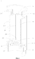
FIG. 1 shows a schematic cross-sectional perspective view of an electronic cigarette in accordance with a preferred embodiment of the present invention. -
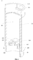
FIG. 2 shows a schematic cross-sectional perspective view of an outer housing of an electronic cigarette in accordance with a preferred embodiment of the present invention. -
FIG. 3 shows a schematic cross-sectional perspective view of an atomizing sheath of an electronic cigarette viewed from a preset viewing angle in accordance with a preferred embodiment of the present invention. -
FIG. 4 shows a schematic cross-sectional perspective view of the atomizing sheath of the electronic cigarette ofFIG. 3 viewed from another preset viewing angle in accordance with a preferred embodiment of the present invention. -
FIG. 5 shows a schematic exploded perspective view of an inhaling nozzle assembly of an electronic cigarette in accordance with another preferred embodiment of the present invention. -
FIG. 6 shows a schematic cross-sectional perspective view of an inhaling nozzle assembly of an electronic cigarette in accordance with a preferred embodiment of the present invention. - Illustration of reference numerals in attached drawings in accordance with a preferred embodiment of the present invention is as follows.
Electronic Cigarette 100Outer Housing 1Window 10Atomizing Sheath 2Liquid Storage Cavity 20First Sleeve Body 21Separating Wall 211Aerosol Output Passageway 212Second Protrusion 213Extending Portion 22Communicating Through Hole 220Fixing Sleeve Part 221Opening 222Airflow Path 223Second Sleeve Body 23Transitional Storage Cavity 230Base Seat 3Air Intake Passageway 30Gap 31Atomizing Core 4 Atomizing Passageway 40Porous Body 41 Heating Body 42Support Seat 5Seat Body 51Peripheral Wall 52Inhaling Nozzle Assembly 6Nozzle 61Aerosol Outlet 610Main Body 611Connecting Pillar 612Sealing Sleeve Part 613Vent 6130Engaging Wall 614Connecting Piece 615First Protrusion 616Sealing Piece 62Bottom Wall 621Communication Hole 6210Sleeve Wall 622Battery Assembly 7Controlling Assembly 8Lampshade 9 - In order to facilitate best understanding of the present invention, the present invention will be illustrated in more detail below in conjunction with the attached drawings and preferred embodiments. It should be noted that when an element is expressed as "being fixed to" another element, this element may be directly on the another element, or there may be one or more intervening elements between this element and the another element. When an element is expressed as "being connected to" another element, this element can be directly connected to the another element, or there may be one or more intervening elements between this element and the another element. In addition, terminology used in the specification, such as "up", "down", "left", "right", "inside", "outside", or similar expressions, is only used for descriptive purposes.
- Unless otherwise defined, any technical and scientific terminology used in this specification has the same meaning as commonly understood by those skilled in the technical field of the present invention. Terminology used in this specification of the present invention is only for a purpose of describing specific embodiments, and is not used to limit the present invention. Terminology such as "and/or" used in this specification includes any and all combinations of one or more related listed items.
- Atomizing liquid disclosed in the present invention can be liquid tobacco, medicine ingredients in a liquid state, or other aromatic ingredient substances volatile due to heating.
- Referring to
FIG. 1 , anelectronic cigarette 100 in accordance with a preferred embodiment of the present invention mainly includes anouter housing 1, anatomizing sheath 2, abase seat 3, an atomizing core 4, asupport seat 5, an inhalingnozzle assembly 6, abattery assembly 7, a controllingassembly 8 and alampshade 9. - Referring to
FIGS. 1-2 , theouter housing 1 is a lengthwise hollow cylindrical structure, i.e., a length of theouter housing 1 is much larger than a diameter of theouter housing 1. A circumferential wall of theouter housing 1 has at least onewindow 10. In the preferred embodiment, theouter housing 1 has sixwindows 10 in total. The sixwindows 10 are divided into two sets. Each of the two sets has threewindows 10 therein. A center connecting line of the threewindows 10 is parallel to a lengthwise direction of theouter housing 1, i.e., the threewindows 10 are equidistantly disposed on theouter housing 1 along the lengthwise direction of theouter housing 1. Each window of one of the two sets is located at a same height location as a corresponding window of the other of the two sets. - Referring to
FIGS. 1 and3-4 , theatomizing sheath 2 is received and fixed in theouter housing 1. A length of theatomizing sheath 2 is smaller than the length of theouter housing 1. An upper edge of theatomizing sheath 2 is substantially flush with an upper edge of theouter housing 1. An outer wall of theatomizing sheath 2 is attachably fixed to an inner wall of theouter housing 1. - The
atomizing sheath 2 is made by transparent and high-temperature tolerant plastic material, such as material of poly(1,4-cyclohexylene dimethylene terephthalate glycol) (Shorted for "PCTG"). PCTG is an amorphous copolyester. A commonly used comonomer in PCTG is cyclohexane dimethanol (CHDM), and therefore a full name of PCTG is poly(1,4-cyclohexylene dimethylene terephthalate glycol). PCTG is a polycondensation product under transesterification using three monomers including terephthalic acid (PTA), ethylene glycol (EG) and cyclohexane dimethanol (CHDM). In comparison to polyethylene terephthalate (PET), PCTG additionally includes a comonomer of cyclohexane dimethanol. In comparison to poly(1,4-cyclohexamethylene dimethylene terephthalate) (PCT), PCTG additionally includes a comonomer of ethylene glycol. - The
atomizing sheath 2 is substantially lengthwise cylindrical. An extendingportion 22 extends inwards from an inner wall of theatomizing sheath 2 to divide theatomizing sheath 2 into afirst sleeve body 21 and asecond sleeve body 23. The extendingportion 22 does not completely block thefirst sleeve body 21 from thesecond sleeve body 23 so that thefirst sleeve body 21 and thesecond sleeve body 23 are spatially communicated with each other. - Two separating
walls 211 are disposed in thefirst sleeve body 21. The two separatingwalls 211 are parallel to each other and oppositely disposed. The two separatingwalls 211 and thefirst sleeve body 21 cooperatively surround a space therebetween to form aliquid storage cavity 20.Aerosol output passageways 212 are disposed outside the separatingwalls 211, i.e., twoaerosol output passageways 212 are respectively disposed at two opposite sides of theliquid storage cavity 20. Either one of the twoaerosol output passageways 212 is cooperatively surrounded to be formed by thefirst sleeve body 21, a corresponding one of the two separatingwalls 211 and theouter housing 1. An upper edge of either one of the two separatingwalls 211 is lower than an upper edge of thefirst sleeve body 21. An indentation is formed and located above the either one of the two separatingwalls 211. Asecond protrusion 213 is disposed to extend toward a center of thefirst sleeve body 21 from an inner wall of an upper edge of the indentation. - The extending
portion 22 is located below thefirst sleeve body 21, and extends along a radial direction of thefirst sleeve body 21. Communicating throughholes 220 are respectively formed between front and rear sides of the extendingportion 22 and an inner wall of thefirst sleeve body 21, i.e., two communicating throughholes 220 are disposed at the extendingportion 22. A fixingsleeve part 221 extends from the extendingportion 22 along a direction facing away from thefirst sleeve body 21, i.e., the fixingsleeve part 221 extends downwards from the extendingportion 22. Anopening 222 are disposed at a location of the extendingportion 22 corresponding to the fixingsleeve part 221. Anairflow path 223 is disposed above the fixingsleeve part 221 and extends along a radial direction of theatomizing sheath 2. Theairflow path 223 is spatially communicated with the twoaerosol output passageways 212 located at its left and right sides. Theairflow path 223 is located between the two communicating throughholes 220 at its front and rear sides, i.e., the two communicating throughholes 220 are respectively located at two opposite sides of theairflow path 223. - The
second sleeve body 23 is formed to extend from the extendingportion 22 along the direction facing away from thefirst sleeve body 21, i.e., thesecond sleeve body 23 extends downwards from the extendingportion 22. A length of thesecond sleeve body 23 is smaller than a length of thefirst sleeve body 21. The fixingsleeve part 221 is accommodated in thesecond sleeve body 23. Atransitional storage cavity 230 is formed in thesecond sleeve body 23. The two communicating throughholes 220 of the extendingportion 22 are respectively spatially communicated between theliquid storage cavity 20 and thetransitional storage cavity 230. Since thetransitional storage cavity 230 is located below theliquid storage cavity 20, atomizing liquid stored in theliquid storage cavity 20 will flow to enter thetransitional storage cavity 230 through the two communicating throughholes 220 due to gravity. As a result, the atomizing liquid is transiently stored in thetransitional storage cavity 230. - The
base seat 3 is accommodated and fixed in thesecond sleeve body 23. Thebase seat 3 is made by material of silica gel. An outer wall of thebase seat 3 is snugly engaged for being fixed on an inner wall of thesecond sleeve body 23 in order to seal thetransitional storage cavity 230. Thebase seat 3 includes an accommodating cavity and anair intake passageway 30 penetrating between upper and lower sides of thebase seat 3. Agap 31 is formed between thebase seat 3 and the fixingsleeve part 221 along a lengthwise direction of theatomizing sheath 2. - The atomizing core 4 includes a porous body 41 and a
heating body 42. The porous body 41 is used to absorb atomizing liquid stored in theliquid storage cavity 20 and transiently store the absorbed atomizing liquid therein, i.e., function of the porous body 41 is conducting atomizing liquid. After being electrified, theheating body 42 heats atomizing liquid stored in the porous body 41 to generate aerosol for direct inhaling of users. The porous body 41 is a hollow cylindrical structure. In the preferred embodiment, the porous body 41 is made by porous ceramic. Understandably, the porous body 41 can be also made by foamed metal, porous glass or hard glass fiber tube. Theheating body 42 is integrally formed in an inner cavity of the porous body 41. Theheating body 42 is made by electrically connective metal material. Material to make theheating body 42 can be nickel, ferro nickel alloy, ferro chrome aluminum alloy, nickel chrome alloy, stainless steel or titanium alloy, etc. - An upper end of the porous body 41 is received and fixed in the fixing
sleeve part 221. A lower end of the porous body 41 is received and fixed in thebase seat 3. Atomizing liquid stored in thetransitional storage cavity 230 flows to the porous body 41 through thegap 31 between the fixingsleeve part 221 and thebase seat 3, and is permeantly conducted from an outer side of the porous body 41 to an inner side of the porous body 41 in order to be further heated and atomized by theheating body 42. As a result, aerosol is formed in anatomizing passageway 40 of the atomizing core 4 for direct inhaling of users. - The
support seat 5 is used to support thebase seat 3. Thesupport seat 5 includes aseat body 51 and aperipheral wall 52 extending upwards from theseat body 51. An upper end face of theseat body 51 is engaged with a lower end face of thebase seat 3. An air intake hole is disposed at a center of theseat body 51 to penetrate through theseat body 51 between an upper side of theseat body 51 and a lower side of theseat body 51. The air intake hole is spatially communicated with theair intake passageway 30. Theperipheral wall 52 surrounds around an outside of thesecond sleeve body 23. Thesupport seat 5 is made of plastic material having a certain strength, such as being made of material of ethylene-vinyl acetate copolymer (EVA). - Referring to
FIGS. 1 and5-6 , the inhalingnozzle assembly 6 includes anozzle 61 and a sealingpiece 62. Thenozzle 61 includes amain body 611. A lower end face of themain body 611 is engaged with an upper end face of theouter housing 1. A connectingpillar 612 extends downwards from a center of themain body 611. A sealingsleeve part 613 extends below the connectingpillar 612. Twovents 6130 are disposed on the sealingsleeve part 613. The twovents 6130 are respectively located at two opposite sides of the sealingsleeve part 613. Anengaging wall 614 is disposed outside a connecting location of the sealingsleeve part 613 and the connectingpillar 612. Theengaging wall 614 is engaged with an upper end face of the fixingsleeve part 221. - Two connecting
pieces 615 extend downwards from themain body 611. The two connectingpieces 615 are respectively located at two opposite sides of the connectingpillar 612. Each of the two connectingpieces 615 has a certain resilience and toughness. Afirst protrusion 616 extends at a distal end of the each of the two connectingpieces 615 along a direction facing away the connectingpillar 612. Thefirst protrusion 616 and thesecond protrusion 213 are engaged with each other. As a result, thenozzle 61 and theatomizing sheath 2 are undetachably connected. - An
aerosol outlet 610 penetrating the main body 611between upper and lower sides of themain body 611 is disposed in themain body 611. Theaerosol outlet 610 is spatially communicated with the twoaerosol output passageways 212. - The sealing
piece 62 is made by material of silica gel which has excellent resilience and ductility. The sealingpiece 62 can be resiliently deformed when being squeezed and/or pressed. The sealingpiece 62 includes abottom wall 621 and asleeve wall 622 extending upward from thebottom wall 621. Acommunication hole 6210 is disposed on thebottom wall 621 of the sealingpiece 62. Thesleeve wall 622 surrounds and is disposed outside the sealingsleeve part 613. The sealingsleeve part 613 is received in theliquid storage cavity 20. The sealingpiece 62 is used to seal a clearance between the sealingsleeve part 613, the two separatingwalls 211 and thefirst sleeve body 21. Thecommunication hole 6210 is spatially communicated with theliquid storage cavity 20 and the twovents 6130. - When the inhaling
nozzle assembly 6 is not yet assembled with theatomizing sheath 2, a clearance is formed between thesleeve wall 622 of the sealingpiece 62 and the sealingsleeve part 613. During a process of a side of the inhalingnozzle assembly 6 being gradually inserted into theatomizing sheath 2, remain air in theliquid storage cavity 20 will be discharged out of theliquid storage cavity 20 successively via the two communicating throughholes 6210 of the sealingpiece 62, the twovents 6130 of the sealingsleeve part 613 and the clearance between thesleeve wall 622 of the sealingpiece 62 and the sealingsleeve part 613. As a result, an upward force applied on the inhalingnozzle assembly 6 is avoided being generated by the remain excess air in theliquid storage cavity 20 being compressed, and thenozzle 61 is avoided being pushed out due to the remain air in theliquid storage cavity 20. - After the inhaling
nozzle assembly 6 is completely assembled with theatomizing sheath 2, thesleeve wall 622 of the sealingpiece 62 is located between the two separatingwalls 211 and the sealingsleeve part 613 and is squeezed and pressed to extend and deform so that thesleeve wall 622 can fill and block the clearance between the sealingsleeve part 613 and thefirst sleeve body 21. As a result, the atomizing liquid in theliquid storage cavity 20 can be avoided to leak from an upper side of theliquid storage cavity 20. - The
battery assembly 7 is received in and fixed to theouter housing 1. A clearance is formed between an outer wall of thebattery assembly 7 and the inner wall of theouter housing 1, and external air can enter the air intake hole of thesupport seat 5 through the clearance. Thebattery assembly 7 is located below thesupport seat 5. Thebattery assembly 7 is mainly used to supply electrical power to theheating body 42, and theheating body 42 generates heat after being electrified. As a result, atomizing liquid absorbed by the porous body 41 from thegap 31 between the fixingsleeve part 221 and thebase seat 3 is heated. - The controlling
assembly 8 is received in and fixed to thelampshade 9. Thelampshade 9 is located at a lower end of theouter housing 1. The controllingassembly 8 is used to control connection or disconnection between theheating body 42 and thebattery assembly 7. In a preferred embodiment of the present invention, the controllingassembly 8 can be a condenser microphone. Since a working principle of the condenser microphone is a common knowledge in the technical area, i.e., electrification of theheating body 42 to heat being controlled by the condenser microphone based on a sucking and inhaling action of users at thenozzle 61 is an existing technology in the technical area, details regarding the working principle of the condenser microphone is no longer repeated herein. - A clearance is formed between the
lampshade 9 and theouter housing 1. When users suck or inhale at thenozzle 61, the condenser microphone controls theheating body 42 being electrified to heat, and external air enters the atomizingpassageway 40 successively through the clearance formed between theouter housing 1 and thelampshade 9, the clearance formed between theouter housing 1 and thebattery assembly 7, the air intake hole of thesupport seat 5 and theair intake passageway 30 of thebase seat 3. The entering air in theatomizing passageway 40 can further carry aerosol generated in theatomizing passageway 40 to enter theairflow path 223 through theopening 222 of the extendingportion 22. Subsequently, the air carrying the aerosol is divided by theairflow path 223 to respectively flow into the twoaerosol output passageways 212 located at left and right two sides of theatomizing sheath 2. Finally, the air carrying the aerosol enters a mouth cavity or nasal cavity of users through theaerosol outlet 610 to provide the users with senses of stimulation and satisfaction. - In the present invention, the
extension portion 22 is disposed in theatomizing sheath 2 in accordance with the present invention. The extendingportion 22 has a hollow structure therein and forms theairflow path 223 penetrating a wall of theatomizing sheath 2. Theairflow path 223 is used to spatially communicate theatomizing passageway 40 in the atomizing core 4 with the at least oneaerosol output passageway 212 outside theatomizing sheath 2. As a result, a technical solution to discharge aerosol generated in theatomizing sheath 2 to the at least oneaerosol output passageway 212 outside theatomizing sheath 2 and a design to dispose the at least oneaerosol output passageway 212 outside theatomizing sheath 2 can be achieved. A volume of theliquid storage cavity 20 in theatomizing sheath 2 is increased and a liquid storage quantity of theelectronic cigarette 100 is therefore increased. In the present invention, an end of the atomizing core 4 is fixed to thebase seat 3, and the other end of the atomizing core 4 is fixed to the fixingsleeve part 221. Atomizing liquid in theliquid storage cavity 20 enters the atomizingpassageway 40 of the atomizing core 4 through thegap 31 between the fixingsleeve part 221 and thebase seat 3 to be atomized and form aerosol for directly inhaling and sucking. As a result, no outer sleeve tube is required to be disposed outside the atomizing core 4 of theelectronic cigarette 100 in accordance with the present invention. Production cost of theelectronic cigarette 100 is reduced and competition power in the market of theelectronic cigarette 100 is enhanced. - It should be noted that the specification of the present invention and its accompanying drawings provides preferred embodiments of the present invention. However, the present invention can be implemented in many different forms and is not limited to the preferred embodiments described in this specification. Examples, the preferred embodiments are not intended to make additional restrictions on the content of the present invention, and the purpose of providing the preferred embodiments is to make understanding of the disclosure of the present invention become more thorough and comprehensive. In addition, the above technical features continue to be combined with one another to form various embodiments not listed above, the combinations are all regarded as being within the scope of the description of the present invention. Furthermore, for those of ordinary skill in the art, improvements or transformations can be made based on the above descriptions, and all these improvements and transformations should belong to the protection scope of the appended claims of the present invention.
Claims (10)
- An electronic cigarette, comprising:an outer housing;an atomizing sheath received in the outer housing, at least one aerosol output passageway being defined between the outer housing and the atomizing sheath;an extending portion extending inwards from an inner wall of the atomizing sheath to divide the atomizing sheath into a first sleeve body and a second sleeve body for respectively storing atomizing liquid therein, the extending portion blocking incompletely the first sleeve body from the second sleeve body so that the first sleeve body and the second sleeve body are spatially communicated with each other;an atomizing core disposed in the second sleeve body, an atomizing passageway being formed in the atomizing core, the atomizing core used to atomize the atomizing liquid for generating aerosol and releasing the generated aerosol into the atomizing passageway;wherein the extending portion is a hollow structure to form an airflow path penetrating a wall of the atomizing sheath, the airflow path is used to spatially communicate the atomizing passageway with the at least one aerosol output passageway.
- The electronic cigarette as claimed in Claim 1, wherein the extending portion extends perpendicularly to a lengthwise direction of the atomizing sheath, a liquid storage cavity is formed in the first sleeve body, a transitional storage cavity is formed in the second sleeve body, a communicating through hole is disposed on the extending portion to spatially communicate the liquid storage cavity with the transitional storage cavity.
- The electronic cigarette as claimed in Claim 2, wherein the first sleeve body comprises two separating walls, the at least one aerosol output passageway is separated to become two aerosol output passageways respectively formed between the two separating walls and the outer housing, the two aerosol output passageways are respectively disposed at two opposite sides of the liquid storage cavity, and are respectively spatially communicated with the airflow path.
- The electronic cigarette as claimed in Claim 2, wherein the electronic cigarette further comprises a base seat, the base seat is accommodated and fixed in the second sleeve body, a fixing sleeve part extends from the extending portion toward the base seat, a gap is formed between the base seat and the fixing sleeve part along a lengthwise direction of the atomizing sheath, an end of the atomizing core is received in the fixing sleeve part, and the opposite other end of the atomizing core is received in the base seat, atomizing liquid stored in the transitional storage cavity enters the atomizing passageway of the atomizing core via the gap to be atomized.
- The electronic cigarette as claimed in Claim 2, wherein the communicating through hole is set as two communicating through holes, the two communicating through holes are respectively located at two opposite sides of the airflow path.
- The electronic cigarette as claimed in Claim 3, wherein the electronic cigarette further comprises an inhaling nozzle assembly, the inhaling nozzle assembly is disposed at one end of the atomizing sheath to seal the liquid storage cavity, an aerosol outlet is disposed on the inhaling nozzle assembly to be spatially communicated with the at least one aerosol output passageway.
- The electronic cigarette as claimed in Claim 6, wherein the inhaling nozzle assembly comprises a nozzle, the nozzle comprises a main body and a connecting piece extending from the main body toward the extending portion, a first protrusion is disposed at a distal end of the connecting piece, a second protrusion is disposed at the atomizing sheath to be engaged with the first protrusion, and the nozzle and the atomizing sheath are undetachably engaged with and fixed to each other.
- The electronic cigarette as claimed in Claim 7, wherein the inhaling nozzle assembly further comprises a sealing piece, a sealing sleeve part extends from the main body toward the extending portion, the sealing sleeve part is received in the liquid storage cavity, the sealing piece surrounds and is disposed outside the sealing sleeve part.
- The electronic cigarette as claimed in Claim 8, wherein a communication hole is disposed on the sealing piece, a vent is disposed at a sleeve wall of the sealing sleeve part, the communication hole and the vent are spatially communicated with each other.
- The electronic cigarette as claimed in Claim 1, wherein the outer housing is hollow, a circumferential wall of the outer housing comprises at least one window, the atomizing sheath is made by transparent material, a remaining quantity of atomizing liquid stored in the atomizing sheath is viewable from the at least one window.
Applications Claiming Priority (2)
| Application Number | Priority Date | Filing Date | Title |
|---|---|---|---|
| CN201822001919.9U CN209376699U (en) | 2018-11-30 | 2018-11-30 | Electronic cigarette |
| PCT/CN2019/115747 WO2020108246A1 (en) | 2018-11-30 | 2019-11-05 | Electronic cigarette |
Publications (3)
| Publication Number | Publication Date |
|---|---|
| EP3888478A1 true EP3888478A1 (en) | 2021-10-06 |
| EP3888478A4 EP3888478A4 (en) | 2022-01-12 |
| EP3888478B1 EP3888478B1 (en) | 2025-08-20 |
Family
ID=67870204
Family Applications (1)
| Application Number | Title | Priority Date | Filing Date |
|---|---|---|---|
| EP19889615.1A Active EP3888478B1 (en) | 2018-11-30 | 2019-11-05 | Electronic cigarette |
Country Status (4)
| Country | Link |
|---|---|
| US (1) | US11992049B2 (en) |
| EP (1) | EP3888478B1 (en) |
| CN (1) | CN209376699U (en) |
| WO (1) | WO2020108246A1 (en) |
Families Citing this family (11)
| Publication number | Priority date | Publication date | Assignee | Title |
|---|---|---|---|---|
| US12232527B2 (en) | 2021-05-31 | 2025-02-25 | Shenzhen First Union Technology Co., Ltd. | Electronic cigarette and nozzle assembly |
| CN209376699U (en) * | 2018-11-30 | 2019-09-13 | 深圳市合元科技有限公司 | Electronic cigarette |
| CN110574969B (en) * | 2019-09-17 | 2024-12-10 | 深圳雾芯科技有限公司 | Atomization device |
| CN214710337U (en) * | 2020-05-12 | 2021-11-16 | 深圳麦克韦尔科技有限公司 | Electronic atomization device and atomizer thereof |
| KR102513572B1 (en) * | 2020-07-09 | 2023-03-23 | 주식회사 케이티앤지 | Aerosol generating device |
| EP4212027A4 (en) | 2020-09-11 | 2023-11-15 | Shenzhen Smoore Technology Limited | ATOMIZER AND ELECTRONIC ATOMIZATION DEVICE INCLUDING SAME |
| CN112316257A (en) * | 2020-10-27 | 2021-02-05 | 深圳市康泓威科技有限公司 | Nebulizer with Integral Nebulizer Assembly and Reservoir Core |
| CN113952560B (en) * | 2021-10-26 | 2024-10-25 | 合肥启灏医疗科技有限公司 | Atomizer cup |
| WO2024032412A1 (en) * | 2022-08-12 | 2024-02-15 | 常州市派腾电子技术服务有限公司 | Atomization device and aerosol generating device |
| CN116391912A (en) * | 2023-05-22 | 2023-07-07 | 常州市派腾电子技术服务有限公司 | A nebulizer and an aerosol generating device |
| CN119548717B (en) * | 2024-06-06 | 2025-10-10 | 艾特申博(苏州)医药科技有限公司 | Elastic protective part, nozzle assembly and atomizing device |
Family Cites Families (17)
| Publication number | Priority date | Publication date | Assignee | Title |
|---|---|---|---|---|
| AT511344B1 (en) * | 2011-10-21 | 2012-11-15 | Helmut Dr Buchberger | INHALATORKOMPONENTE |
| CN204483015U (en) * | 2012-07-23 | 2015-07-22 | 惠州市吉瑞科技有限公司 | Electronic cigarette case and electronic cigarette device |
| CN203401203U (en) * | 2013-08-09 | 2014-01-22 | 辽宁鸿象钢管有限公司 | Longitudinal submerged arc welding scribed line floating limiting device |
| CN203660013U (en) * | 2013-09-29 | 2014-06-18 | 刘秋明 | Battery pack of electronic cigarette, atomization component and electronic cigarette |
| US10004267B2 (en) * | 2014-05-21 | 2018-06-26 | Huizhou Kimree Technology Co., Ltd. Shenzhen Branch | Atomization assembly and electronic cigarette |
| JP2017525348A (en) * | 2014-07-24 | 2017-09-07 | アルトリア クライアント サービシーズ リミテッド ライアビリティ カンパニー | Electronic cigarette device and its parts |
| CN104983076B (en) | 2015-06-15 | 2018-07-20 | 深圳麦克韦尔股份有限公司 | Inhalator and its battery component and atomizing component |
| EP3308661B1 (en) * | 2015-11-19 | 2020-10-21 | Fontem Holdings 1 B.V. | Module for powering an electronic smoking device portion |
| CN206423562U (en) * | 2016-11-28 | 2017-08-22 | 深圳市艾维普思科技股份有限公司 | Electronic cigarette and its double-deck oil-bearing structure |
| WO2018170848A1 (en) * | 2017-03-23 | 2018-09-27 | 惠州市吉瑞科技有限公司深圳分公司 | Atomizer |
| US10314340B2 (en) * | 2017-04-21 | 2019-06-11 | Rai Strategic Holdings, Inc. | Refillable aerosol delivery device and related method |
| CN207784278U (en) * | 2017-12-11 | 2018-08-31 | 深圳麦克韦尔股份有限公司 | Electronic cigarette and its atomizer |
| CN107951079B (en) * | 2017-12-11 | 2020-01-17 | 深圳麦克韦尔科技有限公司 | Electronic cigarette and atomizer thereof |
| CN207707306U (en) * | 2017-12-21 | 2018-08-10 | 上海新型烟草制品研究院有限公司 | A kind of atomizer and electronic cigarette |
| CN207767547U (en) * | 2017-12-25 | 2018-08-28 | 上海新型烟草制品研究院有限公司 | A kind of atomising device and its electronic cigarette |
| CN209234999U (en) | 2018-10-29 | 2019-08-13 | 深圳市合元科技有限公司 | Electronic cigarette |
| CN209376699U (en) * | 2018-11-30 | 2019-09-13 | 深圳市合元科技有限公司 | Electronic cigarette |
-
2018
- 2018-11-30 CN CN201822001919.9U patent/CN209376699U/en active Active
-
2019
- 2019-11-05 WO PCT/CN2019/115747 patent/WO2020108246A1/en not_active Ceased
- 2019-11-05 US US17/298,667 patent/US11992049B2/en active Active
- 2019-11-05 EP EP19889615.1A patent/EP3888478B1/en active Active
Also Published As
| Publication number | Publication date |
|---|---|
| EP3888478B1 (en) | 2025-08-20 |
| US11992049B2 (en) | 2024-05-28 |
| US20220015423A1 (en) | 2022-01-20 |
| CN209376699U (en) | 2019-09-13 |
| WO2020108246A1 (en) | 2020-06-04 |
Similar Documents
| Publication | Publication Date | Title |
|---|---|---|
| EP3888478B1 (en) | Electronic cigarette | |
| US20180279683A1 (en) | Atomoizer and electronic cigarette having the same | |
| CN211910517U (en) | Atomizers and Electronic Cigarettes | |
| KR20230162128A (en) | An aerosol delivery device and a related method | |
| US20250160406A1 (en) | Electronic cigarette and nozzle assembly | |
| EP3884788A1 (en) | Vaporizer and aerosol-generating apparatus comprising same | |
| KR20230019010A (en) | Seasoning component and electronic atomization device | |
| CN112869245A (en) | Electronic cigarette atomizing device and electronic cigarette thereof | |
| CN217791454U (en) | Atomizer | |
| CN216088865U (en) | Electronic cigarette atomizing device and electronic cigarette | |
| CN214229853U (en) | Atomizing device and electron cigarette | |
| US12232527B2 (en) | Electronic cigarette and nozzle assembly | |
| CN217364688U (en) | Atomizing core module, atomizer and electronic atomization device | |
| CN218337731U (en) | Atomizer and electronic atomization device | |
| CN216088866U (en) | Electron smog spinning disk atomiser's casing, electron smog spinning disk atomiser and electron cigarette | |
| WO2023207320A1 (en) | Electronic atomization device | |
| CN214483235U (en) | Electronic cigarette vaporizer | |
| CN216568391U (en) | Atomizer and electronic suction device with integrally formed outer cover and cigarette holder | |
| CN215775539U (en) | Electronic cigarette and atomization device thereof | |
| EP3945909B1 (en) | Multi-channel and reversed airflow mouthpiece for an aerosol- generating article | |
| CN215422809U (en) | An electronic cigarette atomizing device and electronic cigarette | |
| WO2023207314A1 (en) | Electronic atomization device and liquid storage and atomization assembly thereof | |
| EP3679812B1 (en) | Heating element, atomizer and electronic cigarette having same | |
| CN214047575U (en) | Aerosol-generating article heated by high-temperature aerosol | |
| CN112914157A (en) | Liquid leakage prevention atomizing bomb |
Legal Events
| Date | Code | Title | Description |
|---|---|---|---|
| STAA | Information on the status of an ep patent application or granted ep patent |
Free format text: STATUS: THE INTERNATIONAL PUBLICATION HAS BEEN MADE |
|
| PUAI | Public reference made under article 153(3) epc to a published international application that has entered the european phase |
Free format text: ORIGINAL CODE: 0009012 |
|
| STAA | Information on the status of an ep patent application or granted ep patent |
Free format text: STATUS: REQUEST FOR EXAMINATION WAS MADE |
|
| 17P | Request for examination filed |
Effective date: 20210630 |
|
| AK | Designated contracting states |
Kind code of ref document: A1 Designated state(s): AL AT BE BG CH CY CZ DE DK EE ES FI FR GB GR HR HU IE IS IT LI LT LU LV MC MK MT NL NO PL PT RO RS SE SI SK SM TR |
|
| STAA | Information on the status of an ep patent application or granted ep patent |
Free format text: STATUS: EXAMINATION IS IN PROGRESS |
|
| A4 | Supplementary search report drawn up and despatched |
Effective date: 20211213 |
|
| RIC1 | Information provided on ipc code assigned before grant |
Ipc: A61M 15/06 20060101ALI20211207BHEP Ipc: A24F 40/485 20200101ALI20211207BHEP Ipc: A24F 40/10 20200101AFI20211207BHEP |
|
| 17Q | First examination report despatched |
Effective date: 20220103 |
|
| DAV | Request for validation of the european patent (deleted) | ||
| DAX | Request for extension of the european patent (deleted) | ||
| REG | Reference to a national code |
Ref country code: DE Ref legal event code: R079 Free format text: PREVIOUS MAIN CLASS: A24F0047000000 Ipc: A24F0040100000 Ref country code: DE Ref legal event code: R079 Ref document number: 602019074544 Country of ref document: DE Free format text: PREVIOUS MAIN CLASS: A24F0047000000 Ipc: A24F0040100000 |
|
| REG | Reference to a national code |
Free format text: PREVIOUS MAIN CLASS: A24F0040100000 Ref country code: DE Ref legal event code: R079 Ref document number: 602019074544 Country of ref document: DE Ipc: A24F0040485000 |
|
| GRAP | Despatch of communication of intention to grant a patent |
Free format text: ORIGINAL CODE: EPIDOSNIGR1 |
|
| STAA | Information on the status of an ep patent application or granted ep patent |
Free format text: STATUS: GRANT OF PATENT IS INTENDED |
|
| RIC1 | Information provided on ipc code assigned before grant |
Ipc: A61M 11/04 20060101ALI20250410BHEP Ipc: A61M 15/06 20060101ALI20250410BHEP Ipc: A24F 40/485 20200101ALI20250410BHEP Ipc: A24F 40/10 20200101AFI20250410BHEP |
|
| RIC1 | Information provided on ipc code assigned before grant |
Ipc: A24F 40/10 20200101ALN20250428BHEP Ipc: A61M 11/04 20060101ALI20250428BHEP Ipc: A61M 15/06 20060101ALI20250428BHEP Ipc: A24F 40/485 20200101AFI20250428BHEP |
|
| INTG | Intention to grant announced |
Effective date: 20250509 |
|
| GRAS | Grant fee paid |
Free format text: ORIGINAL CODE: EPIDOSNIGR3 |
|
| GRAA | (expected) grant |
Free format text: ORIGINAL CODE: 0009210 |
|
| STAA | Information on the status of an ep patent application or granted ep patent |
Free format text: STATUS: THE PATENT HAS BEEN GRANTED |
|
| AK | Designated contracting states |
Kind code of ref document: B1 Designated state(s): AL AT BE BG CH CY CZ DE DK EE ES FI FR GB GR HR HU IE IS IT LI LT LU LV MC MK MT NL NO PL PT RO RS SE SI SK SM TR |
|
| REG | Reference to a national code |
Ref country code: GB Ref legal event code: FG4D |
|
| REG | Reference to a national code |
Ref country code: CH Ref legal event code: EP |
|
| REG | Reference to a national code |
Ref country code: IE Ref legal event code: FG4D |
|
| REG | Reference to a national code |
Ref country code: DE Ref legal event code: R096 Ref document number: 602019074544 Country of ref document: DE |
|
| REG | Reference to a national code |
Ref country code: NL Ref legal event code: MP Effective date: 20250820 |
|
| PG25 | Lapsed in a contracting state [announced via postgrant information from national office to epo] |
Ref country code: IS Free format text: LAPSE BECAUSE OF FAILURE TO SUBMIT A TRANSLATION OF THE DESCRIPTION OR TO PAY THE FEE WITHIN THE PRESCRIBED TIME-LIMIT Effective date: 20251220 |
|
| PGFP | Annual fee paid to national office [announced via postgrant information from national office to epo] |
Ref country code: DE Payment date: 20251117 Year of fee payment: 7 |
|
| PGFP | Annual fee paid to national office [announced via postgrant information from national office to epo] |
Ref country code: GB Payment date: 20251126 Year of fee payment: 7 |
|
| PG25 | Lapsed in a contracting state [announced via postgrant information from national office to epo] |
Ref country code: NO Free format text: LAPSE BECAUSE OF FAILURE TO SUBMIT A TRANSLATION OF THE DESCRIPTION OR TO PAY THE FEE WITHIN THE PRESCRIBED TIME-LIMIT Effective date: 20251120 |
|
| REG | Reference to a national code |
Ref country code: LT Ref legal event code: MG9D |
|
| PG25 | Lapsed in a contracting state [announced via postgrant information from national office to epo] |
Ref country code: PT Free format text: LAPSE BECAUSE OF FAILURE TO SUBMIT A TRANSLATION OF THE DESCRIPTION OR TO PAY THE FEE WITHIN THE PRESCRIBED TIME-LIMIT Effective date: 20251222 |
|
| PG25 | Lapsed in a contracting state [announced via postgrant information from national office to epo] |
Ref country code: FI Free format text: LAPSE BECAUSE OF FAILURE TO SUBMIT A TRANSLATION OF THE DESCRIPTION OR TO PAY THE FEE WITHIN THE PRESCRIBED TIME-LIMIT Effective date: 20250820 |
|
| PG25 | Lapsed in a contracting state [announced via postgrant information from national office to epo] |
Ref country code: HR Free format text: LAPSE BECAUSE OF FAILURE TO SUBMIT A TRANSLATION OF THE DESCRIPTION OR TO PAY THE FEE WITHIN THE PRESCRIBED TIME-LIMIT Effective date: 20250820 Ref country code: NL Free format text: LAPSE BECAUSE OF FAILURE TO SUBMIT A TRANSLATION OF THE DESCRIPTION OR TO PAY THE FEE WITHIN THE PRESCRIBED TIME-LIMIT Effective date: 20250820 |
|
| PGFP | Annual fee paid to national office [announced via postgrant information from national office to epo] |
Ref country code: FR Payment date: 20251127 Year of fee payment: 7 |
|
| PG25 | Lapsed in a contracting state [announced via postgrant information from national office to epo] |
Ref country code: GR Free format text: LAPSE BECAUSE OF FAILURE TO SUBMIT A TRANSLATION OF THE DESCRIPTION OR TO PAY THE FEE WITHIN THE PRESCRIBED TIME-LIMIT Effective date: 20251121 |
|
| PG25 | Lapsed in a contracting state [announced via postgrant information from national office to epo] |
Ref country code: SE Free format text: LAPSE BECAUSE OF FAILURE TO SUBMIT A TRANSLATION OF THE DESCRIPTION OR TO PAY THE FEE WITHIN THE PRESCRIBED TIME-LIMIT Effective date: 20250820 |
|
| PG25 | Lapsed in a contracting state [announced via postgrant information from national office to epo] |
Ref country code: LV Free format text: LAPSE BECAUSE OF FAILURE TO SUBMIT A TRANSLATION OF THE DESCRIPTION OR TO PAY THE FEE WITHIN THE PRESCRIBED TIME-LIMIT Effective date: 20250820 |
|
| PG25 | Lapsed in a contracting state [announced via postgrant information from national office to epo] |
Ref country code: PL Free format text: LAPSE BECAUSE OF FAILURE TO SUBMIT A TRANSLATION OF THE DESCRIPTION OR TO PAY THE FEE WITHIN THE PRESCRIBED TIME-LIMIT Effective date: 20250820 Ref country code: BG Free format text: LAPSE BECAUSE OF FAILURE TO SUBMIT A TRANSLATION OF THE DESCRIPTION OR TO PAY THE FEE WITHIN THE PRESCRIBED TIME-LIMIT Effective date: 20250820 |
|
| PG25 | Lapsed in a contracting state [announced via postgrant information from national office to epo] |
Ref country code: RS Free format text: LAPSE BECAUSE OF FAILURE TO SUBMIT A TRANSLATION OF THE DESCRIPTION OR TO PAY THE FEE WITHIN THE PRESCRIBED TIME-LIMIT Effective date: 20251120 |
|
| PG25 | Lapsed in a contracting state [announced via postgrant information from national office to epo] |
Ref country code: ES Free format text: LAPSE BECAUSE OF FAILURE TO SUBMIT A TRANSLATION OF THE DESCRIPTION OR TO PAY THE FEE WITHIN THE PRESCRIBED TIME-LIMIT Effective date: 20250820 |
|
| REG | Reference to a national code |
Ref country code: AT Ref legal event code: MK05 Ref document number: 1826334 Country of ref document: AT Kind code of ref document: T Effective date: 20250820 |
|
| PG25 | Lapsed in a contracting state [announced via postgrant information from national office to epo] |
Ref country code: RO Free format text: LAPSE BECAUSE OF FAILURE TO SUBMIT A TRANSLATION OF THE DESCRIPTION OR TO PAY THE FEE WITHIN THE PRESCRIBED TIME-LIMIT Effective date: 20250820 |
|
| PG25 | Lapsed in a contracting state [announced via postgrant information from national office to epo] |
Ref country code: SM Free format text: LAPSE BECAUSE OF FAILURE TO SUBMIT A TRANSLATION OF THE DESCRIPTION OR TO PAY THE FEE WITHIN THE PRESCRIBED TIME-LIMIT Effective date: 20250820 |
|
| PG25 | Lapsed in a contracting state [announced via postgrant information from national office to epo] |
Ref country code: DK Free format text: LAPSE BECAUSE OF FAILURE TO SUBMIT A TRANSLATION OF THE DESCRIPTION OR TO PAY THE FEE WITHIN THE PRESCRIBED TIME-LIMIT Effective date: 20250820 |
|
| PG25 | Lapsed in a contracting state [announced via postgrant information from national office to epo] |
Ref country code: AT Free format text: LAPSE BECAUSE OF FAILURE TO SUBMIT A TRANSLATION OF THE DESCRIPTION OR TO PAY THE FEE WITHIN THE PRESCRIBED TIME-LIMIT Effective date: 20250820 |
|
| PG25 | Lapsed in a contracting state [announced via postgrant information from national office to epo] |
Ref country code: IT Free format text: LAPSE BECAUSE OF FAILURE TO SUBMIT A TRANSLATION OF THE DESCRIPTION OR TO PAY THE FEE WITHIN THE PRESCRIBED TIME-LIMIT Effective date: 20250820 |
|
| PG25 | Lapsed in a contracting state [announced via postgrant information from national office to epo] |
Ref country code: CZ Free format text: LAPSE BECAUSE OF FAILURE TO SUBMIT A TRANSLATION OF THE DESCRIPTION OR TO PAY THE FEE WITHIN THE PRESCRIBED TIME-LIMIT Effective date: 20250820 |
|
| PG25 | Lapsed in a contracting state [announced via postgrant information from national office to epo] |
Ref country code: SK Free format text: LAPSE BECAUSE OF FAILURE TO SUBMIT A TRANSLATION OF THE DESCRIPTION OR TO PAY THE FEE WITHIN THE PRESCRIBED TIME-LIMIT Effective date: 20250820 Ref country code: EE Free format text: LAPSE BECAUSE OF FAILURE TO SUBMIT A TRANSLATION OF THE DESCRIPTION OR TO PAY THE FEE WITHIN THE PRESCRIBED TIME-LIMIT Effective date: 20250820 |