EP3888058B1 - Positioning marker - Google Patents
Positioning marker Download PDFInfo
- Publication number
- EP3888058B1 EP3888058B1 EP19890849.3A EP19890849A EP3888058B1 EP 3888058 B1 EP3888058 B1 EP 3888058B1 EP 19890849 A EP19890849 A EP 19890849A EP 3888058 B1 EP3888058 B1 EP 3888058B1
- Authority
- EP
- European Patent Office
- Prior art keywords
- cover
- base
- openings
- retroreflective
- plane
- Prior art date
- Legal status (The legal status is an assumption and is not a legal conclusion. Google has not performed a legal analysis and makes no representation as to the accuracy of the status listed.)
- Active
Links
Images



Classifications
-
- A—HUMAN NECESSITIES
- A61—MEDICAL OR VETERINARY SCIENCE; HYGIENE
- A61B—DIAGNOSIS; SURGERY; IDENTIFICATION
- A61B90/00—Instruments, implements or accessories specially adapted for surgery or diagnosis and not covered by any of the groups A61B1/00 - A61B50/00, e.g. for luxation treatment or for protecting wound edges
- A61B90/39—Markers, e.g. radio-opaque or breast lesions markers
-
- A—HUMAN NECESSITIES
- A61—MEDICAL OR VETERINARY SCIENCE; HYGIENE
- A61B—DIAGNOSIS; SURGERY; IDENTIFICATION
- A61B34/00—Computer-aided surgery; Manipulators or robots specially adapted for use in surgery
- A61B34/20—Surgical navigation systems; Devices for tracking or guiding surgical instruments, e.g. for frameless stereotaxis
-
- A—HUMAN NECESSITIES
- A61—MEDICAL OR VETERINARY SCIENCE; HYGIENE
- A61B—DIAGNOSIS; SURGERY; IDENTIFICATION
- A61B90/00—Instruments, implements or accessories specially adapted for surgery or diagnosis and not covered by any of the groups A61B1/00 - A61B50/00, e.g. for luxation treatment or for protecting wound edges
- A61B90/36—Image-producing devices or illumination devices not otherwise provided for
-
- G—PHYSICS
- G02—OPTICS
- G02B—OPTICAL ELEMENTS, SYSTEMS OR APPARATUS
- G02B5/00—Optical elements other than lenses
- G02B5/12—Reflex reflectors
- G02B5/136—Reflex reflectors plural reflecting elements forming part of a unitary body
-
- A—HUMAN NECESSITIES
- A61—MEDICAL OR VETERINARY SCIENCE; HYGIENE
- A61B—DIAGNOSIS; SURGERY; IDENTIFICATION
- A61B34/00—Computer-aided surgery; Manipulators or robots specially adapted for use in surgery
- A61B34/20—Surgical navigation systems; Devices for tracking or guiding surgical instruments, e.g. for frameless stereotaxis
- A61B2034/2046—Tracking techniques
- A61B2034/2055—Optical tracking systems
- A61B2034/2057—Details of tracking cameras
-
- A—HUMAN NECESSITIES
- A61—MEDICAL OR VETERINARY SCIENCE; HYGIENE
- A61B—DIAGNOSIS; SURGERY; IDENTIFICATION
- A61B90/00—Instruments, implements or accessories specially adapted for surgery or diagnosis and not covered by any of the groups A61B1/00 - A61B50/00, e.g. for luxation treatment or for protecting wound edges
- A61B90/36—Image-producing devices or illumination devices not otherwise provided for
- A61B2090/364—Correlation of different images or relation of image positions in respect to the body
- A61B2090/365—Correlation of different images or relation of image positions in respect to the body augmented reality, i.e. correlating a live optical image with another image
-
- A—HUMAN NECESSITIES
- A61—MEDICAL OR VETERINARY SCIENCE; HYGIENE
- A61B—DIAGNOSIS; SURGERY; IDENTIFICATION
- A61B90/00—Instruments, implements or accessories specially adapted for surgery or diagnosis and not covered by any of the groups A61B1/00 - A61B50/00, e.g. for luxation treatment or for protecting wound edges
- A61B90/36—Image-producing devices or illumination devices not otherwise provided for
- A61B90/37—Surgical systems with images on a monitor during operation
- A61B2090/371—Surgical systems with images on a monitor during operation with simultaneous use of two cameras
-
- A—HUMAN NECESSITIES
- A61—MEDICAL OR VETERINARY SCIENCE; HYGIENE
- A61B—DIAGNOSIS; SURGERY; IDENTIFICATION
- A61B90/00—Instruments, implements or accessories specially adapted for surgery or diagnosis and not covered by any of the groups A61B1/00 - A61B50/00, e.g. for luxation treatment or for protecting wound edges
- A61B90/36—Image-producing devices or illumination devices not otherwise provided for
- A61B90/37—Surgical systems with images on a monitor during operation
- A61B2090/372—Details of monitor hardware
-
- A—HUMAN NECESSITIES
- A61—MEDICAL OR VETERINARY SCIENCE; HYGIENE
- A61B—DIAGNOSIS; SURGERY; IDENTIFICATION
- A61B90/00—Instruments, implements or accessories specially adapted for surgery or diagnosis and not covered by any of the groups A61B1/00 - A61B50/00, e.g. for luxation treatment or for protecting wound edges
- A61B90/39—Markers, e.g. radio-opaque or breast lesions markers
- A61B2090/3937—Visible markers
-
- A—HUMAN NECESSITIES
- A61—MEDICAL OR VETERINARY SCIENCE; HYGIENE
- A61B—DIAGNOSIS; SURGERY; IDENTIFICATION
- A61B90/00—Instruments, implements or accessories specially adapted for surgery or diagnosis and not covered by any of the groups A61B1/00 - A61B50/00, e.g. for luxation treatment or for protecting wound edges
- A61B90/39—Markers, e.g. radio-opaque or breast lesions markers
- A61B2090/3966—Radiopaque markers visible in an X-ray image
-
- A—HUMAN NECESSITIES
- A61—MEDICAL OR VETERINARY SCIENCE; HYGIENE
- A61B—DIAGNOSIS; SURGERY; IDENTIFICATION
- A61B90/00—Instruments, implements or accessories specially adapted for surgery or diagnosis and not covered by any of the groups A61B1/00 - A61B50/00, e.g. for luxation treatment or for protecting wound edges
- A61B90/39—Markers, e.g. radio-opaque or breast lesions markers
- A61B2090/3983—Reference marker arrangements for use with image guided surgery
-
- A—HUMAN NECESSITIES
- A61—MEDICAL OR VETERINARY SCIENCE; HYGIENE
- A61B—DIAGNOSIS; SURGERY; IDENTIFICATION
- A61B90/00—Instruments, implements or accessories specially adapted for surgery or diagnosis and not covered by any of the groups A61B1/00 - A61B50/00, e.g. for luxation treatment or for protecting wound edges
- A61B90/50—Supports for surgical instruments, e.g. articulated arms
- A61B2090/502—Headgear, e.g. helmet, spectacles
Definitions
- the present invention relates generally to a fiducial marker, and specifically to a marker that can be tracked optically.
- US Patent 4,863,238 to Brewster describes a reflective marker for marking an object such as a highway pole and the like by reflective light.
- the reflective marker comprises a support layer, and a top plate affixed thereto having die-cut portions adapted, when removed, to form openings which cooperate with the support layer to define shallow recesses in the marker.
- US Patent 6,609,022 to Vilsmeier, et al. describes a method for supporting the treatment of a patient, including a navigation system detecting and tracking the positions of the patient, of his/her parts of the body, and of the target of the treatment and the treatment devices.
- US Patent 7,874,686 to Rossner, et al. describes a reflective marker and a method for manufacturing the marker.
- the reflective marker includes an inner body and a reflective covering, and a reflective substance is applied to the inner body and forms the reflective covering together with pellets contained in the substance or applied after the substance has been applied.
- US Patent 8,950,877 to Northey, et al. describes retroreflective sheeting that includes a first portion of prismatic retroreflective sheeting having a first cube corner structure that creates a first visual feature in the retroreflective sheeting and a second portion of prismatic retroreflective sheeting having a second cube corner structure.
- US Patent Application 2011/0216411 to Reed, et al. describes retro-reflective sheeting comprising a flexible optical material film or substrate having a geometric optical surface opposite a base surface.
- the geometric optical surface includes a background pattern region of corner cubes arranged at a first orientation with respect to an edge of the retro-reflective sheeting.
- US Patent Application 2012/0143050 to Heigl describes a reference foil comprising an unsymmetric marker foil device which includes spatially separated pieces of a marker material foil in an unsymmetric arrangement and/or at least one unsymmetric integral piece of the marker material foil.
- the reference foil and a carrier device for the same may be used for example in image-guided surgery.
- US Patent Application 2015/0351863 to Plassky, et al. describes a marker for optical medical navigation, comprising a structure with at least one recess, and at least one supporting element, wherein each supporting element is configured to be accommodated within a particular recess.
- US Patent Application 2016/0175064 to Steinle, et al. describes a medical navigation marker device comprising a light reflector, characterized in that the reflector features a marker pattern that points in more than one spatial direction.
- German Patent DE202004011567 assigned to Aesculap AG describes how the position of a surgical instrument is defined by a marker integrated in the tool or a bone screw and is transmitted to a processing unit by infrared radiation reflected by a special element.
- the element is punched out of a suitable material preferably in a round shape and held in a frame located at the marker.
- European Patent Application EP1640750A1 to Mosimann, et al. describes a retro-reflective device having at least a body comprising salient elements on an external surface of the body.
- the body is made of at least one first material entity made of a homogeneous compound of plastic material with on one hand elements entirely coated with at least one reflective layer and fully embedded inside the plastic material, and on the other hand salient elements partially coated with a same reflective layer.
- PCT Patent Application WO2015058816 to Vasey, et al. describes a hybrid medical marker for use in a medical navigation system, the marker comprising a marker core which comprises a contrast medium and an outer surface which is at least partly light-reflective.
- US2017086941 discloses a marker having a support with a front surface and a back surface, a light generating element fixed on the back surface of the support, and a device for fixation of the light generating element on the back surface, wherein the support includes at least three openings placed at predetermined positions on the support, wherein the light generating element is fixed on the back surface of the support by the device for fixation to cover the openings such that the light generating element is detectable through the openings by the tracking system, and wherein the light generating element can be placed or removed or replaced during an operation with the device for fixation
- a positioning marker as set out in the first of the appending independent claims.
- a method for producing a positioning marker as set out in the second of the appending independent claims.
- a positioning marker comprising a base having a retroreflective surface; and a cover, which is fitted over and fastened to the base and has a plurality of openings through which the retroreflective surface is visible.
- the openings are right conical frusta.
- the frusta may terminate in respective first shapes and second shapes smaller than the first shapes, and the second shapes contact the retroreflective surface when the cover is fastened to the base, forming respective retroreflectors.
- the respective retroreflectors may be arranged on a flat plane.
- the retroreflective surface includes a base flat surface
- the cover includes a cover flat surface which mates with the base flat surface when the cover is fastened to the base, so that respective sections of the openings contact the retroreflective surface.
- the base includes a first sheet configured in a first plane, and the openings generate respective retroreflectors from the retroreflective surface and in the first plane when the cover is fastened to the base, the cover including a further opening, the marker including a second sheet having a further retroreflective surface configured in a second plane parallel to and distinct from the first plane, so that the further retroreflective surface is visible through the further opening when the cover is fastened to the base.
- the further opening is a right conical frustum.
- the base may include a central aperture, and the right conical frustum may penetrate the central aperture when the cover is fastened to the base.
- the support may be a support protruding from the cover, the support including a support plane, aligned with the second plane, configured to fit to the second sheet.
- Examples may include a cover retainer which is configured to be fixedly connected to the cover and to retain the base in fixed contact with the cover, so as to fasten the base to the cover.
- the base includes a central aperture
- the cover includes a first connecting element
- the cover retainer includes a second connecting element mating with the first connecting element so as to fasten the cover to the cover retainer and the base, and at least one of the connecting elements penetrates the central aperture.
- the retroreflective surface includes at least one of retroreflective tape and retroreflective paint.
- a method for producing a positioning marker comprising forming a retroreflective surface on a base; and fitting a cover over and fastening the cover to the base, wherein the cover has a plurality of openings through which the retroreflective surface is visible.
- Embodiments of the present invention provide a positioning marker which facilitates the registration referred to above, by enabling a processor coupled to the augmented reality assembly to track the marker, and to maintain the tracking even when large changes of angle, subtended by the marker to the assembly, occur.
- the positioning marker comprises a base, typically in the form of a rectangular plane sheet with a central aperture, and the sheet has a retroreflective surface.
- a marker cover is fitted over and is fastened to the base, and the cover has a plurality of openings through which the retroreflective surface of the base is visible.
- the openings in the cover are typically in the form of right conical frusta, the conical shape of the openings allowing retroreflectors formed in the retroreflective surface by the openings to be visible even when the large changes of angle referred to above occur.
- the retroreflectors are typically configured to be in a given plane, and in order to enhance the tracking provided by the marker, the marker may comprise a further retroreflector located in a plane different from the given plane.
- the further retroreflector may be formed by providing a further opening in the form of a right conical frustum in the cover, the frustum of the further opening having a different depth from the depth of the frusta described above. Having all the openings of the cover in the form of frusta enables the retroreflectors formed by the openings to be visible even when large changes of angle occur.
- the marker typically comprises a cover retainer which can be fixedly attached to the cover while fastening the base to the cover.
- the base is “sandwiched" between the cover retainer and the cover, and the further reflector is also sandwiched between the cover retainer and the cover.
- FIG. 1 schematically illustrates use of a positioning marker 18 in an augmented reality system 20, according to an embodiment of the present invention.
- system 20 is assumed to be used by a medical professional 22 in a medical procedure.
- embodiments of the present invention may be used in non-medical situations, such as in operating a video game, in simulating a real-world event, or in providing an aid to navigation.
- System 20 is operated by medical professional 22, who wears an augmented reality assembly 24, described in more detail below with respect to Fig. 2 . While assembly 24 may be incorporated for wearing into a number of different retaining structures on professional 22, in the present description the retaining structure is assumed to be similar to a pair of spectacles. Those having ordinary skill in the augmented reality art will be aware of other possible structures, such as incorporation of the augmented reality assembly into a head-up display that is integrated into a helmet worn by the user of system 20.
- System 20 comprises and is under overall control of a processor 26.
- processor 26 is assumed to be incorporated within a stand-alone computer 28, and the processor typically communicates with other elements of the system, including assembly 24, wirelessly, as is illustrated in Fig. 1 .
- processor 26 may use optical and/or conducting cables for communication.
- processor 26 may be integrated within assembly 24, or in the mounting of the assembly.
- Processor 26 is typically able to access a database 40, wherein are stored images and other visual elements used by system 20.
- Software enabling processor 26 to operate system 20 may be downloaded to the processor in electronic form, over a network, for example.
- the software may be provided on non-transitory tangible media, such as optical, magnetic, or electronic storage media.
- ROI 34 typically, but not necessarily, comprises a portion of the patient.
- professional 22 enables processor 26 to identify the ROI by locating positioning marker 18, described in more detail below, at a predefined location with respect to ROI 34, e.g., the ROI may be a predefined distance to the right and a predefined distance below marker 18.
- processor 26 is able to track the location of marker 18, and thus, since the marker is at a predefined location with respect to ROI 34, the processor is able to track the location of the ROI.
- positioning marker 18, or a marker substantially similar to marker 18, may be attached to a tool or other device used in the procedure.
- processor 26 is able to track the marker and thus the tool or device attached to the marker.
- marker 18 is assumed to be used as a stand-alone element for tracking ROI 34, but those having skill in the art will be able to adapt the description, mutatis mutandis, for the case when the marker is attached to a tool or other deice to be tracked using the marker.
- Fig. 2 is a schematic diagram illustrating assembly 24, as well as functions that may be implemented in the assembly, according to an embodiment of the present invention.
- assembly 24 is configured, by way of example, as a pair of spectacles 50. Similar elements of each "half" of the pair of spectacles are referred to generically by an identifying numeral, and the similar elements are differentiated as necessary by adding a letter to the numeral.
- spectacles 50 comprise planar optical combiners 52, comprising combiners 52A and 52B in front of, respectively, the left and right eyes of professional 22.
- Optical combiners 52 are mounted on a retaining structure 54 which holds elements of assembly 24, and which is herein assumed to comprise a spectacle frame, so that structure 54 is also referred to herein as frame 54.
- combiner frames 82A and 82B are fixed to retaining structure 54 and vertical retaining rods 84A and 84B attached to the combiner frames support the optical combiners, so that the combiners are able to rotate about vertical axes defined by the rods.
- Retaining rods 84A and 84B, and thus combiners 52A and 52B may be rotated independently of each other about their vertical axes by respective motors 86A and 86B, fixed to frames 82A and 82B.
- Motors 86 typically stepper motors, are controlled by processor 26 so as to rotate their attached combiners to known, typically different, fixed orientations with respect to their respective combiner frames.
- Each optical combiner 52 is configured to at least partially transmit elements of a scene through the combiner, so that a portion 56 of patient 30 ( Fig. 1 ) is assumed to be directly visible through each combiner 52.
- each optical combiner 52 is configured to receive a visible radiation transmission derived from a scene, and/or a visual transmission such as a presentation of data or a marker, and to redirect or reflect the transmission back to the eye of professional 22.
- Optical combiners of various types are known in the art.
- One known type uses a semi reflective surface which transmits an image from an image source after it has passed through a set of lenses which correct deformations caused by the semi reflective surface of the combiner.
- Another known type uses a waveguide which projects the image directly to the eye of the viewer.
- combiners 52 are assumed to be of the waveguide type.
- pixelated variable transparency screens 60A and 60B respectively coat a rear side, i.e., the side away from the eyes of professional 22, of combiners 52A, 52B.
- Screens 60 are active elements of system 20 and are formed of an array of pixels, the opacity of each of the pixels being controlled by processor 26.
- Screens 60 are typically, but not necessarily, liquid crystal displays (LCDs) formed of a rectangular array of liquid crystal pixels.
- LCDs liquid crystal displays
- screens 60 are formed of MEMS (microelectromechanical systems).
- PDLCs polymer dispersed liquid crystals
- micro-projectors 64A and 64B Fixedly attached to arms of frame 54 are generally similar micro-projectors 64A and 64B. Each micro-projector is located and oriented so as to be able to project onto respective combiner 52A and 52B, a scene, and/or a visual indication, in a form suitable for redirection by the combiners to the left or right eye of professional 22.
- Micro-projectors 64 are active elements, and the projected scenes/indications are provided to the micro-projectors by processor 26.
- the projection and redirection are configured so that the images seen by the eyes of professional 22, absent any correcting lenses, appear to be at infinity, due to parallel light coming from the combiners and entering the pupils.
- assembly 24 comprises correcting lenses 88A, 88B which redirect light from combiners 52A, 52B so that the images appear to be closer than infinity to the professional's eyes.
- At least one image capturing device 68 is attached to frame 54.
- devices 68 comprise cameras configured to capture images of scenes viewed by the professional, including images of marker 18 in the visible spectrum.
- assembly 24 comprises a sensor 72, also herein termed a camera 72, which is configured to capture images of elements of a scene, including marker 18, in front of assembly 24.
- the images, which include images of marker 18, are produced from radiation projected by a projector 73 that is in the spectrum detected by camera 72.
- Projector 73 is located in close proximity to camera 72, so that radiation from the projector, that has been retroreflected, is captured by camera 72.
- the camera typically has a bandpass filter configured to block other radiation, such as that projected by surgical lighting.
- camera 72 and projector 73 operate in a non-visible region of the spectrum, such as in the near infra-red spectrum.
- processor 26 uses the image of the marker produced by camera 72 from the received radiation to track the marker and ROI 34.
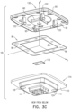
- Fig. 3A is a schematic top view of marker 18
- Fig. 3B is a schematic exploded view of the marker as viewed from above
- Fig. 3C is a schematic exploded view of the marker as viewed from below, according to an embodiment of the present invention.
- the views have been drawn on a set of orthogonal xyz axes.
- marker 18 comprises a flat planar sheet 80 having a generally rectangular shape and a generally rectangular aperture 84 formed within the sheet.
- Flat planar sheet 80 has a lower flat plane surface 88.
- Sheet 80 acts as a base for marker 18, and is also herein termed base 80.
- upper surface 86 of base 80 is retroreflective, and in one embodiment the surface is formed to be retroreflective by adhering retroreflective tape to the upper surface.
- other methods, such as covering with retroreflective paint, for making surface 86 retroreflective will be apparent to those having skill in the art.
- base 80 Fitted over, and fastened to, base 80 is an inflexible opaque base cover 90, which has a lower plane surface 92 and an upper surface 94.
- base cover 90 When cover 90 is fastened to base 80, as described below, surface 92 of the cover mates with upper surface 86 of the base.
- Cover 90 has a plurality of openings 98, within the cover, which penetrate the top and bottom surfaces of the cover. Openings 98 are substantially congruent to each other, and each opening has the form of a right conical frustum, terminating in a first opening 106 in upper surface 94, and a second opening 102, smaller than opening 106 and herein termed smaller opening 106, in lower plane surface 92. Typically, as shown in the figure and as assumed for clarity and simplicity in the following description, openings 102 and 106 are circular. However, embodiments of the present invention comprise other shapes for the openings, such as regular or irregular polygons.
- cover 90 When cover 90 is fastened to base 80, surface 92 of the cover mates with the retroreflective upper surface of base 80, and smaller circular openings 102 contact base 80, forming retroreflective circles 96, herein termed retroflectors 96.
- cover 90 illustrate cover 90 as having twelve openings, through each of which the retroreflective upper surface of base 80 is visible, but it will be understood that embodiments of the present invention may have fewer or more than twelve openings.
- the centers of retroflectors 96 are formed on a square having a center on the z-axis.
- the spacing of the retroflectors on the square is configured to be non-symmetrical, so that processor 26 may determine a unique orientation of marker 18 from images of the retroflectors.
- the spacing of the retroflectors is also configured so that processor 26 may determine a unique orientation of marker 18 from images of the retroflectors.
- openings 98 as frusta, it will be appreciated that the retroreflective upper surface of base 80 is visible, through the openings, from many different directions. This visibility facilitates the ability of processor 26 to track marker 18 using camera 72 if there is relative motion between the camera and the marker, for example if professional 22 moves.
- marker 18 In order to fasten base 80 to cover 90, marker 18 comprises a cover retainer 110 which has an upper flat plane surface 114. When marker 18 is assembled, the upper flat surface of the cover retainer mates with lower surface 88 of marker base 80. Also, for assembly, cover 90 comprises a lip 95 an inner edge of which mates with a perimeter of retainer 110. In addition, and as described above, when marker 18 is assembled upper retroreflective surface 86 of base 80 mates with lower plane surface 92 of cover 90.
- cover retainer 110 comprises one or more retainer connecting elements 118, which align with cover connecting elements 122 in cover 90.
- marker 18 comprises four elements 118 and four elements 122.
- Retainer connecting elements 118 comprise cylindrical holes, also herein termed holes 118, which penetrate retainer 110, and cover connecting elements 122 comprise sprung anchors, also herein termed anchors 122, which are dimensioned to align with and penetrate holes 118.
- anchors 122 In the assembled form of marker 18, i.e., when base 80 is fastened to cover 90 and cover retainer 110 mates with the lower surface of the base, anchors 122 hold the three entities (the cover, the base, and the cover retainer) fixedly in place.
- anchors 122 In order to act as marker anchors, anchors 122 are dimensioned so that in a compressed form they are able to penetrate holes 118. The holes and the anchors are further dimensioned to permit the anchors to expand to an uncompressed form when the base, the cover and the cover retainer are in their assembled state, so as to fixedly hold the marker elements in place.
- the elements of marker 18 may "snap" together, by anchors 122 reverting to their uncompressed form and engage ledges 124 in holes 118, by applying moderate pressure to the cover and the cover retainer.
- the marker comprises an additional opening 130 in cover 90, and an associated additional retroreflective surface 134 formed on an additional sheet 136.
- Retroreflective surface 134 is typically formed in substantially the same manner as retroreflective surface 86, for example by adhering retroreflective tape to surface 134.
- additional sheet 136 may be implemented as adhesive retroreflecting tape that is adhered to an internal surface of recessed portion 150 (described further below) of cover retainer 110.
- additional sheet 136 is assumed to have retroreflective material formed on surface 134, and those having ordinary skill in the art will be able to adapt the description, mutatis mutandis, for the case when sheet 136 is implemented as adhesive reflecting tape.
- additional opening 130 and additional retroreflective surface 134 are configured to form a section 138 of the additional retroreflective surface that is in a different plane from the plane of sections of the retroreflective upper surface formed by openings 102, i.e., from the plane defined by equation (1).
- section 138 is formed to be circular, and for simplicity in the following description it is considered to be circular.
- section 138 is configured to be symmetrical with the square, i.e. to be located on the z-axis.
- section 138 is indented from the plane of openings 102, so that n is a negative number.
- Additional opening 130 is formed, like openings 98, as a right conical frustum, and the opening is formed in a lower, downwardly-protruding, section 140 of cover 90.
- opening 130 has a first circular opening 144 in upper surface 94, and a second, smaller, circular opening 148 in a lower surface of downwardly-protruding section 140.
- the frustum formed by additional opening 130 has a different depth from the depths of the frusta of openings 98.
- section 140 When marker 18 is assembled, section 140 protrudes through aperture 84 of base 80, and enters into a recessed portion 150 of cover retainer 110.
- Sheet 136 With its retroreflective surface uppermost, is cemented onto an upper surface of portion 150.
- Smaller circular opening 148 and the upper surface of portion 150 are dimensioned so that when marker 18 is assembled, with its elements fixed in place, smaller circular opening 148 contacts sheet 136, and circular section 138 and its retroreflective surface is exposed by the circular opening and is visible through opening 130.
- Circular section 138 is herein also termed retroreflector 138.
- opening 130 By forming opening 130 as a frustum, retroreflector 138 is visible (as with retroflectors 96 of openings 98) from many different directions, so facilitating the ability of processor 26 to track marker 18 using camera 72.
- smaller circular opening 148 has a diameter of 5 mm
- opening 130 is a circular conical frustum having a conical angle of 120°.
- the positions of the connecting elements are selected so as not to interfere with the functioning of retroreflectors 96 and 138.
- the positions of the connecting elements are provided by way of example, and those having ordinary skill in the art will be aware of other connecting element positions that do not interfere with the functioning of the retroreflectors.
- tracking marker 18 to track ROI 34
- those having ordinary skill in the art will be able to adapt the description, mutatis mutandis, if the marker is used for other tracking purposes, such as being attached to a tool in order to track the tool.
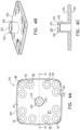
- Figs. 4A, 4B, and 4C are schematic diagrams of a cover 290 for a marker 218, according to an alternative embodiment of the present invention.
- Fig 4A is a top view of the cover
- Fig. 4B is a perspective view of the cover
- Fig. 4C is a cross-section of the cover taken along a line 4C-4C of Fig. 4A .
- cover 290 is generally similar to that of cover 90 ( Figs. 3A, 3B , and 3C ), and elements indicated by the same reference numerals in both covers are generally similar in construction and in operation.
- cover 290 comprises a support 228 for an elevated additional opening 230.
- Support 228 protrudes from cover 290.
- Opening 230 herein assumed to be generally similar to openings 98, is a right conical frustum terminating in a first opening 202 and a second opening 206, smaller than the first opening.
- Second opening 206 is formed in a lower internal plane surface 292 of support 228.
- marker 218 a base substantially identical to base 80, and having a retroreflective upper surface as described above for base 80, is fastened to a lower plane surface 294 of cover 290.
- a sheet similar to sheet 136 is fit to surface 292, the sheet having an upper reflective surface, visible through opening 206, and having dimensions modified from those for marker 18 so as to fit within support 228.
- a plane of the modified sheet aligns with lower internal plane surface 292.
- Marker 218 also comprises a cover retainer similar to retainer 110, but modified to support modified sheet 136 in contact with surface 292.
- Fig. 5 is a flowchart of steps performed in producing marker 18, according to an embodiment of the present invention. Those having ordinary skill in the art will be able to adapt the following description, mutatis mutandis, for producing marker 218.
- the separate marker elements i.e., base 80, base cover 90, cover retainer 110, and sheet 136 are produced according to predetermined dimensions.
- Base 80 and sheet 136 may be produced by any convenient means known in the art, for example by stamping, and their upper surfaces may be made retroreflective as described above.
- Cover 90 may be produced, for example, from a mold. Other methods for producing the cover will be apparent to those having skill in the art, but the method chosen should ensure that there is accurate and consistent positioning of smaller circular openings 102 and 148 with respect to each other.
- the material for the cover is typically an inflexible plastic such as polyimide.
- the marker elements are assembled generally as illustrated in Figs. 3B and 3C .
- sheet 136 with its retroreflective surface uppermost, may be adhered to an upper surface of recessed portion 150 of cover retainer 110.
- a final assembly step 368 moderate pressure is applied to the upper surface of cover 90 and the lower surface of retainer 110, so that anchors 122 engage ledges 124 so as to fixedly connect all the elements of the marker.
- base 80 and sheet 136 are effectively "sandwiched" between cover 90 and cover retainer 110.
Landscapes
- Health & Medical Sciences (AREA)
- Life Sciences & Earth Sciences (AREA)
- Surgery (AREA)
- Engineering & Computer Science (AREA)
- General Health & Medical Sciences (AREA)
- Nuclear Medicine, Radiotherapy & Molecular Imaging (AREA)
- Animal Behavior & Ethology (AREA)
- Public Health (AREA)
- Veterinary Medicine (AREA)
- Biomedical Technology (AREA)
- Heart & Thoracic Surgery (AREA)
- Medical Informatics (AREA)
- Molecular Biology (AREA)
- Pathology (AREA)
- Oral & Maxillofacial Surgery (AREA)
- Physics & Mathematics (AREA)
- Robotics (AREA)
- Optics & Photonics (AREA)
- General Physics & Mathematics (AREA)
- Length Measuring Devices By Optical Means (AREA)
- Illuminated Signs And Luminous Advertising (AREA)
- Light Guides In General And Applications Therefor (AREA)
- Golf Clubs (AREA)
- Pens And Brushes (AREA)
- Measurement Of The Respiration, Hearing Ability, Form, And Blood Characteristics Of Living Organisms (AREA)
- Connection Of Plates (AREA)
- Optical Elements Other Than Lenses (AREA)
Description
- The present invention relates generally to a fiducial marker, and specifically to a marker that can be tracked optically.
- During image guide surgery it is typically necessary to track objects used in the surgery, and/or elements of the patient undergoing the surgery. It may also be necessary to track and/or observe objects in other fields. A number of methods for performing such tracking or observation are known.
-
US Patent 4,863,238 to Brewster describes a reflective marker for marking an object such as a highway pole and the like by reflective light. The reflective marker comprises a support layer, and a top plate affixed thereto having die-cut portions adapted, when removed, to form openings which cooperate with the support layer to define shallow recesses in the marker. -
US Patent 6,609,022 to Vilsmeier, et al. describes a method for supporting the treatment of a patient, including a navigation system detecting and tracking the positions of the patient, of his/her parts of the body, and of the target of the treatment and the treatment devices. -
US Patent 7,364,314 to Nilsen, et al. describes optical structures and methods for manufacturing the same which include a substrate and a plurality of two-sided optical components disposed along the substrate. Retroreflective optical structures are also provided. -
US Patent 7,874,686 to Rossner, et al. describes a reflective marker and a method for manufacturing the marker. The reflective marker includes an inner body and a reflective covering, and a reflective substance is applied to the inner body and forms the reflective covering together with pellets contained in the substance or applied after the substance has been applied. -
US Patent 8,950,877 to Northey, et al. describes retroreflective sheeting that includes a first portion of prismatic retroreflective sheeting having a first cube corner structure that creates a first visual feature in the retroreflective sheeting and a second portion of prismatic retroreflective sheeting having a second cube corner structure. -
US Patent Application 2011/0216411 to Reed, et al. describes retro-reflective sheeting comprising a flexible optical material film or substrate having a geometric optical surface opposite a base surface. The geometric optical surface includes a background pattern region of corner cubes arranged at a first orientation with respect to an edge of the retro-reflective sheeting. -
US Patent Application 2012/0143050 to Heigl describes a reference foil comprising an unsymmetric marker foil device which includes spatially separated pieces of a marker material foil in an unsymmetric arrangement and/or at least one unsymmetric integral piece of the marker material foil. The reference foil and a carrier device for the same may be used for example in image-guided surgery. -
US Patent Application 2012/0182605 to Hall, et al. describes passive infrared markers which are reflective in the thermal and/or near infrared wavebands. -
US Patent Application 2015/0351863 to Plassky, et al. describes a marker for optical medical navigation, comprising a structure with at least one recess, and at least one supporting element, wherein each supporting element is configured to be accommodated within a particular recess. -
US Patent Application 2016/0175064 to Steinle, et al. describes a medical navigation marker device comprising a light reflector, characterized in that the reflector features a marker pattern that points in more than one spatial direction. - German Patent
DE202004011567 assigned to Aesculap AG describes how the position of a surgical instrument is defined by a marker integrated in the tool or a bone screw and is transmitted to a processing unit by infrared radiation reflected by a special element. The element is punched out of a suitable material preferably in a round shape and held in a frame located at the marker. - European Patent Application
EP1640750A1 to Mosimann, et al. describes a retro-reflective device having at least a body comprising salient elements on an external surface of the body. The body is made of at least one first material entity made of a homogeneous compound of plastic material with on one hand elements entirely coated with at least one reflective layer and fully embedded inside the plastic material, and on the other hand salient elements partially coated with a same reflective layer. -
PCT Patent Application WO2015058816 to Vasey, et al. describes a hybrid medical marker for use in a medical navigation system, the marker comprising a marker core which comprises a contrast medium and an outer surface which is at least partly light-reflective. -
US2017086941 discloses a marker having a support with a front surface and a back surface, a light generating element fixed on the back surface of the support, and a device for fixation of the light generating element on the back surface, wherein the support includes at least three openings placed at predetermined positions on the support, wherein the light generating element is fixed on the back surface of the support by the device for fixation to cover the openings such that the light generating element is detectable through the openings by the tracking system, and wherein the light generating element can be placed or removed or replaced during an operation with the device for fixation - According to an aspect of the present invention, there is provided a positioning marker as set out in the first of the appending independent claims. According to another aspect of the present invention, there is provided a method for producing a positioning marker as set out in the second of the appending independent claims. Features of various embodiments are set out in the appending dependent claims.
- There is also disclosed herein examples of a positioning marker, comprising a base having a retroreflective surface; and a cover, which is fitted over and fastened to the base and has a plurality of openings through which the retroreflective surface is visible.
- In examples, the openings are right conical frusta. The frusta may terminate in respective first shapes and second shapes smaller than the first shapes, and the second shapes contact the retroreflective surface when the cover is fastened to the base, forming respective retroreflectors. The respective retroreflectors may be arranged on a flat plane.
- In examples, the retroreflective surface includes a base flat surface, and the cover includes a cover flat surface which mates with the base flat surface when the cover is fastened to the base, so that respective sections of the openings contact the retroreflective surface.
- In examples, the base includes a first sheet configured in a first plane, and the openings generate respective retroreflectors from the retroreflective surface and in the first plane when the cover is fastened to the base, the cover including a further opening, the marker including a second sheet having a further retroreflective surface configured in a second plane parallel to and distinct from the first plane, so that the further retroreflective surface is visible through the further opening when the cover is fastened to the base.
- In examples, the further opening is a right conical frustum.
- The base may include a central aperture, and the right conical frustum may penetrate the central aperture when the cover is fastened to the base.
- Alternatively, there may be a support protruding from the cover, the support including a support plane, aligned with the second plane, configured to fit to the second sheet.
- Examples may include a cover retainer which is configured to be fixedly connected to the cover and to retain the base in fixed contact with the cover, so as to fasten the base to the cover. Typically, the base includes a central aperture, the cover includes a first connecting element, and the cover retainer includes a second connecting element mating with the first connecting element so as to fasten the cover to the cover retainer and the base, and at least one of the connecting elements penetrates the central aperture.
- In examples, the retroreflective surface includes at least one of retroreflective tape and retroreflective paint.
- There is also disclosed herein examples of a method for producing a positioning marker, comprising forming a retroreflective surface on a base; and fitting a cover over and fastening the cover to the base, wherein the cover has a plurality of openings through which the retroreflective surface is visible.
- The present disclosure will be more fully understood from the following detailed description of the embodiments thereof, taken together with the drawings, in which:
-
Fig. 1 schematically illustrates use of a positioning marker in an augmented reality system; -
Fig. 2 is a schematic diagram illustrating an assembly used in the system, as well as functions that may be implemented in the assembly; -
Fig. 3A is a schematic top view of the positioning marker,Fig. 3B is a schematic exploded view of the marker as viewed from above, andFig. 3C is a schematic exploded view of the marker as viewed from below; -
Figs. 4A, 4B, and 4C are schematic diagrams of a cover for a positioning marker; and -
Fig. 5 is a flowchart of steps performed in producing a positioning marker. - In an augmented reality environment, as well as in other environments, it is often necessary to register frames of reference of different elements of a system being used. For example, in the case of augmented reality, the frame of reference of an assembly mounted on the head of a user of an augmented reality system typically needs to be registered with the scene being viewed through the assembly.
- Embodiments of the present invention provide a positioning marker which facilitates the registration referred to above, by enabling a processor coupled to the augmented reality assembly to track the marker, and to maintain the tracking even when large changes of angle, subtended by the marker to the assembly, occur.
- The positioning marker comprises a base, typically in the form of a rectangular plane sheet with a central aperture, and the sheet has a retroreflective surface. A marker cover is fitted over and is fastened to the base, and the cover has a plurality of openings through which the retroreflective surface of the base is visible. The openings in the cover are typically in the form of right conical frusta, the conical shape of the openings allowing retroreflectors formed in the retroreflective surface by the openings to be visible even when the large changes of angle referred to above occur.
- The retroreflectors are typically configured to be in a given plane, and in order to enhance the tracking provided by the marker, the marker may comprise a further retroreflector located in a plane different from the given plane. The further retroreflector may be formed by providing a further opening in the form of a right conical frustum in the cover, the frustum of the further opening having a different depth from the depth of the frusta described above. Having all the openings of the cover in the form of frusta enables the retroreflectors formed by the openings to be visible even when large changes of angle occur.
- In order to fixedly fasten the cover to the base the marker typically comprises a cover retainer which can be fixedly attached to the cover while fastening the base to the cover. Typically the base is "sandwiched" between the cover retainer and the cover, and the further reflector is also sandwiched between the cover retainer and the cover.
- In the following, all directional references (e.g., upper, lower, upward, downward, left, right, top, bottom, above, below, vertical, and horizontal) are only used for identification purposes to aid the reader's understanding of the present invention, and do not create limitations, particularly as to the position, orientation, or use of embodiments of the invention.
- Reference is now made to
Fig. 1 , which schematically illustrates use of apositioning marker 18 in anaugmented reality system 20, according to an embodiment of the present invention. By way of example and for simplicity, in the followingdescription system 20 is assumed to be used by a medical professional 22 in a medical procedure. However, it will be understood that embodiments of the present invention may be used in non-medical situations, such as in operating a video game, in simulating a real-world event, or in providing an aid to navigation. -
System 20 is operated by medical professional 22, who wears an augmentedreality assembly 24, described in more detail below with respect toFig. 2 . Whileassembly 24 may be incorporated for wearing into a number of different retaining structures on professional 22, in the present description the retaining structure is assumed to be similar to a pair of spectacles. Those having ordinary skill in the augmented reality art will be aware of other possible structures, such as incorporation of the augmented reality assembly into a head-up display that is integrated into a helmet worn by the user ofsystem 20. -
System 20 comprises and is under overall control of aprocessor 26. In oneembodiment processor 26 is assumed to be incorporated within a stand-alone computer 28, and the processor typically communicates with other elements of the system, includingassembly 24, wirelessly, as is illustrated inFig. 1 . Alternatively or additionally,processor 26 may use optical and/or conducting cables for communication. Further alternatively or additionally,processor 26 may be integrated withinassembly 24, or in the mounting of the assembly.Processor 26 is typically able to access adatabase 40, wherein are stored images and other visual elements used bysystem 20.Software enabling processor 26 to operatesystem 20 may be downloaded to the processor in electronic form, over a network, for example. Alternatively or additionally, the software may be provided on non-transitory tangible media, such as optical, magnetic, or electronic storage media. - The medical procedure exemplified here is on a
patient 30, and during the procedure professional 22 gazes alonggaze directions 32 at a region of interest (ROI) 34.ROI 34 typically, but not necessarily, comprises a portion of the patient. In embodiments of the present invention professional 22 enablesprocessor 26 to identify the ROI by locatingpositioning marker 18, described in more detail below, at a predefined location with respect toROI 34, e.g., the ROI may be a predefined distance to the right and a predefined distance belowmarker 18. As is also described below,processor 26 is able to track the location ofmarker 18, and thus, since the marker is at a predefined location with respect toROI 34, the processor is able to track the location of the ROI. - Alternatively or additionally, positioning
marker 18, or a marker substantially similar tomarker 18, may be attached to a tool or other device used in the procedure. In thiscase processor 26 is able to track the marker and thus the tool or device attached to the marker. For clarity and simplicity, except where stated otherwise, in the followingdescription marker 18 is assumed to be used as a stand-alone element for trackingROI 34, but those having skill in the art will be able to adapt the description, mutatis mutandis, for the case when the marker is attached to a tool or other deice to be tracked using the marker. -
Fig. 2 is a schematicdiagram illustrating assembly 24, as well as functions that may be implemented in the assembly, according to an embodiment of the present invention. As stated above,assembly 24 is configured, by way of example, as a pair ofspectacles 50. Similar elements of each "half" of the pair of spectacles are referred to generically by an identifying numeral, and the similar elements are differentiated as necessary by adding a letter to the numeral. Thusspectacles 50 comprise planar optical combiners 52, comprisingcombiners structure 54 which holds elements ofassembly 24, and which is herein assumed to comprise a spectacle frame, so thatstructure 54 is also referred to herein asframe 54. - In some embodiments, combiner frames 82A and 82B are fixed to retaining
structure 54 andvertical retaining rods rods combiners respective motors frames Motors 86, typically stepper motors, are controlled byprocessor 26 so as to rotate their attached combiners to known, typically different, fixed orientations with respect to their respective combiner frames. - Each optical combiner 52 is configured to at least partially transmit elements of a scene through the combiner, so that a
portion 56 of patient 30 (Fig. 1 ) is assumed to be directly visible through each combiner 52. In addition, each optical combiner 52 is configured to receive a visible radiation transmission derived from a scene, and/or a visual transmission such as a presentation of data or a marker, and to redirect or reflect the transmission back to the eye of professional 22. - Optical combiners of various types are known in the art. One known type uses a semi reflective surface which transmits an image from an image source after it has passed through a set of lenses which correct deformations caused by the semi reflective surface of the combiner. Another known type uses a waveguide which projects the image directly to the eye of the viewer. Herein, by way of example, combiners 52 are assumed to be of the waveguide type.
- Generally similar pixelated
variable transparency screens combiners system 20 and are formed of an array of pixels, the opacity of each of the pixels being controlled byprocessor 26. - Screens 60 are typically, but not necessarily, liquid crystal displays (LCDs) formed of a rectangular array of liquid crystal pixels. Alternatively, screens 60 are formed of MEMS (microelectromechanical systems). Further alternatively, screens 60 are formed of polymer dispersed liquid crystals (PDLCs).
- Fixedly attached to arms of
frame 54 are generallysimilar micro-projectors respective combiner processor 26. The projection and redirection are configured so that the images seen by the eyes of professional 22, absent any correcting lenses, appear to be at infinity, due to parallel light coming from the combiners and entering the pupils. In someembodiments assembly 24 comprises correctinglenses combiners - At least one image capturing device 68 is attached to frame 54. In a disclosed embodiment there are two generally
similar devices planar combiners marker 18 in the visible spectrum. - In embodiments of the present invention,
assembly 24 comprises asensor 72, also herein termed acamera 72, which is configured to capture images of elements of a scene, includingmarker 18, in front ofassembly 24. The images, which include images ofmarker 18, are produced from radiation projected by aprojector 73 that is in the spectrum detected bycamera 72.Projector 73 is located in close proximity tocamera 72, so that radiation from the projector, that has been retroreflected, is captured bycamera 72. The camera typically has a bandpass filter configured to block other radiation, such as that projected by surgical lighting. Typically,camera 72 andprojector 73 operate in a non-visible region of the spectrum, such as in the near infra-red spectrum. As is described below, at least some retroreflected radiation is received frommarker 18, andprocessor 26 uses the image of the marker produced bycamera 72 from the received radiation to track the marker andROI 34. - An assembly similar to
assembly 24 is described inUS Patent 9,928,629 to Benishti et al. -
Fig. 3A is a schematic top view ofmarker 18,Fig. 3B is a schematic exploded view of the marker as viewed from above, andFig. 3C is a schematic exploded view of the marker as viewed from below, according to an embodiment of the present invention. For clarity the views have been drawn on a set of orthogonal xyz axes. In a disclosedembodiment marker 18 comprises a flatplanar sheet 80 having a generally rectangular shape and a generallyrectangular aperture 84 formed within the sheet. By way of example, anupper surface 86 ofsheet 80 is assumed to be on an xy plane of the xyz axes, and the upper surface is assumed to have an equation given by equation (1):
- A center of
sheet 80 is assumed to be at the origin of the xyz axes, i.e., at a location given by equation (2):
- Flat
planar sheet 80 has a lowerflat plane surface 88. -
Sheet 80 acts as a base formarker 18, and is also herein termedbase 80. In embodiments of the present inventionupper surface 86 ofbase 80 is retroreflective, and in one embodiment the surface is formed to be retroreflective by adhering retroreflective tape to the upper surface. However, other methods, such as covering with retroreflective paint, for makingsurface 86 retroreflective will be apparent to those having skill in the art. - Fitted over, and fastened to,
base 80 is an inflexibleopaque base cover 90, which has alower plane surface 92 and anupper surface 94. Whencover 90 is fastened tobase 80, as described below,surface 92 of the cover mates withupper surface 86 of the base. -
Cover 90 has a plurality ofopenings 98, within the cover, which penetrate the top and bottom surfaces of the cover.Openings 98 are substantially congruent to each other, and each opening has the form of a right conical frustum, terminating in afirst opening 106 inupper surface 94, and asecond opening 102, smaller than opening 106 and herein termedsmaller opening 106, inlower plane surface 92. Typically, as shown in the figure and as assumed for clarity and simplicity in the following description,openings - When
cover 90 is fastened tobase 80,surface 92 of the cover mates with the retroreflective upper surface ofbase 80, and smallercircular openings 102contact base 80, formingretroreflective circles 96, herein termedretroflectors 96. By way of example, the figures illustratecover 90 as having twelve openings, through each of which the retroreflective upper surface ofbase 80 is visible, but it will be understood that embodiments of the present invention may have fewer or more than twelve openings. - In one embodiment the centers of
retroflectors 96 are formed on a square having a center on the z-axis. However, the spacing of the retroflectors on the square is configured to be non-symmetrical, so thatprocessor 26 may determine a unique orientation ofmarker 18 from images of the retroflectors. In embodiments where the centers ofretroflectors 96 are not formed on a square, the spacing of the retroflectors is also configured so thatprocessor 26 may determine a unique orientation ofmarker 18 from images of the retroflectors. - By implementing
openings 98 as frusta, it will be appreciated that the retroreflective upper surface ofbase 80 is visible, through the openings, from many different directions. This visibility facilitates the ability ofprocessor 26 to trackmarker 18 usingcamera 72 if there is relative motion between the camera and the marker, for example if professional 22 moves. - The inventors have found that accurate tracking of
marker 18, using images of the retroreflective upper surface formed by smallercircular openings 102, is contingent on accurate and consistent positioning of the smaller circular openings with respect to each other. Such accurate and consistent positioning is facilitated by separately producing the openings in the cover, and then attaching the base retroreflective surface to the cover, as in embodiments of the present invention. For example, in an embodiment where the cover is a square of approximately 54 mm side, the tolerances on the dimensions ofopenings - In order to fasten
base 80 to cover 90,marker 18 comprises acover retainer 110 which has an upperflat plane surface 114. Whenmarker 18 is assembled, the upper flat surface of the cover retainer mates withlower surface 88 ofmarker base 80. Also, for assembly, cover 90 comprises alip 95 an inner edge of which mates with a perimeter ofretainer 110. In addition, and as described above, whenmarker 18 is assembled upperretroreflective surface 86 ofbase 80 mates withlower plane surface 92 ofcover 90. - In addition,
cover retainer 110 comprises one or moreretainer connecting elements 118, which align withcover connecting elements 122 incover 90. By way ofexample marker 18 comprises fourelements 118 and fourelements 122. -
Retainer connecting elements 118 comprise cylindrical holes, also herein termedholes 118, which penetrateretainer 110, andcover connecting elements 122 comprise sprung anchors, also herein termedanchors 122, which are dimensioned to align with and penetrateholes 118. - In the assembled form of
marker 18, i.e., whenbase 80 is fastened to cover 90 and coverretainer 110 mates with the lower surface of the base, anchors 122 hold the three entities (the cover, the base, and the cover retainer) fixedly in place. In order to act as marker anchors, anchors 122 are dimensioned so that in a compressed form they are able to penetrateholes 118. The holes and the anchors are further dimensioned to permit the anchors to expand to an uncompressed form when the base, the cover and the cover retainer are in their assembled state, so as to fixedly hold the marker elements in place. Typically, the elements ofmarker 18 may "snap" together, byanchors 122 reverting to their uncompressed form and engageledges 124 inholes 118, by applying moderate pressure to the cover and the cover retainer. - Connecting elements for
marker 18, other than the holes and anchors described above, will be apparent to those having skill in the art. - Smaller
circular openings 102, and the sections of the retroreflective upper surface exposed by the openings, are in a single plane, having an equation given by equation (1). - To further facilitate tracking of
marker 18, the marker comprises anadditional opening 130 incover 90, and an associated additionalretroreflective surface 134 formed on anadditional sheet 136.Retroreflective surface 134 is typically formed in substantially the same manner asretroreflective surface 86, for example by adhering retroreflective tape tosurface 134. - In some embodiments, rather than having an additional sheet upon a surface of which retroreflective material is formed,
additional sheet 136 may be implemented as adhesive retroreflecting tape that is adhered to an internal surface of recessed portion 150 (described further below) ofcover retainer 110. For clarity in the following descriptionadditional sheet 136 is assumed to have retroreflective material formed onsurface 134, and those having ordinary skill in the art will be able to adapt the description, mutatis mutandis, for the case whensheet 136 is implemented as adhesive reflecting tape. - As explained below,
additional opening 130 and additionalretroreflective surface 134 are configured to form asection 138 of the additional retroreflective surface that is in a different plane from the plane of sections of the retroreflective upper surface formed byopenings 102, i.e., from the plane defined by equation (1).Section 138 is in an xy plane indented or elevated from the plane of equation (1), and thus has an equation given by equation (3):
- Typically
section 138 is formed to be circular, and for simplicity in the following description it is considered to be circular. In the embodiment described above where the centers ofretroreflectors 96 are on a square,section 138 is configured to be symmetrical with the square, i.e. to be located on the z-axis. - In the embodiment illustrated in
Figs. 3A, 3B ,3C section 138 is indented from the plane ofopenings 102, so that n is a negative number. -
Additional opening 130 is formed, likeopenings 98, as a right conical frustum, and the opening is formed in a lower, downwardly-protruding,section 140 ofcover 90. Insection 140opening 130 has a firstcircular opening 144 inupper surface 94, and a second, smaller,circular opening 148 in a lower surface of downwardly-protrudingsection 140. The frustum formed byadditional opening 130 has a different depth from the depths of the frusta ofopenings 98. - When
marker 18 is assembled,section 140 protrudes throughaperture 84 ofbase 80, and enters into a recessedportion 150 ofcover retainer 110.Sheet 136, with its retroreflective surface uppermost, is cemented onto an upper surface ofportion 150. Smallercircular opening 148 and the upper surface ofportion 150 are dimensioned so that whenmarker 18 is assembled, with its elements fixed in place, smallercircular opening 148contacts sheet 136, andcircular section 138 and its retroreflective surface is exposed by the circular opening and is visible throughopening 130.Circular section 138 is herein also termedretroreflector 138. - By forming
opening 130 as a frustum,retroreflector 138 is visible (as withretroflectors 96 of openings 98) from many different directions, so facilitating the ability ofprocessor 26 to trackmarker 18 usingcamera 72. In the square embodiment referred to above, smallercircular opening 148 has a diameter of 5 mm, andopening 130 is a circular conical frustum having a conical angle of 120°. - In the embodiments described above the positions of the connecting elements (
elements 118 and 122) are selected so as not to interfere with the functioning ofretroreflectors - While the description above has addressed using
tracking marker 18 to trackROI 34, those having ordinary skill in the art will be able to adapt the description, mutatis mutandis, if the marker is used for other tracking purposes, such as being attached to a tool in order to track the tool. -
Figs. 4A, 4B, and 4C are schematic diagrams of acover 290 for amarker 218, according to an alternative embodiment of the present invention.Fig 4A is a top view of the cover,Fig. 4B is a perspective view of the cover, andFig. 4C is a cross-section of the cover taken along aline 4C-4C ofFig. 4A . Apart from the differences described below, the operation ofcover 290 is generally similar to that of cover 90 (Figs. 3A, 3B , and3C ), and elements indicated by the same reference numerals in both covers are generally similar in construction and in operation. - Rather than the
additional opening 130 ofcover 90, which forms anindented section 138,cover 290 comprises asupport 228 for an elevatedadditional opening 230.Support 228 protrudes fromcover 290.Opening 230, herein assumed to be generally similar toopenings 98, is a right conical frustum terminating in afirst opening 202 and asecond opening 206, smaller than the first opening. -
Second opening 206 is formed in a lowerinternal plane surface 292 ofsupport 228. - To form marker 218 a base substantially identical to
base 80, and having a retroreflective upper surface as described above forbase 80, is fastened to alower plane surface 294 ofcover 290. A sheet similar tosheet 136 is fit to surface 292, the sheet having an upper reflective surface, visible throughopening 206, and having dimensions modified from those formarker 18 so as to fit withinsupport 228. A plane of the modified sheet aligns with lowerinternal plane surface 292.Marker 218 also comprises a cover retainer similar toretainer 110, but modified to support modifiedsheet 136 in contact withsurface 292. The modifications referred to above will be apparent to those having ordinary skill in the art, and may be implemented without undue experimentation. -
Fig. 5 is a flowchart of steps performed in producingmarker 18, according to an embodiment of the present invention. Those having ordinary skill in the art will be able to adapt the following description, mutatis mutandis, for producingmarker 218. In aninitial step 360, the separate marker elements, i.e.,base 80,base cover 90,cover retainer 110, andsheet 136 are produced according to predetermined dimensions.Base 80 andsheet 136 may be produced by any convenient means known in the art, for example by stamping, and their upper surfaces may be made retroreflective as described above. -
Cover 90 may be produced, for example, from a mold. Other methods for producing the cover will be apparent to those having skill in the art, but the method chosen should ensure that there is accurate and consistent positioning of smallercircular openings - In an
initial assembly step 364 the marker elements are assembled generally as illustrated inFigs. 3B and3C . Typically in thisstep sheet 136, with its retroreflective surface uppermost, may be adhered to an upper surface of recessedportion 150 ofcover retainer 110. - In a
final assembly step 368, moderate pressure is applied to the upper surface ofcover 90 and the lower surface ofretainer 110, so thatanchors 122 engageledges 124 so as to fixedly connect all the elements of the marker. In the final assembly,base 80 andsheet 136 are effectively "sandwiched" betweencover 90 and coverretainer 110. - It will be appreciated that the embodiments described above are cited by way of example, and that combinations and subcombinations of the various features described hereinabove, as well as variations and modifications thereof may be made within the scope of the appending claims.
Claims (15)
- A positioning marker, comprising:a base (80), comprising a planar sheet configured in a first plane, the planar sheet having a retroreflective surface; anda cover (90), which is fitted over and fastened to the base and has a plurality of openings (98) through which the retroreflective surface is visible, the plurality of openings generating respective retroreflectors in the first plane, from the retroreflective surface, when the cover is fastened to the base;characterized in that the positioning marker further comprises:an additional opening in the cover (130); andan additional sheet (136), having an additional retroreflective surface configured in a second plane parallel to and distinct from the first plane, so that the additional retroreflective surface is visible through the additional opening when the cover is fastened to the base.
- The positioning marker according to claim 1, wherein the openings are right conical frusta.
- The positioning marker according to claim 2, wherein the frusta terminate in respective first surface openings and second surface openings smaller than the first surface openings, and wherein the second surface openings contact the retroreflective surface when the cover is fastened to the base, forming the respective retroreflectors.
- The positioning marker according to claim 3, wherein the respective retroreflectors are arranged on a flat plane.
- The positioning marker according to claim 1, wherein the retroreflective surface comprises a base flat surface, and wherein the cover comprises a cover flat surface which mates with the base flat surface when the cover is fastened to the base, so that respective sections of the openings contact the retroreflective surface.
- The positioning marker according to claim 1, wherein the additional opening is a right conical frustum.
- The positioning marker according to claim 6, wherein the right conical frustum is formed in a lower, downwardly-protruding, section of the cover.
- The positioning marker according to claim 1, and comprising a support protruding from the cover, the support comprising a support plane, aligned with the second plane, configured to fit to the second sheet.
- The positioning marker according to claim 1, and comprising a cover retainer which is configured to be fixedly connected to the cover and to retain the base in fixed contact with the cover, so as to fasten the base to the cover.
- The positioning marker according to claim 9, wherein the base comprises a central aperture formed therewithin, the cover comprises a first connecting element, and the cover retainer comprises a second connecting element mating with the first connecting element so as to fasten the cover to the cover retainer and the base, and wherein at least one of the connecting elements protrudes through the central aperture.
- The positioning marker according to claim 1, wherein the retroreflective surface comprises at least one of retroreflective tape and retroreflective paint.
- A method for producing a positioning marker, comprising:forming a retroreflective surface on a base (80) comprising a planar sheet configured in a first plane; andfitting a cover (90) over and fastening the cover to the base, wherein the cover has a plurality of openings (98) through which the retroreflective surface is visible, the plurality of openings generating respective retroreflectors in the first plane, from the retroreflective surface, when the cover is fastened to the base;characterized by:providing an additional opening (130 in the cover; andproviding an additional sheet (136), having an additional retroreflective surface configured in a second plane parallel to and distinct from the first plane, so that the additional retroreflective surface is visible through the additional opening when the cover is fastened to the base.
- The method according to claim 12, wherein the openings are right conical frusta.
- The method according to claim 13, wherein the frusta terminate in respective first surface openings and second surface openings smaller than the first surface openings, and wherein the second surface openings contact the retroreflective surface when the cover is fastened to the base, forming the respective retroreflectors.
- The method according to claim 14, wherein the respective retroreflectors are arranged on a flat plane.
Priority Applications (1)
| Application Number | Priority Date | Filing Date | Title |
|---|---|---|---|
| EP23195206.0A EP4296729A3 (en) | 2018-11-26 | 2019-11-14 | Positioning marker |
Applications Claiming Priority (2)
| Application Number | Priority Date | Filing Date | Title |
|---|---|---|---|
| US16/199,281 US10939977B2 (en) | 2018-11-26 | 2018-11-26 | Positioning marker |
| PCT/IB2019/059771 WO2020109904A1 (en) | 2018-11-26 | 2019-11-14 | Positioning marker |
Related Child Applications (2)
| Application Number | Title | Priority Date | Filing Date |
|---|---|---|---|
| EP23195206.0A Division-Into EP4296729A3 (en) | 2018-11-26 | 2019-11-14 | Positioning marker |
| EP23195206.0A Division EP4296729A3 (en) | 2018-11-26 | 2019-11-14 | Positioning marker |
Publications (3)
| Publication Number | Publication Date |
|---|---|
| EP3888058A1 EP3888058A1 (en) | 2021-10-06 |
| EP3888058A4 EP3888058A4 (en) | 2022-08-24 |
| EP3888058B1 true EP3888058B1 (en) | 2023-10-11 |
Family
ID=70769837
Family Applications (2)
| Application Number | Title | Priority Date | Filing Date |
|---|---|---|---|
| EP23195206.0A Pending EP4296729A3 (en) | 2018-11-26 | 2019-11-14 | Positioning marker |
| EP19890849.3A Active EP3888058B1 (en) | 2018-11-26 | 2019-11-14 | Positioning marker |
Family Applications Before (1)
| Application Number | Title | Priority Date | Filing Date |
|---|---|---|---|
| EP23195206.0A Pending EP4296729A3 (en) | 2018-11-26 | 2019-11-14 | Positioning marker |
Country Status (6)
| Country | Link |
|---|---|
| US (1) | US10939977B2 (en) |
| EP (2) | EP4296729A3 (en) |
| JP (2) | JP7232492B2 (en) |
| CN (2) | CN113056771B (en) |
| IL (2) | IL283308B (en) |
| WO (1) | WO2020109904A1 (en) |
Families Citing this family (32)
| Publication number | Priority date | Publication date | Assignee | Title |
|---|---|---|---|---|
| GB2536650A (en) | 2015-03-24 | 2016-09-28 | Augmedics Ltd | Method and system for combining video-based and optic-based augmented reality in a near eye display |
| EP3445048B8 (en) | 2017-08-15 | 2026-01-14 | Augmedics, Inc. | A graphical user interface for a surgical navigation system for providing an augmented reality image during operation |
| EP3470006B1 (en) | 2017-10-10 | 2020-06-10 | Holo Surgical Inc. | Automated segmentation of three dimensional bony structure images |
| US12458411B2 (en) | 2017-12-07 | 2025-11-04 | Augmedics Ltd. | Spinous process clamp |
| US12521201B2 (en) | 2017-12-07 | 2026-01-13 | Augmedics Ltd. | Spinous process clamp |
| WO2019211741A1 (en) | 2018-05-02 | 2019-11-07 | Augmedics Ltd. | Registration of a fiducial marker for an augmented reality system |
| EP3810017A1 (en) | 2018-06-19 | 2021-04-28 | Tornier, Inc. | Virtual checklists for orthopedic surgery |
| EP3608870B1 (en) | 2018-08-10 | 2025-12-24 | Augmedics Inc. | Computer assisted identification of appropriate anatomical structure for medical device placement |
| US11766296B2 (en) | 2018-11-26 | 2023-09-26 | Augmedics Ltd. | Tracking system for image-guided surgery |
| US11980506B2 (en) | 2019-07-29 | 2024-05-14 | Augmedics Ltd. | Fiducial marker |
| US12178666B2 (en) | 2019-07-29 | 2024-12-31 | Augmedics Ltd. | Fiducial marker |
| US12465374B2 (en) | 2019-12-18 | 2025-11-11 | Howmedica Osteonics Corp. | Surgical guidance for surgical tools |
| US11382712B2 (en) | 2019-12-22 | 2022-07-12 | Augmedics Ltd. | Mirroring in image guided surgery |
| US11389252B2 (en) * | 2020-06-15 | 2022-07-19 | Augmedics Ltd. | Rotating marker for image guided surgery |
| US12239385B2 (en) | 2020-09-09 | 2025-03-04 | Augmedics Ltd. | Universal tool adapter |
| US12502163B2 (en) | 2020-09-09 | 2025-12-23 | Augmedics Ltd. | Universal tool adapter for image-guided surgery |
| US12369987B2 (en) | 2020-12-09 | 2025-07-29 | Pacific Medical Device Consulting LLC | Self-locating, active markers for navigated, augmented reality, or robotic surgery |
| WO2022150284A1 (en) | 2021-01-06 | 2022-07-14 | Mako Surgical Corp. | Tracker for a navigation system |
| CN115192207B (en) * | 2021-04-14 | 2025-11-07 | 深圳市精锋医疗科技股份有限公司 | Surgical robot, main operation table, control method and control device thereof |
| US11896445B2 (en) | 2021-07-07 | 2024-02-13 | Augmedics Ltd. | Iliac pin and adapter |
| US12150821B2 (en) | 2021-07-29 | 2024-11-26 | Augmedics Ltd. | Rotating marker and adapter for image-guided surgery |
| WO2023021451A1 (en) | 2021-08-18 | 2023-02-23 | Augmedics Ltd. | Augmented reality assistance for osteotomy and discectomy |
| WO2023203521A1 (en) | 2022-04-21 | 2023-10-26 | Augmedics Ltd. | Systems and methods for medical image visualization |
| IL319523A (en) | 2022-09-13 | 2025-05-01 | Augmedics Ltd | Augmented reality eyewear for image-guided medical intervention |
| EP4593755A1 (en) * | 2022-09-30 | 2025-08-06 | Brainlab AG | 2d tracking marker |
| US12271009B2 (en) | 2023-07-07 | 2025-04-08 | Northern Digital Inc. | Retro-reflective marker with uniformly distributed microelements |
| USD1139999S1 (en) | 2023-08-18 | 2026-08-04 | Stryker European Operations Limited | Surgical instrument |
| USD1120320S1 (en) | 2023-08-18 | 2026-03-24 | Mako Surgical Corp. | Surgical tracker |
| USD1121826S1 (en) | 2023-08-18 | 2026-04-07 | Stryker European Operations Limited | Surgical tracker |
| USD1117755S1 (en) | 2023-08-18 | 2026-03-10 | Mako Surgical Corp. | Surgical tracker |
| WO2025146492A1 (en) * | 2024-01-04 | 2025-07-10 | Smith & Nephew, Inc. | Retro-reflectors, markers and marker arrays |
| WO2026147751A1 (en) | 2024-12-31 | 2026-07-09 | Augmedics Ltd. | Registration of pre-operative medical images using intra-operative medical images for improved visualization on augmented reality display |
Family Cites Families (192)
| Publication number | Priority date | Publication date | Assignee | Title |
|---|---|---|---|---|
| US4863238A (en) | 1987-04-03 | 1989-09-05 | Brewster Blair M | Reflective marker for an object |
| US6675040B1 (en) | 1991-01-28 | 2004-01-06 | Sherwood Services Ag | Optical object tracking system |
| US6006126A (en) | 1991-01-28 | 1999-12-21 | Cosman; Eric R. | System and method for stereotactic registration of image scan data |
| US5441042A (en) | 1991-08-05 | 1995-08-15 | Putman; John M. | Endoscope instrument holder |
| US5671035A (en) | 1995-06-07 | 1997-09-23 | Barnes; Elwood E. | Light intensity reduction apparatus and method |
| US6256529B1 (en) | 1995-07-26 | 2001-07-03 | Burdette Medical Systems, Inc. | Virtual reality 3D visualization for surgical procedures |
| US5792046A (en) | 1996-02-22 | 1998-08-11 | Minnesota Scientific, Inc. | Cammed retractor clamp |
| US8182469B2 (en) | 1997-11-21 | 2012-05-22 | Intuitive Surgical Operations, Inc. | Surgical accessory clamp and method |
| US6314310B1 (en) | 1997-02-14 | 2001-11-06 | Biosense, Inc. | X-ray guided surgical location system with extended mapping volume |
| US6200263B1 (en) | 1998-01-23 | 2001-03-13 | United States Surgical Corporation | Surgical instrument holder |
| US7366562B2 (en) | 2003-10-17 | 2008-04-29 | Medtronic Navigation, Inc. | Method and apparatus for surgical navigation |
| DE10000937B4 (en) | 2000-01-12 | 2006-02-23 | Brainlab Ag | Intraoperative navigation update |
| WO2001056007A1 (en) | 2000-01-28 | 2001-08-02 | Intersense, Inc. | Self-referenced tracking |
| WO2001064124A1 (en) | 2000-03-01 | 2001-09-07 | Surgical Navigation Technologies, Inc. | Multiple cannula image guided tool for image guided procedures |
| US6856826B2 (en) | 2000-04-28 | 2005-02-15 | Ge Medical Systems Global Technology Company, Llc | Fluoroscopic tracking and visualization system |
| US7229078B2 (en) | 2000-06-24 | 2007-06-12 | Precimed S.A. | Hollow small diameter tool holder for surgical use |
| DE60133109T2 (en) | 2000-07-11 | 2009-03-12 | Dall Maidenhead Vagn-Erik | GREIF DEVICES |
| US6891518B2 (en) | 2000-10-05 | 2005-05-10 | Siemens Corporate Research, Inc. | Augmented reality visualization device |
| JP2004538538A (en) | 2000-10-05 | 2004-12-24 | シーメンス コーポレイト リサーチ インコーポレイテツド | Intraoperative image-guided neurosurgery and surgical devices with augmented reality visualization |
| CN100491914C (en) | 2001-01-30 | 2009-05-27 | Z-凯特公司 | Tool calibrator and tracker system |
| AU2002233323A1 (en) | 2001-02-09 | 2002-08-28 | Sensomotoric Instruments Gmbh | Multidimensional eye tracking and position measurement system |
| US6919867B2 (en) | 2001-03-29 | 2005-07-19 | Siemens Corporate Research, Inc. | Method and apparatus for augmented reality visualization |
| US7493153B2 (en) | 2001-06-13 | 2009-02-17 | Volume Interactions Pte., Ltd. | Augmented reality system controlled by probe position |
| AU2002361572A1 (en) | 2001-10-19 | 2003-04-28 | University Of North Carolina At Chape Hill | Methods and systems for dynamic virtual convergence and head mountable display |
| JP4054585B2 (en) | 2002-02-18 | 2008-02-27 | キヤノン株式会社 | Information processing apparatus and method |
| US20030210812A1 (en) | 2002-02-26 | 2003-11-13 | Ali Khamene | Apparatus and method for surgical navigation |
| US7364314B2 (en) | 2002-05-15 | 2008-04-29 | Reflexite Corporation | Optical structures |
| US7993353B2 (en) | 2002-06-04 | 2011-08-09 | Brainlab Ag | Medical tracking system with universal interface |
| AU2003231915A1 (en) | 2002-06-17 | 2003-12-31 | Mazor Surgical Technologies Ltd. | Robot for use with orthopaedic inserts |
| US7107091B2 (en) | 2002-07-25 | 2006-09-12 | Orthosoft Inc. | Multiple bone tracking |
| US7783336B2 (en) | 2003-06-06 | 2010-08-24 | Ethicon Endo-Surgery, Inc. | Subcutaneous biopsy cavity marker device |
| US7764985B2 (en) | 2003-10-20 | 2010-07-27 | Smith & Nephew, Inc. | Surgical navigation system component fault interfaces and related processes |
| US7774044B2 (en) | 2004-02-17 | 2010-08-10 | Siemens Medical Solutions Usa, Inc. | System and method for augmented reality navigation in a medical intervention procedure |
| US7435219B2 (en) | 2004-03-25 | 2008-10-14 | Depuy Spine, Inc. | Surgical retractor positioning device |
| EP1757974B1 (en) | 2004-05-17 | 2012-08-29 | Olympus Corporation | Head-mounted type image display device |
| EP1640750A1 (en) | 2004-07-01 | 2006-03-29 | Biofluid Systems Société Anonyme | Retro-reflective device and method for forming such retro-reflective devices |
| DE202004011567U1 (en) | 2004-07-23 | 2004-11-18 | Aesculap Ag & Co. Kg | Reflecting element for marker used in surgical navigation system, punched out in exact size of surface of base |
| US7874686B2 (en) | 2004-09-27 | 2011-01-25 | Brainlab Ag | Reflective marker and method for its manufacture |
| US7289227B2 (en) * | 2004-10-01 | 2007-10-30 | Nomos Corporation | System and tracker for tracking an object, and related methods |
| US7857271B2 (en) | 2005-06-24 | 2010-12-28 | Automated Medical Products Corporation | Surgical tool holder with engagement portions |
| US7840256B2 (en) | 2005-06-27 | 2010-11-23 | Biomet Manufacturing Corporation | Image guided tracking array and method |
| DE502005004417D1 (en) | 2005-10-12 | 2008-07-24 | Brainlab Ag | Marker for a navigation system and method for detecting a marker |
| CA2566260C (en) | 2005-10-31 | 2013-10-01 | National Research Council Of Canada | Marker and method for detecting said marker |
| CN101299971B (en) * | 2005-11-03 | 2012-09-26 | 奥索瑟夫特公司 | Multifaceted tracker device for computer-assisted surgery |
| WO2007090288A1 (en) * | 2006-02-09 | 2007-08-16 | Northern Digital Inc. | Retroreflective marker-tracking systems |
| US9149317B2 (en) | 2013-03-08 | 2015-10-06 | Kyphon Sarl | Surgical tool holder |
| EP2046224A2 (en) | 2006-04-12 | 2009-04-15 | NAVAB, Nassir | Virtual penetrating mirror device for visualizing of virtual objects within an augmented reality environment |
| CA2651784C (en) | 2006-05-19 | 2015-01-27 | Mako Surgical Corp. | Method and apparatus for controlling a haptic device |
| US7973838B2 (en) | 2006-07-07 | 2011-07-05 | Immersive Media Company | Active mask for electronic imaging system |
| US20080085033A1 (en) * | 2006-10-04 | 2008-04-10 | Haven Richard E | Determining orientation through the use of retroreflective substrates |
| JP2010510003A (en) | 2006-11-17 | 2010-04-02 | スミス アンド ネフュー インコーポレーテッド | Reference frame fixator |
| US9220573B2 (en) | 2007-01-02 | 2015-12-29 | Medtronic Navigation, Inc. | System and method for tracking positions of uniform marker geometries |
| EP1952778B1 (en) * | 2007-01-31 | 2009-12-09 | BrainLAB AG | Medical laser target marker and its use |
| US9179984B2 (en) | 2007-02-19 | 2015-11-10 | Medtronic Navigation, Inc. | Multi-configuration tracking array and related method |
| US20080243142A1 (en) | 2007-02-20 | 2008-10-02 | Gildenberg Philip L | Videotactic and audiotactic assisted surgical methods and procedures |
| GB2461446B (en) | 2007-04-19 | 2012-09-12 | Mako Surgical Corp | Implant planning using captured joint motion information |
| US8417315B2 (en) * | 2007-05-14 | 2013-04-09 | Varian Medical Systems, Inc. | Marker systems with spaced apart surfaces or markers and methods of using the same |
| US20090018437A1 (en) | 2007-07-12 | 2009-01-15 | Cooke T Derek | Radiographic imaging method and apparatus |
| WO2009111792A2 (en) | 2008-03-07 | 2009-09-11 | Alpha Med-Surge Inc. | Tunable light controller |
| US20100149073A1 (en) | 2008-11-02 | 2010-06-17 | David Chaum | Near to Eye Display System and Appliance |
| WO2010067267A1 (en) | 2008-12-09 | 2010-06-17 | Philips Intellectual Property & Standards Gmbh | Head-mounted wireless camera and display unit |
| RU2596882C2 (en) | 2008-12-29 | 2016-09-10 | Конинклейке Филипс Электроникс Н.В. | Scheduling path for reducing tissue damage during minimally invasive surgery |
| US8641621B2 (en) | 2009-02-17 | 2014-02-04 | Inneroptic Technology, Inc. | Systems, methods, apparatuses, and computer-readable media for image management in image-guided medical procedures |
| EP2413829A1 (en) | 2009-04-03 | 2012-02-08 | Deutsches Krebsforschungszentrum, Stiftung des öffentlichen Rechts | System and computer assisted surgery |
| WO2011023232A1 (en) | 2009-08-27 | 2011-03-03 | Brainlab Ag | Disposable and radiolucent reference array for optical tracking |
| US20110105895A1 (en) | 2009-10-01 | 2011-05-05 | Giora Kornblau | Guided surgery |
| GB0918720D0 (en) | 2009-10-23 | 2009-12-09 | Qinetiq Ltd | Identification device |
| JP2013508103A (en) | 2009-10-28 | 2013-03-07 | イムリス インク. | Automatic registration of images for image guided surgery |
| US8950877B2 (en) | 2009-11-12 | 2015-02-10 | 3M Innovative Properties Company | Security markings in retroreflective sheeting |
| EP2322328A1 (en) | 2009-11-17 | 2011-05-18 | Koninklijke Philips Electronics N.V. | Hair cutting device with comb unit recognition |
| US8848977B2 (en) | 2010-01-04 | 2014-09-30 | The Board Of Trustees Of The Leland Stanford Junior University | Method for optical pose detection |
| US9170766B2 (en) | 2010-03-01 | 2015-10-27 | Metaio Gmbh | Method of displaying virtual information in a view of a real environment |
| US20110216411A1 (en) | 2010-03-05 | 2011-09-08 | David Reed | Patterned sheeting with periodic rotated patterned regions |
| US20130209953A1 (en) | 2010-03-28 | 2013-08-15 | Igs Dental Ltd. | System and method for guiding dental treatment tools |
| CA2797302C (en) | 2010-04-28 | 2019-01-15 | Ryerson University | System and methods for intraoperative guidance feedback |
| JP5569206B2 (en) | 2010-07-15 | 2014-08-13 | ソニー株式会社 | Image processing apparatus and method |
| US8941559B2 (en) | 2010-09-21 | 2015-01-27 | Microsoft Corporation | Opacity filter for display device |
| US9400384B2 (en) | 2010-10-26 | 2016-07-26 | Bae Systems Plc | Display assembly, in particular a head mounted display |
| US8692845B2 (en) | 2010-10-28 | 2014-04-08 | Eastman Kodak Company | Head-mounted display control with image-content analysis |
| US8900131B2 (en) | 2011-05-13 | 2014-12-02 | Intuitive Surgical Operations, Inc. | Medical system providing dynamic registration of a model of an anatomical structure for image-guided surgery |
| US20120306850A1 (en) | 2011-06-02 | 2012-12-06 | Microsoft Corporation | Distributed asynchronous localization and mapping for augmented reality |
| JP5790187B2 (en) | 2011-06-16 | 2015-10-07 | ソニー株式会社 | Display device |
| US9498231B2 (en) | 2011-06-27 | 2016-11-22 | Board Of Regents Of The University Of Nebraska | On-board tool tracking system and methods of computer assisted surgery |
| US8605199B2 (en) | 2011-06-28 | 2013-12-10 | Canon Kabushiki Kaisha | Adjustment of imaging properties for an imaging assembly having light-field optics |
| US20130009853A1 (en) | 2011-07-05 | 2013-01-10 | The Board Of Trustees Of The Leland Stanford Junior University | Eye-glasses mounted display |
| EP2745236A1 (en) | 2011-08-18 | 2014-06-25 | Layar B.V. | Computer-vision based augmented reality system |
| US9342610B2 (en) | 2011-08-25 | 2016-05-17 | Microsoft Technology Licensing, Llc | Portals: registered objects as virtualized, personalized displays |
| US8749396B2 (en) | 2011-08-25 | 2014-06-10 | Satorius Stedim Biotech Gmbh | Assembling method, monitoring method, communication method, augmented reality system and computer program product |
| US9025252B2 (en) | 2011-08-30 | 2015-05-05 | Microsoft Technology Licensing, Llc | Adjustment of a mixed reality display for inter-pupillary distance alignment |
| US8847988B2 (en) | 2011-09-30 | 2014-09-30 | Microsoft Corporation | Exercising applications for personal audio/visual system |
| US20150150641A1 (en) | 2011-10-28 | 2015-06-04 | Navigate Surgical Technologies, Inc. | System and method for determining the three-dimensional location and orientation of identification markers |
| US20130106833A1 (en) | 2011-10-31 | 2013-05-02 | Wey Fun | Method and apparatus for optical tracking of 3d pose using complex markers |
| WO2013070770A1 (en) | 2011-11-07 | 2013-05-16 | Elbit Systems Of America, Llc | System and method for projecting synthetic imagery and scenic imagery using an optical component comprising a diffractive optical element pattern |
| US8668345B2 (en) | 2011-11-30 | 2014-03-11 | Izi Medical Products | Retro-reflective marker with snap on threaded post |
| EP3553075B1 (en) | 2012-01-23 | 2025-01-08 | Washington University | Goggle imaging systems and methods |
| CN104067159B (en) | 2012-01-24 | 2017-09-08 | 索尼公司 | Display device |
| JP5970872B2 (en) | 2012-03-07 | 2016-08-17 | セイコーエプソン株式会社 | Head-mounted display device and method for controlling head-mounted display device |
| EP2822472B1 (en) | 2012-03-07 | 2022-09-28 | Ziteo, Inc. | Systems for tracking and guiding sensors and instruments |
| US8643950B2 (en) | 2012-03-15 | 2014-02-04 | Blackberry Limited | Lens-based image augmenting optical window with intermediate real image |
| JP5938977B2 (en) | 2012-03-23 | 2016-06-22 | ソニー株式会社 | Head mounted display and surgical system |
| JP6008086B2 (en) | 2012-03-26 | 2016-10-19 | セイコーエプソン株式会社 | Head-mounted display device |
| CN104541201B (en) | 2012-04-05 | 2018-05-25 | 奇跃公司 | Wide field of view (FOV) imaging device with active fovea capability |
| US20130267838A1 (en) | 2012-04-09 | 2013-10-10 | Board Of Regents, The University Of Texas System | Augmented Reality System for Use in Medical Procedures |
| JP5994715B2 (en) | 2012-04-10 | 2016-09-21 | パナソニックIpマネジメント株式会社 | Computer generated hologram display |
| JP2013235080A (en) | 2012-05-08 | 2013-11-21 | Sony Corp | Image display apparatus, image display program, and image display method |
| US9696547B2 (en) | 2012-06-25 | 2017-07-04 | Microsoft Technology Licensing, Llc | Mixed reality system learned input and functions |
| US10034713B2 (en) | 2012-07-03 | 2018-07-31 | 7D Surgical Inc. | Attachments for tracking handheld implements |
| WO2014024188A1 (en) | 2012-08-06 | 2014-02-13 | Accutact Llc. | Firearm image combining sight |
| US8836768B1 (en) | 2012-09-04 | 2014-09-16 | Aquifi, Inc. | Method and system enabling natural user interface gestures with user wearable glasses |
| IL221863A (en) | 2012-09-10 | 2014-01-30 | Elbit Systems Ltd | Digital system for surgical video capturing and display |
| US20140081659A1 (en) | 2012-09-17 | 2014-03-20 | Depuy Orthopaedics, Inc. | Systems and methods for surgical and interventional planning, support, post-operative follow-up, and functional recovery tracking |
| US20140088402A1 (en) | 2012-09-25 | 2014-03-27 | Innovative Therapies, Inc. | Wound measurement on smart phones |
| GB2507314B (en) | 2012-10-25 | 2018-05-23 | Sony Interactive Entertainment Europe Ltd | Apparatus and method of augmented reality |
| WO2014071969A1 (en) | 2012-11-06 | 2014-05-15 | Brainlab Ag | Two-part tracking reference structure |
| US20140168261A1 (en) | 2012-12-13 | 2014-06-19 | Jeffrey N. Margolis | Direct interaction system mixed reality environments |
| US20140168264A1 (en) | 2012-12-19 | 2014-06-19 | Lockheed Martin Corporation | System, method and computer program product for real-time alignment of an augmented reality device |
| US20140176661A1 (en) | 2012-12-21 | 2014-06-26 | G. Anthony Reina | System and method for surgical telementoring and training with virtualized telestration and haptic holograms, including metadata tagging, encapsulation and saving multi-modal streaming medical imagery together with multi-dimensional [4-d] virtual mesh and multi-sensory annotation in standard file formats used for digital imaging and communications in medicine (dicom) |
| US9888967B2 (en) | 2012-12-31 | 2018-02-13 | Mako Surgical Corp. | Systems and methods for guiding a user during surgical planning |
| US10359841B2 (en) | 2013-01-13 | 2019-07-23 | Qualcomm Incorporated | Apparatus and method for controlling an augmented reality device |
| WO2014113455A1 (en) | 2013-01-15 | 2014-07-24 | The University Of North Carolina At Chapel Hill | Methods, systems, and computer readable media for generating an augmented scene display |
| EP2956814A1 (en) | 2013-02-14 | 2015-12-23 | Seiko Epson Corporation | Head mounted display and control method for head mounted display |
| WO2014127814A1 (en) | 2013-02-20 | 2014-08-28 | Brainlab Ag | Disposable reflective marker |
| JP6082272B2 (en) | 2013-02-25 | 2017-02-15 | 東京エレクトロン株式会社 | Support information display method, substrate processing apparatus maintenance support method, support information display control apparatus, substrate processing system, and program |
| EP2961325A2 (en) | 2013-02-26 | 2016-01-06 | Butterfly Network Inc. | Transmissive imaging and related apparatus and methods |
| CN103106348A (en) | 2013-03-08 | 2013-05-15 | 上海交通大学医学院附属第九人民医院 | Virtual surgery simulation method and device thereof |
| JP6123365B2 (en) | 2013-03-11 | 2017-05-10 | セイコーエプソン株式会社 | Image display system and head-mounted display device |
| WO2014160342A1 (en) | 2013-03-13 | 2014-10-02 | The University Of North Carolina At Chapel Hill | Low latency stabilization for head-worn displays |
| KR20140112207A (en) | 2013-03-13 | 2014-09-23 | 삼성전자주식회사 | Augmented reality imaging display system and surgical robot system comprising the same |
| US10288881B2 (en) | 2013-03-14 | 2019-05-14 | Fresenius Medical Care Holdings, Inc. | Wearable interface for remote monitoring and control of a medical device |
| CA2905611C (en) | 2013-03-15 | 2017-08-15 | Synaptive Medical (Barbados) Inc. | System and method for using guide clamp for port based procedure |
| US9645395B2 (en) | 2013-03-15 | 2017-05-09 | Mark Bolas | Dynamic field of view throttling as a means of improving user experience in head mounted virtual environments |
| US9165203B2 (en) | 2013-03-15 | 2015-10-20 | Arris Technology, Inc. | Legibility enhancement for a logo, text or other region of interest in video |
| WO2015135055A1 (en) | 2014-03-14 | 2015-09-17 | Synaptive Medical (Barbados) Inc. | System and method for projected tool trajectories for surgical navigation systems |
| US9392129B2 (en) | 2013-03-15 | 2016-07-12 | John Castle Simmons | Light management for image and data control |
| US9335547B2 (en) | 2013-03-25 | 2016-05-10 | Seiko Epson Corporation | Head-mounted display device and method of controlling head-mounted display device |
| GB2512384B (en) | 2013-03-28 | 2016-07-20 | Elekta Ab | Markers, Phantoms and Associated Methods for Calibrating Imaging Systems |
| KR101458585B1 (en) | 2013-04-02 | 2014-11-07 | 연세대학교 산학협력단 | Radiopaque Hemisphere Shape Maker for Cardiovascular Diagnosis and Procedure Guiding Image Real Time Registration |
| EP2981205A4 (en) | 2013-04-04 | 2017-02-15 | Children's National Medical Center | Device and method for generating composite images for endoscopic surgery of moving and deformable anatomy |
| US8922589B2 (en) | 2013-04-07 | 2014-12-30 | Laor Consulting Llc | Augmented reality apparatus |
| JP6629717B2 (en) | 2013-04-25 | 2020-01-15 | エシロール エンテルナショナル | Method of controlling head-mounted electro-optical device adapted to wearer |
| US9489738B2 (en) | 2013-04-26 | 2016-11-08 | Navigate Surgical Technologies, Inc. | System and method for tracking non-visible structure of a body with multi-element fiducial |
| KR20140130321A (en) | 2013-04-30 | 2014-11-10 | (주)세이엔 | Wearable electronic device and method for controlling the same |
| US9132361B2 (en) | 2013-05-07 | 2015-09-15 | Disney Enterprises, Inc. | Projectable masks |
| JP6313432B2 (en) | 2013-06-09 | 2018-04-18 | 株式会社ソニー・インタラクティブエンタテインメント | Head mounted display |
| US9495585B2 (en) | 2013-06-11 | 2016-11-15 | Aselsan Elektronik Sanayi Ve Ticaret Anonim Sirketi | Pose determination from a pattern of four LEDs |
| CN103353663B (en) | 2013-06-28 | 2016-08-10 | 北京智谷睿拓技术服务有限公司 | Imaging adjusting apparatus and method |
| WO2015003224A1 (en) | 2013-07-09 | 2015-01-15 | Cryptych Pty Ltd | Spinal surgery navigation |
| WO2015022100A1 (en) | 2013-08-13 | 2015-02-19 | Brainlab Ag | Moiré marker device for medical navigation |
| JP2015055534A (en) | 2013-09-11 | 2015-03-23 | 株式会社リコー | Information processing apparatus, control program thereof, and control method thereof |
| WO2015058816A1 (en) | 2013-10-25 | 2015-04-30 | Brainlab Ag | Hybrid medical marker |
| EP3175791B1 (en) | 2013-11-04 | 2021-09-08 | Ecential Robotics | Method for reconstructing a 3d image from 2d x-ray images |
| WO2015104062A1 (en) | 2014-01-13 | 2015-07-16 | Brainlab Ag | Estimation and compensation of tracking inaccuracies |
| US20150282735A1 (en) | 2014-04-04 | 2015-10-08 | Izi Medical Products,Llc | Reference device for surgical navigation system |
| KR101570857B1 (en) | 2014-04-29 | 2015-11-24 | 큐렉소 주식회사 | Apparatus for adjusting robot surgery plans |
| WO2015176163A1 (en) | 2014-05-21 | 2015-11-26 | Millennium Three Technologies Inc | Fiducial marker patterns, their automatic detection in images, and applications thereof |
| DE102014008153A1 (en) | 2014-05-30 | 2014-10-23 | Daimler Ag | Display device and method for augmented representation of a picture object |
| WO2016007492A1 (en) | 2014-07-07 | 2016-01-14 | Smith & Nephew, Inc. | Alignment precision |
| US9943374B2 (en) | 2014-09-16 | 2018-04-17 | X-Nav Technologies, LLC | Image guidance system for detecting and tracking an image pose |
| WO2016044934A1 (en) | 2014-09-24 | 2016-03-31 | 7D Surgical Inc. | Tracking marker support structure and surface registration methods employing the same for performing navigated surgical procedures |
| CA2964512C (en) | 2014-10-14 | 2018-04-24 | Synaptive Medical (Barbados) Inc. | Patient reference tool |
| FR3030790B1 (en) | 2014-12-19 | 2017-02-10 | Commissariat Energie Atomique | OPTICAL PROJECTION DEVICE FOR DISPLAY MEANS SUCH AS LENSES WITH INCREASED REALITY. |
| US10571696B2 (en) | 2014-12-26 | 2020-02-25 | Cy Vision Inc. | Near-to-eye display device |
| US10154239B2 (en) | 2014-12-30 | 2018-12-11 | Onpoint Medical, Inc. | Image-guided surgery with surface reconstruction and augmented reality visualization |
| GB2536650A (en) | 2015-03-24 | 2016-09-28 | Augmedics Ltd | Method and system for combining video-based and optic-based augmented reality in a near eye display |
| US20160339337A1 (en) | 2015-05-21 | 2016-11-24 | Castar, Inc. | Retroreflective surface with integrated fiducial markers for an augmented reality system |
| US10192133B2 (en) | 2015-06-22 | 2019-01-29 | Seiko Epson Corporation | Marker, method of detecting position and pose of marker, and computer program |
| US10420626B2 (en) | 2015-06-30 | 2019-09-24 | Canon U.S.A., Inc. | Fiducial markers, systems, and methods of registration |
| US20170086941A1 (en) * | 2015-09-25 | 2017-03-30 | Atracsys | Marker for Optical Tracking System |
| CN111329554B (en) | 2016-03-12 | 2021-01-05 | P·K·朗 | Devices and methods for surgery |
| EP3429497B1 (en) | 2016-03-14 | 2024-05-08 | Mohamed R. Mahfouz | Method of designing a dynamic patient-specific orthopedic implant |
| US10537395B2 (en) | 2016-05-26 | 2020-01-21 | MAKO Surgical Group | Navigation tracker with kinematic connector assembly |
| US10016242B2 (en) | 2016-06-06 | 2018-07-10 | Neocis Inc. | Splint device for forming a fiducial marker for a surgical robot guidance system, and associated method |
| JP2018009836A (en) | 2016-07-12 | 2018-01-18 | セイコーエプソン株式会社 | Program, head-mounted display device, calibration method |
| US10265854B2 (en) * | 2016-08-04 | 2019-04-23 | Synaptive Medical (Barbados) Inc. | Operating room safety zone |
| KR101820682B1 (en) | 2016-08-09 | 2018-01-23 | 주식회사 고영테크놀러지 | Marker for optical tracking, optical tracking system, and optical tracking method |
| JP2019534717A (en) | 2016-08-16 | 2019-12-05 | インサイト メディカル システムズ インコーポレイテッド | System for sensory enhancement in medical procedures |
| US20180092698A1 (en) * | 2016-10-04 | 2018-04-05 | WortheeMed, Inc. | Enhanced Reality Medical Guidance Systems and Methods of Use |
| US20180116732A1 (en) | 2016-10-18 | 2018-05-03 | The Board Of Trustees Of The Leland Stanford Junior University | Real-time Three Dimensional Display of Flexible Needles Using Augmented Reality |
| US10499997B2 (en) | 2017-01-03 | 2019-12-10 | Mako Surgical Corp. | Systems and methods for surgical navigation |
| US10441365B2 (en) | 2017-01-11 | 2019-10-15 | Synaptive Medical (Barbados) Inc. | Patient reference device |
| EP4464264A3 (en) | 2017-01-16 | 2025-08-13 | Philipp K. Lang | Optical guidance for surgical, medical, and dental procedures |
| JP7233841B2 (en) | 2017-01-18 | 2023-03-07 | ケービー メディカル エスアー | Robotic Navigation for Robotic Surgical Systems |
| CA2960528C (en) | 2017-03-08 | 2018-03-20 | Synaptive Medical (Barbados) Inc. | A depth-encoded fiducial marker for intraoperative surgical registration |
| US10251724B2 (en) | 2017-05-02 | 2019-04-09 | Synaptive Medical (Barbados) Inc. | Vertebral reference clamp |
| CN111095425B (en) | 2017-07-03 | 2024-05-10 | 格罗伯斯医疗有限公司 | Intraoperative alignment assessment system and method |
| US11357575B2 (en) | 2017-07-14 | 2022-06-14 | Synaptive Medical Inc. | Methods and systems for providing visuospatial information and representations |
| US10861236B2 (en) | 2017-09-08 | 2020-12-08 | Surgical Theater, Inc. | Dual mode augmented reality surgical system and method |
| EP3498212A1 (en) | 2017-12-12 | 2019-06-19 | Holo Surgical Inc. | A method for patient registration, calibration, and real-time augmented reality image display during surgery |
| US11244508B2 (en) | 2018-02-03 | 2022-02-08 | The Johns Hopkins University | Augmented reality display for surgical procedures |
| WO2019211741A1 (en) * | 2018-05-02 | 2019-11-07 | Augmedics Ltd. | Registration of a fiducial marker for an augmented reality system |
| US20210231301A1 (en) * | 2018-05-25 | 2021-07-29 | Signify Holding B.V. | Heat conducting composite printed by fdm and strategies for effective heat sinking |
| CN113646808B (en) | 2019-04-04 | 2025-01-10 | 中心线生物医药股份有限公司 | Registration of Spatial Tracking Systems with Augmented Reality Displays |
-
2018
- 2018-11-26 US US16/199,281 patent/US10939977B2/en active Active
-
2019
- 2019-11-14 JP JP2021525186A patent/JP7232492B2/en active Active
- 2019-11-14 IL IL283308A patent/IL283308B/en unknown
- 2019-11-14 EP EP23195206.0A patent/EP4296729A3/en active Pending
- 2019-11-14 WO PCT/IB2019/059771 patent/WO2020109904A1/en not_active Ceased
- 2019-11-14 CN CN201980075752.5A patent/CN113056771B/en active Active
- 2019-11-14 IL IL294211A patent/IL294211B2/en unknown
- 2019-11-14 CN CN202310112427.XA patent/CN116158848A/en active Pending
- 2019-11-14 EP EP19890849.3A patent/EP3888058B1/en active Active
-
2022
- 2022-11-21 JP JP2022186069A patent/JP7530113B2/en active Active
Also Published As
| Publication number | Publication date |
|---|---|
| EP3888058A4 (en) | 2022-08-24 |
| US20200163739A1 (en) | 2020-05-28 |
| IL294211B1 (en) | 2025-10-01 |
| IL283308B (en) | 2022-07-01 |
| WO2020109904A1 (en) | 2020-06-04 |
| EP4296729A3 (en) | 2024-02-28 |
| IL283308A (en) | 2021-06-30 |
| IL294211B2 (en) | 2026-02-01 |
| CN116158848A (en) | 2023-05-26 |
| EP4296729A2 (en) | 2023-12-27 |
| EP3888058A1 (en) | 2021-10-06 |
| CN113056771A (en) | 2021-06-29 |
| JP2022507045A (en) | 2022-01-18 |
| CN113056771B (en) | 2023-03-10 |
| JP2023025084A (en) | 2023-02-21 |
| JP7232492B2 (en) | 2023-03-03 |
| IL294211A (en) | 2022-08-01 |
| JP7530113B2 (en) | 2024-08-07 |
| US10939977B2 (en) | 2021-03-09 |
Similar Documents
| Publication | Publication Date | Title |
|---|---|---|
| US10939977B2 (en) | Positioning marker | |
| US20230379449A1 (en) | Systems for facilitating augmented reality-assisted medical procedures | |
| US12150821B2 (en) | Rotating marker and adapter for image-guided surgery | |
| US9405365B2 (en) | Systems and methods for identifying gaze tracking scene reference locations | |
| CN103517666B (en) | For determining the method for reading distance | |
| US9723982B2 (en) | Method for determining the dominant eye | |
| US12130960B2 (en) | Tracker for a head-mounted display | |
| CN118483825A (en) | Lens mounting structure for head mounted device | |
| US11622104B2 (en) | Camera holder for economical and simplified test alignment | |
| US10992928B1 (en) | Calibration system for concurrent calibration of device sensors | |
| US12114103B2 (en) | Projector with field lens | |
| US12562084B2 (en) | Augmented reality window | |
| US20250090266A1 (en) | Rotating marker and adapter for image-guided surgery | |
| Van et al. | Subjective image quality assessment of a wide-view head mounted projective display with a semi-transparent retro-reflective screen | |
| HK40105063B (en) | Projector with field lens | |
| HK40105063A (en) | Projector with field lens |
Legal Events
| Date | Code | Title | Description |
|---|---|---|---|
| STAA | Information on the status of an ep patent application or granted ep patent |
Free format text: STATUS: THE INTERNATIONAL PUBLICATION HAS BEEN MADE |
|
| PUAI | Public reference made under article 153(3) epc to a published international application that has entered the european phase |
Free format text: ORIGINAL CODE: 0009012 |
|
| STAA | Information on the status of an ep patent application or granted ep patent |
Free format text: STATUS: REQUEST FOR EXAMINATION WAS MADE |
|
| 17P | Request for examination filed |
Effective date: 20210510 |
|
| AK | Designated contracting states |
Kind code of ref document: A1 Designated state(s): AL AT BE BG CH CY CZ DE DK EE ES FI FR GB GR HR HU IE IS IT LI LT LU LV MC MK MT NL NO PL PT RO RS SE SI SK SM TR |
|
| DAV | Request for validation of the european patent (deleted) | ||
| DAX | Request for extension of the european patent (deleted) | ||
| A4 | Supplementary search report drawn up and despatched |
Effective date: 20220727 |
|
| RIC1 | Information provided on ipc code assigned before grant |
Ipc: A61B 90/00 20160101ALI20220722BHEP Ipc: G02B 27/32 20060101ALI20220722BHEP Ipc: G02B 27/34 20060101ALI20220722BHEP Ipc: G02B 5/136 20060101ALI20220722BHEP Ipc: G06T 7/70 20170101ALI20220722BHEP Ipc: A61B 34/20 20160101ALI20220722BHEP Ipc: G06T 7/73 20170101AFI20220722BHEP |
|
| REG | Reference to a national code |
Ref country code: DE Ipc: A61B0090000000 Ref country code: DE Ref legal event code: R079 Ref document number: 602019039367 Country of ref document: DE Free format text: PREVIOUS MAIN CLASS: G06T0007730000 Ipc: A61B0090000000 |
|
| GRAP | Despatch of communication of intention to grant a patent |
Free format text: ORIGINAL CODE: EPIDOSNIGR1 |
|
| STAA | Information on the status of an ep patent application or granted ep patent |
Free format text: STATUS: GRANT OF PATENT IS INTENDED |
|
| RIC1 | Information provided on ipc code assigned before grant |
Ipc: A61B 90/50 20160101ALN20230327BHEP Ipc: A61B 34/20 20160101ALN20230327BHEP Ipc: G02B 5/136 20060101ALI20230327BHEP Ipc: A61B 90/00 20160101AFI20230327BHEP |
|
| INTG | Intention to grant announced |
Effective date: 20230426 |
|
| GRAS | Grant fee paid |
Free format text: ORIGINAL CODE: EPIDOSNIGR3 |
|
| GRAA | (expected) grant |
Free format text: ORIGINAL CODE: 0009210 |
|
| STAA | Information on the status of an ep patent application or granted ep patent |
Free format text: STATUS: THE PATENT HAS BEEN GRANTED |
|
| RAP3 | Party data changed (applicant data changed or rights of an application transferred) |
Owner name: AUGMEDICS LTD. |
|
| AK | Designated contracting states |
Kind code of ref document: B1 Designated state(s): AL AT BE BG CH CY CZ DE DK EE ES FI FR GB GR HR HU IE IS IT LI LT LU LV MC MK MT NL NO PL PT RO RS SE SI SK SM TR |
|
| REG | Reference to a national code |
Ref country code: GB Ref legal event code: FG4D |
|
| REG | Reference to a national code |
Ref country code: CH Ref legal event code: EP |
|
| REG | Reference to a national code |
Ref country code: DE Ref legal event code: R096 Ref document number: 602019039367 Country of ref document: DE |
|
| REG | Reference to a national code |
Ref country code: IE Ref legal event code: FG4D |
|
| REG | Reference to a national code |
Ref country code: NL Ref legal event code: FP |
|
| P01 | Opt-out of the competence of the unified patent court (upc) registered |
Effective date: 20231208 |
|
| REG | Reference to a national code |
Ref country code: LT Ref legal event code: MG9D |
|
| REG | Reference to a national code |
Ref country code: AT Ref legal event code: MK05 Ref document number: 1619468 Country of ref document: AT Kind code of ref document: T Effective date: 20231011 |
|
| PG25 | Lapsed in a contracting state [announced via postgrant information from national office to epo] |
Ref country code: GR Free format text: LAPSE BECAUSE OF FAILURE TO SUBMIT A TRANSLATION OF THE DESCRIPTION OR TO PAY THE FEE WITHIN THE PRESCRIBED TIME-LIMIT Effective date: 20240112 |
|
| PG25 | Lapsed in a contracting state [announced via postgrant information from national office to epo] |
Ref country code: IS Free format text: LAPSE BECAUSE OF FAILURE TO SUBMIT A TRANSLATION OF THE DESCRIPTION OR TO PAY THE FEE WITHIN THE PRESCRIBED TIME-LIMIT Effective date: 20240211 |
|
| PG25 | Lapsed in a contracting state [announced via postgrant information from national office to epo] |
Ref country code: LT Free format text: LAPSE BECAUSE OF FAILURE TO SUBMIT A TRANSLATION OF THE DESCRIPTION OR TO PAY THE FEE WITHIN THE PRESCRIBED TIME-LIMIT Effective date: 20231011 |
|
| PG25 | Lapsed in a contracting state [announced via postgrant information from national office to epo] |
Ref country code: AT Free format text: LAPSE BECAUSE OF FAILURE TO SUBMIT A TRANSLATION OF THE DESCRIPTION OR TO PAY THE FEE WITHIN THE PRESCRIBED TIME-LIMIT Effective date: 20231011 |
|
| PG25 | Lapsed in a contracting state [announced via postgrant information from national office to epo] |
Ref country code: ES Free format text: LAPSE BECAUSE OF FAILURE TO SUBMIT A TRANSLATION OF THE DESCRIPTION OR TO PAY THE FEE WITHIN THE PRESCRIBED TIME-LIMIT Effective date: 20231011 |
|
| PG25 | Lapsed in a contracting state [announced via postgrant information from national office to epo] |
Ref country code: LT Free format text: LAPSE BECAUSE OF FAILURE TO SUBMIT A TRANSLATION OF THE DESCRIPTION OR TO PAY THE FEE WITHIN THE PRESCRIBED TIME-LIMIT Effective date: 20231011 Ref country code: IS Free format text: LAPSE BECAUSE OF FAILURE TO SUBMIT A TRANSLATION OF THE DESCRIPTION OR TO PAY THE FEE WITHIN THE PRESCRIBED TIME-LIMIT Effective date: 20240211 Ref country code: GR Free format text: LAPSE BECAUSE OF FAILURE TO SUBMIT A TRANSLATION OF THE DESCRIPTION OR TO PAY THE FEE WITHIN THE PRESCRIBED TIME-LIMIT Effective date: 20240112 Ref country code: ES Free format text: LAPSE BECAUSE OF FAILURE TO SUBMIT A TRANSLATION OF THE DESCRIPTION OR TO PAY THE FEE WITHIN THE PRESCRIBED TIME-LIMIT Effective date: 20231011 Ref country code: BG Free format text: LAPSE BECAUSE OF FAILURE TO SUBMIT A TRANSLATION OF THE DESCRIPTION OR TO PAY THE FEE WITHIN THE PRESCRIBED TIME-LIMIT Effective date: 20240111 Ref country code: AT Free format text: LAPSE BECAUSE OF FAILURE TO SUBMIT A TRANSLATION OF THE DESCRIPTION OR TO PAY THE FEE WITHIN THE PRESCRIBED TIME-LIMIT Effective date: 20231011 Ref country code: PT Free format text: LAPSE BECAUSE OF FAILURE TO SUBMIT A TRANSLATION OF THE DESCRIPTION OR TO PAY THE FEE WITHIN THE PRESCRIBED TIME-LIMIT Effective date: 20240212 |
|
| PG25 | Lapsed in a contracting state [announced via postgrant information from national office to epo] |
Ref country code: SE Free format text: LAPSE BECAUSE OF FAILURE TO SUBMIT A TRANSLATION OF THE DESCRIPTION OR TO PAY THE FEE WITHIN THE PRESCRIBED TIME-LIMIT Effective date: 20231011 Ref country code: RS Free format text: LAPSE BECAUSE OF FAILURE TO SUBMIT A TRANSLATION OF THE DESCRIPTION OR TO PAY THE FEE WITHIN THE PRESCRIBED TIME-LIMIT Effective date: 20231011 Ref country code: PL Free format text: LAPSE BECAUSE OF FAILURE TO SUBMIT A TRANSLATION OF THE DESCRIPTION OR TO PAY THE FEE WITHIN THE PRESCRIBED TIME-LIMIT Effective date: 20231011 Ref country code: NO Free format text: LAPSE BECAUSE OF FAILURE TO SUBMIT A TRANSLATION OF THE DESCRIPTION OR TO PAY THE FEE WITHIN THE PRESCRIBED TIME-LIMIT Effective date: 20240111 Ref country code: LV Free format text: LAPSE BECAUSE OF FAILURE TO SUBMIT A TRANSLATION OF THE DESCRIPTION OR TO PAY THE FEE WITHIN THE PRESCRIBED TIME-LIMIT Effective date: 20231011 Ref country code: HR Free format text: LAPSE BECAUSE OF FAILURE TO SUBMIT A TRANSLATION OF THE DESCRIPTION OR TO PAY THE FEE WITHIN THE PRESCRIBED TIME-LIMIT Effective date: 20231011 |
|
| REG | Reference to a national code |
Ref country code: CH Ref legal event code: PL |
|
| PG25 | Lapsed in a contracting state [announced via postgrant information from national office to epo] |
Ref country code: DK Free format text: LAPSE BECAUSE OF FAILURE TO SUBMIT A TRANSLATION OF THE DESCRIPTION OR TO PAY THE FEE WITHIN THE PRESCRIBED TIME-LIMIT Effective date: 20231011 |
|
| REG | Reference to a national code |
Ref country code: DE Ref legal event code: R097 Ref document number: 602019039367 Country of ref document: DE |
|
| PG25 | Lapsed in a contracting state [announced via postgrant information from national office to epo] |
Ref country code: LU Free format text: LAPSE BECAUSE OF NON-PAYMENT OF DUE FEES Effective date: 20231114 |
|
| PG25 | Lapsed in a contracting state [announced via postgrant information from national office to epo] |
Ref country code: CH Free format text: LAPSE BECAUSE OF NON-PAYMENT OF DUE FEES Effective date: 20231130 |
|
| PG25 | Lapsed in a contracting state [announced via postgrant information from national office to epo] |
Ref country code: CZ Free format text: LAPSE BECAUSE OF FAILURE TO SUBMIT A TRANSLATION OF THE DESCRIPTION OR TO PAY THE FEE WITHIN THE PRESCRIBED TIME-LIMIT Effective date: 20231011 |
|
| PG25 | Lapsed in a contracting state [announced via postgrant information from national office to epo] |
Ref country code: SK Free format text: LAPSE BECAUSE OF FAILURE TO SUBMIT A TRANSLATION OF THE DESCRIPTION OR TO PAY THE FEE WITHIN THE PRESCRIBED TIME-LIMIT Effective date: 20231011 |
|
| PG25 | Lapsed in a contracting state [announced via postgrant information from national office to epo] |
Ref country code: SM Free format text: LAPSE BECAUSE OF FAILURE TO SUBMIT A TRANSLATION OF THE DESCRIPTION OR TO PAY THE FEE WITHIN THE PRESCRIBED TIME-LIMIT Effective date: 20231011 Ref country code: SK Free format text: LAPSE BECAUSE OF FAILURE TO SUBMIT A TRANSLATION OF THE DESCRIPTION OR TO PAY THE FEE WITHIN THE PRESCRIBED TIME-LIMIT Effective date: 20231011 Ref country code: RO Free format text: LAPSE BECAUSE OF FAILURE TO SUBMIT A TRANSLATION OF THE DESCRIPTION OR TO PAY THE FEE WITHIN THE PRESCRIBED TIME-LIMIT Effective date: 20231011 Ref country code: LU Free format text: LAPSE BECAUSE OF NON-PAYMENT OF DUE FEES Effective date: 20231114 Ref country code: IT Free format text: LAPSE BECAUSE OF FAILURE TO SUBMIT A TRANSLATION OF THE DESCRIPTION OR TO PAY THE FEE WITHIN THE PRESCRIBED TIME-LIMIT Effective date: 20231011 Ref country code: EE Free format text: LAPSE BECAUSE OF FAILURE TO SUBMIT A TRANSLATION OF THE DESCRIPTION OR TO PAY THE FEE WITHIN THE PRESCRIBED TIME-LIMIT Effective date: 20231011 Ref country code: DK Free format text: LAPSE BECAUSE OF FAILURE TO SUBMIT A TRANSLATION OF THE DESCRIPTION OR TO PAY THE FEE WITHIN THE PRESCRIBED TIME-LIMIT Effective date: 20231011 Ref country code: CZ Free format text: LAPSE BECAUSE OF FAILURE TO SUBMIT A TRANSLATION OF THE DESCRIPTION OR TO PAY THE FEE WITHIN THE PRESCRIBED TIME-LIMIT Effective date: 20231011 Ref country code: CH Free format text: LAPSE BECAUSE OF NON-PAYMENT OF DUE FEES Effective date: 20231130 |
|
| REG | Reference to a national code |
Ref country code: BE Ref legal event code: MM Effective date: 20231130 |
|
| PLBE | No opposition filed within time limit |
Free format text: ORIGINAL CODE: 0009261 |
|
| STAA | Information on the status of an ep patent application or granted ep patent |
Free format text: STATUS: NO OPPOSITION FILED WITHIN TIME LIMIT |
|
| PG25 | Lapsed in a contracting state [announced via postgrant information from national office to epo] |
Ref country code: MC Free format text: LAPSE BECAUSE OF FAILURE TO SUBMIT A TRANSLATION OF THE DESCRIPTION OR TO PAY THE FEE WITHIN THE PRESCRIBED TIME-LIMIT Effective date: 20231011 |
|
| PG25 | Lapsed in a contracting state [announced via postgrant information from national office to epo] |
Ref country code: MC Free format text: LAPSE BECAUSE OF FAILURE TO SUBMIT A TRANSLATION OF THE DESCRIPTION OR TO PAY THE FEE WITHIN THE PRESCRIBED TIME-LIMIT Effective date: 20231011 |
|
| 26N | No opposition filed |
Effective date: 20240712 |
|
| PG25 | Lapsed in a contracting state [announced via postgrant information from national office to epo] |
Ref country code: BE Free format text: LAPSE BECAUSE OF NON-PAYMENT OF DUE FEES Effective date: 20231130 |
|
| PG25 | Lapsed in a contracting state [announced via postgrant information from national office to epo] |
Ref country code: SI Free format text: LAPSE BECAUSE OF FAILURE TO SUBMIT A TRANSLATION OF THE DESCRIPTION OR TO PAY THE FEE WITHIN THE PRESCRIBED TIME-LIMIT Effective date: 20231011 |
|
| PG25 | Lapsed in a contracting state [announced via postgrant information from national office to epo] |
Ref country code: SI Free format text: LAPSE BECAUSE OF FAILURE TO SUBMIT A TRANSLATION OF THE DESCRIPTION OR TO PAY THE FEE WITHIN THE PRESCRIBED TIME-LIMIT Effective date: 20231011 Ref country code: BE Free format text: LAPSE BECAUSE OF NON-PAYMENT OF DUE FEES Effective date: 20231130 |
|
| PG25 | Lapsed in a contracting state [announced via postgrant information from national office to epo] |
Ref country code: FI Free format text: LAPSE BECAUSE OF FAILURE TO SUBMIT A TRANSLATION OF THE DESCRIPTION OR TO PAY THE FEE WITHIN THE PRESCRIBED TIME-LIMIT Effective date: 20231011 |
|
| PG25 | Lapsed in a contracting state [announced via postgrant information from national office to epo] |
Ref country code: CY Free format text: LAPSE BECAUSE OF FAILURE TO SUBMIT A TRANSLATION OF THE DESCRIPTION OR TO PAY THE FEE WITHIN THE PRESCRIBED TIME-LIMIT; INVALID AB INITIO Effective date: 20191114 |
|
| PG25 | Lapsed in a contracting state [announced via postgrant information from national office to epo] |
Ref country code: HU Free format text: LAPSE BECAUSE OF FAILURE TO SUBMIT A TRANSLATION OF THE DESCRIPTION OR TO PAY THE FEE WITHIN THE PRESCRIBED TIME-LIMIT; INVALID AB INITIO Effective date: 20191114 |
|
| PG25 | Lapsed in a contracting state [announced via postgrant information from national office to epo] |
Ref country code: TR Free format text: LAPSE BECAUSE OF FAILURE TO SUBMIT A TRANSLATION OF THE DESCRIPTION OR TO PAY THE FEE WITHIN THE PRESCRIBED TIME-LIMIT Effective date: 20231011 |
|
| PGFP | Annual fee paid to national office [announced via postgrant information from national office to epo] |
Ref country code: NL Payment date: 20251107 Year of fee payment: 7 |
|
| PGFP | Annual fee paid to national office [announced via postgrant information from national office to epo] |
Ref country code: DE Payment date: 20251021 Year of fee payment: 7 |
|
| PGFP | Annual fee paid to national office [announced via postgrant information from national office to epo] |
Ref country code: GB Payment date: 20251114 Year of fee payment: 7 |
|
| PGFP | Annual fee paid to national office [announced via postgrant information from national office to epo] |
Ref country code: FR Payment date: 20251112 Year of fee payment: 7 |
|
| PGFP | Annual fee paid to national office [announced via postgrant information from national office to epo] |
Ref country code: IE Payment date: 20251008 Year of fee payment: 7 |