EP3887747B1 - Autonomes optronisches modul zum zeigen auf ein geolokalisiertes ziel für ein tragbares system und entsprechendes system - Google Patents
Autonomes optronisches modul zum zeigen auf ein geolokalisiertes ziel für ein tragbares system und entsprechendes system Download PDFInfo
- Publication number
- EP3887747B1 EP3887747B1 EP19809482.3A EP19809482A EP3887747B1 EP 3887747 B1 EP3887747 B1 EP 3887747B1 EP 19809482 A EP19809482 A EP 19809482A EP 3887747 B1 EP3887747 B1 EP 3887747B1
- Authority
- EP
- European Patent Office
- Prior art keywords
- module
- target
- camera
- heading
- gnss
- Prior art date
- Legal status (The legal status is an assumption and is not a legal conclusion. Google has not performed a legal analysis and makes no representation as to the accuracy of the status listed.)
- Active
Links
Images


Classifications
-
- F—MECHANICAL ENGINEERING; LIGHTING; HEATING; WEAPONS; BLASTING
- F41—WEAPONS
- F41G—WEAPON SIGHTS; AIMING
- F41G3/00—Aiming or laying means
- F41G3/02—Aiming or laying means using an independent line of sight
-
- F—MECHANICAL ENGINEERING; LIGHTING; HEATING; WEAPONS; BLASTING
- F41—WEAPONS
- F41G—WEAPON SIGHTS; AIMING
- F41G1/00—Sighting devices
- F41G1/32—Night sights, e.g. luminescent
-
- F—MECHANICAL ENGINEERING; LIGHTING; HEATING; WEAPONS; BLASTING
- F41—WEAPONS
- F41G—WEAPON SIGHTS; AIMING
- F41G3/00—Aiming or laying means
- F41G3/06—Aiming or laying means with rangefinder
-
- F—MECHANICAL ENGINEERING; LIGHTING; HEATING; WEAPONS; BLASTING
- F41—WEAPONS
- F41G—WEAPON SIGHTS; AIMING
- F41G3/00—Aiming or laying means
- F41G3/06—Aiming or laying means with rangefinder
- F41G3/065—Structural association of sighting-devices with laser telemeters
-
- G—PHYSICS
- G01—MEASURING; TESTING
- G01S—RADIO DIRECTION-FINDING; RADIO NAVIGATION; DETERMINING DISTANCE OR VELOCITY BY USE OF RADIO WAVES; LOCATING OR PRESENCE-DETECTING BY USE OF THE REFLECTION OR RERADIATION OF RADIO WAVES; ANALOGOUS ARRANGEMENTS USING OTHER WAVES
- G01S17/00—Systems using the reflection or reradiation of electromagnetic waves other than radio waves, e.g. lidar systems
- G01S17/86—Combinations of lidar systems with systems other than lidar, radar or sonar, e.g. with direction finders
-
- G—PHYSICS
- G01—MEASURING; TESTING
- G01S—RADIO DIRECTION-FINDING; RADIO NAVIGATION; DETERMINING DISTANCE OR VELOCITY BY USE OF RADIO WAVES; LOCATING OR PRESENCE-DETECTING BY USE OF THE REFLECTION OR RERADIATION OF RADIO WAVES; ANALOGOUS ARRANGEMENTS USING OTHER WAVES
- G01S19/00—Satellite radio beacon positioning systems; Determining position, velocity or attitude using signals transmitted by such systems
- G01S19/38—Determining a navigation solution using signals transmitted by a satellite radio beacon positioning system
- G01S19/39—Determining a navigation solution using signals transmitted by a satellite radio beacon positioning system the satellite radio beacon positioning system transmitting time-stamped messages, e.g. GPS [Global Positioning System], GLONASS [Global Orbiting Navigation Satellite System] or GALILEO
- G01S19/42—Determining position
- G01S19/48—Determining position by combining or switching between position solutions derived from the satellite radio beacon positioning system and position solutions derived from a further system
- G01S19/49—Determining position by combining or switching between position solutions derived from the satellite radio beacon positioning system and position solutions derived from a further system whereby the further system is an inertial position system, e.g. loosely-coupled
-
- G—PHYSICS
- G01—MEASURING; TESTING
- G01S—RADIO DIRECTION-FINDING; RADIO NAVIGATION; DETERMINING DISTANCE OR VELOCITY BY USE OF RADIO WAVES; LOCATING OR PRESENCE-DETECTING BY USE OF THE REFLECTION OR RERADIATION OF RADIO WAVES; ANALOGOUS ARRANGEMENTS USING OTHER WAVES
- G01S19/00—Satellite radio beacon positioning systems; Determining position, velocity or attitude using signals transmitted by such systems
- G01S19/38—Determining a navigation solution using signals transmitted by a satellite radio beacon positioning system
- G01S19/39—Determining a navigation solution using signals transmitted by a satellite radio beacon positioning system the satellite radio beacon positioning system transmitting time-stamped messages, e.g. GPS [Global Positioning System], GLONASS [Global Orbiting Navigation Satellite System] or GALILEO
- G01S19/42—Determining position
- G01S19/51—Relative positioning
-
- G—PHYSICS
- G01—MEASURING; TESTING
- G01S—RADIO DIRECTION-FINDING; RADIO NAVIGATION; DETERMINING DISTANCE OR VELOCITY BY USE OF RADIO WAVES; LOCATING OR PRESENCE-DETECTING BY USE OF THE REFLECTION OR RERADIATION OF RADIO WAVES; ANALOGOUS ARRANGEMENTS USING OTHER WAVES
- G01S7/00—Details of systems according to groups G01S13/00, G01S15/00, G01S17/00
- G01S7/003—Transmission of data between radar, sonar or lidar systems and remote stations
-
- G—PHYSICS
- G06—COMPUTING OR CALCULATING; COUNTING
- G06V—IMAGE OR VIDEO RECOGNITION OR UNDERSTANDING
- G06V20/00—Scenes; Scene-specific elements
- G06V20/10—Terrestrial scenes
- G06V20/13—Satellite images
Definitions
- the present invention generally relates to the field of optronic devices for measuring the position and/or heading of targets by pointing. It concerns more particularly an autonomous visual pointing module referenced with movement sensors of the inertial unit type (INS) or attitude and heading reference unit (AHRS: Attitude Heading Reference System) and a geo-positioning receiver by satellite, the module being intended to be installed on equipment to form a portable visual target pointing system.
- INS inertial unit type
- AHRS Attitude Heading Reference System
- the module which is compact and light in weight can be pre-installed on the equipment.
- the module can also be in the form of a “kit” that can be installed on the equipment.
- the present invention proposes to implement, within a portable and autonomous system allowing the visual pointing of a target, a module comprising a movement sensor, in in particular an inertial navigation unit (INS) or an attitude and heading reference unit (AHRS) which are capable of determining the direction of north autonomously, a satellite geo-positioning receiver, and which are coupled to a vision unit.
- a movement sensor in in particular an inertial navigation unit (INS) or an attitude and heading reference unit (AHRS) which are capable of determining the direction of north autonomously, a satellite geo-positioning receiver, and which are coupled to a vision unit.
- INS inertial navigation unit
- AHRS attitude and heading reference unit
- an autonomous visual pointing module producing information on the position of a target aimed at by a user and intended to be installed on portable equipment in order to form a portable and autonomous system with visual target pointing, the information on the position of the target being at least the heading of the target.
- the invention also relates to a system consisting of an autonomous visual pointing module fixed on portable equipment, which module is according to the invention described and the portable equipment is a portable weapon, said weapon being intended to at least neutralize remotely a targeted objective.
- the autonomous portable system makes it possible to determine the heading and, in advanced versions, the position coordinates of the target in a very short time, typically in less than a fraction of a second. This also makes it possible to carry out navigation/movement with the system for several hours without the need to reposition/recalibrate it frequently on a dedicated station in the case where the module does not include a satellite geo-positioning receiver, GNSS.
- the movement sensor does not have a moving part in the gyroscopes because they are fiber optic, and the system can thus be “hardened” and made “all-terrain”.
- the module does not include a satellite geo-positioning receiver, GNSS, or its signals are unavailable if it has one, then it is necessary to carry out repositioning/recalibrations regularly in order to restore the heading performance of the inertial navigation unit, INS, or the attitude and heading reference unit, AHRS.
- GNSS satellite geo-positioning receiver
- AHRS attitude and heading reference unit
- the invention can be presented in several forms including a module attached to a rifle or a pistol or a machine gun via a Picatinny rail for example, or already integrated into a rifle or a pistol to facilitate its handling.
- the module is installed on equipment which is not a weapon.
- the module can be installed on equipment which is simply a support for the module and which can be used to aim at a target, and has the general shape of a rifle or equivalent or a pistol or equivalent.
- the system consisting of the module and the equipment can therefore have other functions than simply producing position information of the intended target and, in particular, allow projectiles to be fired in the case of firearm-type equipment. .
- the module due to the possibility of remote transmission of information on the absolute or relative position of the target, can be used to control the orientation of devices located at a distance from the module.
- a cameraman can film the departure of a target rocket with a camera comprising the module and the module can transmit the positioning of the rocket to other cameras automatically oriented on the rocket and which are arranged at other location to observe the rocket from various angles.
- the pointing module 1 is equipped with a quick fixing device 8 allowing it to be mounted quickly and with precision on portable equipment which here is an assault rifle 11, the assembly being symbolized by the arrow 10 between the module 1 and an assault rifle 11.
- This fixing device 8 is compatible with a Picatinny rail type rail.
- the fixing device 8 thus allows rapid and precise fixing of the module on a weapon or on any other equipment pre-equipped with a Picatinny rail or which has been equipped with such a rail to be able to fix the module there.
- the fixing device 8 may also include mechanical adjustment means so that the aiming of the module allows the module to be used as a means of aiming the weapon itself or equivalent.
- Rechargeable battery 3 powers module 1 to make it energy self-sufficient.
- Camera 7, here infrared allows you to view the target and its environment day and night.
- a reticle makes it possible to define a reference line of sight for the target in the field of observation of the camera 7.
- the infrared camera 7 can be cooled or not cooled.
- the infrared camera 7 can allow observation in the SWIR, MWIR and/or LWIR bands.
- Module 1 comprises an inertial navigation unit 6, INS, hybridized with a satellite geo-positioning receiver 5, GNSS, and which allows, in electronic circuits forming calculator 4, to permanently calculate the position of module 1 and the direction or heading of the target.
- the satellite geo-positioning receiver 5 may be of the GPS type.
- the inertial navigation unit, INS includes internal calculation means in particular with a Kalman filter and means of exchanging data with other sensors and in particular for receiving positioning data produced by the geo-positioning receiver by satellite 5, GNSS. Due to the combination of data from the inertial navigation unit, INS, 6 and the satellite geo-positioning receiver 5, GNSS, as well as other data from other sensors (e.g. a pedometer, accelerometers. ..) and the use of a Kalman filter, the calculated position information remains optimal for virtually all operating conditions encountered, e.g. In the event of loss of GNSS signal it is possible to continue to obtain position information even if it is less precise than if all the sensors continued to operate.
- the inertial unit which is used preferably of the FOG type, has dimensions less than 100mm x 100mm x 100mm and the optical fiber loops have diameters of 50 mm or less.
- This inertial unit is hybridized with a satellite geo-positioning receiver or “Global Navigation Satellite System” (GNSS).
- GNSS Global Navigation Satellite System
- the inertial unit has a level of uncertainty less than or equal to 2 mrad rms for heading and for position one level of precision corresponding to that of the satellite geo-positioning receiver.
- the precision of the position of the module 1 is known to within 5m.
- the heading is known to be better than 2 mils.
- the heading and position values of the operator provided by the module 1 will be degraded even more as the loss duration signal is long or module 1 has been moved during this time.
- Module 1 also includes a laser rangefinder 9 which, when activated in the direction of the target, makes it possible to determine the module-target distance. There is therefore a means of activating the telemeter 9 in this exemplary embodiment.
- a calculator 4 makes it possible to calculate information on the absolute or relative position of the target and which can be returned to the operator, including the coordinates of the position of the target, from position data of the module, heading to the target and distance to the target.
- the module implements at least one Kalman filter to process the data coming from the various sensors (gyrometers, accelerometers, satellite geo-positioning receiver, pedometer, etc.) available in the considered version of the module (at INS or at AHRS , with or without a satellite geo-positioning receiver, with or without a pedometer, etc.).
- the Kalman filter can be implemented in the inertial navigation unit, INS, or in the attitude and heading reference unit, AHRS, and/or, in the calculation means of the electronic control, calculation and control circuits. interfacing, the latter being connected to the various sensors of the module to recover the data produced and process them.
- the implementation of a Kalman filter in the inertial navigation unit, INS makes it possible to pool the advantages of the INS unit and the GNSS receiver: the possible slow drift of the INS unit can be corrected by data from the GNSS receiver and in the event of loss of data from the GNSS receiver, the position information can continue to be calculated using the INS control unit alone.
- the data from the GNSS receiver is of good quality, it will mainly be the data from the GNSS receiver which will be used to determine the position information. If the data from the GNSS receiver becomes unavailable, the INS unit allows it to continue to provide position information whose quality will degrade over time. measurement of the duration of loss of GNSS data flow.
- the position information can be absolute and continue to be absolute despite the loss of GNSS data flow.
- the movement sensor and an attitude and heading reference unit AHRS
- the good reception of GNSS data is essential to benefit from absolute position information since the latter are only produced by the GNSS receiver, the AHRS control unit cannot provide this.
- the module can provide the heading using the AHRS central unit and the distance to the target if the telemeter is installed in the module.
- the position information of the target is relative and is therefore provided by reference/contribution to the module.
- the information on the position of the target can switch between absolute positions (GNSS data available) or relative positions (GNSS data unavailable) .
- the navigation inertial unit is not hybridized with any speed sensor, it will experience drift during the movement of the module. In such a case, it is preferable to regularly reset the module. It is also possible to carry out regular zero velocity or ZUPT (“Zero velocity UPdaTe”) updates.
- ZUPT Zero velocity UPdaTe
- the information on the position of the target can therefore be absolute or relative and it can therefore correspond to one or more of: the position coordinates of the target, the distance from the target to the module, the position coordinates of the module, the heading of the target.
- This or these pieces of information are returned to the operator on a display or display screen 2 which also makes it possible to visualize the scene with the target, the line of sight presented in the form of a reticle, one or more useful pieces of information including the position , the heading, the distance as well as the coordinates of the target for a module comprising a satellite, GNSS or GPS geo-positioning receiver and a range finder.
- This information is returned to the operator directly on the module or remotely via wired or wireless connection, for example on “connected” glasses which allows the operator to visualize the scene, the target, the line of sight ( reticle), position information, heading, distance and target coordinates at the same time.
- the rangefinder 9 which is laser also makes it possible to provide the relative speed of the target.
- a direct optical telescope 14 allows the operator 12 to view the target and its environment. day.
- a reticle makes it possible to define a reference line of sight for the target in the field of observation of the telescope 14.
- the navigation inertial unit 6 hybridized with a geo-positioning receiver 5, for example. GPS, allows computer 4 to constantly calculate the position of the module and the heading of the target. In this case where there is no camera, the information reproduced remotely does not include images of the target, the target being only visible live in the module via the direct optical telescope 14.
- module 1 of the figure 2 includes a fixing device compatible with a Picatinny rail allowing the module to be quickly and precisely mounted on portable equipment which here is an assault rifle 11.
- the module was incorporated into equipment imitating a weapon and which only serves to enable target pointing and obtain information on the position of the target. We can even consider that it is the module which is in the form of an imitation weapon. In the latter case, the module does not necessarily need a device for attaching to equipment.
- the pointing module can therefore take the form of an assault rifle as on the Figure 3 , or a handgun, or binoculars, which notably integrate inertial and vision modules.
- the assault rifle-shaped module 15 of the Figure 3 comprises a rear part 16 adapted to be shouldered and a front part 17.
- the elements constituting the assault rifle-shaped module 15 of the Figure 3 are distributed within it in such a way as to balance it.
- the battery 3 which powers the module in order to make it energetically autonomous is arranged towards the front 17 at the lower part.
- the infrared camera 7 which allows the target and its environment to be viewed day and night is placed towards the front 17 in the upper part. If a laser rangefinder 9 is installed as in this example, it is also installed towards the front 17 and at the upper part of the module 15.
- a reticle makes it possible to define a reference line of sight for the target in the field of observation of the infrared camera 7.
- the infrared camera 7 can be cooled or not cooled.
- the infrared camera 7 can allow observation in the SWIR, MWIR and/or LWIR bands.
- the navigation center hybridized with a GPS receiver allows the operator's position and the target's heading to be constantly calculated.
- the 15 assault rifle-shaped module also features a receiver satellite geo-positioning 5 here GNSS arranged in an intermediate position along the module and upwards.
- the inertial navigation unit 6 is also arranged in an intermediate position along the module.
- a radiocommunication module 13, for example Wi-Fi ® is also installed in the module as well as the computer 4 which allows the control of all the elements of the module, the calculation of information from the data produced by the different sensors and user interface.
- a display or display screen 2 is provided for restitution of information calculated and/or simply acquired by the sensors as well as a trigger 18 for example intended to trigger acquisitions and calculations of information when the operator has the target in his sights and wants to obtain the desired information about it.
- the trigger 18 can for example be used to switch on for target acquisition and stop the module or simply switch it on if an automatic timed shutdown is provided. On-demand acquisitions and calculations make it possible to reduce the module's power consumption.
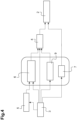
- the main elements of the module are schematized on the Figure 4 where we see that the battery 3 powers the satellite geo-positioning receiver 5, the inertial navigation unit 6, INS, the laser rangefinder 9, the camera 7, the calculator 4 and the restitution screen by the intermediate of the camera 7 which sends current to it in addition to the image data.
- the inertial navigation unit 6, INS, the laser rangefinder 9 and the camera 7 are grouped within an opto-mechanical harmonization zone schematized by a box framed on this Figure 4 .
- the data from the satellite geo-positioning receiver 5 are combined with those of the inertial navigation unit 6 then sent to the computer 4.
- the computer also receives data from the laser range finder 9. It is understood that the module can be configured differently for this which concerns data exchanges: the computer can directly and separately receive data from the satellite geo-positioning receiver 5, the inertial navigation unit 6 and the laser rangefinder 9 and ensure hybridization.
- module 1 is this time in the form of binoculars that can be attached to a rifle or other portable equipment.
- the satellite geo-positioning receiver 5, GNSS At the upper part of module 1 is arranged the satellite geo-positioning receiver 5, GNSS.
- the optical elements At the front of module 1, the optical elements are visible with the infrared camera 7 and the laser rangefinder 9 because their respective removable protective covers 19 have been opened.
- a control button 18 is accessible on the module1.
- modules are produced with INS in order to benefit from the advantages of the inertial unit but, in other versions, we can simply use instead of the INS, an attitude reference unit and cap, AHRS.
Landscapes
- Engineering & Computer Science (AREA)
- Remote Sensing (AREA)
- Physics & Mathematics (AREA)
- Radar, Positioning & Navigation (AREA)
- General Physics & Mathematics (AREA)
- General Engineering & Computer Science (AREA)
- Computer Networks & Wireless Communication (AREA)
- Optics & Photonics (AREA)
- Electromagnetism (AREA)
- Astronomy & Astrophysics (AREA)
- Multimedia (AREA)
- Theoretical Computer Science (AREA)
- Position Fixing By Use Of Radio Waves (AREA)
- Navigation (AREA)
Claims (11)
- Autonomes Modul (1) zum visuellen Anpeilen, das Informationen über die Position eines von einem Nutzer angepeilten Ziels erzeugt und dazu bestimmt ist, auf einer tragbaren Ausrüstung (11) installiert zu werden, um ein tragbares und autonomes System zum visuellen Anpeilen eines Ziels zu bilden, wobei die Informationen über die Position des Ziels mindestens die Richtung des Ziels sind, wobei das Modul- eine autonome Stromversorgung (3),- elektronische Schaltkreise (4) zum Steuern, Rechnen und Bilden einer Schnittstelle mit dem Nutzer,- einen Sensor zum Erfassen von Bewegungen mit einer Trägheitsnavigationszentrale INS (6), die die Position und die Richtung des Moduls liefert, oder mit einer Bezugszentrale für Basis und Richtung AHRS, die nur die Richtung liefert,- einen Empfänger für satellitengestützte Positionsbestimmung GNSS (5), der ermöglicht, die Modulposition in Echtzeit und durchgehend zu liefern und die Trägheitssensoren hybrid zu machen,- eine optronische Einheit, die eine Gesamtheit von optischen Sensoren vom Typ Fernglas (14) und/oder Kameras (7), die ermöglichen, das Modul visuell auf das angepeilte Ziel zu richten, und ein Telemeter (9), das ermöglicht, die Entfernung zwischen dem Ziel und dem Modul zu bestimmen, aufweist,aufweist,dadurch gekennzeichnet, daß der Bewegungssensor Kreisel und Beschleunigungsmesser aufweist und daß die Kreisel Kreisel mit Halbkugelresonanz HRG sind, die ermöglichen, die Nordrichtung autonom zu bestimmen, undwobei das Modul außerdem Mittel zum Umpositionieren auf der Grundlage von Winkel- oder Triangulationsmessungen verschiedener, für die optronische Einheit sichtbarer Bezugspunkte mit bekannten Positionen aufweist, für den Fall daß der Empfänger für satellitengestützte Positionsbestimmung GNSS nicht ermöglicht, die Position des Moduls zu liefern.
- Modul (1) gemäß Anspruch 1, dadurch gekennzeichnet, daß es außerdem ein Podometer aufweist und daß die Trägheitsnavigationszentrale INS oder die Bezugszentrale für Basis und Ausrichtung AHRS außerdem mit dem Podometer hybridisiert ist.
- Modul (1) gemäß Anspruch 1 oder Anspruch 2, dadurch gekennzeichnet, daß es außerdem eine Befestigungsvorrichtung (8) aufweist, die ermöglicht, das Modul auf der tragbaren Ausrüstung (11) zu befestigen, und daß die Befestigungsvorrichtung dazu ausgelegt ist, auf einer Befestigungsschiene der Ausrüstung befestigt zu werden.
- Modul (1) gemäß einem der Ansprüche 1 bis 3, dadurch gekennzeichnet, daß es ein optisches Fernrohr mit direkter Sicht des Nutzers und mindestens eine Zieldarstellungskamera, die Bilder erzeugt, aufweist, wobei die mindestens eine Kamera eine Darstellung des Ziels mindestens bei Tag ermöglicht.
- Modul (1) gemäß Anspruch 4, dadurch gekennzeichnet, daß die mindestens eine Kamera (7) außerdem eine Darstellung des Ziels bei Nacht ermöglicht.
- Modul (1) gemäß Anspruch 5, dadurch gekennzeichnet, daß das Modulentweder zwei Kameras, eine erste zur Zieldarstellung bei Tag und eine zweite zur Zieldarstellung bei Nacht, wobei die zweite Kamera aus den Kameras mit Lichtverstärkung und den nur für Infrarot ausgelegten Kameras ausgewählt ist,oder nur eine Kamera zur Zieldarstellung bei Tag in Kombination mit einer Zielbeleuchtung, die ermöglicht, das Ziel für dessen Darstellung bei Nacht zu beleuchten,oder eine einzige Kamera, die nur für Infrarot empfindlich ist, für eine Zieldarstellung bei Tag und bei Nachtaufweist
- Modul (1) gemäß einem der Ansprüche 1 bis 6, dadurch gekennzeichnet, daß es mindestens eine Kamera (7), die Bilder des angepeilten Ziels liefert, und mindestens eine Darstellungsvorrichtung (2), die ermöglicht, die besagten Bilder darzustellen aufweist, wobei die mindestens eine Darstellungsvorrichtung entweder im Modul integriert ist oder in einem Abstand zum Modul angeordnet ist.
- Modul (1) gemäß einem der Ansprüche 1 bis 7, dadurch gekennzeichnet, daß es eine drahtlose Datenübermittlungsvorrichtung (13) für die Übermittlung der Informationen über die Position des Ziels und, falls das Modul mindestens eine Kamera (7) aufweist, der Bilder des angepeilten Ziels aufweist.
- Modul (1) gemäß einem der Ansprüche 1 bis 8, dadurch gekennzeichnet, daß es einen Unsicherheitsgrad, der geringer als oder gleich 2 mrad rms ist, und einen Genauigkeitsgrad für die Position, der dem des Empfängers für satellitengestützte Positionsbestimmung GNSS (5) entspricht, hat.
- Modul (1) gemäß einem der Ansprüche 1 bis 9, dadurch gekennzeichnet, daß es ein Gewicht von weniger als fünf Kilogramm hat.
- System, das aus einem autonomen Modul (1) zum visuellen Anpeilen, das auf einer tragbaren Ausrüstung (11) befestigt ist, besteht,
dadurch gekennzeichnet, daß das Modul gemäß einem der Ansprüche 1 bis 10 ausgelegt ist und daß die tragbare Ausrüstung (11) eine tragbare Waffe ist, wobei die Waffe dazu ausgelegt ist, ein angepeiltes Ziel mindestens zu neutralisieren.
Applications Claiming Priority (2)
| Application Number | Priority Date | Filing Date | Title |
|---|---|---|---|
| FR1872006A FR3089283B1 (fr) | 2018-11-29 | 2018-11-29 | Module autonome optronique de pointage de cible géolocalisé pour système portable et système correspondant |
| PCT/EP2019/082992 WO2020109515A1 (fr) | 2018-11-29 | 2019-11-28 | Module autonome optronique de pointage de cible geolocalise pour systeme portable et systeme correspondant |
Publications (2)
| Publication Number | Publication Date |
|---|---|
| EP3887747A1 EP3887747A1 (de) | 2021-10-06 |
| EP3887747B1 true EP3887747B1 (de) | 2024-07-31 |
Family
ID=67185081
Family Applications (1)
| Application Number | Title | Priority Date | Filing Date |
|---|---|---|---|
| EP19809482.3A Active EP3887747B1 (de) | 2018-11-29 | 2019-11-28 | Autonomes optronisches modul zum zeigen auf ein geolokalisiertes ziel für ein tragbares system und entsprechendes system |
Country Status (4)
| Country | Link |
|---|---|
| US (1) | US20220042769A1 (de) |
| EP (1) | EP3887747B1 (de) |
| FR (1) | FR3089283B1 (de) |
| WO (1) | WO2020109515A1 (de) |
Families Citing this family (3)
| Publication number | Priority date | Publication date | Assignee | Title |
|---|---|---|---|---|
| FR3093794B1 (fr) * | 2019-03-14 | 2021-03-12 | Ixblue | Systeme passif d'amortissement de chocs pour un appareil de visee |
| US11821996B1 (en) * | 2019-11-12 | 2023-11-21 | Lockheed Martin Corporation | Outdoor entity and weapon tracking and orientation |
| FR3120132B1 (fr) * | 2021-02-19 | 2023-02-10 | Safran Electronics & Defense | Navigation lors d'une opération de leurrage d'un recepteur de signaux satellitaires |
Family Cites Families (16)
| Publication number | Priority date | Publication date | Assignee | Title |
|---|---|---|---|---|
| US4949089A (en) * | 1989-08-24 | 1990-08-14 | General Dynamics Corporation | Portable target locator system |
| CA2249474C (fr) | 1997-01-17 | 2006-02-21 | Bernard Alhadef | Dispositif apte a determiner la direction d'une cible dans un repere predefini |
| FR2758625B1 (fr) | 1997-01-17 | 1999-03-19 | Sofresud | Dispositif apte a determiner la direction d'une cible dans un repere predefini |
| US6834234B2 (en) * | 2000-11-22 | 2004-12-21 | Trimble Navigation, Limited | AINS land surveyor system with reprocessing, AINS-LSSRP |
| FR2824132B1 (fr) | 2001-04-27 | 2007-07-13 | France Etat | Dispositif, et procede associe, apte a determiner la direction d'une cible |
| FR2852405B3 (fr) | 2003-03-14 | 2005-06-03 | Dispositif et procede associe apte a determiner la direction d'une cible | |
| FR2890755B1 (fr) * | 2005-09-09 | 2007-12-28 | Thales Sa | Dispositif optique d'observation d'une cible, multifonction |
| US7518713B2 (en) * | 2005-11-08 | 2009-04-14 | Honeywell International Inc. | Passive-optical locator |
| US8275544B1 (en) * | 2005-11-21 | 2012-09-25 | Miltec Missiles & Space | Magnetically stabilized forward observation platform |
| FR2929700B1 (fr) | 2006-10-23 | 2016-02-05 | Sofresud | Dispositif decentralise d'autodefense comprenant un pointeur portable et mobile apte a assurer en urgence la defense rapprochee d'un navire ou d'une plate-forme en mer contre une menace de surface. |
| US20100027022A1 (en) * | 2008-07-29 | 2010-02-04 | Honeywell International Inc. | Fiber optic gyroscope |
| FR2942044B1 (fr) | 2009-02-10 | 2016-02-05 | Sofresud | Dispositif de securite consistant a mesurer la distance entre deux plateformes mobiles par techniques inertielle et radio electrique |
| US8378279B2 (en) * | 2009-11-23 | 2013-02-19 | Fraser-Volpe, Llc | Portable integrated laser optical target tracker |
| US20120059575A1 (en) * | 2010-02-05 | 2012-03-08 | Honeywell International Inc. | Target locator device and methods |
| FR3057656B1 (fr) | 2016-10-14 | 2019-04-05 | Sofresud | Dispositif visuel pour la designation d’objectifs et procede de designation d’objectif utilisant ledit dispositif |
| IL268505B2 (en) * | 2017-02-06 | 2024-09-01 | Sheltered Wings Inc D/B/A Vortex Optics | Viewing optic with an integrated display system |
-
2018
- 2018-11-29 FR FR1872006A patent/FR3089283B1/fr active Active
-
2019
- 2019-11-28 US US17/297,668 patent/US20220042769A1/en not_active Abandoned
- 2019-11-28 WO PCT/EP2019/082992 patent/WO2020109515A1/fr not_active Ceased
- 2019-11-28 EP EP19809482.3A patent/EP3887747B1/de active Active
Non-Patent Citations (1)
| Title |
|---|
| DELHAYE FABRICE: "HRG by SAFRAN: The game-changing technology", 2018 IEEE INTERNATIONAL SYMPOSIUM ON INERTIAL SENSORS AND SYSTEMS (INERTIAL), IEEE, 26 March 2018 (2018-03-26), pages 1 - 4, XP033339841, DOI: 10.1109/ISISS.2018.8358163 * |
Also Published As
| Publication number | Publication date |
|---|---|
| FR3089283B1 (fr) | 2021-03-12 |
| WO2020109515A1 (fr) | 2020-06-04 |
| EP3887747A1 (de) | 2021-10-06 |
| US20220042769A1 (en) | 2022-02-10 |
| FR3089283A1 (fr) | 2020-06-05 |
Similar Documents
| Publication | Publication Date | Title |
|---|---|---|
| US11187884B2 (en) | Viewing optic with an integrated display system | |
| US11480781B2 (en) | Viewing optic with direct active reticle targeting | |
| AU2010270410B2 (en) | Fire-control system | |
| EP3324147B1 (de) | Visuelle vorrichtung zur zielbestimmung, und bestimmungsverfahren von zielen, bei dem diese vorrichtung zum einsatz kommt | |
| EP2247910B1 (de) | Visier | |
| WO2020109515A1 (fr) | Module autonome optronique de pointage de cible geolocalise pour systeme portable et systeme correspondant | |
| CA3155671A1 (en) | Ballistic calculator hub | |
| EP3155358B1 (de) | System zum lenken von raketen für fahrzeuge und bewegliche ziele | |
| WO2004083767A2 (fr) | Dispositif de visee ou de pointage | |
| WO2024200477A1 (fr) | Système de téléopération | |
| CA2249474C (fr) | Dispositif apte a determiner la direction d'une cible dans un repere predefini | |
| FR2890755A1 (fr) | Dispositif optique d'observation d'une cible, multifonction |
Legal Events
| Date | Code | Title | Description |
|---|---|---|---|
| STAA | Information on the status of an ep patent application or granted ep patent |
Free format text: STATUS: UNKNOWN |
|
| STAA | Information on the status of an ep patent application or granted ep patent |
Free format text: STATUS: THE INTERNATIONAL PUBLICATION HAS BEEN MADE |
|
| PUAI | Public reference made under article 153(3) epc to a published international application that has entered the european phase |
Free format text: ORIGINAL CODE: 0009012 |
|
| STAA | Information on the status of an ep patent application or granted ep patent |
Free format text: STATUS: REQUEST FOR EXAMINATION WAS MADE |
|
| 17P | Request for examination filed |
Effective date: 20210518 |
|
| AK | Designated contracting states |
Kind code of ref document: A1 Designated state(s): AL AT BE BG CH CY CZ DE DK EE ES FI FR GB GR HR HU IE IS IT LI LT LU LV MC MK MT NL NO PL PT RO RS SE SI SK SM TR |
|
| DAV | Request for validation of the european patent (deleted) | ||
| DAX | Request for extension of the european patent (deleted) | ||
| STAA | Information on the status of an ep patent application or granted ep patent |
Free format text: STATUS: EXAMINATION IS IN PROGRESS |
|
| 17Q | First examination report despatched |
Effective date: 20230303 |
|
| RAP3 | Party data changed (applicant data changed or rights of an application transferred) |
Owner name: EXAIL |
|
| GRAP | Despatch of communication of intention to grant a patent |
Free format text: ORIGINAL CODE: EPIDOSNIGR1 |
|
| STAA | Information on the status of an ep patent application or granted ep patent |
Free format text: STATUS: GRANT OF PATENT IS INTENDED |
|
| INTG | Intention to grant announced |
Effective date: 20240410 |
|
| GRAS | Grant fee paid |
Free format text: ORIGINAL CODE: EPIDOSNIGR3 |
|
| GRAA | (expected) grant |
Free format text: ORIGINAL CODE: 0009210 |
|
| STAA | Information on the status of an ep patent application or granted ep patent |
Free format text: STATUS: THE PATENT HAS BEEN GRANTED |
|
| AK | Designated contracting states |
Kind code of ref document: B1 Designated state(s): AL AT BE BG CH CY CZ DE DK EE ES FI FR GB GR HR HU IE IS IT LI LT LU LV MC MK MT NL NO PL PT RO RS SE SI SK SM TR |
|
| P01 | Opt-out of the competence of the unified patent court (upc) registered |
Free format text: CASE NUMBER: APP_37276/2024 Effective date: 20240621 |
|
| REG | Reference to a national code |
Ref country code: CH Ref legal event code: EP Ref country code: GB Ref legal event code: FG4D Free format text: NOT ENGLISH |
|
| REG | Reference to a national code |
Ref country code: DE Ref legal event code: R096 Ref document number: 602019056205 Country of ref document: DE |
|
| REG | Reference to a national code |
Ref country code: IE Ref legal event code: FG4D Free format text: LANGUAGE OF EP DOCUMENT: FRENCH |
|
| PGFP | Annual fee paid to national office [announced via postgrant information from national office to epo] |
Ref country code: GB Payment date: 20240905 Year of fee payment: 6 |
|
| PGFP | Annual fee paid to national office [announced via postgrant information from national office to epo] |
Ref country code: FR Payment date: 20240813 Year of fee payment: 6 |
|
| REG | Reference to a national code |
Ref country code: LT Ref legal event code: MG9D |
|
| REG | Reference to a national code |
Ref country code: NL Ref legal event code: MP Effective date: 20240731 |
|
| PG25 | Lapsed in a contracting state [announced via postgrant information from national office to epo] |
Ref country code: PT Free format text: LAPSE BECAUSE OF FAILURE TO SUBMIT A TRANSLATION OF THE DESCRIPTION OR TO PAY THE FEE WITHIN THE PRESCRIBED TIME-LIMIT Effective date: 20241202 |
|
| REG | Reference to a national code |
Ref country code: AT Ref legal event code: MK05 Ref document number: 1708823 Country of ref document: AT Kind code of ref document: T Effective date: 20240731 |
|
| PG25 | Lapsed in a contracting state [announced via postgrant information from national office to epo] |
Ref country code: PT Free format text: LAPSE BECAUSE OF FAILURE TO SUBMIT A TRANSLATION OF THE DESCRIPTION OR TO PAY THE FEE WITHIN THE PRESCRIBED TIME-LIMIT Effective date: 20241202 |
|
| PGFP | Annual fee paid to national office [announced via postgrant information from national office to epo] |
Ref country code: DE Payment date: 20240814 Year of fee payment: 6 |
|
| PG25 | Lapsed in a contracting state [announced via postgrant information from national office to epo] |
Ref country code: NO Free format text: LAPSE BECAUSE OF FAILURE TO SUBMIT A TRANSLATION OF THE DESCRIPTION OR TO PAY THE FEE WITHIN THE PRESCRIBED TIME-LIMIT Effective date: 20241031 |
|
| PG25 | Lapsed in a contracting state [announced via postgrant information from national office to epo] |
Ref country code: NL Free format text: LAPSE BECAUSE OF FAILURE TO SUBMIT A TRANSLATION OF THE DESCRIPTION OR TO PAY THE FEE WITHIN THE PRESCRIBED TIME-LIMIT Effective date: 20240731 Ref country code: FI Free format text: LAPSE BECAUSE OF FAILURE TO SUBMIT A TRANSLATION OF THE DESCRIPTION OR TO PAY THE FEE WITHIN THE PRESCRIBED TIME-LIMIT Effective date: 20240731 Ref country code: GR Free format text: LAPSE BECAUSE OF FAILURE TO SUBMIT A TRANSLATION OF THE DESCRIPTION OR TO PAY THE FEE WITHIN THE PRESCRIBED TIME-LIMIT Effective date: 20241101 Ref country code: PL Free format text: LAPSE BECAUSE OF FAILURE TO SUBMIT A TRANSLATION OF THE DESCRIPTION OR TO PAY THE FEE WITHIN THE PRESCRIBED TIME-LIMIT Effective date: 20240731 |
|
| PG25 | Lapsed in a contracting state [announced via postgrant information from national office to epo] |
Ref country code: BG Free format text: LAPSE BECAUSE OF FAILURE TO SUBMIT A TRANSLATION OF THE DESCRIPTION OR TO PAY THE FEE WITHIN THE PRESCRIBED TIME-LIMIT Effective date: 20240731 |
|
| PG25 | Lapsed in a contracting state [announced via postgrant information from national office to epo] |
Ref country code: LV Free format text: LAPSE BECAUSE OF FAILURE TO SUBMIT A TRANSLATION OF THE DESCRIPTION OR TO PAY THE FEE WITHIN THE PRESCRIBED TIME-LIMIT Effective date: 20240731 |
|
| PG25 | Lapsed in a contracting state [announced via postgrant information from national office to epo] |
Ref country code: AT Free format text: LAPSE BECAUSE OF FAILURE TO SUBMIT A TRANSLATION OF THE DESCRIPTION OR TO PAY THE FEE WITHIN THE PRESCRIBED TIME-LIMIT Effective date: 20240731 Ref country code: IS Free format text: LAPSE BECAUSE OF FAILURE TO SUBMIT A TRANSLATION OF THE DESCRIPTION OR TO PAY THE FEE WITHIN THE PRESCRIBED TIME-LIMIT Effective date: 20241130 |
|
| PG25 | Lapsed in a contracting state [announced via postgrant information from national office to epo] |
Ref country code: HR Free format text: LAPSE BECAUSE OF FAILURE TO SUBMIT A TRANSLATION OF THE DESCRIPTION OR TO PAY THE FEE WITHIN THE PRESCRIBED TIME-LIMIT Effective date: 20240731 |
|
| PG25 | Lapsed in a contracting state [announced via postgrant information from national office to epo] |
Ref country code: ES Free format text: LAPSE BECAUSE OF FAILURE TO SUBMIT A TRANSLATION OF THE DESCRIPTION OR TO PAY THE FEE WITHIN THE PRESCRIBED TIME-LIMIT Effective date: 20240731 Ref country code: RS Free format text: LAPSE BECAUSE OF FAILURE TO SUBMIT A TRANSLATION OF THE DESCRIPTION OR TO PAY THE FEE WITHIN THE PRESCRIBED TIME-LIMIT Effective date: 20241031 |
|
| PG25 | Lapsed in a contracting state [announced via postgrant information from national office to epo] |
Ref country code: RS Free format text: LAPSE BECAUSE OF FAILURE TO SUBMIT A TRANSLATION OF THE DESCRIPTION OR TO PAY THE FEE WITHIN THE PRESCRIBED TIME-LIMIT Effective date: 20241031 Ref country code: PL Free format text: LAPSE BECAUSE OF FAILURE TO SUBMIT A TRANSLATION OF THE DESCRIPTION OR TO PAY THE FEE WITHIN THE PRESCRIBED TIME-LIMIT Effective date: 20240731 Ref country code: NO Free format text: LAPSE BECAUSE OF FAILURE TO SUBMIT A TRANSLATION OF THE DESCRIPTION OR TO PAY THE FEE WITHIN THE PRESCRIBED TIME-LIMIT Effective date: 20241031 Ref country code: NL Free format text: LAPSE BECAUSE OF FAILURE TO SUBMIT A TRANSLATION OF THE DESCRIPTION OR TO PAY THE FEE WITHIN THE PRESCRIBED TIME-LIMIT Effective date: 20240731 Ref country code: LV Free format text: LAPSE BECAUSE OF FAILURE TO SUBMIT A TRANSLATION OF THE DESCRIPTION OR TO PAY THE FEE WITHIN THE PRESCRIBED TIME-LIMIT Effective date: 20240731 Ref country code: IS Free format text: LAPSE BECAUSE OF FAILURE TO SUBMIT A TRANSLATION OF THE DESCRIPTION OR TO PAY THE FEE WITHIN THE PRESCRIBED TIME-LIMIT Effective date: 20241130 Ref country code: HR Free format text: LAPSE BECAUSE OF FAILURE TO SUBMIT A TRANSLATION OF THE DESCRIPTION OR TO PAY THE FEE WITHIN THE PRESCRIBED TIME-LIMIT Effective date: 20240731 Ref country code: GR Free format text: LAPSE BECAUSE OF FAILURE TO SUBMIT A TRANSLATION OF THE DESCRIPTION OR TO PAY THE FEE WITHIN THE PRESCRIBED TIME-LIMIT Effective date: 20241101 Ref country code: FI Free format text: LAPSE BECAUSE OF FAILURE TO SUBMIT A TRANSLATION OF THE DESCRIPTION OR TO PAY THE FEE WITHIN THE PRESCRIBED TIME-LIMIT Effective date: 20240731 Ref country code: ES Free format text: LAPSE BECAUSE OF FAILURE TO SUBMIT A TRANSLATION OF THE DESCRIPTION OR TO PAY THE FEE WITHIN THE PRESCRIBED TIME-LIMIT Effective date: 20240731 Ref country code: BG Free format text: LAPSE BECAUSE OF FAILURE TO SUBMIT A TRANSLATION OF THE DESCRIPTION OR TO PAY THE FEE WITHIN THE PRESCRIBED TIME-LIMIT Effective date: 20240731 Ref country code: AT Free format text: LAPSE BECAUSE OF FAILURE TO SUBMIT A TRANSLATION OF THE DESCRIPTION OR TO PAY THE FEE WITHIN THE PRESCRIBED TIME-LIMIT Effective date: 20240731 |
|
| PG25 | Lapsed in a contracting state [announced via postgrant information from national office to epo] |
Ref country code: SM Free format text: LAPSE BECAUSE OF FAILURE TO SUBMIT A TRANSLATION OF THE DESCRIPTION OR TO PAY THE FEE WITHIN THE PRESCRIBED TIME-LIMIT Effective date: 20240731 Ref country code: RO Free format text: LAPSE BECAUSE OF FAILURE TO SUBMIT A TRANSLATION OF THE DESCRIPTION OR TO PAY THE FEE WITHIN THE PRESCRIBED TIME-LIMIT Effective date: 20240731 Ref country code: DK Free format text: LAPSE BECAUSE OF FAILURE TO SUBMIT A TRANSLATION OF THE DESCRIPTION OR TO PAY THE FEE WITHIN THE PRESCRIBED TIME-LIMIT Effective date: 20240731 |
|
| PG25 | Lapsed in a contracting state [announced via postgrant information from national office to epo] |
Ref country code: EE Free format text: LAPSE BECAUSE OF FAILURE TO SUBMIT A TRANSLATION OF THE DESCRIPTION OR TO PAY THE FEE WITHIN THE PRESCRIBED TIME-LIMIT Effective date: 20240731 |
|
| PG25 | Lapsed in a contracting state [announced via postgrant information from national office to epo] |
Ref country code: CZ Free format text: LAPSE BECAUSE OF FAILURE TO SUBMIT A TRANSLATION OF THE DESCRIPTION OR TO PAY THE FEE WITHIN THE PRESCRIBED TIME-LIMIT Effective date: 20240731 |
|
| PG25 | Lapsed in a contracting state [announced via postgrant information from national office to epo] |
Ref country code: SK Free format text: LAPSE BECAUSE OF FAILURE TO SUBMIT A TRANSLATION OF THE DESCRIPTION OR TO PAY THE FEE WITHIN THE PRESCRIBED TIME-LIMIT Effective date: 20240731 Ref country code: IT Free format text: LAPSE BECAUSE OF FAILURE TO SUBMIT A TRANSLATION OF THE DESCRIPTION OR TO PAY THE FEE WITHIN THE PRESCRIBED TIME-LIMIT Effective date: 20240731 |
|
| REG | Reference to a national code |
Ref country code: DE Ref legal event code: R097 Ref document number: 602019056205 Country of ref document: DE |
|
| PLBE | No opposition filed within time limit |
Free format text: ORIGINAL CODE: 0009261 |
|
| STAA | Information on the status of an ep patent application or granted ep patent |
Free format text: STATUS: NO OPPOSITION FILED WITHIN TIME LIMIT |
|
| REG | Reference to a national code |
Ref country code: CH Ref legal event code: PL |
|
| PG25 | Lapsed in a contracting state [announced via postgrant information from national office to epo] |
Ref country code: MC Free format text: LAPSE BECAUSE OF FAILURE TO SUBMIT A TRANSLATION OF THE DESCRIPTION OR TO PAY THE FEE WITHIN THE PRESCRIBED TIME-LIMIT Effective date: 20240731 |
|
| 26N | No opposition filed |
Effective date: 20250501 |
|
| PG25 | Lapsed in a contracting state [announced via postgrant information from national office to epo] |
Ref country code: LU Free format text: LAPSE BECAUSE OF NON-PAYMENT OF DUE FEES Effective date: 20241128 |
|
| REG | Reference to a national code |
Ref country code: CH Ref legal event code: PL |
|
| PG25 | Lapsed in a contracting state [announced via postgrant information from national office to epo] |
Ref country code: CH Free format text: LAPSE BECAUSE OF NON-PAYMENT OF DUE FEES Effective date: 20241130 |
|
| REG | Reference to a national code |
Ref country code: BE Ref legal event code: MM Effective date: 20241130 |
|
| PG25 | Lapsed in a contracting state [announced via postgrant information from national office to epo] |
Ref country code: SE Free format text: LAPSE BECAUSE OF FAILURE TO SUBMIT A TRANSLATION OF THE DESCRIPTION OR TO PAY THE FEE WITHIN THE PRESCRIBED TIME-LIMIT Effective date: 20240731 |
|
| PG25 | Lapsed in a contracting state [announced via postgrant information from national office to epo] |
Ref country code: BE Free format text: LAPSE BECAUSE OF NON-PAYMENT OF DUE FEES Effective date: 20241130 |
|
| PG25 | Lapsed in a contracting state [announced via postgrant information from national office to epo] |
Ref country code: IE Free format text: LAPSE BECAUSE OF NON-PAYMENT OF DUE FEES Effective date: 20241128 |
|
| PG25 | Lapsed in a contracting state [announced via postgrant information from national office to epo] |
Ref country code: HU Free format text: LAPSE BECAUSE OF FAILURE TO SUBMIT A TRANSLATION OF THE DESCRIPTION OR TO PAY THE FEE WITHIN THE PRESCRIBED TIME-LIMIT; INVALID AB INITIO Effective date: 20191128 |
|
| PG25 | Lapsed in a contracting state [announced via postgrant information from national office to epo] |
Ref country code: CY Free format text: LAPSE BECAUSE OF FAILURE TO SUBMIT A TRANSLATION OF THE DESCRIPTION OR TO PAY THE FEE WITHIN THE PRESCRIBED TIME-LIMIT; INVALID AB INITIO Effective date: 20191128 |