EP3887682B1 - Rotierende kolbenstange für sprühflüssigkeitspumpe - Google Patents
Rotierende kolbenstange für sprühflüssigkeitspumpe Download PDFInfo
- Publication number
- EP3887682B1 EP3887682B1 EP19827909.3A EP19827909A EP3887682B1 EP 3887682 B1 EP3887682 B1 EP 3887682B1 EP 19827909 A EP19827909 A EP 19827909A EP 3887682 B1 EP3887682 B1 EP 3887682B1
- Authority
- EP
- European Patent Office
- Prior art keywords
- piston
- piston rod
- channel
- channels
- paint
- Prior art date
- Legal status (The legal status is an assumption and is not a legal conclusion. Google has not performed a legal analysis and makes no representation as to the accuracy of the status listed.)
- Active
Links
Images


Classifications
-
- F—MECHANICAL ENGINEERING; LIGHTING; HEATING; WEAPONS; BLASTING
- F04—POSITIVE - DISPLACEMENT MACHINES FOR LIQUIDS; PUMPS FOR LIQUIDS OR ELASTIC FLUIDS
- F04B—POSITIVE-DISPLACEMENT MACHINES FOR LIQUIDS; PUMPS
- F04B53/00—Component parts, details or accessories not provided for in, or of interest apart from, groups F04B1/00 - F04B23/00 or F04B39/00 - F04B47/00
- F04B53/14—Pistons, piston-rods or piston-rod connections
- F04B53/148—Pistons, piston-rods or piston-rod connections the piston being provided with channels which are coacting with the cylinder and are used as a distribution member for another piston-cylinder unit
-
- F—MECHANICAL ENGINEERING; LIGHTING; HEATING; WEAPONS; BLASTING
- F04—POSITIVE - DISPLACEMENT MACHINES FOR LIQUIDS; PUMPS FOR LIQUIDS OR ELASTIC FLUIDS
- F04B—POSITIVE-DISPLACEMENT MACHINES FOR LIQUIDS; PUMPS
- F04B53/00—Component parts, details or accessories not provided for in, or of interest apart from, groups F04B1/00 - F04B23/00 or F04B39/00 - F04B47/00
- F04B53/14—Pistons, piston-rods or piston-rod connections
- F04B53/144—Adaptation of piston-rods
-
- B—PERFORMING OPERATIONS; TRANSPORTING
- B05—SPRAYING OR ATOMISING IN GENERAL; APPLYING FLUENT MATERIALS TO SURFACES, IN GENERAL
- B05B—SPRAYING APPARATUS; ATOMISING APPARATUS; NOZZLES
- B05B9/00—Spraying apparatus for discharge of liquids or other fluent material, without essentially mixing with gas or vapour
- B05B9/03—Spraying apparatus for discharge of liquids or other fluent material, without essentially mixing with gas or vapour characterised by means for supplying liquid or other fluent material
- B05B9/04—Spraying apparatus for discharge of liquids or other fluent material, without essentially mixing with gas or vapour characterised by means for supplying liquid or other fluent material with pressurised or compressible container; with pump
- B05B9/0403—Spraying apparatus for discharge of liquids or other fluent material, without essentially mixing with gas or vapour characterised by means for supplying liquid or other fluent material with pressurised or compressible container; with pump with pumps for liquids or other fluent material
- B05B9/0413—Spraying apparatus for discharge of liquids or other fluent material, without essentially mixing with gas or vapour characterised by means for supplying liquid or other fluent material with pressurised or compressible container; with pump with pumps for liquids or other fluent material with reciprocating pumps, e.g. membrane pump, piston pump, bellow pump
-
- F—MECHANICAL ENGINEERING; LIGHTING; HEATING; WEAPONS; BLASTING
- F04—POSITIVE - DISPLACEMENT MACHINES FOR LIQUIDS; PUMPS FOR LIQUIDS OR ELASTIC FLUIDS
- F04B—POSITIVE-DISPLACEMENT MACHINES FOR LIQUIDS; PUMPS
- F04B15/00—Pumps adapted to handle specific fluids, e.g. by selection of specific materials for pumps or pump parts
- F04B15/02—Pumps adapted to handle specific fluids, e.g. by selection of specific materials for pumps or pump parts the fluids being viscous or non-homogeneous
Definitions
- FIG. 1 is an isometric view of fluid spraying system 1.
- FIG. 2 is a partially exploded view of fluid spraying system 1.
- FIGS. 1 and 2 will be discussed together.
- the fluid sprayer system 1 includes a frame 6.
- the frame 6 includes legs, in the embodiment shown.
- the frame 6 can additionally or alternatively include wheels or other ground-contacting supports.
- the frame 6 fully supports a main housing that contains a motor 4 and control 5.
- the motor 4 is mounted on and supported by the frame 6.
- the fluid spraying system 1 is man-portable and includes a handle 10 fixed to the frame 6 for picking up and carrying the fluid spray system 1 by hand. Some larger embodiments the fluid spraying system 1 may be wheeled by a person tilting and pushing the fluid spraying system 1.
- the control 5 delivers power to the motor 4.
- the motor 4 can be an electric brushless rotor stator motor, amongst other options. In other versions, the motor 4 could be a gas powered motor or a pneumatic or hydraulic powered motor, amongst other options. Generally, the motor 4 outputs rotational mechanical motion.
- the motor 4 turns drive 7, which in the illustrated embodiment includes drive parts 7A-7C.
- drive parts 7A-7C include various components such as gearing (7A), eccentric (7B), and a crank (7C) for turning rotational motion output by the motor 4 into linear reciprocating motion.
- the drive parts 7A-7C can include different components, such as a scotch yoke or other mechanism for converting rotation motion into linear reciprocating motion.
- the drive 7 reciprocates drive coupling 8.
- the drive coupling 8 connects with a top of a piston 15 of the pump 9 to reciprocate the piston 15 relative to a cylinder 12 of the pump 9.
- the pump 9 can be mounted on the frame 6 to brace or otherwise hold the cylinder 12 in place during piston 15 reciprocation.
- a rigid connection of the pump 9 to the frame 6 can be established by a ring clamping on a flange or the exterior of the cylinder of the pump 9, pinching the flange against a base of the fluid spraying system 1.
- the drive coupling 8 includes an attachment mechanism for connecting to an end (e.g., top) of the piston 15.
- One design of the attachment mechanism includes a slot formed in the drive coupling 8 for receiving and cradling a knob end of the piston 15.
- Other connection means are possible for similarly connecting the drive coupling 8 to the piston of the pump 9.
- the pump 9 takes paint in through the intake hose 2B.
- the end of the intake hose 2B can be submerged in a bucket filled with paint or other fluid to be sprayed.
- the pump 9 places the paint under pressure and outputs the paint through hose 2A to a spray gun 3.
- the spray gun 3 includes a trigger which can be actuated by hand to open an internal valve (not illustrated) and release the paint as an atomized spray.
- the piston 15 reciprocates within the cylinder 12. As shown, the piston 15 protrudes from a top of the pump 9, out from the cylinder 12 and the retaining nut 14. The portion of the piston 15 that is exposed includes a piston coupling 16.
- the piston coupling 16 in this embodiment is a head on the end of a neck.
- the piston coupling 16 can couple the piston 15 to the drive coupling 8 ( FIG. 2 ).
- the drive coupling 8 can include a socket that receives the head of the piston coupling 16 and cradles around the head about the neck of the piston coupling 16.
- the socket and cradle of the drive coupling 8 can be "U" shaped to allow the knob end of the piston coupling 16 to be slid in and out from only one side of the socket and cradle.
- the coupling thereby is engaged and disengaged only by lateral sliding (i.e. orthogonal to the reciprocation axis) for coupling and decoupling, without any other motion or actuation, but does not allow relative axial movement between the piston 15 and the drive coupling 8.
- the socket and cradle surround three of four lateral sides of the knob end of the piston coupling 16 and has a lateral opening on the fourth of the four lateral sides.
- the space within the cradle is narrower than the space within the socket but the cradle still allows the neck of the piston coupling 16, but not the wider knob portion of the piston coupling 16, to extend through and past the cradle.
- the interface can fix the piston 15 to the drive coupling 8 axially, such that up and down reciprocating motion of the drive coupling 8 correspondingly reciprocates the piston 15 along axis 41.
- the interface allows the piston 15 to rotate about the axis 41.
- the piston coupling 16 can rotate within the socket of the drive coupling 8.
- the head of the piston coupling 16 can slide laterally into and out of the socket of the drive coupling 8 to connect and disconnect the piston coupling 16 from the drive coupling 8.
- the cylinder 12 During reciprocation of the piston 15, the cylinder 12 is braced with respect to the main body of the paint spraying system 1, such as the frame 6 and the motor 4, so that the piston 15 reciprocates with respect to the cylinder 12. Due to the mounting of the pump 9 to the frame 6, the cylinder 12 does not rotate, reciprocate, or otherwise move unless when being dismounted for servicing (when spraying is not possible).
- FIG. 4 is a cross-sectional view of pump 9.
- FIG. 5 is a view of the pump 9 exploded along the piston axis 41.
- FIGS. 4 and 5 will be discussed together.
- Relative upstream and downstream directions are indicated by arrows in FIG. 4 , and such directions represent the general flow of paint through the pump 9 from the upstream direction to the downstream direction (the paint exiting the pump 9 through the pump outlet port 13).
- the piston 15 and cylinder 12 are each coaxial with piston axis 41.
- the piston 15 reciprocates along the piston axis 41 relative to the cylinder 12.
- the piston axis 41 is coaxial with the axis of the upstream and downstream directions.
- the piston axis 41 can be the axis along which the piston 15 reciprocates.
- the term radial refers to a direction orthogonal to the piston axis 41, such as any of the directions 360 degrees orthogonally about the piston axis 41. An example of a radial direction is shown by arrow R in
- the piston 15 includes a first seal 22.
- a first chamber 19, defined at least in part by the inner surface of the cylinder 12, is separated from a second chamber 26 by the first seal 22.
- the second chamber 26 is defined at least in part by the inner surface of the cylinder 12.
- the first seal 22 can be a piston seal in that it moves with the piston 15.
- the first seal 22 is fixed to the cylinder 12 and the piston 15 moves relative to the first seal 22.
- the first seal 22 dynamically seals between the exterior surface of the piston 15 and the opposing interior surface of the cylinder 12.
- the first seal 22 forces paint in the first chamber 19 to flow through the piston inlet 20 and ultimately out the channels 50 instead of the paint flowing around the piston 15 as the piston 15 reciprocates.
- the first seal 22 in this embodiment comprises stacked packing rings, which can be alternating polymer and leather rings (or all polymer rings), though it is understood that other configurations are possible.
- the first seal 22 can be a polymer sleeve, which may include one or more sealing flanges. Glands 30A, 30B bracket and capture the first seal 22.
- the first seal 22 is captured on the piston 15 and moves with the piston 15 relative to the circumferential inner surface of the cylinder 12, but in various other embodiments the first seal 22 is fixed to the inner surface of the cylinder 12 and the exterior circumferential surface of the piston 15 moves relative to the stationary first seal 22.
- the piston 15 has only one seal (whether a stack of rings or one element) that seals between the exterior annular surface of the manifold portion 51 of the piston 15 and the interior annular surface of the cylinder 12, which can be the first seal 22.
- a second seal 29 prevents paint in the second chamber 26 from leaking along the piston 15 or the inner surface of the cylinder 12 out of the top of the pump 9.
- the second seal 29 can be a throat seal.
- the second seal 29 also helps maintain output pressure in the second chamber 26.
- the second seal 29 is a dynamic seal and seals between the interior of the cylinder 12 and the exterior of the piston 15 even when these components reciprocate relative to each other.
- the second seal 29 can, in some examples, be identical to the first seal 22.
- the second seal 29 can comprise a stack of polymer and/or leather sealing rings captured between glands 30C, 30D.
- the glands 30C, 30D capture the second seal 29 and hold the second seal 29 to the cylinder 12. In this way, the piston 15 moves relative to the element(s) of the second seal 29.
- the second chamber 26 is generally tubular in shape and changes in volume as the piston 15 reciprocates.
- the lateral (or circumferential) walls of the second chamber 26 are defined by the outer surface of the piston rod 27 and the inner surface of the cylinder 12.
- the downstream end of the second chamber 26 is defined by the second seal 29, which remains static in position in this embodiment.
- the upstream end of the second chamber 26 is defined by the first seal 22, which axially moves during the piston 15 reciprocation cycle to alternately increase and decrease the volumes of the first and second chambers 19, 26 to move paint through the pump 9.
- the paint enters the pump 9 though the pump inlet port 17.
- the pump inlet port 17 is formed in the lower housing 11 in this embodiment.
- the lower housing 11 houses an inlet check valve 18.
- the inlet check valve 18 is a one-way valve which allows paint to flow in the downstream direction but blocks paint from flowing in the upstream direction.
- the inlet check valve 18 is shown as a ball and seat valve. As best seen in FIG. 5 , the inlet check valve 18 can be inside of a housing that fits within the lower housing 11. Generally, gravity pulls the ball onto the seat to close the inlet check valve 18. The flow of paint from the pump inlet port 17 in the downstream direction can overcome the weight of the ball to lift the ball off of the seat to open the valve.
- a spring may be used to maintain the ball on the seat until the spring force is overcome.
- Different valve designs or features are possible, such as a poppet, spring, or other type of inlet valve are possible for inlet check valve 18.
- the upstream movement of the piston 15 decreases the volume of the first chamber 19, increasing pressure in the first chamber 19 and also pushing the inlet check valve 18 closed.
- the first chamber 19 is defined by and within the cylinder 12.
- the first chamber 19 is in fluid communication with the piston 15.
- the piston 15 reciprocates to increase and decrease the volume of the first chamber 19. Specifically, on an upstroke, when the piston 15 moves in the downstream direction and which can be referred to as an intake stroke, the first chamber 19 expands, pulling paint from the inlet port 17 past the check valve 18 into the first chamber 19.
- On the downstroke when the piston 15 is moving in the upstream direction and which can be referred to as a pumping stroke, the volume in the first chamber 19 is decreased, thereby increasing the pressure within the first chamber 19. This action forces the paint, momentarily, in the upstream direction which closes inlet check valve 18.
- the paint in the first chamber 19 is forced through a piston inlet 20 formed in the piston 15.
- the paint flows into the interior of the piston 15.
- the piston 15 includes a piston face 21.
- the piston face 21 includes a conical inlet 20 to channel paint into the interior of the piston 15, although other piston face designs are possible.
- a piston check valve 24 is located within the piston 15.
- the piston check valve 24 moves with the piston 15 as the piston 15 reciprocates.
- the first chamber 19 is between the inlet check valve 18 and the piston check valve 24.
- the piston check valve 24 allows paint to flow in the downstream direction, evacuating from the first chamber 19, but prevents paint from flowing back in the upstream direction into the first chamber 19.
- Check valve 24 is shown as a ball and seat valve similar to the inlet check valve 18, but as earlier described, other valve designs and features are possible.
- the piston check valve 24 closes (e.g., ball engages seat) to prevent paint from flowing from an interior piston chamber 40 within the piston 15 back through the piston inlet 20.
- the piston check valve 24 e.g., unseats the ball
- the piston check valve 24 opens to allow paint from the piston inlet 20 to flow into the interior piston chamber 40 within the piston 15.
- paint flows through side bores 32.
- the side bores 32 are cylindrical passages that connect the interior piston chamber 40 to channels 50.
- the channels 50 as further described herein, are open and extend along the exterior of the piston 15.
- the piston 15 has only one fluid inlet (in this case piston inlet 20).
- the only fluid outlets of the piston 15 are the channels 50, each channel 50 being fed by a single respective side bore 32. Fluid being pumped can only enter the piston 15 through the piston inlet 20 and exit the piston 15 through the side bores 32 and channels 50.
- paint in the first chamber 19 is forced into the piston inlet 20 by the advancing piston face 21, past the piston check valve 24 into the interior piston chamber 40, through the side bores 32, leaves the piston 15 from the channels 50 into the second chamber 26, and through the pump outlet port 13.
- paint in the second chamber 26 is forced through the pump outlet port 13 on both the upstroke (due the piston check valve 24 being closed and the first seal 22 sealing with the inner surface of the cylinder 12 and pushing the paint in the second chamber 26 downstream) and the downstroke (due to the inlet check valve 18 being closed and the first seal 22 sealing with the inner surface of the cylinder 12 and reducing the volume of the first chamber 19 forcing the paint into the second chamber 26) due to the action of the piston check valve 24.
- the pump 9 is a double acting pump which promotes consistent cyclic output while minimizing output flow or pressure spikes.
- the pump outlet port 13 can, in some examples, be the only outlet for paint being expelled under pressure from the pump 9, absent failure of a seal.
- the piston 15 incudes piston rod 27.
- the piston rod 27 is cylindrical, and includes a cylindrical main body 46.
- the piston coupling 16 protrudes in the downstream direction relative to the main body 46.
- the main body 46 can have a constant outer diameter along its length.
- the main body 46 can extend from the downstream edge of a taper 52 to the upstream edge of the piston coupling 16.
- the second seal 29 contacts and seals with a circumferential exterior surface of the main body 46.
- the length of the piston rod 27, measured along the piston axis 41 ranges from 5.0 inches to 15.0 inches, although larger and smaller sizes may be possible.
- FIG. 6 shows a detailed view of the piston 15 with sealing components exploded with respect to the piston rod 27.
- the sealing components can further include, adjacent the gland 30A, a wiper ring 34 and a washer 35.
- the wiper ring 34 sweeps paint from the inner wall of the cylinder 12 along the first chamber 19 ( FIG. 4 ) as the piston 15 advances on the downstroke, but is separate from, and does not perform the same sealing function, as the first seal 22.
- the wiper ring 34 can be formed from polymer.
- the washer 35 can be formed from metal. The washer 35, wiper seal 60, gland 30A, first seal 22, and gland 30B fit on cylindrical recessed portion 38 of piston rod 27.
- the cylindrical recessed portion 38 has a smaller diameter than a manifold portion 51, with a shoulder 39 defining a wider annular portion of the piston rod 27 than the cylindrical recessed portion 38.
- the sealing components including the glands 30A and 30B, the first seal 22, the wiper ring 34, and/or the washer 35, can fit on and around the cylindrical recessed portion 38. These sealing components can be pinched between the shoulder 39 and the piston face 21 to retain these components on the cylindrical recessed portion 38.
- the piston face 21 screws into a threaded aperture on the upstream side of the piston rod 27 to form a second shoulder that captures the washer 35, wiper seal 60, gland 30 A, first seal 22, and/or gland 30B on the cylindrical recessed portion 38 of the manifold portion 51, and further captures the ball and the seat of the piston check valve 24 within the piston rod 27.
- the piston rod 27 includes a main body 48 and a piston manifold 51.
- the main body 48 can be solid metal.
- the main body 48 can be cylindrical, such that the exterior surface of the main body 48 can be cylindrical.
- the main body 48 can be cylindrical with uniform diameter from the downstream edge of the piston manifold 51 to the upstream edge of the piston coupling 16.
- the main body 48 can form the longest axial part of the piston 15.
- the majority of the length of the piston 15 along the piston axis 41 can be formed by only the main body 48, whereas the individual and/or combined lengths of the piston coupling 16, the piston manifold 51, and the piston face 21 is shorter than the main body 48.
- the main body 48 may be at least twice the length of the piston manifold 51.
- the exterior surface of the main body 48 is a sealing surface that dynamically seals with the second seal 29 (best seen in FIG. 4 ).
- the piston rod 27, as shown, is a unitary part.
- the piston rod 27 can be a single piece formed from metal, such as steel (e.g., stainless steel), with all features machined out from the single piece.
- the piston rod 27 could be formed by two separate pieces of metal joined together.
- the main body 48 and the manifold portion 51 may be formed separately and then threaded, welded, and/or press fit together.
- the piston rod 27 includes the recessed portion 38.
- the recessed portion 38 has a reduced diameter to accommodate the sealing components as previously described.
- the recessed portion 38 portion ends in the downstream direction at the shoulder 39.
- the shoulder 39 can be an expansion in the diameter of the piston rod 27 relative the recessed portion 38.
- the shoulder 39 serves as a stop to prevent the sealing components, such as the gland 30B, from moving past the shoulder 39 in the downstream direction along the piston rod 27.
- the piston rod 27 includes a manifold portion 51.
- the upstream end of the manifold portion 51 is defined by the shoulder 39.
- paint is routed from a single channel inside the piston rod 27 (e.g., through the piston chamber 40) and out of the piston rod 27 via multiple channels 50.
- the channels 50 are limited to the manifold portion 51.
- the channels 50 do not extend along the recessed portion 38 or the main body 48.
- the channels 50 are disposed radially outward relative to the main body 48. In some embodiments, the entirety of each of the channels 50 is radially outward from the main body 48.
- the deepest part of the channel 50 (e.g., the lateral center of the channel 50) is at the same radial position (e.g., radial distance from piston axis 41) as the exterior surface of the main body 48.
- the manifold portion 51 has a greater diameter than the rest of the piston rod 27 with respect to the axis 41.
- the manifold portion 51 has a greater diameter than the main body 48 and the recessed portion 38.
- the shoulder 39 forms the upstream edge of the manifold portion 51 while the downstream edge of the transition 52 forms the downstream edge of the manifold portion 51.
- While four side bores 32 and four channels 50 are shown herein along the piston rod 27, there could instead be a single piston bore 32 respectively connecting with a single channel 50, or a pair of side bores 32 connecting with a pair of channels 50, or three side bores 32 respectively connecting with three channels 50, or greater than four side bores 32 respectively fluidly connecting with greater than four channels 50.
- the side bores 32 can be evenly arrayed about the piston axis 41 of the piston 15.
- the channels 50 can be evenly arrayed about the piston axis 41 of the piston 15.
- the channels 50 can be evenly arrayed about the circumference of the piston 15.
- the downstream end of the manifold portion 51 is defined by the end of the transition 52.
- the transition 52 includes an annular (i.e. entirely about the piston rod 27) tapering of the diameter of the piston rod 27, and particularly the diameter of the manifold portion 51.
- the transition 52 can have a consistent slope (in the upstream-to-downstream direction) transitioning diameters of annular portions of the piston rod 27. The slope can be linear or curved upstream-to-downstream.
- the transition 52 reduces the diameter of the piston rod 27 from the wider exterior surface 56 of the manifold portion 51 to the narrower exterior surface of the main body 46. As shown, the transition 52 decreases in diameter in the downstream direction.
- the transition 52 is shown as a taper, the decrease in diameter could instead be more abrupt, such as by having the same flat annular profile of the shoulder 39 forming transition 52.
- the channels 50 do not extend downstream of the transition 52.
- the transition 52 terminates the channels 50 in the downstream direction being that the channels 50 are depressions formed into the larger-diameter manifold portion 51 and the transition 52 reduces the diameter of the piston rod 27 to a greater depth than the depth of the channels 50.
- the channels 50 direct the flow of paint exiting the piston rod 27, and the manifold portion 51 in particular, in orientations that generate a rotational moment about the piston 15 to rotate the piston during reciprocation.
- the manifold portion 51 includes an exterior surface 56.
- the exterior surface 56 is cylindrical except for the interruptions of the channels 50.
- the upstream edge of the exterior surface 56 is the shoulder 39.
- the downstream edge of the exterior surface 56 is the upstream edge of the transition 52.
- the exterior surface 56 of the manifold portion 51 is separated from the cylindrical interior surface of the cylinder 12 by piston-cylinder space 36.
- the radial distance between the exterior surface 56 of the manifold portion 51 and the cylindrical interior surface of the cylinder 12 may range from 0.03 - 0.07 inches (about 0.76 - 1.78 millimeters) depending on the embodiment, although larger and smaller radial separation distances are possible.
- the radial separation difference between the walls defining the channels 50 (particularly the bottom of the channels 50) and the interior surface of the cylinder 12 are greater than along the exterior surface 56, thus providing more radial space for the flow of paint within the channels 50 along the piston rod 27 as compared to the radial space between the exterior surface 56 of the manifold portion 51 and the cylindrical interior surface of cylinder 12.
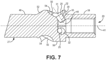
- FIG. 7 shows a cross-sectional view of the manifold portion 51 along the piston axis 41.
- the piston chamber 40 is coaxial with the piston axis 41.
- the manifold portion 51 includes a plurality of side bores 32 that branch from a piston chamber 40 formed through the axial core of the manifold portion 51.
- the side bores 32 fluidly connect the piston chamber 40 with the channels 50, respectively.
- the side bores 32 are formed (e.g., machined) through the metal that forms the manifold portion 51. Paint flowing through the manifold portion 51 enters through the piston inlet 20 and travels past the piston check valve 24 ( FIG. 4 ) then flows through the piston chamber 40 and then through the side bores 32, ultimately exiting the piston 15 from the channels 50.
- Each side bore 32 extends coaxially along a respective side port axis 55. In being coaxial with the side bore axis 55, each side bore 32 is angled relative to the piston axis 41. Such angling of the side bores 32 direct the paint in the downstream direction as the paint exits the side bores 32. As such, the paint is not ejected from the side bore axis 55 in a purely radial direction relative to the piston axis 41, or in a purely parallel direction relative to the piston axis 41. Instead, the side bores 32 direct each jet of exiting paint in a downstream direction along the side port axis 55. The angling of the side bores 32 in the downstream direction directs the exiting paint jets toward the pump outlet port 13 in the cylinder 12 to facilitate efficient flow of paint out of the pump 9.
- FIG. 8 shows a cross-sectional view aligned with the piston axis 41.
- the side bores 32 and the channels 50 are evenly arrayed about the circumference of the piston 15.
- the piston chamber 40 has a greater cross sectional area than any one of the side bores 32.
- the side bores 32 are the only downstream outlets of the piston chamber 40.
- the piston chamber 40 is not circular along its entire length along the piston axis 41.
- the side bore axes 55 are offset with respect to the piston axis 41. As such, the side bore axes 55 do not intersect the piston axis 41.
- the side bores 32 direct jets of paint along the side bore axis 55. Being coaxial with the side bore axes 55, each jet of paint has a tangential component with respect to the circumference of the piston 15.
- the center of mass of the piston 15 is along the piston axis 41.
- the side angling of the side bores 32 ejects the paint along vectors (aligned with the reciprocation axes 41) so as to impart a moment on piston 15, torqueing the piston 15.
- the side bores 32 are orientated to expel paint in generally the same circumferential direction about the piston 15.
- any moments imparted on piston 15 by the jets are cumulative.
- the cumulative moment can cause piston 15 to rotate circumferentially about the piston axis 41 in a rotation direction 44 during reciprocation of the piston 15 when fluid is pumped.
- the limited separation distance of the piston-cylinder space 36 FIG. 4
- channels 50 are provided to route the flow of paint within the piston 15 to exits for which the ejection jets have greater clearance for developing, as further discussed herein.
- FIG. 9 is a detailed side view of the upstream end of the piston rod 27.
- FIG. 10 is a detailed side view of the upstream end of the piston rod 27, the view coaxial with the side bore axis 55 of one of the side bores 32.
- FIG. 11 is a detailed side view of the upstream end of the piston rod 27, the view aligned with one of the channels 50 (the aligned channel identified as 50* in FIG. 11 ).
- FIGS. 9-11 will be discussed together.
- FIGS. 9-11 show the manifold portion 51 and the channels 50 formed in the manifold portion 51.
- Each channel 50 is defined by a channel wall 54.
- the channel wall 54 is formed from the metal that forms the manifold portion 51, and can be the metal that forms the rest of the piston rod 27.
- Each channel 50 can begin at the termination of the side bore 32 at the outer cylindrical end 25 of the side bore 32.
- Each channel 50 can end at downstream lip 53.
- the downstream lip 53 of the channel 50 can be the downstream-most ridge defining an edge of the channel 50. In that way, the downstream lip 53 can represent the downstream termination of a channel 50.
- the downstream lip 53 can be the part of the piston rod 27 where the transition 52 reduces the diameter of the piston rod 27 to be below the depth of the channel 50, terminating the channel 50.
- each channel 50 is defined by lateral channel edges 59.
- the lateral channel edges 59 are adjacent the cylindrical exterior surface 56, and represent the point at which the depression of the channel 50 interrupts the cylindrical exterior surface 56 of the manifold portion 51.
- the channel 50 has the same radial depth along its entire length. In some embodiments, as shown herein, the radial depth of the channel 50 can vary along the length of the channel 50.
- the channel 50 includes a bowl 31.
- the bowl 31 is a partial hemispherical depression (with respect to the exterior surface 56) in the piston manifold 51.
- the bowl 31 can be aligned with the side bore 32 with respect to the piston axis 41.
- the bowl 31 can be coaxially aligned with the side bore axis 55 ( FIG. 7 ) (e.g., the side bore axis 55 can be aligned with the apex of the hemispherical shape of the bowl 31).
- the bowl 31 is the upstream-most portion of each channel 50.
- the only portion of the channel 50 having a consistent depth along the length of the channel 50 is located on the downstream side of the bowl 31.
- the walls of the channel 50, including the bowl 31, on the upstream side of the channel 50 with respect to the outer cylindrical end 25 of the side bore 32 are sloped between the outer cylindrical end 25 and the exterior surface 56, such that no portion of the channel 50 on the upstream side of the channel 50 has a consistent depth.
- the paint exiting the outer cylindrical end 25 of the side bore 32 can either directly exit the channel 50 or can travel along the channel axis 57.
- the paint exiting the outer cylindrical end 25 of the side bore 32 cannot flow along a consistent depth channel in the upstream direction due to the bowl 31.
- the channels 50 only extend in the downstream direction, and do not extend in the upstream direction, with respect to the outer cylindrical end 25 of the side bores 32.
- the downstream lip 53 forms the downstream terminus of the channel 50.
- the downstream lip 53 is formed by the transition 52.
- the downstream lip 53 is formed as the decreased or decreasing radius of the transition 52 intersects with the channel walls 54, thus forming the downstream terminus of the channel 50.
- the lateral channel edge 59 defines the boundary of the channels 50 and the exterior surface 56.
- Two lateral channel edges 59 extend in parallel for each channel 50.
- the lateral channel edges 59 extend only along the cylindrical surface 56 and stop at the upstream end of the transition 51, the lateral channel edges 59 giving way to the downstream lip 53 as the boundary of the channel 50 and the transition 52.
- the downstream lip 53 is located downstream of the upstream edge of the transition 52.
- the downstream lip 53 is not located upstream of the upstream edge of the transition 53.
- the lateral channel edge 59 is located upstream of the upstream edge of the transition 52.
- the lateral channel edge 59 is not located downstream of the upstream edge of the transition 52.
- the depth of the channel 50 can stay the same along most, or all, of the length of the channel 50.
- the depth of the channel 50 decreases along the transition 52.
- the depth of the channel 50 decreases along the downstream lip 53.
- the channels 50 can each have a length, from the outer cylindrical ends 25 of the side bores 32 to the downstream lips 53, of 0.4 - 1.5 inches (about 10.1 - 38.1 millimeters), although shorter and greater lengths are possible.
- each channel 50 is arrayed about the piston axis 41.
- the channels 50 can be evenly arrayed about the piston axis 41.
- each channel 50 may only extend around a quarter of the circumference of the manifold portion 51.
- each channel 41 may extend less than half way around the circumference of the manifold portion 51.
- each channel 41 may not extend or otherwise wrap entirely around the circumference of the manifold portion 51.
- each channel 50 includes a channel axis 57.
- Each channel 50 is coaxial with its channel axis 57. While each channel 50 is open along its entire length (e.g., in the manner of a trench, not being fully enclosed) and therefore not forming an entire cylindrical shape, the rounded channel wall 54 of each channel 50 would form a cylindrical shape that is coaxial with the channel axis 57 were the channel wall 54 fully annular and not open.
- Each channel 50 intersects with the side bore axis 55. In particular, the channel axis 57 intersects with the side bore axis 55.
- each channel 50 is straight. Each channel 50 is straight along its entire length. Each channel 50 can be straight despite its radial depth changing along its length. Each channel 50 can be straight from the outer cylindrical end 25 of the side bore 32 (or the bowl 31) to its downstream lip 53. In this embodiment, each channel 50 does not bend along its entire length. In this embodiment, each channel 50 does not curve along its entire length. Each channel 50 can remain aligned with its channel axis 57 along its entire length. The straightness of the channel 50 can reduce hydraulic resistance and provide a consistent flow path, as opposed to a curved channel length, for supporting jets exiting the channels 50 from the openings 53.
- the channels 50 do not extend parallel with the reciprocation axis 41.
- the channels 50 are angled with respect to the piston axis 41.
- the channels 50 are orientated tangentially, or substantially tangentially, with respect to the circumference of the piston rod 27.
- the channels 50 are offset with respect to the piston axis 41, and further the center of mass of the piston 15.
- the channel axes 57 do not extend parallel with the piston axis 41.
- the channel axes 57 are angled with respect to the piston axis 41.
- the channel axes 57 are orientated tangentially, or substantially tangentially, with respect to the circumference of the piston rod 27.
- the channel axes 57 are offset with respect to the piston axis 41, and further the center of mass of the piston 15.
- Each channel 50 directs a jet of paint that exits the channel 50 from the downstream lip 53.
- the jet of paint can be along the channel axis 57.
- the jet of paint can be aligned with the channel axis 57.
- the jet of paint can be coaxial with the channel axis 57.
- the offset angle of the channel 50 results in the jet of paint exiting the downstream lip 53 of the channel 50 imparting a moment on the piston 15 about the piston axis 41.
- the cumulative moments of the jets from the channels 50, arrayed about the piston 15, rotates the piston 15 with each ejection of paint during each reciprocation cycle of the piston 15.
- Expelling paint to generate rotational moments about the piston 50 incrementally rotates the piston 15 about the piston axis 41 with each reciprocation cycle such that piston 15 makes one complete 360 degree rotation over multiple reciprocation cycles.
- the rotational force is provided solely by the ejection of paint from the side bores 32 and/or openings 53 of the channel 50.
- the cylinder 12 is fixed and does not rotate, and as such the piston 15 rotates relative to the cylinder 12 during pumping of paint.
- the first seal 22, fixed to the manifold portion 51 rotates with the manifold portion 51 and rotates relative to the cylinder 12.
- the exterior surface of the main body 48 rotates relative to the second seal 29 ( FIG. 4 ).
- Rotating piston 15 relative to cylinder 12 provides advantages.
- the interfacing surfaces experience wear and erosion due to the tight interface fit at the interfacing surfaces, particularly between the first seal 22, the second seal 29, the cylinder 12, and the main body 48.
- Grit and other solids in the fluid can become disposed between the interfacing surfaces, thereby causing accelerated wear on the interfacing surfaces.
- the grit and other solids can cause seals 22, 29 to wear asymmetrically.
- Asymmetrical wear leads to greater penetration of paint between the interfacing surfaces, leading to imbalanced reciprocation of piston 15 and potential creation of a bypass channel past seals 22, 29 that allows the paint to flow through pressurizing seals 22, 29.
- Continuously rotating piston 15 while piston 15 reciprocates within cylinder 12 induces symmetrical wear of dynamic interfacing sealing surfaces.
- rotating piston 15 distributes the wear caused by the grit and other solids about the circumference of the interfacing surfaces. Rotating of the piston 15 thereby minimizes the likelihood of a bypass channel forming, preventing seals 22 and/or 29 from failing prematurely. Symmetrical wear also prevents imbalance of the piston 15, as symmetrical wear of seals 22 and/or 29 causes the imparted forces to be evenly distributed.
- the side bores 32 may not be offset from the piston axis 41, such that ejection of paint from the side bores 32 itself does not create a moment in the piston 15 about the piston axis 41 to rotate the piston 15.
- the side bores 32 may generate little or no rotational moment. Rather, the rotational moment that rotates the piston 15 is generated by ejection of the paint from the openings 53 at the end of the channels 50. In some embodiments, most or all of the rotational moment that rotates the piston 15 is generated by ejection of the paint from the openings 53 at the end of the channels 50.
Landscapes
- Engineering & Computer Science (AREA)
- Mechanical Engineering (AREA)
- General Engineering & Computer Science (AREA)
- Reciprocating Pumps (AREA)
- Details Of Reciprocating Pumps (AREA)
Claims (15)
- Kolbenstange (27) für ein Farbsprühsystem, die sich entlang einer Hin- und Herbewegungsachse (41) länglich erstreckt, wobei die Kolbenstange umfasst:eine innere Kolbenkammer;einen oder mehrere Kanäle (50), die an einer Außenseite der Kolbenstange ausgebildet sind; undeine oder mehrere Seitenbohrungen (32), die sich durch die Kolbenstange erstrecken und die innere Kolbenkammer jeweils mit dem einen oder den mehreren Kanälen in Strömungsverbindung setzen, wobei jede der einen oder mehreren Seitenbohrungen einem jeweiligen Kanal zugeordnet ist und sich koaxial entlang einer jeweiligen Seitenbohrungsachse (55) erstreckt, die relativ zu der Hin- und Herbewegungsachse gewinkelt ist, um Farbe in eine stromabwärtige Richtung und in den jeweiligen Kanal zu lenken, wenn die Farbe aus der Seitenbohrung austritt;wobei sich jeder Kanal des einen oder der mehreren Kanäle mindestens teilweise axial erstreckt und entlang einer Länge des Kanals offen ist;wobei jeder des einen oder der mehreren Kanäle in Bezug auf die Hin- und Herbewegungsachse winkelversetzt ist;wobei der aus jedem des einen oder der mehreren Kanäle ausgestoßene Farbfluss während des Pumpens ein Rotationsmoment auf die Kolbenstange ausübt.
- Kolbenstange nach Anspruch 1, wobei jeder des einen oder der mehreren Kanäle (50) eine stromabwärtige Lippe (53) aufweist, und wobei der Farbfluss aus jedem Kanal an der stromabwärtigen Lippe ausgestoßen wird.
- Kolbenstange nach Anspruch 2, wobei die stromabwärtige Lippe (53) einen stromabwärtigen Endpunkt des Kanals definiert.
- Kolbenstange nach Anspruch 3, wobei ein stromabwärtiger Endpunkt jedes Kanals durch einen Übergang gebildet wird, an dem ein Durchmesser der Kolbenstange von einem breiteren Durchmesser zu einem engeren Durchmesser übergeht.
- Kolbenstange nach Anspruch 1, wobei das Rotationsmoment die Kolbenstange während des Pumpens um die Hin- und Herbewegungsachse dreht.
- Kolbenstange nach Anspruch 1, wobei sich jeder des einen oder der mehreren Kanäle (50) gerade entlang der Länge des Kanals erstreckt.
- Kolbenstange nach einem der Ansprüche 1 - 5, wobei sich jeder des einen oder der mehreren Kanäle (50) gerade erstreckt und sich entlang der Länge des Kanals weder krümmt noch biegt.
- Kolbenstange nach einem der Ansprüche 1 - 6, wobei zusätzlich zu dem aus jedem des einen oder der mehreren Kanäle ausgestoßenen Farbfluss der aus jeder der einen oder der mehreren Seitenbohrungen (32) ausgestoßene Farbfluss während des Pumpens ein Rotationsmoment auf die Kolbenstange ausübt.
- Kolbenstange nach einem der Ansprüche 1 - 3, 5 und 6, wobei ein stromabwärtiger Endpunkt jedes des einen oder der mehreren Kanäle (50) in einem an der Kolbenstange ausgebildeten Übergang endet, und wobei ein Durchmesser der Kolbenstange von einem stromaufwärtigen Ende des Übergangs zu einem stromabwärtigen Ende des Übergangs entlang des Übergangs kleiner wird.
- Kolbenstange nach einem der Ansprüche 1 - 6, wobei mindestens drei seitliche Bohrungen (32) gleichmäßig um die Kolbenstange herum angeordnet sind und mindestens drei Kanäle (50) gleichmäßig um die Kolbenstange herum angeordnet sind, wobei die mindestens drei Seitenbohrungen jeweils mit den mindestens drei Kanälen in Strömungsverbindung stehen.
- Kolbenstange nach einem der Ansprüche 1 - 6, wobei eine erste Dichtung (22) an einer Außenseite der Kolbenstange aufgenommen ist.
- Kolbenstange nach Anspruch 1, wobei eine Schale (31) an einem Schnittpunkt zwischen einer Seitenbohrung der einen oder der mehreren Seitenbohrungen und einem Kanal des einen oder der mehreren Kanäle ausgebildet ist.
- Kolbenstange nach Anspruch 1, wobei:die Kolbenstange ein erstes Ende, einen Hauptkörper und ein zweites Ende hat;sich das erste und das zweite Ende an gegenüberliegenden Enden des Hauptkörpers befinden;der Hauptkörper (46) eine längliche zylindrische Oberfläche aufweist;das erste Ende eine Kolbenkupplung (16) aufweist; unddas zweite Ende die innere Kolbenkammer, die eine oder mehreren Seitenbohrungen (32) und den einen oder die mehreren Kanäle (50) aufweist.
- Kolbenstange nach Anspruch 13, wobei jeder Kanal des einen oder der mehreren Kanäle eine quer zur Bohrungsachse (55) verlaufende Kanalachse (57) aufweist.
- Kolbenstange nach Anspruch 14, wobei sich jeder Kanal gerade entlang der Kanalachse erstreckt.
Applications Claiming Priority (2)
| Application Number | Priority Date | Filing Date | Title |
|---|---|---|---|
| US201862771698P | 2018-11-27 | 2018-11-27 | |
| PCT/US2019/063299 WO2020112809A1 (en) | 2018-11-27 | 2019-11-26 | Rotating piston rod for spray fluid pump |
Publications (2)
| Publication Number | Publication Date |
|---|---|
| EP3887682A1 EP3887682A1 (de) | 2021-10-06 |
| EP3887682B1 true EP3887682B1 (de) | 2024-06-12 |
Family
ID=69005848
Family Applications (1)
| Application Number | Title | Priority Date | Filing Date |
|---|---|---|---|
| EP19827909.3A Active EP3887682B1 (de) | 2018-11-27 | 2019-11-26 | Rotierende kolbenstange für sprühflüssigkeitspumpe |
Country Status (4)
| Country | Link |
|---|---|
| US (1) | US12116997B2 (de) |
| EP (1) | EP3887682B1 (de) |
| CN (1) | CN113167270B (de) |
| WO (1) | WO2020112809A1 (de) |
Families Citing this family (3)
| Publication number | Priority date | Publication date | Assignee | Title |
|---|---|---|---|---|
| US12172176B2 (en) * | 2020-10-01 | 2024-12-24 | Graco Minnesota Inc. | Battery powered fluid sprayer |
| US11971022B2 (en) | 2021-03-17 | 2024-04-30 | Graco Minnesota Inc. | System for dispensing abrasive material |
| US12097524B2 (en) | 2021-07-20 | 2024-09-24 | Graco Minnesota Inc. | Fluid sprayer with covered battery |
Family Cites Families (51)
| Publication number | Priority date | Publication date | Assignee | Title |
|---|---|---|---|---|
| US518490A (en) | 1894-04-17 | Piston for artesian or oil wells | ||
| US1026873A (en) | 1911-02-28 | 1912-05-21 | William S Locke | Plunger. |
| US1201543A (en) | 1915-09-04 | 1916-10-17 | John J Becker | Valve for deep-well pumps. |
| US1278769A (en) | 1916-08-28 | 1918-09-10 | John E Shutt | Plunger for pumps. |
| US1966694A (en) | 1930-06-17 | 1934-07-17 | Vaudet Paul Laxare | Pump |
| US2394371A (en) | 1945-03-21 | 1946-02-05 | Frances L Davis | Pump |
| US2674506A (en) | 1953-02-10 | 1954-04-06 | Richard B Dow | Rotatable piston |
| US3057300A (en) | 1958-03-06 | 1962-10-09 | Otmar M Ulbing | Pump and metering apparatus |
| US3106138A (en) | 1960-06-27 | 1963-10-08 | Hans Toma | Piston type hydrostatic power units |
| US3170298A (en) | 1962-11-09 | 1965-02-23 | Gen Motors Corp | Method and apparatus for compensating for tolerance stack limits in a power brake unit |
| US3172338A (en) | 1963-05-27 | 1965-03-09 | Sandex Inc | Hydropneumatic actuator |
| US3351316A (en) | 1965-01-15 | 1967-11-07 | Donald E Lewis | Pilot operated piston valve |
| US3489093A (en) | 1968-09-11 | 1970-01-13 | Cav Ltd | Liquid fuel pumping apparatus |
| GB1560093A (en) | 1975-07-11 | 1980-01-30 | Richter P A | Fluid operated device |
| US4089229A (en) | 1976-08-02 | 1978-05-16 | James Leonard Geraci | Rotary torque actuator |
| US4209285A (en) | 1977-11-09 | 1980-06-24 | The Richardson Company | Unitary pump packing |
| US4479759A (en) | 1979-12-13 | 1984-10-30 | Vernon Zeitz | Valveless, positive displacement pump |
| US4785997A (en) | 1987-11-02 | 1988-11-22 | Durotech Co. | Hydraulic motor for use with airless paint sprayer system |
| US4804109A (en) | 1987-12-14 | 1989-02-14 | Vanderjagt John A | Returnable container system |
| US5211611A (en) | 1989-08-01 | 1993-05-18 | American Power Equipment Company | Planocentric drive mechanism |
| US5228842A (en) | 1991-07-30 | 1993-07-20 | Wagner Spray Tech Corporation | Quick-change fluid section for piston-type paint pumps |
| DE4307327A1 (de) | 1993-03-09 | 1994-09-15 | Hartbecke Uwe | Bohrlochförderpumpe |
| CN2206361Y (zh) | 1994-08-20 | 1995-08-30 | 孙德盛 | 自动搅沙抽油泵 |
| US5660534A (en) * | 1995-10-30 | 1997-08-26 | Snow; Jerry M. | Rotating plunger for sucker rod pump |
| US5740718A (en) | 1996-10-17 | 1998-04-21 | Binks Manufacturing Company | Modular piston rod assembly with integrated high-wear components |
| US6283148B1 (en) | 1996-12-17 | 2001-09-04 | Flowmore Systems, Inc. | Standing valve with a curved fin |
| US6212999B1 (en) | 1998-01-02 | 2001-04-10 | Graco Minnesota Inc. | Automatic throat packing torque clip |
| US6244226B1 (en) | 1999-08-06 | 2001-06-12 | Caterpillar Inc. | Free piston internal combustion engine with rotating piston |
| US6435846B1 (en) | 1999-10-22 | 2002-08-20 | Wagner Spray Tech Corporation | Piston pump having housing with a pump housing and a pump assembly drive housing formed therein |
| DE10053574B4 (de) | 2000-10-28 | 2005-07-28 | Danfoss Compressors Gmbh | Kolbenverdichter, insbesondere hermetisch gekapselter Kältemittelverdichter |
| US6481987B2 (en) | 2001-03-19 | 2002-11-19 | Michael Brent Ford | Travelling valve for a pumping apparatus |
| CN2687377Y (zh) | 2004-01-07 | 2005-03-23 | 中国石化胜利油田有限公司采油工艺研究院 | 旋流刮砂抽油泵 |
| CN2727450Y (zh) | 2004-09-15 | 2005-09-21 | 玉门石油管理局 | 整筒管式防砂抽油泵 |
| US7713035B2 (en) | 2004-10-15 | 2010-05-11 | Michael Brant Ford | Cyclonic debris removal device and method for a pumping apparatus |
| US7162944B2 (en) | 2005-04-19 | 2007-01-16 | Bret Allen Britz | Continuous reciprocating linear motion device |
| DE102006028638A1 (de) | 2006-06-22 | 2008-01-03 | Robert Bosch Gmbh | Kolbenpumpe |
| US7428923B2 (en) | 2006-11-14 | 2008-09-30 | Ford Michael B | Top plunger adapter |
| US20080217565A1 (en) | 2007-03-09 | 2008-09-11 | Michael Brent Ford | Sucker rod pump with improved ball containment valve cage |
| US7878767B2 (en) * | 2007-09-12 | 2011-02-01 | Michael Brent Ford | Cyclonic, debris removing valve and method |
| US8360756B2 (en) * | 2008-10-31 | 2013-01-29 | Michael Brent Ford | Valve rod guide with cyclonic debris removal |
| US9188120B2 (en) * | 2009-05-22 | 2015-11-17 | Michael Brent Ford | Cyclonic debris evacuation apparatus and method for a pump |
| US8561813B2 (en) | 2009-05-22 | 2013-10-22 | Michael Brent Ford | Cyclonic debris evacuation apparatus and method for a pump |
| US8662857B2 (en) | 2010-01-29 | 2014-03-04 | Wagner Spray Tech Corporation | Pressure control for a fluid sprayer |
| CN103115034B (zh) | 2011-11-16 | 2015-07-29 | 基准精密工业(惠州)有限公司 | 旋转气缸 |
| US9341183B1 (en) | 2012-04-05 | 2016-05-17 | Don V. Carruth | Plunger adapter with sandwiper for downhole pump |
| EP3042441B1 (de) | 2013-09-04 | 2020-12-23 | Graco Minnesota Inc. | Lüftergekühlter motor mit freilaufendem lüfter |
| CN107002665B (zh) | 2014-12-30 | 2019-11-29 | 固瑞克明尼苏达有限公司 | 轴向往复泵上的一体式安装系统 |
| CN204511866U (zh) | 2015-02-13 | 2015-07-29 | 中国人民武装警察部队工程大学 | 一种柱塞泵用减磨柱塞 |
| AU2016277738B2 (en) | 2015-12-30 | 2021-07-22 | Graco Minnesota Inc. | Fluted piston components for pumps |
| JP6590217B2 (ja) | 2016-06-20 | 2019-10-16 | Smc株式会社 | シリンダ装置 |
| BR102018003284B1 (pt) | 2017-02-21 | 2021-07-20 | Graco Minnesota Inc. | Haste de pistão para uma bomba, bomba, pulverizador, e, método para substituir uma luva de desgaste |
-
2019
- 2019-11-26 WO PCT/US2019/063299 patent/WO2020112809A1/en not_active Ceased
- 2019-11-26 CN CN201980077912.XA patent/CN113167270B/zh active Active
- 2019-11-26 US US17/297,321 patent/US12116997B2/en active Active
- 2019-11-26 EP EP19827909.3A patent/EP3887682B1/de active Active
Also Published As
| Publication number | Publication date |
|---|---|
| US20220025882A1 (en) | 2022-01-27 |
| US12116997B2 (en) | 2024-10-15 |
| CN113167270B (zh) | 2023-06-16 |
| WO2020112809A1 (en) | 2020-06-04 |
| EP3887682A1 (de) | 2021-10-06 |
| CN113167270A (zh) | 2021-07-23 |
Similar Documents
| Publication | Publication Date | Title |
|---|---|---|
| US10859162B2 (en) | Rotating piston for pumps | |
| EP3887682B1 (de) | Rotierende kolbenstange für sprühflüssigkeitspumpe | |
| US8771799B2 (en) | Liquid delivery system | |
| AU2012328773B2 (en) | Sprayer fluid supply with collapsible liner | |
| US12313061B2 (en) | Fluid dispensing system having a piston rod and wear sleeve | |
| US10487827B2 (en) | High pressure paint pump | |
| CN102421533B (zh) | 用于流体泵送机构的摆动组件 | |
| CN108360800B (zh) | 具有滑动泵安装件的材料喷涂器 | |
| US20240288110A1 (en) | Portable fluid sprayer having a tube dampener | |
| GB2290352A (en) | Pumps |
Legal Events
| Date | Code | Title | Description |
|---|---|---|---|
| STAA | Information on the status of an ep patent application or granted ep patent |
Free format text: STATUS: UNKNOWN |
|
| STAA | Information on the status of an ep patent application or granted ep patent |
Free format text: STATUS: THE INTERNATIONAL PUBLICATION HAS BEEN MADE |
|
| PUAI | Public reference made under article 153(3) epc to a published international application that has entered the european phase |
Free format text: ORIGINAL CODE: 0009012 |
|
| STAA | Information on the status of an ep patent application or granted ep patent |
Free format text: STATUS: REQUEST FOR EXAMINATION WAS MADE |
|
| 17P | Request for examination filed |
Effective date: 20210628 |
|
| AK | Designated contracting states |
Kind code of ref document: A1 Designated state(s): AL AT BE BG CH CY CZ DE DK EE ES FI FR GB GR HR HU IE IS IT LI LT LU LV MC MK MT NL NO PL PT RO RS SE SI SK SM TR |
|
| DAV | Request for validation of the european patent (deleted) | ||
| DAX | Request for extension of the european patent (deleted) | ||
| STAA | Information on the status of an ep patent application or granted ep patent |
Free format text: STATUS: EXAMINATION IS IN PROGRESS |
|
| 17Q | First examination report despatched |
Effective date: 20221122 |
|
| GRAP | Despatch of communication of intention to grant a patent |
Free format text: ORIGINAL CODE: EPIDOSNIGR1 |
|
| STAA | Information on the status of an ep patent application or granted ep patent |
Free format text: STATUS: GRANT OF PATENT IS INTENDED |
|
| RIC1 | Information provided on ipc code assigned before grant |
Ipc: B05B 9/04 20060101ALI20231212BHEP Ipc: F04B 15/02 20060101ALI20231212BHEP Ipc: F04B 53/14 20060101AFI20231212BHEP |
|
| INTG | Intention to grant announced |
Effective date: 20240108 |
|
| GRAS | Grant fee paid |
Free format text: ORIGINAL CODE: EPIDOSNIGR3 |
|
| GRAA | (expected) grant |
Free format text: ORIGINAL CODE: 0009210 |
|
| STAA | Information on the status of an ep patent application or granted ep patent |
Free format text: STATUS: THE PATENT HAS BEEN GRANTED |
|
| P01 | Opt-out of the competence of the unified patent court (upc) registered |
Effective date: 20240424 |
|
| AK | Designated contracting states |
Kind code of ref document: B1 Designated state(s): AL AT BE BG CH CY CZ DE DK EE ES FI FR GB GR HR HU IE IS IT LI LT LU LV MC MK MT NL NO PL PT RO RS SE SI SK SM TR |
|
| REG | Reference to a national code |
Ref country code: GB Ref legal event code: FG4D |
|
| REG | Reference to a national code |
Ref country code: CH Ref legal event code: EP |
|
| REG | Reference to a national code |
Ref country code: IE Ref legal event code: FG4D |
|
| REG | Reference to a national code |
Ref country code: DE Ref legal event code: R096 Ref document number: 602019053665 Country of ref document: DE |
|
| PG25 | Lapsed in a contracting state [announced via postgrant information from national office to epo] |
Ref country code: BG Free format text: LAPSE BECAUSE OF FAILURE TO SUBMIT A TRANSLATION OF THE DESCRIPTION OR TO PAY THE FEE WITHIN THE PRESCRIBED TIME-LIMIT Effective date: 20240612 |
|
| PG25 | Lapsed in a contracting state [announced via postgrant information from national office to epo] |
Ref country code: HR Free format text: LAPSE BECAUSE OF FAILURE TO SUBMIT A TRANSLATION OF THE DESCRIPTION OR TO PAY THE FEE WITHIN THE PRESCRIBED TIME-LIMIT Effective date: 20240612 Ref country code: FI Free format text: LAPSE BECAUSE OF FAILURE TO SUBMIT A TRANSLATION OF THE DESCRIPTION OR TO PAY THE FEE WITHIN THE PRESCRIBED TIME-LIMIT Effective date: 20240612 |
|
| REG | Reference to a national code |
Ref country code: LT Ref legal event code: MG9D |
|
| PG25 | Lapsed in a contracting state [announced via postgrant information from national office to epo] |
Ref country code: GR Free format text: LAPSE BECAUSE OF FAILURE TO SUBMIT A TRANSLATION OF THE DESCRIPTION OR TO PAY THE FEE WITHIN THE PRESCRIBED TIME-LIMIT Effective date: 20240913 |
|
| REG | Reference to a national code |
Ref country code: NL Ref legal event code: MP Effective date: 20240612 |
|
| PG25 | Lapsed in a contracting state [announced via postgrant information from national office to epo] |
Ref country code: ES Free format text: LAPSE BECAUSE OF FAILURE TO SUBMIT A TRANSLATION OF THE DESCRIPTION OR TO PAY THE FEE WITHIN THE PRESCRIBED TIME-LIMIT Effective date: 20240612 |
|
| PG25 | Lapsed in a contracting state [announced via postgrant information from national office to epo] |
Ref country code: LV Free format text: LAPSE BECAUSE OF FAILURE TO SUBMIT A TRANSLATION OF THE DESCRIPTION OR TO PAY THE FEE WITHIN THE PRESCRIBED TIME-LIMIT Effective date: 20240612 |
|
| PG25 | Lapsed in a contracting state [announced via postgrant information from national office to epo] |
Ref country code: NO Free format text: LAPSE BECAUSE OF FAILURE TO SUBMIT A TRANSLATION OF THE DESCRIPTION OR TO PAY THE FEE WITHIN THE PRESCRIBED TIME-LIMIT Effective date: 20240912 Ref country code: LV Free format text: LAPSE BECAUSE OF FAILURE TO SUBMIT A TRANSLATION OF THE DESCRIPTION OR TO PAY THE FEE WITHIN THE PRESCRIBED TIME-LIMIT Effective date: 20240612 Ref country code: HR Free format text: LAPSE BECAUSE OF FAILURE TO SUBMIT A TRANSLATION OF THE DESCRIPTION OR TO PAY THE FEE WITHIN THE PRESCRIBED TIME-LIMIT Effective date: 20240612 Ref country code: GR Free format text: LAPSE BECAUSE OF FAILURE TO SUBMIT A TRANSLATION OF THE DESCRIPTION OR TO PAY THE FEE WITHIN THE PRESCRIBED TIME-LIMIT Effective date: 20240913 Ref country code: FI Free format text: LAPSE BECAUSE OF FAILURE TO SUBMIT A TRANSLATION OF THE DESCRIPTION OR TO PAY THE FEE WITHIN THE PRESCRIBED TIME-LIMIT Effective date: 20240612 Ref country code: ES Free format text: LAPSE BECAUSE OF FAILURE TO SUBMIT A TRANSLATION OF THE DESCRIPTION OR TO PAY THE FEE WITHIN THE PRESCRIBED TIME-LIMIT Effective date: 20240612 Ref country code: BG Free format text: LAPSE BECAUSE OF FAILURE TO SUBMIT A TRANSLATION OF THE DESCRIPTION OR TO PAY THE FEE WITHIN THE PRESCRIBED TIME-LIMIT Effective date: 20240612 Ref country code: RS Free format text: LAPSE BECAUSE OF FAILURE TO SUBMIT A TRANSLATION OF THE DESCRIPTION OR TO PAY THE FEE WITHIN THE PRESCRIBED TIME-LIMIT Effective date: 20240912 |
|
| PG25 | Lapsed in a contracting state [announced via postgrant information from national office to epo] |
Ref country code: NL Free format text: LAPSE BECAUSE OF FAILURE TO SUBMIT A TRANSLATION OF THE DESCRIPTION OR TO PAY THE FEE WITHIN THE PRESCRIBED TIME-LIMIT Effective date: 20240612 |
|
| REG | Reference to a national code |
Ref country code: AT Ref legal event code: MK05 Ref document number: 1694477 Country of ref document: AT Kind code of ref document: T Effective date: 20240612 |
|
| PG25 | Lapsed in a contracting state [announced via postgrant information from national office to epo] |
Ref country code: NL Free format text: LAPSE BECAUSE OF FAILURE TO SUBMIT A TRANSLATION OF THE DESCRIPTION OR TO PAY THE FEE WITHIN THE PRESCRIBED TIME-LIMIT Effective date: 20240612 |
|
| PG25 | Lapsed in a contracting state [announced via postgrant information from national office to epo] |
Ref country code: PT Free format text: LAPSE BECAUSE OF FAILURE TO SUBMIT A TRANSLATION OF THE DESCRIPTION OR TO PAY THE FEE WITHIN THE PRESCRIBED TIME-LIMIT Effective date: 20241014 |
|
| PG25 | Lapsed in a contracting state [announced via postgrant information from national office to epo] |
Ref country code: PT Free format text: LAPSE BECAUSE OF FAILURE TO SUBMIT A TRANSLATION OF THE DESCRIPTION OR TO PAY THE FEE WITHIN THE PRESCRIBED TIME-LIMIT Effective date: 20241014 |
|
| PG25 | Lapsed in a contracting state [announced via postgrant information from national office to epo] |
Ref country code: PL Free format text: LAPSE BECAUSE OF FAILURE TO SUBMIT A TRANSLATION OF THE DESCRIPTION OR TO PAY THE FEE WITHIN THE PRESCRIBED TIME-LIMIT Effective date: 20240612 |
|
| PG25 | Lapsed in a contracting state [announced via postgrant information from national office to epo] |
Ref country code: EE Free format text: LAPSE BECAUSE OF FAILURE TO SUBMIT A TRANSLATION OF THE DESCRIPTION OR TO PAY THE FEE WITHIN THE PRESCRIBED TIME-LIMIT Effective date: 20240612 |
|
| PG25 | Lapsed in a contracting state [announced via postgrant information from national office to epo] |
Ref country code: AT Free format text: LAPSE BECAUSE OF FAILURE TO SUBMIT A TRANSLATION OF THE DESCRIPTION OR TO PAY THE FEE WITHIN THE PRESCRIBED TIME-LIMIT Effective date: 20240612 Ref country code: IS Free format text: LAPSE BECAUSE OF FAILURE TO SUBMIT A TRANSLATION OF THE DESCRIPTION OR TO PAY THE FEE WITHIN THE PRESCRIBED TIME-LIMIT Effective date: 20241012 |
|
| PG25 | Lapsed in a contracting state [announced via postgrant information from national office to epo] |
Ref country code: CZ Free format text: LAPSE BECAUSE OF FAILURE TO SUBMIT A TRANSLATION OF THE DESCRIPTION OR TO PAY THE FEE WITHIN THE PRESCRIBED TIME-LIMIT Effective date: 20240612 |
|
| PG25 | Lapsed in a contracting state [announced via postgrant information from national office to epo] |
Ref country code: SK Free format text: LAPSE BECAUSE OF FAILURE TO SUBMIT A TRANSLATION OF THE DESCRIPTION OR TO PAY THE FEE WITHIN THE PRESCRIBED TIME-LIMIT Effective date: 20240612 Ref country code: RO Free format text: LAPSE BECAUSE OF FAILURE TO SUBMIT A TRANSLATION OF THE DESCRIPTION OR TO PAY THE FEE WITHIN THE PRESCRIBED TIME-LIMIT Effective date: 20240612 |
|
| PG25 | Lapsed in a contracting state [announced via postgrant information from national office to epo] |
Ref country code: SM Free format text: LAPSE BECAUSE OF FAILURE TO SUBMIT A TRANSLATION OF THE DESCRIPTION OR TO PAY THE FEE WITHIN THE PRESCRIBED TIME-LIMIT Effective date: 20240612 |
|
| PG25 | Lapsed in a contracting state [announced via postgrant information from national office to epo] |
Ref country code: SM Free format text: LAPSE BECAUSE OF FAILURE TO SUBMIT A TRANSLATION OF THE DESCRIPTION OR TO PAY THE FEE WITHIN THE PRESCRIBED TIME-LIMIT Effective date: 20240612 Ref country code: SK Free format text: LAPSE BECAUSE OF FAILURE TO SUBMIT A TRANSLATION OF THE DESCRIPTION OR TO PAY THE FEE WITHIN THE PRESCRIBED TIME-LIMIT Effective date: 20240612 Ref country code: RO Free format text: LAPSE BECAUSE OF FAILURE TO SUBMIT A TRANSLATION OF THE DESCRIPTION OR TO PAY THE FEE WITHIN THE PRESCRIBED TIME-LIMIT Effective date: 20240612 Ref country code: PL Free format text: LAPSE BECAUSE OF FAILURE TO SUBMIT A TRANSLATION OF THE DESCRIPTION OR TO PAY THE FEE WITHIN THE PRESCRIBED TIME-LIMIT Effective date: 20240612 Ref country code: IS Free format text: LAPSE BECAUSE OF FAILURE TO SUBMIT A TRANSLATION OF THE DESCRIPTION OR TO PAY THE FEE WITHIN THE PRESCRIBED TIME-LIMIT Effective date: 20241012 Ref country code: EE Free format text: LAPSE BECAUSE OF FAILURE TO SUBMIT A TRANSLATION OF THE DESCRIPTION OR TO PAY THE FEE WITHIN THE PRESCRIBED TIME-LIMIT Effective date: 20240612 Ref country code: CZ Free format text: LAPSE BECAUSE OF FAILURE TO SUBMIT A TRANSLATION OF THE DESCRIPTION OR TO PAY THE FEE WITHIN THE PRESCRIBED TIME-LIMIT Effective date: 20240612 Ref country code: AT Free format text: LAPSE BECAUSE OF FAILURE TO SUBMIT A TRANSLATION OF THE DESCRIPTION OR TO PAY THE FEE WITHIN THE PRESCRIBED TIME-LIMIT Effective date: 20240612 |
|
| PG25 | Lapsed in a contracting state [announced via postgrant information from national office to epo] |
Ref country code: IT Free format text: LAPSE BECAUSE OF FAILURE TO SUBMIT A TRANSLATION OF THE DESCRIPTION OR TO PAY THE FEE WITHIN THE PRESCRIBED TIME-LIMIT Effective date: 20240612 |
|
| REG | Reference to a national code |
Ref country code: DE Ref legal event code: R097 Ref document number: 602019053665 Country of ref document: DE |
|
| PG25 | Lapsed in a contracting state [announced via postgrant information from national office to epo] |
Ref country code: DK Free format text: LAPSE BECAUSE OF FAILURE TO SUBMIT A TRANSLATION OF THE DESCRIPTION OR TO PAY THE FEE WITHIN THE PRESCRIBED TIME-LIMIT Effective date: 20240612 |
|
| PLBE | No opposition filed within time limit |
Free format text: ORIGINAL CODE: 0009261 |
|
| STAA | Information on the status of an ep patent application or granted ep patent |
Free format text: STATUS: NO OPPOSITION FILED WITHIN TIME LIMIT |
|
| 26N | No opposition filed |
Effective date: 20250313 |
|
| REG | Reference to a national code |
Ref country code: CH Ref legal event code: PL |
|
| PG25 | Lapsed in a contracting state [announced via postgrant information from national office to epo] |
Ref country code: MC Free format text: LAPSE BECAUSE OF FAILURE TO SUBMIT A TRANSLATION OF THE DESCRIPTION OR TO PAY THE FEE WITHIN THE PRESCRIBED TIME-LIMIT Effective date: 20240612 |
|
| PG25 | Lapsed in a contracting state [announced via postgrant information from national office to epo] |
Ref country code: LU Free format text: LAPSE BECAUSE OF NON-PAYMENT OF DUE FEES Effective date: 20241126 |
|
| REG | Reference to a national code |
Ref country code: CH Ref legal event code: PL |
|
| PG25 | Lapsed in a contracting state [announced via postgrant information from national office to epo] |
Ref country code: CH Free format text: LAPSE BECAUSE OF NON-PAYMENT OF DUE FEES Effective date: 20241130 |
|
| REG | Reference to a national code |
Ref country code: BE Ref legal event code: MM Effective date: 20241130 |
|
| PG25 | Lapsed in a contracting state [announced via postgrant information from national office to epo] |
Ref country code: SE Free format text: LAPSE BECAUSE OF FAILURE TO SUBMIT A TRANSLATION OF THE DESCRIPTION OR TO PAY THE FEE WITHIN THE PRESCRIBED TIME-LIMIT Effective date: 20240612 |
|
| PG25 | Lapsed in a contracting state [announced via postgrant information from national office to epo] |
Ref country code: BE Free format text: LAPSE BECAUSE OF NON-PAYMENT OF DUE FEES Effective date: 20241130 |
|
| PG25 | Lapsed in a contracting state [announced via postgrant information from national office to epo] |
Ref country code: IE Free format text: LAPSE BECAUSE OF NON-PAYMENT OF DUE FEES Effective date: 20241126 |
|
| PGFP | Annual fee paid to national office [announced via postgrant information from national office to epo] |
Ref country code: DE Payment date: 20251128 Year of fee payment: 7 |
|
| PGFP | Annual fee paid to national office [announced via postgrant information from national office to epo] |
Ref country code: GB Payment date: 20251127 Year of fee payment: 7 |
|
| PGFP | Annual fee paid to national office [announced via postgrant information from national office to epo] |
Ref country code: FR Payment date: 20251125 Year of fee payment: 7 |