EP3887665B1 - System and method for on-board catalytic upgrading of hydrocarbon fuels - Google Patents
System and method for on-board catalytic upgrading of hydrocarbon fuels Download PDFInfo
- Publication number
- EP3887665B1 EP3887665B1 EP20703125.3A EP20703125A EP3887665B1 EP 3887665 B1 EP3887665 B1 EP 3887665B1 EP 20703125 A EP20703125 A EP 20703125A EP 3887665 B1 EP3887665 B1 EP 3887665B1
- Authority
- EP
- European Patent Office
- Prior art keywords
- fuel
- hydrocarbon
- reformed
- oxidizing gas
- subsystem
- Prior art date
- Legal status (The legal status is an assumption and is not a legal conclusion. Google has not performed a legal analysis and makes no representation as to the accuracy of the status listed.)
- Active
Links
Images

Classifications
-
- F—MECHANICAL ENGINEERING; LIGHTING; HEATING; WEAPONS; BLASTING
- F02—COMBUSTION ENGINES; HOT-GAS OR COMBUSTION-PRODUCT ENGINE PLANTS
- F02M—SUPPLYING COMBUSTION ENGINES IN GENERAL WITH COMBUSTIBLE MIXTURES OR CONSTITUENTS THEREOF
- F02M37/00—Apparatus or systems for feeding liquid fuel from storage containers to carburettors or fuel-injection apparatus; Arrangements for purifying liquid fuel specially adapted for, or arranged on, internal-combustion engines
- F02M37/0047—Layout or arrangement of systems for feeding fuel
- F02M37/0064—Layout or arrangement of systems for feeding fuel for engines being fed with multiple fuels or fuels having special properties, e.g. bio-fuels; varying the fuel composition
-
- C—CHEMISTRY; METALLURGY
- C10—PETROLEUM, GAS OR COKE INDUSTRIES; TECHNICAL GASES CONTAINING CARBON MONOXIDE; FUELS; LUBRICANTS; PEAT
- C10L—FUELS NOT OTHERWISE PROVIDED FOR; NATURAL GAS; SYNTHETIC NATURAL GAS OBTAINED BY PROCESSES NOT COVERED BY SUBCLASSES C10G OR C10K; LIQUIFIED PETROLEUM GAS; USE OF ADDITIVES TO FUELS OR FIRES; FIRE-LIGHTERS
- C10L1/00—Liquid carbonaceous fuels
- C10L1/04—Liquid carbonaceous fuels essentially based on blends of hydrocarbons
- C10L1/06—Liquid carbonaceous fuels essentially based on blends of hydrocarbons for spark ignition
-
- C—CHEMISTRY; METALLURGY
- C10—PETROLEUM, GAS OR COKE INDUSTRIES; TECHNICAL GASES CONTAINING CARBON MONOXIDE; FUELS; LUBRICANTS; PEAT
- C10L—FUELS NOT OTHERWISE PROVIDED FOR; NATURAL GAS; SYNTHETIC NATURAL GAS OBTAINED BY PROCESSES NOT COVERED BY SUBCLASSES C10G OR C10K; LIQUIFIED PETROLEUM GAS; USE OF ADDITIVES TO FUELS OR FIRES; FIRE-LIGHTERS
- C10L10/00—Use of additives to fuels or fires for particular purposes
- C10L10/12—Use of additives to fuels or fires for particular purposes for improving the cetane number
-
- F—MECHANICAL ENGINEERING; LIGHTING; HEATING; WEAPONS; BLASTING
- F02—COMBUSTION ENGINES; HOT-GAS OR COMBUSTION-PRODUCT ENGINE PLANTS
- F02D—CONTROLLING COMBUSTION ENGINES
- F02D19/00—Controlling engines characterised by their use of non-liquid fuels, pluralities of fuels, or non-fuel substances added to the combustible mixtures
- F02D19/06—Controlling engines characterised by their use of non-liquid fuels, pluralities of fuels, or non-fuel substances added to the combustible mixtures peculiar to engines working with pluralities of fuels, e.g. alternatively with light and heavy fuel oil, other than engines indifferent to the fuel consumed
- F02D19/0602—Control of components of the fuel supply system
- F02D19/0607—Control of components of the fuel supply system to adjust the fuel mass or volume flow
-
- F—MECHANICAL ENGINEERING; LIGHTING; HEATING; WEAPONS; BLASTING
- F02—COMBUSTION ENGINES; HOT-GAS OR COMBUSTION-PRODUCT ENGINE PLANTS
- F02D—CONTROLLING COMBUSTION ENGINES
- F02D19/00—Controlling engines characterised by their use of non-liquid fuels, pluralities of fuels, or non-fuel substances added to the combustible mixtures
- F02D19/06—Controlling engines characterised by their use of non-liquid fuels, pluralities of fuels, or non-fuel substances added to the combustible mixtures peculiar to engines working with pluralities of fuels, e.g. alternatively with light and heavy fuel oil, other than engines indifferent to the fuel consumed
- F02D19/0639—Controlling engines characterised by their use of non-liquid fuels, pluralities of fuels, or non-fuel substances added to the combustible mixtures peculiar to engines working with pluralities of fuels, e.g. alternatively with light and heavy fuel oil, other than engines indifferent to the fuel consumed characterised by the type of fuels
- F02D19/0649—Liquid fuels having different boiling temperatures, volatilities, densities, viscosities, cetane or octane numbers
-
- F—MECHANICAL ENGINEERING; LIGHTING; HEATING; WEAPONS; BLASTING
- F02—COMBUSTION ENGINES; HOT-GAS OR COMBUSTION-PRODUCT ENGINE PLANTS
- F02D—CONTROLLING COMBUSTION ENGINES
- F02D19/00—Controlling engines characterised by their use of non-liquid fuels, pluralities of fuels, or non-fuel substances added to the combustible mixtures
- F02D19/06—Controlling engines characterised by their use of non-liquid fuels, pluralities of fuels, or non-fuel substances added to the combustible mixtures peculiar to engines working with pluralities of fuels, e.g. alternatively with light and heavy fuel oil, other than engines indifferent to the fuel consumed
- F02D19/0663—Details on the fuel supply system, e.g. tanks, valves, pipes, pumps, rails, injectors or mixers
- F02D19/0668—Treating or cleaning means; Fuel filters
- F02D19/0671—Means to generate or modify a fuel, e.g. reformers, electrolytic cells or membranes
-
- F—MECHANICAL ENGINEERING; LIGHTING; HEATING; WEAPONS; BLASTING
- F02—COMBUSTION ENGINES; HOT-GAS OR COMBUSTION-PRODUCT ENGINE PLANTS
- F02D—CONTROLLING COMBUSTION ENGINES
- F02D19/00—Controlling engines characterised by their use of non-liquid fuels, pluralities of fuels, or non-fuel substances added to the combustible mixtures
- F02D19/06—Controlling engines characterised by their use of non-liquid fuels, pluralities of fuels, or non-fuel substances added to the combustible mixtures peculiar to engines working with pluralities of fuels, e.g. alternatively with light and heavy fuel oil, other than engines indifferent to the fuel consumed
- F02D19/08—Controlling engines characterised by their use of non-liquid fuels, pluralities of fuels, or non-fuel substances added to the combustible mixtures peculiar to engines working with pluralities of fuels, e.g. alternatively with light and heavy fuel oil, other than engines indifferent to the fuel consumed simultaneously using pluralities of fuels
- F02D19/081—Adjusting the fuel composition or mixing ratio; Transitioning from one fuel to the other
-
- F—MECHANICAL ENGINEERING; LIGHTING; HEATING; WEAPONS; BLASTING
- F02—COMBUSTION ENGINES; HOT-GAS OR COMBUSTION-PRODUCT ENGINE PLANTS
- F02D—CONTROLLING COMBUSTION ENGINES
- F02D19/00—Controlling engines characterised by their use of non-liquid fuels, pluralities of fuels, or non-fuel substances added to the combustible mixtures
- F02D19/06—Controlling engines characterised by their use of non-liquid fuels, pluralities of fuels, or non-fuel substances added to the combustible mixtures peculiar to engines working with pluralities of fuels, e.g. alternatively with light and heavy fuel oil, other than engines indifferent to the fuel consumed
- F02D19/08—Controlling engines characterised by their use of non-liquid fuels, pluralities of fuels, or non-fuel substances added to the combustible mixtures peculiar to engines working with pluralities of fuels, e.g. alternatively with light and heavy fuel oil, other than engines indifferent to the fuel consumed simultaneously using pluralities of fuels
- F02D19/082—Premixed fuels, i.e. emulsions or blends
- F02D19/085—Control based on the fuel type or composition
-
- F—MECHANICAL ENGINEERING; LIGHTING; HEATING; WEAPONS; BLASTING
- F02—COMBUSTION ENGINES; HOT-GAS OR COMBUSTION-PRODUCT ENGINE PLANTS
- F02D—CONTROLLING COMBUSTION ENGINES
- F02D41/00—Electrical control of supply of combustible mixture or its constituents
- F02D41/0025—Controlling engines characterised by use of non-liquid fuels, pluralities of fuels, or non-fuel substances added to the combustible mixtures
-
- F—MECHANICAL ENGINEERING; LIGHTING; HEATING; WEAPONS; BLASTING
- F02—COMBUSTION ENGINES; HOT-GAS OR COMBUSTION-PRODUCT ENGINE PLANTS
- F02M—SUPPLYING COMBUSTION ENGINES IN GENERAL WITH COMBUSTIBLE MIXTURES OR CONSTITUENTS THEREOF
- F02M21/00—Apparatus for supplying engines with non-liquid fuels, e.g. gaseous fuels stored in liquid form
- F02M21/02—Apparatus for supplying engines with non-liquid fuels, e.g. gaseous fuels stored in liquid form for gaseous fuels
- F02M21/0218—Details on the gaseous fuel supply system, e.g. tanks, valves, pipes, pumps, rails, injectors or mixers
- F02M21/0227—Means to treat or clean gaseous fuels or fuel systems, e.g. removal of tar, cracking, reforming or enriching
-
- F—MECHANICAL ENGINEERING; LIGHTING; HEATING; WEAPONS; BLASTING
- F02—COMBUSTION ENGINES; HOT-GAS OR COMBUSTION-PRODUCT ENGINE PLANTS
- F02M—SUPPLYING COMBUSTION ENGINES IN GENERAL WITH COMBUSTIBLE MIXTURES OR CONSTITUENTS THEREOF
- F02M25/00—Engine-pertinent apparatus for adding non-fuel substances or small quantities of secondary fuel to combustion-air, main fuel or fuel-air mixture
- F02M25/10—Engine-pertinent apparatus for adding non-fuel substances or small quantities of secondary fuel to combustion-air, main fuel or fuel-air mixture adding acetylene, non-waterborne hydrogen, non-airborne oxygen, or ozone
-
- F—MECHANICAL ENGINEERING; LIGHTING; HEATING; WEAPONS; BLASTING
- F02—COMBUSTION ENGINES; HOT-GAS OR COMBUSTION-PRODUCT ENGINE PLANTS
- F02M—SUPPLYING COMBUSTION ENGINES IN GENERAL WITH COMBUSTIBLE MIXTURES OR CONSTITUENTS THEREOF
- F02M27/00—Apparatus for treating combustion-air, fuel, or fuel-air mixture, by catalysts, electric means, magnetism, rays, sound waves, or the like
- F02M27/02—Apparatus for treating combustion-air, fuel, or fuel-air mixture, by catalysts, electric means, magnetism, rays, sound waves, or the like by catalysts
-
- F—MECHANICAL ENGINEERING; LIGHTING; HEATING; WEAPONS; BLASTING
- F02—COMBUSTION ENGINES; HOT-GAS OR COMBUSTION-PRODUCT ENGINE PLANTS
- F02M—SUPPLYING COMBUSTION ENGINES IN GENERAL WITH COMBUSTIBLE MIXTURES OR CONSTITUENTS THEREOF
- F02M37/00—Apparatus or systems for feeding liquid fuel from storage containers to carburettors or fuel-injection apparatus; Arrangements for purifying liquid fuel specially adapted for, or arranged on, internal-combustion engines
- F02M37/0076—Details of the fuel feeding system related to the fuel tank
- F02M37/0088—Multiple separate fuel tanks or tanks being at least partially partitioned
-
- B—PERFORMING OPERATIONS; TRANSPORTING
- B01—PHYSICAL OR CHEMICAL PROCESSES OR APPARATUS IN GENERAL
- B01J—CHEMICAL OR PHYSICAL PROCESSES, e.g. CATALYSIS OR COLLOID CHEMISTRY; THEIR RELEVANT APPARATUS
- B01J31/00—Catalysts comprising hydrides, coordination complexes or organic compounds
-
- B—PERFORMING OPERATIONS; TRANSPORTING
- B60—VEHICLES IN GENERAL
- B60K—ARRANGEMENT OR MOUNTING OF PROPULSION UNITS OR OF TRANSMISSIONS IN VEHICLES; ARRANGEMENT OR MOUNTING OF PLURAL DIVERSE PRIME-MOVERS IN VEHICLES; AUXILIARY DRIVES FOR VEHICLES; INSTRUMENTATION OR DASHBOARDS FOR VEHICLES; ARRANGEMENTS IN CONNECTION WITH COOLING, AIR INTAKE, GAS EXHAUST OR FUEL SUPPLY OF PROPULSION UNITS IN VEHICLES
- B60K15/00—Arrangement in connection with fuel supply of combustion engines or other fuel consuming energy converters, e.g. fuel cells; Mounting or construction of fuel tanks
- B60K15/03—Fuel tanks
- B60K2015/03328—Arrangements or special measures related to fuel tanks or fuel handling
- B60K2015/03348—Arrangements or special measures related to fuel tanks or fuel handling for supplying additives to fuel
-
- B—PERFORMING OPERATIONS; TRANSPORTING
- B60—VEHICLES IN GENERAL
- B60S—SERVICING, CLEANING, REPAIRING, SUPPORTING, LIFTING, OR MANOEUVRING OF VEHICLES, NOT OTHERWISE PROVIDED FOR
- B60S5/00—Servicing, maintaining, repairing, or refitting of vehicles
- B60S5/02—Supplying fuel to vehicles; General disposition of plant in filling stations
-
- C—CHEMISTRY; METALLURGY
- C10—PETROLEUM, GAS OR COKE INDUSTRIES; TECHNICAL GASES CONTAINING CARBON MONOXIDE; FUELS; LUBRICANTS; PEAT
- C10L—FUELS NOT OTHERWISE PROVIDED FOR; NATURAL GAS; SYNTHETIC NATURAL GAS OBTAINED BY PROCESSES NOT COVERED BY SUBCLASSES C10G OR C10K; LIQUIFIED PETROLEUM GAS; USE OF ADDITIVES TO FUELS OR FIRES; FIRE-LIGHTERS
- C10L2270/00—Specifically adapted fuels
- C10L2270/02—Specifically adapted fuels for internal combustion engines
- C10L2270/023—Specifically adapted fuels for internal combustion engines for gasoline engines
-
- C—CHEMISTRY; METALLURGY
- C10—PETROLEUM, GAS OR COKE INDUSTRIES; TECHNICAL GASES CONTAINING CARBON MONOXIDE; FUELS; LUBRICANTS; PEAT
- C10L—FUELS NOT OTHERWISE PROVIDED FOR; NATURAL GAS; SYNTHETIC NATURAL GAS OBTAINED BY PROCESSES NOT COVERED BY SUBCLASSES C10G OR C10K; LIQUIFIED PETROLEUM GAS; USE OF ADDITIVES TO FUELS OR FIRES; FIRE-LIGHTERS
- C10L2290/00—Fuel preparation or upgrading, processes or apparatus therefore, comprising specific process steps or apparatus units
- C10L2290/14—Injection, e.g. in a reactor or a fuel stream during fuel production
- C10L2290/141—Injection, e.g. in a reactor or a fuel stream during fuel production of additive or catalyst
-
- C—CHEMISTRY; METALLURGY
- C10—PETROLEUM, GAS OR COKE INDUSTRIES; TECHNICAL GASES CONTAINING CARBON MONOXIDE; FUELS; LUBRICANTS; PEAT
- C10L—FUELS NOT OTHERWISE PROVIDED FOR; NATURAL GAS; SYNTHETIC NATURAL GAS OBTAINED BY PROCESSES NOT COVERED BY SUBCLASSES C10G OR C10K; LIQUIFIED PETROLEUM GAS; USE OF ADDITIVES TO FUELS OR FIRES; FIRE-LIGHTERS
- C10L2290/00—Fuel preparation or upgrading, processes or apparatus therefore, comprising specific process steps or apparatus units
- C10L2290/54—Specific separation steps for separating fractions, components or impurities during preparation or upgrading of a fuel
- C10L2290/543—Distillation, fractionation or rectification for separating fractions, components or impurities during preparation or upgrading of a fuel
-
- C—CHEMISTRY; METALLURGY
- C10—PETROLEUM, GAS OR COKE INDUSTRIES; TECHNICAL GASES CONTAINING CARBON MONOXIDE; FUELS; LUBRICANTS; PEAT
- C10L—FUELS NOT OTHERWISE PROVIDED FOR; NATURAL GAS; SYNTHETIC NATURAL GAS OBTAINED BY PROCESSES NOT COVERED BY SUBCLASSES C10G OR C10K; LIQUIFIED PETROLEUM GAS; USE OF ADDITIVES TO FUELS OR FIRES; FIRE-LIGHTERS
- C10L2290/00—Fuel preparation or upgrading, processes or apparatus therefore, comprising specific process steps or apparatus units
- C10L2290/58—Control or regulation of the fuel preparation of upgrading process
-
- F—MECHANICAL ENGINEERING; LIGHTING; HEATING; WEAPONS; BLASTING
- F02—COMBUSTION ENGINES; HOT-GAS OR COMBUSTION-PRODUCT ENGINE PLANTS
- F02D—CONTROLLING COMBUSTION ENGINES
- F02D2200/00—Input parameters for engine control
- F02D2200/02—Input parameters for engine control the parameters being related to the engine
- F02D2200/06—Fuel or fuel supply system parameters
- F02D2200/0611—Fuel type, fuel composition or fuel quality
-
- G—PHYSICS
- G06—COMPUTING OR CALCULATING; COUNTING
- G06Q—INFORMATION AND COMMUNICATION TECHNOLOGY [ICT] SPECIALLY ADAPTED FOR ADMINISTRATIVE, COMMERCIAL, FINANCIAL, MANAGERIAL OR SUPERVISORY PURPOSES; SYSTEMS OR METHODS SPECIALLY ADAPTED FOR ADMINISTRATIVE, COMMERCIAL, FINANCIAL, MANAGERIAL OR SUPERVISORY PURPOSES, NOT OTHERWISE PROVIDED FOR
- G06Q20/00—Payment architectures, schemes or protocols
- G06Q20/08—Payment architectures
- G06Q20/20—Point-of-sale [POS] network systems
-
- Y—GENERAL TAGGING OF NEW TECHNOLOGICAL DEVELOPMENTS; GENERAL TAGGING OF CROSS-SECTIONAL TECHNOLOGIES SPANNING OVER SEVERAL SECTIONS OF THE IPC; TECHNICAL SUBJECTS COVERED BY FORMER USPC CROSS-REFERENCE ART COLLECTIONS [XRACs] AND DIGESTS
- Y02—TECHNOLOGIES OR APPLICATIONS FOR MITIGATION OR ADAPTATION AGAINST CLIMATE CHANGE
- Y02T—CLIMATE CHANGE MITIGATION TECHNOLOGIES RELATED TO TRANSPORTATION
- Y02T10/00—Road transport of goods or passengers
- Y02T10/10—Internal combustion engine [ICE] based vehicles
- Y02T10/30—Use of alternative fuels, e.g. biofuels
Definitions
- a vehicle 100 comprising an on-board point-of-sale fuel tank 110, an operator accessible point-of-sale fuel filling port 120, an internal combustion engine 130 that is configured to provide motive force to the vehicle 100, an unreformed fuel subsystem 140, a reformed fuel subsystem 150, and fuel system control architecture comprising a reformate flow control device 160 and a cetane rating controller 170.
- the on-board point-of-sale fuel tank 110 refers to a fuel tank that is integrated with, attached to, or is otherwise configured to move with, the vehicle 100, and which may be filled with a purchased fuel.
- the operator accessible point-of-sale fuel filling port 120 can be any conventional or yet to be developed fuel filling port that is structurally configured to transfer hydrocarbon fuel from a point-of-sale fuel dispenser to the on-board point-of-sale fuel tank 110.
- the unreformed fuel subsystem 140 is structurally configured to transfer unreformed hydrocarbon fuel from the on-board point-of-sale fuel tank 110 to the internal combustion engine 130 along an unreformed fuel supply pathway 142.
- the reformed fuel subsystem 150 which is described in further detail below, is structurally configured to reform hydrocarbon fuel from the on-board point-of-sale fuel tank 110 and transfer reformed fuel to the internal combustion engine 130 along a reformed fuel supply pathway 151 separated from the unreformed fuel supply pathway 142.
- the reformed fuel subsystem 150 comprises a catalytic reactor 152, a diverted hydrocarbon fuel inlet 153 configured to direct a diverted portion of hydrocarbon fuel originating from the on-board point-of-sale fuel tank 110 to the catalytic reactor 152, an oxidizing gas inlet 154 configured to direct an oxidizing gas to the catalytic reactor 152, an unreacted oxidizing gas outlet 155 configured to direct at least a portion of an unreacted oxidizing gas from the catalytic reactor 152, and a reformed hydrocarbon fuel outlet configured to direct reformed hydrocarbon fuel to the internal combustion engine 130.
- the catalytic reactor 152 comprises a reforming catalyst and is structurally configured to alter a native cetane rating of the diverted hydrocarbon fuel in the presence of oxidizing gas from the oxidizing gas inlet 154 of the reformed fuel subsystem 150.
- oxidation of hydrocarbons may decrease hydrocarbon molecular weights and may result in increased cetane rating. Accordingly, it is believed that the presence of an oxidizing gas at the interface of a hydrocarbon fuel and a catalyst may result in increased cetane ratings for the hydrocarbon fuel.
- an on-board point-of-sale fuel tank 110 and an "operator accessible point-of-sale fuel filling port 120 are presented on a vehicle to facilitate vehicle fueling at a location where an operator executes at least a portion of the fuel dispensing process by transferring fuel to the on-board point-of-sale fuel tank 110 via the operator accessible point-of-sale fuel filling port 120, and where the vehicle operator executes at least a portion of the payment transaction covering the cost of the dispensed fuel.
- the operator need not directly transfer fuel from the point-of-sale fuel dispenser into the operator accessible point-of-sale fuel filling port 120.
- the operator may dispense fuel into an intermediate container such as a gas can or jerry can.
- the internal combustion engine 130 may comprise a diesel engine, a gasoline spark ignition engine, a gasoline compression ignition engine, a gasoline homogenous charge compression ignition engine, a premixed controlled auto-ignition engine, or a gasoline spark controlled compression ignition engine. Without being limited by theory, such engines may require differing cetane ratings at different operating parameters.
- the internal combustion engine 130 may comprise a gasoline homogenous charge compression ignition engine (HCCI). Generally, HCCI engines may have relatively greater fuel efficiencies than gasoline engines and relatively lesser NOx emissions. Generally, HCCI engines may have different cetane rating requirements from other types of gasoline engines.
- the internal combustion engine 130 may comprise as gasoline spark assisted ignition engine (SACI). According to some embodiments, the internal combustion engine may comprise a diesel engine.
- SACI gasoline spark assisted ignition engine
- both fuel supply pathways may share a single pipe as they exit the on-board point-of-sale fuel tank 110 and separate before the oxidizing gas inlet 154.
- the reformed fuel subsystem 150 may comprise a reformed fuel storage tank 156 in a reformed fuel flow path between the catalytic reactor 152 and the reformed hydrocarbon fuel outlet 180.
- the catalytic reactor 152 may reform fuel at a different rate than is required by the internal combustion engine 130.
- the catalytic reactor 152 may reform fuel at a constant rate and the internal combustion engine 130 may require reformed fuel only during periods of peak torque. In these modes of operation it may therefore be preferable to temporarily store reformed fuel in the reformed fuel storage tank 156.
- the reformed fuel subsystem may further comprise a liquid-gas separator 157 in the reformed fuel flow path between the catalytic reactor 152 and the unreacted oxidizing gas outlet 155.
- the liquid-gas separator 157 may be structurally configured to separate unreacted oxidizing gasses from hydrocarbon fuel and direct unreacted oxidizing gasses to the unreacted oxidizing gas outlet 155 of the reformed fuel subsystem 150.
- the unreacted oxidizing gas may be mixed, entrained, or dissolved in the liquid hydrocarbon fuel. It should be understood that gasses other than oxidizing gasses may be separated from hydrocarbon fuels in the liquid-gas separator, such as carbon dioxide, nitrogen, gaseous hydrocarbons, and carbon monoxide.
- the catalytic reactor 152 may be structurally configured to separate the unreacted oxidizing gasses from the hydrocarbon fuel and direct the unreacted oxidizing gasses to the unreacted oxidizing gas outlet 155 of the reformed fuel subsystem 150.
- the liquid-gas separator 157 may be a region or component of the catalytic reactor 152. Additionally, in such embodiments, the unreacted oxidizing gas outlet 155 may connect directly to the catalytic reactor 152.
- the catalytic reactor 152 may alter the native cetane rating of the diverted hydrocarbon fuel by contacting the diverted hydrocarbon fuel with an oxidizing gas and the reforming catalyst.
- the native cetane rating of a hydrocarbon fuel is the cetane rating of the hydrocarbon fuel as it first enters the on-board point-of-sale fuel tank 110.
- the reformed fuel subsystem 150 may further comprise a mixing region 158 disposed between the oxidizing gas inlet 154 and the reforming catalyst of the catalytic reactor 152.
- the reformed fuel subsystem may be configured to introduce the oxidizing gas to the hydrocarbon fuel in the mixing region 158.
- the mixing region 158 may further comprise one or more of a sparger, a packed column, an impeller, a bubble column, a plate tower, a stirred vessel, a jet-mixed vessel, a static mixer, a jet ejector, a thin film mixer, a slurry reactor, a baffled agitator, or combinations thereof.
- the mixing region 158 may comprise a dedicated device, as depicted in FIG. 1 .
- the mixing region may comprise a portion of another device.
- the mixing region may be defined in a portion of the catalytic reactor 152.
- the reforming catalyst of the catalytic reactor 152 may comprise one or more metals, metal oxides, organometalics, polyoxometalates, organotransition-metals ions, N-heteroaromatic compounds, N-hydroxy catalytic systems, N-hydroxyphthalimide (NHPI), or any combination thereof.
- the reforming catalyst may comprise a N-hydroxy catalyst.
- the reforming catalyst may comprise N-hydroxyphthalimide (NHPI).
- NHPI N-hydroxyphthalimide
- the reformed fuel subsystem 150 may further comprise a catalyst removal device 181.
- the reforming catalyst may be a homogenous catalyst and the catalyst removal device 181 may be structurally configured to separate the homogenous catalyst from a liquid hydrocarbon fuel.
- the catalyst removal device 181 may be located along the reformed fuel supply pathway 151 between the catalytic reactor 152 and the liquid-gas separator 157.
- the catalyst removal device 181 may be located at any point along the reformed fuel supply pathway 151 between the catalytic reactor 152 and the reformed hydrocarbon fuel outlet 180.
- the catalyst removal device may be defined as a subcomponent of the catalytic reactor 152 or a subcomponent of the liquid-gas separator 157.
- a homogenous catalyst is a catalyst which is capable of forming a mixture with one or more of reactants, products, or solvents.
- the homogenous catalyst may form a solution requiring chemical separation or it may be a suspension capable of separation through mechanical means.
- the catalyst removal device may operate on distillation, adsorption, filtration, settling, or magnetism.
- the oxidizing gas inlet 154 may be structurally configured to introduce air into the reformed fuel subsystem 150.
- the oxidizing gas inlet 154 may be structurally configured to introduce air into the reformed fuel subsystem 150 via the mixing region 158 or upstream of the mixing region 158.
- the oxidizing gas inlet 154 may further comprise an oxygen enrichment device 182.
- the oxidizing gas inlet 154 and the oxygen enrichment device 182 may be structurally configured to cooperate to introduce an oxygen enriched gas into the reformed fuel subsystem 150.
- the oxygen enrichment device may operate on principles of pressure swing adsorption, membrane enrichment, or electrolysis. Without being limited by theory, it is believed that increasing concentrations of oxygen may promote increased reaction rates and decrease excess gas. Excess gas may need to be removed in the liquid-gas separator 157; therefore, avoiding excess gas may decrease system size and cost.
- the unreacted oxidizing gas outlet 155 may be structurally configured to direct the unreacted oxidizing gasses to an uncontained atmosphere surrounding the vehicle.
- the term "to” refers to either direct or indirect connections.
- the unreacted oxidizing gas outlet 155 may direct the unreacted oxidizing gasses through one or more other components before discharging the unreacted oxidizing gasses into an uncontained atmosphere surrounding the vehicle.
- the unreacted oxidizing gas outlet 155 may direct the unreacted oxidizing gasses through the oxidizing gas inlet 154.
- the other components may be the internal combustion engine 130, a pollution control device, or a hydrocarbon vapor removal device.
- the unreacted oxidizing gas outlet 155 may further comprise a hydrocarbon vapor removal device 302 and a vapor recycle line 304 connecting the hydrocarbon vapor removal device 302 to an intake of the internal combustion engine 130.
- the hydrocarbon vapor removal device 302 may be structurally configured to separate hydrocarbon vapors from oxidizing gasses and discharge the hydrocarbon vapors into the vapor recycle line 304. It should be understood that the vapor recycle line 304 need not directly connect the hydrocarbon vapor removal device 302 and the intake of the internal combustion engine 130.
- the vapor recycle line 304 may directly connect the hydrocarbon vapor removal device 302 with the on-board point-of-sale fuel tank 110, or with the oxidizing gas inlet 154, or with the reformed fuel storage tank 156, or with the intake of the internal combustion engine 130, or with any point along the respective flow paths defined by the reformed or unreformed fuel subsystems 140, 150.
- the hydrocarbon vapor removal device 302 may be structurally configured to chill unreacted oxidizing gas in the unreacted oxidizing gas outlet 155. Without being limited by theory, it is believed that most hydrocarbon vapors may be condensed at relatively lesser temperatures. As such, it may be advantageous to chill the unreacted oxidizing to condense hydrocarbon vapors which may be mixed with the unreacted oxidizing gas. According to some embodiments, the hydrocarbon vapor removal device 302 may be structurally configured to remove hydrocarbon vapor from unreacted gas in the unreacted oxidizing gas outlet 155 through absorption, adsorption, or membrane technology.
- the fuel system control architecture may be in communication with an unreformed fuel flow control device 144 and a reformed fuel supply pump 159.
- the reformate flow control device 160 may be disposed within the reformed fuel subsystem.
- the reformate flow control device 160 may comprise one or both of pumps or valves.
- the cetane rating controller 170 may be a stand-alone controller or a controller integrated with a controller that is programmed to execute additional functionality.
- the stand-alone controller may be a device dedicated to the control of cetane rating.
- the controller programmed to execute additional functionality may be an engine control unit.
- the cetane rating controller 170 may be programmed to determine the desired cetane rating at least in part from a lookup table and deliver the upgraded hydrocarbon fuel by controlling the volumetric ratio of unreformed hydrocarbon fuel to reformed hydrocarbon fuel as a function of the desired cetane rating.
- the desired cetane rating refers to an optimal cetane rating calculated based on engine operating parameters. Relevant engine operating parameters may include without limitation, throttle position, coolant temperature, intake air pressure, intake air temperature, instantaneous torque, revolutions per minute, or timing advance.
- the cetane rating controller 170 may be programmed to determine the delivered cetane rating at least in part from a lookup table.
- the delivered cetane rating is the average cetane rating of the fuel inside the combustion zone of an internal combustion engine 130.
- empirical data on these parameters may be combined to calculate an expected value for the delivered cetane rating.
- the cetane rating sensor feedback loop may comprise one or more of combustion pressure sensors or measurements, engine timing sensors or measurements, engine dynamic torque sensors or measurements, density sensors or measurements, or distillation properties.
- the cetane rating of a hydrocarbon fuel may be calculated based on density and distillation properties.
- the cetane rating of a hydrocarbon fuel may be determined through the measurement of engine properties as the hydrocarbon fuel is used in the engine.
- the reformate flow control device 160 may comprise a single flow control valve positioned in the reformed fuel subsystem.
- the reformate flow control device 160 may comprise a plurality of flow control valves positioned in the reformed fuel subsystem, the unreformed fuel subsystem, or both. It should be understood that the reformate flow control device may be located at any point along the reformed fuel supply pathway, not just at reformate flow control device 160 as indicated in FIG. 1 .
- the reformate flow control device 160 may comprise one or more pumps positioned in the reformed fuel subsystem 150, the unreformed fuel subsystem 140 or both. Generally, flow control in a closed system may be achieved without valves. As such, it is possible to use one or more pumps to achieve optimal flow control. It should be understood that the reformate flow control device 160 may be located at any point along the reformed fuel supply pathway 151, not just at reformed fuel supply pump 159 as indicated in FIG. 1 .
- the delivered fuel refers to the fuel which reaches the combustion zone of the internal combustion engine.
- an upgraded hydrocarbon fuel is one which has a higher cetane rating relative to the native cetane rating of the hydrocarbon fuel.
- the volumetric ratio may be controlled by controlling one or both of the flow in the reformed fuel subsystem 150 and the flow in the unreformed fuel subsystem 140.
- the fuel system control architecture may be structurally configured to control the volumetric ratio by controlling volumetric delivery of both unreformed and reformed hydrocarbon fuel to the internal combustion engine 130.
- the fuel system control architecture may be structurally configured to control the volumetric ratio by controlling volumetric delivery of reformed hydrocarbon fuel to the internal combustion engine 130.
- the reformed fuel and the unreformed fuel may be mixed anywhere between the outlet of the catalytic reactor 152 and the combustion zone of the internal combustion engine 130.
- the fuel system control architecture may be structurally configured to control the volumetric ratio at a fuel delivery port of the internal combustion engine 130 or at a fuel mixing point upstream of the fuel delivery port of the internal combustion engine 130.
- the fuel system control architecture may be structurally configured to control the volumetric ratio by controlling fuel delivery to separate reformed and unreformed fuel delivery ports of the internal combustion engine 130.
- volumetric ratio refers to the ratio of reformed hydrocarbon fuel to unreformed hydrocarbon fuel.
- the vehicle 100 may comprise an exhaust gas recycle system.
- the exhaust gas recycle system may be structurally configured to capture at least a portion of an exhaust gas originating from the internal combustion engine 130 and direct at least a portion of the captured exhaust gas to a combustion zone of the internal combustion engine 130.
- an exhaust gas recycle system may be used to decrease the NOx emissions of an internal combustion engine by decreasing the O 2 concentration of the incoming air.
- the unreacted oxidizing gas outlet 155 may be structurally configured to direct at least a portion of the unreacted oxidizing gasses to a combustion zone of the internal combustion engine 130.
- the unreacted oxidizing gas outlet may contain gas with a lower oxygen concentration than ambient air. It is therefore believed that introducing the at least a portion of the unreacted oxidizing gasses into a combustion zone of the internal combustion engine 130 may decrease oxygen concentrations in the combustion zone of the internal combustion engine and accordingly decrease the NO x emissions from the internal combustion engine exhaust.
- cetane rating is an indicator of the combustion speed and compression needed for ignition of a hydrocarbon fuel. While cetane rating is commonly applied to diesel fuels, a cetane rating may be determined for any fuel. For example, a cetane rating may be determined for diesel, gasoline, kerosene, or naphtha.
- a method for on-board catalytic upgrading of hydrocarbon fuels may comprise passing a hydrocarbon fuel along a reformed fuel subsystem 150 from an on-board point-of-sale fuel tank 110 into a catalytic reactor 152 and passing an oxidizing gas through an oxidizing gas inlet 154 into the catalytic reactor 152.
- the oxidizing gas, a reforming catalyst, and the hydrocarbon fuel may then be contacted to alter the native cetane rating of the hydrocarbon fuel and thereby produce a reformed hydrocarbon fuel.
- a volumetric ratio of an unreformed hydrocarbon fuel from the on-board point-of-sale fuel tank 110 may then be contacted with the reformed hydrocarbon fuel to produce an upgraded hydrocarbon fuel.
- the upgraded hydrocarbon fuel may be introduced into a combustion zone of an internal combustion engine 130.
Landscapes
- Engineering & Computer Science (AREA)
- Chemical & Material Sciences (AREA)
- Combustion & Propulsion (AREA)
- Mechanical Engineering (AREA)
- General Engineering & Computer Science (AREA)
- Oil, Petroleum & Natural Gas (AREA)
- Chemical Kinetics & Catalysis (AREA)
- General Chemical & Material Sciences (AREA)
- Organic Chemistry (AREA)
- Business, Economics & Management (AREA)
- Accounting & Taxation (AREA)
- Strategic Management (AREA)
- Life Sciences & Earth Sciences (AREA)
- Physics & Mathematics (AREA)
- General Business, Economics & Management (AREA)
- General Physics & Mathematics (AREA)
- Theoretical Computer Science (AREA)
- Materials Engineering (AREA)
- Finance (AREA)
- Sustainable Development (AREA)
- Sustainable Energy (AREA)
- Transportation (AREA)
- Output Control And Ontrol Of Special Type Engine (AREA)
- Combined Controls Of Internal Combustion Engines (AREA)
- Catalysts (AREA)
Description
- This application claims priority to
U.S. Application Serial No. 16/243,180 filed January 9, 2019 - The present disclosure relates to systems and methods for upgrading hydrocarbon fuels, and more particularly to vehicles and non-vehicular systems for on-board catalytic upgrading of hydrocarbon fuels. Such a system and method is exemplarily disclosed in
US 7,603,225 B2 . InJP 2018-3799 A US 2003/168024 A1 , a vehicle is described that includes a reformer using a hydrogenating cyclization reaction to produce an aromatic hydrocarbon-rich fuel with a high octane value. - According to the subject matter of the present disclosure, vehicles, systems, and methods for the on-board, catalytic upgrading of hydrocarbon fuels are provided as defined in the appended independent claims.
- Although the concepts of the present disclosure are described herein with primary reference to upgrading a hydrocarbon fuel in a vehicle, it is contemplated that the concepts will enjoy applicability to any system where it would be beneficial to upgrade a hydrocarbon fuel stored in the system.
- The following detailed description of specific embodiments of the present disclosure can be best understood when read in conjunction with the following drawing, where like structure is indicated with like reference numerals and in which:
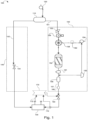
- Fig. 1
- is a process flow diagram showing a system for the catalytic upgrading of hydrocarbon fuels, according to one or more embodiments presently described.
- Fig. 2
- is a process flow diagram showing one embodiment of a system for the catalytic upgrading of hydrocarbon fuels with an integrated hydrocarbon vapor removal device.
- According to one or more embodiments as described in
FIG. 1 , avehicle 100 is provided comprising an on-board point-of-sale fuel tank 110, an operator accessible point-of-salefuel filling port 120, aninternal combustion engine 130 that is configured to provide motive force to thevehicle 100, anunreformed fuel subsystem 140, a reformedfuel subsystem 150, and fuel system control architecture comprising a reformateflow control device 160 and acetane rating controller 170. It should be understood that the on-board point-of-sale fuel tank 110 refers to a fuel tank that is integrated with, attached to, or is otherwise configured to move with, thevehicle 100, and which may be filled with a purchased fuel. - The operator accessible point-of-sale
fuel filling port 120 can be any conventional or yet to be developed fuel filling port that is structurally configured to transfer hydrocarbon fuel from a point-of-sale fuel dispenser to the on-board point-of-sale fuel tank 110. Theunreformed fuel subsystem 140 is structurally configured to transfer unreformed hydrocarbon fuel from the on-board point-of-sale fuel tank 110 to theinternal combustion engine 130 along an unreformedfuel supply pathway 142. The reformedfuel subsystem 150, which is described in further detail below, is structurally configured to reform hydrocarbon fuel from the on-board point-of-sale fuel tank 110 and transfer reformed fuel to theinternal combustion engine 130 along a reformedfuel supply pathway 151 separated from the unreformedfuel supply pathway 142. - The reformed
fuel subsystem 150 comprises acatalytic reactor 152, a divertedhydrocarbon fuel inlet 153 configured to direct a diverted portion of hydrocarbon fuel originating from the on-board point-of-sale fuel tank 110 to thecatalytic reactor 152, an oxidizinggas inlet 154 configured to direct an oxidizing gas to thecatalytic reactor 152, an unreacted oxidizinggas outlet 155 configured to direct at least a portion of an unreacted oxidizing gas from thecatalytic reactor 152, and a reformed hydrocarbon fuel outlet configured to direct reformed hydrocarbon fuel to theinternal combustion engine 130. - The
catalytic reactor 152 comprises a reforming catalyst and is structurally configured to alter a native cetane rating of the diverted hydrocarbon fuel in the presence of oxidizing gas from the oxidizinggas inlet 154 of the reformedfuel subsystem 150. Without being limited by theory, it is believed that oxidation of hydrocarbons may decrease hydrocarbon molecular weights and may result in increased cetane rating. Accordingly, it is believed that the presence of an oxidizing gas at the interface of a hydrocarbon fuel and a catalyst may result in increased cetane ratings for the hydrocarbon fuel. - The
cetane rating controller 170 and the reformateflow control device 160 cooperate to deliver an upgraded hydrocarbon fuel to a combustion zone of theinternal combustion engine 130 by controlling a volumetric ratio of unreformed hydrocarbon fuel from theunreformed fuel subsystem 140 to reformed hydrocarbon fuel from the reformedfuel subsystem 150. - It should be is noted that an on-board point-of-
sale fuel tank 110 and an "operator accessible point-of-salefuel filling port 120 are presented on a vehicle to facilitate vehicle fueling at a location where an operator executes at least a portion of the fuel dispensing process by transferring fuel to the on-board point-of-sale fuel tank 110 via the operator accessible point-of-salefuel filling port 120, and where the vehicle operator executes at least a portion of the payment transaction covering the cost of the dispensed fuel. It should be understood that the operator need not directly transfer fuel from the point-of-sale fuel dispenser into the operator accessible point-of-salefuel filling port 120. For example, in many circumstances, the operator may dispense fuel into an intermediate container such as a gas can or jerry can. - In the embodiment illustrated in
Fig. 1 , theinternal combustion engine 130 provides motive force to thevehicle 100. For example, theinternal combustion engine 130 may be coupled to wheels through a transmission or, in the case of avehicle 100 where the motive force is provided by a propeller, theinternal combustion engine 130 may be directly coupled to a propeller. Theinternal combustion engine 130 may also be configured to provide motive force indirectly such as in a hybrid system that utilizes power from a supply of electrical current supply to supplement the power generated by theinternal combustion engine 130. For example, theinternal combustion engine 130 may drive a generator and produce electricity; the electricity may then be used to power electric motors which propel the vehicle. The generator and the electric motor may have a variety of power management devices between them, including but not limited to, batteries, capacitors, frequency modulation devices, and variable resistors. - The
internal combustion engine 130 may comprise a diesel engine, a gasoline spark ignition engine, a gasoline compression ignition engine, a gasoline homogenous charge compression ignition engine, a premixed controlled auto-ignition engine, or a gasoline spark controlled compression ignition engine. Without being limited by theory, such engines may require differing cetane ratings at different operating parameters. Theinternal combustion engine 130 may comprise a gasoline homogenous charge compression ignition engine (HCCI). Generally, HCCI engines may have relatively greater fuel efficiencies than gasoline engines and relatively lesser NOx emissions. Generally, HCCI engines may have different cetane rating requirements from other types of gasoline engines. Theinternal combustion engine 130 may comprise as gasoline spark assisted ignition engine (SACI). According to some embodiments, the internal combustion engine may comprise a diesel engine. - It should be understood that, in some embodiments, no significant chemical modification is expected to occur in the
unreformed fuel subsystem 140. Theunreformed fuel subsystem 140 may comprise additional equipment such as, without limitation, valves, pumps, filters, and sensors. The unreformedfuel supply pathway 142 may comprise piping and associated equipment to transfer fuel from the on-board point-of-sale fuel tank 110 to theinternal combustion engine 130. As used in this disclosure, an unreformed hydrocarbon fuel refers to any hydrocarbon fuel which has the same octane rating as when it was purchased. - It should be understood that the reformed
fuel supply pathway 151 and the unreformedfuel supply pathway 142 need not be separated along their entire length. For example, both fuel supply pathways may share a single pipe as they exit the on-board point-of-sale fuel tank 110 and separate before the oxidizinggas inlet 154. - As depicted in
Fig. 1 , the reformedfuel subsystem 150 may comprise a reformedfuel storage tank 156 in a reformed fuel flow path between thecatalytic reactor 152 and the reformedhydrocarbon fuel outlet 180. According to some modes of operation, thecatalytic reactor 152 may reform fuel at a different rate than is required by theinternal combustion engine 130. For example, thecatalytic reactor 152 may reform fuel at a constant rate and theinternal combustion engine 130 may require reformed fuel only during periods of peak torque. In these modes of operation it may therefore be preferable to temporarily store reformed fuel in the reformedfuel storage tank 156. - Still referring to
FIG. 1 , the reformed fuel subsystem may further comprise a liquid-gas separator 157 in the reformed fuel flow path between thecatalytic reactor 152 and the unreacted oxidizinggas outlet 155. The liquid-gas separator 157 may be structurally configured to separate unreacted oxidizing gasses from hydrocarbon fuel and direct unreacted oxidizing gasses to the unreacted oxidizinggas outlet 155 of the reformedfuel subsystem 150. The unreacted oxidizing gas may be mixed, entrained, or dissolved in the liquid hydrocarbon fuel. It should be understood that gasses other than oxidizing gasses may be separated from hydrocarbon fuels in the liquid-gas separator, such as carbon dioxide, nitrogen, gaseous hydrocarbons, and carbon monoxide. - According to some embodiments, the
catalytic reactor 152 may be structurally configured to separate the unreacted oxidizing gasses from the hydrocarbon fuel and direct the unreacted oxidizing gasses to the unreacted oxidizinggas outlet 155 of the reformedfuel subsystem 150. In such embodiments, the liquid-gas separator 157 may be a region or component of thecatalytic reactor 152. Additionally, in such embodiments, the unreacted oxidizinggas outlet 155 may connect directly to thecatalytic reactor 152. - The
catalytic reactor 152 may alter the native cetane rating of the diverted hydrocarbon fuel by contacting the diverted hydrocarbon fuel with an oxidizing gas and the reforming catalyst. As used in this disclosure, the native cetane rating of a hydrocarbon fuel is the cetane rating of the hydrocarbon fuel as it first enters the on-board point-of-sale fuel tank 110. - Referring further to
FIG. 1 , according to some embodiments, the reformedfuel subsystem 150 may further comprise a mixingregion 158 disposed between the oxidizinggas inlet 154 and the reforming catalyst of thecatalytic reactor 152. The reformed fuel subsystem may be configured to introduce the oxidizing gas to the hydrocarbon fuel in themixing region 158. Themixing region 158 may further comprise one or more of a sparger, a packed column, an impeller, a bubble column, a plate tower, a stirred vessel, a jet-mixed vessel, a static mixer, a jet ejector, a thin film mixer, a slurry reactor, a baffled agitator, or combinations thereof. Themixing region 158 may comprise a dedicated device, as depicted inFIG. 1 . The mixing region may comprise a portion of another device. For example, the mixing region may be defined in a portion of thecatalytic reactor 152. - The reforming catalyst of the
catalytic reactor 152 may comprise one or more metals, metal oxides, organometalics, polyoxometalates, organotransition-metals ions, N-heteroaromatic compounds, N-hydroxy catalytic systems, N-hydroxyphthalimide (NHPI), or any combination thereof. According to some embodiments, the reforming catalyst may comprise a N-hydroxy catalyst. For example, the reforming catalyst may comprise N-hydroxyphthalimide (NHPI). Without being limited by theory, it is believed that N-hydroxy catalyst systems, such as NHPI, may be able to catalyze the selective oxidation of hydrocarbons by molecular oxygen under moderate conditions. - As depicted in
Fig. 1 the reformedfuel subsystem 150 may further comprise acatalyst removal device 181. The reforming catalyst may be a homogenous catalyst and thecatalyst removal device 181 may be structurally configured to separate the homogenous catalyst from a liquid hydrocarbon fuel. Thecatalyst removal device 181 may be located along the reformedfuel supply pathway 151 between thecatalytic reactor 152 and the liquid-gas separator 157. Thecatalyst removal device 181 may be located at any point along the reformedfuel supply pathway 151 between thecatalytic reactor 152 and the reformedhydrocarbon fuel outlet 180. The catalyst removal device may be defined as a subcomponent of thecatalytic reactor 152 or a subcomponent of the liquid-gas separator 157. It should be understood that a homogenous catalyst is a catalyst which is capable of forming a mixture with one or more of reactants, products, or solvents. The homogenous catalyst may form a solution requiring chemical separation or it may be a suspension capable of separation through mechanical means. The catalyst removal device may operate on distillation, adsorption, filtration, settling, or magnetism. - The oxidizing
gas inlet 154 may be structurally configured to introduce air into the reformedfuel subsystem 150. The oxidizinggas inlet 154 may be structurally configured to introduce air into the reformedfuel subsystem 150 via the mixingregion 158 or upstream of the mixingregion 158. - The oxidizing
gas inlet 154 may further comprise anoxygen enrichment device 182. According to some embodiments, the oxidizinggas inlet 154 and theoxygen enrichment device 182 may be structurally configured to cooperate to introduce an oxygen enriched gas into the reformedfuel subsystem 150. The oxygen enrichment device may operate on principles of pressure swing adsorption, membrane enrichment, or electrolysis. Without being limited by theory, it is believed that increasing concentrations of oxygen may promote increased reaction rates and decrease excess gas. Excess gas may need to be removed in the liquid-gas separator 157; therefore, avoiding excess gas may decrease system size and cost. - The unreacted oxidizing
gas outlet 155 may be structurally configured to direct the unreacted oxidizing gasses to an uncontained atmosphere surrounding the vehicle. As used in this disclosure the term "to" refers to either direct or indirect connections. For example, the unreacted oxidizinggas outlet 155 may direct the unreacted oxidizing gasses through one or more other components before discharging the unreacted oxidizing gasses into an uncontained atmosphere surrounding the vehicle. For example, the unreacted oxidizinggas outlet 155 may direct the unreacted oxidizing gasses through the oxidizinggas inlet 154. Without limitation, the other components may be theinternal combustion engine 130, a pollution control device, or a hydrocarbon vapor removal device. - As depicted in
Fig. 2 , the unreacted oxidizinggas outlet 155 may further comprise a hydrocarbonvapor removal device 302 and avapor recycle line 304 connecting the hydrocarbonvapor removal device 302 to an intake of theinternal combustion engine 130. The hydrocarbonvapor removal device 302 may be structurally configured to separate hydrocarbon vapors from oxidizing gasses and discharge the hydrocarbon vapors into the vapor recycleline 304. It should be understood that the vapor recycleline 304 need not directly connect the hydrocarbonvapor removal device 302 and the intake of theinternal combustion engine 130. For example, according to some embodiments, the vapor recycleline 304 may directly connect the hydrocarbonvapor removal device 302 with the on-board point-of-sale fuel tank 110, or with the oxidizinggas inlet 154, or with the reformedfuel storage tank 156, or with the intake of theinternal combustion engine 130, or with any point along the respective flow paths defined by the reformed orunreformed fuel subsystems - The hydrocarbon
vapor removal device 302 may be structurally configured to chill unreacted oxidizing gas in the unreacted oxidizinggas outlet 155. Without being limited by theory, it is believed that most hydrocarbon vapors may be condensed at relatively lesser temperatures. As such, it may be advantageous to chill the unreacted oxidizing to condense hydrocarbon vapors which may be mixed with the unreacted oxidizing gas. According to some embodiments, the hydrocarbonvapor removal device 302 may be structurally configured to remove hydrocarbon vapor from unreacted gas in the unreacted oxidizinggas outlet 155 through absorption, adsorption, or membrane technology. - The fuel system control architecture may be in communication with an unreformed fuel
flow control device 144 and a reformedfuel supply pump 159. The reformateflow control device 160 may be disposed within the reformed fuel subsystem. The reformateflow control device 160 may comprise one or both of pumps or valves. - The
cetane rating controller 170 may be a stand-alone controller or a controller integrated with a controller that is programmed to execute additional functionality. For example, the stand-alone controller may be a device dedicated to the control of cetane rating. For example, the controller programmed to execute additional functionality may be an engine control unit. - According to some embodiments, the
cetane rating controller 170 may be programmed to determine the desired cetane rating at least in part from a lookup table and deliver the upgraded hydrocarbon fuel by controlling the volumetric ratio of unreformed hydrocarbon fuel to reformed hydrocarbon fuel as a function of the desired cetane rating. As used in this disclosure, the desired cetane rating refers to an optimal cetane rating calculated based on engine operating parameters. Relevant engine operating parameters may include without limitation, throttle position, coolant temperature, intake air pressure, intake air temperature, instantaneous torque, revolutions per minute, or timing advance. - According to some embodiments, the
cetane rating controller 170 may be programmed to determine the delivered cetane rating at least in part from a lookup table. As used in this disclosure, the delivered cetane rating is the average cetane rating of the fuel inside the combustion zone of aninternal combustion engine 130. Generally, it may be possible to calculate the delivered cetane rating of the reformed fuel based on properties such as unreformed fuel cetane rating, catalyst activity, catalytic reactor temperature, flux at the oxidizing gas inlet, and catalyst age. Generally, empirical data on these parameters may be combined to calculate an expected value for the delivered cetane rating. - The fuel system control architecture may further comprise a cetane rating
sensor feedback loop 172 in communication with thecetane rating controller 170. According to some embodiments, the cetane rating controller may be programmed to utilize the cetane ratingsensor feedback loop 172 to at least partially control the volumetric ratio of unreformed hydrocarbon fuel to reformed hydrocarbon fuel. In the present configuration, the cetane ratingsensor feedback loop 172 and thecetane rating controller 170 may cooperate to ensure reliable control of the delivered cetane rating. It should be understood that, the cetane rating sensor feedback loop may comprise one or more dedicated sensors, one or more multipurpose sensors, one or more calculated values, or any combination thereof. For example, according to some embodiments, the cetane rating sensor feedback loop may comprise one or more of combustion pressure sensors or measurements, engine timing sensors or measurements, engine dynamic torque sensors or measurements, density sensors or measurements, or distillation properties. Generally, the cetane rating of a hydrocarbon fuel may be calculated based on density and distillation properties. Alternatively, the cetane rating of a hydrocarbon fuel may be determined through the measurement of engine properties as the hydrocarbon fuel is used in the engine. - The reformate
flow control device 160 may comprise a single flow control valve positioned in the reformed fuel subsystem. The reformateflow control device 160 may comprise a plurality of flow control valves positioned in the reformed fuel subsystem, the unreformed fuel subsystem, or both. It should be understood that the reformate flow control device may be located at any point along the reformed fuel supply pathway, not just at reformateflow control device 160 as indicated inFIG. 1 . - The reformate
flow control device 160 may comprise one or more pumps positioned in the reformedfuel subsystem 150, theunreformed fuel subsystem 140 or both. Generally, flow control in a closed system may be achieved without valves. As such, it is possible to use one or more pumps to achieve optimal flow control. It should be understood that the reformateflow control device 160 may be located at any point along the reformedfuel supply pathway 151, not just at reformedfuel supply pump 159 as indicated inFIG. 1 . - As used in this disclosure, the delivered fuel refers to the fuel which reaches the combustion zone of the internal combustion engine. As used in this disclosure, an upgraded hydrocarbon fuel is one which has a higher cetane rating relative to the native cetane rating of the hydrocarbon fuel.
- The volumetric ratio may be controlled by controlling one or both of the flow in the reformed
fuel subsystem 150 and the flow in theunreformed fuel subsystem 140. The fuel system control architecture may be structurally configured to control the volumetric ratio by controlling volumetric delivery of both unreformed and reformed hydrocarbon fuel to theinternal combustion engine 130. The fuel system control architecture may be structurally configured to control the volumetric ratio by controlling volumetric delivery of reformed hydrocarbon fuel to theinternal combustion engine 130. - The reformed fuel and the unreformed fuel may be mixed anywhere between the outlet of the
catalytic reactor 152 and the combustion zone of theinternal combustion engine 130. The fuel system control architecture may be structurally configured to control the volumetric ratio at a fuel delivery port of theinternal combustion engine 130 or at a fuel mixing point upstream of the fuel delivery port of theinternal combustion engine 130. The fuel system control architecture may be structurally configured to control the volumetric ratio by controlling fuel delivery to separate reformed and unreformed fuel delivery ports of theinternal combustion engine 130. As used presently, volumetric ratio refers to the ratio of reformed hydrocarbon fuel to unreformed hydrocarbon fuel. - According to some embodiments, the
vehicle 100 may comprise an exhaust gas recycle system. The exhaust gas recycle system may be structurally configured to capture at least a portion of an exhaust gas originating from theinternal combustion engine 130 and direct at least a portion of the captured exhaust gas to a combustion zone of theinternal combustion engine 130. Without being limited by theory, an exhaust gas recycle system may be used to decrease the NOx emissions of an internal combustion engine by decreasing the O2 concentration of the incoming air. - According to some embodiments, the unreacted oxidizing
gas outlet 155 may be structurally configured to direct at least a portion of the unreacted oxidizing gasses to a combustion zone of theinternal combustion engine 130. Without being limited by theory, it is believed that the unreacted oxidizing gas outlet may contain gas with a lower oxygen concentration than ambient air. It is therefore believed that introducing the at least a portion of the unreacted oxidizing gasses into a combustion zone of theinternal combustion engine 130 may decrease oxygen concentrations in the combustion zone of the internal combustion engine and accordingly decrease the NOx emissions from the internal combustion engine exhaust. - As used in this disclosure, cetane rating is an indicator of the combustion speed and compression needed for ignition of a hydrocarbon fuel. While cetane rating is commonly applied to diesel fuels, a cetane rating may be determined for any fuel. For example, a cetane rating may be determined for diesel, gasoline, kerosene, or naphtha.
- According to some embodiments, a method for on-board catalytic upgrading of hydrocarbon fuels may comprise passing a hydrocarbon fuel along a reformed
fuel subsystem 150 from an on-board point-of-sale fuel tank 110 into acatalytic reactor 152 and passing an oxidizing gas through an oxidizinggas inlet 154 into thecatalytic reactor 152. The oxidizing gas, a reforming catalyst, and the hydrocarbon fuel may then be contacted to alter the native cetane rating of the hydrocarbon fuel and thereby produce a reformed hydrocarbon fuel. A volumetric ratio of an unreformed hydrocarbon fuel from the on-board point-of-sale fuel tank 110 may then be contacted with the reformed hydrocarbon fuel to produce an upgraded hydrocarbon fuel. The upgraded hydrocarbon fuel may be introduced into a combustion zone of aninternal combustion engine 130.
Claims (14)
- A vehicle comprisingan on-board point-of-sale fuel tank (110),an operator accessible point-of-sale fuel filling port (120) that is structurally configured to transfer hydrocarbon fuel from a point-of-sale fuel dispenser to the on-board point-of-sale fuel tank (110),an internal combustion engine (130) that is configured to provide motive force to the vehicle (100), an unreformed fuel subsystem (140) that is structurally configured to transfer unreformed hydrocarbon fuel from the on-board point-of-sale fuel tank (110) to the internal combustion engine (130) along an unreformed fuel supply pathway (142),a reformed fuel subsystem (150) that is structurally configured to reform hydrocarbon fuel from the on-board point-of-sale fuel tank (110) and transfer reformed fuel to the internal combustion engine (130) along a reformed fuel supply pathway (151) separated from the unreformed fuel supply pathway (142), andfuel system control architecture comprising a reformate flow control device (160), wherein:the reformed fuel subsystem (150) comprises a catalytic reactor (152), a diverted hydrocarbon fuel inlet (153) configured to direct a diverted portion of hydrocarbon fuel originating from the on-board point-of-sale fuel tank (110) to the catalytic reactor (152), an oxidizing gas inlet (154) configured to direct an oxidizing gas to the catalytic reactor (152), an unreacted oxidizing gas outlet (155) configured to direct at least a portion of an unreacted oxidizing gas from the catalytic reactor (152), and a reformed hydrocarbon fuel outlet (180) configured to direct reformed hydrocarbon fuel to the internal combustion engine (130);characterized in that:
the fuel system control architecture further comprises a cetane rating controller (170), wherein:the catalytic reactor (152) comprises a reforming catalyst and is structurally configured to alter a native cetane rating of the diverted hydrocarbon fuel in the presence of oxidizing gas from the oxidizing gas inlet (154) of the reformed fuel subsystem (150);the unreacted oxidizing gas outlet (155) further comprises a hydrocarbon vapor removal device (302) and a vapor recycle line (304) connecting the hydrocarbon vapor removal device (302) to an intake of the internal combustion engine (130) where the hydrocarbon vapor removal device (302) is structurally configured to separate hydrocarbon vapors from unreacted oxidizing gases and discharge the hydrocarbon vapors into the vapor recycle line (304); andthe cetane rating controller (170) and the reformate flow control device (160) cooperate to deliver an upgraded hydrocarbon fuel to a combustion zone of the internal combustion engine (130) by controlling a volumetric ratio of unreformed hydrocarbon fuel from the unreformed fuel subsystem (140) to reformed hydrocarbon fuel from the reformed fuel subsystem (150). - The vehicle of claim 1, wherein the reformed fuel subsystem (150) comprises a reformed fuel storage tank (156) in a reformed fuel flow path between the catalytic reactor (152) and the reformed hydrocarbon fuel outlet (180).
- The vehicle of claim 1, wherein:the reformed fuel subsystem (150) further comprises a liquid-gas separator (157) in the reformed fuel flow path between the catalytic reactor (152) and the reformed hydrocarbon fuel outlet (180); andthe liquid-gas separator (157) is structurally configured to separate unreacted oxidizing gasses from hydrocarbon fuel and direct unreacted oxidizing gasses to the unreacted oxidizing gas outlet (155) of the reformed fuel subsystem (150).
- The vehicle of claim 1, wherein the cetane rating controller (170) is a stand-alone controller or a controller integrated with a controller that is programmed to execute additional functionality.
- The vehicle of claim 1, wherein:the fuel system control architecture further comprises a cetane rating sensor feedback loop (172) in communication with the cetane rating controller; andthe cetane rating controller (170) is programmed to utilize the cetane rating sensor feedback loop (172) to at least partially control the volumetric ratio of unreformed hydrocarbon fuel to reformed hydrocarbon fuel.
- The vehicle of claim 1, wherein:the reformed fuel subsystem (150) further comprises a mixing region (158) disposed between the oxidizing gas inlet (154) and the reforming catalyst; andthe reformed fuel subsystem (150) is configured to introduce the oxidizing gas to the hydrocarbon fuel in the mixing region (158).
- The vehicle of claim 1, wherein:the oxidizing gas inlet (154) further comprises an oxygen enrichment device (182); andthe oxidizing gas inlet (154) and the oxygen enrichment device (182) are structurally configured to cooperate to introduce an oxygen enriched gas into the reformed fuel subsystem (150).
- The vehicle of claim 1, wherein the vehicle comprises an exhaust gas recycle system that is structurally configured to capture at least a portion of an exhaust gas originating from the internal combustion engine (130) and direct at least a portion of the captured exhaust gas to a combustion zone of the internal combustion engine.
- The vehicle of claim 1, further comprising a catalyst removal device (181), wherein:the reforming catalyst is a homogenous catalyst; andthe catalyst removal device (181) is structurally configured to separate the homogenous catalyst from a liquid hydrocarbon fuel.
- The vehicle of claim 1, wherein:the reformed fuel subsystem (150) further comprises a liquid-gas separator (157) in the reformed fuel flow path between the catalytic reactor (152) and the reformed hydrocarbon fuel outlet (180);the liquid-gas separator (157) is structurally configured to separate unreacted oxidizing gasses from hydrocarbon fuel and direct unreacted oxidizing gasses to the unreacted oxidizing gas outlet (155) of the reformed fuel subsystem (150);the fuel system control architecture further comprises a cetane rating sensor feedback loop (172) in communication with the cetane rating controller;the cetane rating controller (170) is programmed to utilize the cetane rating sensor feedback loop (172) to at least partially control the volumetric ratio of unreformed hydrocarbon fuel to reformed hydrocarbon fuel;the reformed fuel subsystem (150) further comprises a mixing region (158) disposed between the oxidizing gas inlet (154) and the reforming catalyst;the reformed fuel subsystem (150) is configured to introduce the oxidizing gas to the hydrocarbon fuel in the mixing region (158);the unreacted oxidizing gas outlet (155) further comprises a hydrocarbon vapor removal device (302) and a vapor recycle line (304) connecting the hydrocarbon vapor removal device t(302) o an intake of the internal combustion engine;the hydrocarbon vapor removal device (302) is structurally configured to separate hydrocarbon vapors from unreacted oxidizing gasses and discharge the hydrocarbon vapors into the vapor recycle line (304);the oxidizing gas inlet (154) further comprises an oxygen enrichment device (182); andthe oxidizing gas inlet (154) and the oxygen enrichment device (182) are structurally configured to cooperate to introduce an oxygen enriched gas into the reformed fuel subsystem (150).
- The vehicle of any of the preceding claims, wherein the reforming catalyst comprises a N-hydroxy catalyst.
- The vehicle of any of claims 1 through 10, wherein the reforming catalyst comprises one or more metals, metal oxides, organometalics, polyoxometalates, organotransition-metals ions, N-heteroaromatic compounds, N-hydroxy catalytic systems, or any combination thereof.
- A system comprising:a point-of-sale fuel tank (110),an operator accessible point-of-sale fuel filling port (120) that is structurally configured to transfer hydrocarbon fuel from a point-of-sale fuel dispenser to the point-of-sale fuel tank (110),an internal combustion engine,an unreformed fuel subsystem (140) that is structurally configured to transfer unreformed hydrocarbon fuel from the point-of-sale fuel tank (110) to the internal combustion engine (130) along an unreformed fuel supply pathway (142),a reformed fuel subsystem (150) that is structurally configured to reform hydrocarbon fuel from the point-of-sale fuel tank (110) and transfer reformed fuel to the internal combustion engine (130) along a reformed fuel supply pathway (151) separated from the unreformed fuel supply pathway (142), andfuel system control architecture comprising a reformate flow control device (160), wherein:
the reformed fuel subsystem (150) comprises a catalytic reactor (152), a diverted hydrocarbon fuel inlet (153) configured to direct a diverted portion of hydrocarbon fuel originating from the point-of-sale fuel tank (110) to the catalytic reactor (152), an oxidizing gas inlet (154) configured to direct an oxidizing gas to the catalytic reactor (152), an unreacted oxidizing gas outlet (155) configured to direct at least a portion of an unreacted oxidizing gas from the catalytic reactor (152), and a reformed hydrocarbon fuel outlet configured to direct reformed hydrocarbon fuel to the internal combustion engine;characterized in that:
the fuel system control architecture further comprises a cetane rating controller, wherein:the catalytic reactor (152) comprises a reforming catalyst and is structurally configured to alter a native cetane rating of the diverted hydrocarbon fuel in the presence of oxidizing gas from the oxidizing gas inlet (154) of the reformed fuel subsystem (150);the unreacted oxidizing gas outlet (155) further comprises a hydrocarbon vapor removal device (302) and a vapor recycle line (304) connecting the hydrocarbon vapor removal device (302) to an intake of the internal combustion engine (130) where the hydrocarbon vapor removal device (302) is structurally configured to separate hydrocarbon vapors from unreacted oxidizing gases and discharge the hydrocarbon vapors into the vapor recycle line (304); andthe cetane rating controller (170) and the reformate flow control device (160) cooperate to deliver an upgraded hydrocarbon fuel to a combustion zone of the internal combustion engine (130) by controlling a volumetric ratio of unreformed hydrocarbon fuel from the unreformed fuel subsystem (140) to reformed hydrocarbon fuel from the reformed fuel subsystem (150). - A method for on-board catalytic upgrading of hydrocarbon fuels in a vehicle (100) according to claim 1 or in a system according to claim 13, the method comprising:passing a hydrocarbon fuel along a reformed fuel subsystem (150) from an on-board point-of-sale fuel tank (110) into a catalytic reactor (152);passing an oxidizing gas through an oxidizing gas inlet (154) into the catalytic reactor (152);contacting the oxidizing gas, a reforming catalyst, and the hydrocarbon fuel to alter the native cetane rating of the hydrocarbon fuel and thereby produce a reformed hydrocarbon fuel;passing an unreacted oxidizing gas from the catalytic reactor (152) into a hydrocarbon vapor removal device (302) and separating hydrocarbon vapors from the unreacted oxidizing gas;discharging the hydrocarbon vapors separated from the unreacted oxidizing gas into a vapor recycle line (304) connecting the hydrocarbon vapor removal device (302) to an intake of the internal combustion engine;contacting an unreformed hydrocarbon fuel from the on-board point-of-sale fuel tank (110) with the reformed hydrocarbon fuel at a controlled volumetric ratio to produce an upgraded hydrocarbon fuel; andintroducing the upgraded hydrocarbon fuel into a combustion zone of an internal combustion engine (130).
Applications Claiming Priority (2)
| Application Number | Priority Date | Filing Date | Title |
|---|---|---|---|
| US16/243,180 US11028805B2 (en) | 2019-01-09 | 2019-01-09 | System and method for on-board catalytic upgrading of hydrocarbon fuels |
| PCT/US2020/012651 WO2020146443A1 (en) | 2019-01-09 | 2020-01-08 | System and method for on-board catalytic upgrading of hydrocarbon fuels |
Publications (2)
| Publication Number | Publication Date |
|---|---|
| EP3887665A1 EP3887665A1 (en) | 2021-10-06 |
| EP3887665B1 true EP3887665B1 (en) | 2025-03-19 |
Family
ID=69411577
Family Applications (1)
| Application Number | Title | Priority Date | Filing Date |
|---|---|---|---|
| EP20703125.3A Active EP3887665B1 (en) | 2019-01-09 | 2020-01-08 | System and method for on-board catalytic upgrading of hydrocarbon fuels |
Country Status (6)
| Country | Link |
|---|---|
| US (1) | US11028805B2 (en) |
| EP (1) | EP3887665B1 (en) |
| KR (1) | KR102845014B1 (en) |
| CN (1) | CN113260780B (en) |
| SA (1) | SA521422487B1 (en) |
| WO (1) | WO2020146443A1 (en) |
Families Citing this family (4)
| Publication number | Priority date | Publication date | Assignee | Title |
|---|---|---|---|---|
| EP4469398A4 (en) * | 2022-01-28 | 2026-01-28 | M2X Energy Inc | METHOD, SYSTEMS AND DEVICE FOR CARBON COLLECTION, USE AND STORAGE |
| US12012558B1 (en) * | 2022-12-14 | 2024-06-18 | Saudi Arabian Oil Company | Microchannel reactors for catalytic oxidation of hydrocarbon fuels |
| US12006479B1 (en) * | 2022-12-15 | 2024-06-11 | Saudi Arabian Oil Company | Systems and processes for reforming a liquid hydrocarbon fuel |
| US12358464B2 (en) * | 2023-10-09 | 2025-07-15 | Bruno Thierry Robert Pellichero | System and method of immobilizing a vehicle to prevent vehicle theft |
Citations (1)
| Publication number | Priority date | Publication date | Assignee | Title |
|---|---|---|---|---|
| US7603225B2 (en) * | 2007-08-03 | 2009-10-13 | Nissan Motor Co., Ltd. | Combustion control of internal combustion engine |
Family Cites Families (40)
| Publication number | Priority date | Publication date | Assignee | Title |
|---|---|---|---|---|
| US4494961A (en) | 1983-06-14 | 1985-01-22 | Mobil Oil Corporation | Increasing the cetane number of diesel fuel by partial oxidation _ |
| EP0252606A3 (en) | 1986-06-09 | 1989-03-15 | Exxon Research And Engineering Company | Process for increasing the cetane number of diesel fuels |
| US5064733A (en) | 1989-09-27 | 1991-11-12 | Gas Research Institute | Electrochemical conversion of CO2 and CH4 to C2 hydrocarbons in a single cell |
| US5316558A (en) | 1990-11-02 | 1994-05-31 | Frank Gonzalez | Catalytic clean-combustion-promoter compositions for liquid hydrocarbon fuels used in internal combustion engines |
| US5425332A (en) * | 1993-08-20 | 1995-06-20 | Massachusetts Institute Of Technology | Plasmatron-internal combustion engine system |
| US5881559A (en) | 1995-07-28 | 1999-03-16 | Isuzu Ceramics Research Institute Co., Ltd. | Hybrid electric vehicle |
| US6230683B1 (en) * | 1997-08-22 | 2001-05-15 | Cummins Engine Company, Inc. | Premixed charge compression ignition engine with optimal combustion control |
| JP2000213444A (en) | 1999-01-26 | 2000-08-02 | Komatsu Ltd | Engine ignition timing control apparatus and method |
| DE60025412T2 (en) | 1999-06-01 | 2006-08-31 | Nissan Motor Co., Ltd., Yokohama | Fuel supply device of an internal combustion engine |
| US6550430B2 (en) * | 2001-02-27 | 2003-04-22 | Clint D. J. Gray | Method of operating a dual fuel internal |
| US6378489B1 (en) | 2001-05-24 | 2002-04-30 | Rudolf H. Stanglmaier | Method for controlling compression ignition combustion |
| US6827047B2 (en) | 2001-12-19 | 2004-12-07 | Honda Giken Kogyo Kabushiki Kaisha | Vehicle provided with internal combustion engine and fuel reforming/supplying functions |
| US6743524B2 (en) | 2002-05-23 | 2004-06-01 | General Electric Company | Barrier layer for an article and method of making said barrier layer by expanding thermal plasma |
| US6662760B1 (en) * | 2002-10-17 | 2003-12-16 | Southwest Research Institute | Method and apparatus for controlling combustion timing in an homogenous-charge compression-ignition engine |
| US6981472B2 (en) * | 2002-11-18 | 2006-01-03 | Massachusetts Institute Of Technology | Homogeneous charge compression ignition control utilizing plasmatron fuel converter technology |
| KR200312394Y1 (en) * | 2003-01-10 | 2003-05-13 | 조정현 | Exhaust gas/fuel reduction apparatus for an internal combustion |
| US7017530B2 (en) | 2003-06-27 | 2006-03-28 | Honda Motor Co., Ltd. | Method for controlling compression ignition internal combustion engine |
| CN1856562B (en) | 2003-09-03 | 2010-06-23 | 国际壳牌研究有限公司 | Fuel composition, method for producing same and use thereof |
| EP1706628B1 (en) * | 2003-12-01 | 2012-04-25 | Shell Internationale Research Maatschappij B.V. | Process for operating a compression ignition internal combustion engine in combination with a catalytic reformer |
| JP4173852B2 (en) | 2004-11-04 | 2008-10-29 | 本田技研工業株式会社 | Control method for compression ignition internal combustion engine |
| JP2006226172A (en) | 2005-02-17 | 2006-08-31 | Honda Motor Co Ltd | Control method for compression ignition internal combustion engine |
| JP2006233864A (en) | 2005-02-24 | 2006-09-07 | Honda Motor Co Ltd | Control method for compression ignition internal combustion engine |
| US9233203B2 (en) | 2005-05-06 | 2016-01-12 | Medtronic Minimed, Inc. | Medical needles for damping motion |
| US7484358B2 (en) * | 2005-06-17 | 2009-02-03 | Gm Global Technology Operations, Inc. | Continuous reforming of diesel fuel for NOx reduction |
| ES2534469T3 (en) | 2006-05-17 | 2015-04-23 | Dow Global Technologies Llc | Polymerization process of polyethylene in high temperature solution |
| KR20100031500A (en) | 2007-05-04 | 2010-03-22 | 프린시플 에너지 솔루션스, 인코포레이티드 | Production of hydrocarbons from carbon and hydrogen sources |
| JP2010101194A (en) | 2008-10-21 | 2010-05-06 | Japan Energy Corp | Gasoline engine |
| JP2010144690A (en) | 2008-12-22 | 2010-07-01 | Nissan Motor Co Ltd | Fuel supply device |
| TWI370574B (en) | 2009-03-31 | 2012-08-11 | Open Minder Group Ltd | System and method for managing composite battery energy |
| US20110247573A1 (en) | 2010-04-07 | 2011-10-13 | Mccann David M | Oxygenate dehydration system for compression ignition engines |
| EP2797962B1 (en) | 2011-12-29 | 2015-11-18 | Dow Global Technologies LLC | Process for producing low molecular weight ethylene- and alpha-olefin-based materials |
| KR101546937B1 (en) | 2012-04-04 | 2015-08-25 | 삼성전자 주식회사 | Film for Backlight Unit and Backlight Unit and Liquid Crystal Display Including Same |
| JP6007691B2 (en) | 2012-09-12 | 2016-10-12 | 富士ゼロックス株式会社 | Electrophotographic photosensitive member, process cartridge, and image forming apparatus |
| AT512922B1 (en) * | 2012-10-24 | 2013-12-15 | Ge Jenbacher Gmbh & Co Og | internal combustion engine |
| US8959901B2 (en) | 2013-04-29 | 2015-02-24 | Toyota Motor Engineering & Manufacturing North America, Inc. | Metal-gas battery system |
| JP5979643B2 (en) * | 2013-11-20 | 2016-08-24 | 本田技研工業株式会社 | Control device for internal combustion engine |
| US9797349B2 (en) * | 2015-05-21 | 2017-10-24 | Southwest Research Institute | Combined steam reformation reactions and water gas shift reactions for on-board hydrogen production in an internal combustion engine |
| JP2018003801A (en) * | 2016-07-07 | 2018-01-11 | 本田技研工業株式会社 | Fuel reformation system |
| JP2018003799A (en) | 2016-07-07 | 2018-01-11 | 本田技研工業株式会社 | Fuel reformation system |
| US11655548B2 (en) | 2017-06-21 | 2023-05-23 | Cornell University | System for chemical conversion and electrical energy generation |
-
2019
- 2019-01-09 US US16/243,180 patent/US11028805B2/en active Active
-
2020
- 2020-01-08 WO PCT/US2020/012651 patent/WO2020146443A1/en not_active Ceased
- 2020-01-08 CN CN202080007926.7A patent/CN113260780B/en active Active
- 2020-01-08 KR KR1020217020955A patent/KR102845014B1/en active Active
- 2020-01-08 EP EP20703125.3A patent/EP3887665B1/en active Active
-
2021
- 2021-07-07 SA SA521422487A patent/SA521422487B1/en unknown
Patent Citations (1)
| Publication number | Priority date | Publication date | Assignee | Title |
|---|---|---|---|---|
| US7603225B2 (en) * | 2007-08-03 | 2009-10-13 | Nissan Motor Co., Ltd. | Combustion control of internal combustion engine |
Also Published As
| Publication number | Publication date |
|---|---|
| SA521422487B1 (en) | 2023-02-19 |
| WO2020146443A1 (en) | 2020-07-16 |
| KR20210111769A (en) | 2021-09-13 |
| KR102845014B1 (en) | 2025-08-13 |
| US11028805B2 (en) | 2021-06-08 |
| US20200217280A1 (en) | 2020-07-09 |
| EP3887665A1 (en) | 2021-10-06 |
| CN113260780A (en) | 2021-08-13 |
| CN113260780B (en) | 2023-05-26 |
Similar Documents
| Publication | Publication Date | Title |
|---|---|---|
| EP3887665B1 (en) | System and method for on-board catalytic upgrading of hydrocarbon fuels | |
| US7597068B2 (en) | Internal combustion engine with fuel reforming apparatus | |
| KR100783345B1 (en) | Internal combustion engine utilizing hydrogen | |
| US7344789B2 (en) | Hypergolic hydrogen generation system for fuel cell power plants | |
| US6159626A (en) | Fuel cell system logic for differentiating between rapid and normal shutdown commands | |
| US20020124836A1 (en) | Pox cold start vapor system | |
| US20140356738A1 (en) | Ammonia based system to prepare and utilize hydrogen to produce electricity | |
| WO1994024432A1 (en) | Fuel modification method and apparatus for reduction of pollutants emitted from internal combustion engines | |
| US12134990B2 (en) | System for remotely monitoring and controlling operation of a hydro-diesel engine | |
| CN113446137A (en) | Hydrogen-ammonia dual-fuel engine system for catalytically reforming methanol to supply hydrogen by waste gas waste heat | |
| CN109250685B (en) | Vehicle-mounted methanol reforming system and control method for producing hydrogen-rich gas from tail gas | |
| CN100427741C (en) | Hydrogen utilizing internal combustion engine | |
| US20030162062A1 (en) | Fuel cell apparatus with means for supplying two different hydrocarbon mixtures to a fuel converter for making hydrogen-enriched fluid | |
| US20050242588A1 (en) | Integrated fuel cell and additive gas supply system for a power generation system including a combustion engine | |
| US20160333283A1 (en) | Fuel reforming system | |
| US6653006B2 (en) | System for fuel cell reformer start-up | |
| US20030145730A1 (en) | Method for separating fuel out of an off-gas and associated device | |
| JP2016211492A (en) | Fuel reformer and mixer used in the device | |
| JP2001115898A (en) | Dimethyl ether storage device | |
| CN1833333A (en) | Hypergolic hydrogen generation system for fuel cell power plants | |
| JPS5835257A (en) | Fuel supply system for engine | |
| JP2018003803A (en) | Fuel reforming system | |
| CN121139217A (en) | Sliding arc plasma fuel reforming-assisted engine systems and applications | |
| JP2008088383A (en) | Feeder for heavy fuel oil | |
| EP4093960A1 (en) | Fuel treatment system and process |
Legal Events
| Date | Code | Title | Description |
|---|---|---|---|
| STAA | Information on the status of an ep patent application or granted ep patent |
Free format text: STATUS: UNKNOWN |
|
| STAA | Information on the status of an ep patent application or granted ep patent |
Free format text: STATUS: THE INTERNATIONAL PUBLICATION HAS BEEN MADE |
|
| PUAI | Public reference made under article 153(3) epc to a published international application that has entered the european phase |
Free format text: ORIGINAL CODE: 0009012 |
|
| STAA | Information on the status of an ep patent application or granted ep patent |
Free format text: STATUS: REQUEST FOR EXAMINATION WAS MADE |
|
| 17P | Request for examination filed |
Effective date: 20210629 |
|
| AK | Designated contracting states |
Kind code of ref document: A1 Designated state(s): AL AT BE BG CH CY CZ DE DK EE ES FI FR GB GR HR HU IE IS IT LI LT LU LV MC MK MT NL NO PL PT RO RS SE SI SK SM TR |
|
| DAV | Request for validation of the european patent (deleted) | ||
| DAX | Request for extension of the european patent (deleted) | ||
| STAA | Information on the status of an ep patent application or granted ep patent |
Free format text: STATUS: EXAMINATION IS IN PROGRESS |
|
| 17Q | First examination report despatched |
Effective date: 20230713 |
|
| GRAP | Despatch of communication of intention to grant a patent |
Free format text: ORIGINAL CODE: EPIDOSNIGR1 |
|
| STAA | Information on the status of an ep patent application or granted ep patent |
Free format text: STATUS: GRANT OF PATENT IS INTENDED |
|
| INTG | Intention to grant announced |
Effective date: 20241118 |
|
| GRAS | Grant fee paid |
Free format text: ORIGINAL CODE: EPIDOSNIGR3 |
|
| GRAA | (expected) grant |
Free format text: ORIGINAL CODE: 0009210 |
|
| STAA | Information on the status of an ep patent application or granted ep patent |
Free format text: STATUS: THE PATENT HAS BEEN GRANTED |
|
| P01 | Opt-out of the competence of the unified patent court (upc) registered |
Free format text: CASE NUMBER: APP_5651/2025 Effective date: 20250203 |
|
| AK | Designated contracting states |
Kind code of ref document: B1 Designated state(s): AL AT BE BG CH CY CZ DE DK EE ES FI FR GB GR HR HU IE IS IT LI LT LU LV MC MK MT NL NO PL PT RO RS SE SI SK SM TR |
|
| REG | Reference to a national code |
Ref country code: GB Ref legal event code: FG4D |
|
| REG | Reference to a national code |
Ref country code: CH Ref legal event code: EP |
|
| REG | Reference to a national code |
Ref country code: DE Ref legal event code: R096 Ref document number: 602020047888 Country of ref document: DE |
|
| REG | Reference to a national code |
Ref country code: IE Ref legal event code: FG4D |
|
| REG | Reference to a national code |
Ref country code: NL Ref legal event code: FP |
|
| PG25 | Lapsed in a contracting state [announced via postgrant information from national office to epo] |
Ref country code: RS Free format text: LAPSE BECAUSE OF FAILURE TO SUBMIT A TRANSLATION OF THE DESCRIPTION OR TO PAY THE FEE WITHIN THE PRESCRIBED TIME-LIMIT Effective date: 20250619 |
|
| PG25 | Lapsed in a contracting state [announced via postgrant information from national office to epo] |
Ref country code: FI Free format text: LAPSE BECAUSE OF FAILURE TO SUBMIT A TRANSLATION OF THE DESCRIPTION OR TO PAY THE FEE WITHIN THE PRESCRIBED TIME-LIMIT Effective date: 20250319 |
|
| REG | Reference to a national code |
Ref country code: LT Ref legal event code: MG9D |
|
| PG25 | Lapsed in a contracting state [announced via postgrant information from national office to epo] |
Ref country code: NO Free format text: LAPSE BECAUSE OF FAILURE TO SUBMIT A TRANSLATION OF THE DESCRIPTION OR TO PAY THE FEE WITHIN THE PRESCRIBED TIME-LIMIT Effective date: 20250619 |
|
| PG25 | Lapsed in a contracting state [announced via postgrant information from national office to epo] |
Ref country code: HR Free format text: LAPSE BECAUSE OF FAILURE TO SUBMIT A TRANSLATION OF THE DESCRIPTION OR TO PAY THE FEE WITHIN THE PRESCRIBED TIME-LIMIT Effective date: 20250319 |
|
| PG25 | Lapsed in a contracting state [announced via postgrant information from national office to epo] |
Ref country code: LV Free format text: LAPSE BECAUSE OF FAILURE TO SUBMIT A TRANSLATION OF THE DESCRIPTION OR TO PAY THE FEE WITHIN THE PRESCRIBED TIME-LIMIT Effective date: 20250319 |
|
| PG25 | Lapsed in a contracting state [announced via postgrant information from national office to epo] |
Ref country code: GR Free format text: LAPSE BECAUSE OF FAILURE TO SUBMIT A TRANSLATION OF THE DESCRIPTION OR TO PAY THE FEE WITHIN THE PRESCRIBED TIME-LIMIT Effective date: 20250620 Ref country code: BG Free format text: LAPSE BECAUSE OF FAILURE TO SUBMIT A TRANSLATION OF THE DESCRIPTION OR TO PAY THE FEE WITHIN THE PRESCRIBED TIME-LIMIT Effective date: 20250319 |
|
| REG | Reference to a national code |
Ref country code: AT Ref legal event code: MK05 Ref document number: 1777135 Country of ref document: AT Kind code of ref document: T Effective date: 20250319 |
|
| PG25 | Lapsed in a contracting state [announced via postgrant information from national office to epo] |
Ref country code: SE Free format text: LAPSE BECAUSE OF FAILURE TO SUBMIT A TRANSLATION OF THE DESCRIPTION OR TO PAY THE FEE WITHIN THE PRESCRIBED TIME-LIMIT Effective date: 20250319 |
|
| PG25 | Lapsed in a contracting state [announced via postgrant information from national office to epo] |
Ref country code: SM Free format text: LAPSE BECAUSE OF FAILURE TO SUBMIT A TRANSLATION OF THE DESCRIPTION OR TO PAY THE FEE WITHIN THE PRESCRIBED TIME-LIMIT Effective date: 20250319 |
|
| PG25 | Lapsed in a contracting state [announced via postgrant information from national office to epo] |
Ref country code: ES Free format text: LAPSE BECAUSE OF FAILURE TO SUBMIT A TRANSLATION OF THE DESCRIPTION OR TO PAY THE FEE WITHIN THE PRESCRIBED TIME-LIMIT Effective date: 20250319 Ref country code: PT Free format text: LAPSE BECAUSE OF FAILURE TO SUBMIT A TRANSLATION OF THE DESCRIPTION OR TO PAY THE FEE WITHIN THE PRESCRIBED TIME-LIMIT Effective date: 20250721 |
|
| PG25 | Lapsed in a contracting state [announced via postgrant information from national office to epo] |
Ref country code: IT Free format text: LAPSE BECAUSE OF FAILURE TO SUBMIT A TRANSLATION OF THE DESCRIPTION OR TO PAY THE FEE WITHIN THE PRESCRIBED TIME-LIMIT Effective date: 20250319 Ref country code: PL Free format text: LAPSE BECAUSE OF FAILURE TO SUBMIT A TRANSLATION OF THE DESCRIPTION OR TO PAY THE FEE WITHIN THE PRESCRIBED TIME-LIMIT Effective date: 20250319 |
|
| PG25 | Lapsed in a contracting state [announced via postgrant information from national office to epo] |
Ref country code: AT Free format text: LAPSE BECAUSE OF FAILURE TO SUBMIT A TRANSLATION OF THE DESCRIPTION OR TO PAY THE FEE WITHIN THE PRESCRIBED TIME-LIMIT Effective date: 20250319 |
|
| PG25 | Lapsed in a contracting state [announced via postgrant information from national office to epo] |
Ref country code: CZ Free format text: LAPSE BECAUSE OF FAILURE TO SUBMIT A TRANSLATION OF THE DESCRIPTION OR TO PAY THE FEE WITHIN THE PRESCRIBED TIME-LIMIT Effective date: 20250319 Ref country code: EE Free format text: LAPSE BECAUSE OF FAILURE TO SUBMIT A TRANSLATION OF THE DESCRIPTION OR TO PAY THE FEE WITHIN THE PRESCRIBED TIME-LIMIT Effective date: 20250319 |
|
| PG25 | Lapsed in a contracting state [announced via postgrant information from national office to epo] |
Ref country code: RO Free format text: LAPSE BECAUSE OF FAILURE TO SUBMIT A TRANSLATION OF THE DESCRIPTION OR TO PAY THE FEE WITHIN THE PRESCRIBED TIME-LIMIT Effective date: 20250319 |
|
| PG25 | Lapsed in a contracting state [announced via postgrant information from national office to epo] |
Ref country code: SK Free format text: LAPSE BECAUSE OF FAILURE TO SUBMIT A TRANSLATION OF THE DESCRIPTION OR TO PAY THE FEE WITHIN THE PRESCRIBED TIME-LIMIT Effective date: 20250319 |
|
| PG25 | Lapsed in a contracting state [announced via postgrant information from national office to epo] |
Ref country code: IS Free format text: LAPSE BECAUSE OF FAILURE TO SUBMIT A TRANSLATION OF THE DESCRIPTION OR TO PAY THE FEE WITHIN THE PRESCRIBED TIME-LIMIT Effective date: 20250719 |
|
| REG | Reference to a national code |
Ref country code: DE Ref legal event code: R097 Ref document number: 602020047888 Country of ref document: DE |
|
| PG25 | Lapsed in a contracting state [announced via postgrant information from national office to epo] |
Ref country code: DK Free format text: LAPSE BECAUSE OF FAILURE TO SUBMIT A TRANSLATION OF THE DESCRIPTION OR TO PAY THE FEE WITHIN THE PRESCRIBED TIME-LIMIT Effective date: 20250319 |
|
| PLBE | No opposition filed within time limit |
Free format text: ORIGINAL CODE: 0009261 |
|
| STAA | Information on the status of an ep patent application or granted ep patent |
Free format text: STATUS: NO OPPOSITION FILED WITHIN TIME LIMIT |
|
| REG | Reference to a national code |
Ref country code: CH Ref legal event code: L10 Free format text: ST27 STATUS EVENT CODE: U-0-0-L10-L00 (AS PROVIDED BY THE NATIONAL OFFICE) Effective date: 20260128 |
|
| 26N | No opposition filed |
Effective date: 20251222 |