EP3887288B1 - Multiple temperature automated storage system and method - Google Patents
Multiple temperature automated storage system and method Download PDFInfo
- Publication number
- EP3887288B1 EP3887288B1 EP19888410.8A EP19888410A EP3887288B1 EP 3887288 B1 EP3887288 B1 EP 3887288B1 EP 19888410 A EP19888410 A EP 19888410A EP 3887288 B1 EP3887288 B1 EP 3887288B1
- Authority
- EP
- European Patent Office
- Prior art keywords
- rack
- items
- insulated enclosure
- thermally insulated
- lift
- Prior art date
- Legal status (The legal status is an assumption and is not a legal conclusion. Google has not performed a legal analysis and makes no representation as to the accuracy of the status listed.)
- Active
Links
Images


Classifications
-
- F—MECHANICAL ENGINEERING; LIGHTING; HEATING; WEAPONS; BLASTING
- F25—REFRIGERATION OR COOLING; COMBINED HEATING AND REFRIGERATION SYSTEMS; HEAT PUMP SYSTEMS; MANUFACTURE OR STORAGE OF ICE; LIQUEFACTION SOLIDIFICATION OF GASES
- F25D—REFRIGERATORS; COLD ROOMS; ICE-BOXES; COOLING OR FREEZING APPARATUS NOT OTHERWISE PROVIDED FOR
- F25D13/00—Stationary devices, e.g. cold-rooms
- F25D13/06—Stationary devices, e.g. cold-rooms with conveyors carrying articles to be cooled through the cooling space
-
- B—PERFORMING OPERATIONS; TRANSPORTING
- B65—CONVEYING; PACKING; STORING; HANDLING THIN OR FILAMENTARY MATERIAL
- B65G—TRANSPORT OR STORAGE DEVICES, e.g. CONVEYORS FOR LOADING OR TIPPING, SHOP CONVEYOR SYSTEMS OR PNEUMATIC TUBE CONVEYORS
- B65G1/00—Storing articles, individually or in orderly arrangement, in warehouses or magazines
- B65G1/02—Storage devices
- B65G1/04—Storage devices mechanical
- B65G1/0407—Storage devices mechanical using stacker cranes
- B65G1/0414—Storage devices mechanical using stacker cranes provided with satellite cars adapted to travel in storage racks
-
- B—PERFORMING OPERATIONS; TRANSPORTING
- B65—CONVEYING; PACKING; STORING; HANDLING THIN OR FILAMENTARY MATERIAL
- B65G—TRANSPORT OR STORAGE DEVICES, e.g. CONVEYORS FOR LOADING OR TIPPING, SHOP CONVEYOR SYSTEMS OR PNEUMATIC TUBE CONVEYORS
- B65G1/00—Storing articles, individually or in orderly arrangement, in warehouses or magazines
- B65G1/02—Storage devices
- B65G1/04—Storage devices mechanical
- B65G1/0492—Storage devices mechanical with cars adapted to travel in storage aisles
-
- F—MECHANICAL ENGINEERING; LIGHTING; HEATING; WEAPONS; BLASTING
- F25—REFRIGERATION OR COOLING; COMBINED HEATING AND REFRIGERATION SYSTEMS; HEAT PUMP SYSTEMS; MANUFACTURE OR STORAGE OF ICE; LIQUEFACTION SOLIDIFICATION OF GASES
- F25D—REFRIGERATORS; COLD ROOMS; ICE-BOXES; COOLING OR FREEZING APPARATUS NOT OTHERWISE PROVIDED FOR
- F25D13/00—Stationary devices, e.g. cold-rooms
- F25D13/02—Stationary devices, e.g. cold-rooms with several cooling compartments, e.g. refrigerated locker systems
- F25D13/04—Stationary devices, e.g. cold-rooms with several cooling compartments, e.g. refrigerated locker systems the compartments being at different temperatures
-
- F—MECHANICAL ENGINEERING; LIGHTING; HEATING; WEAPONS; BLASTING
- F25—REFRIGERATION OR COOLING; COMBINED HEATING AND REFRIGERATION SYSTEMS; HEAT PUMP SYSTEMS; MANUFACTURE OR STORAGE OF ICE; LIQUEFACTION SOLIDIFICATION OF GASES
- F25D—REFRIGERATORS; COLD ROOMS; ICE-BOXES; COOLING OR FREEZING APPARATUS NOT OTHERWISE PROVIDED FOR
- F25D17/00—Arrangements for circulating cooling fluids; Arrangements for circulating gas, e.g. air, within refrigerated spaces
- F25D17/005—Arrangements for circulating cooling fluids; Arrangements for circulating gas, e.g. air, within refrigerated spaces in cold rooms
-
- F—MECHANICAL ENGINEERING; LIGHTING; HEATING; WEAPONS; BLASTING
- F25—REFRIGERATION OR COOLING; COMBINED HEATING AND REFRIGERATION SYSTEMS; HEAT PUMP SYSTEMS; MANUFACTURE OR STORAGE OF ICE; LIQUEFACTION SOLIDIFICATION OF GASES
- F25D—REFRIGERATORS; COLD ROOMS; ICE-BOXES; COOLING OR FREEZING APPARATUS NOT OTHERWISE PROVIDED FOR
- F25D25/00—Charging, supporting, and discharging the articles to be cooled
- F25D25/04—Charging, supporting, and discharging the articles to be cooled by conveyors
-
- F—MECHANICAL ENGINEERING; LIGHTING; HEATING; WEAPONS; BLASTING
- F25—REFRIGERATION OR COOLING; COMBINED HEATING AND REFRIGERATION SYSTEMS; HEAT PUMP SYSTEMS; MANUFACTURE OR STORAGE OF ICE; LIQUEFACTION SOLIDIFICATION OF GASES
- F25D—REFRIGERATORS; COLD ROOMS; ICE-BOXES; COOLING OR FREEZING APPARATUS NOT OTHERWISE PROVIDED FOR
- F25D23/00—General constructional features
- F25D23/06—Walls
- F25D23/069—Cooling space dividing partitions
Definitions
- US 2016/0376103 A1 discloses a storage system for storing items includes an enclosure enclosing a hypoxic environment, and a pallet shuttle system comprising rows of racks disposed within the hypoxic environment.
- the pallet shuttle system also includes at least one transfer car and at least one shuttle for carrying storage modules into and out of the racks.
- the system further includes a loading station outside the hypoxic environment, and an enclosure door to the hypoxic environment.
- the enclosure door is operable to admit the transfer car of the pallet shuttle system into and out of the hypoxic environment, and to close the hypoxic environment upon passage of the transfer car through the door.
- the system includes paneling separating the enclosure into at least two separately climate-controlled zones such that at least one of the racks is in each of the at least two separately climate-controlled zones.
- paneling separating the enclosure into at least two separately climate-controlled zones such that at least one of the racks is in each of the at least two separately climate-controlled zones.
- the present invention combines storage of multiple temperature zones, such as for chilled and frozen product, or ambient and chilled, or the like.
- the present invention provides a method and apparatus for automated storage and processing of orders on demand that include product, or items, stored in multiple temperature environments or zones, such as ambient, chilled and/or frozen.
- the invention is particularly useful in order fulfillment for e-commerce orders. While the invention has many applications, it is illustrated for use in micro fulfillment centers.
- the method and apparatus for automated storage and processing of orders on demand includes a modular automated storage and retrieval system, such as a modular shuttle based system with a portion of storage in the frozen temperature class and a portion of storage in the chilled temperature class that yields benefits in terms of space, capital, and operational efficiency.
- a multiple temperature automated storage system comprising a rack having multiple levels of shelves defining item storage positions and an aisle at each level; a plurality of shuttles adapted to operate in said aisles for storing items to said storage positions and retrieving items from said storage positions; and a thermally insulated enclosure enclosing some of said levels of said rack to define a low temperature zone with the remaining levels of said rack defining a higher temperature zone, wherein some of said shuttles are limited to operation within said thermally insulated enclosure and other of said shuttles are limited to operation outside of said thermally insulated enclosure, further comprising a refrigeration system to lower the temperature in said lower temperature zone.
- the rack may be in a room at a temperature defining the temperature of the higher temperature zone, such as a temperature that is at least somewhat lower than the ambient temperature surrounding the room.
- a lift may be provided to supply items to and retrieve items from particular levels of the rack. The lift may be substantially entirely within the higher temperature zone.
- a moveable air barrier may be provide between the lift and thermally insulated enclosure.
- the air barrier may include slideable doors or an air curtain such as an "air-knife".
- the lift may supply items to and retrieve items from the thermally insulated enclosure through the air barrier.
- a first buffer conveyer may be provided inside the thermally insulated enclosure adjacent the air barrier for buffering items for storage by a shuttle or retrieved from storage by the shuttle.
- a second buffer conveyor may be provided between the lift and the air barrier for buffering items supplied by the lift or awaiting retrieval by the lift.
- a second rack may be provided parallel to the rack and separated from the rack by the aisle, wherein the shuttle stores items to the storage positions and retrieves items from the storage positions in the rack and the second rack.
- some of the shuttles may be limited to operation within the thermally insulated enclosure and other of the shuttles limited to operation outside of the thermally insulated enclosure.
- the shuttles are limited to only the interior or the exterior of the thermally insulated enclosure due to frost and condensation problems that may arise if the shuttle passes between the two temperature zones.
- the rack of the multiple temperature automated storage system can be located adjacent to another rack that is located in a portion of the room at a temperature defining the temperature of another temperature zone.
- the temperature of the another temperature zone may be equal to the ambient temperature of the room.
- an air barrier such as a slideable door or an air curtain such as an "air-knife" is provided through the thermally insulated enclosure proximate the lift and the buffer.
- the air barrier reduces air from escaping and temperature fluctuations inside of the thermally insulated enclosure by limiting air transfers through the buffer.
- the lift supplies items to and retrieves items from the second portion through the air barrier.
- the buffer may include a buffer conveyor provided on each side of the air barrier. The buffer conveyors transport items through the air barrier.
- shuttles disposed inside the thermally insulated enclosure remain inside the enclosure at all times during operation. Exposure to temperature changes, such as by entering the chilled zone or ambient zone from the freezing zone can create frost and/or condensation on the shuttle that has been operating in the freezing temperature zone.
- an additional or supplemental shuttle may be stored inside the thermally insulated enclosure, to take over if the main shuttle stops working or requires maintenance. The supplemental shuttle is already acclimated to the freezing temperatures and can take over for the main shuttle without a substantial delay and without being susceptible to condensation and/or frost.
- the chilled storage is provisioned above the frozen storage using common uprights that penetrate a thermal barrier between the two. These uprights support both frozen storage within the frozen enclosure and chilled storage above the enclosure.
- the common uprights may include insulation at the transition between the frozen and chilled storage portions.
- Conventional shuttles and rack conveyors are provisioned for use on both the frozen levels and the chilled levels. The same lift which services the frozen levels also services the chilled levels and is contained virtually entirely within the higher temperature, chilled zone.
- Chilled and frozen product can thus be stored in the smallest space at the most efficient ratio in one aisle of the shuttle, without providing a separate rack or aisle for frozen product and a separate rack or aisle for the chilled product. If the percentage of business in frozen product increases, the number of levels within the frozen enclosure can be adjusted by raising the roof of the enclosure and increasing the sidewall heights. This provides flexibility to the storage system.
- a multiple temperature automated storage system and method 10 includes a pair of spaced apart racks 12 having multiple levels 14 of shelves defining item storage positons 16 and an aisle 17 at each level.
- the aisle 17 is disposed between the pair of space apart racks 12 ( FIGS. 1-4 ).
- a plurality of shuttles 15 are adapted to operate in aisles 17 for storing items to the storage positons 16 and retrieving items from the storage positons 16.
- Each shuttle 15 is adapted to store items to or retrieve items from storage positions 16 on either side of aisle 17.
- a lift 26 including a vertically moveable platform 28, supplies items to and retrieves items from particular levels 14 of the rack 12 for the shuttles 15 to store to the storage positons 16 and retrieve items from the storage positons 16 ( FIGS. 1-3 ).
- Such automated storage system, or warehouse may be of the type disclosed in commonly assigned U.S. Patent No. 9,630,777 .
- a thermally insulated enclosure 20 encloses some of the levels 14 of the rack 12 to define a low temperature zone 18 in order to store, for example, frozen items ( FIGS. 1 and 5 ).
- the remaining levels 14 of the rack defining a higher temperature zone 22, in order to store, for example, chilled items.
- a refrigeration system (not shown) lowers the temperature in lower or frozen temperature zone 18.
- Each rack 12 is in a chilled room 19 at a temperature defining the temperature of higher or chilled temperature zone 22.
- Additional pairs of racks 13 may be installed adjacent to the pair of racks 12, and the additional racks may be maintained at higher or ambient temperature zone 24 to store, for example, items that do not require any form of refrigeration ( FIGS. 4 and 6 ).
- Ambient temperature zone 24 may be the same temperature as higher temperature zone 22.
- the lift 26 is located on the outside of the thermally insulated enclosure 20 and is substantially entirely within chilled temperature zone 22 ( FIGS. 1 , 3 , and 4-5 ).
- a moveable air barrier 30 is included between lift 26 and thermally insulated enclosure 20 ( FIGS. 1 and 3 ).
- Lift 26 supplies items to and retrieves items from the thermally insulated enclosure 20 through air barrier 30.
- the air barrier 30 illustrated in FIGS. 1 and 3 is a door, other embodiments are contemplated, including air curtains, an "air knife", or the like.
- one air barrier 30 is be provided for each level 14 ( FIG. 5 ).
- the air barrier 30 may be adapted to provide an opening for items or totes to pass from the frozen zone 18 to the chilled zone 22 through the insulated enclosure 20.
- the opening may remain open for the duration of an operating period when the multiple temperature automated storage system 10 is operating and be closed when the system 10 is not operating.
- the air barrier 30 may include an air-knife to limit the air from the chilled zone 22 from entering into the freezer zone 18.
- the air barrier 30 may be adapted to open and close only when an item or tote needs to enter or leave the insulated enclosure 20.
- An additional or supplemental shuttle 15a may be operably stored inside the thermally insulated enclosure 20, such that if the main shuttle 15 malfunctions or requires maintenance, the supplemental shuttle can take over for the main shuttle 15 without being susceptible to any significant condensation ( FIGS. 4-5 ).
- a maintenance access area 42 may be provided at a back portion of the rack 12 and inside of the insulated enclosure 20 ( FIG. 4 ). The supplemental shuttle 15a may be stored or staged in the maintenance access area 42 such that it does not interfere with operation of the shuttle 15 operating in the aisle 17.
- An interior buffer conveyer 32 is provided inside the thermally insulated enclosure 20 adjacent the air barrier 30 for buffering items retrieved for storage by a shuttle 15 or retrieved from storage by the shuttle 15 ( FIGS. 2 and 4-6 ).
- the shuttles 15 disposed inside of the insulated enclosure move items between the storage locations 16 and the interior buffer conveyor 32 to store the items in the rack 12 or to retrieve them from the rack 12.
- the interior buffer conveyor 32 receives items from the shuttle 15 and moves them through the air barrier 30 to an exterior buffer conveyor 34 that is outside of the insulated enclosure 20, or the interior buffer conveyor 32 receives items from the exterior buffer conveyor 34 through the air barrier 30 and moves them to the shuttle 15 to be stored in the rack 12.
- the shuttle 15 can directly access the exterior buffer conveyor 34 at a particular level to retrieve or place items.
- no interior buffer conveyor 32 is needed in the levels outside of the insulated enclosure 20.
- the exterior buffer conveyor 34 is provided between lift 26 and the air barrier for buffering items supplied by the lift or awaiting retrieval by the lift 26 ( FIGS. 1-6 ). In this manner, lift 26 can operate independently of the shuttles 15 and vice versa. Items are transported through air barrier 30 by buffer conveyors 32 and 34.
- the insulated enclosure 20 includes insulated walls 35 surrounding the freezer zone 18 to retain the frozen air inside of the freezer zone 18 ( FIG. 1 ).
- An insulated upper surface or ceiling 36 of enclosure 20 is positioned between levels 14 of the rack 12.
- the insulated enclosure 20 can be positioned to enclose more or fewer levels 14 of the rack 12 as required due to volume and space requirements for frozen items.
- the upper surface 36 and the wall panels 35 can be reconfigured or replaced in order to increase or decrease the size of enclosure 20 if the space and volumes needs for frozen items change.
- the insulated upper surface 36 is typically disposed in a maintenance space 37 between two levels 14 of the rack 12 (see FIGS. 3 and 5 ).
- the maintenance space 37 allows a user or technician an access space to perform maintenance on a portion of the rack 12 without removal items from the storage positions 16.
- the maintenance space 37 may be provided at intervals between levels 14, such as if every fifth level includes a maintenance space 37.
- the insulated enclosure 20 can thus be fixed at a height corresponding to the maintenance space 37, and can later be reconfigured to increase or decrease the volume of the freezer zone 18 as required for storage of inventory, according to the spacing of the maintenance spaces 37.
- the insulated enclosure 20 encloses the maintenance access area 42 at the back of the rack 12.
- the freezer zone 18 is located below the chilled zone 22 because the density of frozen air is higher than the density of the chilled air, and the denser frozen air sinks below the chilled air, therefore it is most efficient to locate the freezer zone 18 below the chilled zone 22.
- the chilled zone 22 is provisioned above the frozen zone 18 using common uprights 38 that penetrate the thermal barrier 20 between the chilled zone 22 and frozen zone 18 ( FIGS. 1 and 5 ).
- the uprights 38 may include insulation or shielding around the uprights 38 at least at the intersection between the upper surface 36 and the upright 38 to reduce heat transfer between the chilled zone 22 and the freezer zone 18 through the upright 38.
- a pick station 50 may be included with the multiple temperature automated storage system 10 to pick items stored to or received from the system 10 ( FIG. 7 ).
- Each rack 12 may include a pick station 50.
- the pick station 50 may include a goods-to-person pick station or a goods-to-robot pick station.
- An exemplary pick station is disclosed in commonly assigned U.S. Patent No. 10,301,113 .
- chilled and frozen products can be stored in the smallest possible space inside of a warehouse, distribution center, or store with storage increments less than one aisle of shuttle or full storage rack.
- the multiple temperature automated storage system provides efficient temperature control of products in an automated storage system without having to provide an independent storage space for chilled products and frozen products.
- the multiple temperature automated storage system can be located adjacent to an automated storage system or rack that is maintained at an ambient air temperature. Shuttles that operate in the freezer zone are limited to operation only inside the freezer zone and shuttles that operate in the chilled zone are limited to operation only inside the chilled zone. The limitation on operation zone reduces the risk of malfunction or failure of the shuttle due to condensation and/or frost.
Landscapes
- Engineering & Computer Science (AREA)
- Mechanical Engineering (AREA)
- Chemical & Material Sciences (AREA)
- Combustion & Propulsion (AREA)
- Physics & Mathematics (AREA)
- Thermal Sciences (AREA)
- General Engineering & Computer Science (AREA)
- Warehouses Or Storage Devices (AREA)
- Devices That Are Associated With Refrigeration Equipment (AREA)
- Cooling Or The Like Of Electrical Apparatus (AREA)
Description
- Space in order fulfillment centers is typically constrained. Creating separate automated storage and retrieval systems for each of multiple temperature zones is space, capital, and labor intensive. Demand for frozen products is typically significantly less than chilled or ambient products, with only eight to ten percent of grocery store inventory volume typically dedicated to frozen items.
-
US 2016/0376103 A1 discloses a storage system for storing items includes an enclosure enclosing a hypoxic environment, and a pallet shuttle system comprising rows of racks disposed within the hypoxic environment. The pallet shuttle system also includes at least one transfer car and at least one shuttle for carrying storage modules into and out of the racks. The system further includes a loading station outside the hypoxic environment, and an enclosure door to the hypoxic environment. The enclosure door is operable to admit the transfer car of the pallet shuttle system into and out of the hypoxic environment, and to close the hypoxic environment upon passage of the transfer car through the door. Optionally, the system includes paneling separating the enclosure into at least two separately climate-controlled zones such that at least one of the racks is in each of the at least two separately climate-controlled zones. More particularly,US 2016/0376103 A1 discloses a storage system according to the preamble of claim 1, respectively ofclaim 10. - The present invention combines storage of multiple temperature zones, such as for chilled and frozen product, or ambient and chilled, or the like. The present invention provides a method and apparatus for automated storage and processing of orders on demand that include product, or items, stored in multiple temperature environments or zones, such as ambient, chilled and/or frozen. The invention is particularly useful in order fulfillment for e-commerce orders. While the invention has many applications, it is illustrated for use in micro fulfillment centers. The method and apparatus for automated storage and processing of orders on demand includes a modular automated storage and retrieval system, such as a modular shuttle based system with a portion of storage in the frozen temperature class and a portion of storage in the chilled temperature class that yields benefits in terms of space, capital, and operational efficiency.
- As defined in claim 1, a multiple temperature automated storage system is provided according to the invention, comprising a rack having multiple levels of shelves defining item storage positions and an aisle at each level; a plurality of shuttles adapted to operate in said aisles for storing items to said storage positions and retrieving items from said storage positions; and a thermally insulated enclosure enclosing some of said levels of said rack to define a low temperature zone with the remaining levels of said rack defining a higher temperature zone, wherein some of said shuttles are limited to operation within said thermally insulated enclosure and other of said shuttles are limited to operation outside of said thermally insulated enclosure, further comprising a refrigeration system to lower the temperature in said lower temperature zone.
- The rack may be in a room at a temperature defining the temperature of the higher temperature zone, such as a temperature that is at least somewhat lower than the ambient temperature surrounding the room. A lift may be provided to supply items to and retrieve items from particular levels of the rack. The lift may be substantially entirely within the higher temperature zone.
- A moveable air barrier may be provide between the lift and thermally insulated enclosure. The air barrier may include slideable doors or an air curtain such as an "air-knife". The lift may supply items to and retrieve items from the thermally insulated enclosure through the air barrier. A first buffer conveyer may be provided inside the thermally insulated enclosure adjacent the air barrier for buffering items for storage by a shuttle or retrieved from storage by the shuttle. A second buffer conveyor may be provided between the lift and the air barrier for buffering items supplied by the lift or awaiting retrieval by the lift. A second rack may be provided parallel to the rack and separated from the rack by the aisle, wherein the shuttle stores items to the storage positions and retrieves items from the storage positions in the rack and the second rack.
- According to the invention, some of the shuttles may be limited to operation within the thermally insulated enclosure and other of the shuttles limited to operation outside of the thermally insulated enclosure. The shuttles are limited to only the interior or the exterior of the thermally insulated enclosure due to frost and condensation problems that may arise if the shuttle passes between the two temperature zones.
- Optionally, the rack of the multiple temperature automated storage system can be located adjacent to another rack that is located in a portion of the room at a temperature defining the temperature of another temperature zone. In yet another aspect, the temperature of the another temperature zone may be equal to the ambient temperature of the room. According to the present invention, a method for storing items at two different temperatures in a common automated storage system as defined in
claim 10 is provided. - Optionally, an air barrier, such as a slideable door or an air curtain such as an "air-knife", is provided through the thermally insulated enclosure proximate the lift and the buffer. The air barrier reduces air from escaping and temperature fluctuations inside of the thermally insulated enclosure by limiting air transfers through the buffer. The lift supplies items to and retrieves items from the second portion through the air barrier. The buffer may include a buffer conveyor provided on each side of the air barrier. The buffer conveyors transport items through the air barrier.
- Optionally, shuttles disposed inside the thermally insulated enclosure remain inside the enclosure at all times during operation. Exposure to temperature changes, such as by entering the chilled zone or ambient zone from the freezing zone can create frost and/or condensation on the shuttle that has been operating in the freezing temperature zone. Optionally, an additional or supplemental shuttle may be stored inside the thermally insulated enclosure, to take over if the main shuttle stops working or requires maintenance. The supplemental shuttle is already acclimated to the freezing temperatures and can take over for the main shuttle without a substantial delay and without being susceptible to condensation and/or frost.
- Optionally, the chilled storage is provisioned above the frozen storage using common uprights that penetrate a thermal barrier between the two. These uprights support both frozen storage within the frozen enclosure and chilled storage above the enclosure. The common uprights may include insulation at the transition between the frozen and chilled storage portions. Conventional shuttles and rack conveyors are provisioned for use on both the frozen levels and the chilled levels. The same lift which services the frozen levels also services the chilled levels and is contained virtually entirely within the higher temperature, chilled zone.
- Chilled and frozen product can thus be stored in the smallest space at the most efficient ratio in one aisle of the shuttle, without providing a separate rack or aisle for frozen product and a separate rack or aisle for the chilled product. If the percentage of business in frozen product increases, the number of levels within the frozen enclosure can be adjusted by raising the roof of the enclosure and increasing the sidewall heights. This provides flexibility to the storage system.
- These and other objects, advantages and features of this invention will become apparent upon review of the following specification in conjunction with the drawings.
-
-
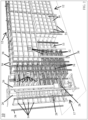
FIG. 1 is a perspective view of a multiple temperature automated storage system shown with an insulated enclosure surrounding a portion of the system; -
FIG. 2 is another perspective view of a multiple temperature automated storage system ofFIG. 1 , shown with the insulated enclosure and a portion of storage positions removed to reveal details of the storage positions and shuttle rails inside the insulated enclosure; -
FIG. 3 is a front perspective view of the multiple temperature automated storage system ofFIG. 1 , shown with the insulated enclosure; -
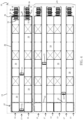
FIG. 4 is a top plan view of a multiple temperature automated storage system in accordance with the present invention, -
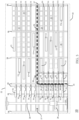
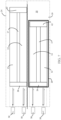
FIG. 5 is a side elevation of the multiple temperature automated storage system ofFIG. 1 ; -
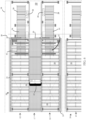
FIG. 6 is an enlarged top plan view of the multiple temperature automated storage system ofFIG. 1 ; and -
FIG. 7 is a diagram of a multiple temperature automated storage system and method. - Referring now to the drawings and the illustrative embodiments depicted therein, a multiple temperature automated storage system and
method 10 includes a pair of spaced apart racks 12 havingmultiple levels 14 of shelves definingitem storage positons 16 and anaisle 17 at each level. Theaisle 17 is disposed between the pair of space apart racks 12 (FIGS. 1-4 ). A plurality ofshuttles 15 are adapted to operate inaisles 17 for storing items to thestorage positons 16 and retrieving items from thestorage positons 16. Eachshuttle 15 is adapted to store items to or retrieve items fromstorage positions 16 on either side ofaisle 17. Alift 26 including a verticallymoveable platform 28, supplies items to and retrieves items fromparticular levels 14 of therack 12 for theshuttles 15 to store to thestorage positons 16 and retrieve items from the storage positons 16 (FIGS. 1-3 ). Such automated storage system, or warehouse, may be of the type disclosed in commonly assignedU.S. Patent No. 9,630,777 enclosure 20 encloses some of thelevels 14 of therack 12 to define alow temperature zone 18 in order to store, for example, frozen items (FIGS. 1 and5 ). The remaininglevels 14 of the rack defining ahigher temperature zone 22, in order to store, for example, chilled items. A refrigeration system (not shown) lowers the temperature in lower orfrozen temperature zone 18. Eachrack 12 is in achilled room 19 at a temperature defining the temperature of higher or chilledtemperature zone 22. Additional pairs ofracks 13 may be installed adjacent to the pair ofracks 12, and the additional racks may be maintained at higher orambient temperature zone 24 to store, for example, items that do not require any form of refrigeration (FIGS. 4 and6 ).Ambient temperature zone 24 may be the same temperature ashigher temperature zone 22. - The
lift 26 is located on the outside of the thermally insulatedenclosure 20 and is substantially entirely within chilled temperature zone 22 (FIGS. 1 ,3 , and4-5 ). Amoveable air barrier 30 is included betweenlift 26 and thermally insulated enclosure 20 (FIGS. 1 and3 ).Lift 26 supplies items to and retrieves items from the thermally insulatedenclosure 20 throughair barrier 30. While theair barrier 30 illustrated inFIGS. 1 and3 is a door, other embodiments are contemplated, including air curtains, an "air knife", or the like. Typically, oneair barrier 30 is be provided for each level 14 (FIG. 5 ). Theair barrier 30 may be adapted to provide an opening for items or totes to pass from thefrozen zone 18 to the chilledzone 22 through theinsulated enclosure 20. The opening may remain open for the duration of an operating period when the multiple temperature automatedstorage system 10 is operating and be closed when thesystem 10 is not operating. Under such operating conditions, theair barrier 30 may include an air-knife to limit the air from the chilledzone 22 from entering into thefreezer zone 18. Alternatively, theair barrier 30 may be adapted to open and close only when an item or tote needs to enter or leave theinsulated enclosure 20. - Due to the temperature differences between the
freezer zone 18 and the chilledzone 22, condensation may occur on theshuttle 15 if theshuttle 15 moves between the freezingzone 18 and the chilledzone 22 orambient zone 24. In order to reduce or eliminate condensation, theshuttle 15 inside the thermally insulatedenclosure 20 is not able to exit theenclosure 20. In this manner, there is a great reduction in the amount of frost build up on the equipment or items. An additional orsupplemental shuttle 15a may be operably stored inside the thermally insulatedenclosure 20, such that if themain shuttle 15 malfunctions or requires maintenance, the supplemental shuttle can take over for themain shuttle 15 without being susceptible to any significant condensation (FIGS. 4-5 ). Amaintenance access area 42 may be provided at a back portion of therack 12 and inside of the insulated enclosure 20 (FIG. 4 ). Thesupplemental shuttle 15a may be stored or staged in themaintenance access area 42 such that it does not interfere with operation of theshuttle 15 operating in theaisle 17. - An
interior buffer conveyer 32 is provided inside the thermally insulatedenclosure 20 adjacent theair barrier 30 for buffering items retrieved for storage by ashuttle 15 or retrieved from storage by the shuttle 15 (FIGS. 2 and4-6 ). Theshuttles 15 disposed inside of the insulated enclosure move items between thestorage locations 16 and theinterior buffer conveyor 32 to store the items in therack 12 or to retrieve them from therack 12. Theinterior buffer conveyor 32 receives items from theshuttle 15 and moves them through theair barrier 30 to anexterior buffer conveyor 34 that is outside of theinsulated enclosure 20, or theinterior buffer conveyor 32 receives items from theexterior buffer conveyor 34 through theair barrier 30 and moves them to theshuttle 15 to be stored in therack 12. In the case of thehigher temperature zone 22, theshuttle 15 can directly access theexterior buffer conveyor 34 at a particular level to retrieve or place items. Thus, nointerior buffer conveyor 32 is needed in the levels outside of theinsulated enclosure 20. Theexterior buffer conveyor 34 is provided betweenlift 26 and the air barrier for buffering items supplied by the lift or awaiting retrieval by the lift 26 (FIGS. 1-6 ). In this manner, lift 26 can operate independently of theshuttles 15 and vice versa. Items are transported throughair barrier 30 bybuffer conveyors - The
insulated enclosure 20 includes insulatedwalls 35 surrounding thefreezer zone 18 to retain the frozen air inside of the freezer zone 18 (FIG. 1 ). An insulated upper surface orceiling 36 ofenclosure 20 is positioned betweenlevels 14 of therack 12. Theinsulated enclosure 20 can be positioned to enclose more orfewer levels 14 of therack 12 as required due to volume and space requirements for frozen items. Theupper surface 36 and thewall panels 35 can be reconfigured or replaced in order to increase or decrease the size ofenclosure 20 if the space and volumes needs for frozen items change. The insulatedupper surface 36 is typically disposed in amaintenance space 37 between twolevels 14 of the rack 12 (seeFIGS. 3 and5 ). Themaintenance space 37 allows a user or technician an access space to perform maintenance on a portion of therack 12 without removal items from the storage positions 16. Themaintenance space 37 may be provided at intervals betweenlevels 14, such as if every fifth level includes amaintenance space 37. Theinsulated enclosure 20 can thus be fixed at a height corresponding to themaintenance space 37, and can later be reconfigured to increase or decrease the volume of thefreezer zone 18 as required for storage of inventory, according to the spacing of themaintenance spaces 37. Theinsulated enclosure 20 encloses themaintenance access area 42 at the back of therack 12. - The
freezer zone 18 is located below the chilledzone 22 because the density of frozen air is higher than the density of the chilled air, and the denser frozen air sinks below the chilled air, therefore it is most efficient to locate thefreezer zone 18 below the chilledzone 22. The chilledzone 22 is provisioned above thefrozen zone 18 usingcommon uprights 38 that penetrate thethermal barrier 20 between the chilledzone 22 and frozen zone 18 (FIGS. 1 and5 ). Theuprights 38 may include insulation or shielding around theuprights 38 at least at the intersection between theupper surface 36 and the upright 38 to reduce heat transfer between the chilledzone 22 and thefreezer zone 18 through theupright 38. - A
pick station 50 may be included with the multiple temperature automatedstorage system 10 to pick items stored to or received from the system 10 (FIG. 7 ). Eachrack 12 may include apick station 50. Thepick station 50 may include a goods-to-person pick station or a goods-to-robot pick station. An exemplary pick station is disclosed in commonly assignedU.S. Patent No. 10,301,113 - Thus, chilled and frozen products can be stored in the smallest possible space inside of a warehouse, distribution center, or store with storage increments less than one aisle of shuttle or full storage rack. The multiple temperature automated storage system provides efficient temperature control of products in an automated storage system without having to provide an independent storage space for chilled products and frozen products. The multiple temperature automated storage system can be located adjacent to an automated storage system or rack that is maintained at an ambient air temperature. Shuttles that operate in the freezer zone are limited to operation only inside the freezer zone and shuttles that operate in the chilled zone are limited to operation only inside the chilled zone. The limitation on operation zone reduces the risk of malfunction or failure of the shuttle due to condensation and/or frost.
Claims (13)
- A multiple temperature automated storage system (10), comprising:a rack (12) having multiple levels (14) of shelves defining item storage positions (16) and an aisle (17) at each level;a plurality of shuttles (15) adapted to operate in said aisles (17) for storing items to said storage positions (16) and retrieving items from said storage positions (16); and a thermally insulated enclosure (20) enclosing some of said levels (14) of said rack (12) to define a low temperature zone (18) with the remaining levels (14) of said rack defining a higher temperature zone (22), further comprising a refrigeration system to lower the temperature in said lower temperature zone (18), characterised in that some of said shuttles (15) are limited to operation within said thermally insulated enclosure (20) and other of said shuttles (15) are limited to operation outside of said thermally insulated enclosure (20).
- The automated storage system as claimed in claim 1 wherein said rack (12) is in a room (19) at a temperature defining the temperature of said higher temperature zone (22).
- The automated storage system as claimed in claim 1 including a lift (26) for supplying items to and retrieving items from particular levels (14) of said rack (12), said lift comprises a platform (28) configured to receive and support the items supplied to and retrieved from said particular levels (14), said platform (28) is selectively operable to raise and lower relative to said levels (14) of said rack (12).
- The automated storage system as claimed in claim 3, wherein said lift (26) is substantially entirely within the higher temperature zone (22), preferably including a moveable air barrier (30) disposed through said thermally insulated enclosure (20) proximate said lift (26), said platform of said lift (26) supplying items to and retrieving items from said thermally insulated enclosure (20) through said air barrier (30).
- The automated storage system as claimed in claim 4 including a moveable air barrier (30) disposed through said thermally insulated enclosure (20) proximate said lift (26), said platform (28) of said lift (26) supplying items to and retrieving items from said thermally insulated enclosure (20) through said air barrier (30) and including a first buffer conveyer (32) inside said thermally insulated enclosure (20) adjacent said air barrier (30) for buffering items for storage by a shuttle (15) or retrieved from storage by the shuttle (15), optionally including a second buffer conveyor (34) outside said thermally insulated enclosure (20) adjacent said air barrier (20) for buffering items supplied from outside said thermally insulated enclosure (20) or awaiting retrieval at the outside of said thermally insulated enclosure (20).
- The automated storage system as claimed in claim 1, further comprising a second rack (13) having multiple levels (14) of shelves defining item storage positions (16), said second rack parallel to said rack (12) and separated from said rack by said aisle (17), wherein said plurality of shuttles (15) are operable to store items to said storage positions (16) and retrieving items from said storage positions (16) in said rack (12) and said second rack (13).
- The automated storage system as claimed in claim 1, further comprising a supplemental shuttle (15a) operably disposed inside of said thermally insulated enclosure (20) to take over for one of said shuttles (15) in the event that one of said shuttles (15) is no longer operable, preferably said supplemental shuttle (15a) is operably disposed in a maintenance space (42) that is located inside of a portion of said thermally insulated enclosure (20), such that said supplemental shuttle (15a) does not interfere with operation of said shuttle (15).
- The automated storage system as claimed in claim 1, wherein said thermally insulated enclosure (20) comprises an insulating layer (35, 36) disposed inside of a maintenance level (37) of said rack, said maintenance level defining a maintenance access to allow an operator to perform maintenance on a portion of said rack (12).
- The automated storage system as claimed in claim 1, further comprising another rack and another plurality of shuttles that are disposed adjacent to said rack of said automated storage and retrieval system, said another rack and said another shuttles are located in a portion of the room at a temperature defining the temperature of another temperature zone, preferably the temperature of said another temperature zone is equal to the ambient temperature of the room.
- A method of storing items at two different temperatures in a common automated storage system, comprising:having a rack (12) including multiple levels (14) of shelves defining item storage positions (16) with an aisle (17) at each level;having a plurality of shuttles (15) operating in said aisles (17), said shuttles storing items to said storage positions (16) and retrieving items from said storage positions (16); andhaving a thermally insulated enclosure (20) enclosing some of said levels (14) of said rack (12) to define a low temperature zone (18) with the remaining levels of said rack defining a higher temperature zone (22), further comprising a refrigeration system to lower the temperature in said lower temperature zone (18), characterised in that some of said shuttles (15) are limited to operating in said low temperature zone (18) within said thermally insulated enclosure (20) and other of said shuttles (15) are limited to operation in said higher temperature zone (22) outside of said thermally insulated enclosure (20).
- The method as claimed in claim 10 including a lift (26) for supplying items to and retrieving items from particular of said levels (14) of said rack (12), said lift (26) comprising a platform (28) configured to receive and support the items supplied to and retrieved from said particular levels (14), said platform (28) is selectively operable to raise and lower relative to said levels (14) of said rack (12).
- The method as claimed in claim 11, wherein said lift (26) is substantially entirely within said higher temperature zone (22), preferably including a moveable air barrier (30) disposed through said thermally insulated enclosure (20) proximate said lift (26), said platform of said lift supplying items to and retrieving items from said thermally insulated enclosure (20) through said air barrier (30).
- The method as claimed in claim 12 including a moveable air barrier (30) disposed through said thermally insulated enclosure (20) proximate said lift (26), said platform (28) of said lift (26) supplying items to and retrieving items from said thermally insulated enclosure (20) through said air barrier (30) and including a first buffer conveyer (32) inside said thermally insulated enclosure (20) adjacent said air barrier (30) and a particular level (14) of said rack (12) for buffering items for storage by a shuttle (15) at that particular level or retrieved from storage by the shuttle (15) at that particular level, optionally including a second buffer conveyor (34) outside said thermally insulated enclosure (20) adjacent said air barrier (30) and a particular level of said rack for buffering items supplied by said platform (28) of said lift (26) or awaiting retrieval by said platform of said lift (26) proximate that particular level (14) of said rack (12).
Applications Claiming Priority (2)
| Application Number | Priority Date | Filing Date | Title |
|---|---|---|---|
| US201862772408P | 2018-11-28 | 2018-11-28 | |
| PCT/IB2019/060249 WO2020110041A1 (en) | 2018-11-28 | 2019-11-27 | Multiple temperature automated storage system and method |
Publications (3)
| Publication Number | Publication Date |
|---|---|
| EP3887288A1 EP3887288A1 (en) | 2021-10-06 |
| EP3887288A4 EP3887288A4 (en) | 2022-08-10 |
| EP3887288B1 true EP3887288B1 (en) | 2024-08-07 |
Family
ID=70771610
Family Applications (1)
| Application Number | Title | Priority Date | Filing Date |
|---|---|---|---|
| EP19888410.8A Active EP3887288B1 (en) | 2018-11-28 | 2019-11-27 | Multiple temperature automated storage system and method |
Country Status (6)
| Country | Link |
|---|---|
| US (1) | US11067329B2 (en) |
| EP (1) | EP3887288B1 (en) |
| CN (1) | CN113165802B (en) |
| AU (2) | AU2019387390B2 (en) |
| ES (1) | ES2989116T3 (en) |
| WO (1) | WO2020110041A1 (en) |
Families Citing this family (17)
| Publication number | Priority date | Publication date | Assignee | Title |
|---|---|---|---|---|
| CN111021783A (en) * | 2019-12-20 | 2020-04-17 | 贵州翰凯斯智能技术有限公司 | A functionally scalable housing structure |
| US11685588B2 (en) * | 2020-03-26 | 2023-06-27 | Walmart Apollo, Llc | Tote handling for chilled or frozen goods |
| PL243727B1 (en) * | 2020-04-27 | 2023-10-02 | Retail Robotics Spolka Z Ograniczona Odpowiedzialnoscia Spolka Komandytowa | An automated device for storing and receiving food products purchased in a mail-order transaction via the Internet |
| IT202000009502A1 (en) * | 2020-04-30 | 2021-10-30 | System Logistics S P A | ELEVATOR FOR AUTOMATIC STORAGE SYSTEMS |
| WO2022155236A2 (en) * | 2021-01-12 | 2022-07-21 | Alert Innovation Inc. | Transport rack and transport rack docking interface |
| DE102021004093A1 (en) * | 2021-08-10 | 2023-02-16 | Knapp Smart Solutions Gmbh | Method for repairing an order-picking device |
| DE102021129397B3 (en) | 2021-11-11 | 2023-01-26 | Ssi Schäfer Automation Gmbh (At) | Automated storage system with multiple climate zones |
| PL439611A1 (en) * | 2021-11-23 | 2023-05-29 | Veloxalpha Spółka Akcyjna | Nano-warehouse for storing products and parcels with the creating cargo units and picking of orders, method of moving containers with products in a nano-warehouse and method of order picking in a nano-warehouse |
| NO347235B1 (en) * | 2022-01-07 | 2023-07-24 | Autostore Tech As | Variable temperature zone in a storage and retrieval system |
| CA3243285A1 (en) * | 2022-01-31 | 2023-08-03 | Dematic Corp. | Receptacle with temperature controlled lid for automated storage and retrieval system |
| GB202300771D0 (en) | 2022-01-31 | 2023-03-08 | Dematic Corp | Automated storage and retrieval system and microclimate-controlled receptacles for pharmaceuticals and method for operating same |
| EP4529606A1 (en) * | 2022-05-23 | 2025-04-02 | Ocado Innovation Limited | Multi-temperature storage system |
| GB2619027B (en) * | 2022-05-23 | 2024-09-18 | Ocado Innovation Ltd | Multi-temperature storage system |
| CN115676224B (en) * | 2022-09-19 | 2026-01-02 | 未来机器人(深圳)有限公司 | Cargo production scheduling methods and handling equipment |
| EP4353630B1 (en) | 2022-10-13 | 2025-03-05 | Dematic GmbH | Storage system with a multi-level storage rack |
| WO2025085562A1 (en) * | 2023-10-16 | 2025-04-24 | SIMPL Automation Inc. | Load handling system for storage racking |
| GB2638700A (en) * | 2024-02-28 | 2025-09-03 | Ocado Innovation Ltd | Storage and retrieval system |
Citations (7)
| Publication number | Priority date | Publication date | Assignee | Title |
|---|---|---|---|---|
| EP0780643A2 (en) | 1995-12-22 | 1997-06-25 | Siemens Aktiengesellschaft | Store for common storage of uncooled and cooled goods |
| DE102013102778A1 (en) | 2013-03-19 | 2014-09-25 | Dematic Accounting Services Gmbh | Shelf storage with a frozen and / or inertized storage area |
| WO2015159139A1 (en) | 2014-04-14 | 2015-10-22 | Razumov Sergey N | Robotic pickup point for order fulfillment system |
| EP2949604A1 (en) | 2014-05-28 | 2015-12-02 | Dematic Systems GmbH | Method of commissioning in a storage facility having a plurality of lifts |
| DE102014112994A1 (en) | 2014-09-09 | 2016-03-10 | Ludwig Brandmüller | order picking |
| WO2016191777A1 (en) | 2015-05-29 | 2016-12-08 | Tgw Mechanics Gmbh | Transport vehicle and method for storing or removing piece goods, and storage system |
| DE102017110373A1 (en) | 2017-05-12 | 2018-11-15 | Witron Logistik + Informatik Gmbh | GOODS EXTRACTING BUFFER FOR A COMMISSIONING SYSTEM |
Family Cites Families (28)
| Publication number | Priority date | Publication date | Assignee | Title |
|---|---|---|---|---|
| JPS56155362A (en) * | 1980-04-30 | 1981-12-01 | Daifuku Machinery Works | Cold storage facility with load carry-in/out device |
| KR920006442B1 (en) * | 1986-12-25 | 1992-08-06 | 가부시기가이샤 이도오기 고오사꾸쇼 | Device for automatic storage of goods |
| US5167575A (en) * | 1989-08-23 | 1992-12-01 | Macdonald Ross P | Clean room including an internal partition system |
| DE10009396C1 (en) | 2000-02-28 | 2001-06-28 | Siemens Ag | Storage device for warm and cold items e.g. for use in food industry |
| DE10011205B4 (en) * | 2000-03-08 | 2010-09-02 | Voith Patent Gmbh | Warehouses, especially high-bay warehouses |
| US20070065259A1 (en) * | 2005-08-30 | 2007-03-22 | Talley Paul A | Automated self storage system |
| JP4798429B2 (en) * | 2005-10-03 | 2011-10-19 | 株式会社ダイフク | Goods transport equipment |
| EP1939561A3 (en) * | 2006-12-07 | 2008-07-23 | Tecan Trading AG | Compact bearing element and its use |
| JP5126591B2 (en) * | 2008-03-04 | 2013-01-23 | 株式会社ダイフク | Goods storage equipment |
| ES2606514T3 (en) | 2011-09-28 | 2017-03-24 | Dematic Gmbh | Automated multi-level storage |
| EP2826730A1 (en) * | 2013-07-17 | 2015-01-21 | Dematic Accounting Services GmbH | Method of order fulfilling by preparing storage units at a picking station |
| WO2016007940A1 (en) | 2014-07-11 | 2016-01-14 | Dematic Corp. | Picking station with automated warehouse |
| US10124341B2 (en) * | 2014-09-22 | 2018-11-13 | Liconic Ag | Low-temperature storage device with cassette handler |
| FR3034622B1 (en) * | 2015-04-13 | 2017-05-19 | Ynsect | INSECT BREEDING WORKSHOP |
| WO2016196815A1 (en) * | 2015-06-02 | 2016-12-08 | Alert Corporation | Storage and retrieval system |
| GB201509661D0 (en) * | 2015-06-03 | 2015-07-15 | Ocado Innovation Ltd | Temperature controlled storage system |
| US10202240B2 (en) * | 2015-06-23 | 2019-02-12 | Iron Mountain Incorporated | Storage system |
| PL413365A1 (en) | 2015-07-31 | 2017-02-13 | JBG-2 Spółka z Ograniczoną Odpowiedzialnością | Storing device |
| NO20160075A1 (en) * | 2016-01-14 | 2017-04-03 | Autostore Tech As | Method for retrieving items from a storage system and storage system for storing and retrieving bins |
| MX2019005740A (en) * | 2016-11-17 | 2019-09-11 | Alert Innovation Inc | SYSTEM AND SALES METHOD OF AUTOMATED SERVICE. |
| CA3044850A1 (en) * | 2016-11-29 | 2018-06-07 | Alert Innovation Inc. | Automated retail supply chain and inventory management system |
| CN107054958B (en) * | 2017-03-29 | 2020-01-03 | 深圳逗号互联科技有限公司 | Modular warehousing system |
| EP3415005B1 (en) * | 2017-06-16 | 2022-08-03 | Liconic Ag | Automatic blood bank |
| CN107902313B (en) | 2017-12-14 | 2024-02-09 | 长沙迈迪克智能科技有限公司 | Automatic control method and storage management device based on vaccine storage and management |
| CN108502431B (en) * | 2018-03-30 | 2020-05-19 | 中铁第四勘察设计院集团有限公司 | Cold chain warehouse with temperature zones and goods storage method |
| US10769587B2 (en) * | 2018-07-02 | 2020-09-08 | Walmart Apollo, Llc | Systems and methods of storing and retrieving retail store product inventory |
| US11332311B2 (en) * | 2018-08-30 | 2022-05-17 | Alert Innovation Inc. | Tote handling for chilled or frozen goods |
| US10934918B1 (en) * | 2019-10-14 | 2021-03-02 | Paccar Inc | Combined urea hydrolysis and selective catalytic reduction for emissions control |
-
2019
- 2019-11-27 EP EP19888410.8A patent/EP3887288B1/en active Active
- 2019-11-27 AU AU2019387390A patent/AU2019387390B2/en active Active
- 2019-11-27 ES ES19888410T patent/ES2989116T3/en active Active
- 2019-11-27 US US16/697,468 patent/US11067329B2/en active Active
- 2019-11-27 WO PCT/IB2019/060249 patent/WO2020110041A1/en not_active Ceased
- 2019-11-27 CN CN201980075878.2A patent/CN113165802B/en active Active
-
2024
- 2024-06-18 AU AU2024204143A patent/AU2024204143A1/en active Pending
Patent Citations (7)
| Publication number | Priority date | Publication date | Assignee | Title |
|---|---|---|---|---|
| EP0780643A2 (en) | 1995-12-22 | 1997-06-25 | Siemens Aktiengesellschaft | Store for common storage of uncooled and cooled goods |
| DE102013102778A1 (en) | 2013-03-19 | 2014-09-25 | Dematic Accounting Services Gmbh | Shelf storage with a frozen and / or inertized storage area |
| WO2015159139A1 (en) | 2014-04-14 | 2015-10-22 | Razumov Sergey N | Robotic pickup point for order fulfillment system |
| EP2949604A1 (en) | 2014-05-28 | 2015-12-02 | Dematic Systems GmbH | Method of commissioning in a storage facility having a plurality of lifts |
| DE102014112994A1 (en) | 2014-09-09 | 2016-03-10 | Ludwig Brandmüller | order picking |
| WO2016191777A1 (en) | 2015-05-29 | 2016-12-08 | Tgw Mechanics Gmbh | Transport vehicle and method for storing or removing piece goods, and storage system |
| DE102017110373A1 (en) | 2017-05-12 | 2018-11-15 | Witron Logistik + Informatik Gmbh | GOODS EXTRACTING BUFFER FOR A COMMISSIONING SYSTEM |
Also Published As
| Publication number | Publication date |
|---|---|
| US11067329B2 (en) | 2021-07-20 |
| EP3887288A1 (en) | 2021-10-06 |
| WO2020110041A1 (en) | 2020-06-04 |
| AU2019387390A1 (en) | 2021-05-20 |
| EP3887288A4 (en) | 2022-08-10 |
| CN113165802A (en) | 2021-07-23 |
| CN113165802B (en) | 2022-12-23 |
| AU2019387390B2 (en) | 2024-05-09 |
| ES2989116T3 (en) | 2024-11-25 |
| AU2024204143A1 (en) | 2024-07-04 |
| US20200166267A1 (en) | 2020-05-28 |
Similar Documents
| Publication | Publication Date | Title |
|---|---|---|
| EP3887288B1 (en) | Multiple temperature automated storage system and method | |
| US10202240B2 (en) | Storage system | |
| EP3645426B1 (en) | Automated storage and retrieval system comprising different temperature zones | |
| CN111942787B (en) | Self-service miscellaneous goods storing and taking terminal and device for moving miscellaneous goods box in same | |
| JP2021535052A (en) | Handling of totes for refrigerated or frozen products | |
| EP2382430B1 (en) | Dual temperature automated storage and retrieval system | |
| US9297570B2 (en) | Rack-aisle freezing system for palletized product | |
| JP2023519607A (en) | Automated storage system with storage tower in isolation enclosure | |
| US20170029210A1 (en) | Storage device | |
| US20110107784A1 (en) | Apparatus for blast freezing palletized product | |
| US12163721B2 (en) | Automated storage system including multiple climate zones | |
| EP4448416A1 (en) | System and method of temperature control in an automated grid based storage and retrieval system | |
| US11988435B2 (en) | Automated blast cell loading and unloading | |
| AU2009203064B2 (en) | Air flow control method and system | |
| KR970001298B1 (en) | Constructional things for a refrigerator | |
| JP2000238903A (en) | Storing and collecting system for articles | |
| WO2025165534A1 (en) | Chilled and frozen storage zones in commercial product storage structures | |
| EP4589223A1 (en) | An airflow control device | |
| NO20230863A1 (en) | An automated storage and retrieval system comprising a temperature management system and a method for managing temperature in the automated storage and retrieval system | |
| JP2025075683A (en) | Automated transport multi-storey warehouse and warehouse system |
Legal Events
| Date | Code | Title | Description |
|---|---|---|---|
| STAA | Information on the status of an ep patent application or granted ep patent |
Free format text: STATUS: THE INTERNATIONAL PUBLICATION HAS BEEN MADE |
|
| PUAI | Public reference made under article 153(3) epc to a published international application that has entered the european phase |
Free format text: ORIGINAL CODE: 0009012 |
|
| STAA | Information on the status of an ep patent application or granted ep patent |
Free format text: STATUS: REQUEST FOR EXAMINATION WAS MADE |
|
| 17P | Request for examination filed |
Effective date: 20210531 |
|
| AK | Designated contracting states |
Kind code of ref document: A1 Designated state(s): AL AT BE BG CH CY CZ DE DK EE ES FI FR GB GR HR HU IE IS IT LI LT LU LV MC MK MT NL NO PL PT RO RS SE SI SK SM TR |
|
| DAV | Request for validation of the european patent (deleted) | ||
| DAX | Request for extension of the european patent (deleted) | ||
| A4 | Supplementary search report drawn up and despatched |
Effective date: 20220708 |
|
| RIC1 | Information provided on ipc code assigned before grant |
Ipc: F25D 23/06 20060101ALI20220704BHEP Ipc: F25D 25/04 20060101ALI20220704BHEP Ipc: F25D 25/02 20060101ALI20220704BHEP Ipc: F25D 13/06 20060101ALI20220704BHEP Ipc: F25D 13/04 20060101ALI20220704BHEP Ipc: F25D 13/02 20060101ALI20220704BHEP Ipc: B65G 1/137 20060101ALI20220704BHEP Ipc: B65G 1/04 20060101AFI20220704BHEP |
|
| GRAP | Despatch of communication of intention to grant a patent |
Free format text: ORIGINAL CODE: EPIDOSNIGR1 |
|
| STAA | Information on the status of an ep patent application or granted ep patent |
Free format text: STATUS: GRANT OF PATENT IS INTENDED |
|
| GRAJ | Information related to disapproval of communication of intention to grant by the applicant or resumption of examination proceedings by the epo deleted |
Free format text: ORIGINAL CODE: EPIDOSDIGR1 |
|
| STAA | Information on the status of an ep patent application or granted ep patent |
Free format text: STATUS: REQUEST FOR EXAMINATION WAS MADE |
|
| INTG | Intention to grant announced |
Effective date: 20240515 |
|
| GRAS | Grant fee paid |
Free format text: ORIGINAL CODE: EPIDOSNIGR3 |
|
| STAA | Information on the status of an ep patent application or granted ep patent |
Free format text: STATUS: GRANT OF PATENT IS INTENDED |
|
| GRAP | Despatch of communication of intention to grant a patent |
Free format text: ORIGINAL CODE: EPIDOSNIGR1 |
|
| INTC | Intention to grant announced (deleted) | ||
| GRAA | (expected) grant |
Free format text: ORIGINAL CODE: 0009210 |
|
| STAA | Information on the status of an ep patent application or granted ep patent |
Free format text: STATUS: THE PATENT HAS BEEN GRANTED |
|
| INTG | Intention to grant announced |
Effective date: 20240624 |
|
| AK | Designated contracting states |
Kind code of ref document: B1 Designated state(s): AL AT BE BG CH CY CZ DE DK EE ES FI FR GB GR HR HU IE IS IT LI LT LU LV MC MK MT NL NO PL PT RO RS SE SI SK SM TR |
|
| REG | Reference to a national code |
Ref country code: GB Ref legal event code: FG4D |
|
| REG | Reference to a national code |
Ref country code: CH Ref legal event code: EP |
|
| REG | Reference to a national code |
Ref country code: IE Ref legal event code: FG4D |
|
| REG | Reference to a national code |
Ref country code: DE Ref legal event code: R096 Ref document number: 602019056778 Country of ref document: DE |
|
| P01 | Opt-out of the competence of the unified patent court (upc) registered |
Free format text: CASE NUMBER: APP_50583/2024 Effective date: 20240906 |
|
| REG | Reference to a national code |
Ref country code: NL Ref legal event code: FP |
|
| REG | Reference to a national code |
Ref country code: LT Ref legal event code: MG9D Ref country code: ES Ref legal event code: FG2A Ref document number: 2989116 Country of ref document: ES Kind code of ref document: T3 Effective date: 20241125 |
|
| REG | Reference to a national code |
Ref country code: AT Ref legal event code: UEP Ref document number: 1710711 Country of ref document: AT Kind code of ref document: T Effective date: 20240807 |
|
| PG25 | Lapsed in a contracting state [announced via postgrant information from national office to epo] |
Ref country code: NO Free format text: LAPSE BECAUSE OF FAILURE TO SUBMIT A TRANSLATION OF THE DESCRIPTION OR TO PAY THE FEE WITHIN THE PRESCRIBED TIME-LIMIT Effective date: 20241107 |
|
| PG25 | Lapsed in a contracting state [announced via postgrant information from national office to epo] |
Ref country code: FI Free format text: LAPSE BECAUSE OF FAILURE TO SUBMIT A TRANSLATION OF THE DESCRIPTION OR TO PAY THE FEE WITHIN THE PRESCRIBED TIME-LIMIT Effective date: 20240807 Ref country code: GR Free format text: LAPSE BECAUSE OF FAILURE TO SUBMIT A TRANSLATION OF THE DESCRIPTION OR TO PAY THE FEE WITHIN THE PRESCRIBED TIME-LIMIT Effective date: 20241108 Ref country code: PL Free format text: LAPSE BECAUSE OF FAILURE TO SUBMIT A TRANSLATION OF THE DESCRIPTION OR TO PAY THE FEE WITHIN THE PRESCRIBED TIME-LIMIT Effective date: 20240807 Ref country code: PT Free format text: LAPSE BECAUSE OF FAILURE TO SUBMIT A TRANSLATION OF THE DESCRIPTION OR TO PAY THE FEE WITHIN THE PRESCRIBED TIME-LIMIT Effective date: 20241209 |
|
| PG25 | Lapsed in a contracting state [announced via postgrant information from national office to epo] |
Ref country code: BG Free format text: LAPSE BECAUSE OF FAILURE TO SUBMIT A TRANSLATION OF THE DESCRIPTION OR TO PAY THE FEE WITHIN THE PRESCRIBED TIME-LIMIT Effective date: 20240807 |
|
| PG25 | Lapsed in a contracting state [announced via postgrant information from national office to epo] |
Ref country code: LV Free format text: LAPSE BECAUSE OF FAILURE TO SUBMIT A TRANSLATION OF THE DESCRIPTION OR TO PAY THE FEE WITHIN THE PRESCRIBED TIME-LIMIT Effective date: 20240807 |
|
| PG25 | Lapsed in a contracting state [announced via postgrant information from national office to epo] |
Ref country code: IS Free format text: LAPSE BECAUSE OF FAILURE TO SUBMIT A TRANSLATION OF THE DESCRIPTION OR TO PAY THE FEE WITHIN THE PRESCRIBED TIME-LIMIT Effective date: 20241207 |
|
| PG25 | Lapsed in a contracting state [announced via postgrant information from national office to epo] |
Ref country code: HR Free format text: LAPSE BECAUSE OF FAILURE TO SUBMIT A TRANSLATION OF THE DESCRIPTION OR TO PAY THE FEE WITHIN THE PRESCRIBED TIME-LIMIT Effective date: 20240807 |
|
| PG25 | Lapsed in a contracting state [announced via postgrant information from national office to epo] |
Ref country code: RS Free format text: LAPSE BECAUSE OF FAILURE TO SUBMIT A TRANSLATION OF THE DESCRIPTION OR TO PAY THE FEE WITHIN THE PRESCRIBED TIME-LIMIT Effective date: 20241107 |
|
| PG25 | Lapsed in a contracting state [announced via postgrant information from national office to epo] |
Ref country code: RS Free format text: LAPSE BECAUSE OF FAILURE TO SUBMIT A TRANSLATION OF THE DESCRIPTION OR TO PAY THE FEE WITHIN THE PRESCRIBED TIME-LIMIT Effective date: 20241107 Ref country code: PT Free format text: LAPSE BECAUSE OF FAILURE TO SUBMIT A TRANSLATION OF THE DESCRIPTION OR TO PAY THE FEE WITHIN THE PRESCRIBED TIME-LIMIT Effective date: 20241209 Ref country code: PL Free format text: LAPSE BECAUSE OF FAILURE TO SUBMIT A TRANSLATION OF THE DESCRIPTION OR TO PAY THE FEE WITHIN THE PRESCRIBED TIME-LIMIT Effective date: 20240807 Ref country code: NO Free format text: LAPSE BECAUSE OF FAILURE TO SUBMIT A TRANSLATION OF THE DESCRIPTION OR TO PAY THE FEE WITHIN THE PRESCRIBED TIME-LIMIT Effective date: 20241107 Ref country code: LV Free format text: LAPSE BECAUSE OF FAILURE TO SUBMIT A TRANSLATION OF THE DESCRIPTION OR TO PAY THE FEE WITHIN THE PRESCRIBED TIME-LIMIT Effective date: 20240807 Ref country code: IS Free format text: LAPSE BECAUSE OF FAILURE TO SUBMIT A TRANSLATION OF THE DESCRIPTION OR TO PAY THE FEE WITHIN THE PRESCRIBED TIME-LIMIT Effective date: 20241207 Ref country code: HR Free format text: LAPSE BECAUSE OF FAILURE TO SUBMIT A TRANSLATION OF THE DESCRIPTION OR TO PAY THE FEE WITHIN THE PRESCRIBED TIME-LIMIT Effective date: 20240807 Ref country code: GR Free format text: LAPSE BECAUSE OF FAILURE TO SUBMIT A TRANSLATION OF THE DESCRIPTION OR TO PAY THE FEE WITHIN THE PRESCRIBED TIME-LIMIT Effective date: 20241108 Ref country code: FI Free format text: LAPSE BECAUSE OF FAILURE TO SUBMIT A TRANSLATION OF THE DESCRIPTION OR TO PAY THE FEE WITHIN THE PRESCRIBED TIME-LIMIT Effective date: 20240807 Ref country code: BG Free format text: LAPSE BECAUSE OF FAILURE TO SUBMIT A TRANSLATION OF THE DESCRIPTION OR TO PAY THE FEE WITHIN THE PRESCRIBED TIME-LIMIT Effective date: 20240807 |
|
| PG25 | Lapsed in a contracting state [announced via postgrant information from national office to epo] |
Ref country code: RO Free format text: LAPSE BECAUSE OF FAILURE TO SUBMIT A TRANSLATION OF THE DESCRIPTION OR TO PAY THE FEE WITHIN THE PRESCRIBED TIME-LIMIT Effective date: 20240807 Ref country code: DK Free format text: LAPSE BECAUSE OF FAILURE TO SUBMIT A TRANSLATION OF THE DESCRIPTION OR TO PAY THE FEE WITHIN THE PRESCRIBED TIME-LIMIT Effective date: 20240807 Ref country code: SM Free format text: LAPSE BECAUSE OF FAILURE TO SUBMIT A TRANSLATION OF THE DESCRIPTION OR TO PAY THE FEE WITHIN THE PRESCRIBED TIME-LIMIT Effective date: 20240807 |
|
| PG25 | Lapsed in a contracting state [announced via postgrant information from national office to epo] |
Ref country code: EE Free format text: LAPSE BECAUSE OF FAILURE TO SUBMIT A TRANSLATION OF THE DESCRIPTION OR TO PAY THE FEE WITHIN THE PRESCRIBED TIME-LIMIT Effective date: 20240807 |
|
| PG25 | Lapsed in a contracting state [announced via postgrant information from national office to epo] |
Ref country code: CZ Free format text: LAPSE BECAUSE OF FAILURE TO SUBMIT A TRANSLATION OF THE DESCRIPTION OR TO PAY THE FEE WITHIN THE PRESCRIBED TIME-LIMIT Effective date: 20240807 |
|
| PG25 | Lapsed in a contracting state [announced via postgrant information from national office to epo] |
Ref country code: SK Free format text: LAPSE BECAUSE OF FAILURE TO SUBMIT A TRANSLATION OF THE DESCRIPTION OR TO PAY THE FEE WITHIN THE PRESCRIBED TIME-LIMIT Effective date: 20240807 |
|
| REG | Reference to a national code |
Ref country code: DE Ref legal event code: R026 Ref document number: 602019056778 Country of ref document: DE |
|
| PLBI | Opposition filed |
Free format text: ORIGINAL CODE: 0009260 |
|
| PLAX | Notice of opposition and request to file observation + time limit sent |
Free format text: ORIGINAL CODE: EPIDOSNOBS2 |
|
| 26 | Opposition filed |
Opponent name: TGW LOGISTICS GROUP GMBH Effective date: 20250507 |
|
| PG25 | Lapsed in a contracting state [announced via postgrant information from national office to epo] |
Ref country code: MC Free format text: LAPSE BECAUSE OF FAILURE TO SUBMIT A TRANSLATION OF THE DESCRIPTION OR TO PAY THE FEE WITHIN THE PRESCRIBED TIME-LIMIT Effective date: 20240807 |
|
| PG25 | Lapsed in a contracting state [announced via postgrant information from national office to epo] |
Ref country code: LU Free format text: LAPSE BECAUSE OF NON-PAYMENT OF DUE FEES Effective date: 20241127 |
|
| PLAB | Opposition data, opponent's data or that of the opponent's representative modified |
Free format text: ORIGINAL CODE: 0009299OPPO |
|
| REG | Reference to a national code |
Ref country code: BE Ref legal event code: MM Effective date: 20241130 |
|
| PG25 | Lapsed in a contracting state [announced via postgrant information from national office to epo] |
Ref country code: SE Free format text: LAPSE BECAUSE OF FAILURE TO SUBMIT A TRANSLATION OF THE DESCRIPTION OR TO PAY THE FEE WITHIN THE PRESCRIBED TIME-LIMIT Effective date: 20240807 |
|
| PLBB | Reply of patent proprietor to notice(s) of opposition received |
Free format text: ORIGINAL CODE: EPIDOSNOBS3 |
|
| R26 | Opposition filed (corrected) |
Opponent name: TGW LOGISTICS GMBH Effective date: 20250507 |
|
| PG25 | Lapsed in a contracting state [announced via postgrant information from national office to epo] |
Ref country code: BE Free format text: LAPSE BECAUSE OF NON-PAYMENT OF DUE FEES Effective date: 20241130 |
|
| PG25 | Lapsed in a contracting state [announced via postgrant information from national office to epo] |
Ref country code: IE Free format text: LAPSE BECAUSE OF NON-PAYMENT OF DUE FEES Effective date: 20241127 |
|
| REG | Reference to a national code |
Ref country code: CH Ref legal event code: U11 Free format text: ST27 STATUS EVENT CODE: U-0-0-U10-U11 (AS PROVIDED BY THE NATIONAL OFFICE) Effective date: 20251201 |
|
| PGFP | Annual fee paid to national office [announced via postgrant information from national office to epo] |
Ref country code: NL Payment date: 20251119 Year of fee payment: 7 |
|
| PGFP | Annual fee paid to national office [announced via postgrant information from national office to epo] |
Ref country code: DE Payment date: 20251119 Year of fee payment: 7 |
|
| PGFP | Annual fee paid to national office [announced via postgrant information from national office to epo] |
Ref country code: GB Payment date: 20251121 Year of fee payment: 7 |
|
| PGFP | Annual fee paid to national office [announced via postgrant information from national office to epo] |
Ref country code: AT Payment date: 20251120 Year of fee payment: 7 |
|
| PG25 | Lapsed in a contracting state [announced via postgrant information from national office to epo] |
Ref country code: IT Free format text: LAPSE BECAUSE OF NON-PAYMENT OF DUE FEES Effective date: 20241127 |
|
| PGFP | Annual fee paid to national office [announced via postgrant information from national office to epo] |
Ref country code: FR Payment date: 20251126 Year of fee payment: 7 |
|
| PGFP | Annual fee paid to national office [announced via postgrant information from national office to epo] |
Ref country code: CH Payment date: 20251201 Year of fee payment: 7 |
|
| PGFP | Annual fee paid to national office [announced via postgrant information from national office to epo] |
Ref country code: ES Payment date: 20251229 Year of fee payment: 7 |