EP3886665B1 - Dispensing unit - Google Patents
Dispensing unit Download PDFInfo
- Publication number
- EP3886665B1 EP3886665B1 EP19817414.6A EP19817414A EP3886665B1 EP 3886665 B1 EP3886665 B1 EP 3886665B1 EP 19817414 A EP19817414 A EP 19817414A EP 3886665 B1 EP3886665 B1 EP 3886665B1
- Authority
- EP
- European Patent Office
- Prior art keywords
- security
- bottle
- collar
- engagement
- dispenser
- Prior art date
- Legal status (The legal status is an assumption and is not a legal conclusion. Google has not performed a legal analysis and makes no representation as to the accuracy of the status listed.)
- Active
Links
Images





Classifications
-
- A—HUMAN NECESSITIES
- A47—FURNITURE; DOMESTIC ARTICLES OR APPLIANCES; COFFEE MILLS; SPICE MILLS; SUCTION CLEANERS IN GENERAL
- A47K—SANITARY EQUIPMENT; ACCESSORIES THEREFOR, e.g. TOILET ACCESSORIES
- A47K5/00—Holders or dispensers for soap, toothpaste or the like
- A47K5/06—Dispensers for soap
- A47K5/12—Dispensers for soap for liquid or pasty soap
- A47K5/1202—Dispensers for soap for liquid or pasty soap dispensing dosed volume
- A47K5/1204—Dispensers for soap for liquid or pasty soap dispensing dosed volume by means of a rigid dispensing chamber and pistons
- A47K5/1205—Dispensing from the top of the dispenser with a vertical piston
-
- B—PERFORMING OPERATIONS; TRANSPORTING
- B65—CONVEYING; PACKING; STORING; HANDLING THIN OR FILAMENTARY MATERIAL
- B65D—CONTAINERS FOR STORAGE OR TRANSPORT OF ARTICLES OR MATERIALS, e.g. BAGS, BARRELS, BOTTLES, BOXES, CANS, CARTONS, CRATES, DRUMS, JARS, TANKS, HOPPERS, FORWARDING CONTAINERS; ACCESSORIES, CLOSURES, OR FITTINGS THEREFOR; PACKAGING ELEMENTS; PACKAGES
- B65D1/00—Rigid or semi-rigid containers having bodies formed in one piece, e.g. by casting metallic material, by moulding plastics, by blowing vitreous material, by throwing ceramic material, by moulding pulped fibrous material or by deep-drawing operations performed on sheet material
- B65D1/02—Bottles or similar containers with necks or like restricted apertures, designed for pouring contents
- B65D1/0223—Bottles or similar containers with necks or like restricted apertures, designed for pouring contents characterised by shape
- B65D1/0261—Bottom construction
- B65D1/0276—Bottom construction having a continuous contact surface, e.g. Champagne-type bottom
-
- A—HUMAN NECESSITIES
- A47—FURNITURE; DOMESTIC ARTICLES OR APPLIANCES; COFFEE MILLS; SPICE MILLS; SUCTION CLEANERS IN GENERAL
- A47K—SANITARY EQUIPMENT; ACCESSORIES THEREFOR, e.g. TOILET ACCESSORIES
- A47K2201/00—Details of connections of bathroom accessories, e.g. fixing soap or towel holder to a wall
-
- A—HUMAN NECESSITIES
- A47—FURNITURE; DOMESTIC ARTICLES OR APPLIANCES; COFFEE MILLS; SPICE MILLS; SUCTION CLEANERS IN GENERAL
- A47K—SANITARY EQUIPMENT; ACCESSORIES THEREFOR, e.g. TOILET ACCESSORIES
- A47K2201/00—Details of connections of bathroom accessories, e.g. fixing soap or towel holder to a wall
- A47K2201/02—Connections to a wall mounted support
-
- A—HUMAN NECESSITIES
- A47—FURNITURE; DOMESTIC ARTICLES OR APPLIANCES; COFFEE MILLS; SPICE MILLS; SUCTION CLEANERS IN GENERAL
- A47K—SANITARY EQUIPMENT; ACCESSORIES THEREFOR, e.g. TOILET ACCESSORIES
- A47K2201/00—Details of connections of bathroom accessories, e.g. fixing soap or towel holder to a wall
- A47K2201/02—Connections to a wall mounted support
- A47K2201/025—Connections to a wall mounted support with resilient locking device
-
- B—PERFORMING OPERATIONS; TRANSPORTING
- B65—CONVEYING; PACKING; STORING; HANDLING THIN OR FILAMENTARY MATERIAL
- B65D—CONTAINERS FOR STORAGE OR TRANSPORT OF ARTICLES OR MATERIALS, e.g. BAGS, BARRELS, BOTTLES, BOXES, CANS, CARTONS, CRATES, DRUMS, JARS, TANKS, HOPPERS, FORWARDING CONTAINERS; ACCESSORIES, CLOSURES, OR FITTINGS THEREFOR; PACKAGING ELEMENTS; PACKAGES
- B65D2501/00—Containers having bodies formed in one piece
- B65D2501/0009—Bottles or similar containers with necks or like restricted apertures designed for pouring contents
- B65D2501/0081—Bottles of non-circular cross-section
Definitions
- the subject of the present invention is a dispensing unit for fluid products, such as liquid soaps for shower or bath, shampoos, body creams and the like.
- the subject of the present invention is a dispensing unit formed of a manually operated dispenser and a support device intended to be mounted to the wall and suitable to support the dispenser, provided with security means to prevent the unlawful removable of the dispenser.
- dispensing groups are particularly widespread in the hotel sector, as they allow staff to replace the empty dispenser with a new dispenser and at the same time prevent the dispenser from being unlawfully removed, for example by guests.
- Examples of known dispensing devices are disclosed in documents US2013/098941A1 , WO2008/028608A1 , WO2018/069544A1 , WO2016/161318A1 , US2003/132248A1 , US2014/203045A1 , US4582227A , US5971335A and US2005/017146A1 .
- WO 2008/028608 discloses a fluid dispenser illustrating the state of the art.
- the object of the present invention is to construct a dispenser unit that satisfies the requirements of the field and overcomes the drawbacks mentioned in reference to the prior art.
- a dispensing unit is indicated collectively at 1 comprising a support device 2 suitable to be mounted to the wall, for example by screws or with double-sided adhesive tape, and a dispenser 4', 4", 4′′′ supported by the support device 2 and separable therefrom.
- the dispensing head 8 is manually operable for dispensing the product contained in the bottle.
- the dispensing head 8 comprises a nozzle 10 which, manually lowered from an initial rest position, causes the product to be dispensed, and when released returns to the rest position.
- the bottle 6 has a bottom 7a and a side wall 7b. In the bottom 7a a cavity 9 is obtained, which will be discussed hereinafter.
- the bottle 6 comprises a label 11 applied to only one region of the side wall 7b; in other words, a further region of the side wall 7b, and in particular the one facing the wall to which the dispensing unit is mounted, does not have a label, so as to allow staff to verify the level of product contained, while this level is essentially hidden from the normal user.
- the label 11 is visible, so that the user may be informed about the contents of the bottle and the composition of the dispensable product. Furthermore, the entire bottle is visible, so as to be able to present various designs.
- the support device 2 comprises a mounting body 20 and a covering body 22.
- the mounting body 20 is made as a single piece out of plastic material, obtained by injection molding.
- the mounting plate 24 has lateral sides 32, 34 extending along the vertical direction in each of which there is obtained an undercut 36. Said undercuts 36 produce guide rails for coupling the mounting body 20 with the covering body 22.
- the support device 2 further comprises hooking means suitable for a snap-engagement of the mounting body 20 with the covering body 22.
- said hooking means comprise a pair of flexible prongs 42, 44, arranged at the top end of the mounting plate 24; said prongs 42, 44 are suitably shaped at the free end to form a guide and form a fork 46.
- the foot 30 has a substantially flat upper surface 46, and an engagement projection 48, protruding from the upper surface 47, intended for shape-coupling with the cavity 9 of the bottom 7a of the bottle 6.
- the engagement projection 48 is circular cylindrical in shape; according to other embodiments, the engagement projection is frustoconical or prismatic in shape, and thus also is the cavity 9.
- the cavity 9 of the bottom 7a of the bottle 6 and the engagement projection 48 of the foot 30 of the mounting body 20 form a shape-coupling so that the engagement projection 48 is insertable in the cavity 9.
- the covering body 22 ( Figures 4a and 4b ) is essentially L-shaped and comprises a covering portion 52 and a gripping portion 54.
- the covering portion 52 which extends between an upper end 53 and a lower end 55, has a substantially flat front surface 56, configured to cover the mounting plate 24 when the covering body 22 is applied to the mounting body 20, and a back surface 57.
- the covering portion 52 comprises a pair of side guides 58, 60 extending along the vertical direction Y, shaped to achieve a slidable engagement with the side panels 32, 34 of the mounting plate 24.
- the covering portion 52 comprises a hooking element 61, protruding from the rear surface 57, to form a snap-engagement with the fork 46 of the mounting plate.
- the hooking means comprise said hooking element 61.
- the gripping portion 54 protrudes from the covering portion 52 at the top end 53.
- said key opening 64 makes it possible to insert a security key suitable to deactivate the hooking means, i.e. suitable to disengage the fork 46 from the hooking element 61.
- the mounting plate 24 of the mounting body 20 is applied to the wall, typically by means of screws or anchors.
- the nozzle 10 is passed through the gripping collar 62 of the covering body 22.
- the covering body 22 is then slidable coupled with the mounting body 20 (in particular, the lateral guides 58, 60 of the covering body 22 slide along the lateral sides 32, 34 of the mounting body 20, until reaching an engagement configuration ( Figures 2a and 2b ) wherein the fork 46 is snap-engaged with the hooking element 61) and at the same time the bottom 7a of the bottle 6 is inserted on the engagement projection 48 of the foot 30 of the mounting body 20, so as to be accommodated in the cavity 9 of the bottom 7a of the bottle 6.
- the bottle 6 is insertable vertically on the foot 30 of the mounting body 20, so that the engagement projection 48 is inserted vertically into the cavity 9 of the bottom 7a of the bottle 6.
- the dispensing unit 1 comprises a security collar 100 applicable to the gripping collar 62 so as to cover at least partially the engagement region of the dispensing head 8 with the bottle 2.
Landscapes
- Engineering & Computer Science (AREA)
- Ceramic Engineering (AREA)
- Mechanical Engineering (AREA)
- Health & Medical Sciences (AREA)
- Public Health (AREA)
- Details Of Rigid Or Semi-Rigid Containers (AREA)
- Closures For Containers (AREA)
- Transition And Organic Metals Composition Catalysts For Addition Polymerization (AREA)
- Pharmaceuticals Containing Other Organic And Inorganic Compounds (AREA)
- Materials For Medical Uses (AREA)
- Containers And Packaging Bodies Having A Special Means To Remove Contents (AREA)
Description
- The subject of the present invention is a dispensing unit for fluid products, such as liquid soaps for shower or bath, shampoos, body creams and the like.
- In particular, the subject of the present invention is a dispensing unit formed of a manually operated dispenser and a support device intended to be mounted to the wall and suitable to support the dispenser, provided with security means to prevent the unlawful removable of the dispenser.
- These dispensing groups are particularly widespread in the hotel sector, as they allow staff to replace the empty dispenser with a new dispenser and at the same time prevent the dispenser from being unlawfully removed, for example by guests. Examples of known dispensing devices are disclosed in documents
US2013/098941A1 ,WO2008/028608A1 ,WO2018/069544A1 ,WO2016/161318A1 ,US2003/132248A1 ,US2014/203045A1 ,US4582227A ,US5971335A andUS2005/017146A1 . - However, the security means usually provided for are often insufficient, so that the dispenser is often unlawfully removed all the same.
WO 2008/028608 discloses a fluid dispenser illustrating the state of the art. - The object of the present invention is to construct a dispenser unit that satisfies the requirements of the field and overcomes the drawbacks mentioned in reference to the prior art.
- This object is achieved by a dispensing unit according to claim 1. The dependent claims describe further advantageous embodiments of the invention.
- The features and advantages of the dispensing unit according to the present invention will be apparent from the description given below, provided by way of nonlimiting example, in accordance with the accompanying figures, wherein:
-
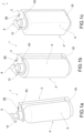
Figures 1a, 1b and 1c depict some embodiments of a dispensing unit according to the present invention; -
Figure 1d represents a bottom of a bottle of a dispenser of the dispensing unit according to the present invention; -
Figure 1e illustrates a dispensing unit according to an embodiment of the present invention, wherein the bottle is provided with a label; -
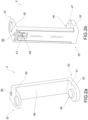
Figures 2a and 2b illustrate a support device for the dispensing unit according to the present invention; -
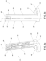
Figures 3a and 3b show a mounting body for the support device ofFigures 2a and 2b ; -
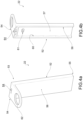
Figures 4a and 4b illustrate a covering body of the support device ofFigures 2a and 2b ; -
Figure 5a illustrates the dispensing unit according to the present invention, in accordance with a further embodiment; -
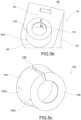
Figure 5b illustrates an assembly consisting of a support device for the dispensing unit ofFigure 5a and a security collar; -
Figure 5c represents the security collar ofFigure 5b ; -
Figure 6a illustrates the dispensing unit according to the present invention, in accordance with a further embodiment; -
Figure 6b illustrates a support device for the dispensing unit ofFigure 6a ; -
Figure 6c represents a security collar of the dispensing unit ofFigure 6a ; -
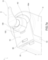
Figure 7a illustrates the dispensing unit according to the present invention, in accordance with a further embodiment; -
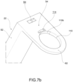
Figure 7b illustrates a support device for the dispensing unit ofFigure 7a ; -
Figures 7c and 7d represent a security collar of the dispensing unit ofFigure 7a . - With reference to the accompanying figures, a dispensing unit is indicated collectively at 1 comprising a
support device 2 suitable to be mounted to the wall, for example by screws or with double-sided adhesive tape, and adispenser 4', 4", 4‴ supported by thesupport device 2 and separable therefrom. - The dispenser 4', 4'', 4‴ comprises a
bottle 6, e.g. circular or quadrangular in shape, and a dispensinghead 8 applied to thebottle 6 in an engagement region, e.g. by threaded or bayonet attachment. - The dispensing
head 8 is manually operable for dispensing the product contained in the bottle. - For example, the dispensing
head 8 comprises anozzle 10 which, manually lowered from an initial rest position, causes the product to be dispensed, and when released returns to the rest position. - The
bottle 6 has abottom 7a and aside wall 7b. In thebottom 7a acavity 9 is obtained, which will be discussed hereinafter. - According to an embodiment, moreover, the
bottle 6 comprises alabel 11 applied to only one region of theside wall 7b; in other words, a further region of theside wall 7b, and in particular the one facing the wall to which the dispensing unit is mounted, does not have a label, so as to allow staff to verify the level of product contained, while this level is essentially hidden from the normal user. - In normal use of the dispensing unit, however, the
label 11 is visible, so that the user may be informed about the contents of the bottle and the composition of the dispensable product. Furthermore, the entire bottle is visible, so as to be able to present various designs. - The
support device 2 comprises amounting body 20 and a coveringbody 22. - The mounting body 20 (
Figures 3a and 3b ) is substantially L-shaped and comprises amounting plate 24, intended to be mounted to the wall, having a predominant extension along a vertical direction Y between anupper end 26 and alower end 28, and afoot 30, protruding from themounting plate 24 at thelower end 28 thereof. - Preferably, the
mounting body 20 is made as a single piece out of plastic material, obtained by injection molding. - The
mounting plate 24 haslateral sides mounting body 20 with the coveringbody 22. - The
support device 2 further comprises hooking means suitable for a snap-engagement of themounting body 20 with the coveringbody 22. - For example, said hooking means comprise a pair of
flexible prongs mounting plate 24; saidprongs fork 46. - The
foot 30 has a substantially flatupper surface 46, and anengagement projection 48, protruding from theupper surface 47, intended for shape-coupling with thecavity 9 of thebottom 7a of thebottle 6. - According to a preferred embodiment, the
engagement projection 48 is circular cylindrical in shape; according to other embodiments, the engagement projection is frustoconical or prismatic in shape, and thus also is thecavity 9. In any case, thecavity 9 of thebottom 7a of thebottle 6 and theengagement projection 48 of thefoot 30 of themounting body 20 form a shape-coupling so that theengagement projection 48 is insertable in thecavity 9. - The frustoconical shape is particularly advantageous, as it allows the bottle to be kept in the correct position during normal use by virtue of the friction between the surface of the cavity and that of the projection, and, at the same time, to be able to rotate the bottle to view the level of the remaining product.
- The covering body 22 (
Figures 4a and 4b ) is essentially L-shaped and comprises a coveringportion 52 and agripping portion 54. - The covering
portion 52, which extends between anupper end 53 and alower end 55, has a substantiallyflat front surface 56, configured to cover themounting plate 24 when the coveringbody 22 is applied to themounting body 20, and aback surface 57. - At the back, moreover, the
covering portion 52 comprises a pair ofside guides side panels mounting plate 24. - Moreover, the covering
portion 52 comprises a hookingelement 61, protruding from therear surface 57, to form a snap-engagement with thefork 46 of the mounting plate. - In other words, the hooking means comprise said hooking
element 61. - The gripping
portion 54 protrudes from the coveringportion 52 at thetop end 53. - Said gripping
portion 54 comprises agripping collar 62, which delimits a gripping opening 62a suitable for inserting thebottle 6 near the neck thereof or near the dispensinghead 8. - Said gripping
portion 54 also moreover has akey opening 64 which makes the rear part of the covering portion accessible from above. - In particular, said
key opening 64 makes it possible to insert a security key suitable to deactivate the hooking means, i.e. suitable to disengage thefork 46 from thehooking element 61. - For the wall installation of the
support device 2, themounting plate 24 of themounting body 20 is applied to the wall, typically by means of screws or anchors. - When the dispenser 4', 4'', 4''' is arranged, moreover, the
nozzle 10 is passed through thegripping collar 62 of the coveringbody 22. - The covering
body 22 is then slidable coupled with the mounting body 20 (in particular, thelateral guides body 22 slide along thelateral sides mounting body 20, until reaching an engagement configuration (Figures 2a and 2b ) wherein thefork 46 is snap-engaged with the hooking element 61) and at the same time thebottom 7a of thebottle 6 is inserted on theengagement projection 48 of thefoot 30 of themounting body 20, so as to be accommodated in thecavity 9 of thebottom 7a of thebottle 6. - In other words, the
bottle 6 is insertable vertically on thefoot 30 of themounting body 20, so that theengagement projection 48 is inserted vertically into thecavity 9 of thebottom 7a of thebottle 6. - According to a further embodiment of the invention (
Figures 5a to 5c ), the dispensing unit 1 comprises asecurity collar 100 applicable to the grippingcollar 62 so as to cover at least partially the engagement region of the dispensinghead 8 with thebottle 2. - Preferably, the
security collar 100 is cup-shaped and comprises acylindrical collar wall 102, acollar edge 104 protruding radially externally from alower end 102a of thecollar wall 102, and acollar crown 106 protruding radially internally from anupper end 102b of thecollar wall 102. - The
security collar 100 has alongitudinal split 108 which, in a predefined angular position, interrupts the annular continuity of thecollar edge 104, thecollar wall 102 and thecollar crown 106. - The gripping
opening 62a has, in a predefined angular position, aprojection 110 suitable to couple with thesplit 108 of thesecurity collar 100 so as to block the rotation of thesecurity collar 100 inserted in the gripping opening 62a. - For the assembly of the dispensing unit, the
security collar 100 is applied to thegripping collar 62 of the coveringbody 22; then the dispensinghead 8 is inserted through thesecurity collar 100, so that the engagement region is at least partially covered by thesecurity collar 100; finally, thebottle 6 is positioned so that theengagement projection 48 is inserted in thecavity 9 and the covering body is coupled to themounting body 20. - The
security collar 100 is bound axially to the grippingcollar 62 by virtue of thecollar edge 104 and rotationally by virtue of thegripping projection 110 inserted in thesplit 108; the engagement area wherein the dispensing head is screwed or otherwise engaged with the bottle is therefore not accessible to a user. - According to a further embodiment (
Figures 6a to 6c ), thegripping projection 110 has a greater angular extension than in the embodiment mentioned with reference toFigures 5a to 5c , and correspondingly thesplit 108 of thesecurity collar 100 is larger. - Preferably, moreover, the
security collar 100 has asecurity projection 112 protruding from anupper surface 104a of thesecurity edge 104; correspondingly, the grippingcollar 62 has agripping seat 114 obtained on alower surface 62b of thegripping collar 62. Thegripping seat 114 is suitable to accommodate thesecurity projection 112. - According to a still further embodiment (
Figures 7a to 7d ), thesecurity collar 100 has limited angular extension, and thesecurity wall 102, thesecurity edge 104 and thesecurity crown 106 consist of cylindrical sectors. - Moreover, the
security projection 112 has greater angular extension than in the embodiment shown inFigures 6a to 6c and thegripping seat 114 passes through the thickness of thegripping collar 62. - Moreover, the gripping
projection 110 extends over most of the angular extension of thegripping opening 62a, so that thesecurity wall 102 may be inserted into the remainingspace 110b. - In this embodiment, the engagement region between the dispensing
head 8 and thebottle 6 may be reached by a user, but in any case, the dispensinghead 8 is not separable from thebottle 6 by virtue of the retention enacted by thesecurity crown 106. - Innovatively, the dispensing unit 1 according to the present invention meets the needs of the sector and overcomes the drawbacks mentioned with reference to the prior art because the dispenser may no longer be unscrewed and unlawfully removed, as it is blocked at the top by the collar and below by the coupling with the engagement projection.
- Moreover, the bottle is exposed as well as the label, so that the user may be informed about the nature of the product to be dispensed and the composition. In other words, between the
foot 30 and thegripping collar 62 a compartment is defined for the reception of the bottle and the compartment is free of panels, so as to leave the bottle exposed. - Advantageously, moreover, by properly configuring the engagement projection and the cavity, a univocal match is created between the dispenser and the support device, so that each dispenser may be coupled to a respective support device, in such a way that the service personnel may distribute the various products without making mistakes.
- Another advantage of the dispensing unit according to the present invention is that it allows one to limit the use of counterfeit dispensers and products which are at times dangerous, because only dispensers containing original products have a cavity corresponding to a predefined engagement projection.
- Advantageously, moreover, by modifying the aesthetics of the dispenser bottle alone, the aesthetics of the entire dispensing unit are modified. This is particularly appreciated, for example, by hoteliers, who may introduce new elements into the aesthetics of a room by changing the aesthetics of the bottle alone.
- Furthermore, the support device may be mounted to the wall by means of screws or anchors or by means of double-sided adhesive tape; advantageously, this allows an application to the wall according to various needs.
- According to an even more advantageous aspect, the dispensing unit provides that the dispensing head is separable from the bottle only by the staff in charge of the arrangement of the hotel rooms, equipped with the release key, while it is not separable by the users.
- It is clear that one skilled in the art, in order to meet contingent needs, may make changes to the dispensing unit described above, all contained within the scope of protection as defined by the following claims.
Claims (9)
- Device (2) mountable to the wall to support a dispenser (4',4",4‴) consisting of a bottle (6) and a dispensing head (8) coupled in an engagement region, comprising:- a mounting body (20) having a mounting plate (24), intended to be mounted to the wall, and a foot (30), projecting from the mounting plate (24), wherein the foot (30) has an upper surface (47) and an engagement projection (48) protruding from the upper surface (47);- a covering body (22) comprising a cover (52), configured to cover at least partially the mounting plate (24), and a gripping portion (54), projecting from the cover (52) and comprising a gripping collar (62) engageable with the dispenser, wherein the covering body (22) may be slidably coupled with the mounting body (20), wherein between the foot (30) and the gripping collar (62) a compartment is defined for accommodating the bottle;- security means (42,44;56;61;64) adapted to obtain a snap engagement between the covering body (22) and the mounting body (20), said security means being releasable and comprising an opening (64) obtained through the covering body (22), adapted to insert a key for releasing the security means;- wherein the engagement projection (48) has a predefined configuration for univocally coupling with a bottom (7a) of the bottle (6) of the dispenser (4', 4", 4‴);- wherein said compartment of the device is free of panels, so as to leave the bottle visible.
- Device according to claim 1, wherein said security means comprise a flexible fork (46) of the mounting plate (24) and a hooking element (61) of the cover (52).
- Device according to claim 1 or 2, wherein the mounting plate (24) comprises a pair of lateral sides (32,34) and the cover (52) comprises a pair of lateral guides (32,34) each having an undercut (36), wherein said lateral guides may be slidably coupled with the lateral sides, until they reach a configuration of engagement wherein said security means are active.
- Device according to any one of the preceding claims, comprising a security collar (100) applicable to the gripping collar (62) so as to be bound axially thereto, said security collar (100) being provided with a security crown (106) suitable to cover at least partially the engagement region between the dispensing head (8) and the bottle (6) to prevent the separation of the dispensing head (8) from the bottle (6).
- Device according to any one of the preceding claims, comprising a security collar (100) applicable to the gripping collar (62), said security collar (100) being equipped with a security wall (102) suitable to cover at least partially the engagement region between the dispensing head (8) and the bottle (6) to prevent the access to said engagement region by a user.
- Device (2) according to any one of the preceding claims, wherein the engagement projection (48) is circular cylindrical in shape.
- Device (2) according to claim 2, wherein the hooking element (61) protrudes from the rear surface (57) and is suitable to form a snap-engagement with the fork (46) of the mounting plate.
- Device according to any one of the preceding claims, wherein the security collar (100) has limited angular extension, and the security wall (102), the security edge (104) and the security crown (106) consist of cylindrical sectors.
- Dispensing unit (1) comprising:- a device (2) according to any one of claims 1 to 8; and- a dispenser (4', 4", 4‴) comprising:-- a bottle (6) comprising a bottom (7a) provided with a cavity (9) for the univocal coupling with a support device (2) of the dispenser (4', 4", 4‴), wherein said cavity has a frustoconical shape, made at the center of the bottom of the bottle; and-- a dispensing head (8) applied to the bottle (6) and manually operable for dispensing a product contained in the bottle.
Priority Applications (1)
| Application Number | Priority Date | Filing Date | Title |
|---|---|---|---|
| HRP20250905TT HRP20250905T1 (en) | 2018-11-29 | 2019-11-27 | DOSING UNIT |
Applications Claiming Priority (2)
| Application Number | Priority Date | Filing Date | Title |
|---|---|---|---|
| IT102018000010692A IT201800010692A1 (en) | 2018-11-29 | 2018-11-29 | DISPENSING GROUP |
| PCT/IB2019/060234 WO2020110033A2 (en) | 2018-11-29 | 2019-11-27 | Dispensing unit |
Publications (3)
| Publication Number | Publication Date |
|---|---|
| EP3886665A2 EP3886665A2 (en) | 2021-10-06 |
| EP3886665C0 EP3886665C0 (en) | 2025-07-02 |
| EP3886665B1 true EP3886665B1 (en) | 2025-07-02 |
Family
ID=65685878
Family Applications (1)
| Application Number | Title | Priority Date | Filing Date |
|---|---|---|---|
| EP19817414.6A Active EP3886665B1 (en) | 2018-11-29 | 2019-11-27 | Dispensing unit |
Country Status (8)
| Country | Link |
|---|---|
| US (1) | US12070167B2 (en) |
| EP (1) | EP3886665B1 (en) |
| CN (1) | CN113226137B (en) |
| ES (1) | ES3046557T3 (en) |
| HR (1) | HRP20250905T1 (en) |
| IT (1) | IT201800010692A1 (en) |
| PL (1) | PL3886665T3 (en) |
| WO (1) | WO2020110033A2 (en) |
Families Citing this family (19)
| Publication number | Priority date | Publication date | Assignee | Title |
|---|---|---|---|---|
| FR3111126B1 (en) * | 2020-06-09 | 2022-07-01 | M G L F | Assembly comprising a liquid dispenser and a support element |
| US11857126B2 (en) * | 2020-12-01 | 2024-01-02 | Cintas Corporate Services, Inc. | Theft deterrent dispenser and mounting assembly |
| US20240188763A1 (en) * | 2021-04-21 | 2024-06-13 | ADA Cosmetics International GmbH | Wall-mounted dispenser |
| DE102021126809A1 (en) * | 2021-10-15 | 2022-09-29 | ADA Cosmetics International GmbH | wall dispenser |
| US12185884B2 (en) * | 2021-10-07 | 2025-01-07 | Deb Ip Limited | Dispenser |
| USD1037703S1 (en) * | 2021-11-08 | 2024-08-06 | Anuradha Andy De Silva | Wall-mounted soap dispenser |
| DE202022101086U1 (en) | 2022-02-25 | 2022-03-04 | Thomas Kriz | extraction device |
| US12232666B2 (en) * | 2022-06-09 | 2025-02-25 | Salto, Llc | Adjustable holder for a fluid dispensing container |
| USD1049694S1 (en) * | 2022-07-28 | 2024-11-05 | Wenesy Cosmetics Ltd. | Soap dispenser |
| USD1138320S1 (en) * | 2022-10-11 | 2026-08-04 | Linlin Li | Wall mounted soap dispenser |
| USD1011078S1 (en) * | 2022-11-14 | 2024-01-16 | Gfl Sa | Liquid soap dispenser holder |
| USD1086740S1 (en) * | 2023-03-17 | 2025-08-05 | Soft Touch Corp. | Soap dispenser |
| US20240418012A1 (en) * | 2023-06-13 | 2024-12-19 | We Can Do That Incorporated Dba Aquamenities | Securing a toiletries dispensing device |
| US12540015B2 (en) | 2023-09-11 | 2026-02-03 | Hotel Emporium Inc. | Liquid product dispenser with tamper resistant overcap |
| USD1068491S1 (en) * | 2023-10-27 | 2025-04-01 | Jiangsu Hanhe Daily Necessities Co., Ltd. | Bottle |
| CN117378951A (en) * | 2023-11-14 | 2024-01-12 | 江苏欧佩日化股份有限公司 | Soap dispenser |
| USD1124706S1 (en) * | 2023-11-14 | 2026-05-05 | Jiangsu Oppeal Daily Cosmetics Corp., Ltd. | Wall mounted soap dispenser |
| USD1114521S1 (en) * | 2024-03-12 | 2026-02-24 | Marietta Corporation | Liquid dispenser |
| US12458162B1 (en) * | 2024-06-19 | 2025-11-04 | John M. Tursky | Utility holder |
Citations (2)
| Publication number | Priority date | Publication date | Assignee | Title |
|---|---|---|---|---|
| US5971335A (en) * | 1996-07-03 | 1999-10-26 | Perrin Manufacturing Company | Holder for dispensing containers |
| US20050017146A1 (en) * | 2003-07-25 | 2005-01-27 | Kringel George N. | Product display device |
Family Cites Families (36)
| Publication number | Priority date | Publication date | Assignee | Title |
|---|---|---|---|---|
| US3032081A (en) * | 1959-09-24 | 1962-05-01 | Cotta Andrew J La | Dispensing apparatus |
| US4582227A (en) * | 1983-08-01 | 1986-04-15 | Go-Jo Industries, Inc. | Pump dispenser assembly |
| US4651902A (en) * | 1984-06-04 | 1987-03-24 | Huntington Laboratories, Inc. | Fluid-dispensing apparatus |
| US4874113A (en) * | 1988-02-22 | 1989-10-17 | Schmidt Laurie H | Dispensers for cosmetics |
| US5277332A (en) * | 1993-02-04 | 1994-01-11 | Isabel Rogers | Multiple dispensing container for viscous materials, cups and toothpaste |
| US5435511A (en) * | 1994-01-26 | 1995-07-25 | Hsu; Hsiang-Yuan | Modular fastener assembly for fastening an aquatic appliance to an aquatic tank |
| DE19536739A1 (en) * | 1995-10-02 | 1997-04-03 | Zeller Engineering Gmbh | Dosing dispenser for liquids |
| US6041974A (en) * | 1998-10-30 | 2000-03-28 | Highland Laboratories, Inc. | Wall mounted fluid dispenser |
| US6637707B1 (en) * | 1999-12-13 | 2003-10-28 | All Rite Products, Inc. | Removable holder |
| US6318600B1 (en) * | 2000-02-02 | 2001-11-20 | Harold G. Winnett | Dispenser for dispensing shaving cream or other aerosol dispensed products from cans having different heights and diameters |
| US6910604B2 (en) | 2002-01-17 | 2005-06-28 | Carmine Gugliotti | Kitchen sink top-mounted rigid stem-portable dispenser soap system |
| US6820770B2 (en) | 2002-12-06 | 2004-11-23 | The Dial Corporation | Dispenser holder for vehicles |
| US7654417B2 (en) * | 2004-06-28 | 2010-02-02 | Aluta, Inc. | Refillable product dispenser and system |
| CA2496412C (en) * | 2005-02-09 | 2013-06-18 | Hygiene-Technik Inc. | Fluid dispenser lock defeater |
| DE102006043309A1 (en) * | 2006-09-08 | 2008-03-27 | Adolf Würth GmbH & Co. KG | liquid dispenser |
| FR2931052B1 (en) * | 2008-05-13 | 2012-08-03 | Occitane L | LIQUID DISPENSER WITH DISSIMULATED REFILL |
| DE102009049261B4 (en) * | 2009-10-13 | 2014-10-09 | Csd Gmbh Cosmetic Systems Development & Distribution | Wanddosierspender |
| DE202010009176U1 (en) * | 2010-06-17 | 2011-12-19 | Ada Cosmetic Gmbh | Wanddosierspender |
| US20120181405A1 (en) * | 2011-01-14 | 2012-07-19 | Doug Zlatic | Bottle mounting system including separable bottle and clamp |
| US20130098941A1 (en) * | 2011-10-25 | 2013-04-25 | Gojo Industries, Inc. | Proprietary dispensing container system |
| US9265384B2 (en) * | 2013-01-16 | 2016-02-23 | Gojo Industries, Inc. | Point-of-care compliance module |
| US9027797B2 (en) | 2013-01-23 | 2015-05-12 | Gojo Industries, Inc. | Shield for a fluid dispenser |
| CN203987793U (en) * | 2014-01-09 | 2014-12-10 | 广东省外贸开发公司 | Combined type lotion pump |
| US20150235549A1 (en) * | 2014-02-20 | 2015-08-20 | Debmed Usa Llc | Electronically monitored and portable point-of-care hand hygiene dispenser having security features |
| WO2016161318A1 (en) * | 2015-04-01 | 2016-10-06 | Ecolab Usa Inc. | Flexible mounting system for hand hygiene dispensers |
| CN204931520U (en) * | 2015-09-01 | 2016-01-06 | 上海利康智慧医疗科技有限公司 | Liquid getting device |
| WO2018038686A1 (en) * | 2016-08-23 | 2018-03-01 | Karaman Nurettin | Foam dispenser |
| DE102016119609A1 (en) * | 2016-10-14 | 2018-04-19 | Bode Chemie Gmbh | Container receiving device for a dispensing container |
| GB2559103A (en) * | 2016-10-14 | 2018-08-01 | Bradley Mark | Dispensing system |
| US10342391B2 (en) | 2016-12-01 | 2019-07-09 | Colgate-Palmolive Company | Bottle holder |
| CN108497975A (en) * | 2017-02-28 | 2018-09-07 | 上海利康消毒高科技有限公司 | A kind of liquid distributor fixing device |
| DE202018106397U1 (en) * | 2018-11-12 | 2019-01-29 | Icon Guest Concepts & Supply Gmbh | Device for dispensing a liquid product |
| USD905466S1 (en) * | 2018-11-29 | 2020-12-22 | Gfl S.A. | Liquid soap dispenser |
| USD918017S1 (en) * | 2019-01-22 | 2021-05-04 | Sysco Guest Supply, Llc | Wall-mounted bracket |
| USD1002387S1 (en) * | 2019-10-03 | 2023-10-24 | Marietta Corporation | Bottle and a mount assembly |
| US11857126B2 (en) * | 2020-12-01 | 2024-01-02 | Cintas Corporate Services, Inc. | Theft deterrent dispenser and mounting assembly |
-
2018
- 2018-11-29 IT IT102018000010692A patent/IT201800010692A1/en unknown
-
2019
- 2019-11-27 EP EP19817414.6A patent/EP3886665B1/en active Active
- 2019-11-27 PL PL19817414.6T patent/PL3886665T3/en unknown
- 2019-11-27 ES ES19817414T patent/ES3046557T3/en active Active
- 2019-11-27 US US17/297,646 patent/US12070167B2/en active Active
- 2019-11-27 WO PCT/IB2019/060234 patent/WO2020110033A2/en not_active Ceased
- 2019-11-27 CN CN201980079325.4A patent/CN113226137B/en active Active
- 2019-11-27 HR HRP20250905TT patent/HRP20250905T1/en unknown
Patent Citations (2)
| Publication number | Priority date | Publication date | Assignee | Title |
|---|---|---|---|---|
| US5971335A (en) * | 1996-07-03 | 1999-10-26 | Perrin Manufacturing Company | Holder for dispensing containers |
| US20050017146A1 (en) * | 2003-07-25 | 2005-01-27 | Kringel George N. | Product display device |
Also Published As
| Publication number | Publication date |
|---|---|
| CN113226137A (en) | 2021-08-06 |
| IT201800010692A1 (en) | 2020-05-29 |
| US12070167B2 (en) | 2024-08-27 |
| WO2020110033A3 (en) | 2020-07-30 |
| EP3886665A2 (en) | 2021-10-06 |
| US20220007897A1 (en) | 2022-01-13 |
| ES3046557T3 (en) | 2025-12-02 |
| HRP20250905T1 (en) | 2025-09-26 |
| WO2020110033A2 (en) | 2020-06-04 |
| PL3886665T3 (en) | 2025-09-08 |
| EP3886665C0 (en) | 2025-07-02 |
| CN113226137B (en) | 2022-12-06 |
Similar Documents
| Publication | Publication Date | Title |
|---|---|---|
| US12070167B2 (en) | Dispensing unit | |
| US8485395B2 (en) | Dispenser lockout mechanism | |
| US20240188763A1 (en) | Wall-mounted dispenser | |
| US20080023490A1 (en) | Secure surface mounted dispensing system | |
| CA2816858C (en) | Dispenser with flexible cover | |
| EP2698340B1 (en) | Material dispenser adapted for use with various sizes of cartridges | |
| EP3795043B1 (en) | Soap dispenser for use in shower room in hotel bathroom | |
| US11027305B2 (en) | Accommodating means for a dispensing container | |
| CN115973588B (en) | Wall mounted metering dispenser | |
| US7044328B1 (en) | Tamper proof latch for dispensers | |
| US20050184097A1 (en) | Surface mounted dispensing system | |
| CN121152589A (en) | Installable and supplementable distribution system | |
| US8020731B2 (en) | Dispenser | |
| EP2683282B1 (en) | Dispenser with suction cups | |
| US20190315516A1 (en) | Dispenser with surface mounted holding system | |
| US8870031B2 (en) | Dispenser | |
| US20190261816A1 (en) | Wall-mounted holder assembly for liquid/gel dispenser | |
| CN117157000A (en) | wall mounted dispenser | |
| US20050077422A1 (en) | Roll dispenser | |
| HK40083897A (en) | Wall-mounted metering dispenser | |
| IT202000004528U1 (en) | DEVICE FOR DISPENSING A PRODUCT IN THE FORM OF A LIQUID FLUID |
Legal Events
| Date | Code | Title | Description |
|---|---|---|---|
| REG | Reference to a national code |
Ref country code: HR Ref legal event code: TUEP Ref document number: P20250905T Country of ref document: HR |
|
| STAA | Information on the status of an ep patent application or granted ep patent |
Free format text: STATUS: UNKNOWN |
|
| STAA | Information on the status of an ep patent application or granted ep patent |
Free format text: STATUS: THE INTERNATIONAL PUBLICATION HAS BEEN MADE |
|
| PUAI | Public reference made under article 153(3) epc to a published international application that has entered the european phase |
Free format text: ORIGINAL CODE: 0009012 |
|
| STAA | Information on the status of an ep patent application or granted ep patent |
Free format text: STATUS: REQUEST FOR EXAMINATION WAS MADE |
|
| 17P | Request for examination filed |
Effective date: 20210526 |
|
| AK | Designated contracting states |
Kind code of ref document: A2 Designated state(s): AL AT BE BG CH CY CZ DE DK EE ES FI FR GB GR HR HU IE IS IT LI LT LU LV MC MK MT NL NO PL PT RO RS SE SI SK SM TR |
|
| DAV | Request for validation of the european patent (deleted) | ||
| DAX | Request for extension of the european patent (deleted) | ||
| STAA | Information on the status of an ep patent application or granted ep patent |
Free format text: STATUS: EXAMINATION IS IN PROGRESS |
|
| 17Q | First examination report despatched |
Effective date: 20240103 |
|
| TPAC | Observations filed by third parties |
Free format text: ORIGINAL CODE: EPIDOSNTIPA |
|
| GRAP | Despatch of communication of intention to grant a patent |
Free format text: ORIGINAL CODE: EPIDOSNIGR1 |
|
| STAA | Information on the status of an ep patent application or granted ep patent |
Free format text: STATUS: GRANT OF PATENT IS INTENDED |
|
| INTG | Intention to grant announced |
Effective date: 20250212 |
|
| GRAS | Grant fee paid |
Free format text: ORIGINAL CODE: EPIDOSNIGR3 |
|
| GRAA | (expected) grant |
Free format text: ORIGINAL CODE: 0009210 |
|
| STAA | Information on the status of an ep patent application or granted ep patent |
Free format text: STATUS: THE PATENT HAS BEEN GRANTED |
|
| AK | Designated contracting states |
Kind code of ref document: B1 Designated state(s): AL AT BE BG CH CY CZ DE DK EE ES FI FR GB GR HR HU IE IS IT LI LT LU LV MC MK MT NL NO PL PT RO RS SE SI SK SM TR |
|
| REG | Reference to a national code |
Ref country code: GB Ref legal event code: FG4D |
|
| REG | Reference to a national code |
Ref country code: CH Ref legal event code: EP |
|
| REG | Reference to a national code |
Ref country code: DE Ref legal event code: R096 Ref document number: 602019072027 Country of ref document: DE |
|
| REG | Reference to a national code |
Ref country code: IE Ref legal event code: FG4D |
|
| U01 | Request for unitary effect filed |
Effective date: 20250702 |
|
| U07 | Unitary effect registered |
Designated state(s): AT BE BG DE DK EE FI FR IT LT LU LV MT NL PT RO SE SI Effective date: 20250710 |
|
| REG | Reference to a national code |
Ref country code: HR Ref legal event code: T1PR Ref document number: P20250905 Country of ref document: HR |
|
| U20 | Renewal fee for the european patent with unitary effect paid |
Year of fee payment: 7 Effective date: 20251020 |
|
| REG | Reference to a national code |
Ref country code: ES Ref legal event code: FG2A Ref document number: 3046557 Country of ref document: ES Kind code of ref document: T3 Effective date: 20251202 |
|
| REG | Reference to a national code |
Ref country code: HR Ref legal event code: ODRP Ref document number: P20250905 Country of ref document: HR Payment date: 20251003 Year of fee payment: 7 |
|
| PG25 | Lapsed in a contracting state [announced via postgrant information from national office to epo] |
Ref country code: IS Free format text: LAPSE BECAUSE OF FAILURE TO SUBMIT A TRANSLATION OF THE DESCRIPTION OR TO PAY THE FEE WITHIN THE PRESCRIBED TIME-LIMIT Effective date: 20251102 |
|
| PGFP | Annual fee paid to national office [announced via postgrant information from national office to epo] |
Ref country code: GB Payment date: 20251121 Year of fee payment: 7 |
|
| PG25 | Lapsed in a contracting state [announced via postgrant information from national office to epo] |
Ref country code: NO Free format text: LAPSE BECAUSE OF FAILURE TO SUBMIT A TRANSLATION OF THE DESCRIPTION OR TO PAY THE FEE WITHIN THE PRESCRIBED TIME-LIMIT Effective date: 20251002 |
|
| PGFP | Annual fee paid to national office [announced via postgrant information from national office to epo] |
Ref country code: HR Payment date: 20251003 Year of fee payment: 7 |
|
| PG25 | Lapsed in a contracting state [announced via postgrant information from national office to epo] |
Ref country code: GR Free format text: LAPSE BECAUSE OF FAILURE TO SUBMIT A TRANSLATION OF THE DESCRIPTION OR TO PAY THE FEE WITHIN THE PRESCRIBED TIME-LIMIT Effective date: 20251003 |
|
| PGFP | Annual fee paid to national office [announced via postgrant information from national office to epo] |
Ref country code: TR Payment date: 20251103 Year of fee payment: 7 |
|
| PG25 | Lapsed in a contracting state [announced via postgrant information from national office to epo] |
Ref country code: CZ Free format text: LAPSE BECAUSE OF FAILURE TO SUBMIT A TRANSLATION OF THE DESCRIPTION OR TO PAY THE FEE WITHIN THE PRESCRIBED TIME-LIMIT Effective date: 20250702 |
|
| PGFP | Annual fee paid to national office [announced via postgrant information from national office to epo] |
Ref country code: IE Payment date: 20251121 Year of fee payment: 7 |
|
| PGFP | Annual fee paid to national office [announced via postgrant information from national office to epo] |
Ref country code: PL Payment date: 20251113 Year of fee payment: 7 |
|
| PG25 | Lapsed in a contracting state [announced via postgrant information from national office to epo] |
Ref country code: RS Free format text: LAPSE BECAUSE OF FAILURE TO SUBMIT A TRANSLATION OF THE DESCRIPTION OR TO PAY THE FEE WITHIN THE PRESCRIBED TIME-LIMIT Effective date: 20251002 |
|
| PGFP | Annual fee paid to national office [announced via postgrant information from national office to epo] |
Ref country code: ES Payment date: 20251201 Year of fee payment: 7 |
|
| PG25 | Lapsed in a contracting state [announced via postgrant information from national office to epo] |
Ref country code: SM Free format text: LAPSE BECAUSE OF FAILURE TO SUBMIT A TRANSLATION OF THE DESCRIPTION OR TO PAY THE FEE WITHIN THE PRESCRIBED TIME-LIMIT Effective date: 20250702 |
|
| PG25 | Lapsed in a contracting state [announced via postgrant information from national office to epo] |
Ref country code: SK Free format text: LAPSE BECAUSE OF FAILURE TO SUBMIT A TRANSLATION OF THE DESCRIPTION OR TO PAY THE FEE WITHIN THE PRESCRIBED TIME-LIMIT Effective date: 20250702 |
|
| PLBE | No opposition filed within time limit |
Free format text: ORIGINAL CODE: 0009261 |
|
| STAA | Information on the status of an ep patent application or granted ep patent |
Free format text: STATUS: NO OPPOSITION FILED WITHIN TIME LIMIT |
|
| REG | Reference to a national code |
Ref country code: CH Ref legal event code: L10 Free format text: ST27 STATUS EVENT CODE: U-0-0-L10-L00 (AS PROVIDED BY THE NATIONAL OFFICE) Effective date: 20260518 |
|
| 26N | No opposition filed |
Effective date: 20260407 |
|
| REG | Reference to a national code |
Ref country code: CH Ref legal event code: H13 Free format text: ST27 STATUS EVENT CODE: U-0-0-H10-H13 (AS PROVIDED BY THE NATIONAL OFFICE) Effective date: 20260623 |
|
| PG25 | Lapsed in a contracting state [announced via postgrant information from national office to epo] |
Ref country code: MC Free format text: LAPSE BECAUSE OF FAILURE TO SUBMIT A TRANSLATION OF THE DESCRIPTION OR TO PAY THE FEE WITHIN THE PRESCRIBED TIME-LIMIT Effective date: 20250702 |
|
| PG25 | Lapsed in a contracting state [announced via postgrant information from national office to epo] |
Ref country code: CH Free format text: LAPSE BECAUSE OF NON-PAYMENT OF DUE FEES Effective date: 20251130 |