EP3886465A1 - Sound signal output method, sound signal output device and program - Google Patents
Sound signal output method, sound signal output device and program Download PDFInfo
- Publication number
- EP3886465A1 EP3886465A1 EP21160960.7A EP21160960A EP3886465A1 EP 3886465 A1 EP3886465 A1 EP 3886465A1 EP 21160960 A EP21160960 A EP 21160960A EP 3886465 A1 EP3886465 A1 EP 3886465A1
- Authority
- EP
- European Patent Office
- Prior art keywords
- sound signal
- sound
- reproduction information
- signal output
- areas
- Prior art date
- Legal status (The legal status is an assumption and is not a legal conclusion. Google has not performed a legal analysis and makes no representation as to the accuracy of the status listed.)
- Pending
Links
Images






Classifications
-
- H—ELECTRICITY
- H04—ELECTRIC COMMUNICATION TECHNIQUE
- H04S—STEREOPHONIC SYSTEMS
- H04S7/00—Indicating arrangements; Control arrangements, e.g. balance control
- H04S7/30—Control circuits for electronic adaptation of the sound field
- H04S7/302—Electronic adaptation of stereophonic sound system to listener position or orientation
-
- H—ELECTRICITY
- H04—ELECTRIC COMMUNICATION TECHNIQUE
- H04R—LOUDSPEAKERS, MICROPHONES, GRAMOPHONE PICK-UPS OR LIKE ACOUSTIC ELECTROMECHANICAL TRANSDUCERS; ELECTRIC HEARING AIDS; PUBLIC ADDRESS SYSTEMS
- H04R3/00—Circuits for transducers
- H04R3/12—Circuits for transducers for distributing signals to two or more loudspeakers
-
- H—ELECTRICITY
- H04—ELECTRIC COMMUNICATION TECHNIQUE
- H04R—LOUDSPEAKERS, MICROPHONES, GRAMOPHONE PICK-UPS OR LIKE ACOUSTIC ELECTROMECHANICAL TRANSDUCERS; ELECTRIC HEARING AIDS; PUBLIC ADDRESS SYSTEMS
- H04R27/00—Public address systems
Definitions
- One embodiment of the present application relates to a sound signal output method, a sound signal output device and a program executable by the sound signal output device to perform the sound signal output method.
- Unexamined Japanese Patent Publication No. 2017-41897 discloses a device capable of specifying a localization position of a sound source at any optional position within an area to which a sound signal is outputted.
- the device disclosed in Unexamined Japanese Patent Publication No. 2017-41897 does not consider the case where a plurality of areas to which a sound signal is outputted are provided. For instance, a user may desire to output each of sound signals of different sound sources to the corresponding one of a first area and a second area.
- An object of one embodiment of the present application is to provide a sound signal output method and a sound signal output device capable of outputting a sound signal of any optional sound source to each of a plurality of areas.
- the sound signal output method of outputting sound to a plurality of areas obtains a sound signal of a sound source, receives a setting of reproduction information indicating whether or not to output the sound signal of the above-mentioned sound source to each of the plurality of areas where the above-mentioned sound signal is to be output, and outputs the above-mentioned reproduction information and the above-mentioned sound signal, or reproduces the above-mentioned sound signal based on the above-mentioned reproduction information.
- a sound signal of any optional sound source can be outputted to each of a plurality of areas.
- FIG. 1 is a block diagram showing a configuration of a sound signal output device 1.
- the sound signal output device 1 includes a communicator 11, a processor 12, a RAM 13, a flash memory 14, a display 15, a user I/F 16, and an audio I/F 17.
- the sound signal output device 1 is constituted by a personal computer, a smart phone, a tablet computer, or the like. Further, audio equipment such as an audio mixer is also an example of the sound signal output device.
- the communicator 11 communicates with other devices such as a server.
- the communicator 11 receives a sound signal of a sound source, for example.
- the processor 12 is constituted by a CPU, a DSP, an SoC (System on a Chip), or the like.
- the processor 12 reads out a program from the flash memory 14 serving as a storage medium, and temporarily stores it in the RAM 13 to execute various kinds of operations.
- the processor 12 achieves functional configurations such as a sound signal obtainer 141, a reproduction information receiver 142, and a reproducer 143.
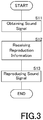
- the sound signal obtainer 141, the reproduction information receiver 142, and the reproducer 143 execute processes S11, S12, and S13 shown in a flowchart of FIG. 3 , respectively.
- the program needs not to be stored in the flash memory 14.
- the processor 12 may download the program from other devices such as a server, and temporarily store it in the RAM 13, if necessary.
- the display 15 is constituted by an LCD, or the like.
- the display 15 displays a setting screen of the reproduction information as shown in FIG. 4 , for example.
- the user I/F 16 is an example of an operation portion.
- the user I/F 16 is constituted by a mouse, a keyboard, a touch panel, or the like.
- the user I/F 17 receives an operation of a user.
- the touch panel may be laminated on the display 15.
- the audio I/F 17 is constituted by an analog audio terminal, a digital audio terminal, or the like.
- the audio I/F 17 is connected to a plurality of speakers 501 through 521.
- the reproducer 143 of the processor 12 outputs a sound signal to the plurality of speakers 501 through 521 via the audio I/F 17.
- the sound signal obtainer 141 of the processor 12 obtains the sound signal of the sound source, which has been received via the communicator 11 (S11). Further, the sound signal of the sound source may be obtained via the audio I/F 17, rather than the communicator 11. Further, the sound signal of the sound source may be stored in the flash memory 14.
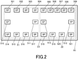
- FIG. 2 is a plan view showing an arrangement of speakers in a room, serving as an example of a sound space, and a concept of an area.
- a room R1 has a rectangular shape when viewed in plan view, as an example.
- a plurality of speakers 501 through 521 are disposed in the room R1, a plurality of speakers 501 through 521 are disposed.
- the speakers 501 through 509 are arranged side by side along a first long side of the room R1 when viewed in plan view.
- the speakers 514 through 521 are arranged side by side along a second long side of the room R1 when viewed in plan view.
- the speaker 510 is disposed on a first short side of the room R1 when viewed in plan view.
- the speaker 513 is disposed on a second short side of the room R1 when viewed in plan view.
- the speakers 511 and 512 are disposed near the center of the room R1 when viewed in plan view.
- the room R1 has a plurality of areas.
- the room R1 has a first area Z1, a second area Z2, and a third area Z3.
- Each of the areas Z1, Z2, and Z3 is an area to which a sound signal is outputted.
- the plurality of areas Z1, Z2, and Z3 are disposed in the room R1.
- an area to which a sound signal is outputted is located indoors.
- the area may be located outdoors.
- the area Z1 is constituted by the speakers 501 through 504, the speakers 510 and 511, and the speakers 514 through 517. Further, the area Z2 is constituted by the speakers 505 through 509, the speakers 512 and 513, and the speakers 518 through 521. Further, the area Z3 is constituted by all the speakers 501 through 521.
- the sound signal output device 1 receives a setting of reproduction information indicating which sound source's sound signal should be outputted to each of the plurality of areas(S12) .
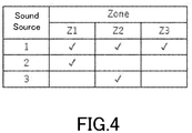
- FIG. 4 is a view showing an example of reproduction information.
- the reproduction information is information indicating to which area a sound signal is outputted for each sound source.
- the reproduction information is information indicating which sound source's sound signal is outputted for each area.
- the processor 12 displays the reproduction information on the display 15.
- a user edits the reproduction information using the user I/F 16.
- a user specifies an area to which a sound signal is outputted for each sound source. In other words, a user specifies which sound source's sound signal to be outputted to each of a plurality of areas.
- sound signals of the sound source 1 and the sound source 2 are outputted to the area Z1.
- Sound signals of the sound source 1 and the sound source 3 are outputted to the area Z2.
- the sound signal of the sound source 1 is outputted to the area Z3.
- the sound signal of sound source 1 is outputted to all the areas.
- the sound signal of the sound source 2 is outputted to only the area Z1.
- the sound signal of the sound source 3 is outputted to only the area Z2.
- the reproducer 143 outputs the sound signal of the sound source 1 to all the speakers 501 through 521. This enables that the sound of sound source 1 can be heard at any position in the area Z3.
- the reproducer 143 outputs the sound signal of the sound source 2 to the speakers 501 through 504, the speakers 510 and 511, and the speakers 514 through 517 in the area Z1. This enables that the sound of sound source 2 can be heard at a position in the area Z1.
- the reproducer 143 outputs the sound signal of the sound source 3 to the speakers 505 through 509, the speakers 512 and 513, and the speakers 518 through 521 in the area Z2. This enables that the sound of sound source 3 can be heard at a position in the area Z2.
- the sound signal output device 1 can output a sound signal of any optional sound source to each of a plurality of areas. For instance, in an attraction of a theme park, a user can use the sound signal output device 1 to reproduce sound of footsteps, as the sound source 1, in all the areas. Therefore, an attraction user hears the footsteps at any position in the attraction. Further, with respect to each attraction object, a user can use the sound signal output device 1 to reproduce sounds while specifying an area. Thus, an attraction user can hear sounds of different objects in each of areas, while hearing the same sound (for example, footsteps) in all the areas of the attraction.
- the reproducer 143 may perform sound-image localization processing in which a sound image of each sound source is localized in the corresponding area.
- the reproducer 143 obtains position information that indicates the location of each speaker disposed in the plurality of areas.
- the position information of speakers may be stored in the flash memory 14, or a user may input it, as necessary, by using the sound signal output device 1.
- the reproducer 143 calculates a level balance of sound signals to be outputted to the plurality of speakers such that each sound source's sound signal is localized in the corresponding area based on the position information of speakers, and adjusts a level of each of the sound signals.
- the reproducer 143 may adjust output timing of each of sound signals to be outputted to the plurality of speakers such that each sound source's sound signal is localized in the corresponding area. This can reduce the possibility that the sound outputted to each area is leaked to other areas and made audible.
- the reproducer 143 is not necessary to output a sound signal of each sound source to all the speakers each of which is disposed in the corresponding area.
- the reproducer 143 may output a sound signal of the sound source 1 to the speakers 501, 509, 514, and 521 which are located at four corners of the room R1.
- FIG. 5 is a view showing an example of reproduction information in accordance with a modification 1.
- the reproduction information may include information indicating to which area a sound signal is outputted for each speaker.
- the reproduction information includes speaker specification information that specifies at least one speaker to be used in each of a plurality of areas.
- the speakers 501 through 504, the speakers 510 and 511, and the speakers 514 through 517 are used in the area Z1.
- the speakers 505 through 509, the speakers 512 and 513, and the speakers 518 through 521 are used in the area Z2. All the speakers 501 through 521 are used in the area Z3.
- a user may specify the speakers 501, 509, 514, and 521, as speakers to be used in the area Z3.
- the reproducer 143 outputs a sound signal of the sound source specified in the area Z3 (sound signal of the sound source 1 in the example of FIG. 4 ) to the speakers 501, 509, 514, and 521 that are located at four corners of the room R1.
- the area Z3 still corresponds to the entire of the room R1. Therefore, a user can use sound signal output device 1 to reproduce sound of footsteps, as the sound source 1, in all the areas of the attraction in a theme park, for example.
- speakers to be used in the area Z1 a user specifies the speakers 501 through 503, the speaker 510, and the speakers 514 through 516 in the example of FIG. 7 . Further, as speakers to be used in the area Z2, a user specifies the speakers 504 through 509, the speakers 511, 512, and 513, and the speakers 517 through 521.
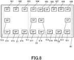
- the reproducer 143 When a user specifies the speakers as shown in FIG. 7 , the reproducer 143 outputs a sound signal of the sound source specified in the area Z1 (the sound source 1 and the sound source 2 in the example of FIG. 4 ) to the speakers 501 through 503, the speaker 510, and the speakers 514 through 516, as shown in FIG. 8 . Further, the reproducer 143 outputs a sound signal of the sound source specified in the area Z2 (the sound source 1 and the sound source 3 in the example of FIG. 4 ) to the speakers 504 through 509, the speakers 511, 512, and 513, and the speakers 517 through 521.
- a sound of the sound source 2 is reproduced in the area where the speakers 501 through 503, the speaker 510, and the speakers 514 through 516 are disposed.
- a sound of the sound source 3 is reproduced in the area where the speakers 504 through 509, the speakers 511, 512, and 513, and the speakers 517 through 521 are disposed. In other words, the ranges covered by the areas Z1 and Z2 are changed.
- FIG. 9 is a view showing an example of reproduction information in accordance with a modification 2.
- the reproduction information may include localization information that specifies a localization position of a sound source.
- the localization information is three-dimensional coordinates whose origin is located at a predetermined position of the room R1, for example.
- the localization information is three-dimensional coordinates, but may be two-dimensional (plan) coordinates.
- the reproducer 143 calculates a level balance of sound signals to be outputted to the plurality of speakers such that a sound image of each sound source is localized at the corresponding position based on the localization information and the position information of speakers, and adjusts a level of each of the sound signals.
- the position information of speakers may be stored in the flash memory 14 as mentioned above, or a user may input it, as necessary, by using the sound signal output device 1. Further, the reproducer 143 may adjust output timing of each of sound signals to be outputted to the plurality of speakers such that each sound source's sound signal is localized at the corresponding position.
- a user can use the sound signal output device 1 to localize a sound image at a position intended by the user, for each attraction object.
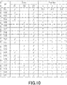
- FIG. 10 is a view showing an example of reproduction information in accordance with a modification 3.
- the reproduction information may include position information that specifies the location of each speaker.
- the position information of speakers shown in FIG. 10 is also three-dimensional coordinates whose origin is located at a predetermined position in the room R1, for example.
- the position information of speakers is three-dimensional coordinates, but may be two-dimensional (plan) coordinates.
- the reproducer 143 calculates a level balance of sound signals to be outputted to the plurality of speakers based on the edited position information of speakers, and adjusts a level of each of the sound signals.
- a user may use the sound signal output device 1 to add or remove the speaker to or from the reproduction information.
- a user can use the sound signal output device 1 to reproduce the sound of each sound source at a localization position and in an area intended by the user.
- FIG. 11 is a block diagram showing a configuration of a sound signal output device 1A.
- the same reference numerals are assigned to the same configurations in the sound signal output device 1 of FIG. 1 , and the description thereof is omitted.
- FIG. 12 is a flowchart showing an operation of the sound signal output device 1A. The same reference numerals are assigned to the same processing in the flowchart of FIG. 3 , and the description thereof is omitted.
- the audio I/F 17 is not included in the sound signal output device 1A. Further, instead of a function of the reproducer 143, an outputter 144 is included in the processor 12.
- the sound signal output device 1A is also constituted by a personal computer, a smart phone, a tablet computer, or the like. Further, audio equipment, such as an audio mixer, is also an example of the sound signal output device.
- the sound signal output device 1A receives an edit of reproduction information.
- the reproduction information shown in FIGS. 4 through 7 and FIGS. 9 and 10 is displayed on the display 15, and the edit of reproduction information is received from a user via the user I/F 16.
- the outputter 144 of the processor 12 After a user completes the edit, the outputter 144 of the processor 12 outputs reproduction information and a sound signal (S103).
- the sound signal and the reproduction information may be outputted to the flash memory 14 and stored therein, or may be outputted to other devices, such as a server, via the communicator 11.
- the device After obtaining the reproduction information and the sound signal, the device reproduces the sound signal of each sound source based on the reproduction information, like the reproducer 143 shown in FIG. 1 .
- a user can use the sound signal output device 1A to produce reproduction information that specifies to which area of a plurality of areas a sound signal is outputted for each sound source.
- a user can produce the reproduction information in advance, which is different from the sound signal output device 1 used in an attraction of a theme park or the like, for example.
- a user may also use the sound signal output device 1 to edit the reproduction information, which is produced in advance by using the sound signal output device 1A, so as to match an actual environment.
Landscapes
- Physics & Mathematics (AREA)
- Engineering & Computer Science (AREA)
- Acoustics & Sound (AREA)
- Signal Processing (AREA)
- Health & Medical Sciences (AREA)
- General Health & Medical Sciences (AREA)
- Otolaryngology (AREA)
- Circuit For Audible Band Transducer (AREA)
- Stereophonic System (AREA)
Abstract
Description
- One embodiment of the present application relates to a sound signal output method, a sound signal output device and a program executable by the sound signal output device to perform the sound signal output method.
- Unexamined Japanese Patent Publication No.
2017-41897 - The device disclosed in Unexamined Japanese Patent Publication No.
2017-41897 - An object of one embodiment of the present application is to provide a sound signal output method and a sound signal output device capable of outputting a sound signal of any optional sound source to each of a plurality of areas.
- The sound signal output method of outputting sound to a plurality of areas in accordance with one embodiment of the present application obtains a sound signal of a sound source, receives a setting of reproduction information indicating whether or not to output the sound signal of the above-mentioned sound source to each of the plurality of areas where the above-mentioned sound signal is to be output, and outputs the above-mentioned reproduction information and the above-mentioned sound signal, or reproduces the above-mentioned sound signal based on the above-mentioned reproduction information.
- According to one embodiment of the present application, a sound signal of any optional sound source can be outputted to each of a plurality of areas.
-
-
FIG. 1 is a block diagram showing a configuration of a soundsignal output device 1. -
FIG. 2 is a plan view showing an arrangement of speakers in a room, serving as an example of a sound space, and a concept of an area. -
FIG. 3 is a flowchart showing an operation of the soundsignal output device 1. -
FIG. 4 is a view showing an example of reproduction information. -
FIG. 5 is a view showing an example of the reproduction information. -
FIG. 6 is a view showing an example of the reproduction information. -
FIG. 7 is a view showing an example of the reproduction information. -
FIG. 8 is a plan view showing an arrangement of speakers in a room, serving as an example of sound space, and a concept of an area. -
FIG. 9 is a view showing an example of reproduction information. -
FIG. 10 is a view showing an example of the reproduction information. -
FIG. 11 is a block diagram showing a configuration of a soundsignal output device 1A. -
FIG. 12 is a flowchart showing an operation of the soundsignal output device 1A. -
FIG. 1 is a block diagram showing a configuration of a soundsignal output device 1. The soundsignal output device 1 includes acommunicator 11, aprocessor 12, aRAM 13, aflash memory 14, adisplay 15, a user I/F 16, and an audio I/F 17. - The sound
signal output device 1 is constituted by a personal computer, a smart phone, a tablet computer, or the like. Further, audio equipment such as an audio mixer is also an example of the sound signal output device. - The
communicator 11 communicates with other devices such as a server. Thecommunicator 11, for example, has a wireless-communication function such as Bluetooth (registered trademark) or Wi-Fi (registered trademark), a cable-communication function such as a USB or a LAN, or the like. Thecommunicator 11 receives a sound signal of a sound source, for example. - The
processor 12 is constituted by a CPU, a DSP, an SoC (System on a Chip), or the like. Theprocessor 12 reads out a program from theflash memory 14 serving as a storage medium, and temporarily stores it in theRAM 13 to execute various kinds of operations. By using the program which has been read out, theprocessor 12 achieves functional configurations such as a sound signal obtainer 141, areproduction information receiver 142, and areproducer 143. The sound signal obtainer 141, thereproduction information receiver 142, and the reproducer 143 execute processes S11, S12, and S13 shown in a flowchart ofFIG. 3 , respectively. Note that, the program needs not to be stored in theflash memory 14. For instance, theprocessor 12 may download the program from other devices such as a server, and temporarily store it in theRAM 13, if necessary. - The
display 15 is constituted by an LCD, or the like. Thedisplay 15 displays a setting screen of the reproduction information as shown inFIG. 4 , for example. - The user I/
F 16 is an example of an operation portion. The user I/F 16 is constituted by a mouse, a keyboard, a touch panel, or the like. The user I/F 17 receives an operation of a user. Note that, the touch panel may be laminated on thedisplay 15. - The audio I/
F 17 is constituted by an analog audio terminal, a digital audio terminal, or the like. The audio I/F 17 is connected to a plurality ofspeakers 501 through 521. The reproducer 143 of theprocessor 12 outputs a sound signal to the plurality ofspeakers 501 through 521 via the audio I/F 17. - The sound signal obtainer 141 of the
processor 12 obtains the sound signal of the sound source, which has been received via the communicator 11 (S11). Further, the sound signal of the sound source may be obtained via the audio I/F 17, rather than thecommunicator 11. Further, the sound signal of the sound source may be stored in theflash memory 14. -
FIG. 2 is a plan view showing an arrangement of speakers in a room, serving as an example of a sound space, and a concept of an area. A room R1 has a rectangular shape when viewed in plan view, as an example. In the room R1, a plurality ofspeakers 501 through 521 are disposed. Thespeakers 501 through 509 are arranged side by side along a first long side of the room R1 when viewed in plan view. Thespeakers 514 through 521 are arranged side by side along a second long side of the room R1 when viewed in plan view. Thespeaker 510 is disposed on a first short side of the room R1 when viewed in plan view. Thespeaker 513 is disposed on a second short side of the room R1 when viewed in plan view. Thespeakers - The room R1 has a plurality of areas. In the example of
FIG. 2 , the room R1 has a first area Z1, a second area Z2, and a third area Z3. Each of the areas Z1, Z2, and Z3 is an area to which a sound signal is outputted. Note that, in this example, the plurality of areas Z1, Z2, and Z3 are disposed in the room R1. However, it is not limited that an area to which a sound signal is outputted is located indoors. The area may be located outdoors. - In the example of
FIG. 2 , the area Z1 is constituted by thespeakers 501 through 504, thespeakers speakers 514 through 517. Further, the area Z2 is constituted by thespeakers 505 through 509, thespeakers speakers 518 through 521. Further, the area Z3 is constituted by all thespeakers 501 through 521. - The sound
signal output device 1 receives a setting of reproduction information indicating which sound source's sound signal should be outputted to each of the plurality of areas(S12) . -
FIG. 4 is a view showing an example of reproduction information. As shown inFIG. 4 , the reproduction information is information indicating to which area a sound signal is outputted for each sound source. In other words, the reproduction information is information indicating which sound source's sound signal is outputted for each area. Theprocessor 12 displays the reproduction information on thedisplay 15. A user edits the reproduction information using the user I/F 16. A user specifies an area to which a sound signal is outputted for each sound source. In other words, a user specifies which sound source's sound signal to be outputted to each of a plurality of areas. - In the example of
FIG. 4 , sound signals of thesound source 1 and thesound source 2 are outputted to the area Z1. Sound signals of thesound source 1 and thesound source 3 are outputted to the area Z2. The sound signal of thesound source 1 is outputted to the area Z3. In other words, the sound signal ofsound source 1 is outputted to all the areas. The sound signal of thesound source 2 is outputted to only the area Z1. The sound signal of thesound source 3 is outputted to only the area Z2. After a user completes the edit, thereproducer 143 of theprocessor 12 reproduces the sound signal of each sound source based on the reproduction information (S13) . - The
reproducer 143 outputs the sound signal of thesound source 1 to all thespeakers 501 through 521. This enables that the sound ofsound source 1 can be heard at any position in the area Z3. Thereproducer 143 outputs the sound signal of thesound source 2 to thespeakers 501 through 504, thespeakers speakers 514 through 517 in the area Z1. This enables that the sound ofsound source 2 can be heard at a position in the area Z1. Thereproducer 143 outputs the sound signal of thesound source 3 to thespeakers 505 through 509, thespeakers speakers 518 through 521 in the area Z2. This enables that the sound ofsound source 3 can be heard at a position in the area Z2. - In this way, the sound
signal output device 1 can output a sound signal of any optional sound source to each of a plurality of areas. For instance, in an attraction of a theme park, a user can use the soundsignal output device 1 to reproduce sound of footsteps, as thesound source 1, in all the areas. Therefore, an attraction user hears the footsteps at any position in the attraction. Further, with respect to each attraction object, a user can use the soundsignal output device 1 to reproduce sounds while specifying an area. Thus, an attraction user can hear sounds of different objects in each of areas, while hearing the same sound (for example, footsteps) in all the areas of the attraction. - Note that, the
reproducer 143 may perform sound-image localization processing in which a sound image of each sound source is localized in the corresponding area. In this case, thereproducer 143 obtains position information that indicates the location of each speaker disposed in the plurality of areas. The position information of speakers may be stored in theflash memory 14, or a user may input it, as necessary, by using the soundsignal output device 1. Thereproducer 143 calculates a level balance of sound signals to be outputted to the plurality of speakers such that each sound source's sound signal is localized in the corresponding area based on the position information of speakers, and adjusts a level of each of the sound signals. Further, thereproducer 143 may adjust output timing of each of sound signals to be outputted to the plurality of speakers such that each sound source's sound signal is localized in the corresponding area. This can reduce the possibility that the sound outputted to each area is leaked to other areas and made audible. - Note that, the
reproducer 143 is not necessary to output a sound signal of each sound source to all the speakers each of which is disposed in the corresponding area. For instance, thereproducer 143 may output a sound signal of thesound source 1 to thespeakers -
FIG. 5 is a view showing an example of reproduction information in accordance with amodification 1. As shown inFIG. 5 , the reproduction information may include information indicating to which area a sound signal is outputted for each speaker. In other words, the reproduction information includes speaker specification information that specifies at least one speaker to be used in each of a plurality of areas. - In the example of
FIG. 5 , thespeakers 501 through 504, thespeakers speakers 514 through 517 are used in the area Z1. Thespeakers 505 through 509, thespeakers speakers 518 through 521 are used in the area Z2. All thespeakers 501 through 521 are used in the area Z3. - On the other hand, as shown in
FIG. 6 , a user may specify thespeakers reproducer 143 outputs a sound signal of the sound source specified in the area Z3 (sound signal of thesound source 1 in the example ofFIG. 4 ) to thespeakers signal output device 1 to reproduce sound of footsteps, as thesound source 1, in all the areas of the attraction in a theme park, for example. - On the other hand, as speakers to be used in the area Z1, a user specifies the
speakers 501 through 503, thespeaker 510, and thespeakers 514 through 516 in the example ofFIG. 7 . Further, as speakers to be used in the area Z2, a user specifies thespeakers 504 through 509, thespeakers speakers 517 through 521. - When a user specifies the speakers as shown in
FIG. 7 , thereproducer 143 outputs a sound signal of the sound source specified in the area Z1 (thesound source 1 and thesound source 2 in the example ofFIG. 4 ) to thespeakers 501 through 503, thespeaker 510, and thespeakers 514 through 516, as shown inFIG. 8 . Further, thereproducer 143 outputs a sound signal of the sound source specified in the area Z2 (thesound source 1 and thesound source 3 in the example ofFIG. 4 ) to thespeakers 504 through 509, thespeakers speakers 517 through 521. - Thus, a sound of the
sound source 2 is reproduced in the area where thespeakers 501 through 503, thespeaker 510, and thespeakers 514 through 516 are disposed. A sound of thesound source 3 is reproduced in the area where thespeakers 504 through 509, thespeakers speakers 517 through 521 are disposed. In other words, the ranges covered by the areas Z1 and Z2 are changed. - In this way, by specifying speakers to be used in each area, a user can easily change a range covered by each area.
-
FIG. 9 is a view showing an example of reproduction information in accordance with amodification 2. As shown inFIG. 9 , the reproduction information may include localization information that specifies a localization position of a sound source. The localization information is three-dimensional coordinates whose origin is located at a predetermined position of the room R1, for example. In the example ofFIG. 9 , the localization information is three-dimensional coordinates, but may be two-dimensional (plan) coordinates. - The
reproducer 143 calculates a level balance of sound signals to be outputted to the plurality of speakers such that a sound image of each sound source is localized at the corresponding position based on the localization information and the position information of speakers, and adjusts a level of each of the sound signals. The position information of speakers may be stored in theflash memory 14 as mentioned above, or a user may input it, as necessary, by using the soundsignal output device 1. Further, thereproducer 143 may adjust output timing of each of sound signals to be outputted to the plurality of speakers such that each sound source's sound signal is localized at the corresponding position. Thus, for instance, a user can use the soundsignal output device 1 to localize a sound image at a position intended by the user, for each attraction object. -
FIG. 10 is a view showing an example of reproduction information in accordance with amodification 3. As shown inFIG. 10 , the reproduction information may include position information that specifies the location of each speaker. The position information of speakers shown inFIG. 10 is also three-dimensional coordinates whose origin is located at a predetermined position in the room R1, for example. In the example ofFIG. 10 , the position information of speakers is three-dimensional coordinates, but may be two-dimensional (plan) coordinates. When the location of each speaker is changed, a user uses soundsignal output device 1 to edit the position information of speakers, which is included in the reproduction information. Accordingly, when performing the sound-image localization processing of each sound source, thereproducer 143 calculates a level balance of sound signals to be outputted to the plurality of speakers based on the edited position information of speakers, and adjusts a level of each of the sound signals. - Alternatively, if a speaker is disposed additionally or removed, a user may use the sound
signal output device 1 to add or remove the speaker to or from the reproduction information. - Accordingly, even if the location of each speaker is changed, a user can use the sound
signal output device 1 to reproduce the sound of each sound source at a localization position and in an area intended by the user. - Next,
FIG. 11 is a block diagram showing a configuration of a soundsignal output device 1A. The same reference numerals are assigned to the same configurations in the soundsignal output device 1 ofFIG. 1 , and the description thereof is omitted.FIG. 12 is a flowchart showing an operation of the soundsignal output device 1A. The same reference numerals are assigned to the same processing in the flowchart ofFIG. 3 , and the description thereof is omitted. - Unlike the sound
signal output device 1, the audio I/F 17 is not included in the soundsignal output device 1A. Further, instead of a function of thereproducer 143, anoutputter 144 is included in theprocessor 12. The soundsignal output device 1A is also constituted by a personal computer, a smart phone, a tablet computer, or the like. Further, audio equipment, such as an audio mixer, is also an example of the sound signal output device. - Like the sound
signal output device 1, the soundsignal output device 1A receives an edit of reproduction information. In other words, in the soundsignal output device 1A, the reproduction information shown inFIGS. 4 through 7 andFIGS. 9 and10 is displayed on thedisplay 15, and the edit of reproduction information is received from a user via the user I/F 16. - After a user completes the edit, the
outputter 144 of theprocessor 12 outputs reproduction information and a sound signal (S103). The sound signal and the reproduction information may be outputted to theflash memory 14 and stored therein, or may be outputted to other devices, such as a server, via thecommunicator 11. - After obtaining the reproduction information and the sound signal, the device reproduces the sound signal of each sound source based on the reproduction information, like the
reproducer 143 shown inFIG. 1 . - In this way, assuming a reproduction environment, a user can use the sound
signal output device 1A to produce reproduction information that specifies to which area of a plurality of areas a sound signal is outputted for each sound source. In other words, by using the soundsignal output device 1A, a user can produce the reproduction information in advance, which is different from the soundsignal output device 1 used in an attraction of a theme park or the like, for example. In this case, a user may also use the soundsignal output device 1 to edit the reproduction information, which is produced in advance by using the soundsignal output device 1A, so as to match an actual environment. - The description of the present embodiments is illustrative in all respects and is not to be construed restrictively. The scope of the present application is indicated by the appended claims rather than by the above-mentioned embodiments. Furthermore, the scope of the present application includes the scope of the claims and a range equivalent thereto.
Claims (12)
- A sound signal output method of outputting sound to a plurality of areas, the method comprising:obtaining a sound signal of a sound source (S11);receiving a setting of reproduction information indicating whether or not to output the sound signal of the sound source to each of the plurality of areas where the sound signal is to be output (S12); andoutputting the reproduction information and the sound signal (S103), or reproducing the sound signal based on the reproduction information (S13).
- The sound signal output method according to claim 1, wherein the reproduction information includes speaker specification information specifying at least one speaker to be used in each of the plurality of areas.
- The sound signal output method according to claim 1 or claim 2, wherein the reproduction information includes position information indicating location of speakers disposed in the plurality of areas.
- The sound signal output method according to one of claims 1 to 3, wherein the reproduction information includes localization information indicating a localization position of the sound source.
- The sound signal output method according to one of claims 1 to 4, wherein the plurality of areas are set in a single room.
- A sound signal output device (1A) for outputting sound to a plurality of areas, the sound signal output device (1A) comprising:a sound signal obtainer (141), obtaining a sound signal of a sound source;a reproduction information receiver (142), receiving a setting of reproduction information indicating whether or not to output the sound signal of the sound source to each of the plurality of areas where the sound signal is to be output; andan outputter (144), outputting the reproduction information and the sound signal.
- A sound signal output device (1) for outputting sound to a plurality of areas, the sound signal output device (1) comprising:a sound signal obtainer (141), obtaining a sound signal of a sound source;a reproduction information receiver (142), receiving a setting of reproduction information indicating whether or not to output the sound signal of the sound source to each of the plurality of areas where the sound signal is to be output; anda reproducer (143), reproducing the sound signal based on the reproduction information.
- The sound signal output device according to claim 6 or claim 7, wherein the reproduction information includes speaker specification information specifying at least one speaker to be used in each of the plurality of areas.
- The sound signal output device according to one of claims 6 to 8, wherein the reproduction information includes position information indicating location of speakers disposed in the plurality of areas.
- The sound signal output device according to one of claims 6 to 9, wherein the reproduction information includes localization information indicating a localization position of the sound source.
- The sound signal output device according to one of claims 6 to 10, wherein the plurality of areas are set in a single room.
- A program executable by a sound signal output device to perform:obtaining a sound signal of a sound source (S11);receiving a setting of reproduction information indicating whether or not to output the sound signal of the sound source to each of a plurality of areas where the sound signal is to be output (S12); andoutputting the reproduction information and the sound signal (S103), or reproducing the sound signal based on the reproduction information (S13).
Applications Claiming Priority (1)
| Application Number | Priority Date | Filing Date | Title |
|---|---|---|---|
| JP2020052824A JP7443870B2 (en) | 2020-03-24 | 2020-03-24 | Sound signal output method and sound signal output device |
Publications (1)
| Publication Number | Publication Date |
|---|---|
| EP3886465A1 true EP3886465A1 (en) | 2021-09-29 |
Family
ID=74859304
Family Applications (1)
| Application Number | Title | Priority Date | Filing Date |
|---|---|---|---|
| EP21160960.7A Pending EP3886465A1 (en) | 2020-03-24 | 2021-03-05 | Sound signal output method, sound signal output device and program |
Country Status (4)
| Country | Link |
|---|---|
| US (1) | US11653165B2 (en) |
| EP (1) | EP3886465A1 (en) |
| JP (1) | JP7443870B2 (en) |
| CN (1) | CN113453125B (en) |
Citations (4)
| Publication number | Priority date | Publication date | Assignee | Title |
|---|---|---|---|---|
| US20050195999A1 (en) * | 2004-03-04 | 2005-09-08 | Yamaha Corporation | Audio signal processing system |
| WO2015127082A1 (en) * | 2014-02-21 | 2015-08-27 | Sonos, Inc. | Media content based on playback zone awareness |
| WO2016048381A1 (en) * | 2014-09-26 | 2016-03-31 | Nunntawi Dynamics Llc | Audio system with configurable zones |
| JP2017041897A (en) | 2011-07-01 | 2017-02-23 | ドルビー ラボラトリーズ ライセンシング コーポレイション | Systems and tools for improved 3D audio creation and presentation |
Family Cites Families (12)
| Publication number | Priority date | Publication date | Assignee | Title |
|---|---|---|---|---|
| JP2002369279A (en) | 2001-06-04 | 2002-12-20 | Kenwood Corp | Audio equipment and audio system |
| JP2006512022A (en) * | 2003-01-23 | 2006-04-06 | ハーマン ベッカー オートモーティブ システムズ ゲーエムベーハー | Audio system with balance setting based on information address |
| AU2007312597B2 (en) * | 2006-10-16 | 2011-04-14 | Dolby International Ab | Apparatus and method for multi -channel parameter transformation |
| JP4942182B2 (en) | 2007-02-28 | 2012-05-30 | 株式会社第一興商 | Karaoke system |
| JP2009143495A (en) | 2007-12-17 | 2009-07-02 | Fujitsu Ten Ltd | Acoustic control apparatus |
| JP2009303134A (en) | 2008-06-17 | 2009-12-24 | Panasonic Corp | Public-address system |
| CA3157717A1 (en) * | 2011-07-01 | 2013-01-10 | Dolby Laboratories Licensing Corporation | System and method for adaptive audio signal generation, coding and rendering |
| JP6111611B2 (en) | 2012-11-16 | 2017-04-12 | ヤマハ株式会社 | Audio amplifier |
| CN104982043A (en) * | 2013-02-05 | 2015-10-14 | 皇家飞利浦有限公司 | An audio apparatus and method therefor |
| WO2017087564A1 (en) * | 2015-11-20 | 2017-05-26 | Dolby Laboratories Licensing Corporation | System and method for rendering an audio program |
| JP2019129441A (en) | 2018-01-25 | 2019-08-01 | 株式会社デンソーテン | Music provision system and music provision method |
| TWI687915B (en) * | 2018-07-06 | 2020-03-11 | 友達光電股份有限公司 | Dynamic video wall and playing method thereof |
-
2020
- 2020-03-24 JP JP2020052824A patent/JP7443870B2/en active Active
-
2021
- 2021-03-05 EP EP21160960.7A patent/EP3886465A1/en active Pending
- 2021-03-08 US US17/194,509 patent/US11653165B2/en active Active
- 2021-03-10 CN CN202110260935.3A patent/CN113453125B/en active Active
Patent Citations (4)
| Publication number | Priority date | Publication date | Assignee | Title |
|---|---|---|---|---|
| US20050195999A1 (en) * | 2004-03-04 | 2005-09-08 | Yamaha Corporation | Audio signal processing system |
| JP2017041897A (en) | 2011-07-01 | 2017-02-23 | ドルビー ラボラトリーズ ライセンシング コーポレイション | Systems and tools for improved 3D audio creation and presentation |
| WO2015127082A1 (en) * | 2014-02-21 | 2015-08-27 | Sonos, Inc. | Media content based on playback zone awareness |
| WO2016048381A1 (en) * | 2014-09-26 | 2016-03-31 | Nunntawi Dynamics Llc | Audio system with configurable zones |
Also Published As
| Publication number | Publication date |
|---|---|
| JP2021153258A (en) | 2021-09-30 |
| CN113453125B (en) | 2023-11-07 |
| US20210306787A1 (en) | 2021-09-30 |
| US11653165B2 (en) | 2023-05-16 |
| JP7443870B2 (en) | 2024-03-06 |
| CN113453125A (en) | 2021-09-28 |
Similar Documents
| Publication | Publication Date | Title |
|---|---|---|
| CN109831735B (en) | Audio playing method, device, system and storage medium suitable for indoor environment | |
| US11758329B2 (en) | Audio mixing based upon playing device location | |
| CN1682567B (en) | smart speaker | |
| US5982902A (en) | System for generating atmospheric quasi-sound for audio performance | |
| EP2926570B1 (en) | Image generation for collaborative sound systems | |
| US12437739B2 (en) | Method and apparatus for determining volume adjustment ratio information, device, and storage medium | |
| EP3236345A1 (en) | An apparatus and associated methods | |
| US20090262946A1 (en) | Augmented reality enhanced audio | |
| US9769585B1 (en) | Positioning surround sound for virtual acoustic presence | |
| CN112492097A (en) | Audio playing method, device, terminal and computer readable storage medium | |
| JP6522105B2 (en) | Audio signal reproduction apparatus, audio signal reproduction method, program, and recording medium | |
| WO2022113289A1 (en) | Live data delivery method, live data delivery system, live data delivery device, live data reproduction device, and live data reproduction method | |
| WO2022113393A1 (en) | Live data delivery method, live data delivery system, live data delivery device, live data reproduction device, and live data reproduction method | |
| CN116347320A (en) | Audio playback method and electronic device | |
| JP2014103456A (en) | Audio amplifier | |
| US20240339094A1 (en) | Audio synthesis method, and computer device and computer-readable storage medium | |
| US11653165B2 (en) | Sound signal output method and sound signal output device | |
| CN114520950A (en) | Audio output method and device, electronic equipment and readable storage medium | |
| JP7472091B2 (en) | Online call management device and online call management program | |
| CN112307161B (en) | Method and apparatus for playing audio | |
| WO2016009850A1 (en) | Sound signal reproduction device, sound signal reproduction method, program, and storage medium | |
| KR102523048B1 (en) | Sound conversion system and method in virtual reality | |
| CN113709652B (en) | Audio play control method and electronic equipment | |
| EP4149124A1 (en) | Information processing method, information processing apparatus and program | |
| JP2012169704A (en) | Image information processor and control method of the same |
Legal Events
| Date | Code | Title | Description |
|---|---|---|---|
| PUAI | Public reference made under article 153(3) epc to a published international application that has entered the european phase |
Free format text: ORIGINAL CODE: 0009012 |
|
| STAA | Information on the status of an ep patent application or granted ep patent |
Free format text: STATUS: THE APPLICATION HAS BEEN PUBLISHED |
|
| AK | Designated contracting states |
Kind code of ref document: A1 Designated state(s): AL AT BE BG CH CY CZ DE DK EE ES FI FR GB GR HR HU IE IS IT LI LT LU LV MC MK MT NL NO PL PT RO RS SE SI SK SM TR |
|
| STAA | Information on the status of an ep patent application or granted ep patent |
Free format text: STATUS: REQUEST FOR EXAMINATION WAS MADE |
|
| 17P | Request for examination filed |
Effective date: 20220223 |
|
| RBV | Designated contracting states (corrected) |
Designated state(s): AL AT BE BG CH CY CZ DE DK EE ES FI FR GB GR HR HU IE IS IT LI LT LU LV MC MK MT NL NO PL PT RO RS SE SI SK SM TR |
|
| STAA | Information on the status of an ep patent application or granted ep patent |
Free format text: STATUS: EXAMINATION IS IN PROGRESS |
|
| 17Q | First examination report despatched |
Effective date: 20220808 |