EP3886429A1 - Information processing apparatus, image capturing apparatus, method, program and storage medium - Google Patents
Information processing apparatus, image capturing apparatus, method, program and storage medium Download PDFInfo
- Publication number
- EP3886429A1 EP3886429A1 EP21163560.2A EP21163560A EP3886429A1 EP 3886429 A1 EP3886429 A1 EP 3886429A1 EP 21163560 A EP21163560 A EP 21163560A EP 3886429 A1 EP3886429 A1 EP 3886429A1
- Authority
- EP
- European Patent Office
- Prior art keywords
- luminance
- subject
- detected
- exposure
- image
- Prior art date
- Legal status (The legal status is an assumption and is not a legal conclusion. Google has not performed a legal analysis and makes no representation as to the accuracy of the status listed.)
- Withdrawn
Links
- 230000010365 information processing Effects 0.000 title claims abstract description 13
- 238000000034 method Methods 0.000 title claims description 25
- 238000001514 detection method Methods 0.000 claims description 40
- 230000008569 process Effects 0.000 claims description 13
- 235000019557 luminance Nutrition 0.000 description 87
- 238000012545 processing Methods 0.000 description 16
- 238000010586 diagram Methods 0.000 description 11
- 230000008859 change Effects 0.000 description 7
- 238000005375 photometry Methods 0.000 description 5
- 238000004891 communication Methods 0.000 description 4
- 230000006870 function Effects 0.000 description 4
- 238000012935 Averaging Methods 0.000 description 2
- 238000012937 correction Methods 0.000 description 2
- 230000000875 corresponding effect Effects 0.000 description 2
- 230000003287 optical effect Effects 0.000 description 2
- 230000009467 reduction Effects 0.000 description 2
- 230000004075 alteration Effects 0.000 description 1
- 238000003705 background correction Methods 0.000 description 1
- 230000005540 biological transmission Effects 0.000 description 1
- 230000000295 complement effect Effects 0.000 description 1
- 230000001276 controlling effect Effects 0.000 description 1
- 238000007796 conventional method Methods 0.000 description 1
- 230000002596 correlated effect Effects 0.000 description 1
- 230000003247 decreasing effect Effects 0.000 description 1
- 230000000694 effects Effects 0.000 description 1
- 238000011156 evaluation Methods 0.000 description 1
- 238000000605 extraction Methods 0.000 description 1
- 230000037308 hair color Effects 0.000 description 1
- 239000000463 material Substances 0.000 description 1
- 229910044991 metal oxide Inorganic materials 0.000 description 1
- 150000004706 metal oxides Chemical class 0.000 description 1
- 238000005070 sampling Methods 0.000 description 1
- 239000004065 semiconductor Substances 0.000 description 1
Images


Classifications
-
- H—ELECTRICITY
- H04—ELECTRIC COMMUNICATION TECHNIQUE
- H04N—PICTORIAL COMMUNICATION, e.g. TELEVISION
- H04N23/00—Cameras or camera modules comprising electronic image sensors; Control thereof
- H04N23/70—Circuitry for compensating brightness variation in the scene
- H04N23/73—Circuitry for compensating brightness variation in the scene by influencing the exposure time
-
- H—ELECTRICITY
- H04—ELECTRIC COMMUNICATION TECHNIQUE
- H04N—PICTORIAL COMMUNICATION, e.g. TELEVISION
- H04N23/00—Cameras or camera modules comprising electronic image sensors; Control thereof
- H04N23/60—Control of cameras or camera modules
- H04N23/61—Control of cameras or camera modules based on recognised objects
- H04N23/611—Control of cameras or camera modules based on recognised objects where the recognised objects include parts of the human body
-
- H—ELECTRICITY
- H04—ELECTRIC COMMUNICATION TECHNIQUE
- H04N—PICTORIAL COMMUNICATION, e.g. TELEVISION
- H04N23/00—Cameras or camera modules comprising electronic image sensors; Control thereof
- H04N23/70—Circuitry for compensating brightness variation in the scene
- H04N23/71—Circuitry for evaluating the brightness variation
Definitions
- the present invention relates to an information processing apparatus, an image capturing apparatus, a method, a program and a storage medium.
- the present invention in its one aspect provides an information processing apparatus as specified in Claims 1 to 8.
- the present invention in its one aspect provides an image capturing apparatus as specified in Claim 9.
- the present invention in its one aspect provides a method as specified in Claim 10.
- the present invention in its one aspect provides a program as specified in Claim 11.
- the present invention in its one aspect provides a storage medium as specified in Claim 12.
- An embodiment of the present invention improves stability in adjusting an exposure to a specific region of a subject.
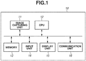
- Fig. 1 is a diagram illustrating an example of a hardware configuration of a camera 10.
- the camera 10 includes an image capturing unit 11, a central processing unit (CPU) 12, a memory 13, an input unit 14, a display unit 15 and a communication unit 16 as hardware components.
- the image capturing unit 11 captures subject images. Details of the image capturing unit 11 are illustrated in Fig. 2 described below.
- the CPU 12 controls the entire camera 10.
- the memory 13 stores programs, images captured by the image capturing unit 11, and setting values.
- the input unit 14 inputs user selection operations and transfers the user selection operations to the CPU 12.
- the display unit 15 displays a screen based on the control of the CPU 12.
- the communication unit 16 connects the camera 10 to a network and controls communication with other apparatuses.
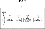
- Fig. 2 is a diagram illustrating an example of the image capturing unit 11.
- the image capturing unit 11 includes a lens 201 and an image sensor 202.
- the lens 201 includes several lenses
- the image sensor 202 is a charge-coupled device (CCD) image sensor or a complementary metal oxide semiconductor (CMOS) image sensor.
- the image capturing unit 11 further includes a correlated double sampling (CDS) circuit 203.
- the CDS circuit 203 reduces noise.
- the image capturing unit 11 further includes a gain control amplifier circuit (automatic gain control (AGC) amplifier circuit) 204 that automatically controls the gain of the camera 10.
- AGC automatic gain control
- the image capturing unit 11 includes an analog-to-digital (A/D) converter 205.
- the A/D converter 205 converts analog signals into digital signals.
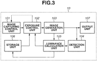
- Fig. 3 is a diagram illustrating an example of a software configuration of the camera 10.
- An image capturing control unit 101 controls the image capturing unit 11.
- An exposure control unit 102 controls an exposure in image capturing.
- An image generation unit 103 generates an image captured at an exposure determined by the exposure control unit 102.
- a detection unit 104 detects a specific object from an image generated by the image generation unit 103.
- a luminance calculation unit 105 calculates a luminance of a predetermined region of an image generated by the image generation unit 103.
- a storage unit 106 stores image-related luminance information or specific object-related information.
- An output unit 107 outputs an image generated by the image generation unit 103 to the outside.
- the lens 201 forms a subject image on the image sensor 202 in the subsequent block. Further, the lens 201 can be formed various lenses such as a prime lens and a zoom lens.
- the image sensor 202 converts the subject image formed via the lens 201 serving as an image capturing optical system into electric signals. Further, an aperture that physically adjusts the amount of light can be provided between the lens 201 and the image sensor 202.
- the CDS circuit 203 executes a CDS process on the electric signals output from the image sensor 202.
- the AGC amplifier circuit 204 amplifies the electric signals output from the CDS circuit 203.
- the A/D converter 205 converts the analog signals amplified by the AGC amplifier circuit 204 into digital signals.
- the image capturing control unit 101 transfers luminance signals and color signals obtained from the image capturing unit 11 to the exposure control unit 102.
- the exposure control unit 102 controls the aperture in the lens 201 of the image capturing unit 11, the shutter speed set by the image sensor 202, and the gain controlled by the AGC amplifier circuit 204. Then, exposure control is automatically performed with a target value determined to retain predetermined brightness of a captured image based on a predefined program diagram.
- the image generation unit 103 generates a captured image captured at an exposure determined by the exposure control unit 102. At this time, various types of general image processing can be performed.
- Examples of the general image processing include gamma correction, white balance processing, color balance processing, sharpness processing, noise reduction processing, aberration correction, and shading correction.
- Various image processing parameters of the image generation unit 103 can be changed based on an exposure level set by the exposure control unit 102. For example, a process of increasing the level of noise reduction processing as the gain controlled by the exposure control unit 102 becomes higher is included.
- the detection unit 104 detects a specific object, such as the face of a person or a human body, from the image on which various types of image processing have been performed by the image generation unit 103 and detects each specific object as a separate object. Further, the type and size of an object to be detected can be predetermined by the detection unit 104 or can be selected by a user as desired. Fig.
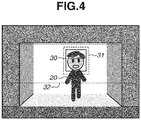
- FIG. 4 is a diagram illustrating how a human body and a face are detected from a captured image.
- an object (person) 20 represents a person walking in an entrance of a building from outside of the building
- a solid-line rectangle 30 and a broken-line rectangle 31 respectively represent a face detection frame and a human body detection frame.
- a dot-line rectangle 32 in Fig. 4 represents a face/human body detectable frame, and only a face or a human body in the frame can be set detectable.
- the position of the face/human body detectable frame can be fixed or can be designated by a user as desired. Further, setting a face detectable frame and a human body detectable frame separately can be allowed.
- the luminance calculation unit 105 calculates a luminance of a specific object detected by the detection unit 104 and containing a human body or the face of a person at a predetermined timing.
- the luminance can be calculated by averaging luminances of a predetermined region containing a detected specific object or by weighted-averaging.
- the predetermined region containing an object can be the entire rectangle frame or can be the entirety or part of the inside of the detected object.
- the detection unit 104 detects a specific face and a human body
- the luminance of the human body at the time of the face detection, the luminance of the face at the time of the face detection, the luminance of the human body at the time of the human body detection, and the difference between the human body luminance as a reference and the face luminance are calculated for each detected specific face and human body.
- the difference between the luminance of the face or human body and the luminance of the entire image is calculated, and in a case where the luminance of the face or human body is relatively lower than the luminance of the entire screen, the scene is determined as a backlight scene (scene determination).
- the storage unit 106 stores luminance information including the various luminances and the luminance difference that are calculated by the luminance calculation unit 105.
- the output unit 107 outputs the image on which various types of image processing have been performed by the image generation unit 103.
- An output destination of the output unit 107 can be a built-in display of the camera 10 or an external terminal apparatus connected via the communication unit 16.
- Fig. 3 illustrates a configuration of the image capturing apparatus 10.
- the image capturing control unit 101, the exposure control unit 102, the image generation unit 103, the detection unit 104, the luminance calculation unit 105, the storage unit 106, and the output unit 107 mainly operate to realize a process illustrated in the flowchart in Fig. 5 .
- a subject environment where the image capturing apparatus 10 is performing image capturing is assumed as follows.
- the person 20 in Fig. 4 is walking into a dark room from the bright outside in a backlight scene where the streams of light are strong during daytime hours.
- the luminance calculation unit 105 determines whether a captured image generated as a result of processing by the image capturing control unit 101, the exposure control unit 102 and the image generation unit 103 is an image of a backlight scene.
- the determination regarding whether an image is of a backlight scene can be made by a publicly-known method based on a difference in luminance between a plurality of predetermined regions in the image.
- a luminance histogram is calculated, and in a case where the proportion of pixels having a luminance higher than or equal to a predetermined value or lower than or equal to a predetermined value is higher than or equal to a predetermined value, the image may be determined as an image of a backlight scene.
- step S101 the human body detection is performed and it is determined whether there is a human body in the image.
- the detection unit 104 detects a human body in step S101 (YES in step S101)
- step S102 it is determined whether predetermined information about human body luminance and face luminance is stored in the storage unit 106.
- the exposure control unit 102 executes exposure control on the human body.
- step S104 it is determined whether a face is detected during the process of adjusting the exposure to the human body in step S103.
- the detection unit 104 detects a face in step S104 (YES in step S104)
- step S105 the human body luminance and the face luminance at the time of the face detection are calculated, and the calculated human body luminance and the calculated face luminance are stored in the storage unit 106.
- FIG. 6 is a table showing calculation results of the human body luminance at the time of the face detection, the face luminance at the time of the face detection, and the difference between the human body luminance as a reference and the face luminance, where the minimum and maximum values of the luminance of the image are respectively set to 0 and 255 with respect to the person 20 in Fig. 4 .
- the luminance calculation unit 105 stores the various types of calculated luminance information about the human body and face in the storage unit 106 in step S105
- the exposure control is executed on the face detected by the detection unit 104 in step S104.
- step S107 the luminance calculation unit 105 determines whether a change in luminance of the image is not greater than or equal to a predetermined value.
- a state where a face is lost refers to a state where a detected face becomes partially or entirely undetectable. This may be due to an effect of a shielding material or may be a state where a face detected by the detection unit 104 becomes undetectable due to a change in orientation of the face.
- a change in the entire image can be determined based on a luminance change in a plurality of predetermined regions in the image or based on a change that is greater than or equal to a predetermined value in a luminance histogram distribution. Further, in a case where both a human body and a face that are detected by the detection unit 104 are lost, the exposure control can be changed to the normal exposure control after a predetermined length of time passes. In the normal exposure control, various general photometry methods, such as average photometry, center-weighted photometry, evaluation photometry, and spot photometry, can be employed with respect to the entire image.
- step S108 the speed of exposure control executed by the exposure control unit 102 with respect to a predetermined target value is increased.
- Fig. 7 is a graph illustrating an example of a difference in speed of exposure control by the exposure control unit 102 in step S108.
- a solid-line represents a case of a normal speed whereas a broken-line represents a case of an increased speed.
- the graph shows that the time to reach the target luminance is shorter in the exposure control specified by the broken-line.
- a means for changing the speed of exposure control executed by the exposure control unit 102 can decrease the resolution of the control of at least one of aperture, gain, and shutter speed per unit time. After the speed of exposure control executed by the exposure control unit 102 is changed in step S108, the exposure control unit 102 obtains the luminance difference between the face luminance and the human body luminance that is stored in the storage unit 106.
- step S109 a target value offset by the luminance difference is set for the human body detected by the detection unit 104, and the exposure control is executed. Since the difference between the human body luminance as a reference and the face luminance that is stored in step S105 in Fig. 6 is +30, the target value is constantly offset by +30 with respect to the luminance of the human body detected by the detection unit 104 so that an exposure suitable for the face is maintained even in a state where only the human body is being detected.
- step S107 in a case where a change in luminance of the image is greater than or equal to the predetermined value (NO in step S107), the correlation of the luminance difference between the face luminance and the human body luminance that is stored in the storage unit 106 may not be established.
- steps S 104 to S106 can be executed to store a face luminance and a human body luminance in the storage unit 106 again.
- the exposure control corresponding to the target value for the face is executed on the human body compared to the normal exposure control, so that underexposure is prevented as illustrated in Fig. 9 .
- the exposure control suitable for the face of the person 20 is executed on the human body of the person 20 at a faster speed than the normal exposure control.
- steps S101 to S109 described above increases the stability of the exposure in a case where a face detected by the detection unit 104 is lost and increases the readiness of the exposure in adjusting the exposure to the same face after the face is lost.
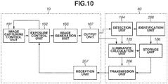
- Fig. 10 is a diagram illustrating a configuration of the image capturing system according to the second embodiment.
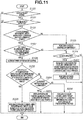
- the image capturing apparatus 10 and a client apparatus 40 mainly operate to realize a process illustrated in a flowchart in Fig. 11 .
- the processes of the respective components 101 to 107 included in the image capturing apparatus 10 and the client apparatus 40 in Fig. 10 are similar to those described in the first embodiment, so that redundant descriptions thereof are omitted.
- a transmission unit 206 of the client apparatus 40 transmits at least an instruction on the exposure control to the image capturing apparatus 10 based on the luminance information obtained from the luminance calculation unit 105 and the storage unit 106.
- a reception unit 207 of the image capturing apparatus 10 receives the instruction from the client apparatus 40 and transmits the instruction at least to the exposure control unit 102.
- An identification unit 208 performs feature amount extraction or pattern matching and identifies an individual of a specific object including a face and a human body detected by the detection unit 104. Further, the image capturing apparatus 10 and the client apparatus 40 can communicate using a local network or can communicate via a global network such as the Internet.
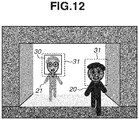
- a subject environment where the image capturing apparatus 10 is performing image capturing is as follows. The person 20 and a person 21 are walking into a dark room from the bright outside in a backlight scene where the streams of light are strong during daytime hours as illustrated in Fig. 12 . Further, processes for the solid-line 30 and the broken-lines 31 in Fig. 12 are similar to those in Fig. 4 , so that redundant descriptions thereof are omitted.
- Steps S100 to S104 and steps S106 to S108 in Fig. 11 are similar to those in the flowchart in Fig. 5 according to the first embodiment, so that redundant descriptions thereof are omitted.
- the identification unit 208 identifies the faces and human bodies and assigns a unique identification (ID) to each of the identified faces and the identified human bodies. Then, the identified faces and human body silhouettes can be stored in association with pieces of information about human body luminance and face luminance in the storage unit 106.
- ID unique identification
- the person 20 in Fig. 12 has the face ID "001" and the human body ID "1001"
- the person 21 in Fig. 12 has the face ID "002" and the human body ID "1002”.
- the detection unit 104 or the identification unit 208 can identify and recognize an individual to some extent based on a feature amount of the face image or the silhouette of the human body using a publicly-known technique.
- two-dimensional coordinates on the image at the time of the human body detection and at the time of the face detection by the detection unit 104 can be stored in association with the detected human body and face in the storage unit 106.
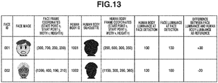
- Fig. 13 is a table showing the pieces of luminance information about the faces and the human bodies of the persons 20 and 21 in Fig.
- the two-dimensional coordinates of the face detection frame and the human body detection frame can be expressed as in the table in Fig. 13 .
- the x- and y-coordinates of a start point of each frame are respectively denoted by x and y
- the width and height of the frame are respectively denoted by v and h.
- maximum values of x, y, v, and h can each be a value that is sufficiently large not to depend on the resolution.
- a feature of each part of the face, skin color, hair color/length, and race that are not shown in the table in Fig. 13 can be estimated from the feature amount of the face image in Fig. 13 and can be associated.
- the difference between the human body luminance as a reference and the face luminance that is stored in the storage unit 106 can further be offset.
- step S202 it is determined whether there is a plurality of persons detected with a face undetected in a backlight scene and whether the minimum and maximum values of face luminance associated with each of the plurality of human bodies that are stored in the storage unit 106 are within a predetermined range. For example, it can be determined whether the minimum and maximum values are within a face-detectable luminance range.
- step S203 the exposure control is executed using a target value offset by an average value of the differences between the human body luminances as a reference and the face luminances that are associated with the plurality of human bodies.
- step S204 it is determined whether a priority is set for the human bodies detected by the detection unit 104 and the faces associated with the human bodies.
- the luminance range can be adjusted based on statistical data on the face luminances detected by the detection unit 104 and the race and skin color information identified by the identification unit 208.
- a priority is set in step S204 (YES in step S204)
- the exposure control is executed using a target value offset by the difference in luminance between the human body with a high priority and the face associated with the human body.
- step S206 the human bodies detected by the detection unit 104 are ranked by a predetermined ranking method, and the exposure control is executed using a target value offset by the difference in luminance between the human body with a high rank and the face associated with the human body.
- the predetermined ranking the detection order of the detected faces or human bodies, whether the two-dimensional coordinates are near a specific region, the distance from the image center, or whether the size is large can be taken into consideration in ranking the human bodies.
- the exposure control can be executed with the face luminance taken into consideration as appropriate even in a case where a plurality of persons is detected.
- Embodiment(s) of the present invention can also be realized by a computer of a system or apparatus that reads out and executes computer executable instructions (e.g., one or more programs) recorded on a storage medium (which may also be referred to more fully as a 'non-transitory computer-readable storage medium') to perform the functions of one or more of the above-described embodiment(s) and/or that includes one or more circuits (e.g., application specific integrated circuit (ASIC)) for performing the functions of one or more of the above-described embodiment(s), and by a method performed by the computer of the system or apparatus by, for example, reading out and executing the computer executable instructions from the storage medium to perform the functions of one or more of the above-described embodiment(s) and/or controlling the one or more circuits to perform the functions of one or more of the above-described embodiment(s).
- computer executable instructions e.g., one or more programs
- a storage medium which may also be referred to more fully as
- the computer may comprise one or more processors (e.g., central processing unit (CPU), micro processing unit (MPU)) and may include a network of separate computers or separate processors to read out and execute the computer executable instructions.
- the computer executable instructions may be provided to the computer, for example, from a network or the storage medium.
- the storage medium may include, for example, one or more of a hard disk, a random-access memory (RAM), a read only memory (ROM), a storage of distributed computing systems, an optical disk (such as a compact disc (CD), digital versatile disc (DVD), or Blu-ray Disc (BD)TM), a flash memory device, a memory card, and the like.
Landscapes
- Engineering & Computer Science (AREA)
- Multimedia (AREA)
- Signal Processing (AREA)
- Studio Devices (AREA)
- Exposure Control For Cameras (AREA)
Abstract
Description
- The present invention relates to an information processing apparatus, an image capturing apparatus, a method, a program and a storage medium.
- Conventional techniques for exposure compensation based on relationship information about a difference in brightness between a predetermined region of a reference image and the other region of the reference image have been known (refer to, for example, Japanese Patent Laid-Open No.
2006-74144 - The present invention in its one aspect provides an information processing apparatus as specified in Claims 1 to 8.
- The present invention in its one aspect provides an image capturing apparatus as specified in Claim 9.
- The present invention in its one aspect provides a method as specified in
Claim 10. - The present invention in its one aspect provides a program as specified in
Claim 11. - The present invention in its one aspect provides a storage medium as specified in
Claim 12. - Further features of the present invention will become apparent from the following description of embodiments with reference to the attached drawings.
-
-
Fig. 1 is a diagram illustrating an example of a hardware configuration of an image capturing apparatus. -
Fig. 2 is a diagram illustrating an example of an image capturing unit. -
Fig. 3 is a diagram illustrating an example of a software configuration of the image capturing apparatus. -
Fig. 4 is a diagram illustrating a case where a person and a face are detected in a captured image. -
Fig. 5 is a flowchart according to a first embodiment. -
Fig. 6 is a table showing calculation results of luminance information about a person's face and a human body according to the first embodiment. -
Fig. 7 is a graph showing a difference in exposure control speed controlled by an exposure control unit according to the first embodiment. -
Fig. 8 illustrates an example of a captured image in a case where the position of the person inFig. 4 is changed and the face is lost according to the first embodiment. -
Fig. 9 illustrates an example of a captured image in a case where the position of the person inFig. 8 is changed and a process illustrated in the flowchart inFig. 5 is executed according to the first embodiment. -
Fig. 10 is a diagram illustrating an example of a configuration of an image capturing system according to a second embodiment. -
Fig. 11 is a flowchart according to the second embodiment. -
Fig. 12 is a diagram illustrating an example of storing luminance information about a plurality of persons and faces according to the second embodiment. -
Fig. 13 is a table showing pieces of luminance information about faces and human bodies of a plurality of persons, calculated coordinates, and stored information associated therewith according to the second embodiment. - An embodiment of the present invention improves stability in adjusting an exposure to a specific region of a subject.
-
Fig. 1 is a diagram illustrating an example of a hardware configuration of acamera 10. Thecamera 10 includes animage capturing unit 11, a central processing unit (CPU) 12, amemory 13, aninput unit 14, adisplay unit 15 and acommunication unit 16 as hardware components. Theimage capturing unit 11 captures subject images. Details of theimage capturing unit 11 are illustrated inFig. 2 described below. TheCPU 12 controls theentire camera 10. Thememory 13 stores programs, images captured by theimage capturing unit 11, and setting values. Theinput unit 14 inputs user selection operations and transfers the user selection operations to theCPU 12. Thedisplay unit 15 displays a screen based on the control of theCPU 12. Thecommunication unit 16 connects thecamera 10 to a network and controls communication with other apparatuses. -
Fig. 2 is a diagram illustrating an example of theimage capturing unit 11. Theimage capturing unit 11 includes alens 201 and animage sensor 202. Thelens 201 includes several lenses, and theimage sensor 202 is a charge-coupled device (CCD) image sensor or a complementary metal oxide semiconductor (CMOS) image sensor. Theimage capturing unit 11 further includes a correlated double sampling (CDS)circuit 203. TheCDS circuit 203 reduces noise. Theimage capturing unit 11 further includes a gain control amplifier circuit (automatic gain control (AGC) amplifier circuit) 204 that automatically controls the gain of thecamera 10. Furthermore, theimage capturing unit 11 includes an analog-to-digital (A/D)converter 205. The A/D converter 205 converts analog signals into digital signals. -
Fig. 3 is a diagram illustrating an example of a software configuration of thecamera 10. An image capturingcontrol unit 101 controls theimage capturing unit 11. Anexposure control unit 102 controls an exposure in image capturing. Animage generation unit 103 generates an image captured at an exposure determined by theexposure control unit 102. Adetection unit 104 detects a specific object from an image generated by theimage generation unit 103. Aluminance calculation unit 105 calculates a luminance of a predetermined region of an image generated by theimage generation unit 103. Astorage unit 106 stores image-related luminance information or specific object-related information. Anoutput unit 107 outputs an image generated by theimage generation unit 103 to the outside. - Next, operations of the above-described components will be described in detail below. First, an image capturing apparatus will be described in detail below with reference to
Figs. 2 and3 . Thelens 201 forms a subject image on theimage sensor 202 in the subsequent block. Further, thelens 201 can be formed various lenses such as a prime lens and a zoom lens. Theimage sensor 202 converts the subject image formed via thelens 201 serving as an image capturing optical system into electric signals. Further, an aperture that physically adjusts the amount of light can be provided between thelens 201 and theimage sensor 202. TheCDS circuit 203 executes a CDS process on the electric signals output from theimage sensor 202. TheAGC amplifier circuit 204 amplifies the electric signals output from theCDS circuit 203. The A/D converter 205 converts the analog signals amplified by theAGC amplifier circuit 204 into digital signals. The image capturingcontrol unit 101 transfers luminance signals and color signals obtained from theimage capturing unit 11 to theexposure control unit 102. Theexposure control unit 102 controls the aperture in thelens 201 of theimage capturing unit 11, the shutter speed set by theimage sensor 202, and the gain controlled by theAGC amplifier circuit 204. Then, exposure control is automatically performed with a target value determined to retain predetermined brightness of a captured image based on a predefined program diagram. Theimage generation unit 103 generates a captured image captured at an exposure determined by theexposure control unit 102. At this time, various types of general image processing can be performed. Examples of the general image processing include gamma correction, white balance processing, color balance processing, sharpness processing, noise reduction processing, aberration correction, and shading correction. Various image processing parameters of theimage generation unit 103 can be changed based on an exposure level set by theexposure control unit 102. For example, a process of increasing the level of noise reduction processing as the gain controlled by theexposure control unit 102 becomes higher is included. Thedetection unit 104 detects a specific object, such as the face of a person or a human body, from the image on which various types of image processing have been performed by theimage generation unit 103 and detects each specific object as a separate object. Further, the type and size of an object to be detected can be predetermined by thedetection unit 104 or can be selected by a user as desired.Fig. 4 is a diagram illustrating how a human body and a face are detected from a captured image. InFig. 4 , an object (person) 20 represents a person walking in an entrance of a building from outside of the building, and a solid-line rectangle 30 and a broken-line rectangle 31 respectively represent a face detection frame and a human body detection frame. Further, a dot-line rectangle 32 inFig. 4 represents a face/human body detectable frame, and only a face or a human body in the frame can be set detectable. Further, the position of the face/human body detectable frame can be fixed or can be designated by a user as desired. Further, setting a face detectable frame and a human body detectable frame separately can be allowed. Since the face/human body detectable frame specified by the dot-line rectangle 32 inFig. 4 is set, the humanbody detection frame 31 inFig. 4 can detect the entire human body, or the shape of a head portion can be detected as a human body. Theluminance calculation unit 105 calculates a luminance of a specific object detected by thedetection unit 104 and containing a human body or the face of a person at a predetermined timing. The luminance can be calculated by averaging luminances of a predetermined region containing a detected specific object or by weighted-averaging. The predetermined region containing an object can be the entire rectangle frame or can be the entirety or part of the inside of the detected object. In a case where thedetection unit 104 detects a specific face and a human body, the luminance of the human body at the time of the face detection, the luminance of the face at the time of the face detection, the luminance of the human body at the time of the human body detection, and the difference between the human body luminance as a reference and the face luminance are calculated for each detected specific face and human body. At this time, the difference between the luminance of the face or human body and the luminance of the entire image is calculated, and in a case where the luminance of the face or human body is relatively lower than the luminance of the entire screen, the scene is determined as a backlight scene (scene determination). Thestorage unit 106 stores luminance information including the various luminances and the luminance difference that are calculated by theluminance calculation unit 105. Theoutput unit 107 outputs the image on which various types of image processing have been performed by theimage generation unit 103. An output destination of theoutput unit 107 can be a built-in display of thecamera 10 or an external terminal apparatus connected via thecommunication unit 16. - The camera (hereinafter, referred to as "image capturing apparatus") 10 according to the first embodiment of the present invention will be described below with reference to a flowchart in
Fig. 5 . In the first embodiment,Fig. 3 illustrates a configuration of theimage capturing apparatus 10. In the present embodiment, the image capturingcontrol unit 101, theexposure control unit 102, theimage generation unit 103, thedetection unit 104, theluminance calculation unit 105, thestorage unit 106, and theoutput unit 107 mainly operate to realize a process illustrated in the flowchart inFig. 5 . Further, a subject environment where theimage capturing apparatus 10 is performing image capturing is assumed as follows. Theperson 20 inFig. 4 is walking into a dark room from the bright outside in a backlight scene where the streams of light are strong during daytime hours. - First, in step S100, the
luminance calculation unit 105 determines whether a captured image generated as a result of processing by the image capturingcontrol unit 101, theexposure control unit 102 and theimage generation unit 103 is an image of a backlight scene. The determination regarding whether an image is of a backlight scene can be made by a publicly-known method based on a difference in luminance between a plurality of predetermined regions in the image. Alternatively, a luminance histogram is calculated, and in a case where the proportion of pixels having a luminance higher than or equal to a predetermined value or lower than or equal to a predetermined value is higher than or equal to a predetermined value, the image may be determined as an image of a backlight scene. In a case where theluminance calculation unit 105 determines that the captured image is an image of a backlight scene in step S100 (YES in step S100), then in step S101, the human body detection is performed and it is determined whether there is a human body in the image. In a case where thedetection unit 104 detects a human body in step S101 (YES in step S101), then in step S102, it is determined whether predetermined information about human body luminance and face luminance is stored in thestorage unit 106. In a case where it is determined that predetermined information about human body luminance and face luminance is not stored in step S102 (NO in step S102), then in step S103, theexposure control unit 102 executes exposure control on the human body. In step S104, it is determined whether a face is detected during the process of adjusting the exposure to the human body in step S103. In a case where thedetection unit 104 detects a face in step S104 (YES in step S104), then in step S105, the human body luminance and the face luminance at the time of the face detection are calculated, and the calculated human body luminance and the calculated face luminance are stored in thestorage unit 106.Fig. 6 is a table showing calculation results of the human body luminance at the time of the face detection, the face luminance at the time of the face detection, and the difference between the human body luminance as a reference and the face luminance, where the minimum and maximum values of the luminance of the image are respectively set to 0 and 255 with respect to theperson 20 inFig. 4 . After theluminance calculation unit 105 stores the various types of calculated luminance information about the human body and face in thestorage unit 106 in step S105, the exposure control is executed on the face detected by thedetection unit 104 in step S104. - Meanwhile, in a case where the
detection unit 104 detects a human body but a detected face is lost, the following process is executed. In a case where it is determined information about human body luminance and face luminance is stored in step S105 (YES in step S102), then in step S107, theluminance calculation unit 105 determines whether a change in luminance of the image is not greater than or equal to a predetermined value. As used herein, a state where a face is lost refers to a state where a detected face becomes partially or entirely undetectable. This may be due to an effect of a shielding material or may be a state where a face detected by thedetection unit 104 becomes undetectable due to a change in orientation of the face. A change in the entire image can be determined based on a luminance change in a plurality of predetermined regions in the image or based on a change that is greater than or equal to a predetermined value in a luminance histogram distribution. Further, in a case where both a human body and a face that are detected by thedetection unit 104 are lost, the exposure control can be changed to the normal exposure control after a predetermined length of time passes. In the normal exposure control, various general photometry methods, such as average photometry, center-weighted photometry, evaluation photometry, and spot photometry, can be employed with respect to the entire image. - In a case where it is determined in step S107 that a change in luminance of the image is less than or equal to the predetermined value (YES in step S107), then in step S108, the speed of exposure control executed by the
exposure control unit 102 with respect to a predetermined target value is increased.Fig. 7 is a graph illustrating an example of a difference in speed of exposure control by theexposure control unit 102 in step S108. On the graph inFig. 7 , a solid-line represents a case of a normal speed whereas a broken-line represents a case of an increased speed. The graph shows that the time to reach the target luminance is shorter in the exposure control specified by the broken-line. While it is normally desirable to execute exposure control on the face constantly at relatively high speed, increasing the exposure control speed in a state where the target luminance is undefined may result in decreased stability, e.g., the luminance may exceed the target luminance. Further, a means for changing the speed of exposure control executed by theexposure control unit 102 can decrease the resolution of the control of at least one of aperture, gain, and shutter speed per unit time. After the speed of exposure control executed by theexposure control unit 102 is changed in step S108, theexposure control unit 102 obtains the luminance difference between the face luminance and the human body luminance that is stored in thestorage unit 106. Then, in step S109, a target value offset by the luminance difference is set for the human body detected by thedetection unit 104, and the exposure control is executed. Since the difference between the human body luminance as a reference and the face luminance that is stored in step S105 inFig. 6 is +30, the target value is constantly offset by +30 with respect to the luminance of the human body detected by thedetection unit 104 so that an exposure suitable for the face is maintained even in a state where only the human body is being detected. On the other hand, in step S107, in a case where a change in luminance of the image is greater than or equal to the predetermined value (NO in step S107), the correlation of the luminance difference between the face luminance and the human body luminance that is stored in thestorage unit 106 may not be established. Thus, stepsS 104 to S106 can be executed to store a face luminance and a human body luminance in thestorage unit 106 again. Even under an environment where theperson 20 inFig. 8 has walked further inside the room and the face is lost due to underexposure, in a case where steps S107 to S109 are executed, the exposure control corresponding to the target value for the face is executed on the human body compared to the normal exposure control, so that underexposure is prevented as illustrated inFig. 9 . Further, in a case where theperson 20 is completely lost and then the human body of theperson 20 is detected, the exposure control suitable for the face of theperson 20 is executed on the human body of theperson 20 at a faster speed than the normal exposure control. - Thus, executing the processes in steps S101 to S109 described above increases the stability of the exposure in a case where a face detected by the
detection unit 104 is lost and increases the readiness of the exposure in adjusting the exposure to the same face after the face is lost. - An image capturing system according to the second embodiment of the present invention will be described below with reference to
Fig. 10. Fig. 10 is a diagram illustrating a configuration of the image capturing system according to the second embodiment. In the present embodiment, theimage capturing apparatus 10 and aclient apparatus 40 mainly operate to realize a process illustrated in a flowchart inFig. 11 . The processes of therespective components 101 to 107 included in theimage capturing apparatus 10 and theclient apparatus 40 inFig. 10 are similar to those described in the first embodiment, so that redundant descriptions thereof are omitted. Atransmission unit 206 of theclient apparatus 40 transmits at least an instruction on the exposure control to theimage capturing apparatus 10 based on the luminance information obtained from theluminance calculation unit 105 and thestorage unit 106. Areception unit 207 of theimage capturing apparatus 10 receives the instruction from theclient apparatus 40 and transmits the instruction at least to theexposure control unit 102. Anidentification unit 208 performs feature amount extraction or pattern matching and identifies an individual of a specific object including a face and a human body detected by thedetection unit 104. Further, theimage capturing apparatus 10 and theclient apparatus 40 can communicate using a local network or can communicate via a global network such as the Internet. A subject environment where theimage capturing apparatus 10 is performing image capturing is as follows. Theperson 20 and aperson 21 are walking into a dark room from the bright outside in a backlight scene where the streams of light are strong during daytime hours as illustrated inFig. 12 . Further, processes for the solid-line 30 and the broken-lines 31 inFig. 12 are similar to those inFig. 4 , so that redundant descriptions thereof are omitted. - Next, the image capturing system according to the second embodiment of the present invention will be described below with reference to the flowchart in
Fig. 11 . Steps S100 to S104 and steps S106 to S108 inFig. 11 are similar to those in the flowchart inFig. 5 according to the first embodiment, so that redundant descriptions thereof are omitted. In a case where the processing proceeds to step S104 through steps S100 to S103 and faces are detected in step S104, then in step S201, theidentification unit 208 identifies the faces and human bodies and assigns a unique identification (ID) to each of the identified faces and the identified human bodies. Then, the identified faces and human body silhouettes can be stored in association with pieces of information about human body luminance and face luminance in thestorage unit 106. At this time, theperson 20 inFig. 12 has the face ID "001" and the human body ID "1001", and theperson 21 inFig. 12 has the face ID "002" and the human body ID "1002". Further, thedetection unit 104 or theidentification unit 208 can identify and recognize an individual to some extent based on a feature amount of the face image or the silhouette of the human body using a publicly-known technique. Further, two-dimensional coordinates on the image at the time of the human body detection and at the time of the face detection by thedetection unit 104 can be stored in association with the detected human body and face in thestorage unit 106.Fig. 13 is a table showing the pieces of luminance information about the faces and the human bodies of thepersons Fig. 12 and the two-dimensional coordinates of the faces and the human bodies at the time of their detection in association with the IDs. For example, the two-dimensional coordinates of the face detection frame and the human body detection frame can be expressed as in the table inFig. 13 . Specifically, the lower left and the upper right of the image are respectively expressed as (x, y) = (0, 0) and (x, y) = (1920, 1080) corresponding to the resolution of the image, and the x- and y-coordinates of a start point of each frame are respectively denoted by x and y, and the width and height of the frame are respectively denoted by v and h. Further, maximum values of x, y, v, and h can each be a value that is sufficiently large not to depend on the resolution. At this time, a feature of each part of the face, skin color, hair color/length, and race that are not shown in the table inFig. 13 can be estimated from the feature amount of the face image inFig. 13 and can be associated. Furthermore, in a case where the race or actual skin color can be estimated, the difference between the human body luminance as a reference and the face luminance that is stored in thestorage unit 106 can further be offset. - On the other hand, in a state where the processing proceeds through step S108 and pieces of luminance information about a plurality of faces and human bodies are stored, the following process is executed. Specifically, in step S202, it is determined whether there is a plurality of persons detected with a face undetected in a backlight scene and whether the minimum and maximum values of face luminance associated with each of the plurality of human bodies that are stored in the
storage unit 106 are within a predetermined range. For example, it can be determined whether the minimum and maximum values are within a face-detectable luminance range. In a case where the minimum and maximum values of the face luminance are within the predetermined range in step S202 (YES in step S202), then in step S203, the exposure control is executed using a target value offset by an average value of the differences between the human body luminances as a reference and the face luminances that are associated with the plurality of human bodies. On the other hand, in a case where the minimum and maximum values are outside the predetermined range in step S202 (NO in step S202), then in step S204, it is determined whether a priority is set for the human bodies detected by thedetection unit 104 and the faces associated with the human bodies. At this time, the luminance range can be adjusted based on statistical data on the face luminances detected by thedetection unit 104 and the race and skin color information identified by theidentification unit 208. In a case where a priority is set in step S204 (YES in step S204), then in step S205, the exposure control is executed using a target value offset by the difference in luminance between the human body with a high priority and the face associated with the human body. On the other hand, in a case where a priority is not set in step S204 (NO in step S204), then in step S206, the human bodies detected by thedetection unit 104 are ranked by a predetermined ranking method, and the exposure control is executed using a target value offset by the difference in luminance between the human body with a high rank and the face associated with the human body. In the predetermined ranking, the detection order of the detected faces or human bodies, whether the two-dimensional coordinates are near a specific region, the distance from the image center, or whether the size is large can be taken into consideration in ranking the human bodies. - By executing steps S201 to S206 described above, the exposure control can be executed with the face luminance taken into consideration as appropriate even in a case where a plurality of persons is detected.
- Embodiment(s) of the present invention can also be realized by a computer of a system or apparatus that reads out and executes computer executable instructions (e.g., one or more programs) recorded on a storage medium (which may also be referred to more fully as a 'non-transitory computer-readable storage medium') to perform the functions of one or more of the above-described embodiment(s) and/or that includes one or more circuits (e.g., application specific integrated circuit (ASIC)) for performing the functions of one or more of the above-described embodiment(s), and by a method performed by the computer of the system or apparatus by, for example, reading out and executing the computer executable instructions from the storage medium to perform the functions of one or more of the above-described embodiment(s) and/or controlling the one or more circuits to perform the functions of one or more of the above-described embodiment(s). The computer may comprise one or more processors (e.g., central processing unit (CPU), micro processing unit (MPU)) and may include a network of separate computers or separate processors to read out and execute the computer executable instructions. The computer executable instructions may be provided to the computer, for example, from a network or the storage medium. The storage medium may include, for example, one or more of a hard disk, a random-access memory (RAM), a read only memory (ROM), a storage of distributed computing systems, an optical disk (such as a compact disc (CD), digital versatile disc (DVD), or Blu-ray Disc (BD)™), a flash memory device, a memory card, and the like.
- While the present invention has been described with reference to embodiments, it is to be understood that the invention is not limited to the disclosed embodiments, but is defined by the scope of the following claims.
Claims (12)
- An information processing apparatus (10) comprising:an obtaining means (11) configured to obtain an image;a first detecting means (104) configured to detect a subject from the image;an exposure control means (102) configured to control an exposure based on a first luminance of the subject detected by the first detecting means (104);a second detecting means (104) configured to detect a portion of the subject from the image that is exposure-controlled by the exposure control means (102);a luminance calculation means (105) configured to calculate a difference between the first luminance of the subject detected by the first detecting means (104) and a second luminance of the portion of the subject that is detected by the second detecting means (104), and to store the difference in a storing means (106),wherein the exposure control means (102) is configured to control the exposure based on the second luminance when the portion of the subject is detected by the second detecting means (104), and control the exposure based on a luminance offset based on the first luminance and the difference when a state changes from a state where the portion of the subject is detected by the first detecting means (104) to a state where the portion of the subject is lost.
- The information processing apparatus according to Claim 1, further comprising
a determining means (105) configured to determine a scene,
wherein when the determining means (105) determines that the scene is a backlight scene, the exposure is controlled based on a luminance offset based on the difference stored in the storing means (106). - The information processing apparatus according to Claim 1 or Claim 2, wherein the exposure control means (102) changes a speed of the exposure control based on the difference.
- The information processing apparatus according to any one of the preceding Claims, wherein the exposure control means (102) increases the speed of the exposure as the difference is greater.
- The information processing apparatus according to any one of the preceding Claims, wherein when a plurality of subjects is detected by the first detecting means (104) or the second detecting means (104), the subjects are ranked by a predetermined ranking method, and the exposure control is executed based on luminance values of the subject with the highest rank.
- The information processing apparatus according to Claim 5, wherein the predetermined ranking method is based on at least one of a location, detection order or size of each of the detected subjects.
- The information processing apparatus according to any one of the preceding Claims, wherein the first detecting means (104) is configured to detect a human body, and the second detecting means (104) is configured to detect a face.
- The information processing apparatus according to claim 7, further comprising
an identifying means (208) configured to identify a race, a skin color, or a feature of each part from the face detected by the second detecting means (104),
wherein the exposure control means (102) changes a range of the luminance to be offset based on statistical data obtained from pieces of information about a plurality of faces that is identified by the identifying means (208). - An image capturing apparatus (11) comprising the information processing apparatus (10) according to any one of the preceding Claims.
- A method comprising:obtaining (S100) an image;performing (S101) a first detection process to detect a subject from the image;controlling (S103) an exposure based on a luminance of the detected subj ect;performing (S104) a second detection process to detect a portion of the subject from the image that is exposure-controlled; andcalculating and storing (S105) a difference between a first luminance of the detected subject and a second luminance of the detected portion of the subj ect,wherein the controlling comprises controlling the exposure based on the second luminance when the portion of the subject is detected, and controlling the exposure based on a luminance offset based on the first luminance and the difference when a state changes from a state where the portion of the subject is detected to a state where the portion of the subject is lost.
- A program that, when executed by a computer, causes the computer to perform a method according to Claim 10.
- A storage medium storing the program according to claim 11.
Applications Claiming Priority (1)
| Application Number | Priority Date | Filing Date | Title |
|---|---|---|---|
| JP2020052382A JP2021153229A (en) | 2020-03-24 | 2020-03-24 | Information processing apparatus, imaging apparatus, method, program, and storage medium |
Publications (1)
| Publication Number | Publication Date |
|---|---|
| EP3886429A1 true EP3886429A1 (en) | 2021-09-29 |
Family
ID=75108291
Family Applications (1)
| Application Number | Title | Priority Date | Filing Date |
|---|---|---|---|
| EP21163560.2A Withdrawn EP3886429A1 (en) | 2020-03-24 | 2021-03-18 | Information processing apparatus, image capturing apparatus, method, program and storage medium |
Country Status (4)
| Country | Link |
|---|---|
| US (1) | US11570373B2 (en) |
| EP (1) | EP3886429A1 (en) |
| JP (1) | JP2021153229A (en) |
| CN (1) | CN113452922A (en) |
Cited By (1)
| Publication number | Priority date | Publication date | Assignee | Title |
|---|---|---|---|---|
| EP4489424A4 (en) * | 2022-03-01 | 2025-04-09 | NEC Corporation | INFORMATION PROCESSING SYSTEM, INFORMATION PROCESSING METHOD AND RECORDING MEDIUM |
Families Citing this family (3)
| Publication number | Priority date | Publication date | Assignee | Title |
|---|---|---|---|---|
| US12244932B2 (en) * | 2020-06-17 | 2025-03-04 | Sony Group Corporation | Imaging control apparatus, imaging control method, and program |
| JP6817590B1 (en) * | 2020-07-27 | 2021-01-20 | パナソニックIpマネジメント株式会社 | Imaging device |
| US20230206689A1 (en) * | 2021-12-29 | 2023-06-29 | The Nielsen Company (Us), Llc | Methods and apparatus to measure facial attention |
Citations (5)
| Publication number | Priority date | Publication date | Assignee | Title |
|---|---|---|---|---|
| EP0409161A2 (en) * | 1989-07-18 | 1991-01-23 | Fuji Photo Film Co., Ltd. | Method and apparatus for controlling exposure changes of a video camera |
| JP2006074144A (en) | 2004-08-31 | 2006-03-16 | Casio Comput Co Ltd | Imaging apparatus and exposure control method |
| US20100271507A1 (en) * | 2009-04-24 | 2010-10-28 | Qualcomm Incorporated | Image capture parameter adjustment using face brightness information |
| JP2015130615A (en) * | 2014-01-08 | 2015-07-16 | キヤノン株式会社 | Imaging device, control method of the same, and program |
| US20170366724A1 (en) * | 2015-02-12 | 2017-12-21 | Sony Corporation | Image processing device, image processing method, program and image processing system |
Family Cites Families (8)
| Publication number | Priority date | Publication date | Assignee | Title |
|---|---|---|---|---|
| JPH0922041A (en) * | 1995-07-07 | 1997-01-21 | Olympus Optical Co Ltd | Camera system |
| JP2005032074A (en) * | 2003-07-08 | 2005-02-03 | Nissan Motor Co Ltd | Image detection device |
| JP4639271B2 (en) * | 2005-12-27 | 2011-02-23 | 三星電子株式会社 | camera |
| JP2012103979A (en) * | 2010-11-11 | 2012-05-31 | Sanyo Electric Co Ltd | Image processing apparatus |
| JP5825851B2 (en) * | 2011-05-27 | 2015-12-02 | キヤノン株式会社 | Imaging apparatus and control method thereof |
| JP2014077994A (en) * | 2012-09-20 | 2014-05-01 | Canon Inc | Image display device, control method and control program for the same, and imaging device |
| JP6049448B2 (en) * | 2012-12-27 | 2016-12-21 | キヤノン株式会社 | Subject area tracking device, control method thereof, and program |
| JP2014216832A (en) * | 2013-04-25 | 2014-11-17 | 株式会社ニコン | Imaging device |
-
2020
- 2020-03-24 JP JP2020052382A patent/JP2021153229A/en not_active Withdrawn
-
2021
- 2021-03-18 EP EP21163560.2A patent/EP3886429A1/en not_active Withdrawn
- 2021-03-19 US US17/207,449 patent/US11570373B2/en active Active
- 2021-03-24 CN CN202110311695.5A patent/CN113452922A/en active Pending
Patent Citations (5)
| Publication number | Priority date | Publication date | Assignee | Title |
|---|---|---|---|---|
| EP0409161A2 (en) * | 1989-07-18 | 1991-01-23 | Fuji Photo Film Co., Ltd. | Method and apparatus for controlling exposure changes of a video camera |
| JP2006074144A (en) | 2004-08-31 | 2006-03-16 | Casio Comput Co Ltd | Imaging apparatus and exposure control method |
| US20100271507A1 (en) * | 2009-04-24 | 2010-10-28 | Qualcomm Incorporated | Image capture parameter adjustment using face brightness information |
| JP2015130615A (en) * | 2014-01-08 | 2015-07-16 | キヤノン株式会社 | Imaging device, control method of the same, and program |
| US20170366724A1 (en) * | 2015-02-12 | 2017-12-21 | Sony Corporation | Image processing device, image processing method, program and image processing system |
Cited By (1)
| Publication number | Priority date | Publication date | Assignee | Title |
|---|---|---|---|---|
| EP4489424A4 (en) * | 2022-03-01 | 2025-04-09 | NEC Corporation | INFORMATION PROCESSING SYSTEM, INFORMATION PROCESSING METHOD AND RECORDING MEDIUM |
Also Published As
| Publication number | Publication date |
|---|---|
| US11570373B2 (en) | 2023-01-31 |
| CN113452922A (en) | 2021-09-28 |
| JP2021153229A (en) | 2021-09-30 |
| US20210306543A1 (en) | 2021-09-30 |
Similar Documents
| Publication | Publication Date | Title |
|---|---|---|
| US11570373B2 (en) | Information processing apparatus, image capturing apparatus, method, and storage medium | |
| JP4656657B2 (en) | Imaging apparatus and control method thereof | |
| US10115178B2 (en) | Image processing apparatus, image capturing apparatus, image processing method, and storage medium | |
| EP1814082A2 (en) | Face importance level determining apparatus and method, and image pickup apparatus | |
| US20090095880A1 (en) | Autofocus control circuit, autofocus control method and image pickup apparatus | |
| US8294795B2 (en) | Image capturing apparatus and medium storing image processing program | |
| US11722771B2 (en) | Information processing apparatus, imaging apparatus, and information processing method each of which issues a notification of blur of an object, and control method for the imaging apparatus | |
| JP2012247533A (en) | Electronic camera | |
| US20200177814A1 (en) | Image capturing apparatus and method of controlling image capturing apparatus | |
| EP1643758B1 (en) | Image-capturing device, image-processing device, method for controlling image-capturing device, and associated storage medium | |
| US20150206024A1 (en) | Image processing apparatus, image processing method, and storage medium | |
| JP6556033B2 (en) | Image processing apparatus, image processing method, and program | |
| US20120188437A1 (en) | Electronic camera | |
| JP5849515B2 (en) | Exposure calculation device and camera | |
| US11727716B2 (en) | Information processing apparatus, imaging apparatus, which determines exposure amount with respect to face detection and human body detection | |
| US11849221B2 (en) | Apparatus, method, and storage medium | |
| US11258943B2 (en) | Imaging apparatus and method for controlling the same | |
| US8634018B2 (en) | Image pickup apparatus and control method thereof | |
| US12047678B2 (en) | Image pickup system that performs automatic shooting using multiple image pickup apparatuses, image pickup apparatus, control method therefor, and storage medium | |
| JP2022184134A (en) | Imaging device and its control method | |
| CN115442533B (en) | Information processing device and method, camera device and control method thereof, and storage medium | |
| JP6590585B2 (en) | Imaging apparatus and exposure control method | |
| KR100658601B1 (en) | Auto focusing device and method of digital camera | |
| JP2017130890A (en) | Image processing device and control method and program thereof | |
| JP2013040996A (en) | Exposure calculation unit and camera |
Legal Events
| Date | Code | Title | Description |
|---|---|---|---|
| PUAI | Public reference made under article 153(3) epc to a published international application that has entered the european phase |
Free format text: ORIGINAL CODE: 0009012 |
|
| STAA | Information on the status of an ep patent application or granted ep patent |
Free format text: STATUS: THE APPLICATION HAS BEEN PUBLISHED |
|
| AK | Designated contracting states |
Kind code of ref document: A1 Designated state(s): AL AT BE BG CH CY CZ DE DK EE ES FI FR GB GR HR HU IE IS IT LI LT LU LV MC MK MT NL NO PL PT RO RS SE SI SK SM TR |
|
| STAA | Information on the status of an ep patent application or granted ep patent |
Free format text: STATUS: REQUEST FOR EXAMINATION WAS MADE |
|
| 17P | Request for examination filed |
Effective date: 20220329 |
|
| RBV | Designated contracting states (corrected) |
Designated state(s): AL AT BE BG CH CY CZ DE DK EE ES FI FR GB GR HR HU IE IS IT LI LT LU LV MC MK MT NL NO PL PT RO RS SE SI SK SM TR |
|
| STAA | Information on the status of an ep patent application or granted ep patent |
Free format text: STATUS: THE APPLICATION HAS BEEN WITHDRAWN |
|
| 18W | Application withdrawn |
Effective date: 20240129 |