EP3886370A1 - Communication system and communication device - Google Patents
Communication system and communication device Download PDFInfo
- Publication number
- EP3886370A1 EP3886370A1 EP19902958.8A EP19902958A EP3886370A1 EP 3886370 A1 EP3886370 A1 EP 3886370A1 EP 19902958 A EP19902958 A EP 19902958A EP 3886370 A1 EP3886370 A1 EP 3886370A1
- Authority
- EP
- European Patent Office
- Prior art keywords
- communication device
- transfer
- unit
- functional unit
- functional
- Prior art date
- Legal status (The legal status is an assumption and is not a legal conclusion. Google has not performed a legal analysis and makes no representation as to the accuracy of the status listed.)
- Granted
Links
Images



Classifications
-
- H—ELECTRICITY
- H04—ELECTRIC COMMUNICATION TECHNIQUE
- H04L—TRANSMISSION OF DIGITAL INFORMATION, e.g. TELEGRAPHIC COMMUNICATION
- H04L41/00—Arrangements for maintenance, administration or management of data switching networks, e.g. of packet switching networks
- H04L41/06—Management of faults, events, alarms or notifications
- H04L41/0654—Management of faults, events, alarms or notifications using network fault recovery
- H04L41/0663—Performing the actions predefined by failover planning, e.g. switching to standby network elements
-
- H—ELECTRICITY
- H04—ELECTRIC COMMUNICATION TECHNIQUE
- H04L—TRANSMISSION OF DIGITAL INFORMATION, e.g. TELEGRAPHIC COMMUNICATION
- H04L41/00—Arrangements for maintenance, administration or management of data switching networks, e.g. of packet switching networks
- H04L41/06—Management of faults, events, alarms or notifications
- H04L41/0654—Management of faults, events, alarms or notifications using network fault recovery
- H04L41/0668—Management of faults, events, alarms or notifications using network fault recovery by dynamic selection of recovery network elements, e.g. replacement by the most appropriate element after failure
-
- H—ELECTRICITY
- H04—ELECTRIC COMMUNICATION TECHNIQUE
- H04L—TRANSMISSION OF DIGITAL INFORMATION, e.g. TELEGRAPHIC COMMUNICATION
- H04L1/00—Arrangements for detecting or preventing errors in the information received
- H04L1/22—Arrangements for detecting or preventing errors in the information received using redundant apparatus to increase reliability
-
- H—ELECTRICITY
- H04—ELECTRIC COMMUNICATION TECHNIQUE
- H04L—TRANSMISSION OF DIGITAL INFORMATION, e.g. TELEGRAPHIC COMMUNICATION
- H04L12/00—Data switching networks
- H04L12/28—Data switching networks characterised by path configuration, e.g. LAN [Local Area Networks] or WAN [Wide Area Networks]
- H04L12/40—Bus networks
- H04L12/40169—Flexible bus arrangements
- H04L12/40176—Flexible bus arrangements involving redundancy
- H04L12/40195—Flexible bus arrangements involving redundancy by using a plurality of nodes
Definitions
- the present invention relates to a communication system and a communication device. More specifically, the present invention relates to a communication system and a communication device that enables fault tolerance.
- a communication device having a plurality of functions such as a routing function, a call control function, and an audio-communication control function has been used.
- a communication device includes a single CPU (Central Processing Unit), and this CPU executes a routing process, a call control process, and an audio-communication control process.
- the routing function, the call control function, and the audio-communication control function are exerted.
- terminal devices that use the communication device cannot perform data communication via the communication device.
- the IP telephone system disclosed in Patent Literature 1 employs redundancy with use of a plurality of IP telephones. Specifically, an extension control function is assigned to one of IP telephones, and another one of the IP telephones functions, i.e., a backup terminal operates as an extension control terminal in case where a failure occurs to the one of the IP telephone terminals. In this way, even in case where a failure occurs to one of the IP telephone terminals, a function of the audio communication via the IP telephones is continuously provided.
- Patent Literature 1 has a disadvantage that, in case where a problem occurs only to a certain one functional unit of a plurality of functional units of a device, a function of this functional unit cannot be independently exerted by another device.
- the present invention has been made in view of the problem as described above, and an object of the present invention is to provide a communication system and a communication device that enable a function of a certain one functional unit of a plurality of functional units of a communication device to be independently exerted by another communication device in case where a problem occurs only to the certain one functional unit.
- a communication system including:
- the second functional unit includes
- the first functional unit includes a response unit configured to determine whether or not the response request has been received from the second functional unit, and configured to transmit the response to the second functional unit if the response request has been received from the second functional unit.
- the first transfer unit includes a transfer-destination switching unit configured to switch a transfer destination of the packets that should be processed by the second functional unit from the first functional unit to the second functional unit if the transfer-destination switching request has been received from the second functional unit.
- the communication system and the communication device that enable a function of a certain one functional unit of a plurality of functional units of a communication device to be independently exerted by another communication device in case where a problem occurs only to the certain one functional unit.
- Fig. 1 is a schematic diagram showing a communication system 50 according to the example embodiment of the present invention.
- the communication system 50 includes a first communication device 10, a second communication device 20, and terminal devices 30a and 30b.
- Specific examples of the first communication device 10 and the second communication device 20 include a router that functions as an access point.
- the first communication device 10 and the second communication device 20 are able to perform data communication with each other through a communication cable.
- the first communication device 10 and the second communication device 20 are connected to a WAN (Wide Area Network) such as the Internet 40 so that data communication with an external device can be performed.
- WAN Wide Area Network
- the first communication device 10 and the terminal devices 30a and 30b are able to perform data communication with each other through communication cables or via a wireless LAN.
- the first communication device 10 and the second communication device 20 are able to implement a VRRP (Virtual Router Redundancy Protocol). This enables the terminal devices 30a and 30b to recognize these communication devices theoretically as a single communication device. Note that, although only the two terminal devices 30a and 30b are connected to the first communication device 10 in Fig. 1 , a single communication device or three or more communication devices may be connected thereto.
- the first communication device 10 and the second communication device 20 may perform the data communication with each other via a wireless LAN.
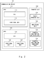
- Fig. 2 is a block diagram showing a detailed configuration of the first communication device 10 according to the example embodiment of the present invention.
- the second communication device 20 has the same configuration as that of the first communication device 10.
- the first communication device 10 includes a CPU 110, a CPU 120, and a transfer unit 130.
- the CPU 110 which is a computing device that performs various computations, implements an OS 111 and a functional unit 112.
- the OS 111 is a program for controlling the functional unit 112 that is implemented on the CPU 110.
- the functional unit 112 is another program for exerting one of functions of the first communication device 10, specifically, routes packets which are received from the external device.
- the CPU 120 which is another computing device that performs various computations, implements an OS 121 and functional units 122 and 123.
- the OS 121 is a program for controlling the functional units 122 and 123 that are implemented on the CPU 120.
- the functional unit 122 is another program for exerting another one of the functions of the first communication device 10, specifically, controls IP-telephone calls.
- the functional unit 123 is a still another program for exerting a still another one of the functions of the first communication device 10, specifically, controls IP-telephone audio communication.
- the transfer unit 130 is a semiconductor integrated device that processes the packets which are received from the external device.
- the transfer unit 130 includes a packet transfer unit 131, a monitoring unit 132, a transfer-destination switching unit 133, and a transfer-destination management table 134.
- the packet transfer unit 131 is a logic circuit that transfers the packets which are received from the external device. Specific examples of the packet transfer unit 131 includes an L2 switch.
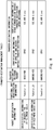
- Fig. 8 is a table showing an example of the transfer-destination management table 134. Packet identification information, functional-unit identification information, information which indicates whether or not a transfer-destination switching request has been made, and transfer-destination information are registered with the transfer-destination management table shown in Fig. 8 .
- the packet identification information is information for identifying the packets. Examples of the packet identification information to be registered include identification information that is unique to packets regarding the control of the IP-telephone calls, and identification information that is unique to packets regarding audio communication after establishment of connection to the IP telephone.
- the functional-unit identification information is identification information of the functional units of the first communication device 10 and the second communication device 20.
- the functional unit indicated by functional-unit identification information (function_a) is a functional unit that controls the IP-telephone calls
- the functional unit indicated by functional-unit identification information (function_b) is a functional unit that controls the IP-telephone audio communication.
- the functional unit indicated by functional-unit identification information (function_c) is a functional unit that routes data other than IP-telephone data. Note that the first communication device 10 and the second communication device 20 commonly use the functional-unit identification information.
- the information which indicates whether or not the transfer-destination switching request has been made is information which indicates whether or not the transfer-destination switching request has been received from another one of the communication devices. Information which indicates that the transfer-destination switching request has not been received is registered by default.
- the transfer-destination information is identification information of transfer destinations of the packets. As the transfer-destination information, identification information of the CPUs of an own device, and identification information (IP address) of the other one of the communication devices are used.
- the packet transfer unit 131 acquires the packet identification information from the packets which are received from the external device. Then, the packet transfer unit 131 refers to the transfer-destination management table 134, and specifies, out of the information items which indicate whether or not the transfer-destination switching request has been made, an information item that is associated with the packet identification information. Note that, if this packet identification information has not been registered with the transfer-destination management table 134, the packet transfer unit 131 specifies, out of the information items which indicate whether or not the transfer-destination switching request has been made, an information item that is associated with unregistered identification information (function_C in the example shown in Fig. 8 ).
- the packet transfer unit 131 specifies identification information of one of the CPUs of the own device, i.e., a default transfer destination, and then transfers the packets to the one of the CPUs. Meanwhile, if information which indicates that the transfer-destination switching request has been received is registered, that is, if the transfer-destination switching request has been received from the other one of the communication devices, the packet transfer unit 131 specifies the IP address of the other one of the communication devices, i.e., a transfer destination after switching, and then transfers the packets to the other one of the communication devices.
- the monitoring unit 132 is a logic circuit that determines whether or not the transfer-destination switching request has been received from the other one of the communication devices.
- the transfer-destination switching unit 133 is a logic circuit that switches, if the transfer-destination switching request is received from the other one of the communication devices, the transfer destination of packets that should be processed by a functional unit of a transmission origin of the transfer-destination switching request from a functional unit of the own device to the functional unit of the transmission origin of the transfer-destination switching request.
- the transfer-destination switching unit 133 registers information which indicates that the transfer-destination switching request has been made with the transfer-destination management table 134 on the basis of identification information of the functional unit of the transmission origin of the transfer-destination switching request, the identification information being included in the transfer-destination switching request.
- Fig. 3 is a block diagram showing a program module of each of the functional units of the first communication device 10 and the second communication device 20.
- the program module which is described hereinafter, is that of the functional unit 112 of the first communication device 10.
- Each of the other functional units of the first communication device 10 and the functional units of the second communication device 20 has the same program module as that of the functional unit 112 of the first communication device 10.
- the functional unit 112 includes a monitoring unit 300, a switching request unit 301, and a response unit 302.
- the monitoring unit 300 and the switching request unit 301 are implemented when the own device functions as a backup device, and the response unit 302 is implemented when the own device functions as a main device.
- the monitoring unit 300 is a program module that transmits a response request to a corresponding one of the functional units of the main device, the corresponding one corresponding to the functional unit 112 of the backup device, and that determines whether or not a response to the response request has been received from the corresponding one of the functional units of the main device.
- the switching request unit 301 is a program module that transmits, to the main device, the transfer-destination switching request for transferring the packets that should be processed by the functional unit 112 of the backup device to this functional unit 112 if the response to the response request has not been received from the corresponding one of the functional units of the main device, the corresponding one corresponding to the functional unit 112 of the backup device.
- the response unit 302 is a program module that determines whether or not the response request has been received from the backup device, and that transmits the response to the response request to the backup device if the response request has been received.
- Fig. 4 is a block diagram showing main components of each of the communication devices according to the example embodiment of the present invention.
- Each of the first communication device 10 and the second communication device 20 includes the functional unit 112 and the transfer unit 130 as its main components.
- the functional unit 112 includes the monitoring unit 300, the switching request unit 301, and the response unit 302.
- the transfer unit 130 includes the transfer-destination switching unit 133.
- Fig. 5 is a flowchart showing a procedure to be executed by each of the functional units of the second communication device 20 that functions as the backup device.
- the functional units of the first communication device 10 that functions as the main device are first functional units
- the functional units of the second communication device 20 that functions as the backup device are second functional units.
- one of the second functional units of the second communication device 20 transmits the response request to a corresponding one of the first functional units of the first communication device 10, the corresponding one of the first functional units corresponding to the one of the second functional units.
- the response request includes identification information of the response request, an IP address of the first communication device 10, i.e., a transmission destination of the response request, and identification information of the corresponding one of the first functional units.
- the packet transfer unit 131 of the transfer unit 130 of the first communication device 10 transfers the response request to the corresponding one of the first functional units, the corresponding one of the first functional units being indicated by the identification information of the corresponding one of the functional units.
- the packet transfer unit 131 transfers the packets to the functional unit 122 indicated by “function_A.” If the functional-unit identification information is "function_B,” the packet transfer unit 131 transfers the packets to the functional unit 123 indicated by “function_B.” If the functional-unit identification information is "function_C,” the packet transfer unit 131 transfers the packets to the functional unit 112 indicated by "function_C.”
- Step S102 the one of the second functional units determines whether or not to have received the response from the corresponding one of the first functional units of the first communication device 10. If the one of the second functional units has received the response (YES), the procedure returns to Step S101. Meanwhile, if the one of the second functional units has not received the response (NO), the procedure branches to Step S103. In Step S103, the one of the second functional units transmits the transfer-destination switching request to the transfer unit 130 of the first communication device 10. Then, the procedure shown in Fig. 5 is ended.
- the transfer-destination switching request includes identification information of the transfer-destination switching request, and identification information of the one of the second functional units, i.e., the transmission origin of the transfer-destination switching request, that is, the identification information of the corresponding one of the first functional units, the identification information of the corresponding one of the first functional units corresponding to the identification information of the one of the second functional units.
- the transfer-destination switching unit 133 of the transfer unit 130 of the first communication device 10 updates the transfer-destination management table 134 so that the transfer destination of the packets that should be processed by the one of the second functional units is switched from the corresponding one of the first functional units to the one of the second functional units.
- Fig. 6 is a flowchart showing a procedure to be executed by each of the functional units of the first communication device 10 that functions as the main device.
- Step S201 the corresponding one of the first functional units of the first communication device 10 determines whether or not to have received the response request from the one of the second functional units of the second communication device 20 via the transfer unit 130, the one of the second functional units corresponding to the corresponding one of the first functional units. If the corresponding one of the first functional units has not received the response request (NO), the process of Step S201 is executed again. Meanwhile, if the corresponding one of the first functional units has received the response request (YES), the procedure branches to Step S202. In Step S202, the corresponding one of the first functional units transmits the response to the one of the second functional units of the second communication device 20, i.e., the transmission origin of the response request. Then, the procedure shown in Fig. 6 is ended.
- Fig. 7 is a flowchart showing a procedure to be executed by the transfer unit 130 of the first communication device 10 that functions as the main device.
- the monitoring unit 132 of the transfer unit 130 determines whether or not the transfer-destination switching request has been received from the second communication device 20. If the transfer-destination switching request has not been received (NO), the process of Step S301 is executed again. Meanwhile, if the transfer-destination switching request has been received (YES), the procedure branches to Step S302.
- Step S302 the transfer-destination switching unit 133 of the transfer unit 130 updates the transfer-destination management table 134 so as to switch the transfer destination of the packets that should be processed by the one of the functional units of the transmission origin of the transfer-destination switching request to this one of the functional units. Then, the procedure shown in Fig. 7 is ended. Specifically, the transfer-destination switching unit 133 refers to the transfer-destination management table 134, and registers information, which indicates that the transfer-destination switching request has been made, in association with the identification information of the one of the functional units of the transmission origin of the transfer-destination switching request, the identification information being included in the transfer-destination switching request. By doing so, if the packets that should be processed by the one of the functional units of the transmission origin of the transfer-destination switching request are received, the packet transfer unit 131 transfers these packets to this one of the functional units.
- the second functional units of the second communication device 20 transmit response requests respectively to the corresponding first functional units. By doing so, keep-alive monitoring on each of the functional units is performed. Then, if there is no response to the response request, one of the second functional units causes the transfer unit 130 of the first communication device 10 to switch a transfer destination of packets that are supposed to be processed by a corresponding one of the first functional units to the one of the second functional units, the corresponding one of the first functional units having not transmitted the response. Subsequently, the one of the second functional units of the second communication device 20 processes the packets. By doing so, in case where a problem occurs only to a certain one functional unit of a plurality of functional units of a communication device, a function of this functional unit can be independently exerted by another communication device.
- the transfer-destination switching unit 133 of the first communication device 10 switches the transfer destination of the packets that are supposed to be processed by the corresponding one of the first functional units from the corresponding one of the first functional units to the one of the second functional units, the corresponding one having not transmitted the response.
- the transfer-destination switching unit 133 of the first communication device 10 does not switch transfer destinations of other packets.
- other ones of the functional units, to which problems have not occurred can continue to process the packets. In this way, data loss or temporary outage that may occur in switching the functional units that process the packets can be prevented.
- the programs are stored by using non-transitory computer-readable media of various types, and can be provided to computers.
- the non-transitory computer-readable media encompass tangible storage media of various types. Examples of the non-transitory computer-readable media include magnetic storage media (such as a flexible disk, a magnetic tape, and a hard disk drive), magneto-optical storage media (such as a magneto-optical disk), a CD-ROM, a CD-R, a CD-R/W, and semiconductor memories (such as a mask ROM, a PROM (Programmable ROM), an EPROM (Erasable PROM), a flash ROM, and a RAM).
- the programs may be provided to the computers via transitory computer-readable media of various types.
- transitory computer-readable media include an electrical signal, an optical signal, and an electromagnetic wave. These transitory computer-readable media are able to supply the programs to the computers through wired communication paths such as an electric wire and optical fiber or a wireless communication path.
- the present invention is not limited to the foregoing example embodiment, and modifications may be made as appropriate within the gist of the present invention.
- the CPU 110 and the CPU 120 respectively implement the one functional unit and the two functional units in the above description of this example embodiment, each of the CPU 110 and the CPU 120 may implement an arbitrary number of functional units in another example embodiment.
- the CPU 110 and the CPU 120 may implement functional units that execute various other processes than these processes (such as an application that performs WAN communication).
Landscapes
- Engineering & Computer Science (AREA)
- Computer Networks & Wireless Communication (AREA)
- Signal Processing (AREA)
- Data Exchanges In Wide-Area Networks (AREA)
- Small-Scale Networks (AREA)
Abstract
Description
- The present invention relates to a communication system and a communication device. More specifically, the present invention relates to a communication system and a communication device that enables fault tolerance.
- Hitherto, in IP (Internet Protocol) telephone systems, a communication device having a plurality of functions such as a routing function, a call control function, and an audio-communication control function has been used. Generally, such a communication device includes a single CPU (Central Processing Unit), and this CPU executes a routing process, a call control process, and an audio-communication control process. In this way, the routing function, the call control function, and the audio-communication control function are exerted. However, in case where a failure occurs to the CPU, or in case where a problem occurs to an OS (Operating System) or a functional unit that is implemented by the communication device, terminal devices that use the communication device cannot perform data communication via the communication device.
- As a countermeasure against this problem, the IP telephone system disclosed in Patent Literature 1 employs redundancy with use of a plurality of IP telephones. Specifically, an extension control function is assigned to one of IP telephones, and another one of the IP telephones functions, i.e., a backup terminal operates as an extension control terminal in case where a failure occurs to the one of the IP telephone terminals. In this way, even in case where a failure occurs to one of the IP telephone terminals, a function of the audio communication via the IP telephones is continuously provided.
-
Japanese Patent No. 5218626 - However, the IP telephone system disclosed in Patent Literature 1 has a disadvantage that, in case where a problem occurs only to a certain one functional unit of a plurality of functional units of a device, a function of this functional unit cannot be independently exerted by another device.
- The present invention has been made in view of the problem as described above, and an object of the present invention is to provide a communication system and a communication device that enable a function of a certain one functional unit of a plurality of functional units of a communication device to be independently exerted by another communication device in case where a problem occurs only to the certain one functional unit.
- According to the present invention, there is provided a communication system including:
- a first communication device that includes a first functional unit and a first transfer unit, and that functions as a main device; and
- a second communication device that includes a second functional unit and a second transfer unit, and that functions as a backup device for the first communication device.
- The second functional unit includes
- a monitoring unit configured to transmit a response request to the first functional unit, and configured to determine whether or not a response to the response request has been received from the first functional unit, and
- a switching request unit configured to transmit, to the first communication device, a transfer-destination switching request for transferring packets that should be processed by the second functional unit to the second functional unit if the response has not been received from the first functional unit.
- The first functional unit includes a response unit configured to determine whether or not the response request has been received from the second functional unit, and configured to transmit the response to the second functional unit if the response request has been received from the second functional unit.
- The first transfer unit includes a transfer-destination switching unit configured to switch a transfer destination of the packets that should be processed by the second functional unit from the first functional unit to the second functional unit if the transfer-destination switching request has been received from the second functional unit.
- According to the present invention, it is possible to provide the communication system and the communication device that enable a function of a certain one functional unit of a plurality of functional units of a communication device to be independently exerted by another communication device in case where a problem occurs only to the certain one functional unit.
-
-
Fig. 1 is a schematic diagram showing a communication system according to an example embodiment of the present invention; -
Fig. 2 is a block diagram showing a detailed configuration of a communication device according to the example embodiment of the present invention; -
Fig. 3 is a block diagram showing a detailed configuration of a functional unit of the communication device according to the example embodiment of the present invention; -
Fig. 4 is a block diagram showing a schematic configuration of each of the communication devices according to the example embodiment of the present invention; -
Fig. 5 is a flowchart showing a procedure to be executed by a second communication device that functions as a backup device; -
Fig. 6 is a flowchart showing a procedure to be executed by a first communication device that functions as a main device; -
Fig. 7 is a flowchart showing another procedure to be executed by the first communication device that functions as the main device; and -
Fig. 8 is a table showing an example of a transfer-destination management table. - An example embodiment of the present invention is described hereinafter with reference to the drawings.
Fig. 1 is a schematic diagram showing acommunication system 50 according to the example embodiment of the present invention. Thecommunication system 50 includes afirst communication device 10, asecond communication device 20, andterminal devices first communication device 10 and thesecond communication device 20 include a router that functions as an access point. Thefirst communication device 10 and thesecond communication device 20 are able to perform data communication with each other through a communication cable. In addition, thefirst communication device 10 and thesecond communication device 20 are connected to a WAN (Wide Area Network) such as the Internet 40 so that data communication with an external device can be performed. Thefirst communication device 10 and theterminal devices first communication device 10 and thesecond communication device 20 are able to implement a VRRP (Virtual Router Redundancy Protocol). This enables theterminal devices terminal devices first communication device 10 inFig. 1 , a single communication device or three or more communication devices may be connected thereto. In addition, thefirst communication device 10 and thesecond communication device 20 may perform the data communication with each other via a wireless LAN. -
Fig. 2 is a block diagram showing a detailed configuration of thefirst communication device 10 according to the example embodiment of the present invention. With regard to the following description of the configuration of thefirst communication device 10, thesecond communication device 20 has the same configuration as that of thefirst communication device 10. Thefirst communication device 10 includes aCPU 110, aCPU 120, and atransfer unit 130. - The
CPU 110, which is a computing device that performs various computations, implements anOS 111 and afunctional unit 112. The OS 111 is a program for controlling thefunctional unit 112 that is implemented on theCPU 110. Thefunctional unit 112 is another program for exerting one of functions of thefirst communication device 10, specifically, routes packets which are received from the external device. - The
CPU 120, which is another computing device that performs various computations, implements anOS 121 andfunctional units functional units CPU 120. Thefunctional unit 122 is another program for exerting another one of the functions of thefirst communication device 10, specifically, controls IP-telephone calls. Thefunctional unit 123 is a still another program for exerting a still another one of the functions of thefirst communication device 10, specifically, controls IP-telephone audio communication. - The
transfer unit 130 is a semiconductor integrated device that processes the packets which are received from the external device. Thetransfer unit 130 includes apacket transfer unit 131, amonitoring unit 132, a transfer-destination switching unit 133, and a transfer-destination management table 134. - The
packet transfer unit 131 is a logic circuit that transfers the packets which are received from the external device. Specific examples of thepacket transfer unit 131 includes an L2 switch.Fig. 8 is a table showing an example of the transfer-destination management table 134. Packet identification information, functional-unit identification information, information which indicates whether or not a transfer-destination switching request has been made, and transfer-destination information are registered with the transfer-destination management table shown inFig. 8 . The packet identification information is information for identifying the packets. Examples of the packet identification information to be registered include identification information that is unique to packets regarding the control of the IP-telephone calls, and identification information that is unique to packets regarding audio communication after establishment of connection to the IP telephone. - The functional-unit identification information is identification information of the functional units of the
first communication device 10 and thesecond communication device 20. In the example shown inFig. 8 , the functional unit indicated by functional-unit identification information (function_a) is a functional unit that controls the IP-telephone calls, and the functional unit indicated by functional-unit identification information (function_b) is a functional unit that controls the IP-telephone audio communication. In addition, the functional unit indicated by functional-unit identification information (function_c) is a functional unit that routes data other than IP-telephone data. Note that thefirst communication device 10 and thesecond communication device 20 commonly use the functional-unit identification information. - The information which indicates whether or not the transfer-destination switching request has been made is information which indicates whether or not the transfer-destination switching request has been received from another one of the communication devices. Information which indicates that the transfer-destination switching request has not been received is registered by default. The transfer-destination information is identification information of transfer destinations of the packets. As the transfer-destination information, identification information of the CPUs of an own device, and identification information (IP address) of the other one of the communication devices are used.
- The
packet transfer unit 131 acquires the packet identification information from the packets which are received from the external device. Then, thepacket transfer unit 131 refers to the transfer-destination management table 134, and specifies, out of the information items which indicate whether or not the transfer-destination switching request has been made, an information item that is associated with the packet identification information. Note that, if this packet identification information has not been registered with the transfer-destination management table 134, thepacket transfer unit 131 specifies, out of the information items which indicate whether or not the transfer-destination switching request has been made, an information item that is associated with unregistered identification information (function_C in the example shown inFig. 8 ). If the information which indicates that the transfer-destination switching request has not been received is registered, that is, if the transfer-destination switching request has not been received from the other one of the communication devices, thepacket transfer unit 131 specifies identification information of one of the CPUs of the own device, i.e., a default transfer destination, and then transfers the packets to the one of the CPUs. Meanwhile, if information which indicates that the transfer-destination switching request has been received is registered, that is, if the transfer-destination switching request has been received from the other one of the communication devices, thepacket transfer unit 131 specifies the IP address of the other one of the communication devices, i.e., a transfer destination after switching, and then transfers the packets to the other one of the communication devices. - The
monitoring unit 132 is a logic circuit that determines whether or not the transfer-destination switching request has been received from the other one of the communication devices. The transfer-destination switching unit 133 is a logic circuit that switches, if the transfer-destination switching request is received from the other one of the communication devices, the transfer destination of packets that should be processed by a functional unit of a transmission origin of the transfer-destination switching request from a functional unit of the own device to the functional unit of the transmission origin of the transfer-destination switching request. Specifically, if themonitoring unit 132 determines that the transfer-destination switching request has been received from the other one of the communication devices, the transfer-destination switching unit 133 registers information which indicates that the transfer-destination switching request has been made with the transfer-destination management table 134 on the basis of identification information of the functional unit of the transmission origin of the transfer-destination switching request, the identification information being included in the transfer-destination switching request. -
Fig. 3 is a block diagram showing a program module of each of the functional units of thefirst communication device 10 and thesecond communication device 20. The program module, which is described hereinafter, is that of thefunctional unit 112 of thefirst communication device 10. Each of the other functional units of thefirst communication device 10 and the functional units of thesecond communication device 20 has the same program module as that of thefunctional unit 112 of thefirst communication device 10. - The
functional unit 112 includes amonitoring unit 300, aswitching request unit 301, and aresponse unit 302. Themonitoring unit 300 and theswitching request unit 301 are implemented when the own device functions as a backup device, and theresponse unit 302 is implemented when the own device functions as a main device. - The
monitoring unit 300 is a program module that transmits a response request to a corresponding one of the functional units of the main device, the corresponding one corresponding to thefunctional unit 112 of the backup device, and that determines whether or not a response to the response request has been received from the corresponding one of the functional units of the main device. - The switching
request unit 301 is a program module that transmits, to the main device, the transfer-destination switching request for transferring the packets that should be processed by thefunctional unit 112 of the backup device to thisfunctional unit 112 if the response to the response request has not been received from the corresponding one of the functional units of the main device, the corresponding one corresponding to thefunctional unit 112 of the backup device. - The
response unit 302 is a program module that determines whether or not the response request has been received from the backup device, and that transmits the response to the response request to the backup device if the response request has been received. -
Fig. 4 is a block diagram showing main components of each of the communication devices according to the example embodiment of the present invention. Each of thefirst communication device 10 and thesecond communication device 20 includes thefunctional unit 112 and thetransfer unit 130 as its main components. Thefunctional unit 112 includes themonitoring unit 300, the switchingrequest unit 301, and theresponse unit 302. Thetransfer unit 130 includes the transfer-destination switching unit 133. -
Fig. 5 is a flowchart showing a procedure to be executed by each of the functional units of thesecond communication device 20 that functions as the backup device. In the following description, the functional units of thefirst communication device 10 that functions as the main device are first functional units, and the functional units of thesecond communication device 20 that functions as the backup device are second functional units. - In Step S101, one of the second functional units of the
second communication device 20 transmits the response request to a corresponding one of the first functional units of thefirst communication device 10, the corresponding one of the first functional units corresponding to the one of the second functional units. The response request includes identification information of the response request, an IP address of thefirst communication device 10, i.e., a transmission destination of the response request, and identification information of the corresponding one of the first functional units. When the response request has been received from thesecond communication device 20, thepacket transfer unit 131 of thetransfer unit 130 of thefirst communication device 10 transfers the response request to the corresponding one of the first functional units, the corresponding one of the first functional units being indicated by the identification information of the corresponding one of the functional units. For example, in the example embodiment in which the functional-unit identification information shown inFig. 8 is used, if the functional-unit identification information is "function_A," thepacket transfer unit 131 transfers the packets to thefunctional unit 122 indicated by "function_A." If the functional-unit identification information is "function_B," thepacket transfer unit 131 transfers the packets to thefunctional unit 123 indicated by "function_B." If the functional-unit identification information is "function_C," thepacket transfer unit 131 transfers the packets to thefunctional unit 112 indicated by "function_C." - In Step S102, the one of the second functional units determines whether or not to have received the response from the corresponding one of the first functional units of the
first communication device 10. If the one of the second functional units has received the response (YES), the procedure returns to Step S101. Meanwhile, if the one of the second functional units has not received the response (NO), the procedure branches to Step S103. In Step S103, the one of the second functional units transmits the transfer-destination switching request to thetransfer unit 130 of thefirst communication device 10. Then, the procedure shown inFig. 5 is ended. The transfer-destination switching request includes identification information of the transfer-destination switching request, and identification information of the one of the second functional units, i.e., the transmission origin of the transfer-destination switching request, that is, the identification information of the corresponding one of the first functional units, the identification information of the corresponding one of the first functional units corresponding to the identification information of the one of the second functional units. As will be described in detail with reference toFig. 7 , the transfer-destination switching unit 133 of thetransfer unit 130 of thefirst communication device 10 updates the transfer-destination management table 134 so that the transfer destination of the packets that should be processed by the one of the second functional units is switched from the corresponding one of the first functional units to the one of the second functional units. -
Fig. 6 is a flowchart showing a procedure to be executed by each of the functional units of thefirst communication device 10 that functions as the main device. In Step S201, the corresponding one of the first functional units of thefirst communication device 10 determines whether or not to have received the response request from the one of the second functional units of thesecond communication device 20 via thetransfer unit 130, the one of the second functional units corresponding to the corresponding one of the first functional units. If the corresponding one of the first functional units has not received the response request (NO), the process of Step S201 is executed again. Meanwhile, if the corresponding one of the first functional units has received the response request (YES), the procedure branches to Step S202. In Step S202, the corresponding one of the first functional units transmits the response to the one of the second functional units of thesecond communication device 20, i.e., the transmission origin of the response request. Then, the procedure shown inFig. 6 is ended. -
Fig. 7 is a flowchart showing a procedure to be executed by thetransfer unit 130 of thefirst communication device 10 that functions as the main device. In Step S301, themonitoring unit 132 of thetransfer unit 130 determines whether or not the transfer-destination switching request has been received from thesecond communication device 20. If the transfer-destination switching request has not been received (NO), the process of Step S301 is executed again. Meanwhile, if the transfer-destination switching request has been received (YES), the procedure branches to Step S302. In Step S302, the transfer-destination switching unit 133 of thetransfer unit 130 updates the transfer-destination management table 134 so as to switch the transfer destination of the packets that should be processed by the one of the functional units of the transmission origin of the transfer-destination switching request to this one of the functional units. Then, the procedure shown inFig. 7 is ended. Specifically, the transfer-destination switching unit 133 refers to the transfer-destination management table 134, and registers information, which indicates that the transfer-destination switching request has been made, in association with the identification information of the one of the functional units of the transmission origin of the transfer-destination switching request, the identification information being included in the transfer-destination switching request. By doing so, if the packets that should be processed by the one of the functional units of the transmission origin of the transfer-destination switching request are received, thepacket transfer unit 131 transfers these packets to this one of the functional units. - In the above description of this example embodiment, the second functional units of the
second communication device 20, i.e., the backup device, transmit response requests respectively to the corresponding first functional units. By doing so, keep-alive monitoring on each of the functional units is performed. Then, if there is no response to the response request, one of the second functional units causes thetransfer unit 130 of thefirst communication device 10 to switch a transfer destination of packets that are supposed to be processed by a corresponding one of the first functional units to the one of the second functional units, the corresponding one of the first functional units having not transmitted the response. Subsequently, the one of the second functional units of thesecond communication device 20 processes the packets. By doing so, in case where a problem occurs only to a certain one functional unit of a plurality of functional units of a communication device, a function of this functional unit can be independently exerted by another communication device. - In addition, in the above description of this example embodiment, if the transfer-destination switching request has been received from the
second communication device 20, the transfer-destination switching unit 133 of thefirst communication device 10 switches the transfer destination of the packets that are supposed to be processed by the corresponding one of the first functional units from the corresponding one of the first functional units to the one of the second functional units, the corresponding one having not transmitted the response. In addition, the transfer-destination switching unit 133 of thefirst communication device 10 does not switch transfer destinations of other packets. Thus, even in case where a problem occurs to a certain one of the functional units, other ones of the functional units, to which problems have not occurred, can continue to process the packets. In this way, data loss or temporary outage that may occur in switching the functional units that process the packets can be prevented. - In the above-described examples, the programs are stored by using non-transitory computer-readable media of various types, and can be provided to computers. The non-transitory computer-readable media encompass tangible storage media of various types. Examples of the non-transitory computer-readable media include magnetic storage media (such as a flexible disk, a magnetic tape, and a hard disk drive), magneto-optical storage media (such as a magneto-optical disk), a CD-ROM, a CD-R, a CD-R/W, and semiconductor memories (such as a mask ROM, a PROM (Programmable ROM), an EPROM (Erasable PROM), a flash ROM, and a RAM). In addition, the programs may be provided to the computers via transitory computer-readable media of various types. Examples of these transitory computer-readable media include an electrical signal, an optical signal, and an electromagnetic wave. These transitory computer-readable media are able to supply the programs to the computers through wired communication paths such as an electric wire and optical fiber or a wireless communication path.
- The present invention is not limited to the foregoing example embodiment, and modifications may be made as appropriate within the gist of the present invention. For example, although the
CPU 110 and theCPU 120 respectively implement the one functional unit and the two functional units in the above description of this example embodiment, each of theCPU 110 and theCPU 120 may implement an arbitrary number of functional units in another example embodiment. In addition, with regard to the functional unit that routes the packets and the functional units that execute the processes for the IP telephone in the above description of this example embodiment, theCPU 110 and theCPU 120 may implement functional units that execute various other processes than these processes (such as an application that performs WAN communication). - This application claims the benefit of
Japanese Patent Application No. 2018-240552 filed on December 25, 2018 -
- 10
- FIRST COMMUNICATION DEVICE
- 20
- SECOND COMMUNICATION DEVICE
- 30a
- TERMINAL DEVICE
- 30b
- TERMINAL DEVICE
- 40
- INTERNET
- 50
- COMMUNICATION SYSTEM
Claims (10)
- A communication system comprising:a first communication device that includes a first functional unit and a first transfer unit, and that functions as a main device; anda second communication device that includes a second functional unit and a second transfer unit, and that functions as a backup device for the first communication device, whereinthe second functional unit includesa monitoring unit configured to transmit a response request to the first functional unit, and configured to determine whether or not a response to the response request has been received from the first functional unit, anda switching request unit configured to transmit, to the first communication device, a transfer-destination switching request for transferring packets that should be processed by the second functional unit to the second functional unit if the response has not been received from the first functional unit,the first functional unit includes a response unit configured to determine whether or not the response request has been received from the second functional unit, and configured to transmit the response to the second functional unit if the response request has been received from the second functional unit, andthe first transfer unit includes a transfer-destination switching unit configured to switch a transfer destination of the packets that should be processed by the second functional unit from the first functional unit to the second functional unit if the transfer-destination switching request has been received from the second functional unit.
- The communication system according to Claim 1, whereinthe first communication device includes a plurality of computing devices and a plurality of the first functional units,the second communication device includes a plurality of computing devices and a plurality of second functional units,at least some units of the plurality of the first functional units are implemented on different devices of the plurality of the computing devices of the first communication device, andat least some units of the plurality of the second functional units are implemented on different devices of the plurality of the computing devices of the second communication device.
- The communication system according to Claim 1 or 2, wherein if the transfer-destination switching request has been received from the second communication device, the transfer-destination switching unit of the first communication device switches the transfer destination of the packets that should be processed by the second functional unit from the first functional unit to the second functional unit, the second functional unit being a transmission origin of the transfer-destination switching request, and the transfer-destination switching unit of the first communication device does not switch transfer destinations of other packets.
- The communication system according to any one of Claims 1 to 3, wherein if the response has not been received from the first functional unit due to a problem that has occurred to the first functional unit, the switching request unit of the second communication device transmits the transfer-destination switching request to the first communication device.
- A communication device that functions as a backup device comprising a second functional unit includinga monitoring unit configured to transmit a response request to a first functional unit of another communication device, and configured to determine whether or not a response to the response request has been received from the first functional unit of the another communication device, anda switching request unit configured to transmit, to the another communication device, a transfer-destination switching request for transferring packets that should be processed by an own device to the own device if the response has not been received from the first functional unit of the another communication device.
- The communication device according to Claim 5, further comprising a plurality of computing devices and a plurality of the second functional units, wherein
at least some units of the plurality of the second functional units are implemented on different devices of the plurality of the computing devices. - The communication device according to Claim 5 or 6, wherein if the response has not been received from the first functional unit of the another communication device due to a problem that has occurred to the first functional unit of the another communication device, the switching request unit transmits the transfer-destination switching request to the another communication device.
- A communication device that functions as a main device comprising:a first functional unit including a response unit configured to determine whether or not a response request has been received from another communication device, and configured to transmit a response to the response request to the another communication device if the response request has been received from the another communication device; anda transfer-destination switching unit configured to switch a transfer destination of packets that should be processed by a second functional unit of the another communication device from the first functional unit to the second functional unit if a transfer-destination switching request has been received from the another communication device.
- The communication device according to Claim 8, further comprising a plurality of computing devices and a plurality of the first functional units, wherein
at least some units of the plurality of the first functional units are implemented on different devices of the plurality of the computing devices. - The communication device according to Claim 8 or 9, wherein if the transfer-destination switching request has been received from the another communication device, the transfer-destination switching unit switches the transfer destination of the packets that should be processed by the second functional unit from the first functional unit to the second functional unit of the another communication device, the second functional unit being a transmission origin of the transfer-destination switching request, and the transfer-destination switching unit does not switch transfer destinations of other packets.
Applications Claiming Priority (2)
| Application Number | Priority Date | Filing Date | Title |
|---|---|---|---|
| JP2018240552A JP6791538B2 (en) | 2018-12-25 | 2018-12-25 | Communication system and communication equipment |
| PCT/JP2019/048786 WO2020137597A1 (en) | 2018-12-25 | 2019-12-12 | Communication system and communication device |
Publications (4)
| Publication Number | Publication Date |
|---|---|
| EP3886370A1 true EP3886370A1 (en) | 2021-09-29 |
| EP3886370A4 EP3886370A4 (en) | 2022-01-26 |
| EP3886370B1 EP3886370B1 (en) | 2024-03-06 |
| EP3886370C0 EP3886370C0 (en) | 2024-03-06 |
Family
ID=71126304
Family Applications (1)
| Application Number | Title | Priority Date | Filing Date |
|---|---|---|---|
| EP19902958.8A Active EP3886370B1 (en) | 2018-12-25 | 2019-12-12 | Communication system and communication device |
Country Status (7)
| Country | Link |
|---|---|
| US (1) | US11722362B2 (en) |
| EP (1) | EP3886370B1 (en) |
| JP (1) | JP6791538B2 (en) |
| CN (1) | CN113228566B (en) |
| AU (1) | AU2019411787B2 (en) |
| CA (1) | CA3125083C (en) |
| WO (1) | WO2020137597A1 (en) |
Families Citing this family (1)
| Publication number | Priority date | Publication date | Assignee | Title |
|---|---|---|---|---|
| CN115766411B (en) * | 2022-11-15 | 2025-05-13 | 国电南瑞科技股份有限公司 | A method for accurately determining and switching the status of two machines in a multiplexed process bus |
Family Cites Families (13)
| Publication number | Priority date | Publication date | Assignee | Title |
|---|---|---|---|---|
| US7103002B2 (en) * | 2000-07-12 | 2006-09-05 | Telefonktiebolaget Lm Ericsson (Publ) | Communication management in networks having split control planes and user planes |
| ES2275008T3 (en) * | 2001-09-14 | 2007-06-01 | Siemens Aktiengesellschaft | COMMUNICATIONS PROCEDURE AND TEAM TO MAKE AT LEAST A RELATIONSHIP OF SAFE COMMUNICATION |
| EP1676425B1 (en) * | 2003-10-09 | 2010-12-08 | Telecom Italia S.p.A. | Method and system for fault protection in a communication network |
| US8930036B2 (en) * | 2011-04-13 | 2015-01-06 | GM Global Technology Operations LLC | Reconfigurable interface-based electrical architecture |
| JP5218626B2 (en) | 2011-11-17 | 2013-06-26 | 株式会社ナカヨ通信機 | IP telephone system and IP telephone terminal |
| US9747183B2 (en) * | 2013-12-31 | 2017-08-29 | Ciena Corporation | Method and system for intelligent distributed health monitoring in switching system equipment |
| CN103713932B (en) | 2014-01-21 | 2017-03-08 | 北京经纬恒润科技有限公司 | The update method of application program and device in a kind of electronic control unit |
| CN107005580B (en) * | 2014-11-04 | 2020-08-18 | 瑞典爱立信有限公司 | Methods and associated manager nodes for managing service sets |
| JP6472312B2 (en) * | 2015-04-15 | 2019-02-20 | 株式会社Nttドコモ | Functional part assignment apparatus and functional part assignment method |
| WO2018180613A1 (en) | 2017-03-29 | 2018-10-04 | 日本電気株式会社 | Virtual network system, vim, virtual network control method and recording medium |
| US10411948B2 (en) * | 2017-08-14 | 2019-09-10 | Nicira, Inc. | Cooperative active-standby failover between network systems |
| US10673957B2 (en) * | 2018-06-28 | 2020-06-02 | At&T Intellectual Property I, L.P. | Providing high availability in a software defined network |
| JP7132494B2 (en) * | 2018-08-21 | 2022-09-07 | 富士通株式会社 | Multi-cloud operation program and multi-cloud operation method |
-
2018
- 2018-12-25 JP JP2018240552A patent/JP6791538B2/en active Active
-
2019
- 2019-12-12 US US17/311,758 patent/US11722362B2/en active Active
- 2019-12-12 CN CN201980085772.0A patent/CN113228566B/en active Active
- 2019-12-12 CA CA3125083A patent/CA3125083C/en active Active
- 2019-12-12 EP EP19902958.8A patent/EP3886370B1/en active Active
- 2019-12-12 AU AU2019411787A patent/AU2019411787B2/en active Active
- 2019-12-12 WO PCT/JP2019/048786 patent/WO2020137597A1/en not_active Ceased
Also Published As
| Publication number | Publication date |
|---|---|
| EP3886370B1 (en) | 2024-03-06 |
| US11722362B2 (en) | 2023-08-08 |
| CA3125083A1 (en) | 2020-07-02 |
| US20220029878A1 (en) | 2022-01-27 |
| JP2020102799A (en) | 2020-07-02 |
| CN113228566A (en) | 2021-08-06 |
| WO2020137597A1 (en) | 2020-07-02 |
| EP3886370C0 (en) | 2024-03-06 |
| AU2019411787A1 (en) | 2021-06-24 |
| CN113228566B (en) | 2023-07-25 |
| JP6791538B2 (en) | 2020-11-25 |
| AU2019411787B2 (en) | 2024-08-01 |
| EP3886370A4 (en) | 2022-01-26 |
| CA3125083C (en) | 2023-09-05 |
Similar Documents
| Publication | Publication Date | Title |
|---|---|---|
| US9455916B2 (en) | Method and system for changing path and controller thereof | |
| US20140022894A1 (en) | Network system, switch and connected terminal detection method | |
| US10454817B2 (en) | Method and device for processing GR of openflow switch, and openflow controller | |
| WO2018108149A1 (en) | Data-link switching method and apparatus and data-link switching device | |
| CN111130943B (en) | Method for realizing fast ring network switching, switch and computer readable storage medium | |
| US9451483B2 (en) | Mobile communication system, communication system, control node, call-processing node, and communication control method | |
| CN109889411B (en) | Data transmission method and device | |
| JP5402688B2 (en) | Packet transfer system and method for avoiding packet concentration in packet transfer system | |
| EP3886370B1 (en) | Communication system and communication device | |
| EP2830266A1 (en) | Communication system, control device, communication device, information-relaying method, and program | |
| CN108337162B (en) | System and method for supporting dual-homing protection | |
| CN112887201A (en) | VRRP (virtual router redundancy protocol) -based interface updating method and device and storage medium | |
| JP2011188623A (en) | Safety control system | |
| KR101576518B1 (en) | Method and apparatus for expansion and utilization of openflow protocol | |
| JP2015106865A (en) | Communication device, communication system, communication method, and communication program | |
| JP2003345478A (en) | Intelligent type device where all intelligent type modules can share the same user input / output interface | |
| US20160197817A1 (en) | Network system, control device, control method, and non-transitory computer-readable medium | |
| JP2009246475A (en) | Communication system with redundancy composition, and system switching method of the system | |
| CA2630125C (en) | Slot interface access device and slot interface access method | |
| CN113839858A (en) | Communication method and communication device | |
| CN105306358A (en) | Main and spare routing equipment, backup and switch method between equipment and routing system | |
| JP2010218304A (en) | Communication control apparatus, data synchronization method and program for data synchronization | |
| JP2025037666A (en) | PUSH NOTIFICATION PROCESSING DEVICE, PUSH NOTIFICATION PROCESSING SYSTEM, AND PUSH NOTIFICATION PROCESSING METHOD | |
| CN117793944A (en) | Communication method, network and system, session management function network element and storage medium | |
| CN103414590B (en) | A kind of method for upgrading software and equipment |
Legal Events
| Date | Code | Title | Description |
|---|---|---|---|
| STAA | Information on the status of an ep patent application or granted ep patent |
Free format text: STATUS: THE INTERNATIONAL PUBLICATION HAS BEEN MADE |
|
| PUAI | Public reference made under article 153(3) epc to a published international application that has entered the european phase |
Free format text: ORIGINAL CODE: 0009012 |
|
| STAA | Information on the status of an ep patent application or granted ep patent |
Free format text: STATUS: REQUEST FOR EXAMINATION WAS MADE |
|
| 17P | Request for examination filed |
Effective date: 20210624 |
|
| AK | Designated contracting states |
Kind code of ref document: A1 Designated state(s): AL AT BE BG CH CY CZ DE DK EE ES FI FR GB GR HR HU IE IS IT LI LT LU LV MC MK MT NL NO PL PT RO RS SE SI SK SM TR |
|
| STAA | Information on the status of an ep patent application or granted ep patent |
Free format text: STATUS: EXAMINATION IS IN PROGRESS |
|
| A4 | Supplementary search report drawn up and despatched |
Effective date: 20220104 |
|
| RIC1 | Information provided on ipc code assigned before grant |
Ipc: H04L 12/40 20060101ALI20211221BHEP Ipc: H04L 12/24 20060101AFI20211221BHEP |
|
| 17Q | First examination report despatched |
Effective date: 20220114 |
|
| DAV | Request for validation of the european patent (deleted) | ||
| DAX | Request for extension of the european patent (deleted) | ||
| REG | Reference to a national code |
Ref country code: DE Ref legal event code: R079 Free format text: PREVIOUS MAIN CLASS: H04L0012280000 Ipc: H04L0041066300 Ref document number: 602019048022 Country of ref document: DE |
|
| GRAP | Despatch of communication of intention to grant a patent |
Free format text: ORIGINAL CODE: EPIDOSNIGR1 |
|
| STAA | Information on the status of an ep patent application or granted ep patent |
Free format text: STATUS: GRANT OF PATENT IS INTENDED |
|
| RIC1 | Information provided on ipc code assigned before grant |
Ipc: H04L 12/40 20060101ALI20231018BHEP Ipc: H04L 41/0663 20220101AFI20231018BHEP |
|
| INTG | Intention to grant announced |
Effective date: 20231031 |
|
| GRAS | Grant fee paid |
Free format text: ORIGINAL CODE: EPIDOSNIGR3 |
|
| GRAA | (expected) grant |
Free format text: ORIGINAL CODE: 0009210 |
|
| STAA | Information on the status of an ep patent application or granted ep patent |
Free format text: STATUS: THE PATENT HAS BEEN GRANTED |
|
| AK | Designated contracting states |
Kind code of ref document: B1 Designated state(s): AL AT BE BG CH CY CZ DE DK EE ES FI FR GB GR HR HU IE IS IT LI LT LU LV MC MK MT NL NO PL PT RO RS SE SI SK SM TR |
|
| REG | Reference to a national code |
Ref country code: CH Ref legal event code: EP |
|
| REG | Reference to a national code |
Ref country code: IE Ref legal event code: FG4D |
|
| REG | Reference to a national code |
Ref country code: DE Ref legal event code: R096 Ref document number: 602019048022 Country of ref document: DE |
|
| U01 | Request for unitary effect filed |
Effective date: 20240321 |
|
| U07 | Unitary effect registered |
Designated state(s): AT BE BG DE DK EE FI FR IT LT LU LV MT NL PT SE SI Effective date: 20240402 |
|
| PG25 | Lapsed in a contracting state [announced via postgrant information from national office to epo] |
Ref country code: GR Free format text: LAPSE BECAUSE OF FAILURE TO SUBMIT A TRANSLATION OF THE DESCRIPTION OR TO PAY THE FEE WITHIN THE PRESCRIBED TIME-LIMIT Effective date: 20240607 |
|
| PG25 | Lapsed in a contracting state [announced via postgrant information from national office to epo] |
Ref country code: RS Free format text: LAPSE BECAUSE OF FAILURE TO SUBMIT A TRANSLATION OF THE DESCRIPTION OR TO PAY THE FEE WITHIN THE PRESCRIBED TIME-LIMIT Effective date: 20240606 Ref country code: HR Free format text: LAPSE BECAUSE OF FAILURE TO SUBMIT A TRANSLATION OF THE DESCRIPTION OR TO PAY THE FEE WITHIN THE PRESCRIBED TIME-LIMIT Effective date: 20240306 |
|
| PG25 | Lapsed in a contracting state [announced via postgrant information from national office to epo] |
Ref country code: ES Free format text: LAPSE BECAUSE OF FAILURE TO SUBMIT A TRANSLATION OF THE DESCRIPTION OR TO PAY THE FEE WITHIN THE PRESCRIBED TIME-LIMIT Effective date: 20240306 |
|
| PG25 | Lapsed in a contracting state [announced via postgrant information from national office to epo] |
Ref country code: RS Free format text: LAPSE BECAUSE OF FAILURE TO SUBMIT A TRANSLATION OF THE DESCRIPTION OR TO PAY THE FEE WITHIN THE PRESCRIBED TIME-LIMIT Effective date: 20240606 Ref country code: NO Free format text: LAPSE BECAUSE OF FAILURE TO SUBMIT A TRANSLATION OF THE DESCRIPTION OR TO PAY THE FEE WITHIN THE PRESCRIBED TIME-LIMIT Effective date: 20240606 Ref country code: HR Free format text: LAPSE BECAUSE OF FAILURE TO SUBMIT A TRANSLATION OF THE DESCRIPTION OR TO PAY THE FEE WITHIN THE PRESCRIBED TIME-LIMIT Effective date: 20240306 Ref country code: GR Free format text: LAPSE BECAUSE OF FAILURE TO SUBMIT A TRANSLATION OF THE DESCRIPTION OR TO PAY THE FEE WITHIN THE PRESCRIBED TIME-LIMIT Effective date: 20240607 Ref country code: ES Free format text: LAPSE BECAUSE OF FAILURE TO SUBMIT A TRANSLATION OF THE DESCRIPTION OR TO PAY THE FEE WITHIN THE PRESCRIBED TIME-LIMIT Effective date: 20240306 |
|
| PG25 | Lapsed in a contracting state [announced via postgrant information from national office to epo] |
Ref country code: IS Free format text: LAPSE BECAUSE OF FAILURE TO SUBMIT A TRANSLATION OF THE DESCRIPTION OR TO PAY THE FEE WITHIN THE PRESCRIBED TIME-LIMIT Effective date: 20240706 |
|
| PG25 | Lapsed in a contracting state [announced via postgrant information from national office to epo] |
Ref country code: SM Free format text: LAPSE BECAUSE OF FAILURE TO SUBMIT A TRANSLATION OF THE DESCRIPTION OR TO PAY THE FEE WITHIN THE PRESCRIBED TIME-LIMIT Effective date: 20240306 |
|
| PG25 | Lapsed in a contracting state [announced via postgrant information from national office to epo] |
Ref country code: CZ Free format text: LAPSE BECAUSE OF FAILURE TO SUBMIT A TRANSLATION OF THE DESCRIPTION OR TO PAY THE FEE WITHIN THE PRESCRIBED TIME-LIMIT Effective date: 20240306 |
|
| PG25 | Lapsed in a contracting state [announced via postgrant information from national office to epo] |
Ref country code: PL Free format text: LAPSE BECAUSE OF FAILURE TO SUBMIT A TRANSLATION OF THE DESCRIPTION OR TO PAY THE FEE WITHIN THE PRESCRIBED TIME-LIMIT Effective date: 20240306 |
|
| PG25 | Lapsed in a contracting state [announced via postgrant information from national office to epo] |
Ref country code: SK Free format text: LAPSE BECAUSE OF FAILURE TO SUBMIT A TRANSLATION OF THE DESCRIPTION OR TO PAY THE FEE WITHIN THE PRESCRIBED TIME-LIMIT Effective date: 20240306 |
|
| PG25 | Lapsed in a contracting state [announced via postgrant information from national office to epo] |
Ref country code: SM Free format text: LAPSE BECAUSE OF FAILURE TO SUBMIT A TRANSLATION OF THE DESCRIPTION OR TO PAY THE FEE WITHIN THE PRESCRIBED TIME-LIMIT Effective date: 20240306 Ref country code: SK Free format text: LAPSE BECAUSE OF FAILURE TO SUBMIT A TRANSLATION OF THE DESCRIPTION OR TO PAY THE FEE WITHIN THE PRESCRIBED TIME-LIMIT Effective date: 20240306 Ref country code: RO Free format text: LAPSE BECAUSE OF FAILURE TO SUBMIT A TRANSLATION OF THE DESCRIPTION OR TO PAY THE FEE WITHIN THE PRESCRIBED TIME-LIMIT Effective date: 20240306 Ref country code: PL Free format text: LAPSE BECAUSE OF FAILURE TO SUBMIT A TRANSLATION OF THE DESCRIPTION OR TO PAY THE FEE WITHIN THE PRESCRIBED TIME-LIMIT Effective date: 20240306 Ref country code: IS Free format text: LAPSE BECAUSE OF FAILURE TO SUBMIT A TRANSLATION OF THE DESCRIPTION OR TO PAY THE FEE WITHIN THE PRESCRIBED TIME-LIMIT Effective date: 20240706 Ref country code: CZ Free format text: LAPSE BECAUSE OF FAILURE TO SUBMIT A TRANSLATION OF THE DESCRIPTION OR TO PAY THE FEE WITHIN THE PRESCRIBED TIME-LIMIT Effective date: 20240306 |
|
| REG | Reference to a national code |
Ref country code: DE Ref legal event code: R097 Ref document number: 602019048022 Country of ref document: DE |
|
| PLBE | No opposition filed within time limit |
Free format text: ORIGINAL CODE: 0009261 |
|
| STAA | Information on the status of an ep patent application or granted ep patent |
Free format text: STATUS: NO OPPOSITION FILED WITHIN TIME LIMIT |
|
| U20 | Renewal fee for the european patent with unitary effect paid |
Year of fee payment: 6 Effective date: 20241227 |
|
| 26N | No opposition filed |
Effective date: 20241209 |
|
| PG25 | Lapsed in a contracting state [announced via postgrant information from national office to epo] |
Ref country code: MC Free format text: LAPSE BECAUSE OF FAILURE TO SUBMIT A TRANSLATION OF THE DESCRIPTION OR TO PAY THE FEE WITHIN THE PRESCRIBED TIME-LIMIT Effective date: 20240306 |
|
| REG | Reference to a national code |
Ref country code: CH Ref legal event code: PL |
|
| PG25 | Lapsed in a contracting state [announced via postgrant information from national office to epo] |
Ref country code: CH Free format text: LAPSE BECAUSE OF NON-PAYMENT OF DUE FEES Effective date: 20241231 |
|
| PG25 | Lapsed in a contracting state [announced via postgrant information from national office to epo] |
Ref country code: IE Free format text: LAPSE BECAUSE OF NON-PAYMENT OF DUE FEES Effective date: 20241212 |
|
| PGFP | Annual fee paid to national office [announced via postgrant information from national office to epo] |
Ref country code: GB Payment date: 20251219 Year of fee payment: 7 |
|
| U20 | Renewal fee for the european patent with unitary effect paid |
Year of fee payment: 7 Effective date: 20251230 |
|
| PG25 | Lapsed in a contracting state [announced via postgrant information from national office to epo] |
Ref country code: CY Free format text: LAPSE BECAUSE OF FAILURE TO SUBMIT A TRANSLATION OF THE DESCRIPTION OR TO PAY THE FEE WITHIN THE PRESCRIBED TIME-LIMIT Effective date: 20240306 |