EP3886358A1 - Method and system for decorrelating input signals from a physical identifier - Google Patents
Method and system for decorrelating input signals from a physical identifier Download PDFInfo
- Publication number
- EP3886358A1 EP3886358A1 EP20164810.2A EP20164810A EP3886358A1 EP 3886358 A1 EP3886358 A1 EP 3886358A1 EP 20164810 A EP20164810 A EP 20164810A EP 3886358 A1 EP3886358 A1 EP 3886358A1
- Authority
- EP
- European Patent Office
- Prior art keywords
- matrix
- decorrelation
- initial
- input signals
- input
- Prior art date
- Legal status (The legal status is an assumption and is not a legal conclusion. Google has not performed a legal analysis and makes no representation as to the accuracy of the status listed.)
- Granted
Links
Images


Classifications
-
- H—ELECTRICITY
- H04—ELECTRIC COMMUNICATION TECHNIQUE
- H04L—TRANSMISSION OF DIGITAL INFORMATION, e.g. TELEGRAPHIC COMMUNICATION
- H04L9/00—Cryptographic mechanisms or cryptographic arrangements for secret or secure communications; Network security protocols
- H04L9/32—Cryptographic mechanisms or cryptographic arrangements for secret or secure communications; Network security protocols including means for verifying the identity or authority of a user of the system or for message authentication, e.g. authorization, entity authentication, data integrity or data verification, non-repudiation, key authentication or verification of credentials
- H04L9/3271—Cryptographic mechanisms or cryptographic arrangements for secret or secure communications; Network security protocols including means for verifying the identity or authority of a user of the system or for message authentication, e.g. authorization, entity authentication, data integrity or data verification, non-repudiation, key authentication or verification of credentials using challenge-response
- H04L9/3278—Cryptographic mechanisms or cryptographic arrangements for secret or secure communications; Network security protocols including means for verifying the identity or authority of a user of the system or for message authentication, e.g. authorization, entity authentication, data integrity or data verification, non-repudiation, key authentication or verification of credentials using challenge-response using physically unclonable functions [PUF]
Definitions
- the present disclosure refers to a method and a system for decorrelating input signals from a physical identifier.
- Physical identifiers such as physical unclonable functions (PUFs) are heuristically defined to be complex challenge response mappings that depend on the random variations in a physical object. Uniformly random sequences are derived from this complex mapping, which can be used as a secret key.
- PUFs physical unclonable functions
- One important feature of PUFs is that the random sequence generated is not required to be stored and can be regenerated on demand. This property makes PUFs cheaper - as there is no requirement for a memory for secret storage - and safer - since the random sequence is regenerated on demand only - alternatives to other secret generation and storage techniques such as storing the secret key in a non-volatile memory (NVM).
- NVM non-volatile memory
- the standard approach for key generation using PUFs can be divided into two parts: the PUF itself and a key generation module. While the PUF provides raw data, the key generation module extracts information from the data in order to generate a reliable key.
- the key generation module can be divided into a source coding part (comprising an N -to-2 multiplexer, counters, and a comparator with a one bit output) that extracts useful information from the PUF-circuits and a channel coding (or error correction) part that is used to satisfy the required block error probability for the extracted key.
- the main source coding idea in the standard approach is to choose a PUF-circuit pair and extract a bit 1 if the first PUF-circuit has a higher counter output and, otherwise, 0.
- a transform-coding based approach that replaces the N- to-2 multiplexer in the standard approach with an orthogonal transform (e.g., a discrete cosine transform (DCT), a discrete Walsh-Hadamard transform (DWHT), a discrete Haar transform (DHT), or a Karhunen-Loeve transform (KLT)) followed by a quantization step was developed (see Günlü et. al: “Secure and reliable key agreement with physical unclonable functions", MDPI Entropy Journal, vol: 20, no: 5, May 2018 ).
- an orthogonal transform e.g., a discrete cosine transform (DCT), a discrete Walsh-Hadamard transform (DWHT), a discrete Haar transform (DHT), or a Karhunen-Loeve transform (KLT)
- a method for decorrelating input signals from a physical identifier according to independent claim 1 is provided. Further, a system for decorrelating input signals from a physical identifier according to independent claim 11 is provided. Additional aspects are disclosed in dependent claims.
- a method for decorrelating input signals from a physical identifier comprises: providing input signals from a physical identifier; providing a decorrelation matrix; generating output signals, comprising decorrelating the input signals by applying the decorrelation matrix to the input signals; and providing the output signals at an output.
- the providing of the decorrelation matrix comprises: providing an initial matrix, the initial matrix being an orthogonal matrix; and determining the decorrelation matrix from the initial matrix by at least once selecting and applying at least one of a plurality of matrix extensions on the initial matrix, wherein each of the plurality of matrix extensions generates, from an input orthogonal matrix, a further orthogonal matrix with higher matrix dimension than the input orthogonal matrix.
- a system for decorrelating input signals from a physical identifier comprises one or more processors configured to provide the following: provide input signals from a physical identifier; provide a decorrelation matrix; generate output signals, comprising decorrelating the input signals by applying the decorrelation matrix to the input signals; and provide the output signals at an output.
- the one or more processors are further configured for, in the step of providing the decorrelation matrix: providing an initial matrix, the initial matrix being an orthogonal matrix; and determining the decorrelation matrix from the initial matrix by at least once selecting and applying at least one of a plurality of matrix extensions on the initial matrix, wherein each of the plurality of matrix extensions generates, from an input orthogonal matrix, a further orthogonal matrix with higher matrix dimension than the input orthogonal matrix.
- correlations in physical identifier circuit outputs in particular physical unclonable function (PUF) circuit outputs, may be significantly reduced compared to one-bit extraction methods per PUF-circuit pair.
- security may be increased, in particular against machine learning attacks.
- the generated decorrelation matrices may provide similar and close to optimal decorrelation efficiency results, the choice of the decorrelation matrix therefore not imposing an extra security loss.
- the method allows to design quantizers based on reliabilities of the output signals (also called transform coefficients) so that error-correcting codes and the quantizers can be jointly designed, which provides higher flexibility in quantizer design when an error-correcting code is given / fixed and vice versa.
- samples from different chips with the same PUF-circuit design may be collected so that fitted models to noiseless transform coefficients are considering a whole (or available) set of chips that use the same PUF-circuit designs, in contrast to classic assumptions that raw noiseless PUF-circuit outputs in different chips are independent, which is not true for many PUF types.
- an optimal decorrelation matrix providing the smallest (bit) error probability for a specific PUF type can be used.
- any gain in the error probability may further allow the error-correction code's decoder, which corrects the errors in the erroneous (noisy) bit sequence generated from noisy transform coefficients, to be significantly simpler (i.e., yielding lower complexity in terms of the hardware area, the main bottleneck for PUF applications).
- complexity may be further decreased and the secret-key size for a fixed number of bits extracted from the transform coefficients may be increased jointly.
- the input signals may be semi-continuous or continuous.
- the input signals may be noisy or, alternatively, (essentially) noiseless.
- the input signals may be correlated.
- one matrix extension among the plurality of matrix extensions may be selected and applied.
- a first transformation of the plurality of transformations may be selected and applied on the initial (first) matrix.
- a selected second transformation of the plurality of transformations may be applied.
- a selected third transformation of the plurality of transformations may be applied.
- Corresponding steps may be carried until a predetermined size for the decorrelation matrix is reached.
- the method may be used for providing a secure and low-complexity source of a secret key for, e.g., secret key generation in a fifth generation (5G) mobile device via static random access memory (SRAM) outputs, device authentication and identification in a field programmable gate array (FPGA), intellectual property (IP) protection in hardware / software, encryption / decryption of data before data storage in a cloud or in a controller area network (CAN) bus standard used in modern vehicles to provide security against safety-critical attacks to the throttle and brake, Internet-of-Things (IoT) security and privacy, radio frequency identification (RFID) device security, non-repudiation (i.e., undeniable transmission or reception of data), proof of execution on a specific processor, and as a local source of randomness required in physical-layer security (PLS) applications such as secure transmission of a message over a wiretap channel.
- 5G fifth generation
- FPGA field programmable gate array
- IP intellectual property
- IoT Internet-of-Thing
- the physical identifier may be a physical unclonable function (PUF).
- a physical unclonable function is a physical object that for a given input (input signals) and conditions (challenge), provides a physically-defined "digital fingerprint" output (response, output signals) that serves as a unique identifier, often for a semiconductor device such as a microprocessor.
- PUFs for example, may be based on unique physical variations which occur during semiconductor manufacturing.
- a PUF is a physical entity embodied in a physical structure. PUFs may be implemented in integrated circuits and may be used in applications with high security requirements, more specifically cryptography.
- the physical identifier may comprise ring oscillators (RO).
- the physical identifier may in particular be at least one of a ring oscillator PUF (RO-PUF), a static random-access memory (SRAM) PUF, a dynamic random-access memory (DRAM) PUF, a Butterfly PUF, a flash PUF, and a Memristor PUF.
- RO-PUF ring oscillator PUF
- SRAM static random-access memory
- DRAM dynamic random-access memory
- Butterfly PUF a flash PUF
- Memristor PUF Memristor
- the determining of the decorrelation matrix from the initial matrix may comprise (adaptively) selecting at least one of the plurality of transformations dependent on the input signals.
- the selecting may in particular be carried out dependent on physical identifier output statistics, in particular, a reliability performance with regard to the physical identifier.
- the selecting may be carried out dependent on the smallest error probability resulting from the physical identifier.
- the initial matrix may be a 2 ⁇ 2 matrix.
- the initial matrix may be a 4 ⁇ 4 matrix or a 8 ⁇ 8 matrix.
- the input orthogonal matrix is a k ⁇ k matrix and the further orthogonal matrix is a 2 k ⁇ 2 k matrix, k being a positive integer.
- the matrix dimensions of the resulting further orthogonal matrix may be twice the dimensions of the input orthogonal matrix.
- the decorrelation matrix determined from the initial matrix may be a 2 n ⁇ 2 n matrix, n being a positive integer.
- the matrix dimension of the decorrelation matrix may thus be a power of two. This is particularly the case when the initial matrix is a 2 ⁇ 2 matrix and the matrix dimension is doubled by each application of one of the plurality of matrix extensions.
- the decorrelation matrix can be a 4 ⁇ 4, 8 ⁇ 8, 16 ⁇ 16, 32 ⁇ 32, 64 ⁇ 64, 128 ⁇ 128, 256 ⁇ 256, or 512 ⁇ 512 matrix.
- the plurality of matrix extensions may comprise following mappings:
- a matrix extension among the plurality of matrix extensions may be a negative version of another extension of the plurality of matrix extensions.
- operations for the negative version may be different from each positive version due to a signed representation of transform coefficient values, which can likely affect a total number of operations and required hardware area.
- the initial matrix may be composed of matrix entries that are 1 or -1.
- the initial matrix may also comprise further real-valued matrix entries.
- matrix entries that are 1 or -1 manufacturers are provided with a small set of well performing transforms in terms of decorrelation efficiency (related to secrecy leakage), hardware complexity, privacy leakage, and decoder design for chosen / fixed error-correcting codes.
- decorrelation efficiency related to secrecy leakage
- hardware complexity related to secrecy leakage
- decoder design for chosen / fixed error-correcting codes.
- matrix entries that are 1 or -1 particularly small hardware areas may be achieved.
- multiplications may be avoided because a matrix multiplication with matrix entries that are only 1 or -1 can be implemented by using addition operations in the hardware.
- the initial matrix may [1, 1; 1, -1].
- the initial matrix may be one of [1, 1; -1, 1], [1, -1; 1, 1], [-1, 1; 1, 1], -[1, 1; 1, -1], -[1, 1; -1, 1], -[1, -1; 1, 1], or -[-1, 1; 1, 1].
- the decorrelation matrix may be: ⁇ 1 1 1 ⁇ 1 1 ⁇ 1 ⁇ 1 1 1 ⁇ 1 ⁇ 1 1 1 ⁇ 1 ⁇ 1 ⁇ 1 1 1 ⁇ 1 ⁇ 1 1 1 ⁇ 1 ⁇ 1 1 1 ⁇ 1 1 ⁇ 1 1 ⁇ 1 1 ⁇ 1 1 ⁇ 1 1 ⁇ 1 1 ⁇ 1 1 ⁇ 1 1 ⁇ 1 1 ⁇ 1 1 ⁇ 1 1 ⁇ 1 1 ⁇ 1 1 1 1 1 1 1 1 1 1 1 1 1 1 1 1 1 1 1 1 1 1 1 1 1 1 1 1 1 1 1 ⁇ 1 ⁇ 1 ⁇ 1 ⁇ 1 ⁇ 1 ⁇ 1 1 1 ⁇ 1 ⁇ 1 1 1 ⁇ 1 ⁇ 1 1 1 ⁇ 1 ⁇ 1 1 1 ⁇ 1 ⁇ 1 1 1 ⁇ 1 ⁇ 1 1 1 ⁇ 1 ⁇ 1 1 1 ⁇ 1 ⁇ 1 ⁇ 1 1 1 ⁇ 1 ⁇ 1 1 ⁇ 1 ⁇ 1 1 ⁇ 1 ⁇ 1 1 ⁇ 1 ⁇ 1 1 ⁇ 1 ⁇ 1
- the output signals may be post-processed, in particular using at least one of histogram equalization, quantization, bit allocation, and concatenation.
- a bit sequence X n (or its noisy version Y n ) used in key agreement methods such as fuzzy commitment scheme (FCS) may be extracted from the output signals.
- FCS fuzzy commitment scheme
- the output signals may be post-processed for enrollment, when an encoder observes the bit sequence X n to extract a secret key and public side information.
- the output signals may also be post-processed for reconstruction, when a decoder observes Y n and the public side information to extract the same key as the encoder.
- design parameters may be chosen as a function of source and noise statistics by a device manufacturer.
- Successively the 4P-2D transforms may be applied to the 16 x 16 RO array and implement a finite state machine (FSM) to control the input and output AXI streaming interfaces as well as the successive application order for the 4P-2D.
- the building blocks may comprise at least one of the following: a data random access memory (RAM) to store all array elements; a 32-bit index read-only memory (ROM), where each word stores four 8-bit array-element addresses; a multiplexer (MUX) to select the RAM address to be accessed; a second MUX to select the ROM input; and a register for each input to convey different RAM words to different ports.
- All RO outputs may be first stored in the data RAM. Then, the first word of the index ROM is fetched. This word holds the addresses of four array elements to be loaded. These array elements are passed to the 4P-2D transforms' input registers by selecting the corresponding port in the address MUX and register bank. After evaluating the 4P-2D transform once, the new array elements [Y 0 , Y 1 , Y 2 , Y 3 ] may be written back to the locations from where the inputs [X 0 , X 1 , X 2 , X 3 ] were fetched. The FSM performs the same steps for all remaining ROM words and conveys the final 16 x 16 2D transform coefficients to the AXI output port.
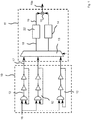
- Fig. 1 shows a graphical representation of an example for an arrangement for key generation.
- the arrangement comprises a physical unclonable function (PUF) module 10 and a key generation module 11.
- the PUF module 10 comprises a plurality ( N ) ring oscillators 12.
- the key generation module 11 comprises an N -to-2 multiplexer 13, counters 14, and a comparator 15.
- the ring oscillators 12 are activated by an enable signal 16 and subsequently provide PUF signals 17 to the multiplexer 13.
- the multiplexer 13 outputs multiplexed signal pairs 18 to the counters 14, which in turn provide further signals 19 to the comparator 15.
- a PUF-circuit pair is selected by an N -to-2 multiplexer 13, and a 1-bit is provided by the comparator 15 as output signal 19a if a first PUF-circuit has a higher counter output than a second PUF circuit and a 0-bit as output signal 19a, otherwise.
- Fig. 2 shows a graphical representation of an arrangement for decorrelating PUF signals, comprising a PUF module 10, a decorrelation module 20 (provided with, for example, one or more processors), and a post-processing module 21.
- the post-processing module 21 comprises a histogram equalization module 22, a quantization module 23, a bit allocation module 24, and a concatenation module 25.
- the PUF module 10 outputs correlated PUF signals 17, which may be represented by vectors.
- the correlations may be due to, e.g., surrounding logical elements.
- the PUF signals 17 are decorrelated in the decorrelation module 20 to output signals 20a.
- the histogram equalization module 22 converts the probability density of each of the output signals 20a (transform coefficients) into a standard normal distribution so that subsequent quantization steps for all of the output signals 22a are thus the same. Without histogram equalization, a different quantization procedure for each of the output signals 20a would be necessary. Therefore, performing histogram equalization reduces storage in the quantization module 23.
- the different modules referred to above may be provided by hardware implementation in combination with one or more software applications.
- Equalized signals 22a are independent if the PUF signals 17 are perfectly decorrelated in the decorrelation module 20 and are jointly Gaussian.
- a scalar quantizer in the quantization module 23 can be employed without performance loss.
- a scalar quantizer and a bit extraction method in the bit allocation module 24 that satisfies security and reliability requirements may be provided with the independence assumption for the output signals 20a and the equalized signals 22a.
- the bit allocation module 24 may comprise a Gray mapping, ensuring neighboring quantization intervals to result in only 1-bit changes.
- the concatenation module 25 sequentially collects all bits allocated by the bit allocation module 24 and concatenates them to obtain a single bit sequence as the output.
- the table illustrates the strength of the method with elements +1 and -1. Further, proposed-RO-PUF occupies an approximately 11 % smaller than the benchmark PUFKY / ROPUF hardware implementation in terms of the number of slices used. This result can be further improved. Furthermore, the overall processing time of the proposed design is approximately 1.68 ms, which is significantly better than a processing delay of the PUFKY / ROPUF hardware implementation.
- a linear gain in the reliability will provide a significantly higher (nonlinear due to nonlinearity of the capacity of a binary symmetric channel (BSC)) gain in terms of secret-key rate (or channel coding rate) of the chosen error-correcting code.
- BSC binary symmetric channel
- the error probabilities are estimated using following setup.
- a ring oscillator (RO) dataset consisting of measurements from 193 different Xilinx Sparten (XC3S500E) chips with 16 ⁇ 16 arrays, i.e., 256 RO outputs in each chip, was provided.
- XC3S500E Xilinx Sparten
- 256 transform coefficients only 255 coefficients are used since a first coefficient (corresponding to a DC coefficient that is the coefficient at the zero frequency in the frequency domain), corresponds to an average RO output over the PUF array in a device, which is generally known by an eavesdropper.
- a resulting RO dataset consists of 100 noisy measurements of each RO.
- Fig. 3 shows a graphical representation of the average bit error probabilities 30 for different generated decorrelation matrices.
- Each generated decorrelation matrix is associated with an index on an x -axis 31.
- a y-axis 32 represents magnitudes of the average bit error probabilities 30 for each index i / decorrelation matrix.
- the average bit error probabilities 30 vary significantly for the generated decorrelation matrices.
- L 3
- an overall average bit error probability 33, obtained by further averaging over all decorrelation matrices is 0.017, which is smaller than a DCT average bit error probability 34 of 0.0199, which was the best result in the RO-PUF literature until now, obtained by employing a discrete cosine transform / DCT matrix as the decorrelation matrix.
- the smallest value of average bit error probabilities 30 (associated with a lowest-error decorrelation matrix) is 0.0081, which is significantly smaller than the average error probability values obtained by DCT, KLT, DWHT, or DHT.
- the capacity for the DCT case is calculated as 0.8591 bits and for the lowest-error decorrelation matrix as 0.9321 bits. This further gain in secret-key capacity can be used to increase a channel code rate or to employ a simpler decoder for fixed channel codes.
- the lowest-error-probability decorrelation matrix does not comprise an obvious structure or relation to DCT, DWHT, KLT, or DHT matrices. This illustrates an advantage of generating decorrelation matrices as presently disclosed since signals from physical identifiers perform significantly better in terms of reliability. Still, due to only using entries that are 1 or -1 and employing an adapted selection for generating the decorrelation matrices, a small hardware area for implementation is ensured.
Landscapes
- Engineering & Computer Science (AREA)
- Computer Security & Cryptography (AREA)
- Computer Networks & Wireless Communication (AREA)
- Signal Processing (AREA)
- Complex Calculations (AREA)
Abstract
Description
- The present disclosure refers to a method and a system for decorrelating input signals from a physical identifier.
- Physical identifiers such as physical unclonable functions (PUFs) are heuristically defined to be complex challenge response mappings that depend on the random variations in a physical object. Uniformly random sequences are derived from this complex mapping, which can be used as a secret key. One important feature of PUFs is that the random sequence generated is not required to be stored and can be regenerated on demand. This property makes PUFs cheaper - as there is no requirement for a memory for secret storage - and safer - since the random sequence is regenerated on demand only - alternatives to other secret generation and storage techniques such as storing the secret key in a non-volatile memory (NVM).
- The standard approach for key generation using PUFs can be divided into two parts: the PUF itself and a key generation module. While the PUF provides raw data, the key generation module extracts information from the data in order to generate a reliable key. The key generation module can be divided into a source coding part (comprising an N-to-2 multiplexer, counters, and a comparator with a one bit output) that extracts useful information from the PUF-circuits and a channel coding (or error correction) part that is used to satisfy the required block error probability for the extracted key. The main source coding idea in the standard approach is to choose a PUF-circuit pair and extract a bit 1 if the first PUF-circuit has a higher counter output and, otherwise, 0.
- There are several issues with the standard approach. First, only one bit per PUF-circuit (e.g., ring oscillator (RO) pair, each of which has a semi-continuous output) is extracted. This is highly inefficient as multiple bits can be extracted from a semi-continuous output. From a continuous output, infinitely many bits are extractable in principle. Second, correlations between the PUF-circuit outputs also emerge at the extracted bits, which make the overall bit sequence vulnerable to machine learning attacks due to the correlations between the bits. Third, the channel encoder is designed for a correlated bit sequence measured through a channel with memory, which is not fully characterized by standard information theoretic metrics that are used in the literature to compare different key-extraction methods. One requires a discrete memoryless source (DMS) and a discrete memoryless channel (DMC) to apply standard information theory techniques.
- In order to overcome such issues, a transform-coding based approach that replaces the N-to-2 multiplexer in the standard approach with an orthogonal transform (e.g., a discrete cosine transform (DCT), a discrete Walsh-Hadamard transform (DWHT), a discrete Haar transform (DHT), or a Karhunen-Loeve transform (KLT)) followed by a quantization step was developed (see Günlü et. al: "Secure and reliable key agreement with physical unclonable functions", MDPI Entropy Journal, vol: 20, no: 5, May 2018).
- It is an object of the present disclosure to provide improved technology for decorrelating input signals from a physical identifier with increased reliability and decreased complexity.
- In order to solve the problem, a method for decorrelating input signals from a physical identifier according to independent claim 1 is provided. Further, a system for decorrelating input signals from a physical identifier according to
independent claim 11 is provided. Additional aspects are disclosed in dependent claims. - According to one aspect, a method for decorrelating input signals from a physical identifier is provided. In a system having one or more processors, the method comprises: providing input signals from a physical identifier; providing a decorrelation matrix; generating output signals, comprising decorrelating the input signals by applying the decorrelation matrix to the input signals; and providing the output signals at an output. The providing of the decorrelation matrix comprises: providing an initial matrix, the initial matrix being an orthogonal matrix; and determining the decorrelation matrix from the initial matrix by at least once selecting and applying at least one of a plurality of matrix extensions on the initial matrix, wherein each of the plurality of matrix extensions generates, from an input orthogonal matrix, a further orthogonal matrix with higher matrix dimension than the input orthogonal matrix.
- According to another aspect, a system for decorrelating input signals from a physical identifier is provided. The system comprises one or more processors configured to provide the following: provide input signals from a physical identifier; provide a decorrelation matrix; generate output signals, comprising decorrelating the input signals by applying the decorrelation matrix to the input signals; and provide the output signals at an output. The one or more processors are further configured for, in the step of providing the decorrelation matrix: providing an initial matrix, the initial matrix being an orthogonal matrix; and determining the decorrelation matrix from the initial matrix by at least once selecting and applying at least one of a plurality of matrix extensions on the initial matrix, wherein each of the plurality of matrix extensions generates, from an input orthogonal matrix, a further orthogonal matrix with higher matrix dimension than the input orthogonal matrix.
- Within the context of the present disclosure, a real-valued matrix A is referred to as orthogonal if A T A = AA T = I, wherein I is the identity matrix and A T denotes the transpose of a matrix A.
- With the method, correlations in physical identifier circuit outputs, in particular physical unclonable function (PUF) circuit outputs, may be significantly reduced compared to one-bit extraction methods per PUF-circuit pair. Thus, security may be increased, in particular against machine learning attacks.
- The generated decorrelation matrices (transform matrices) may provide similar and close to optimal decorrelation efficiency results, the choice of the decorrelation matrix therefore not imposing an extra security loss.
- The method allows to design quantizers based on reliabilities of the output signals (also called transform coefficients) so that error-correcting codes and the quantizers can be jointly designed, which provides higher flexibility in quantizer design when an error-correcting code is given / fixed and vice versa.
- When modeling each transform coefficient, samples from different chips with the same PUF-circuit design may be collected so that fitted models to noiseless transform coefficients are considering a whole (or available) set of chips that use the same PUF-circuit designs, in contrast to classic assumptions that raw noiseless PUF-circuit outputs in different chips are independent, which is not true for many PUF types.
- It may be provided that an optimal decorrelation matrix providing the smallest (bit) error probability for a specific PUF type can be used. Thus, any gain in the error probability may further allow the error-correction code's decoder, which corrects the errors in the erroneous (noisy) bit sequence generated from noisy transform coefficients, to be significantly simpler (i.e., yielding lower complexity in terms of the hardware area, the main bottleneck for PUF applications). Thus, complexity may be further decreased and the secret-key size for a fixed number of bits extracted from the transform coefficients may be increased jointly.
- The input signals may be semi-continuous or continuous. The input signals may be noisy or, alternatively, (essentially) noiseless. The input signals may be correlated.
- For each application step, one matrix extension among the plurality of matrix extensions may be selected and applied. In particular, a first transformation of the plurality of transformations may be selected and applied on the initial (first) matrix. On a resulting second matrix, a selected second transformation of the plurality of transformations may be applied. Further, on a resulting third matrix, a selected third transformation of the plurality of transformations may be applied. Corresponding steps may be carried until a predetermined size for the decorrelation matrix is reached.
- The method may be used for providing a secure and low-complexity source of a secret key for, e.g., secret key generation in a fifth generation (5G) mobile device via static random access memory (SRAM) outputs, device authentication and identification in a field programmable gate array (FPGA), intellectual property (IP) protection in hardware / software, encryption / decryption of data before data storage in a cloud or in a controller area network (CAN) bus standard used in modern vehicles to provide security against safety-critical attacks to the throttle and brake, Internet-of-Things (IoT) security and privacy, radio frequency identification (RFID) device security, non-repudiation (i.e., undeniable transmission or reception of data), proof of execution on a specific processor, and as a local source of randomness required in physical-layer security (PLS) applications such as secure transmission of a message over a wiretap channel.
- The physical identifier may be a physical unclonable function (PUF). According to an embodiment, a physical unclonable function (PUF) is a physical object that for a given input (input signals) and conditions (challenge), provides a physically-defined "digital fingerprint" output (response, output signals) that serves as a unique identifier, often for a semiconductor device such as a microprocessor. PUFs, for example, may be based on unique physical variations which occur during semiconductor manufacturing. In general, a PUF is a physical entity embodied in a physical structure. PUFs may be implemented in integrated circuits and may be used in applications with high security requirements, more specifically cryptography.
- The physical identifier may comprise ring oscillators (RO). The physical identifier may in particular be at least one of a ring oscillator PUF (RO-PUF), a static random-access memory (SRAM) PUF, a dynamic random-access memory (DRAM) PUF, a Butterfly PUF, a flash PUF, and a Memristor PUF.
- The determining of the decorrelation matrix from the initial matrix may comprise (adaptively) selecting at least one of the plurality of transformations dependent on the input signals. The selecting may in particular be carried out dependent on physical identifier output statistics, in particular, a reliability performance with regard to the physical identifier. The selecting may be carried out dependent on the smallest error probability resulting from the physical identifier.
- The initial matrix may be a 2 × 2 matrix. Alternatively, the initial matrix may be a 4 × 4 matrix or a 8 × 8 matrix.
- It may be provided that for each extension of the plurality of matrix extensions, the input orthogonal matrix is a k × k matrix and the further orthogonal matrix is a 2k × 2k matrix, k being a positive integer. Thus, by applying one of the plurality of matrix extensions, the matrix dimensions of the resulting further orthogonal matrix may be twice the dimensions of the input orthogonal matrix.
- The decorrelation matrix determined from the initial matrix may be a 2 n × 2 n matrix, n being a positive integer. The matrix dimension of the decorrelation matrix may thus be a power of two. This is particularly the case when the initial matrix is a 2 × 2 matrix and the matrix dimension is doubled by each application of one of the plurality of matrix extensions. In particular, the decorrelation matrix can be a 4 × 4, 8 × 8, 16 × 16, 32 × 32, 64 × 64, 128 × 128, 256 × 256, or 512 × 512 matrix.
- The plurality of matrix extensions may comprise following mappings:
- A ↦ [A, A; A, -A],
- A ↦ [A, A; -A, A],
- A ↦ [A, -A; A, A],
- A ↦ [-A, A; A, A],
- A ↦ -[A, A; A, -A],
- A ↦ -[A, A; -A, A],
- A ↦ -[A, -A; A, A], and
- A ↦ - [-A, A; A, A],
- A matrix extension among the plurality of matrix extensions may be a negative version of another extension of the plurality of matrix extensions. In this case, operations for the negative version may be different from each positive version due to a signed representation of transform coefficient values, which can likely affect a total number of operations and required hardware area.
- The initial matrix may be composed of matrix entries that are 1 or -1. Alternatively, the initial matrix may also comprise further real-valued matrix entries.
- When using matrix entries that are 1 or -1, manufacturers are provided with a small set of well performing transforms in terms of decorrelation efficiency (related to secrecy leakage), hardware complexity, privacy leakage, and decoder design for chosen / fixed error-correcting codes. By using matrix entries that are 1 or -1, particularly small hardware areas may be achieved. Further, multiplications may be avoided because a matrix multiplication with matrix entries that are only 1 or -1 can be implemented by using addition operations in the hardware.
- The initial matrix may [1, 1; 1, -1]. Alternatively, the initial matrix may be one of [1, 1; -1, 1], [1, -1; 1, 1], [-1, 1; 1, 1], -[1, 1; 1, -1], -[1, 1; -1, 1], -[1, -1; 1, 1], or -[-1, 1; 1, 1].
- The decorrelation matrix may be:

- The output signals may be post-processed, in particular using at least one of histogram equalization, quantization, bit allocation, and concatenation. A bit sequence Xn (or its noisy version Yn) used in key agreement methods such as fuzzy commitment scheme (FCS) may be extracted from the output signals. The output signals may be post-processed for enrollment, when an encoder observes the bit sequence Xn to extract a secret key and public side information. The output signals may also be post-processed for reconstruction, when a decoder observes Yn and the public side information to extract the same key as the encoder. During enrollment, design parameters may be chosen as a function of source and noise statistics by a device manufacturer.
- Alternatively, a 4-point (4P)- two-dimensional (2D) transforms may be applied that take four inputs [X0, X1, X2, X3] and calculates the transform coefficients, e.g., for one of the matrix extensions in the plurality of matrix extensions obtained, as


- Successively the 4P-2D transforms may be applied to the 16 x 16 RO array and implement a finite state machine (FSM) to control the input and output AXI streaming interfaces as well as the successive application order for the 4P-2D. The building blocks may comprise at least one of the following: a data random access memory (RAM) to store all array elements; a 32-bit index read-only memory (ROM), where each word stores four 8-bit array-element addresses; a multiplexer (MUX) to select the RAM address to be accessed; a second MUX to select the ROM input; and a register for each input to convey different RAM words to different ports.
- All RO outputs may be first stored in the data RAM. Then, the first word of the index ROM is fetched. This word holds the addresses of four array elements to be loaded. These array elements are passed to the 4P-2D transforms' input registers by selecting the corresponding port in the address MUX and register bank. After evaluating the 4P-2D transform once, the new array elements [Y0, Y1, Y2, Y3] may be written back to the locations from where the inputs [X0, X1, X2, X3] were fetched. The FSM performs the same steps for all remaining ROM words and conveys the final 16 x 16 2D transform coefficients to the AXI output port.
- The addition and subtraction operations on four numbers in each 4P-2D transform evaluation requires at most two additional bits, while the subsequent bit shift to implement the division by 2 removes one bit. Since the 4P-2D transform is applied in total four times to each RAM location, the transform requires 20-bit operations and storage in order to process the 16-bit signed numbers used for counter values.
- In the following, embodiments, by way of example, are described with reference to figures. In the figures, show:
- Fig. 1
- a graphical representation of an arrangement for key generation according to the state of the art;
- Fig. 2
- a graphical representation of an arrangement for decorrelating PUF signals; and
- Fig. 3
- a graphical representation of average bit error probabilities for different generated decorrelation matrices.
-
Fig. 1 shows a graphical representation of an example for an arrangement for key generation. The arrangement comprises a physical unclonable function (PUF)module 10 and akey generation module 11. ThePUF module 10 comprises a plurality (N)ring oscillators 12. Thekey generation module 11 comprises an N-to-2multiplexer 13, counters 14, and acomparator 15. - The ring oscillators 12 are activated by an
enable signal 16 and subsequently provide PUF signals 17 to themultiplexer 13. Themultiplexer 13 outputs multiplexed signal pairs 18 to thecounters 14, which in turn providefurther signals 19 to thecomparator 15. In the standard approach, a PUF-circuit pair is selected by an N-to-2multiplexer 13, and a 1-bit is provided by thecomparator 15 asoutput signal 19a if a first PUF-circuit has a higher counter output than a second PUF circuit and a 0-bit asoutput signal 19a, otherwise. -
Fig. 2 shows a graphical representation of an arrangement for decorrelating PUF signals, comprising aPUF module 10, a decorrelation module 20 (provided with, for example, one or more processors), and apost-processing module 21. Thepost-processing module 21 comprises ahistogram equalization module 22, aquantization module 23, abit allocation module 24, and aconcatenation module 25. - The
PUF module 10 outputs correlated PUF signals 17, which may be represented by vectors. The correlations may be due to, e.g., surrounding logical elements. The PUF signals 17 are decorrelated in thedecorrelation module 20 tooutput signals 20a. - The
histogram equalization module 22 converts the probability density of each of theoutput signals 20a (transform coefficients) into a standard normal distribution so that subsequent quantization steps for all of theoutput signals 22a are thus the same. Without histogram equalization, a different quantization procedure for each of theoutput signals 20a would be necessary. Therefore, performing histogram equalization reduces storage in thequantization module 23. - The different modules referred to above may be provided by hardware implementation in combination with one or more software applications.
- Equalized signals 22a are independent if the PUF signals 17 are perfectly decorrelated in the
decorrelation module 20 and are jointly Gaussian. Thus, in this case, a scalar quantizer in thequantization module 23 can be employed without performance loss. A scalar quantizer and a bit extraction method in thebit allocation module 24 that satisfies security and reliability requirements may be provided with the independence assumption for theoutput signals 20a and the equalizedsignals 22a. Thebit allocation module 24 may comprise a Gray mapping, ensuring neighboring quantization intervals to result in only 1-bit changes. Theconcatenation module 25 sequentially collects all bits allocated by thebit allocation module 24 and concatenates them to obtain a single bit sequence as the output. - Following table shows hardware implementation results for decorrelating PUF signals using the method in comparison with a benchmark design (PUFKY / ROPUF). A two-dimensional (2D) 16 x 16 DWHT with a one-bit quantizer for all transform coefficients was implemented (Proposed-DWHT). The DWHT has elements 1 and -1 in its transform matrix. Therefore, the results in the table are closely approximating the hardware complexity of the proposed
decorrelation module 20. In the table, the number of used lookup tables (LUT), registers, multiplexers (MUXes), random access memory (RAM), read-only memory (ROM), and configurable logic blocks (CLBs) or slices that comprise a collection of basic logic blocks in an FPGA are listed in addition to the computation duration / delay.Blocks LUTs Registers MUXes RAM&ROM [Byte] Slices Duration [µs] Proposed-ROs 1632 397 65 0 729 1600 Proposed-DWHT 326 200 0 1664 99 66 Proposed-Quantizer 43 39 0 638 21 14 Proposed (ROPUF) 2001 636 65 2302 849 1680 PUFKY (ROPUF) n.a. n.a. n.a. n.a. 952 4611 - The table illustrates the strength of the method with elements +1 and -1. Further, proposed-RO-PUF occupies an approximately 11 % smaller than the benchmark PUFKY / ROPUF hardware implementation in terms of the number of slices used. This result can be further improved. Furthermore, the overall processing time of the proposed design is approximately 1.68 ms, which is significantly better than a processing delay of the PUFKY / ROPUF hardware implementation.
- Conducted experiments suggest that a decorrelation efficiency of each transform is high and close to optimal. In addition, the method to be applied to any correlated PUF-circuit output provides a flexible way for determining and implementing the best decorrelation matrix. Implementation can be carried out by minor adaptations. Each decorrelation module chosen from the set of transforms obtained using the matrix extensions will likely result in a similar hardware area; and reliability will be maximized so that error-correcting code's decoder, which corrects the errors in the noisy bit sequence obtained from the noisy transform coefficients to reconstruct the secret key generated from the noiseless transform coefficients, is simplified.
- A linear gain in the reliability will provide a significantly higher (nonlinear due to nonlinearity of the capacity of a binary symmetric channel (BSC)) gain in terms of secret-key rate (or channel coding rate) of the chosen error-correcting code. This provides flexibility to use a lower-complexity decoder or to extract more secret-key bits for a fixed number of extracted PUF bits.
- The error probabilities are estimated using following setup. A ring oscillator (RO) dataset consisting of measurements from 193 different Xilinx Sparten (XC3S500E) chips with 16×16 arrays, i.e., 256 RO outputs in each chip, was provided. Among 256 transform coefficients, only 255 coefficients are used since a first coefficient (corresponding to a DC coefficient that is the coefficient at the zero frequency in the frequency domain), corresponds to an average RO output over the PUF array in a device, which is generally known by an eavesdropper. A resulting RO dataset consists of 100 noisy measurements of each RO.
- In order to estimate the error probabilities, following steps are carried out:
- Mean values are calculated for each RO from 100 noisy measurements to estimate the noiseless RO outputs as each noisy RO output is modeled as noiseless RO output added by a noise component with zero mean. The zero mean random noise model fits well to the digital circuits mainly due to the random (or uncontrollable) local temperature and voltage variations in digital chips.
- For each chip with a 16 x 16 RO array with the same circuit design, a chosen decorrelation matrix (transform matrix) is applied to the noiseless RO outputs to determine the noiseless transform coefficients. The same transform is applied to each chip's noiseless RO outputs. Thus, for each transform coefficient, 193 samples are obtained, each of which originates from one chip among 193 chips in the used dataset.
- Mean and variance values for each noiseless transform coefficient (in total 255) are estimated by using the transform coefficients obtained from each chip's noiseless RO outputs.
- One of the chips is chosen in order to subsequently use its 100 noisy measurements so that one can estimate the parameters of the random noise component in the transform domain.
- A specified transform (decorrelation matrix) is applied to noisy RO outputs in order to obtain a set of 100 different values for each noisy transform coefficient.
- Each of the 100 noisy transform coefficients is subtracted from each of the 100 noiseless transform coefficients obtained in the second step above, yielding 100 resultant noise samples per transform coefficient.
- Mean and variance values for each noise component on each transform coefficient are estimated from the 100 resultant noise samples.
- After estimating the mean and the variance for both noiseless transform coefficients and noise components, where a noisy transform coefficient output = noiseless transform coefficient + noise component on the transform coefficient, average bit error probabilities are calculated using following (Monte-Carlo simulation) steps:
- Generate noiseless and noisy transform coefficient outputs according to the estimated mean and the variance values for each noiseless transform coefficient and each noise component, respectively.
- Obtain noisy transform coefficients from the generated noiseless transform coefficient outputs and the generated noise components.
- Quantize the noiseless and noisy transform coefficient outputs into decimal values, after calculating Gaussian quantiles, dividing the range of each transform coefficient into equiprobable quantization regions, by using the mean and the variance values for each noiseless transform coefficient and each noise component.
- Map the decimal values via a Gray mapping with a corresponding quantized-bit-output length L (e.g., L = 3), yielding mapped length-L bit sequences.
- Compare the mapped values in order to estimate the average bit error probability for each decorrelation matrix.
-
Fig. 3 shows a graphical representation of the average bit error probabilities 30 for different generated decorrelation matrices. Each generated decorrelation matrix is associated with an index on anx -axis 31. A y-axis 32 represents magnitudes of the average bit error probabilities 30 for each index i / decorrelation matrix. - The average bit error probabilities 30 vary significantly for the generated decorrelation matrices. For L = 3, an overall average
bit error probability 33, obtained by further averaging over all decorrelation matrices is 0.017, which is smaller than a DCT averagebit error probability 34 of 0.0199, which was the best result in the RO-PUF literature until now, obtained by employing a discrete cosine transform / DCT matrix as the decorrelation matrix. - The smallest value of average bit error probabilities 30 (associated with a lowest-error decorrelation matrix) is 0.0081, which is significantly smaller than the average error probability values obtained by DCT, KLT, DWHT, or DHT. To illustrate a gain in secret-key capacity due to such a smaller error probability value, the capacity for the DCT case is calculated as 0.8591 bits and for the lowest-error decorrelation matrix as 0.9321 bits. This further gain in secret-key capacity can be used to increase a channel code rate or to employ a simpler decoder for fixed channel codes.
- The lowest-error-probability decorrelation matrix is:

- The lowest-error-probability decorrelation matrix does not comprise an obvious structure or relation to DCT, DWHT, KLT, or DHT matrices. This illustrates an advantage of generating decorrelation matrices as presently disclosed since signals from physical identifiers perform significantly better in terms of reliability. Still, due to only using entries that are 1 or -1 and employing an adapted selection for generating the decorrelation matrices, a small hardware area for implementation is ensured.
- The features disclosed in this specification, the figures and / or the claims may be material for the realization of various embodiments, taken in isolation or in various combinations thereof.
Claims (11)
- A method for decorrelating input signals from a physical identifier, in a system having one or more processors, comprising:- providing input signals from a physical identifier;- providing a decorrelation matrix;- generating output signals, comprising decorrelating the input signals by applying the decorrelation matrix to the input signals; and- providing the output signals at an output;
wherein the providing of the decorrelation matrix comprises- providing an initial matrix, the initial matrix being an orthogonal matrix; and- determining the decorrelation matrix from the initial matrix by at least once selecting and applying at least one of a plurality of matrix extensions on the initial matrix, wherein each of the plurality of matrix extensions generates, from an input orthogonal matrix, a further orthogonal matrix with higher matrix dimension than the input orthogonal matrix. - The method according to claim 1, wherein the physical identifier is a physical unclonable function.
- The method according to claim 1 or 2, wherein the determining of the decorrelation matrix from the initial matrix comprises adaptively selecting at least one of the plurality of matrix extensions dependent on the input signals.
- The method according to at least one of the previous claims, wherein the initial matrix is a 2 × 2 matrix.
- The method according to at least one of the previous claims, wherein for each matrix extension of the plurality of matrix extensions, the input orthogonal matrix is a k × k matrix and the output further orthogonal matrix is a 2 k × 2 k matrix, k being a positive integer.
- The method according to claims 4 and 5, wherein the decorrelation matrix determined from the initial matrix is a 2 n × 2 n matrix, n being a positive integer.
- The method according to at least one of the previous claims, wherein the plurality of matrix extensions comprises following transformations:- A [A, A; A, -A],- A ↦ [A, A; -A, A],- A ↦ [A, -A; A, A],- A ↦ [-A, A; A, A],- A ↦ -[A, A; A, -A],- A ↦ -[A, A; -A, A],- A ↦ -[A, -A; A, A], and- A ↦ - [-A, A; A, A],wherein A is the input orthogonal matrix.
- The method according to at least one of the previous claims, wherein the initial matrix is composed of matrix entries that are 1 or -1.
- The method according to claim 8, wherein the initial matrix is [1, 1; 1, -1].
- The method according to at least one of the previous claims, wherein the output signals are post-processed.
- A system for decorrelating input signals from a physical identifier, comprising one or more processors, wherein the one or more processors are configured to provide the following:- provide input signals from a physical identifier;- provide a decorrelation matrix;- generate output signals, comprising decorrelating the input signals by applying the decorrelation matrix to the input signals; and- provide the output signals at an output;
wherein the one or more processors are further configured for, in the step of providing the decorrelation matrix,- providing an initial matrix, the initial matrix being an orthogonal matrix; and- determining the decorrelation matrix from the initial matrix by at least once selecting and applying at least one of a plurality of matrix extensions on the initial matrix, wherein each of the plurality of matrix extensions generates, from an input orthogonal matrix, a further orthogonal matrix with higher matrix dimension than the input orthogonal matrix.
Priority Applications (4)
| Application Number | Priority Date | Filing Date | Title |
|---|---|---|---|
| EP20164810.2A EP3886358B1 (en) | 2020-03-23 | 2020-03-23 | Method and system for decorrelating input signals from a physical identifier |
| US17/911,581 US12335415B2 (en) | 2020-03-23 | 2021-03-22 | Method and system for decorrelating input signals from a physical identifier |
| PCT/EP2021/057263 WO2021191144A1 (en) | 2020-03-23 | 2021-03-22 | Method and system for decorrelating input signals from a physical identifier |
| CN202180023004.XA CN115315920A (en) | 2020-03-23 | 2021-03-22 | Method and system for decorrelating input signals from physical identifiers |
Applications Claiming Priority (1)
| Application Number | Priority Date | Filing Date | Title |
|---|---|---|---|
| EP20164810.2A EP3886358B1 (en) | 2020-03-23 | 2020-03-23 | Method and system for decorrelating input signals from a physical identifier |
Publications (2)
| Publication Number | Publication Date |
|---|---|
| EP3886358A1 true EP3886358A1 (en) | 2021-09-29 |
| EP3886358B1 EP3886358B1 (en) | 2022-04-27 |
Family
ID=69953833
Family Applications (1)
| Application Number | Title | Priority Date | Filing Date |
|---|---|---|---|
| EP20164810.2A Active EP3886358B1 (en) | 2020-03-23 | 2020-03-23 | Method and system for decorrelating input signals from a physical identifier |
Country Status (4)
| Country | Link |
|---|---|
| US (1) | US12335415B2 (en) |
| EP (1) | EP3886358B1 (en) |
| CN (1) | CN115315920A (en) |
| WO (1) | WO2021191144A1 (en) |
Family Cites Families (1)
| Publication number | Priority date | Publication date | Assignee | Title |
|---|---|---|---|---|
| US11294997B2 (en) * | 2018-12-18 | 2022-04-05 | Infineon Technologies Ag | Pairing devices to an authentication device by sensor fingerprinting |
-
2020
- 2020-03-23 EP EP20164810.2A patent/EP3886358B1/en active Active
-
2021
- 2021-03-22 US US17/911,581 patent/US12335415B2/en active Active
- 2021-03-22 WO PCT/EP2021/057263 patent/WO2021191144A1/en not_active Ceased
- 2021-03-22 CN CN202180023004.XA patent/CN115315920A/en active Pending
Non-Patent Citations (4)
| Title |
|---|
| CHANYUL KIM ET AL: "Low Computational Complexity Variable Block Size (VBS) Partitioning for Motion Estimation Using the Walsh Hadamard Transform (WHT)", MULTIMEDIA, 2009. ISM '09. 11TH IEEE INTERNATIONAL SYMPOSIUM ON, IEEE, PISCATAWAY, NJ, USA, 14 December 2009 (2009-12-14), pages 124 - 129, XP031589063, ISBN: 978-1-4244-5231-6 * |
| GÜNLÜ ONUR ET AL: "Reliable secret key generation from physical unclonable functions under varying environmental conditions", 2015 IEEE INTERNATIONAL WORKSHOP ON INFORMATION FORENSICS AND SECURITY (WIFS), IEEE, 16 November 2015 (2015-11-16), pages 1 - 6, XP032840426, DOI: 10.1109/WIFS.2015.7368554 * |
| GUNLU: "Secure and reliable key agreement with physical unclonable functions", MDPI ENTROPY JOURNAL, vol. 20, no. 5, May 2018 (2018-05-01) |
| ONUR GÜNLÜ ET AL: "Secure and Reliable Key Agreement with Physical Unclonable Functions", ARXIV.ORG, CORNELL UNIVERSITY LIBRARY, 201 OLIN LIBRARY CORNELL UNIVERSITY ITHACA, NY 14853, 26 February 2020 (2020-02-26), XP081608726, DOI: 10.3390/E20050340 * |
Also Published As
| Publication number | Publication date |
|---|---|
| EP3886358B1 (en) | 2022-04-27 |
| US12335415B2 (en) | 2025-06-17 |
| US20240305480A1 (en) | 2024-09-12 |
| CN115315920A (en) | 2022-11-08 |
| WO2021191144A1 (en) | 2021-09-30 |
Similar Documents
| Publication | Publication Date | Title |
|---|---|---|
| US11836368B2 (en) | Lossy data compression | |
| EP2789116B1 (en) | Soft decision error correction for memory based puf using a single enrollment | |
| US9054870B2 (en) | Information security based on eigendecomposition | |
| US20150227747A1 (en) | Information security based on eigendecomposition | |
| EP4344122A1 (en) | Protecting polynomial rejection through masked compressed comparison | |
| CN117857008B (en) | Data processing method of torus fully homomorphic encryption algorithm based on integer bootstrapping | |
| WO2018142367A1 (en) | Alteration of successive cancellation order in decoding of polar codes | |
| AU773982B2 (en) | Method for making data processing resistant to extraction of data by analysis of unintended side-channel signals | |
| Hadj Brahim et al. | A new image compression-encryption scheme based on compressive sensing & classical AES algorithm | |
| CN107481180B (en) | Image Encryption Method Based on Cellular Automata and Block Compressed Sensing | |
| Günlü et al. | Low-complexity and reliable transforms for physical unclonable functions | |
| CN112543092A (en) | Chaotic binary sequence family matrix construction method based on image compressed sensing encryption | |
| CN116491072A (en) | Encoding method, decoding method, and communication device | |
| EP3886358B1 (en) | Method and system for decorrelating input signals from a physical identifier | |
| WO2022022311A1 (en) | Method and apparatus for generating pseudo-random sequence, electronic device, and storage medium | |
| Gangadari et al. | FPGA implementation of compact S-Box for AES algorithm using composite field arithmetic | |
| Kumar et al. | XOR-free approach for implementation of polar encoder | |
| Günlü et al. | Quality of Service Guarantees for Physical Unclonable Functions | |
| Hiller et al. | Algebraic security analysis of key generation with physical unclonable functions | |
| Izu et al. | CAIRN 2: an FPGA implementation of the sieving step in the number field sieve method | |
| Elango et al. | Implementation of Partial RNS-Assisted Mutual Authentication Protocol for RFID-Enabled IoT Devices | |
| US20260081777A1 (en) | Binomial Sampling in Lattice-Based Cryptography | |
| Tian et al. | Fast Scloud+: A Fast Hardware Implementation for the Unstructured LWE-based KEM-Scloud+ | |
| Shi et al. | Polar codes for multiple descriptions | |
| Johansson | Power analysis on FPGA implementation of Classic McEliece |
Legal Events
| Date | Code | Title | Description |
|---|---|---|---|
| PUAI | Public reference made under article 153(3) epc to a published international application that has entered the european phase |
Free format text: ORIGINAL CODE: 0009012 |
|
| STAA | Information on the status of an ep patent application or granted ep patent |
Free format text: STATUS: REQUEST FOR EXAMINATION WAS MADE |
|
| 17P | Request for examination filed |
Effective date: 20201203 |
|
| AK | Designated contracting states |
Kind code of ref document: A1 Designated state(s): AL AT BE BG CH CY CZ DE DK EE ES FI FR GB GR HR HU IE IS IT LI LT LU LV MC MK MT NL NO PL PT RO RS SE SI SK SM TR |
|
| GRAP | Despatch of communication of intention to grant a patent |
Free format text: ORIGINAL CODE: EPIDOSNIGR1 |
|
| STAA | Information on the status of an ep patent application or granted ep patent |
Free format text: STATUS: GRANT OF PATENT IS INTENDED |
|
| INTG | Intention to grant announced |
Effective date: 20211105 |
|
| GRAS | Grant fee paid |
Free format text: ORIGINAL CODE: EPIDOSNIGR3 |
|
| GRAA | (expected) grant |
Free format text: ORIGINAL CODE: 0009210 |
|
| STAA | Information on the status of an ep patent application or granted ep patent |
Free format text: STATUS: THE PATENT HAS BEEN GRANTED |
|
| AK | Designated contracting states |
Kind code of ref document: B1 Designated state(s): AL AT BE BG CH CY CZ DE DK EE ES FI FR GB GR HR HU IE IS IT LI LT LU LV MC MK MT NL NO PL PT RO RS SE SI SK SM TR |
|
| REG | Reference to a national code |
Ref country code: GB Ref legal event code: FG4D |
|
| REG | Reference to a national code |
Ref country code: CH Ref legal event code: EP |
|
| REG | Reference to a national code |
Ref country code: AT Ref legal event code: REF Ref document number: 1487817 Country of ref document: AT Kind code of ref document: T Effective date: 20220515 |
|
| REG | Reference to a national code |
Ref country code: DE Ref legal event code: R096 Ref document number: 602020002792 Country of ref document: DE |
|
| REG | Reference to a national code |
Ref country code: IE Ref legal event code: FG4D |
|
| REG | Reference to a national code |
Ref country code: NL Ref legal event code: FP |
|
| REG | Reference to a national code |
Ref country code: LT Ref legal event code: MG9D |
|
| REG | Reference to a national code |
Ref country code: CH Ref legal event code: PK Free format text: BERICHTIGUNGEN |
|
| REG | Reference to a national code |
Ref country code: AT Ref legal event code: MK05 Ref document number: 1487817 Country of ref document: AT Kind code of ref document: T Effective date: 20220427 |
|
| RIN2 | Information on inventor provided after grant (corrected) |
Inventor name: SCHAEFER, RAFAEL PROF. DIPL.-ING. Inventor name: GUENLUE, ONUR DR.-ING. |
|
| PG25 | Lapsed in a contracting state [announced via postgrant information from national office to epo] |
Ref country code: SE Free format text: LAPSE BECAUSE OF FAILURE TO SUBMIT A TRANSLATION OF THE DESCRIPTION OR TO PAY THE FEE WITHIN THE PRESCRIBED TIME-LIMIT Effective date: 20220427 Ref country code: PT Free format text: LAPSE BECAUSE OF FAILURE TO SUBMIT A TRANSLATION OF THE DESCRIPTION OR TO PAY THE FEE WITHIN THE PRESCRIBED TIME-LIMIT Effective date: 20220829 Ref country code: NO Free format text: LAPSE BECAUSE OF FAILURE TO SUBMIT A TRANSLATION OF THE DESCRIPTION OR TO PAY THE FEE WITHIN THE PRESCRIBED TIME-LIMIT Effective date: 20220727 Ref country code: LT Free format text: LAPSE BECAUSE OF FAILURE TO SUBMIT A TRANSLATION OF THE DESCRIPTION OR TO PAY THE FEE WITHIN THE PRESCRIBED TIME-LIMIT Effective date: 20220427 Ref country code: HR Free format text: LAPSE BECAUSE OF FAILURE TO SUBMIT A TRANSLATION OF THE DESCRIPTION OR TO PAY THE FEE WITHIN THE PRESCRIBED TIME-LIMIT Effective date: 20220427 Ref country code: GR Free format text: LAPSE BECAUSE OF FAILURE TO SUBMIT A TRANSLATION OF THE DESCRIPTION OR TO PAY THE FEE WITHIN THE PRESCRIBED TIME-LIMIT Effective date: 20220728 Ref country code: FI Free format text: LAPSE BECAUSE OF FAILURE TO SUBMIT A TRANSLATION OF THE DESCRIPTION OR TO PAY THE FEE WITHIN THE PRESCRIBED TIME-LIMIT Effective date: 20220427 Ref country code: BG Free format text: LAPSE BECAUSE OF FAILURE TO SUBMIT A TRANSLATION OF THE DESCRIPTION OR TO PAY THE FEE WITHIN THE PRESCRIBED TIME-LIMIT Effective date: 20220727 Ref country code: AT Free format text: LAPSE BECAUSE OF FAILURE TO SUBMIT A TRANSLATION OF THE DESCRIPTION OR TO PAY THE FEE WITHIN THE PRESCRIBED TIME-LIMIT Effective date: 20220427 |
|
| PG25 | Lapsed in a contracting state [announced via postgrant information from national office to epo] |
Ref country code: RS Free format text: LAPSE BECAUSE OF FAILURE TO SUBMIT A TRANSLATION OF THE DESCRIPTION OR TO PAY THE FEE WITHIN THE PRESCRIBED TIME-LIMIT Effective date: 20220427 Ref country code: PL Free format text: LAPSE BECAUSE OF FAILURE TO SUBMIT A TRANSLATION OF THE DESCRIPTION OR TO PAY THE FEE WITHIN THE PRESCRIBED TIME-LIMIT Effective date: 20220427 Ref country code: LV Free format text: LAPSE BECAUSE OF FAILURE TO SUBMIT A TRANSLATION OF THE DESCRIPTION OR TO PAY THE FEE WITHIN THE PRESCRIBED TIME-LIMIT Effective date: 20220427 Ref country code: IS Free format text: LAPSE BECAUSE OF FAILURE TO SUBMIT A TRANSLATION OF THE DESCRIPTION OR TO PAY THE FEE WITHIN THE PRESCRIBED TIME-LIMIT Effective date: 20220827 |
|
| REG | Reference to a national code |
Ref country code: DE Ref legal event code: R097 Ref document number: 602020002792 Country of ref document: DE |
|
| PG25 | Lapsed in a contracting state [announced via postgrant information from national office to epo] |
Ref country code: SM Free format text: LAPSE BECAUSE OF FAILURE TO SUBMIT A TRANSLATION OF THE DESCRIPTION OR TO PAY THE FEE WITHIN THE PRESCRIBED TIME-LIMIT Effective date: 20220427 Ref country code: SK Free format text: LAPSE BECAUSE OF FAILURE TO SUBMIT A TRANSLATION OF THE DESCRIPTION OR TO PAY THE FEE WITHIN THE PRESCRIBED TIME-LIMIT Effective date: 20220427 Ref country code: RO Free format text: LAPSE BECAUSE OF FAILURE TO SUBMIT A TRANSLATION OF THE DESCRIPTION OR TO PAY THE FEE WITHIN THE PRESCRIBED TIME-LIMIT Effective date: 20220427 Ref country code: ES Free format text: LAPSE BECAUSE OF FAILURE TO SUBMIT A TRANSLATION OF THE DESCRIPTION OR TO PAY THE FEE WITHIN THE PRESCRIBED TIME-LIMIT Effective date: 20220427 Ref country code: EE Free format text: LAPSE BECAUSE OF FAILURE TO SUBMIT A TRANSLATION OF THE DESCRIPTION OR TO PAY THE FEE WITHIN THE PRESCRIBED TIME-LIMIT Effective date: 20220427 Ref country code: DK Free format text: LAPSE BECAUSE OF FAILURE TO SUBMIT A TRANSLATION OF THE DESCRIPTION OR TO PAY THE FEE WITHIN THE PRESCRIBED TIME-LIMIT Effective date: 20220427 Ref country code: CZ Free format text: LAPSE BECAUSE OF FAILURE TO SUBMIT A TRANSLATION OF THE DESCRIPTION OR TO PAY THE FEE WITHIN THE PRESCRIBED TIME-LIMIT Effective date: 20220427 |
|
| PLBE | No opposition filed within time limit |
Free format text: ORIGINAL CODE: 0009261 |
|
| STAA | Information on the status of an ep patent application or granted ep patent |
Free format text: STATUS: NO OPPOSITION FILED WITHIN TIME LIMIT |
|
| PG25 | Lapsed in a contracting state [announced via postgrant information from national office to epo] |
Ref country code: AL Free format text: LAPSE BECAUSE OF FAILURE TO SUBMIT A TRANSLATION OF THE DESCRIPTION OR TO PAY THE FEE WITHIN THE PRESCRIBED TIME-LIMIT Effective date: 20220427 |
|
| 26N | No opposition filed |
Effective date: 20230130 |
|
| PG25 | Lapsed in a contracting state [announced via postgrant information from national office to epo] |
Ref country code: MC Free format text: LAPSE BECAUSE OF FAILURE TO SUBMIT A TRANSLATION OF THE DESCRIPTION OR TO PAY THE FEE WITHIN THE PRESCRIBED TIME-LIMIT Effective date: 20220427 |
|
| REG | Reference to a national code |
Ref country code: BE Ref legal event code: MM Effective date: 20230331 |
|
| PG25 | Lapsed in a contracting state [announced via postgrant information from national office to epo] |
Ref country code: LU Free format text: LAPSE BECAUSE OF NON-PAYMENT OF DUE FEES Effective date: 20230323 |
|
| REG | Reference to a national code |
Ref country code: IE Ref legal event code: MM4A |
|
| PG25 | Lapsed in a contracting state [announced via postgrant information from national office to epo] |
Ref country code: IT Free format text: LAPSE BECAUSE OF FAILURE TO SUBMIT A TRANSLATION OF THE DESCRIPTION OR TO PAY THE FEE WITHIN THE PRESCRIBED TIME-LIMIT Effective date: 20220427 Ref country code: IE Free format text: LAPSE BECAUSE OF NON-PAYMENT OF DUE FEES Effective date: 20230323 |
|
| PG25 | Lapsed in a contracting state [announced via postgrant information from national office to epo] |
Ref country code: BE Free format text: LAPSE BECAUSE OF NON-PAYMENT OF DUE FEES Effective date: 20230331 |
|
| PGFP | Annual fee paid to national office [announced via postgrant information from national office to epo] |
Ref country code: NL Payment date: 20240320 Year of fee payment: 5 |
|
| PGFP | Annual fee paid to national office [announced via postgrant information from national office to epo] |
Ref country code: CH Payment date: 20240401 Year of fee payment: 5 |
|
| PG25 | Lapsed in a contracting state [announced via postgrant information from national office to epo] |
Ref country code: BG Free format text: LAPSE BECAUSE OF FAILURE TO SUBMIT A TRANSLATION OF THE DESCRIPTION OR TO PAY THE FEE WITHIN THE PRESCRIBED TIME-LIMIT Effective date: 20220427 |
|
| PG25 | Lapsed in a contracting state [announced via postgrant information from national office to epo] |
Ref country code: BG Free format text: LAPSE BECAUSE OF FAILURE TO SUBMIT A TRANSLATION OF THE DESCRIPTION OR TO PAY THE FEE WITHIN THE PRESCRIBED TIME-LIMIT Effective date: 20220427 |
|
| PG25 | Lapsed in a contracting state [announced via postgrant information from national office to epo] |
Ref country code: CY Free format text: LAPSE BECAUSE OF FAILURE TO SUBMIT A TRANSLATION OF THE DESCRIPTION OR TO PAY THE FEE WITHIN THE PRESCRIBED TIME-LIMIT; INVALID AB INITIO Effective date: 20200323 |
|
| PG25 | Lapsed in a contracting state [announced via postgrant information from national office to epo] |
Ref country code: HU Free format text: LAPSE BECAUSE OF FAILURE TO SUBMIT A TRANSLATION OF THE DESCRIPTION OR TO PAY THE FEE WITHIN THE PRESCRIBED TIME-LIMIT; INVALID AB INITIO Effective date: 20200323 |
|
| REG | Reference to a national code |
Ref country code: CH Ref legal event code: H13 Free format text: ST27 STATUS EVENT CODE: U-0-0-H10-H13 (AS PROVIDED BY THE NATIONAL OFFICE) Effective date: 20251024 |
|
| REG | Reference to a national code |
Ref country code: NL Ref legal event code: MM Effective date: 20250401 |
|
| PG25 | Lapsed in a contracting state [announced via postgrant information from national office to epo] |
Ref country code: TR Free format text: LAPSE BECAUSE OF FAILURE TO SUBMIT A TRANSLATION OF THE DESCRIPTION OR TO PAY THE FEE WITHIN THE PRESCRIBED TIME-LIMIT Effective date: 20220427 |
|
| PG25 | Lapsed in a contracting state [announced via postgrant information from national office to epo] |
Ref country code: NL Free format text: LAPSE BECAUSE OF NON-PAYMENT OF DUE FEES Effective date: 20250401 |
|
| PG25 | Lapsed in a contracting state [announced via postgrant information from national office to epo] |
Ref country code: CH Free format text: LAPSE BECAUSE OF NON-PAYMENT OF DUE FEES Effective date: 20250331 |
|
| PG25 | Lapsed in a contracting state [announced via postgrant information from national office to epo] |
Ref country code: SI Free format text: LAPSE BECAUSE OF FAILURE TO SUBMIT A TRANSLATION OF THE DESCRIPTION OR TO PAY THE FEE WITHIN THE PRESCRIBED TIME-LIMIT Effective date: 20220427 |
|
| PGFP | Annual fee paid to national office [announced via postgrant information from national office to epo] |
Ref country code: GB Payment date: 20260324 Year of fee payment: 7 |
|
| PGFP | Annual fee paid to national office [announced via postgrant information from national office to epo] |
Ref country code: DE Payment date: 20260320 Year of fee payment: 7 |
|
| PGFP | Annual fee paid to national office [announced via postgrant information from national office to epo] |
Ref country code: FR Payment date: 20260325 Year of fee payment: 7 |