EP3886308A1 - Power conversion systems and methods - Google Patents
Power conversion systems and methods Download PDFInfo
- Publication number
- EP3886308A1 EP3886308A1 EP21164417.4A EP21164417A EP3886308A1 EP 3886308 A1 EP3886308 A1 EP 3886308A1 EP 21164417 A EP21164417 A EP 21164417A EP 3886308 A1 EP3886308 A1 EP 3886308A1
- Authority
- EP
- European Patent Office
- Prior art keywords
- switches
- power converter
- hybrid power
- phase unit
- controller
- Prior art date
- Legal status (The legal status is an assumption and is not a legal conclusion. Google has not performed a legal analysis and makes no representation as to the accuracy of the status listed.)
- Pending
Links
- 238000000034 method Methods 0.000 title claims abstract description 19
- 238000006243 chemical reaction Methods 0.000 title claims abstract description 17
- 238000004891 communication Methods 0.000 claims abstract description 20
- 230000007935 neutral effect Effects 0.000 claims description 5
- 230000035882 stress Effects 0.000 description 12
- 230000008646 thermal stress Effects 0.000 description 12
- 238000001816 cooling Methods 0.000 description 4
- 238000013459 approach Methods 0.000 description 3
- 239000003990 capacitor Substances 0.000 description 2
- 238000010399 three-hybrid screening Methods 0.000 description 2
- 230000007704 transition Effects 0.000 description 2
- 238000007796 conventional method Methods 0.000 description 1
- 238000007599 discharging Methods 0.000 description 1
- 238000012986 modification Methods 0.000 description 1
- 230000004048 modification Effects 0.000 description 1
- 238000012544 monitoring process Methods 0.000 description 1
- 238000005204 segregation Methods 0.000 description 1
- 239000004065 semiconductor Substances 0.000 description 1
Images




Classifications
-
- H—ELECTRICITY
- H02—GENERATION; CONVERSION OR DISTRIBUTION OF ELECTRIC POWER
- H02M—APPARATUS FOR CONVERSION BETWEEN AC AND AC, BETWEEN AC AND DC, OR BETWEEN DC AND DC, AND FOR USE WITH MAINS OR SIMILAR POWER SUPPLY SYSTEMS; CONVERSION OF DC OR AC INPUT POWER INTO SURGE OUTPUT POWER; CONTROL OR REGULATION THEREOF
- H02M7/00—Conversion of AC power input into DC power output; Conversion of DC power input into AC power output
- H02M7/42—Conversion of DC power input into AC power output without possibility of reversal
- H02M7/44—Conversion of DC power input into AC power output without possibility of reversal by static converters
- H02M7/48—Conversion of DC power input into AC power output without possibility of reversal by static converters using discharge tubes with control electrode or semiconductor devices with control electrode
- H02M7/53—Conversion of DC power input into AC power output without possibility of reversal by static converters using discharge tubes with control electrode or semiconductor devices with control electrode using devices of a triode or transistor type requiring continuous application of a control signal
- H02M7/537—Conversion of DC power input into AC power output without possibility of reversal by static converters using discharge tubes with control electrode or semiconductor devices with control electrode using devices of a triode or transistor type requiring continuous application of a control signal using semiconductor devices only, e.g. single switched pulse inverters
- H02M7/539—Conversion of DC power input into AC power output without possibility of reversal by static converters using discharge tubes with control electrode or semiconductor devices with control electrode using devices of a triode or transistor type requiring continuous application of a control signal using semiconductor devices only, e.g. single switched pulse inverters with automatic control of output wave form or frequency
- H02M7/5395—Conversion of DC power input into AC power output without possibility of reversal by static converters using discharge tubes with control electrode or semiconductor devices with control electrode using devices of a triode or transistor type requiring continuous application of a control signal using semiconductor devices only, e.g. single switched pulse inverters with automatic control of output wave form or frequency by pulse-width modulation
-
- H—ELECTRICITY
- H02—GENERATION; CONVERSION OR DISTRIBUTION OF ELECTRIC POWER
- H02M—APPARATUS FOR CONVERSION BETWEEN AC AND AC, BETWEEN AC AND DC, OR BETWEEN DC AND DC, AND FOR USE WITH MAINS OR SIMILAR POWER SUPPLY SYSTEMS; CONVERSION OF DC OR AC INPUT POWER INTO SURGE OUTPUT POWER; CONTROL OR REGULATION THEREOF
- H02M7/00—Conversion of AC power input into DC power output; Conversion of DC power input into AC power output
- H02M7/42—Conversion of DC power input into AC power output without possibility of reversal
- H02M7/44—Conversion of DC power input into AC power output without possibility of reversal by static converters
- H02M7/48—Conversion of DC power input into AC power output without possibility of reversal by static converters using discharge tubes with control electrode or semiconductor devices with control electrode
- H02M7/483—Converters with outputs that each can have more than two voltages levels
- H02M7/487—Neutral point clamped inverters
-
- H—ELECTRICITY
- H02—GENERATION; CONVERSION OR DISTRIBUTION OF ELECTRIC POWER
- H02M—APPARATUS FOR CONVERSION BETWEEN AC AND AC, BETWEEN AC AND DC, OR BETWEEN DC AND DC, AND FOR USE WITH MAINS OR SIMILAR POWER SUPPLY SYSTEMS; CONVERSION OF DC OR AC INPUT POWER INTO SURGE OUTPUT POWER; CONTROL OR REGULATION THEREOF
- H02M1/00—Details of apparatus for conversion
- H02M1/32—Means for protecting converters other than automatic disconnection
-
- H—ELECTRICITY
- H02—GENERATION; CONVERSION OR DISTRIBUTION OF ELECTRIC POWER
- H02M—APPARATUS FOR CONVERSION BETWEEN AC AND AC, BETWEEN AC AND DC, OR BETWEEN DC AND DC, AND FOR USE WITH MAINS OR SIMILAR POWER SUPPLY SYSTEMS; CONVERSION OF DC OR AC INPUT POWER INTO SURGE OUTPUT POWER; CONTROL OR REGULATION THEREOF
- H02M3/00—Conversion of DC power input into DC power output
- H02M3/22—Conversion of DC power input into DC power output with intermediate conversion into AC
- H02M3/24—Conversion of DC power input into DC power output with intermediate conversion into AC by static converters
- H02M3/28—Conversion of DC power input into DC power output with intermediate conversion into AC by static converters using discharge tubes with control electrode or semiconductor devices with control electrode to produce the intermediate AC
- H02M3/325—Conversion of DC power input into DC power output with intermediate conversion into AC by static converters using discharge tubes with control electrode or semiconductor devices with control electrode to produce the intermediate AC using devices of a triode or a transistor type requiring continuous application of a control signal
- H02M3/335—Conversion of DC power input into DC power output with intermediate conversion into AC by static converters using discharge tubes with control electrode or semiconductor devices with control electrode to produce the intermediate AC using devices of a triode or a transistor type requiring continuous application of a control signal using semiconductor devices only
- H02M3/33507—Conversion of DC power input into DC power output with intermediate conversion into AC by static converters using discharge tubes with control electrode or semiconductor devices with control electrode to produce the intermediate AC using devices of a triode or a transistor type requiring continuous application of a control signal using semiconductor devices only with automatic control of the output voltage or current, e.g. flyback converters
-
- H—ELECTRICITY
- H02—GENERATION; CONVERSION OR DISTRIBUTION OF ELECTRIC POWER
- H02M—APPARATUS FOR CONVERSION BETWEEN AC AND AC, BETWEEN AC AND DC, OR BETWEEN DC AND DC, AND FOR USE WITH MAINS OR SIMILAR POWER SUPPLY SYSTEMS; CONVERSION OF DC OR AC INPUT POWER INTO SURGE OUTPUT POWER; CONTROL OR REGULATION THEREOF
- H02M7/00—Conversion of AC power input into DC power output; Conversion of DC power input into AC power output
- H02M7/42—Conversion of DC power input into AC power output without possibility of reversal
- H02M7/44—Conversion of DC power input into AC power output without possibility of reversal by static converters
- H02M7/48—Conversion of DC power input into AC power output without possibility of reversal by static converters using discharge tubes with control electrode or semiconductor devices with control electrode
- H02M7/53—Conversion of DC power input into AC power output without possibility of reversal by static converters using discharge tubes with control electrode or semiconductor devices with control electrode using devices of a triode or transistor type requiring continuous application of a control signal
- H02M7/537—Conversion of DC power input into AC power output without possibility of reversal by static converters using discharge tubes with control electrode or semiconductor devices with control electrode using devices of a triode or transistor type requiring continuous application of a control signal using semiconductor devices only, e.g. single switched pulse inverters
- H02M7/5387—Conversion of DC power input into AC power output without possibility of reversal by static converters using discharge tubes with control electrode or semiconductor devices with control electrode using devices of a triode or transistor type requiring continuous application of a control signal using semiconductor devices only, e.g. single switched pulse inverters in a bridge configuration
-
- H—ELECTRICITY
- H02—GENERATION; CONVERSION OR DISTRIBUTION OF ELECTRIC POWER
- H02P—CONTROL OR REGULATION OF ELECTRIC MOTORS, ELECTRIC GENERATORS OR DYNAMO-ELECTRIC CONVERTERS; CONTROLLING TRANSFORMERS, REACTORS OR CHOKE COILS
- H02P27/00—Arrangements or methods for the control of AC motors characterised by the kind of supply voltage
- H02P27/04—Arrangements or methods for the control of AC motors characterised by the kind of supply voltage using variable-frequency supply voltage, e.g. inverter or converter supply voltage
- H02P27/06—Arrangements or methods for the control of AC motors characterised by the kind of supply voltage using variable-frequency supply voltage, e.g. inverter or converter supply voltage using DC to AC converters or inverters
- H02P27/08—Arrangements or methods for the control of AC motors characterised by the kind of supply voltage using variable-frequency supply voltage, e.g. inverter or converter supply voltage using DC to AC converters or inverters with pulse width modulation
- H02P27/14—Arrangements or methods for the control of AC motors characterised by the kind of supply voltage using variable-frequency supply voltage, e.g. inverter or converter supply voltage using DC to AC converters or inverters with pulse width modulation with three or more levels of voltage
-
- H—ELECTRICITY
- H02—GENERATION; CONVERSION OR DISTRIBUTION OF ELECTRIC POWER
- H02P—CONTROL OR REGULATION OF ELECTRIC MOTORS, ELECTRIC GENERATORS OR DYNAMO-ELECTRIC CONVERTERS; CONTROLLING TRANSFORMERS, REACTORS OR CHOKE COILS
- H02P6/00—Arrangements for controlling synchronous motors or other dynamo-electric motors using electronic commutation dependent on the rotor position; Electronic commutators therefor
- H02P6/08—Arrangements for controlling the speed or torque of a single motor
-
- H—ELECTRICITY
- H02—GENERATION; CONVERSION OR DISTRIBUTION OF ELECTRIC POWER
- H02M—APPARATUS FOR CONVERSION BETWEEN AC AND AC, BETWEEN AC AND DC, OR BETWEEN DC AND DC, AND FOR USE WITH MAINS OR SIMILAR POWER SUPPLY SYSTEMS; CONVERSION OF DC OR AC INPUT POWER INTO SURGE OUTPUT POWER; CONTROL OR REGULATION THEREOF
- H02M1/00—Details of apparatus for conversion
- H02M1/0067—Converter structures employing plural converter units, other than for parallel operation of the units on a single load
- H02M1/007—Plural converter units in cascade
Definitions
- the present disclosure relates to power systems, and more particularly to power converters.
- Aircraft systems or electric vehicles often require electric motors to operate with high torque and low speed during the takeoff, climb, and startup stages.
- a motor controller connected to the electric motor operates at very low modulation index with extremely high duty cycle for certain power devices, meanwhile a motor drive has to provide very high phase current to support high torque.
- RMS root mean squared
- a power conversion system includes a hybrid power converter phase unit including three voltage inputs, a voltage output, a pair of outer switches between the voltage inputs and voltage output, and a pair of inner switches between the voltage inputs and the outer switches.
- the power conversion system includes a controller in electrical communication with the inner and outer switches. The controller is configured to selectively disable or enable the inner switches by switching the inner switches OFF or ON.
- the inner switches can be connected in series with one another.
- the outer switches can be connected in series with one another.
- the controller can be configured to disable the inner switches when a current at the voltage inputs is within a disable threshold.
- the controller can be configured to enable the inner switches when a current at the voltage inputs are outside of a disable threshold.
- the outer switches can form a half-bridge module.
- the inner switches can form a common source module.
- the system can include a second hybrid power converter phase unit and a third hybrid power converter phase unit to form a three-phase power converter.
- the second and third hybrid power converter phase units can be in electrical communication with the controller.
- the inner switches can be connected in series with one another.
- the outer switches can be connected in series with one another.
- the hybrid power converter phase unit can have a T-type topology, where the inner switches can form a common source module and the outer switches can form a half-bridge module.
- the hybrid power converter phase unit can have an active neutral pointed clamped converter (ANPC) topology, where the inner switches can form a half-bridge module and each outer switch itself can include a series-controlled half-bridge module.
- ANPC active neutral pointed clamped converter
- an aircraft electrical system includes a power conversion system including a hybrid power converter phase unit and a controller in electrical communication with the hybrid power converter phase unit.
- the hybrid power converter phase unit includes three voltage inputs, a voltage output, a pair of outer switches between the voltage inputs and voltage output, and a pair of inner switches between the voltage inputs and the outer switches.
- the controller is in electrical communication with the inner switches and is configured to selectively disable or enable the inner switches.
- the aircraft electrical system includes a DC-DC converter in electrical communication with the hybrid power converter phase unit to provide voltage to at least one of the negative or positive voltage inputs.
- the aircraft electrical system includes a battery bank in electrical communication with the DC-DC converter to provide power thereto. In some system applications, the DC-DC converter can also be removed.
- the inner switches can be connected in series with one another.
- the outer switches can be connected in series with one another.
- the inner switches can be common source switches.
- the power conversion system can include a second hybrid power converter phase unit and a third hybrid power converter phase unit, both can be in electrical communication with the controller.
- a method includes selectively disabling or enabling inner switches in a hybrid power converter phase unit with a controller such that the hybrid power converter phase unit is a 3-level converter when the inner switches are ON and enabled in a 3-level mode and a 2-level converter when the inner switches are OFF and disabled in a 2-level mode.
- Selectively disabling or enabling can include disabling or enabling pulse-width modulation (PWM) signals of the inner switches.
- PWM pulse-width modulation
- Selectively disabling or enabling can include enabling the inner switches if an absolute value of a measured current is less than a pre-determined value.
- Selectively disabling or enabling can include disabling the inner switches if an absolute value of a measured current is greater than a pre-determined value.
- the method can include series-controlling outer switches in the hybrid power converter phase unit to withstand a full DC voltage in the 2-level mode without overvoltage stress concern, wherein the hybrid power converter phase unit has an ANPC topology.
- Fig. 1 a partial view of an embodiment of a system in accordance with the disclosure is shown in Fig. 1 and is designated generally by reference character 100.
- FIGs. 2A-4B Other embodiments of systems in accordance with the disclosure, or aspects thereof, are shown in Figs. 2A-4B and described below.
- the systems and methods described herein provide for a power monitoring relay system with overcurrent and frequency protection that acts to maintain the power quality, while providing independence and segregation from the main control/protection system.
- an electrical system 100 e.g. an aircraft electrical system, includes a three-phase power conversion system 101 (e.g. which is also, in the context of certain aircraft systems, is called a motor controller) made of three hybrid power converter phase units 102a-102c and a controller 105 in electrical communication with each unit 102a-102c, or more phase units if needed. Communication between controller 105 and various components is indicated schematically by broken lines.
- Aircraft electrical system 100 includes a DC-DC converter 112 in electrical connection with hybrid power converter phase units 102a-102c to provide voltage to at least one of two voltage inputs 104a and/or 104c.
- Aircraft electrical system 100 includes a battery bank 114 in electrical connection with DC-DC converter 112 to provide power thereto. It is also contemplated that battery bank 114 could be a super capacitor bank. Both three-level (3L) and two-level (2L) converters are popular and widely used in motor-controllers, e.g. power conversion system, for electric propulsion, e.g. such as that used in electric vehicles, and aerospace systems. At a low-speed and high-torque operating condition, hybrid power converter phase units which could be embodied by existing three-level converters such as T-type converter units 102a-102c enable the hybrid operation of 2L and 3L converters sharing the same hardware, thereby reducing the thermal stress, among other things.
- 3L three-level converters
- 2L converter phase units which could be embodied by existing three-level converters such as T-type converter units 102a-102c enable the hybrid operation of 2L and 3L converters sharing the same hardware, thereby reducing the thermal stress, among other things.
- each hybrid power converter phase unit 102a-102c includes three DC voltage inputs 104a-104c, an AC voltage output 106, a pair of outer switches 108a and 108b, and a pair of inner switches 110a-110b.
- the pair of inner switches 110a-110b is between the voltage inputs 104a and the outer switches 108a-108b.
- the pair of outer switches 108a is between the DC voltage input 104a and AC voltage output 106.
- AC voltage output 106 is in electrical connection with a motor, not shown.
- the controller 105 is in electrical communication with inner switches 110a-110b and outer switches 108a-108b for each hybrid power converter phase unit 102a-102c and is configured to selectively disable or enable, e.g. turn OFF or ON, the inner switches 110a-110b and control outer switches 108a-108b accordingly.
- the inner switches 110a-110b for a given power converter, e.g. 102a are connected in series with one another.
- the outer switches 108a-108b for a given power converter phase unit, e.g. 102a are connected in series with one another.
- the inner switches 110a-110b can be common source (CS) switches and form a CS module, as shown in the embodiment of Fig. 2A .
- CS common source
- a power converter phase unit 202a has an active neutral pointed clamped (ANPC) topology where inner switches 210a and 210b form a half-bridge module and outer switches 208a and 208b each form a respective pair of series connected devices 207a and 207b, e.g. switches, FETs or the like.
- ANPC active neutral pointed clamped
- inner switches 210a and 210b form a half-bridge module
- outer switches 208a and 208b each form a respective pair of series connected devices 207a and 207b, e.g. switches, FETs or the like.
- HB half-bridge
- Each pair of series-connected devices 207a and 207b form a half-bridge module, e.g. switch 208a or 208b.
- Additional phase units the same as unit 202a can be used (similar to system 101).
- converter phase unit 202a can be used in conjunction with or in lieu of any of converter phase units 102a-102c in system 101.
- Switches 210a-210b are shown in broken lines to indicate disabled (e.g. switched OFF) mode in Fig. 4A , where converter 202a operates as a 2-level converter.
- Switches 210a-210b are shown in solid lines to indicate enabled (e.g. ON) mode in Fig. 4B , where converter operates as a 3-level converter.
- This hybrid approach redistributes current stress, thereby alleviating thermal stress of switches 210a-210b.
- a controller 205 is in electrical communication with converter unit 202a to provide similar commands/control as controller 105, as described above and below.
- Hybrid power converter phase unit 202a includes three DC voltage inputs 204a-204c and an AC voltage output 206, similar to DC voltage inputs 104a-104c and AC voltage output 106.
- the disabled period/enabled period for unit 202a over a given angle span for a given current can be similar to unit 102a, described below.
- the controller 105 disables, e.g. turns OFF, the PWM signals of inner switches 110a-110b (e.g. the CS switches) and converter 102a operates as a typical 2L voltage source inverter.
- the controller 105 disables all of inner switches 110a-110b when a current ( i ) at voltage output 106 is within a disable threshold, e.g. as shown in Equation 2 below.
- Switches 110a-110b are shown in broken lines to indicate disabled (e.g. switched OFF) mode in Fig. 2A .
- the controller 105 disables, e.g. turns OFF, the PWM signals of inner switches 110a-110b (e.g. the CS switches) and converter 102a operates as a typical 2L voltage source inverter.
- the controller 105 disables all of inner switches 110a-110b when a current ( i ) at voltage output 106 is within a disable threshold, e.g. as shown in Equation 2 below.
- inner switches 110a-110b for converter 102a are disabled over a given angle span ⁇ when the current ( i )at voltage output 106 is proximate to the peak and/or valley.
- the disabled period is shown schematically by dashed lines in Fig. 2C .
- the outer switches 108a-108b in the particular power converter phase unit are controlled as 2L half bridge converter.
- the controller 105 is configured to enable the inner switches 1 10a-1 10b when the current ( i ) at the voltage inputs 104a-104c are outside of a disable threshold, e.g. as shown in Equation 3 below.
- Switches 110a-110b are shown in solid lines to indicate enabled mode in Fig. 2B .
- inner switches 110a-110b for converter 102a are enabled over a given angle span (180-0) for each half line cycle when the current ( i ) at voltage output 106 is between to the peak and valley.
- the enabled period is shown schematically by solid lines in Fig. 2C .
- This hybrid approach redistributes current stress, thereby alleviating thermal stress of CS modules (e.g. made up of switches 110a-110b).
- DC-DC converter 112 provides further alleviation by lowering a DC link voltage at the voltage inputs 104a-104c (or voltage inputs 204a-204c if converter unit 202a is used).
- the DC-DC converter 112 itself provides more control flexibility and functionalities to the overall electrical system 100, such as charging/discharging of batteries or super-capacitors 114, fault-limiting (for certain topologies), providing for more control freedom to inner switches 110a-110b as the voltage or DC current of the DC energy input source has been already controlled by the DC-DC stage.
- lowering the DC link voltage increases the modulation index of power conversion system 101 at low speed motor operation, thus reducing the current stress in the CS module (which includes inner switches 110a-110b) and shifts certain current loading to the HB module (which includes outer switches 108a and 108b).
- Lowering the DC link voltage also reduces the switching loss of the HB and CS modules, especially for the HB module.
- the hybrid approach and the inclusion of DC-DC converter reduces the overall loss of the converter units 102a-102c and avoids extra cooling efforts for converter units 102a-102c at low speed operation.
- the estimated temperature reduction for the CS module is approximately 60 °C, for example. The reduced temperature allows for a more efficient and higher power density motor controller (e.g. switches 102a-102c).
- a method includes selectively disabling or enabling inner switches, e.g. inner switches 110a and 110b or 210a and 210b, in a hybrid power converter phase unit, e.g. hybrid power converter phase unit 102a or 202a, with a controller, e.g. controller 105 or 205.
- Selectively disabling or enabling includes disabling or enabling PWM signals of the inner switches of the particular phase leg with the controller. If an absolute value of a measured current ( i ) at a voltage output of the particular phase leg, e.g.
- I ref the peak value of the phase current reference which is the known variable in a motor controller
- ⁇ the angle span for each phase leg.
- the controller disables the PWM signals of the inner switches and the hybrid power converter phase unit of this particular phase leg operates in 2L mode, as a typical 2L voltage source inverter.
- i ⁇ I ref sin ⁇ ⁇ ⁇ 2 I ref cos ⁇ 2
- the proposed control scheme enables the hybrid operation of both 2L and 3L topology, while sharing the same hardware.
- This mode is activated during the angle span ⁇ (as shown in Fig. 3 ) for each phase leg.
- each phase respectively switches to 2L mode in the vicinity of peak/valley current.
- Each phase is indicated graphically in Fig. 3 , line 402a is a depiction of the phase associated with converter 102a, line 402b is a depiction of the phase associated with converter 102b, and line 402c is a depiction of the phase associated with converter 102c, for example.
- each phase has two 2L mode regions, making a total of six 2L regions. In between the 2L mode regions for a given phase, the converter operates in 3L mode.
- only one converter phase unit e.g. one phase leg, operates at 2L mode.
- the maximum angle span of ⁇ max for each region is 60 degrees.
- outer switches 108a and 108b are HB switches and tend to experience voltage stress double that of the inner switches 110a and 110b, e.g. common-source switches, and are implemented with higher voltage devices to withstand full DC voltage. Therefore, HB switches 108a and 108b can work alone at 2L mode without any voltage stress concern.
- outer switches 208a and 208b naturally each have two physical devices 207a and 207b in series.
- each device 207a and 207b inside the outer switch is rated for half voltage, they will be controlled by the same gate signals to form a series switch so as to withstand the doubled voltage without voltage stress concern.
- modulation index is high.
- HB switches 108a and 108b experience higher current loading than CS switches 110a and 110b.
- CS switches 110a and 110b suffer high current leading to high power loss and thermal stress.
- current loading is transferred to HB switches 108a and 108b which are designed to handle higher current.
- the thermal stress of CS switches 110a and 110b is alleviated for low speed high torque operation.
- the hybrid mode may reduce the thermal stress of CS switches 110a and 110b, but on the other hand, may increase the thermal stress for HB switches 108a and 108b too much. Therefore, in order to control and balance the loading sharing and reduce the overall power loss, instead of operating as 2L converter for the maximum angle span ( ⁇ max ), the angle span can be reduced a bit if needed e.g. from 60 degrees to 50 degrees or even 40 degrees as needed, which means the mode-shift boundary I ref cos ⁇ 2 can be increased, i.e. the 3L mode operation region will be longer. This will permit the period of current conduction time of the half-bridge switches to reduce, so total conduction loss and switching loss will reduce.
- embodiments of the present disclosure act to move the loading from CS switches 110a and 110b to HB switches 108a and 108b, or from inner switches 210a-210b to outer switches 208a and 208b, and share thermal stress more evenly.
- the line voltage is still within +/- Vdc/2, (the line-line dv/dt is for full Vdc), keeping the features of 3L converter.
- the HB switches 108a and 108b will have higher conduction loss and switching loss (both Vdc stress and higher current will contribute to higher switching loss).
- some embodiments of the present disclosure optionally include DC-DC converter 112, the DC link voltage at inputs 104a and 104c can be potentially reduced to half, as an example, compared to full-DC link voltage hybrid mode.
- the phase voltage stress, line-line voltage stress, and dv/dt stress, are also reduced by half with DC-DC converter 112.
- using DC-DC converter results in reduced switching and total loss for HB switches 108a and 108b. It is contemplated, however, that conduction loss may increase slightly due to low modulation index (M).
- M modulation index
- the CS switches 110a and 110b experience reduced switching and conduction loss as well as increased conduction loss due to lower M.
- the embodiments of the present disclosure offer improved methods to control thermal stress as compared with traditional methods, e.g. oversized power module or cooling infrastructure.
- the methods and systems of the present disclosure as described above and shown in the drawings, provide for electrical systems and methods to redistribute the current stress between the high stressed CS modules in the neutral path of the T-type converter to the near-idle HB power modules, thus alleviating the thermal stress of the CS modules.
- the systems and methods described herein do not require hardware change or major software change, resulting in ease of implementation and low risk. While the apparatus and methods of the subject disclosure have been shown and described with reference to preferred embodiments, those skilled in the art will readily appreciate that changes and/or modifications may be made thereto without departing from the scope of the invention as defined by the claims.
Landscapes
- Engineering & Computer Science (AREA)
- Power Engineering (AREA)
- Inverter Devices (AREA)
Abstract
Description
- The present disclosure relates to power systems, and more particularly to power converters.
- Aircraft systems or electric vehicles often require electric motors to operate with high torque and low speed during the takeoff, climb, and startup stages. During these low speed operation stages, a motor controller connected to the electric motor operates at very low modulation index with extremely high duty cycle for certain power devices, meanwhile a motor drive has to provide very high phase current to support high torque. This leads to high average and root mean squared (RMS) current and conduction loss on those power devices. In turn, this may lead to high thermal stress on the major components of the motor drive-power semi-conductor devices, which often requires additional cooling, additional thermal management, and/or oversized power devices.
- The conventional techniques have been considered satisfactory for their intended purpose. However, there is an ever present need for improved systems and methods for power conversion. This disclosure provides a solution for this need.
- A power conversion system includes a hybrid power converter phase unit including three voltage inputs, a voltage output, a pair of outer switches between the voltage inputs and voltage output, and a pair of inner switches between the voltage inputs and the outer switches. The power conversion system includes a controller in electrical communication with the inner and outer switches. The controller is configured to selectively disable or enable the inner switches by switching the inner switches OFF or ON.
- The inner switches can be connected in series with one another. The outer switches can be connected in series with one another. The controller can be configured to disable the inner switches when a current at the voltage inputs is within a disable threshold. The controller can be configured to enable the inner switches when a current at the voltage inputs are outside of a disable threshold. The outer switches can form a half-bridge module. The inner switches can form a common source module. The system can include a second hybrid power converter phase unit and a third hybrid power converter phase unit to form a three-phase power converter. The second and third hybrid power converter phase units can be in electrical communication with the controller. The inner switches can be connected in series with one another. The outer switches can be connected in series with one another. The hybrid power converter phase unit can have a T-type topology, where the inner switches can form a common source module and the outer switches can form a half-bridge module. The hybrid power converter phase unit can have an active neutral pointed clamped converter (ANPC) topology, where the inner switches can form a half-bridge module and each outer switch itself can include a series-controlled half-bridge module.
- In accordance with another aspect, an aircraft electrical system includes a power conversion system including a hybrid power converter phase unit and a controller in electrical communication with the hybrid power converter phase unit. The hybrid power converter phase unit includes three voltage inputs, a voltage output, a pair of outer switches between the voltage inputs and voltage output, and a pair of inner switches between the voltage inputs and the outer switches. The controller is in electrical communication with the inner switches and is configured to selectively disable or enable the inner switches. The aircraft electrical system includes a DC-DC converter in electrical communication with the hybrid power converter phase unit to provide voltage to at least one of the negative or positive voltage inputs. The aircraft electrical system includes a battery bank in electrical communication with the DC-DC converter to provide power thereto. In some system applications, the DC-DC converter can also be removed.
- The inner switches can be connected in series with one another. The outer switches can be connected in series with one another. The inner switches can be common source switches. The power conversion system can include a second hybrid power converter phase unit and a third hybrid power converter phase unit, both can be in electrical communication with the controller.
- In accordance with another aspect, a method includes selectively disabling or enabling inner switches in a hybrid power converter phase unit with a controller such that the hybrid power converter phase unit is a 3-level converter when the inner switches are ON and enabled in a 3-level mode and a 2-level converter when the inner switches are OFF and disabled in a 2-level mode.
- Selectively disabling or enabling can include disabling or enabling pulse-width modulation (PWM) signals of the inner switches. Selectively disabling or enabling can include enabling the inner switches if an absolute value of a measured current is less than a pre-determined value. Selectively disabling or enabling can include disabling the inner switches if an absolute value of a measured current is greater than a pre-determined value. The method can include series-controlling outer switches in the hybrid power converter phase unit to withstand a full DC voltage in the 2-level mode without overvoltage stress concern, wherein the hybrid power converter phase unit has an ANPC topology.
- These and other features of the systems and methods of the subject disclosure will become more readily apparent to those skilled in the art from the following detailed description of the preferred embodiments taken in conjunction with the drawings.
- So that those skilled in the art to which the subject disclosure appertains will readily understand how to make and use the devices and methods of the subject disclosure without undue experimentation, preferred embodiments thereof will be described in detail herein below with reference to certain figures, wherein:
-
Fig. 1 is a schematic view of an embodiment of a system for electric propulsion constructed in accordance with the present disclosure, showing a three-phase hybrid power conversion system; -
Fig. 2A is a schematic depiction of an embodiment of a single hybrid power converter phase unit constructed in accordance with the present disclosure, showing the hybrid power converter phase unit in 2L mode; -
Fig. 2B is a schematic depiction of an embodiment of a single hybrid power converter phase unit constructed in accordance with the present disclosure, showing the hybrid power converter phase unit in 3L mode; -
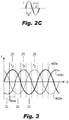
Fig. 2C is a graphical depiction of the transition between 2L and 3L mode in for a single hybrid power converter phase unit constructed in accordance with the present disclosure; -
Fig. 3 is a graphical depiction of the transition between 2L and 3L mode in a three-phase hybrid power conversion system constructed in accordance with the present disclosure; -
Fig. 4A is schematic depiction of another embodiment of a single hybrid power converter phase unit constructed in accordance with the present disclosure in the 2L mode, showing an active neutral pointed clamped converter (ANPC) topology where the inner switches form a half-bridge module and the outer switches form two half-bridge modules in series; and -
Fig. 4B is the single hybrid power converter phase unit ofFig. 4A in 3L mode. - Reference will now be made to the drawings wherein like reference numerals identify similar structural features or aspects of the subject disclosure. For purposes of explanation and illustration, and not limitation, a partial view of an embodiment of a system in accordance with the disclosure is shown in
Fig. 1 and is designated generally byreference character 100. Other embodiments of systems in accordance with the disclosure, or aspects thereof, are shown inFigs. 2A-4B and described below. The systems and methods described herein provide for a power monitoring relay system with overcurrent and frequency protection that acts to maintain the power quality, while providing independence and segregation from the main control/protection system. - As shown in
Fig. 1 , anelectrical system 100, e.g. an aircraft electrical system, includes a three-phase power conversion system 101 (e.g. which is also, in the context of certain aircraft systems, is called a motor controller) made of three hybrid powerconverter phase units 102a-102c and acontroller 105 in electrical communication with eachunit 102a-102c, or more phase units if needed. Communication betweencontroller 105 and various components is indicated schematically by broken lines. Aircraftelectrical system 100 includes a DC-DC converter 112 in electrical connection with hybrid powerconverter phase units 102a-102c to provide voltage to at least one of twovoltage inputs 104a and/or 104c. Aircraftelectrical system 100 includes abattery bank 114 in electrical connection with DC-DC converter 112 to provide power thereto. It is also contemplated thatbattery bank 114 could be a super capacitor bank. Both three-level (3L) and two-level (2L) converters are popular and widely used in motor-controllers, e.g. power conversion system, for electric propulsion, e.g. such as that used in electric vehicles, and aerospace systems. At a low-speed and high-torque operating condition, hybrid power converter phase units which could be embodied by existing three-level converters such as T-type converter units 102a-102c enable the hybrid operation of 2L and 3L converters sharing the same hardware, thereby reducing the thermal stress, among other things. - With reference now to
Figs. 1-3B , each hybrid powerconverter phase unit 102a-102c includes threeDC voltage inputs 104a-104c, anAC voltage output 106, a pair ofouter switches inner switches 110a-110b. The pair ofinner switches 110a-110b is between thevoltage inputs 104a and theouter switches 108a-108b. The pair ofouter switches 108a is between theDC voltage input 104a andAC voltage output 106.AC voltage output 106 is in electrical connection with a motor, not shown. Thecontroller 105 is in electrical communication withinner switches 110a-110b andouter switches 108a-108b for each hybrid powerconverter phase unit 102a-102c and is configured to selectively disable or enable, e.g. turn OFF or ON, theinner switches 110a-110b and controlouter switches 108a-108b accordingly. Theinner switches 110a-110b for a given power converter, e.g. 102a, are connected in series with one another. Theouter switches 108a-108b for a given power converter phase unit, e.g. 102a, are connected in series with one another. Theinner switches 110a-110b can be common source (CS) switches and form a CS module, as shown in the embodiment ofFig. 2A . - As shown in
Figs. 4A-4B , a powerconverter phase unit 202a has an active neutral pointed clamped (ANPC) topology whereinner switches outer switches devices converter phase unit 102a ofFigs. 2A-2B , whereouter switches 108a-108b form a half-bridge (HB) module. It is contemplated that other types of hybrid converter embodiments can be possible. Each pair of series-connecteddevices e.g. switch unit 202a can be used (similar to system 101). - With continued reference to
Figs. 4A-4B ,converter phase unit 202a can be used in conjunction with or in lieu of any ofconverter phase units 102a-102c insystem 101.Switches 210a-210b are shown in broken lines to indicate disabled (e.g. switched OFF) mode inFig. 4A , whereconverter 202a operates as a 2-level converter.Switches 210a-210b are shown in solid lines to indicate enabled (e.g. ON) mode inFig. 4B , where converter operates as a 3-level converter. This hybrid approach redistributes current stress, thereby alleviating thermal stress ofswitches 210a-210b. Acontroller 205 is in electrical communication withconverter unit 202a to provide similar commands/control ascontroller 105, as described above and below. Communication betweencontroller 205 and various components is indicated schematically by broken lines. Hybrid powerconverter phase unit 202a includes threeDC voltage inputs 204a-204c and anAC voltage output 206, similar toDC voltage inputs 104a-104c andAC voltage output 106. The disabled period/enabled period forunit 202a over a given angle span for a given current can be similar tounit 102a, described below. - As shown in
Figs. 2A and2C , in 2L mode, thecontroller 105 disables, e.g. turns OFF, the PWM signals ofinner switches 110a-110b (e.g. the CS switches) andconverter 102a operates as a typical 2L voltage source inverter. Thecontroller 105 disables all ofinner switches 110a-110b when a current (i) atvoltage output 106 is within a disable threshold, e.g. as shown in Equation 2 below.Switches 110a-110b are shown in broken lines to indicate disabled (e.g. switched OFF) mode inFig. 2A . As shown in the graphical depiction ofFig. 2C ,inner switches 110a-110b forconverter 102a are disabled over a given angle span θ when the current (i)atvoltage output 106 is proximate to the peak and/or valley. The disabled period is shown schematically by dashed lines inFig. 2C . During this period, theouter switches 108a-108b in the particular power converter phase unit are controlled as 2L half bridge converter. - As shown in
Figs. 2B-2C , thecontroller 105 is configured to enable theinner switches 1 10a-1 10b when the current (i) at thevoltage inputs 104a-104c are outside of a disable threshold, e.g. as shown in Equation 3 below.Switches 110a-110b are shown in solid lines to indicate enabled mode inFig. 2B . As shown in the graphical depiction ofFig. 2C ,inner switches 110a-110b forconverter 102a are enabled over a given angle span (180-0) for each half line cycle when the current (i) atvoltage output 106 is between to the peak and valley. The enabled period is shown schematically by solid lines inFig. 2C . This hybrid approach redistributes current stress, thereby alleviating thermal stress of CS modules (e.g. made up ofswitches 110a-110b). - In some embodiments, DC-
DC converter 112 provides further alleviation by lowering a DC link voltage at thevoltage inputs 104a-104c (orvoltage inputs 204a-204c ifconverter unit 202a is used). In these embodiments, the DC-DC converter 112 itself provides more control flexibility and functionalities to the overallelectrical system 100, such as charging/discharging of batteries or super-capacitors 114, fault-limiting (for certain topologies), providing for more control freedom toinner switches 110a-110b as the voltage or DC current of the DC energy input source has been already controlled by the DC-DC stage. Insystem 100, lowering the DC link voltage increases the modulation index ofpower conversion system 101 at low speed motor operation, thus reducing the current stress in the CS module (which includesinner switches 110a-110b) and shifts certain current loading to the HB module (which includesouter switches converter units 102a-102c and avoids extra cooling efforts forconverter units 102a-102c at low speed operation. By avoiding the additional cooling, additional thermal management and/or oversized power devices, the life of theelectrical system 100 can be increased and the power density of the motor controller can be increased. The estimated temperature reduction for the CS module is approximately 60 °C, for example. The reduced temperature allows for a more efficient and higher power density motor controller (e.g. switches 102a-102c). - A method includes selectively disabling or enabling inner switches, e.g.
inner switches converter phase unit e.g. controller e.g. voltage output 
Equation 1, where Iref is the peak value of the phase current reference which is the known variable in a motor controller, and θ is the angle span for each phase leg.
- If an absolute value of the measured current (i) is greater than or equal to the pre-determined value, as shown below by Equation 2, the controller disables the PWM signals of the inner switches and the hybrid power converter phase unit of this particular phase leg operates in 2L mode, as a typical 2L voltage source inverter.

Fig. 3 ) for each phase leg. As shown inFig. 3 , the mode-transition criterion is provided as below in Equation 3:
- As shown in
Fig. 3 , for a three phase hybrid power converter, e.g. apower conversion system 101 with three hybrid powerconverter phase units 102a-102c, each phase respectively switches to 2L mode in the vicinity of peak/valley current. Each phase is indicated graphically inFig. 3 ,line 402a is a depiction of the phase associated withconverter 102a,line 402b is a depiction of the phase associated withconverter 102b, andline 402c is a depiction of the phase associated withconverter 102c, for example. In a given line cycle [one peak and one valley], each phase has two 2L mode regions, making a total of six 2L regions. In between the 2L mode regions for a given phase, the converter operates in 3L mode. At any given time, only one converter phase unit, e.g. one phase leg, operates at 2L mode. In accordance with some embodiments, the maximum angle span of θmax for each region is 60 degrees. - In a T-type topology, e.g. that of
converter 102a,outer switches inner switches HB switches Figs. 4A-4B , in an ANPC topology,outer switches physical devices device Figs. 1-3 , under nominal operation of the T-type converter 102a, modulation index is high. HB switches 108a and 108b experience higher current loading thanCS switches CS switches HB switches HB switches CS switches - Those skilled in the art will readily appreciate that at certain speed and torque conditions, applying the hybrid mode alone may reduce the thermal stress of
CS switches HB switches 
- With continued reference to
Figs. 1-4B , embodiments of the present disclosure act to move the loading fromCS switches HB switches inner switches 210a-210b toouter switches inner switches 210a-210b high conduction loss and thermal stress. The line voltage is still within +/- Vdc/2, (the line-line dv/dt is for full Vdc), keeping the features of 3L converter. The HB switches 108a and 108b will have higher conduction loss and switching loss (both Vdc stress and higher current will contribute to higher switching loss). - As shown in
Fig. 1 , some embodiments of the present disclosure optionally include DC-DC converter 112, the DC link voltage atinputs DC converter 112. Additionally, using DC-DC converter results in reduced switching and total loss forHB switches - Those skilled in the art will readily appreciate that the embodiments of the present disclosure offer improved methods to control thermal stress as compared with traditional methods, e.g. oversized power module or cooling infrastructure. The methods and systems of the present disclosure, as described above and shown in the drawings, provide for electrical systems and methods to redistribute the current stress between the high stressed CS modules in the neutral path of the T-type converter to the near-idle HB power modules, thus alleviating the thermal stress of the CS modules. Moreover, the systems and methods described herein do not require hardware change or major software change, resulting in ease of implementation and low risk. While the apparatus and methods of the subject disclosure have been shown and described with reference to preferred embodiments, those skilled in the art will readily appreciate that changes and/or modifications may be made thereto without departing from the scope of the invention as defined by the claims.
Claims (15)
- A power conversion system, comprising:a hybrid power converter phase unit (102) including three voltage inputs (104), a voltage output(106), a pair of outer switches (108) between the voltage inputs and voltage output, and a pair of inner switches (110) between the voltage inputs and the outer switches; anda controller (105) in electrical communication with the inner and outer switches, wherein the controller is configured to selectively disable or enable the inner switches by switching the inner switches OFF or ON.
- The system as recited in claim 1, wherein the controller (105) is configured to disable the inner switches (110) when a current at the voltage inputs is within a disable threshold; and/or wherein the controller is configured to enable the inner switches when a current at the voltage inputs are outside of a disable threshold.
- The system as recited in claim 1 or 2, wherein the outer switches (108) form a half-bridge module, and optionally wherein the hybrid power converter phase unit has a T-type topology.
- The system as recited in claim 1 or 2, wherein the a hybrid power converter phase unit has an active neutral pointed clamped converter, ANPC, topology controlled by the controller, wherein each outer switch (208) itself includes a series-controlled half-bridge module.
- The system as recited in claim 1 or 2, wherein the inner switches form a common source module when the hybrid power converter has a T-type topology, and a half-bridge module when the hybrid power converter has a ANPC topology.
- The system as recited in any preceding claim, further comprising a second hybrid power converter phase unit and a third hybrid power converter phase unit to form a three-phase power converter, both in electrical communication with the controller.
- An electrical system, comprising:a power conversion system (101) including a hybrid power converter phase unit (102) and a controller (105) in electrical communication with the hybrid power converter phase unit, wherein the hybrid power converter phase unit includes three voltage inputs (104), a voltage output (106), a pair of outer switches (108) between the voltage inputs and voltage output, and a pair of inner switches (110) between the voltage inputs and the outer switches, wherein the controller is in electrical communication with the inner switches and is configured to selectively disable or enable the inner switches;a DC-DC converter (112) in electrical communication with the hybrid power converter phase unit to provide voltage to at least one of the negative or positive voltage inputs; anda battery bank (114) in electrical communication with the DC-DC converter to provide power thereto.
- The system as recited in claim 7, wherein the inner switches are common source switches.
- The system as recited in claim 7 or 8, wherein the power conversion system includes a second hybrid power converter phase unit and a third hybrid power converter phase unit, both in electrical communication with the controller.
- The system as recited in any preceding claim, wherein the inner switches are connected in series with one another.
- The system as recited in any preceding claim, wherein the outer switches are connected in series with one another.
- A method, comprising:
selectively disabling or enabling inner switches (110) in a hybrid power converter phase unit (102) with a controller (105) such that the hybrid power converter phase unit is a 3-level converter when the inner switches are ON and enabled in a 3-level mode and a 2-level converter when the inner switches are OFF and disabled in a 2-level mode. - The method of claim 12, wherein selectively disabling or enabling includes disabling or enabling PWM signals of the inner switches.
- The method of claim 12 or 13, wherein selectively disabling or enabling includes enabling the inner switches if an absolute value of a measured current is less than a pre-determined value, and/or wherein selectively disabling or enabling includes disabling the inner switches if an absolute value of a measured current is greater than a pre-determined value.
- The method of claim 12, 13 or 14, further comprising series-controlling outer switches in the hybrid power converter phase unit to withstand a full DC voltage in the 2-level mode without overvoltage stress concern, wherein the hybrid power converter phase unit has an ANPC topology.
Applications Claiming Priority (1)
| Application Number | Priority Date | Filing Date | Title |
|---|---|---|---|
| US16/827,528 US11218086B2 (en) | 2020-03-23 | 2020-03-23 | Power conversion systems and methods |
Publications (1)
| Publication Number | Publication Date |
|---|---|
| EP3886308A1 true EP3886308A1 (en) | 2021-09-29 |
Family
ID=75203080
Family Applications (1)
| Application Number | Title | Priority Date | Filing Date |
|---|---|---|---|
| EP21164417.4A Pending EP3886308A1 (en) | 2020-03-23 | 2021-03-23 | Power conversion systems and methods |
Country Status (2)
| Country | Link |
|---|---|
| US (1) | US11218086B2 (en) |
| EP (1) | EP3886308A1 (en) |
Families Citing this family (10)
| Publication number | Priority date | Publication date | Assignee | Title |
|---|---|---|---|---|
| CN113826319B (en) * | 2019-05-16 | 2024-07-05 | 日立三菱水力株式会社 | Secondary excitation power generation electric device |
| CN112968624A (en) * | 2021-03-17 | 2021-06-15 | 山特电子(深圳)有限公司 | Bidirectional DC-AC conversion circuit and starting method thereof |
| GB2616645B (en) * | 2022-03-16 | 2025-04-09 | Yasa Ltd | A voltage converter and method of converting voltage |
| CN116094356A (en) * | 2023-01-03 | 2023-05-09 | 国电南瑞科技股份有限公司 | Mixed modulation method of ANPC three-level converter |
| US12500540B2 (en) | 2023-11-03 | 2025-12-16 | GM Global Technology Operations LLC | System for mutual inductance cancellation for H-type multilevel converters |
| US12397652B2 (en) | 2023-11-03 | 2025-08-26 | GM Global Technology Operations LLC | System for mutual inductance cancellation for X-type multilevel converters |
| US12291104B1 (en) | 2023-11-03 | 2025-05-06 | GM Global Technology Operations LLC | System for mutual inductance cancellation for T-type multilevel converters |
| US20250309779A1 (en) * | 2024-03-27 | 2025-10-02 | GM Global Technology Operations LLC | System and method for mutual inductance cancellation for two-level converters |
| WO2025217128A1 (en) * | 2024-04-09 | 2025-10-16 | Texas Instruments Incorporated | Adaptive control for multi-level converters |
| DE102024205614A1 (en) | 2024-05-15 | 2025-11-20 | Schaeffler Technologies AG & Co. KG | Multilevel converter with phase-individual, capacitively generated reference potential |
Citations (4)
| Publication number | Priority date | Publication date | Assignee | Title |
|---|---|---|---|---|
| US20040145338A1 (en) * | 2001-12-26 | 2004-07-29 | Makoto Nakamura | Electric load apparatus electric load controlling method and computer readable recording medium recording program for causing computer to execute control of electric load |
| EP2611021A1 (en) * | 2010-08-23 | 2013-07-03 | Toshiba Mitsubishi-Electric Industrial Systems Corporation | Electricity conversion device |
| US20140233290A1 (en) * | 2013-02-19 | 2014-08-21 | Robert Bosch Gmbh | Inverter system and driving method for an inverter system |
| US20190238062A1 (en) * | 2018-01-31 | 2019-08-01 | Gan Systems Inc. | Enhanced performance hybrid three-level inverter/rectifier |
Family Cites Families (9)
| Publication number | Priority date | Publication date | Assignee | Title |
|---|---|---|---|---|
| US7688048B2 (en) * | 2007-02-21 | 2010-03-30 | American Power Conversion Corporation | 3-phase high power UPS |
| DE102009047936A1 (en) * | 2009-10-01 | 2011-04-07 | Dr. Johannes Heidenhain Gmbh | Method of operating an inverter and inverter |
| US8942019B2 (en) * | 2011-11-01 | 2015-01-27 | Fairchild Korea Semiconductor Ltd. | Current vector controlled deadtime for multilevel inverters |
| US9236828B1 (en) | 2014-07-03 | 2016-01-12 | Rockwell Automation Technologies, Inc. | Methods and power conversion system control apparatus to control IGBT junction temperature at low speed |
| DE102017203233A1 (en) * | 2017-02-28 | 2018-08-30 | Siemens Aktiengesellschaft | Modular inverter |
| EP3659080A4 (en) | 2017-07-28 | 2021-04-21 | Nuro, Inc. | SYSTEM AND MECHANISM FOR INCENTIVE SELLING OF PRODUCTS ON AUTONOMOUS VEHICLES |
| US10770987B2 (en) | 2018-05-11 | 2020-09-08 | Hamilton Sunstrand Corporation | Motor drive architecture for variable frequency alternating current loads |
| US20200028448A1 (en) * | 2018-07-18 | 2020-01-23 | Hamilton Sundstrand Corporation | H-type multilevel power converter |
| US11476671B2 (en) * | 2019-10-22 | 2022-10-18 | Delta Electronics (Shanghai) Co., Ltd. | Wind power converting device |
-
2020
- 2020-03-23 US US16/827,528 patent/US11218086B2/en active Active
-
2021
- 2021-03-23 EP EP21164417.4A patent/EP3886308A1/en active Pending
Patent Citations (4)
| Publication number | Priority date | Publication date | Assignee | Title |
|---|---|---|---|---|
| US20040145338A1 (en) * | 2001-12-26 | 2004-07-29 | Makoto Nakamura | Electric load apparatus electric load controlling method and computer readable recording medium recording program for causing computer to execute control of electric load |
| EP2611021A1 (en) * | 2010-08-23 | 2013-07-03 | Toshiba Mitsubishi-Electric Industrial Systems Corporation | Electricity conversion device |
| US20140233290A1 (en) * | 2013-02-19 | 2014-08-21 | Robert Bosch Gmbh | Inverter system and driving method for an inverter system |
| US20190238062A1 (en) * | 2018-01-31 | 2019-08-01 | Gan Systems Inc. | Enhanced performance hybrid three-level inverter/rectifier |
Also Published As
| Publication number | Publication date |
|---|---|
| US20210297009A1 (en) | 2021-09-23 |
| US11218086B2 (en) | 2022-01-04 |
Similar Documents
| Publication | Publication Date | Title |
|---|---|---|
| US11218086B2 (en) | Power conversion systems and methods | |
| US8297389B2 (en) | Load driving system and electric vehicle using the system | |
| US20120069604A1 (en) | Compact power converter with high efficiency in operation | |
| US20130285456A1 (en) | Controllable energy store and method for operating a controllable energy store | |
| US11267351B2 (en) | Power conversion device | |
| US12046988B2 (en) | Power supply system and moving body | |
| EP4099552B1 (en) | Power conversion device | |
| CN114336523A (en) | Active short circuit control method, motor controller and motor control system | |
| JP3677048B2 (en) | Method for processing pulse width modulated wave and apparatus applying this method | |
| Chiasson et al. | Conditions for capacitor voltage regulation in a five-level cascade multilevel inverter: Application to voltage-boost in a PM drive | |
| CN110089022A (en) | Controller for motor and electric vehicle | |
| CN112564121A (en) | Topology reconstruction and function multiplexing oriented series-connection type power electronic equipment and control method | |
| KR102453339B1 (en) | Controlling circuit for multilevel inverter and controlling method thereof | |
| KR20240095238A (en) | Power converter control method using variable switching frequency | |
| US11855555B2 (en) | Control device for an inverter, inverter for a vehicle, vehicle and method of operating an inverter | |
| US12202358B2 (en) | Power supply system and moving body | |
| US20250007423A1 (en) | Power converter, electrical machine unit and method for current conversion | |
| EP4383550A1 (en) | Power conversion apparatus and control apparatus for same | |
| US20220393613A1 (en) | Power supply system and moving body | |
| CN113258855B (en) | Redundant motor drives | |
| US20240429808A1 (en) | Arrangement for Current Sharing of Parallel-Connected Converters | |
| US20250001876A1 (en) | Voltage switching of an electric motor | |
| JP7460508B2 (en) | Power Conversion Equipment | |
| Wu et al. | Modulation Schemes for a 36MVA Press-Pack IGBT Converter under Interleaved Operation | |
| US20250233528A1 (en) | Control device for multi-level inverter, program, and multi-level inverter |
Legal Events
| Date | Code | Title | Description |
|---|---|---|---|
| PUAI | Public reference made under article 153(3) epc to a published international application that has entered the european phase |
Free format text: ORIGINAL CODE: 0009012 |
|
| STAA | Information on the status of an ep patent application or granted ep patent |
Free format text: STATUS: THE APPLICATION HAS BEEN PUBLISHED |
|
| AK | Designated contracting states |
Kind code of ref document: A1 Designated state(s): AL AT BE BG CH CY CZ DE DK EE ES FI FR GB GR HR HU IE IS IT LI LT LU LV MC MK MT NL NO PL PT RO RS SE SI SK SM TR |
|
| STAA | Information on the status of an ep patent application or granted ep patent |
Free format text: STATUS: REQUEST FOR EXAMINATION WAS MADE |
|
| 17P | Request for examination filed |
Effective date: 20220329 |
|
| RBV | Designated contracting states (corrected) |
Designated state(s): AL AT BE BG CH CY CZ DE DK EE ES FI FR GB GR HR HU IE IS IT LI LT LU LV MC MK MT NL NO PL PT RO RS SE SI SK SM TR |
|
| STAA | Information on the status of an ep patent application or granted ep patent |
Free format text: STATUS: EXAMINATION IS IN PROGRESS |
|
| 17Q | First examination report despatched |
Effective date: 20230127 |