EP3886300A1 - Plate stacked body, stacked iron core, and motor - Google Patents
Plate stacked body, stacked iron core, and motor Download PDFInfo
- Publication number
- EP3886300A1 EP3886300A1 EP21153507.5A EP21153507A EP3886300A1 EP 3886300 A1 EP3886300 A1 EP 3886300A1 EP 21153507 A EP21153507 A EP 21153507A EP 3886300 A1 EP3886300 A1 EP 3886300A1
- Authority
- EP
- European Patent Office
- Prior art keywords
- stator core
- plates
- adhesive
- thickness direction
- plate
- Prior art date
- Legal status (The legal status is an assumption and is not a legal conclusion. Google has not performed a legal analysis and makes no representation as to the accuracy of the status listed.)
- Withdrawn
Links
Images


Classifications
-
- H—ELECTRICITY
- H02—GENERATION; CONVERSION OR DISTRIBUTION OF ELECTRIC POWER
- H02K—DYNAMO-ELECTRIC MACHINES
- H02K15/00—Processes or apparatus specially adapted for manufacturing, assembling, maintaining or repairing of dynamo-electric machines
- H02K15/02—Processes or apparatus specially adapted for manufacturing, assembling, maintaining or repairing of dynamo-electric machines of stator or rotor bodies
-
- H—ELECTRICITY
- H02—GENERATION; CONVERSION OR DISTRIBUTION OF ELECTRIC POWER
- H02K—DYNAMO-ELECTRIC MACHINES
- H02K1/00—Details of the magnetic circuit
- H02K1/06—Details of the magnetic circuit characterised by the shape, form or construction
- H02K1/12—Stationary parts of the magnetic circuit
- H02K1/16—Stator cores with slots for windings
-
- H—ELECTRICITY
- H01—ELECTRIC ELEMENTS
- H01F—MAGNETS; INDUCTANCES; TRANSFORMERS; SELECTION OF MATERIALS FOR THEIR MAGNETIC PROPERTIES
- H01F3/00—Cores, Yokes, or armatures
- H01F3/02—Cores, Yokes, or armatures made from sheets
-
- H—ELECTRICITY
- H01—ELECTRIC ELEMENTS
- H01F—MAGNETS; INDUCTANCES; TRANSFORMERS; SELECTION OF MATERIALS FOR THEIR MAGNETIC PROPERTIES
- H01F41/00—Apparatus or processes specially adapted for manufacturing or assembling magnets, inductances or transformers; Apparatus or processes specially adapted for manufacturing materials characterised by their magnetic properties
- H01F41/02—Apparatus or processes specially adapted for manufacturing or assembling magnets, inductances or transformers; Apparatus or processes specially adapted for manufacturing materials characterised by their magnetic properties for manufacturing cores, coils, or magnets
- H01F41/0206—Manufacturing of magnetic cores by mechanical means
- H01F41/0233—Manufacturing of magnetic circuits made from sheets
-
- H—ELECTRICITY
- H02—GENERATION; CONVERSION OR DISTRIBUTION OF ELECTRIC POWER
- H02K—DYNAMO-ELECTRIC MACHINES
- H02K1/00—Details of the magnetic circuit
- H02K1/06—Details of the magnetic circuit characterised by the shape, form or construction
-
- H—ELECTRICITY
- H02—GENERATION; CONVERSION OR DISTRIBUTION OF ELECTRIC POWER
- H02K—DYNAMO-ELECTRIC MACHINES
- H02K1/00—Details of the magnetic circuit
- H02K1/06—Details of the magnetic circuit characterised by the shape, form or construction
- H02K1/22—Rotating parts of the magnetic circuit
- H02K1/27—Rotor cores with permanent magnets
- H02K1/2706—Inner rotors
- H02K1/272—Inner rotors the magnetisation axis of the magnets being perpendicular to the rotor axis
- H02K1/2726—Inner rotors the magnetisation axis of the magnets being perpendicular to the rotor axis the rotor consisting of a single magnet or two or more axially juxtaposed single magnets
- H02K1/2733—Annular magnets
-
- H—ELECTRICITY
- H02—GENERATION; CONVERSION OR DISTRIBUTION OF ELECTRIC POWER
- H02K—DYNAMO-ELECTRIC MACHINES
- H02K1/00—Details of the magnetic circuit
- H02K1/06—Details of the magnetic circuit characterised by the shape, form or construction
- H02K1/22—Rotating parts of the magnetic circuit
- H02K1/27—Rotor cores with permanent magnets
- H02K1/2706—Inner rotors
- H02K1/272—Inner rotors the magnetisation axis of the magnets being perpendicular to the rotor axis
- H02K1/274—Inner rotors the magnetisation axis of the magnets being perpendicular to the rotor axis the rotor consisting of two or more circumferentially positioned magnets
-
- H—ELECTRICITY
- H02—GENERATION; CONVERSION OR DISTRIBUTION OF ELECTRIC POWER
- H02K—DYNAMO-ELECTRIC MACHINES
- H02K15/00—Processes or apparatus specially adapted for manufacturing, assembling, maintaining or repairing of dynamo-electric machines
- H02K15/12—Impregnating, moulding insulation, heating or drying of windings, stators, rotors or machines
-
- H—ELECTRICITY
- H02—GENERATION; CONVERSION OR DISTRIBUTION OF ELECTRIC POWER
- H02K—DYNAMO-ELECTRIC MACHINES
- H02K2201/00—Specific aspects not provided for in the other groups of this subclass relating to the magnetic circuits
- H02K2201/09—Magnetic cores comprising laminations characterised by being fastened by caulking
Definitions
- the present invention relates to a plate stacked body, a stacked iron core, and a motor.
- Patent Literature 1 discloses a stacked iron core in which a plurality of divided stacked iron cores, obtained by stacking iron core pieces each having a back yoke portion and a tooth portion, are connected in an annular shape.
- the divided stacked iron core of Patent Literature 1 has a groove at the tip of the tooth portion.
- An adhesive is injected into the groove in a state where the back yoke portion of the divided stacked iron core is pressed in the stacking direction to form a gap on the tip end side of the tooth portion.
- the adhesive injected in the groove soaks into the gap between the plurality of tooth portions in the divided stacked iron core.
- the pressure applied to the back yoke portion in the stacking direction is stopped, and the plurality of tooth portions are returned to a state without the gap. Then, when the adhesive is cured, a divided stacked iron core in which a plurality of iron core pieces are joined by the adhesive is obtained.
- Patent Literature1 JP 2015-136228 A
- the adhesive may not provide sufficient bonding strength between the plates, or the adhesive may adhere to an unnecessary portion of the plate stacked body to cause functional deterioration.
- An object of the present invention is to provide a plate stacked body enabling a plurality of plates stacked in the thickness direction to be joined together with an adhesive with sufficient joining strength without impairing the function.
- a plate stacked body includes a plurality of plates in a disk shape stacked in a thickness direction and constituting a stacked body in a columnar shape having a filled portion extending in an axial direction, and an adhesive portion in a pillar shape including an adhesive contained in the filled portion and bonding the plurality of plates together in the axial direction.
- a part of inner surfaces of the filled portion is configured of surfaces in the thickness direction of the plurality of plates exposed in the filled portion.
- the adhesive portion has an axial adhesive portion that adheres in the axial direction to the surfaces in the thickness direction of the plurality of plates exposed in the filled portion.
- a stacked iron core according to one embodiment of the present invention is configured of the above-mentioned plate stacked body.
- Each of the plurality of plates constituting the plate stacked body is an electromagnetic steel plate.
- a motor includes a stator and a rotor. At least one of the stator and the rotor has a stacked iron core in which electromagnetic steel plates are stacked in the thickness direction.
- the stacked iron core is configured of the above-mentioned plate stacked body.
- a plurality of plates stacked in the thickness direction can be joined together with an adhesive with sufficient joining strength without impairing the function.
- a direction parallel to the central axis P of a rotor 2 is referred to as an "axial direction”
- a direction orthogonal to the central axis P is referred to as a “radial direction”
- a direction along an arc with the central axis P as the center is referred to as a "circumferential direction”.
- axial direction a direction parallel to the central axis P of a rotor 2
- radial direction a direction orthogonal to the central axis P
- a direction along an arc with the central axis P as the center is referred to as a "circumferential direction”.
- the expressions such as “fixed”, “connected”, “joined” and “attached” are not limited to the case where the members are directly fixed or the like to each other. It also includes the case where it is fixed or the like via another member. That is, in the following description, the expression such as fixation includes the meaning of direct and indirect fixation or the like between members.
- Fig. 1 shows a schematic configuration of the motor 1 according to the embodiment of the present invention.
- the motor 1 includes a rotor 2, a stator 3, and a housing 4.
- the rotor 2 rotates about the central axis P with respect to the stator 3.
- the motor 1 is a so-called inner rotor type motor in which the rotor 2 is rotatably positioned about the central axis P in the tubular stator 3.
- the rotor 2 includes a shaft 20, a rotor core 21, and a magnet 22.
- the rotor 2 is located radially inside the stator 3 and is rotatable with respect to the stator 3.
- the rotor core 21 has a cylindrical shape extending along the central axis P.
- the shaft 20 extending along the central axis P is fixed to the rotor core 21 in a state of penetrating in the axial direction.
- the rotor core 21 rotates with the shaft 20.
- a plurality of magnets 22 are located on the outer peripheral surface of the rotor core 21 at predetermined intervals in the circumferential direction.
- the magnets 22 may be located inside the rotor core 21. Further, the magnets 22 may be a ring magnet connected in the circumferential direction.
- the stator 3 is housed in the housing 4.
- the stator 3 has a tubular shape.
- the rotor 2 is positioned radially inside the stator 3. That is, the stator 3 is positioned so as to face the rotor 2 in the radial direction.
- the rotor 2 is positioned radially inside the stator 3 so as to be rotatable about the central axis P.
- the stator 3 includes a stator core 31 and a stator coil 32.
- Fig. 2 is a perspective view showing a schematic configuration of the stator core 31.
- the stator core 31 has a cylindrical shape extending in the axial direction. That is, the stator core 31 has a circular through hole 31a, a plurality of stator core teeth 31b, and an annular back yoke 31c. The rotor core 21 and the magnets 22 of the rotor 2 are positioned in the through hole 31a.
- the plurality of stator core teeth 31b extend radially inward from the inner peripheral side of the back yoke 31c.
- the inner peripheral ends of the plurality of stator core teeth 31b form the peripheral edge of the through hole 31a.
- a stator coil 32 is wound around the plurality of stator core teeth 31b.
- the stator core 31 has a plurality of groove-shaped filled portions 34 extending in the axial direction and a plurality of adhesive portions 35 extending in the filled portion 34 in the axial direction, on the outer peripheral side of the back yoke 31c.
- the plurality of filled portions 34 are located on the outer peripheral side of the back yoke 31c at equal intervals in the circumferential direction. Therefore, the plurality of adhesive portions 35 are also located on the outer peripheral side of the back yoke 31c at equal intervals in the circumferential direction.
- the plurality of adhesive portions 35 join a plurality of stator core plates 33, described later, in the axial direction.
- the stator core 31 has a plurality of stator core plates 33 formed in a predetermined shape and stacked in the thickness direction.
- Fig. 3 is a plan view showing an example of the stator core plate 33.
- the stator core plate 33 is a disk-shaped electromagnetic steel plate.
- the stator core plate 33 corresponds to a disk-shaped plate of the present invention.
- the stator core plate 33 has a circular hole portion 33a, a plurality of tooth portions 33b, and an annular yoke portion 33c. Each of the plurality of tooth portions 33b projects radially inward from the inner peripheral side of the yoke portion 33c.
- stator core plates 33 are stacked in the thickness direction to form the stator core 31. Therefore, the hole portion 33a of the stator core plate 33 constitutes a part of the through hole 31a of the stator core 31. Similarly, the tooth portion 33b of the stator core plate 33 constitutes a part of the stator core tooth 31b of the stator core 31. Further, the yoke portion 33c of the stator core plate 33 constitutes a part of the back yoke 31c of the stator core 31.
- the yoke portion 33c has a plurality of notches 33d on the outer peripheral side.
- the plurality of notches 33d have a rectangular shape when viewed in the axial direction.
- the plurality of notches 33d form a part of the filled portion 34 of the stator core 31.
- the plurality of notches 33d may have another shape such as a circular shape or a triangular shape when viewed in the axial direction.
- the stator core plate 33 is obtained by punching a strip-shaped electromagnetic steel plate into a disk shape with a die.
- a state in which a plurality of stator core plates 33 are not joined by the adhesive portion 35 is referred to as a stacked body.
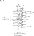
- Fig. 4 is an enlarged view of the filled portion 34 and the adhesive portion 35 of the stator core 31 as viewed from the direction orthogonal to the central axis P.
- Fig. 5 is an enlarged perspective view of the filled portion 34 of the stator core 31.
- the filled portion 34 of the stator core 31 is a groove extending in the axial direction on the outer peripheral side of the back yoke 31c of the stator core 31.
- the filled portion 34 is configured of the notches 33d located on the outer peripheral side of the yoke portions 33c of the plurality of stator core plates 33 stacked in the thickness direction.
- the filled portion 34 has a plurality of inner surfaces 34a extending in the axial direction.
- the filled portion 34 has three inner surfaces 34a configured of three end faces constituting each of the notches 33d in the plurality of stator core plates 33.
- the width of the filled portion 34 in the circumferential direction differs between the adjacent stator core plates 33 in the axial direction of the stator core 31. That is, in the plurality of stator core plates 33 constituting the stator core 31, the lengths of the plurality of notches 33d in the circumferential direction are different in the stator core plates 33 adjacent to each other in the thickness direction.
- the plurality of stator core plates 33 constituting the stator core 31 include a first stator core plate 331 having a notch in which the length in the circumferential direction is short and a second stator core plate 332 having a notch in which the length in the circumferential direction is long.
- the first stator core plate 331 and the second stator core plate 332 are alternately stacked in the thickness direction. As a result, the width of the filled portion 34 differs between the adjacent stator core plates 33.
- the notch of the first stator core plate 331 is denoted by a reference numeral 331a
- the notch of the second stator core plate 332 is denoted by a reference numeral 332a. That is, the notches 33d of the stator core plates 33 include the notch 331a of the first stator core plate 331 and the notch 332a of the second stator core plate 332.
- the circumferential length of the notch 332a of the second stator core plate 332 is longer than the circumferential length of the notch 331a of the first stator core plate 331.
- a surface 331b of the peripheral portion of the notch 331a in the first stator core plate 331 is exposed in the filled portion 34. That is, a part of the surface 331b in the thickness direction of the first stator core plate 331 is exposed in the filled portion 34 and constitutes a part of the inner surface 34a of the filled portion 34. In the filled portion 34, the surfaces 331b in the thickness direction of the plurality of first stator core plates 331 are exposed.
- the first stator core plates 331 are located at both ends in the axial direction.
- the first stator core plates 331 are located at both ends in the axial direction of the stator core 31, but the second stator core plates 332 may be located at both ends in the axial direction of the stator core 31.
- the adhesive portion 35 is obtained by curing the adhesive contained in the filled portion 34 having the above-described configuration. That is, the adhesive portion 35 is composed of an adhesive.
- the adhesive for example, an adhesive having a viscosity that does not flow out from the filled portion 34 when contained in the filled portion 34 is preferable.
- the adhesive is preferably a thermoplastic adhesive. As described above, by using a thermoplastic adhesive, it is possible to suppress deformation of the stator core plate 33 and the like because heating is not required when the adhesive is cured.
- thermosetting adhesive may be used as the adhesive because the influence of heat on the stator core plate is small.
- the adhesive portion 35 in a pillar shape for bonding the plurality of stator core plates 33 in the axial direction is formed in the filled portion 34.
- a part of the inner surface of the filled portion 34 is configured of the surface 331b in the thickness direction constituting the peripheral portion of the notch 33d in the first stator core plate 331. Therefore, the adhesive portion 35 bonds and fixes the surfaces 331b in the thickness direction of the first stator core plates 331, which constitute a part of the inner surface of the filled portion 34.
- the surfaces 331b in the thickness direction of the plurality of first stator core plates 331 located at predetermined intervals in the filled portion 34 of the stator core 31 can be bonded and fixed in the axial direction by the adhesive portion 35.
- the adhesive portion 35 has an axial adhesive portion 35a that bonds the surfaces 331b in the thickness direction of the first stator core plates 331 exposed in the filled portion 34, in the axial direction of the stator core 31.
- the axial adhesive portion 35a is located between the surfaces 331b in the thickness direction of the first stator core plates 331 adjacent to each other in the stacking direction, in the filled portion 34.
- the first stator core plates 331 are located at both ends of the stator core 31 in the axial direction. Therefore, as described above, by bonding the surfaces 331b in the thickness direction of the first stator core plates 331 in the axial direction by the axial adhesive portion 35a, it is possible to join the plurality of stator core plates 33 constituting the stator core 31 more firmly in the axial direction.
- the adhesive portion 35 is formed by filling the filled portion 34 with an adhesive and curing the adhesive, in the shape of the adhesive portion 35, the circumferential dimensions are different between the adjacent stator core plates 33 when viewed in the direction orthogonal to the central axis P of the stator core 31.
- the plurality of stator core plates 33 can be more firmly joined in the axial direction by the adhesive portion 35.
- the stator core 31 of the present embodiment is a plate stacked body formed by stacking a plurality of stator core plates 33 in the thickness direction.
- the stator core 31 includes a plurality of disk-shaped stator core plates 33 that are stacked in the thickness direction and constitute a columnar stacked body having the filled portion 34 extending in the axial direction, and the adhesive portion 35 in a pillar shape configured of an adhesive contained in the filled portion 34 and bonds the plurality of stator core plates 33 in the axial direction.
- a part of the inner surface of the filled portion 34 is configured of the surface 331b in the thickness direction of the first stator core plate 331 exposed in the filled portion 34.
- the adhesive portion 35 has the axial adhesive portion 35a that adheres in the axial direction to the surface 331b in the thickness direction of the first stator core plate 331 exposed in the filled portion 34.
- the radial size of the columnar stacked body configured of the plurality of stator core plates 33 stacked in the thickness direction is small, when the surfaces of the plurality of stator core plates 33 in the thickness direction are bonded to each other with an adhesive, it is difficult to control the adhesive applying position. Even in that case, since the adhesive portion 35 in the pillar shape extending in the axial direction has the axial adhesive portion 35a as described above, the plurality of stator core plates 33 can be firmly joined in the axial direction.
- the plurality of stator core plates 33 stacked in the thickness direction can be firmly joined in the axial direction by using an adhesive.
- the surfaces 331b in the thickness direction of at least two first stator core plates 331 located apart from each other in the axial direction is exposed in the filled portion 34.
- the axial adhesive portion 35a is configured of the adhesive applied to the surfaces 331b in the thickness direction of the at least two first stator core plates 331.
- the axial adhesive portion 35a is configured of the adhesive applied to the surfaces 331b in the thickness direction exposed in the filled portion 34 in at least two first stator core plates 331 located apart from each other in the axial direction, a plurality of stator core plates 33 stacked in the thickness direction can be more firmly joined in the axial direction.
- the first stator core plates 331 in which the surfaces 331b in the thickness direction are exposed in the filled portion 34 are located at both ends in the axial direction of the stator core 31.
- the axial adhesive portion 35a adheres to the surfaces 331b in the thickness direction of the first stator core plates 331 located at both ends in the axial direction of the stator core 31.
- the plurality of stator core plates 33 stacked in the thickness direction can be joined more firmly in the axial direction.
- the inner surface of the filled portion 34 includes a plurality of inner surfaces 34a extending in the axial direction.
- a part of the plurality of inner surfaces 34a is configured of the surface 331b in the thickness direction of the first stator core plate 33 exposed in the filled portion 34.
- the axial adhesive portion 35a is composed of an adhesive applied to the surfaces 331b in the thickness direction of the first stator core plates 331 exposed in the filled portion 34 on the plurality of inner surfaces 34a.
- the plurality of stator core plates 33 stacked in the thickness direction can be joined more firmly in the axial direction by the axial adhesive portion 35a adhering to the surfaces 331b in the thickness direction of the first stator core plates 331 exposed in the filled portion 34 on the plurality of inner surfaces 34a of the filled portion 34.
- the filled portion 34 is a groove located on the outer peripheral surface of the stator core 31 and extending in the axial direction.
- the plurality of stator core plates 33 stacked in the thickness direction can be joined in the axial direction by the adhesive portion 35 composed of the adhesive contained in the filled portion 34 located on the outer peripheral surface.
- the stator core plate 33 constituting the stator core 31 is an electromagnetic steel plate.
- stator core 31 in which the electromagnetic steel plates are stacked in the thickness direction is obtained. Even in the case of the small stator core 31, the stator core plates 33 can be firmly joined in the axial direction by the adhesive.
- the motor 1 of the present embodiment includes the stator 3 and the rotor 2. At least one of the stator 3 and the rotor 2 has a stacked iron core in which electromagnetic steel plates are stacked in the thickness direction.
- the stacked iron core is configured of a plate stacked body having the same configuration as that of the stator core 31 of the present embodiment.
- the configuration of the present embodiment can be applied to the stacked iron core of at least one of the stator 3 and the rotor 2 of the motor 1. Therefore, the stacked iron core of a small motor can be firmly joined in the axial direction with an adhesive.
- the present embodiment is not limited to the above-described embodiment, and the above-described embodiment can be appropriately modified and implemented within a range that does not deviate from the gist thereof.
- the configuration of the stator core 31 has been described.
- the stacked structure as described in the above embodiment may be applied to a configuration other than a stator core as long as it is a plate stacked body in which plates are stacked in the thickness direction.
- the stacked structure as described in the above embodiment may be applied to a rotor core.
- the plate stacked body includes a groove-shaped filled portion located on the outer peripheral surface and extending in the axial direction, and an adhesive portion configured of an adhesive in the filled portion, as in the embodiment.
- the first stator core plate 331 with the notch 331a and the second stator core plate 332 with the notch 332a having a circumferential length that is longer than that of the notch 331a are alternately located in the thickness direction.
- the first stator core plate and the second stator core plate may be arranged in the thickness direction in any way as long as a plurality of stator core plates constituting the stator core include a plurality of first stator core plates.
- the first stator core plates are located at both ends of the stator core 31 in the axial direction as in the above embodiment.
- the plurality of stator core plates 33 include the first stator core plate 331 with the notch 331a, and the second stator core plate 332 with the notch 332a having a circumferential length that is longer than that of the notch 331a.
- the plurality of stator core plates may include a plurality of types of stator core plates having different notch shapes and having surfaces in the thickness direction of some of the stator core plates exposed in the filled portion.
- the stator core plate 33 is an electromagnetic steel plate.
- the stator core plate may be a plate member other than an electromagnetic steel plate.
- stator core plate 33 As an example of the stator core plate 33, the examples shown in Figs. 2 and 3 are given. However, the structure of the stator core plate may be other than those shown in Figs. 2 and 3 .
- the filled portion 34 and the adhesive portion 35 included in the stator core 31 are given.
- the structures of the filled portion and the adhesive portion may be other than those shown in Figs. 2 and 4 .
- the motor is a so-called permanent magnet motor.
- the rotor has a magnet.
- the motor 1 may be a motor without a magnet, such as an induction machine, a reluctance motor, a switched reluctance motor, or a winding field type motor.
- the present invention is applicable to a plate stacked body in which a plurality of disk-shaped plates stacked in the thickness direction are joined with an adhesive.
Landscapes
- Engineering & Computer Science (AREA)
- Power Engineering (AREA)
- Manufacturing & Machinery (AREA)
- Iron Core Of Rotating Electric Machines (AREA)
Abstract
Description
- The present invention relates to a plate stacked body, a stacked iron core, and a motor.
- A plate stacked body obtained by joining a plurality of plates in the axial direction in a state of being stacked in the thickness direction is known. As such a plate stacked body, for example,
Patent Literature 1 discloses a stacked iron core in which a plurality of divided stacked iron cores, obtained by stacking iron core pieces each having a back yoke portion and a tooth portion, are connected in an annular shape. - The divided stacked iron core of
Patent Literature 1 has a groove at the tip of the tooth portion. An adhesive is injected into the groove in a state where the back yoke portion of the divided stacked iron core is pressed in the stacking direction to form a gap on the tip end side of the tooth portion. The adhesive injected in the groove soaks into the gap between the plurality of tooth portions in the divided stacked iron core. - Before the adhesive is cured, the pressure applied to the back yoke portion in the stacking direction is stopped, and the plurality of tooth portions are returned to a state without the gap. Then, when the adhesive is cured, a divided stacked iron core in which a plurality of iron core pieces are joined by the adhesive is obtained.
- Patent Literature1:
JP 2015-136228 A - As described above, when a plurality of iron core pieces are fixed with an adhesive in a stacked state, it is easy to control the range of bonding by the adhesive if the plate stacked body is relatively large in size.
- However, in the case of a small plate stacked body, it is difficult to bond the stacked plates together with an adhesive only at necessary portions. Therefore, in the case of a small plate stacked body, the adhesive may not provide sufficient bonding strength between the plates, or the adhesive may adhere to an unnecessary portion of the plate stacked body to cause functional deterioration.
- On the other hand, even for a small plate stacked body, there is a demand for a configuration in which the plates made in a stacked body can be joined together with sufficient strength only at portions that need to be bonded with an adhesive.
- An object of the present invention is to provide a plate stacked body enabling a plurality of plates stacked in the thickness direction to be joined together with an adhesive with sufficient joining strength without impairing the function.
- A plate stacked body according to one embodiment of the present invention includes a plurality of plates in a disk shape stacked in a thickness direction and constituting a stacked body in a columnar shape having a filled portion extending in an axial direction, and an adhesive portion in a pillar shape including an adhesive contained in the filled portion and bonding the plurality of plates together in the axial direction. A part of inner surfaces of the filled portion is configured of surfaces in the thickness direction of the plurality of plates exposed in the filled portion. The adhesive portion has an axial adhesive portion that adheres in the axial direction to the surfaces in the thickness direction of the plurality of plates exposed in the filled portion.
- A stacked iron core according to one embodiment of the present invention is configured of the above-mentioned plate stacked body. Each of the plurality of plates constituting the plate stacked body is an electromagnetic steel plate.
- A motor according to one embodiment of the present invention includes a stator and a rotor. At least one of the stator and the rotor has a stacked iron core in which electromagnetic steel plates are stacked in the thickness direction. The stacked iron core is configured of the above-mentioned plate stacked body.
- According to a plate stacked body according to one embodiment of the present invention, a plurality of plates stacked in the thickness direction can be joined together with an adhesive with sufficient joining strength without impairing the function.
-
-
Fig. 1 is a diagram schematically showing a schematic configuration of a motor according to an embodiment in a cross section including a central axis. -
Fig. 2 is a perspective view showing a schematic configuration of a stator core. -
Fig. 3 is a plan view showing a schematic configuration of a stator core plate. -
Fig. 4 is an enlarged view of a filled portion and an adhesive portion of a stator core seen from a direction orthogonal to the central axis. -
Fig. 5 is an enlarged perspective view showing a filled portion of a stator core. - Hereinafter, an embodiment of the present invention will be described in detail with reference to the drawings. The same or corresponding parts in the drawings are denoted by the same reference numerals, and the description thereof will not be repeated. Further, the dimensions of the constituent members in each drawing do not faithfully represent the actual dimensions of the constituent members, the dimensional ratio of each constituent member, or the like.
- Further, in the description of a
motor 1 provided below, a direction parallel to the central axis P of arotor 2 is referred to as an "axial direction", a direction orthogonal to the central axis P is referred to as a "radial direction", and a direction along an arc with the central axis P as the center is referred to as a "circumferential direction". However, there is no intention to limit the direction at the time of using themotor 1 by the definitions of these directions. - Further, in the following description, the expressions such as "fixed", "connected", "joined" and "attached" (hereinafter referred to as "fixed" or the like) are not limited to the case where the members are directly fixed or the like to each other. It also includes the case where it is fixed or the like via another member. That is, in the following description, the expression such as fixation includes the meaning of direct and indirect fixation or the like between members.
-
Fig. 1 shows a schematic configuration of themotor 1 according to the embodiment of the present invention. Themotor 1 includes arotor 2, astator 3, and ahousing 4. Therotor 2 rotates about the central axis P with respect to thestator 3. In the present embodiment, themotor 1 is a so-called inner rotor type motor in which therotor 2 is rotatably positioned about the central axis P in thetubular stator 3. - The
rotor 2 includes ashaft 20, arotor core 21, and amagnet 22. Therotor 2 is located radially inside thestator 3 and is rotatable with respect to thestator 3. - In this embodiment, the
rotor core 21 has a cylindrical shape extending along the central axis P. Theshaft 20 extending along the central axis P is fixed to therotor core 21 in a state of penetrating in the axial direction. As a result, therotor core 21 rotates with theshaft 20. Further, in the present embodiment, a plurality ofmagnets 22 are located on the outer peripheral surface of therotor core 21 at predetermined intervals in the circumferential direction. Themagnets 22 may be located inside therotor core 21. Further, themagnets 22 may be a ring magnet connected in the circumferential direction. - The
stator 3 is housed in thehousing 4. In this embodiment, thestator 3 has a tubular shape. Therotor 2 is positioned radially inside thestator 3. That is, thestator 3 is positioned so as to face therotor 2 in the radial direction. Therotor 2 is positioned radially inside thestator 3 so as to be rotatable about the central axis P. - The
stator 3 includes astator core 31 and astator coil 32.Fig. 2 is a perspective view showing a schematic configuration of thestator core 31. - As shown in
Fig. 2 , in the present embodiment, thestator core 31 has a cylindrical shape extending in the axial direction. That is, thestator core 31 has a circular throughhole 31a, a plurality ofstator core teeth 31b, and anannular back yoke 31c. Therotor core 21 and themagnets 22 of therotor 2 are positioned in the throughhole 31a. - The plurality of
stator core teeth 31b extend radially inward from the inner peripheral side of theback yoke 31c. The inner peripheral ends of the plurality ofstator core teeth 31b form the peripheral edge of the throughhole 31a. Astator coil 32 is wound around the plurality ofstator core teeth 31b. - The
stator core 31 has a plurality of groove-shaped filledportions 34 extending in the axial direction and a plurality ofadhesive portions 35 extending in the filledportion 34 in the axial direction, on the outer peripheral side of theback yoke 31c. The plurality of filledportions 34 are located on the outer peripheral side of theback yoke 31c at equal intervals in the circumferential direction. Therefore, the plurality ofadhesive portions 35 are also located on the outer peripheral side of theback yoke 31c at equal intervals in the circumferential direction. The plurality ofadhesive portions 35 join a plurality ofstator core plates 33, described later, in the axial direction. - The detailed configurations of the filled
portion 34 and theadhesive portion 35 will be described later. - The
stator core 31 has a plurality ofstator core plates 33 formed in a predetermined shape and stacked in the thickness direction.Fig. 3 is a plan view showing an example of thestator core plate 33. Thestator core plate 33 is a disk-shaped electromagnetic steel plate. Thestator core plate 33 corresponds to a disk-shaped plate of the present invention. - The
stator core plate 33 has acircular hole portion 33a, a plurality oftooth portions 33b, and anannular yoke portion 33c. Each of the plurality oftooth portions 33b projects radially inward from the inner peripheral side of theyoke portion 33c. - A plurality of
stator core plates 33 are stacked in the thickness direction to form thestator core 31. Therefore, thehole portion 33a of thestator core plate 33 constitutes a part of the throughhole 31a of thestator core 31. Similarly, thetooth portion 33b of thestator core plate 33 constitutes a part of thestator core tooth 31b of thestator core 31. Further, theyoke portion 33c of thestator core plate 33 constitutes a part of theback yoke 31c of thestator core 31. - The
yoke portion 33c has a plurality ofnotches 33d on the outer peripheral side. The plurality ofnotches 33d have a rectangular shape when viewed in the axial direction. The plurality ofnotches 33d form a part of the filledportion 34 of thestator core 31. The plurality ofnotches 33d may have another shape such as a circular shape or a triangular shape when viewed in the axial direction. - The
stator core plate 33 is obtained by punching a strip-shaped electromagnetic steel plate into a disk shape with a die. In the present embodiment, in thestator core 31, a state in which a plurality ofstator core plates 33 are not joined by theadhesive portion 35 is referred to as a stacked body. - Next, the detailed configurations of the filled
portion 34 and theadhesive portion 35 of thestator core 31 will be described.Fig. 4 is an enlarged view of the filledportion 34 and theadhesive portion 35 of thestator core 31 as viewed from the direction orthogonal to the central axis P.Fig. 5 is an enlarged perspective view of the filledportion 34 of thestator core 31. - As shown in
Figs. 2 and5 , the filledportion 34 of thestator core 31 is a groove extending in the axial direction on the outer peripheral side of theback yoke 31c of thestator core 31. The filledportion 34 is configured of thenotches 33d located on the outer peripheral side of theyoke portions 33c of the plurality ofstator core plates 33 stacked in the thickness direction. - The filled
portion 34 has a plurality ofinner surfaces 34a extending in the axial direction. In the present embodiment, the filledportion 34 has threeinner surfaces 34a configured of three end faces constituting each of thenotches 33d in the plurality ofstator core plates 33. - The width of the filled
portion 34 in the circumferential direction differs between the adjacentstator core plates 33 in the axial direction of thestator core 31. That is, in the plurality ofstator core plates 33 constituting thestator core 31, the lengths of the plurality ofnotches 33d in the circumferential direction are different in thestator core plates 33 adjacent to each other in the thickness direction. - Specifically, the plurality of
stator core plates 33 constituting thestator core 31 include a firststator core plate 331 having a notch in which the length in the circumferential direction is short and a secondstator core plate 332 having a notch in which the length in the circumferential direction is long. The firststator core plate 331 and the secondstator core plate 332 are alternately stacked in the thickness direction. As a result, the width of the filledportion 34 differs between the adjacentstator core plates 33. - In the following, the notch of the first
stator core plate 331 is denoted by areference numeral 331a, and the notch of the secondstator core plate 332 is denoted by areference numeral 332a. That is, thenotches 33d of thestator core plates 33 include thenotch 331a of the firststator core plate 331 and thenotch 332a of the secondstator core plate 332. The circumferential length of thenotch 332a of the secondstator core plate 332 is longer than the circumferential length of thenotch 331a of the firststator core plate 331. - With the above configuration, a
surface 331b of the peripheral portion of thenotch 331a in the firststator core plate 331 is exposed in the filledportion 34. That is, a part of thesurface 331b in the thickness direction of the firststator core plate 331 is exposed in the filledportion 34 and constitutes a part of theinner surface 34a of the filledportion 34. In the filledportion 34, thesurfaces 331b in the thickness direction of the plurality of firststator core plates 331 are exposed. - In the present embodiment, in the plurality of
stator core plates 33 constituting thestator core 31, the firststator core plates 331 are located at both ends in the axial direction. As will be described later, from the viewpoint of the strength of thestator core 31, it is preferable that the firststator core plates 331 are located at both ends in the axial direction of thestator core 31, but the secondstator core plates 332 may be located at both ends in the axial direction of thestator core 31. - The
adhesive portion 35 is obtained by curing the adhesive contained in the filledportion 34 having the above-described configuration. That is, theadhesive portion 35 is composed of an adhesive. - As the adhesive, for example, an adhesive having a viscosity that does not flow out from the filled
portion 34 when contained in the filledportion 34 is preferable. Further, the adhesive is preferably a thermoplastic adhesive. As described above, by using a thermoplastic adhesive, it is possible to suppress deformation of thestator core plate 33 and the like because heating is not required when the adhesive is cured. - When the
motor 1 is a large motor, a thermosetting adhesive may be used as the adhesive because the influence of heat on the stator core plate is small. - With the above configuration, as shown in
Fig. 4 , theadhesive portion 35 in a pillar shape for bonding the plurality ofstator core plates 33 in the axial direction is formed in the filledportion 34. A part of the inner surface of the filledportion 34 is configured of thesurface 331b in the thickness direction constituting the peripheral portion of thenotch 33d in the firststator core plate 331. Therefore, theadhesive portion 35 bonds and fixes thesurfaces 331b in the thickness direction of the firststator core plates 331, which constitute a part of the inner surface of the filledportion 34. - As a result, the
surfaces 331b in the thickness direction of the plurality of firststator core plates 331 located at predetermined intervals in the filledportion 34 of thestator core 31 can be bonded and fixed in the axial direction by theadhesive portion 35. - That is, the
adhesive portion 35 has an axialadhesive portion 35a that bonds thesurfaces 331b in the thickness direction of the firststator core plates 331 exposed in the filledportion 34, in the axial direction of thestator core 31. The axialadhesive portion 35a is located between thesurfaces 331b in the thickness direction of the firststator core plates 331 adjacent to each other in the stacking direction, in the filledportion 34. By the axialadhesive portion 35a, a joining force in the axial direction is generated in the plurality ofstator core plates 33 stacked in the thickness direction. - Moreover, in the present embodiment, as described above, the first
stator core plates 331 are located at both ends of thestator core 31 in the axial direction. Therefore, as described above, by bonding thesurfaces 331b in the thickness direction of the firststator core plates 331 in the axial direction by the axialadhesive portion 35a, it is possible to join the plurality ofstator core plates 33 constituting thestator core 31 more firmly in the axial direction. - Moreover, as described above, since the
adhesive portion 35 is formed by filling the filledportion 34 with an adhesive and curing the adhesive, in the shape of theadhesive portion 35, the circumferential dimensions are different between the adjacentstator core plates 33 when viewed in the direction orthogonal to the central axis P of thestator core 31. - As a result, the plurality of
stator core plates 33 can be more firmly joined in the axial direction by theadhesive portion 35. - The
stator core 31 of the present embodiment is a plate stacked body formed by stacking a plurality ofstator core plates 33 in the thickness direction. Thestator core 31 includes a plurality of disk-shapedstator core plates 33 that are stacked in the thickness direction and constitute a columnar stacked body having the filledportion 34 extending in the axial direction, and theadhesive portion 35 in a pillar shape configured of an adhesive contained in the filledportion 34 and bonds the plurality ofstator core plates 33 in the axial direction. A part of the inner surface of the filledportion 34 is configured of thesurface 331b in the thickness direction of the firststator core plate 331 exposed in the filledportion 34. Theadhesive portion 35 has the axialadhesive portion 35a that adheres in the axial direction to thesurface 331b in the thickness direction of the firststator core plate 331 exposed in the filledportion 34. - In the case where the radial size of the columnar stacked body configured of the plurality of
stator core plates 33 stacked in the thickness direction is small, when the surfaces of the plurality ofstator core plates 33 in the thickness direction are bonded to each other with an adhesive, it is difficult to control the adhesive applying position. Even in that case, since theadhesive portion 35 in the pillar shape extending in the axial direction has the axialadhesive portion 35a as described above, the plurality ofstator core plates 33 can be firmly joined in the axial direction. That is, since a part of the inner surface of the filledportion 34 is configured of thesurfaces 331b in the thickness direction of the firststator core plates 331 exposed in the filledportion 34, and an adhesive is applied to thesurfaces 331b to obtain the axialadhesive portion 35a, the axial joining force with respect to the plurality ofstator core plates 33 can be generated in theadhesive portion 35. - Therefore, the plurality of
stator core plates 33 stacked in the thickness direction can be firmly joined in the axial direction by using an adhesive. - Among the plurality of
stator core plates 33 constituting thestator core 31, thesurfaces 331b in the thickness direction of at least two firststator core plates 331 located apart from each other in the axial direction is exposed in the filledportion 34. The axialadhesive portion 35a is configured of the adhesive applied to thesurfaces 331b in the thickness direction of the at least two firststator core plates 331. - Since the axial
adhesive portion 35a is configured of the adhesive applied to thesurfaces 331b in the thickness direction exposed in the filledportion 34 in at least two firststator core plates 331 located apart from each other in the axial direction, a plurality ofstator core plates 33 stacked in the thickness direction can be more firmly joined in the axial direction. - The first
stator core plates 331 in which thesurfaces 331b in the thickness direction are exposed in the filledportion 34 are located at both ends in the axial direction of thestator core 31. The axialadhesive portion 35a adheres to thesurfaces 331b in the thickness direction of the firststator core plates 331 located at both ends in the axial direction of thestator core 31. - As a result, the plurality of
stator core plates 33 stacked in the thickness direction can be joined more firmly in the axial direction. - The inner surface of the filled
portion 34 includes a plurality ofinner surfaces 34a extending in the axial direction. A part of the plurality ofinner surfaces 34a is configured of thesurface 331b in the thickness direction of the firststator core plate 33 exposed in the filledportion 34. The axialadhesive portion 35a is composed of an adhesive applied to thesurfaces 331b in the thickness direction of the firststator core plates 331 exposed in the filledportion 34 on the plurality ofinner surfaces 34a. - As a result, the plurality of
stator core plates 33 stacked in the thickness direction can be joined more firmly in the axial direction by the axialadhesive portion 35a adhering to thesurfaces 331b in the thickness direction of the firststator core plates 331 exposed in the filledportion 34 on the plurality ofinner surfaces 34a of the filledportion 34. - The filled
portion 34 is a groove located on the outer peripheral surface of thestator core 31 and extending in the axial direction. - As a result, the plurality of
stator core plates 33 stacked in the thickness direction can be joined in the axial direction by theadhesive portion 35 composed of the adhesive contained in the filledportion 34 located on the outer peripheral surface. - The
stator core plate 33 constituting thestator core 31 is an electromagnetic steel plate. - As a result, the
stator core 31 in which the electromagnetic steel plates are stacked in the thickness direction is obtained. Even in the case of thesmall stator core 31, thestator core plates 33 can be firmly joined in the axial direction by the adhesive. - The
motor 1 of the present embodiment includes thestator 3 and therotor 2. At least one of thestator 3 and therotor 2 has a stacked iron core in which electromagnetic steel plates are stacked in the thickness direction. The stacked iron core is configured of a plate stacked body having the same configuration as that of thestator core 31 of the present embodiment. - The configuration of the present embodiment can be applied to the stacked iron core of at least one of the
stator 3 and therotor 2 of themotor 1. Therefore, the stacked iron core of a small motor can be firmly joined in the axial direction with an adhesive. - Although the embodiment of the present invention has been described above, the above-described embodiment is merely an example for carrying out the present invention. Therefore, the present embodiment is not limited to the above-described embodiment, and the above-described embodiment can be appropriately modified and implemented within a range that does not deviate from the gist thereof.
- In the above embodiment, the configuration of the
stator core 31 has been described. However, the stacked structure as described in the above embodiment may be applied to a configuration other than a stator core as long as it is a plate stacked body in which plates are stacked in the thickness direction. For example, the stacked structure as described in the above embodiment may be applied to a rotor core. Even in the case of applying the stacked structure of the above embodiment to a plate stacked body other than a stator core in this way, the plate stacked body includes a groove-shaped filled portion located on the outer peripheral surface and extending in the axial direction, and an adhesive portion configured of an adhesive in the filled portion, as in the embodiment. - In the above embodiment, in the
stator core 31, the firststator core plate 331 with thenotch 331a and the secondstator core plate 332 with thenotch 332a having a circumferential length that is longer than that of thenotch 331a are alternately located in the thickness direction. However, the first stator core plate and the second stator core plate may be arranged in the thickness direction in any way as long as a plurality of stator core plates constituting the stator core include a plurality of first stator core plates. - From the viewpoint of joint strength in the axial direction of the
stator core 31, it is preferable that the first stator core plates are located at both ends of thestator core 31 in the axial direction as in the above embodiment. - In the above embodiment, the plurality of
stator core plates 33 include the firststator core plate 331 with thenotch 331a, and the secondstator core plate 332 with thenotch 332a having a circumferential length that is longer than that of thenotch 331a. However, for a plurality of stator core plates, if surfaces in the thickness direction of some of the stator core plates are exposed in the filled portion, it is not necessary to include two types of stator core plates with notches having different circumferential lengths. That is, the plurality of stator core plates may include a plurality of types of stator core plates having different notch shapes and having surfaces in the thickness direction of some of the stator core plates exposed in the filled portion. - In the above embodiment, the
stator core plate 33 is an electromagnetic steel plate. However, the stator core plate may be a plate member other than an electromagnetic steel plate. - In the above embodiment, as an example of the
stator core plate 33, the examples shown inFigs. 2 and3 are given. However, the structure of the stator core plate may be other than those shown inFigs. 2 and3 . - In the above embodiment, as examples of the filled
portion 34 and theadhesive portion 35 included in thestator core 31, the examples shown inFigs. 2 and4 are given. However, the structures of the filled portion and the adhesive portion may be other than those shown inFigs. 2 and4 . - In the above embodiment, the motor is a so-called permanent magnet motor. In a permanent magnet motor, the rotor has a magnet. However, the
motor 1 may be a motor without a magnet, such as an induction machine, a reluctance motor, a switched reluctance motor, or a winding field type motor. - The present invention is applicable to a plate stacked body in which a plurality of disk-shaped plates stacked in the thickness direction are joined with an adhesive.
-
- 1
- motor
- 2
- rotor
- 3
- stator
- 4
- housing
- 20
- shaft
- 21
- rotor core
- 22
- magnet
- 31
- stator core (plate stacked body, stacked iron core)
- 31a
- through hole
- 31b
- stator core tooth
- 31c
- back yoke
- 32
- stator coil
- 33
- stator core plate (plate)
- 33a
- hole portion
- 33b
- tooth portion
- 33c
- yoke portion
- 33d
- notch
- 34
- filled portion
- 34a
- inner surface
- 35
- adhesive portion
- 35a
- axial adhesive portion
- 331
- first stator core plate
- 331a
- notch
- 331b
- surface in thickness direction
- 332
- second stator core plate
- 332a
- notch
- P
- central axis
Claims (7)
- A plate stacked body comprising:a plurality of plates (33) in a disk shape, the plurality of plates (33) being stacked in a thickness direction and constituting a stacked body in a columnar shape having a filled portion (34) extending in an axial direction; andan adhesive portion (35) in a pillar shape, the adhesive portion (35) including an adhesive contained in the filled portion (34) and bonding the plurality of plates (33) together in the axial direction, characterized in thata part of inner surfaces of the filled portion (34) includes a surface in the thickness direction of the plurality of plates (33) exposed in the filled portion (34), andthe adhesive portion (35) includes an axial adhesive portion (35a) that adheres in the axial direction to the surface in the thickness direction of the plurality of plates (33) exposed in the filled portion.
- The plate stacked body according to claim 1, characterized in that
among the plurality of plates (33) constituting the stacked body, surfaces in the thickness direction of at least two of the plurality of plates (33) located apart from each other in the axial direction are exposed in the filled portion (34), and
the axial adhesive portion (35a) includes the adhesive applied to the surfaces in the thickness direction of the at least two plates (33). - The plate stacked body according to claim 2, characterized in that
the at least two plates (33) in which the surfaces in the thickness direction are exposed in the filled portion (34) are located at both ends of the stacked body in the axial direction, and
the axial adhesive portion (35a) bonds the surfaces in the thickness direction of the at least two plates (33) located at both ends in the axial direction of the stacked body. - The plate stacked body according to any one of claims 1 to 3, characterized in that
inner surfaces of the filled portion (34) include a plurality of inner surfaces extending in the axial direction,
a part of the plurality of surfaces includes the surface in the thickness direction of the plurality of plates (33) exposed in the filled portion (34), and
the axial adhesive portion (35a) includes the adhesive applied to the surface in the thickness direction of the plurality of plates (33) exposed in the filled portion (34) on the plurality of surfaces. - The plate stacked body according to any one of claims 1 to 4, characterized in that
the filled portion (34) is a groove located on an outer peripheral surface of the stacked body and extending in the axial direction. - A stacked iron core comprising the plate stacked body according to any one of claims 1 to 5, characterized in that
each of the plurality of plates (33) constituting the plate stacked body is an electromagnetic steel plate. - A motor (1) comprising:a stator (3); anda rotor (2), characterized in thatat least one of the stator (3) and the rotor (2) includes a stacked iron core in which electromagnetic steel plates are stacked in a thickness direction, andthe stacked iron core includes the plate stacked body according to any one of claims 1 to 5.
Applications Claiming Priority (1)
| Application Number | Priority Date | Filing Date | Title |
|---|---|---|---|
| JP2020058716A JP7435154B2 (en) | 2020-03-27 | 2020-03-27 | Plate laminates, laminated cores and motors |
Publications (1)
| Publication Number | Publication Date |
|---|---|
| EP3886300A1 true EP3886300A1 (en) | 2021-09-29 |
Family
ID=74285274
Family Applications (1)
| Application Number | Title | Priority Date | Filing Date |
|---|---|---|---|
| EP21153507.5A Withdrawn EP3886300A1 (en) | 2020-03-27 | 2021-01-26 | Plate stacked body, stacked iron core, and motor |
Country Status (3)
| Country | Link |
|---|---|
| EP (1) | EP3886300A1 (en) |
| JP (1) | JP7435154B2 (en) |
| CN (1) | CN113452164A (en) |
Families Citing this family (1)
| Publication number | Priority date | Publication date | Assignee | Title |
|---|---|---|---|---|
| DE102021125212B4 (en) * | 2021-09-29 | 2023-09-14 | Schaeffler Technologies AG & Co. KG | Electrical sheet metal package for an electrical machine and method for producing an electrical sheet metal package |
Citations (4)
| Publication number | Priority date | Publication date | Assignee | Title |
|---|---|---|---|---|
| SU1096730A1 (en) * | 1983-03-28 | 1984-06-07 | Вильнюсское Отделение Всесоюзного Научно-Исследовательского Проектно-Конструкторского И Технологического Института Малых Электрических Машин | Laminated stack of magnetic circuit of electric machine |
| JP2012213268A (en) * | 2011-03-31 | 2012-11-01 | Daikin Ind Ltd | Rotary electric machine |
| JP2015136228A (en) | 2014-01-17 | 2015-07-27 | 三菱電機株式会社 | Laminated core, stator, method of manufacturing laminated core, method of manufacturing stator |
| JP5916569B2 (en) * | 2012-09-06 | 2016-05-11 | 三菱電機株式会社 | Rotating electric machine stator and rotating electric machine |
Family Cites Families (9)
| Publication number | Priority date | Publication date | Assignee | Title |
|---|---|---|---|---|
| JP4706215B2 (en) | 2004-09-21 | 2011-06-22 | 日産自動車株式会社 | Stator structure of multi-shaft multi-layer rotating electric machine |
| JP2006311782A (en) | 2005-03-30 | 2006-11-09 | Toyota Motor Corp | Rotor and method for manufacturing the same |
| JP2008312348A (en) * | 2007-06-14 | 2008-12-25 | Mitsuba Corp | Electric motor |
| JP2009240111A (en) | 2008-03-28 | 2009-10-15 | Aisin Seiki Co Ltd | Rotor core manufacturing method and motor having rotor core |
| JP2012120299A (en) * | 2010-11-30 | 2012-06-21 | Mitsubishi Electric Corp | Stator core, rotary electric machine, and manufacturing method of stator core |
| DE102011015761A1 (en) | 2011-03-31 | 2012-10-04 | Friedrich-Alexander-Universität Erlangen-Nürnberg | Method for producing a laminated core |
| JP6136718B2 (en) | 2013-07-31 | 2017-05-31 | 日産自動車株式会社 | Rotating electrical machine rotor and method of manufacturing the same |
| JP6323031B2 (en) | 2014-01-24 | 2018-05-16 | 日産自動車株式会社 | Rotor |
| WO2018180343A1 (en) * | 2017-03-31 | 2018-10-04 | 日本電産株式会社 | Electric motor stator and electric motor |
-
2020
- 2020-03-27 JP JP2020058716A patent/JP7435154B2/en active Active
- 2020-12-04 CN CN202011411477.0A patent/CN113452164A/en active Pending
-
2021
- 2021-01-26 EP EP21153507.5A patent/EP3886300A1/en not_active Withdrawn
Patent Citations (4)
| Publication number | Priority date | Publication date | Assignee | Title |
|---|---|---|---|---|
| SU1096730A1 (en) * | 1983-03-28 | 1984-06-07 | Вильнюсское Отделение Всесоюзного Научно-Исследовательского Проектно-Конструкторского И Технологического Института Малых Электрических Машин | Laminated stack of magnetic circuit of electric machine |
| JP2012213268A (en) * | 2011-03-31 | 2012-11-01 | Daikin Ind Ltd | Rotary electric machine |
| JP5916569B2 (en) * | 2012-09-06 | 2016-05-11 | 三菱電機株式会社 | Rotating electric machine stator and rotating electric machine |
| JP2015136228A (en) | 2014-01-17 | 2015-07-27 | 三菱電機株式会社 | Laminated core, stator, method of manufacturing laminated core, method of manufacturing stator |
Also Published As
| Publication number | Publication date |
|---|---|
| CN113452164A (en) | 2021-09-28 |
| JP2021158853A (en) | 2021-10-07 |
| JP7435154B2 (en) | 2024-02-21 |
Similar Documents
| Publication | Publication Date | Title |
|---|---|---|
| CN103312065B (en) | Rotor with permanent-magnet-field, there is the motor and method for manufacturing rotor of rotor | |
| US7893590B2 (en) | Stator having high assembly | |
| US20180041080A1 (en) | Rotor, rotary electric machine, and method for manufacturing rotor | |
| US9356479B2 (en) | Hybrid excitation rotating electrical machine | |
| JP2001238377A (en) | Rotating electric machine | |
| US20230387775A1 (en) | Magnetic-geared motor and magnetic gear | |
| CN107112831A (en) | Motor | |
| WO2015145901A1 (en) | Axial-air-gap motor and bobbin for motor | |
| JP2019140843A (en) | Rotor for rotary electric machine | |
| JP2019126102A (en) | Rotor and rotary electric machine | |
| WO2018008502A1 (en) | Rotor for rotary electric machine | |
| CN111064294B (en) | Stator core and motor | |
| JP4002451B2 (en) | Rotating electric machine | |
| JP7435154B2 (en) | Plate laminates, laminated cores and motors | |
| JPWO2019021656A1 (en) | Stator and motor | |
| JP2014073011A (en) | Stator for rotary electric machine and rotary electric machine | |
| JP2015029381A (en) | Rotor and motor | |
| JP6429400B2 (en) | Stator core, stator and rotating electric machine | |
| CN117981205A (en) | Rotor manufacturing device | |
| WO2023007706A1 (en) | Rotor, motor, and rotor manufacturing method | |
| CN118339744A (en) | Rotors and rotating electrical machines | |
| CN111602317B (en) | Stator and motor | |
| JP6745212B2 (en) | Rotor and reluctance rotating electric machine | |
| JP7150221B1 (en) | Electric motor stator, electric motor, and method for manufacturing electric motor stator | |
| US12088143B2 (en) | Stator core and motor |
Legal Events
| Date | Code | Title | Description |
|---|---|---|---|
| PUAI | Public reference made under article 153(3) epc to a published international application that has entered the european phase |
Free format text: ORIGINAL CODE: 0009012 |
|
| STAA | Information on the status of an ep patent application or granted ep patent |
Free format text: STATUS: THE APPLICATION HAS BEEN PUBLISHED |
|
| AK | Designated contracting states |
Kind code of ref document: A1 Designated state(s): AL AT BE BG CH CY CZ DE DK EE ES FI FR GB GR HR HU IE IS IT LI LT LU LV MC MK MT NL NO PL PT RO RS SE SI SK SM TR |
|
| STAA | Information on the status of an ep patent application or granted ep patent |
Free format text: STATUS: REQUEST FOR EXAMINATION WAS MADE |
|
| 17P | Request for examination filed |
Effective date: 20220323 |
|
| RBV | Designated contracting states (corrected) |
Designated state(s): AL AT BE BG CH CY CZ DE DK EE ES FI FR GB GR HR HU IE IS IT LI LT LU LV MC MK MT NL NO PL PT RO RS SE SI SK SM TR |
|
| STAA | Information on the status of an ep patent application or granted ep patent |
Free format text: STATUS: EXAMINATION IS IN PROGRESS |
|
| 17Q | First examination report despatched |
Effective date: 20240610 |
|
| GRAP | Despatch of communication of intention to grant a patent |
Free format text: ORIGINAL CODE: EPIDOSNIGR1 |
|
| STAA | Information on the status of an ep patent application or granted ep patent |
Free format text: STATUS: GRANT OF PATENT IS INTENDED |
|
| INTG | Intention to grant announced |
Effective date: 20241111 |
|
| STAA | Information on the status of an ep patent application or granted ep patent |
Free format text: STATUS: THE APPLICATION IS DEEMED TO BE WITHDRAWN |
|
| 18D | Application deemed to be withdrawn |
Effective date: 20250312 |