EP3886240B1 - Batteriegehäuse - Google Patents
Batteriegehäuse Download PDFInfo
- Publication number
- EP3886240B1 EP3886240B1 EP21162031.5A EP21162031A EP3886240B1 EP 3886240 B1 EP3886240 B1 EP 3886240B1 EP 21162031 A EP21162031 A EP 21162031A EP 3886240 B1 EP3886240 B1 EP 3886240B1
- Authority
- EP
- European Patent Office
- Prior art keywords
- bottom panel
- composite sheet
- battery
- thermoplastic composite
- battery enclosure
- Prior art date
- Legal status (The legal status is an assumption and is not a legal conclusion. Google has not performed a legal analysis and makes no representation as to the accuracy of the status listed.)
- Active
Links
Images


Classifications
-
- H—ELECTRICITY
- H01—ELECTRIC ELEMENTS
- H01M—PROCESSES OR MEANS, e.g. BATTERIES, FOR THE DIRECT CONVERSION OF CHEMICAL ENERGY INTO ELECTRICAL ENERGY
- H01M50/00—Constructional details or processes of manufacture of the non-active parts of electrochemical cells other than fuel cells, e.g. hybrid cells
- H01M50/20—Mountings; Secondary casings or frames; Racks, modules or packs; Suspension devices; Shock absorbers; Transport or carrying devices; Holders
- H01M50/218—Mountings; Secondary casings or frames; Racks, modules or packs; Suspension devices; Shock absorbers; Transport or carrying devices; Holders characterised by the material
- H01M50/22—Mountings; Secondary casings or frames; Racks, modules or packs; Suspension devices; Shock absorbers; Transport or carrying devices; Holders characterised by the material of the casings or racks
- H01M50/229—Composite material consisting of a mixture of organic and inorganic materials
-
- B—PERFORMING OPERATIONS; TRANSPORTING
- B60—VEHICLES IN GENERAL
- B60L—PROPULSION OF ELECTRICALLY-PROPELLED VEHICLES; SUPPLYING ELECTRIC POWER FOR AUXILIARY EQUIPMENT OF ELECTRICALLY-PROPELLED VEHICLES; ELECTRODYNAMIC BRAKE SYSTEMS FOR VEHICLES IN GENERAL; MAGNETIC SUSPENSION OR LEVITATION FOR VEHICLES; MONITORING OPERATING VARIABLES OF ELECTRICALLY-PROPELLED VEHICLES; ELECTRIC SAFETY DEVICES FOR ELECTRICALLY-PROPELLED VEHICLES
- B60L50/00—Electric propulsion with power supplied within the vehicle
- B60L50/50—Electric propulsion with power supplied within the vehicle using propulsion power supplied by batteries or fuel cells
- B60L50/60—Electric propulsion with power supplied within the vehicle using propulsion power supplied by batteries or fuel cells using power supplied by batteries
- B60L50/64—Constructional details of batteries specially adapted for electric vehicles
-
- H—ELECTRICITY
- H01—ELECTRIC ELEMENTS
- H01M—PROCESSES OR MEANS, e.g. BATTERIES, FOR THE DIRECT CONVERSION OF CHEMICAL ENERGY INTO ELECTRICAL ENERGY
- H01M50/00—Constructional details or processes of manufacture of the non-active parts of electrochemical cells other than fuel cells, e.g. hybrid cells
- H01M50/10—Primary casings; Jackets or wrappings
- H01M50/147—Lids or covers
- H01M50/166—Lids or covers characterised by the methods of assembling casings with lids
-
- H—ELECTRICITY
- H01—ELECTRIC ELEMENTS
- H01M—PROCESSES OR MEANS, e.g. BATTERIES, FOR THE DIRECT CONVERSION OF CHEMICAL ENERGY INTO ELECTRICAL ENERGY
- H01M50/00—Constructional details or processes of manufacture of the non-active parts of electrochemical cells other than fuel cells, e.g. hybrid cells
- H01M50/10—Primary casings; Jackets or wrappings
- H01M50/183—Sealing members
- H01M50/186—Sealing members characterised by the disposition of the sealing members
-
- H—ELECTRICITY
- H01—ELECTRIC ELEMENTS
- H01M—PROCESSES OR MEANS, e.g. BATTERIES, FOR THE DIRECT CONVERSION OF CHEMICAL ENERGY INTO ELECTRICAL ENERGY
- H01M50/00—Constructional details or processes of manufacture of the non-active parts of electrochemical cells other than fuel cells, e.g. hybrid cells
- H01M50/10—Primary casings; Jackets or wrappings
- H01M50/183—Sealing members
- H01M50/19—Sealing members characterised by the material
- H01M50/191—Inorganic material
-
- H—ELECTRICITY
- H01—ELECTRIC ELEMENTS
- H01M—PROCESSES OR MEANS, e.g. BATTERIES, FOR THE DIRECT CONVERSION OF CHEMICAL ENERGY INTO ELECTRICAL ENERGY
- H01M50/00—Constructional details or processes of manufacture of the non-active parts of electrochemical cells other than fuel cells, e.g. hybrid cells
- H01M50/20—Mountings; Secondary casings or frames; Racks, modules or packs; Suspension devices; Shock absorbers; Transport or carrying devices; Holders
- H01M50/204—Racks, modules or packs for multiple batteries or multiple cells
-
- H—ELECTRICITY
- H01—ELECTRIC ELEMENTS
- H01M—PROCESSES OR MEANS, e.g. BATTERIES, FOR THE DIRECT CONVERSION OF CHEMICAL ENERGY INTO ELECTRICAL ENERGY
- H01M50/00—Constructional details or processes of manufacture of the non-active parts of electrochemical cells other than fuel cells, e.g. hybrid cells
- H01M50/20—Mountings; Secondary casings or frames; Racks, modules or packs; Suspension devices; Shock absorbers; Transport or carrying devices; Holders
- H01M50/249—Mountings; Secondary casings or frames; Racks, modules or packs; Suspension devices; Shock absorbers; Transport or carrying devices; Holders specially adapted for aircraft or vehicles, e.g. cars or trains
-
- H—ELECTRICITY
- H01—ELECTRIC ELEMENTS
- H01M—PROCESSES OR MEANS, e.g. BATTERIES, FOR THE DIRECT CONVERSION OF CHEMICAL ENERGY INTO ELECTRICAL ENERGY
- H01M50/00—Constructional details or processes of manufacture of the non-active parts of electrochemical cells other than fuel cells, e.g. hybrid cells
- H01M50/20—Mountings; Secondary casings or frames; Racks, modules or packs; Suspension devices; Shock absorbers; Transport or carrying devices; Holders
- H01M50/271—Lids or covers for the racks or secondary casings
- H01M50/273—Lids or covers for the racks or secondary casings characterised by the material
- H01M50/28—Composite material consisting of a mixture of organic and inorganic materials
-
- H—ELECTRICITY
- H01—ELECTRIC ELEMENTS
- H01M—PROCESSES OR MEANS, e.g. BATTERIES, FOR THE DIRECT CONVERSION OF CHEMICAL ENERGY INTO ELECTRICAL ENERGY
- H01M50/00—Constructional details or processes of manufacture of the non-active parts of electrochemical cells other than fuel cells, e.g. hybrid cells
- H01M50/20—Mountings; Secondary casings or frames; Racks, modules or packs; Suspension devices; Shock absorbers; Transport or carrying devices; Holders
- H01M50/289—Mountings; Secondary casings or frames; Racks, modules or packs; Suspension devices; Shock absorbers; Transport or carrying devices; Holders characterised by spacing elements or positioning means within frames, racks or packs
- H01M50/293—Mountings; Secondary casings or frames; Racks, modules or packs; Suspension devices; Shock absorbers; Transport or carrying devices; Holders characterised by spacing elements or positioning means within frames, racks or packs characterised by the material
-
- H—ELECTRICITY
- H01—ELECTRIC ELEMENTS
- H01M—PROCESSES OR MEANS, e.g. BATTERIES, FOR THE DIRECT CONVERSION OF CHEMICAL ENERGY INTO ELECTRICAL ENERGY
- H01M50/00—Constructional details or processes of manufacture of the non-active parts of electrochemical cells other than fuel cells, e.g. hybrid cells
- H01M50/30—Arrangements for facilitating escape of gases
- H01M50/383—Flame arresting or ignition-preventing means
-
- H—ELECTRICITY
- H01—ELECTRIC ELEMENTS
- H01M—PROCESSES OR MEANS, e.g. BATTERIES, FOR THE DIRECT CONVERSION OF CHEMICAL ENERGY INTO ELECTRICAL ENERGY
- H01M50/00—Constructional details or processes of manufacture of the non-active parts of electrochemical cells other than fuel cells, e.g. hybrid cells
- H01M50/50—Current conducting connections for cells or batteries
- H01M50/572—Means for preventing undesired use or discharge
-
- H—ELECTRICITY
- H01—ELECTRIC ELEMENTS
- H01M—PROCESSES OR MEANS, e.g. BATTERIES, FOR THE DIRECT CONVERSION OF CHEMICAL ENERGY INTO ELECTRICAL ENERGY
- H01M2220/00—Batteries for particular applications
- H01M2220/20—Batteries in motive systems, e.g. vehicle, ship, plane
-
- Y—GENERAL TAGGING OF NEW TECHNOLOGICAL DEVELOPMENTS; GENERAL TAGGING OF CROSS-SECTIONAL TECHNOLOGIES SPANNING OVER SEVERAL SECTIONS OF THE IPC; TECHNICAL SUBJECTS COVERED BY FORMER USPC CROSS-REFERENCE ART COLLECTIONS [XRACs] AND DIGESTS
- Y02—TECHNOLOGIES OR APPLICATIONS FOR MITIGATION OR ADAPTATION AGAINST CLIMATE CHANGE
- Y02E—REDUCTION OF GREENHOUSE GAS [GHG] EMISSIONS, RELATED TO ENERGY GENERATION, TRANSMISSION OR DISTRIBUTION
- Y02E60/00—Enabling technologies; Technologies with a potential or indirect contribution to GHG emissions mitigation
- Y02E60/10—Energy storage using batteries
-
- Y—GENERAL TAGGING OF NEW TECHNOLOGICAL DEVELOPMENTS; GENERAL TAGGING OF CROSS-SECTIONAL TECHNOLOGIES SPANNING OVER SEVERAL SECTIONS OF THE IPC; TECHNICAL SUBJECTS COVERED BY FORMER USPC CROSS-REFERENCE ART COLLECTIONS [XRACs] AND DIGESTS
- Y02—TECHNOLOGIES OR APPLICATIONS FOR MITIGATION OR ADAPTATION AGAINST CLIMATE CHANGE
- Y02T—CLIMATE CHANGE MITIGATION TECHNOLOGIES RELATED TO TRANSPORTATION
- Y02T10/00—Road transport of goods or passengers
- Y02T10/60—Other road transportation technologies with climate change mitigation effect
- Y02T10/70—Energy storage systems for electromobility, e.g. batteries
Definitions
- Electric and hybrid vehicles typically employ batteries for storage of electrical energy.
- the power stored in the battery may be applied to an electric motor, a traction motor, or other motor for propelling the vehicle.
- Such batteries are intended to propel the vehicle an appreciable distance and typically consist of multiple cells connected in series and parallel to meet the voltage and energy storage requirements for the vehicle.
- the batteries may constitute a significant mass of the vehicle. Adding to the mass is an enclosure typically having a tray or support structure and a cover to enclose and secure the battery in the vehicle.
- the enclosure must be stiff and robust to withstand various static and dynamic loads experienced by the battery during operation of the vehicle. Additionally, the battery enclosure requires significant reinforcement to prevent intrusion of objects into the battery during a potential collision.
- Battery enclosures have typically been formed of steel or aluminum. Steel enclosures introduce additional mass to the vehicle which must be propelled. Aluminum enclosures, which are less dense than steel, typically consists of multiple parts that are joined together and welded in place. The manufacturing time and expense for aluminum enclosures results in overall increases in costs in exchange for the savings in weight. US201937720 discloses a battery enclosure for use in vehicle chassis having multiple support elements.
- fiber-reinforced composites are growing in popularity with applications in transportation, consumer goods, wind energy, and infrastructure. Some of the many reasons for choosing composites over traditional materials such as metals or non-reinforced plastics include reduced weight, corrosion resistance, and improved mechanical strength as well as decreased manufacturing costs.
- the embodiments discussed below include a organosheet battery enclosure and method for making the same are described herein.
- the organosheet battery enclosure provides simplicity and reduction in number of parts and difficulty as well as time required for forming and assembling.
- the organosheet battery enclosure enables mass savings over typical systems and is also recyclable without sacrificing performance of the battery enclosure.
- One general aspect includes a battery enclosure for a battery of a vehicle system, the battery enclosure including a bottom panel.
- the bottom panel includes a first reinforced thermoplastic composite sheet and one or more integrally formed structural ribs formed of thermoplastic material to distribute weight and align cooling plates and cells of the battery.
- the bottom panel also includes a first attachment member positioned at a perimeter of the bottom panel.
- the battery enclosure also includes a top panel to enclose the cells of the battery when coupled to the bottom panel.
- the top panel includes a top inner cover formed of a second reinforced thermoplastic composite sheet molded to define a cavity.
- the top panel also includes one or more crossbeams including a third reinforced thermoplastic composite sheet and integrally formed thermoplastic support ribs, the one or more crossbeams coupled to an inner surface of the top inner cover.
- the battery enclosure also includes one or more outer covers including an outer flange having a second attachment member included therein to releasably couple to the first attachment member as well as a structural honeycomb and an inner flange to retain the top panel in position when the one or more outer covers are secured to the bottom panel.
- the battery enclosure may further include a longitudinal beam coupled to the bottom panel, the longitudinal beam and the one or more crossbeams defining a plurality of positions to receive the cells of the battery.
- the longitudinal beam may be formed of a reinforced thermoplastic composite.
- the longitudinal beam may include integrally formed attachment points for components of the battery.
- the first reinforced thermoplastic composite sheet may be reinforced with at least one of glass fibers or carbon fiber.
- the first reinforced thermoplastic composite sheet, the second reinforced thermoplastic composite sheet, and the third reinforced thermoplastic composite sheet may include the same thermoplastic material.
- the structural ribs and the first attachment member may be integrally formed into the first reinforced thermoplastic composite sheet.
- the top inner cover may further include an electromagnetic interference shielding layer and a fire resistant layer.
- the one or more crossbeams may be coupled to the top inner cover by at least one of hot plate welding, infrared welding, ultrasonic welding, vibration welding, friction welding, bonding, or structural fasteners.
- the one or more outer covers may be coupled to the top inner cover at a perimeter of the top inner cover.
- the structural honeycomb may be formed of a thermoplastic and positioned around the perimeter of the top inner cover to protect an internal compartment of the battery enclosure from impacts.
- the bottom panel may include an integrated seal around the perimeter of the bottom panel that seals an internal space of the battery enclosure when the bottom panel, top panel, and one or more outer covers are coupled together.
- the one or more outer covers may be integrated with the top inner cover.
- Another general aspect includes a method for manufacturing a battery enclosure for a vehicle system, the method including forming a top panel by molding a top inner cover from a first thermoplastic composite sheet.
- the method also includes forming a crossbeam by injection molding support ribs onto a second thermoplastic composite sheet.
- the method also includes forming a outer cover including an integrated honeycomb structure and first attachment members.
- the method further includes coupling the crossbeam and the outer cover to the top inner cover.
- the method further includes forming a bottom panel by at least molding a bottom sheet from a third thermoplastic composite sheet and integrally forming support ribs and second attachment members onto the bottom sheet.
- the method also includes coupling a longitudinal beam to the bottom panel and securing the top panel to the bottom panel by coupling the first attachment members and the second attachment members.
- Molding the bottom sheet may include positioning the second thermoplastic composite sheet, positioning a unidirectional tape on at least one side of the second thermoplastic composite sheet, and applying heat and pressure to the unidirectional tape and second thermoplastic composite sheet to mold the unidirectional tape to the at least one side of the second thermoplastic composite sheet.
- the unidirectional tape may include carbon fiber and/or glass fiber unidirectional tapes.
- Coupling the crossbeam and the outer cover to the top inner cover may include at least one of hot plate welding, infrared welding, ultrasonic welding, vibration welding, friction welding, bonding, or structural fasteners.
- Forming the crossbeam may include cutting the second thermoplastic composite sheet to a pre-molding shape, applying unidirectional tape to the pre-molding shape, and applying heat and pressure to the second thermoplastic composite sheet and unidirectional tape to form a blank.
- the method may also include loading the blank into an open mold and injection molding the support ribs onto the blank.
- Coupling the longitudinal beam to the bottom panel may include integrally forming the longitudinal beam to the bottom panel or securing the longitudinal beam to the bottom panel.
- the embodiments described herein relate to structural thermoplastic polymer composite battery enclosures and methods for making the same.
- the battery enclosure is formed of fully impregnated thermoplastic sheet products, referred to herein as organosheets.
- the organosheets are fully impregnated with thermoplastic materials that allow the organosheets product to be reheated and molded into a given shape.
- the battery enclosures are specifically formed as multi-material products including reinforced organosheets sheets as well as reinforcing materials including thermoplastic materials.
- the battery enclosure is formed of the multi-material products through overmolding to integrate the structural reinforced components with the fiber-reinforced organosheets.
- the overmolding process may be included as part of a molding procedure or may be a subsequent procedure, for example with a structural component initially molded and subsequently overmolded to form the final components of the battery enclosure.
- Thermoplastic materials allow for complex geometries to be formed via overmolding without requiring complex machining operations or the creation of numerous components to form a single complex geometry.
- the thermoplastic materials can be incorporated with metallic inserts, such as bushings, threaded inserts, and other such objects to further provide flexibility in manufacturing.
- the thermoplastic material can be formed into sheets, such as fiber-reinforced prepregs also referred to as organosheets, which may then be molded or re-formed after heating, enabling the overmolding process to result in complex structural elements not easily achieved in other manufacturing methods.
- the battery enclosure discussed herein provide a number of advantages over typical battery enclosures for batteries of vehicle systems.
- the battery enclosure is primarily formed of organosheets which provide strength and rigidity to enclose and protect the battery while also introducing less mass to the vehicle system them typical metal enclosures.
- the integrated components of the battery enclosure described herein serve to enclose and protect the battery components from potential damage.
- the use of organosheets enables methods of manufacturing, such as overmolding, which reduce the number of distinct parts making up the enclosure.
- the reduction in the number of parts and the use of manufacturing methods such as injection molding reduce the time required to form the battery enclosure as well as the number of components that must be individually formed.
- the use of fewer component pieces increases assembly speed as well as ease of maintenance.
- the thermoplastic polymer compounds allow recycling of the battery enclosures, or at least most components of the battery enclosures.
- the embodiments described herein relate to fiber-reinforced organosheets.
- the organosheets are formed from thermoplastic resins (which may include typical thermoplastic resins as well as reactive resins), activators, and catalysts.
- reactive resin refers to monomers or oligomers that are capable of polymerizing to form thermoplastic polymers.
- Exemplary reactive resins include lactams such as caprolactam and laurolactam as well as lactones, cyclic butylene terephthalate (CBT), methyl methacrylate, precursors of thermoplastic polyurethane, or mixtures thereof.
- the reactive resin comprises or consists of caprolactam.
- mixtures of monomers and/or oligomers may be used, such as mixtures of caprolactam and laurolactam, which will copolymerize in the curing oven to form copolymers with tailored properties.
- the organosheets are reinforced with a fiber strand made of any synthetic or natural fiber suitable for reinforcing thermoplastics produced by injection molding or compression molding.
- exemplary fiber materials include cellulose, cotton, hemp, jute, flax, ramie, sisal, wood, silk, sinew, catgut, wool, rayon, modal, Lyocell, any derivative of petrochemicals, glass, basalt, metallic, carbon, polyamide, polyester, phenol-formaldehyde, polyvinyl alcohol, polyvinyl chloride, polypropylene, polyethylene, acrylic polyesters, aramide, polyurethane, or any other suitable material and various combinations thereof.
- the organosheets include prepreg products described in further detail in U.S. Application No. 15/944,249 filed April 3, 2018 , entitled “SYSTEM FOR PRODUCING A FULLY IMPREGNATED THERMOPLASTIC PREPREG. Additional description are provided in U.S. Application No. 14/088,034 filed November 22, 2013 , and titled “FIBER-CONTAINING PREPREGS AND METHODS AND SYSTEMS OF MAKING,”.
- FIG. 1 a perspective view of a battery enclosure 100 formed of organosheets is shown with a portion of a top cover 120 cut away.
- the battery enclosure 100 defines an inner cavity to enclose cells of a battery for powering a vehicle system, such as an electric vehicle.
- the battery enclosure 100 may fit within a battery compartment of the electric vehicle.
- the battery enclosure 100 is described with respect to a battery for powering operation of an electric vehicle, the description included herein will be understood by those with skill in the art to be applicable to other types of devices powered by batteries, including consumer electronics, vehicles, toys, tools, and other such powered devices.
- the battery enclosure 100 includes a bottom panel 102 that supports the components of the battery.
- the bottom panel 102 may support cooling units and power cells of a battery.
- the bottom panel 102 is able to withstand piercing from external objects to protect the battery in the event of a collision.
- the bottom panel 102 is formed of nylon 6 reinforced sheets, such as the organosheet material described above.
- the bottom panel 102 may further include unidirectional tape or fiber reinforcement to provide additional strength and rigidity to the bottom panel 102 allowing it to support and protect the battery.
- the reinforcement may be integral within the thermoplastic material forming the bottom panel 102 (i.e., fiber-reinforced thermoplastic prepreg or organosheet) or may be connected to the bottom panel 102 and form a skeleton structure comprising or consisting of carbon fibers or glass fibers for example.
- the bottom panel 102 has structural ribs 104 integrally formed thereon to provide rigidity to the bottom panel 102 as well as define locations for components of the battery, such as battery cells. As shown in FIG. 1 , the structural ribs 104 define rectangular regions where the cells of the battery and associated cooling units reside when assembled.
- a longitudinal beam 130 extends the length of the inner cavity.
- the longitudinal beam 130 may include connections 134 for wires 132 or components of the battery, such as elements of the cooling system of the battery.
- the longitudinal beam 130 may be formed of metal, such as aluminum or steel, to provide strength and rigidity to the middle section of the battery enclosure 100.
- the longitudinal beam 130 may be formed of a organosheet material.
- the longitudinal beam 130 may be coupled to the bottom panel 102, or may be releasably secured to the bottom panel 102.
- the longitudinal beam 130 is integrally formed or overmolded with the bottom panel 102.
- the longitudinal beam 130 may be fixed to the bottom panel 102 with fasteners, adhesives, or other joining methods such as welding. Though the longitudinal beam 130 is shown and described connected to the bottom panel 102, in some examples, the longitudinal beam 130 may couple to an inner surface of the top cover 120.
- a top cover 120 of the battery enclosure is shown, partially removed to provide a view into the interior of the battery enclosure 100.
- the top cover 120 encloses the cavity when coupled to the bottom panel 102.
- the top cover 120 is formed of a organosheet material, and may be formed of the same material as the bottom panel 102.
- the top cover 120 includes side walls and a flange around its perimeter. The top cover 120 and side walls define the cavity when secured to the bottom panel 102. When coupled together, the top cover 120 and the bottom panel 102 form a recess or cavity within which the components of the battery are stored.
- the top cover 120 is shown and described in further detail with respect to FIG. 2 .
- the top cover 120 has crossbeamscrossbeams 112 coupled to an inner surface of the top cover 120.
- the crossbeams 112 may be welded, joined, adhered, or otherwise fastened to the top cover 120.
- the crossbeams 112 provide additional strength and rigidity, especially for a middle portion of the top cover 120 away from the edges of the top cover 120.
- the crossbeams 112 are formed from a organosheet and include integral structural ribs to provide webbing across the cross section of the crossbeam 112.
- the integral structural ribs are overmolded when the crossbeams 112 are formed from a sheet of the organosheet and may be formed of a similar or identical thermoplastic material.
- the outer covers 110 include attachment members 116 that secure to the bottom panel 102 and releasably secure the top cover 120 to the bottom panel 102.
- the outer covers 110 include a honeycomb structure 114 that is positioned between an inner surface of the outer cover 110 and an outer surface of the top cover's side walls. The honeycomb structure 114 provides protection against crushing forces experienced on the sides of the battery enclosure 100 due to impact.
- the honeycomb structure 114 includes a honeycomb pattern extruded in a single direction and formed of a thermoplastic material.
- the honeycomb structure 114 is positioned adjacent the internal surface of the outer covers 110 and also adjacent the outer surface of the side walls of the top cover 120. Tubes or passages are defined by the extruded honeycomb pattern and are oriented perpendicular to the surface of the top cover's side walls. This arrangement provides strength and rigidity while also being designed to crush when impacted or loaded with a particular force.
- the particular force may, for example include a typical force experienced during a side impact of a vehicle.
- the honeycomb structure 114 can be designed having cell diameters and wall thicknesses designed to absorb the energy of an impact by crushing. For example, larger cell diameters and thinner walls may result in a honeycomb structure 114 that is more susceptible to crushing than a honeycomb structure having thicker walls and smaller diameter cells.
- the outer covers 110 are shown as four distinct pieces, but in some examples the outer covers 110 may include more or fewer pieces as desired.
- the outer cover 110 may be formed of a single piece that forms a frame around the perimeter of the top cover 120.
- the outer cover 110 may cover more than the perimeter of the top cover 120, for example, the outer cover 110 may cover the entirety of the top cover 120.
- the top cover 120 and the outer cover 110 may be fixedly attached together, for example after being welded or molded together.
- FIG. 2 is an exploded view of the organosheet battery enclosure of FIG. 1 , according to some embodiments.
- the exploded view shows the components of FIG. 1 , including the bottom panel 102, longitudinal beam 130, crossbeams 112, top cover 120, and outer cover 110. These elements are the same elements described above with respect to FIG. 1 presented in an exploded view.
- the bottom panel 102 is shown as a planar surface with the structural ribs 104 protruding from the surface of the bottom panel 102.
- the bottom panel 102 may include molded cavities or recesses, for example to receive and position cooling units as well as cells of the battery .
- the structural ribs 104 are shown defining rectangular shapes to receive the cooling units and cells of the battery, other shapes and configurations are intended to be covered by this description.
- the structural ribs 104 may define other shapes, configurations, or layouts.
- the structural ribs 104 may define square, circular, elliptical, or other such shapes.
- the structural ribs 104 may be designed to provide strength and rigidity in and around areas of stress within the bottom panel 102.
- the areas of stress may be identified with a Finite Element Analysis (FEA) based on computer aided design (CAD) simulation of the battery enclosure based on various loading situations.
- the reinforcement may be shaped and applied to the bottom panel 102 to alleviate or reinforce the areas of highest stress within the bottom panel 102.
- the areas of highest stress may be identified as areas exceeding a predetermined threshold of a strength of the material forming the bottom panel 102. This may include, in some examples, identifying and reinforcing areas of stress concentration or areas anticipated to receive stress during operation of the vehicle.
- the structural ribs 104 are integrally formed with the bottom panel 102, for example through overmolding of the bottom panel 102 as described with respect to FIG. 5 .
- the bottom panel 102 may be formed of an organosheet, and the structural ribs 104 may be molded of thermoplastic material at the same time that the bottom panel 102 is formed.
- the use of thermoplastic material, such as those examples listed above, ensures that the overmolding process will result in a single unibody component with both the bottom panel 102 and the structural ribs 104.
- the structural ribs 104 have been described as being integral with the bottom panel 102, in some examples, the structural ribs 104 may be formed separately from the bottom panel 102 and adhered to or secured to the bottom panel 102 through the use of adhesives or joining techniques. Some exemplary joining techniques may include hot plate welding, infrared welding, ultrasonic welding, vibration welding, friction welding, or bonding. In some examples, fasteners such as screws and bolts may also be used to affix the structural ribs 104 to the bottom panel 102.
- the longitudinal beam 130 extends the length of the inner cavity of the top cover 120.
- the longitudinal beam 130 may include connections 134 for components of the battery, such as elements of the cooling system of the battery.
- the longitudinal beam 130 may have a height that is less than the height of the cavity formed within the battery enclosure. The reduced height may allow components such as high voltage wires or other components to be routed along the longitudinal beam 130 and thereby maintain a compact footprint of the battery enclosure 100.
- the wires or components of the battery may be routed through a center of the longitudinal beam 130.
- the longitudinal beam 130 may be hollow with an internal cavity running the length of the longitudinal beam 130.
- the internal volume of the longitudinal beam 130 may be occupied with one or more structural flanges or ribs to further strengthen the longitudinal beam 130.
- the longitudinal beam 130 may be formed of metal, such as aluminum, to provide strength and rigidity to the middle section of the battery enclosure 100.
- the longitudinal beam 130 may be formed of a organosheet material.
- the longitudinal beam 130 may be coupled to the bottom panel 102, or may be releasably secured to the bottom panel 102.
- the longitudinal beam 130 is integrally formed or overmolded with the bottom panel 102.
- the longitudinal beam 130 may be fixed to the bottom panel 102 with fasteners, adhesives, or other joining methods such as welding. Though the longitudinal beam 130 is shown and described connected to the bottom panel 102, in some examples, the longitudinal beam 130 may couple to an inner surface of the top cover 120.
- the longitudinal beam 130 may be formed of multiple sections, for example two sections placed end to end, to extend the length of the bottom panel 102.
- the longitudinal beam 130 may include connections to couple to the internal surface of the top cover 120. These connections may be releasable, for example when the longitudinal beam 130 is coupled or fixed to the bottom panel 102, the connections may slidably engage with slots or tabs on the inner surface of the top cover 120 when assembled.
- the crossbeams 112 are shown disconnected from the top cover 120.
- the crossbeams 112 may be welded, joined with fasteners, adhered, or otherwise fastened to the top cover 120.
- the crossbeams 112 provide additional strength and rigidity, especially for a middle portion of the top cover 120 away from the edges of the top cover 120.
- the crossbeams 112 are formed from a organosheet and include structural ribs across the cross section of the crossbeam 112. The structural ribs are overmolded when the crossbeams 112 are formed from a sheet of the organosheet and are typically formed of a similar or identical thermoplastic material.
- the crossbeams 112 may be formed by a process similar to the process described with respect to FIG. 6 .
- the crossbeams 112 may primarily consist of a sheet of organosheet with fiber reinforcement and be overmolded with structural flanges or ribs to provide additional strength against bending and flexing while maintaining a low mass.
- crossbeams 112 are shown in FIG. 2 , there may be more than four or fewer than four as desired. Furthermore, the crossbeams 112 are shown extending from the longitudinal beam 130 to the edge of the top cover 120. In some examples, the crossbeams 112 may be formed as a single segment that extends across the width of the top cover 120 . In such examples, the longitudinal beam 130 may be formed of multiple components or the longitudinal beam 130 and/or crossbeams 112 may include half-lap joints that enable overlap of the two continuous components.
- the top cover 120 of the battery enclosure 100 defines and encloses a cavity when coupled to the bottom panel 102 due to a recess molded in the top cover 120.
- the top cover 120 may include selective reinforcement regions where additional reinforcement is placed and bonded to the composite material.
- additional reinforcement include glass fiber reinforcements and carbon fiber reinforcements, such as, for example a unidirectional tape applied to the organosheet material.
- the reinforcements may be focused in portions of the top cover 120 that are expected to receive weight or stress during operation of the vehicle, either static or dynamic. Such areas may be identified by an FEA program performing a load simulation as described above with respect to the bottom panel 102.
- the top cover 120 includes side walls and a flange around its perimeter that abuts the bottom panel 102 when the battery enclosure 100 is assembled.
- the flange is clamped against the bottom panel 102 by the outer covers 110 and can press against a seal (not shown) around the perimeter of the bottom panel 102 to seal the internal cavity of the battery enclosure 100.
- a recess in the top cover 120 defines the cavity where the components of the battery are stored.
- the top cover 120 and the bottom panel 102 may include an electromagnetic interference shielding layer and/or a fire resistant layer.
- the electromagnetic interference shielding layer may include a coating or metallic layer, such as a layer that forms or acts as a faraday cage to shield the battery from electromagnetic interference.
- the fire resistant layer may include fire retardant or non-flammable materials. Each of these may be incorporated in the top cover 120 and/or the bottom panel 102 or may be included in coatings or additional layers of the top cover 120.
- the outer covers 110 clamp or secure the top cover to the bottom panel.
- the outer covers 110 are removable, allowing access for maintenance of the battery.
- the outer covers 110 include attachment members 116 that are configured to secure the outer covers 110 to the bottom panel 102 and releasably secure the top cover 120 to the bottom panel 102.
- the bottom panel 102 may also include attachment members 116, such as threaded inserts, overmolded into the structure of the bottom panel 102 to which the attachment members 116 connect.
- the attachment member 116 may include a bushing integrally connected to the outer covers 110 and through which a screw passes to thread into a threaded insert of the bottom panel 102 to secure the outer covers 110, top cover 120, and bottom panel 102 together.
- the outer covers 110 includes a honeycomb structure 114 that is positioned between an inner surface of the outer cover 110 and an outer surface of the top cover's side walls 120.
- the honeycomb structure 114 provides protection against crushing forces experienced on the sides of the battery enclosure 100 due to impact.
- the honeycomb structure 114 may be integrated with the outer covers 110, such as by injection molding or may be a separate piece placed between the outer covers 110 and the top cover 120.
- the honeycomb structure 114 includes a honeycomb pattern extruded in a single direction and formed of a thermoplastic material. Though a honeycomb structure 114 is shown and described, other crushable energy absorbing media may be substituted in the location of the honeycomb structure 114 to provide a similar benefit. For example, metal foams, cushioning materials, and other crushable or energy absorbing materials may be suitable.
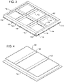
- FIG. 3 is a perspective view of a battery enclosure 100 with the top cover 120 removed.
- the outer covers 110 are shown coupled to the bottom panel 102 with the crossbeams 112 and the longitudinal beam 130 in place as described above with respect to FIGS. 1 and 2 .
- the outer covers 110, bottom panel 102, crossbeams 112, and longitudinal beam 130 are the same as shown and described above.
- the crossbeams 112 and longitudinal beam 130 define six recesses or cavities in which components of the battery may rest or be secured.
- each of the cavities may contain one or more battery cells, cooling units, and other hardware for the battery.
- the use of more than four crossbeams 112 or different arrangements of the longitudinal beam 130 and crossbeams 112 will result in different shaped or sized cavities to hold battery components and may be shaped as desired to pack as many battery components into the battery enclosure 100 as possible to maximize the energy storage capacity of the battery.
- FIG. 4 is a perspective view of the top cover 120 of the battery enclosure 100 of FIG. 1 , according to some embodiments.
- the top cover 120 is formed of the organosheet material and includes reinforcing strips 122 that provide additional structural support to the battery enclosure 100.
- the reinforcing strips 122 may include carbon fiber or glass fiber reinforcements, such as a unidirectional tape applied to the thermoplastic material and molded into the shape of the top cover 120.
- the reinforcing strips 122 are shown on an upper surface of the top cover 120, but may be positioned on an interior surface of the top cover 120, or both in some examples.
- the top cover 120 has a generally rectangular shape and is designed to pack battery components within the recess molded in the top cover 120.
- the top cover 120, and the battery enclosure 100 may have a non-rectangular shape, for example to fit in a particular location of a vehicle around other functional and structural elements of the vehicle.
- the top cover 120 includes a flange 124 that extends from side walls of the top cover beyond the recess formed in the top cover 120.
- the flange 124 is parallel to the surface of the recessed portion and mates with the bottom panel 102 to enclose the inner cavity of the battery enclosure 100.
- the flange 124 may be compressed or clamped against a seal, such as an O-ring, around the perimeter of the bottom panel 102 to seal the internal cavity from external elements or intrusion.
- FIG. 5 is a simplified diagram showing a process 500 for forming overmolded components of a battery enclosure 100.
- the process 500 may be performed by a single apparatus such as an assembly line or by a variety of machines in sequence.
- the process 500 may be used to form the bottom panel 102, crossbeams 112, longitudinal beam 130, top cover 120, and outer covers 110.
- the process 500 includes cutting a organosheet sheet 520, such as a sheet of prepreg material, to the size of a blank 522 for forming a component of the battery enclosure 100.
- the blank 522 for the top cover 120 may be a rectangular shape.
- the cutting may be performed by a die cutting machine, rotary cutter, or any other suitable cutting device.
- Multiple layers of the organosheet sheet 520 may be layered and cut at once, for example when multiple layers will be used to form a single component.
- the process 500 includes applying unidirectional tape strips 524 to the blank 522.
- the unidirectional tape strips 524 may include carbon fiber or glass fiber reinforcing material or may include other forms of reinforcement such as additional thermoplastic material or other such materials.
- the unidirectional tape strips 524 are applied such that after the component is formed by process 500, the unidirectional tape strips 524 reinforce particular areas of weakness or areas requiring additional strength or support.
- the blank 522 may not have any unidirectional tape strips 524 applied.
- the process 500 includes heating the blank 522.
- the blank 522 with the unidirectional tape strips applied thereto can be heated in a press 526 to press the components together as they are heated and become pliable.
- the heating of the thermoplastic material allows the thermoplastic of the blank 522 to fuse together into a single component with the unidirectional tape strips 524.
- the process 500 includes placing the blank 522 into a mold 528.
- the blank 522 typically has been heated previous to this step and is prepared for shaping.
- the mold 528 includes a passage 530 for injection of thermoplastic material to overmold additional features or geometry onto the blank 522 as it is formed in the mold.
- the mold 528 may receive one or more additional elements, such as threaded inserts, bushings, metal plates, honeycomb structure, and other pieces that will be overmolded to become integral with the blank 522.
- the process 500 includes applying force to the mold 528 to form the blank 522 into the desired shape. At the same time, pressure is applied to drive thermoplastic material 532 through the passage 530 into the mold for the overmolding process.
- the thermoplastic material 532 may, for example, be forced by an injection molding apparatus to enter through the passage 530.
- the process 500 includes cooling the mold 528 to solidify the thermoplastic material 532 and complete the overmolding process.
- the thermoplastic material 532 and the blank 522 set in the shape of the mold, setting the final shape of the component formed by the process 500.
- the completed component 536 with the overmolded features 534 is removed from the mold 528 in its completed form for further assembly.
- FIG. 6 is a simplified diagram showing a process 600 for assembling components of a battery enclosure 100.
- the process 600 includes joining the components into subassemblies that can be releasably joined together to form the battery enclosure 100.
- the components of the battery enclosure 100 are formed separately and then joined as shown in FIG. 6 .
- the various components may each be formed by a process such as the process 500 of FIG. 5 before being assembled as shown in FIG. 6 .
- the crossbeams 112 are joined to the top cover 120.
- the joining may be accomplished by thermoplastic welding or through structural fasteners such as screws.
- the thermoplastic welding may include hot plate welding, infrared welding, ultrasonic welding, vibration welding, friction welding, bonding, or other such welding processes that join thermoplastics together by melting and fusing.
- the components may be joined by bonding with adhesives such as glues or other such materials.
- the outer covers 110 may be integrally formed with the honeycomb structures 114 described and may be removable with respect to top cover 120.
- the outer covers 110 are coupled with the top cover 120 to form a top cover subassembly 160.
- the outer covers 110 may be joined or fused to the top cover 120 permanently to form the top cover subassembly 160 in a single component that attaches to the bottom panel 102.
- the bottom panel 102 receives the components of the battery including the cooling units 140 that are provided to cool the battery as well as the cells 150 that make up the energy storage of the battery.
- the bottom panel 102 may be a single flat sheet with structural ribs 104 that receive the cooling units 140 and the cells 150 or may include recesses to receive the cooling units 140 and cells 150.
- the cooling units 140 and cells 150 may be permanently installed or removably coupled to the bottom panel 102 to allow for maintenance or replacement of cells 150 if needed.
- the bottom panel 102, the cells 150, and the cooling units 140 form a bottom subassembly 170.
- the bottom subassembly 170 and the top cover subassembly 160 releasably couple together via the attachment member 116 to form the battery enclosure 100 and the completed battery.
- FIG. 7 is a flow chart depicting a process 700 for forming a battery enclosure 100.
- the process may be carried out by a single apparatus, by a number of machines in a particular sequence, or in varying orders. Though the steps presented are shown in sequential order, the steps may be performed in any order as needed.
- the process 700 includes forming a top panel.
- the top panel includes the top cover 120, the crossbeams 112, and may include the outer covers 110.
- the top panel may include the top cover subassembly 160 of FIG. 6 .
- Forming the top panel may include a number of subprocesses including molding the top cover 120, forming the crossbeam 112, forming the outer cover 110, and coupling the crossbeams 112 to the top cover 120.
- the process 700 includes molding the top cover 120.
- the top cover 120 may be molded using process 500 to form the recessed cavity and the flanges 124 of top cover 120.
- the top cover 120 may be formed of organosheet sheets as described above.
- the process 700 includes forming a crossbeam 112.
- the crossbeam 112 is formed by process 500 and includes overmolding structural ribs out of thermoplastic material onto the crossbeam 112 to increase the strength and rigidity of the crossbeams 112.
- the crossbeam 112 is formed of organosheet sheets and thermoplastic material as described above.
- the process 700 includes forming the outer cover 110.
- the outer cover 110 may be formed in several steps, such as molding the flanges in a first step, forming or attaching the attachment member 116 in a second step, and securing the honeycomb structure 114 in a third step. One or all of these steps may be performed at once by overmolding the outer cover with the attachment member 116 and the honeycomb structure 114 according to process 500.
- the process 700 includes coupling the crossbeam 112 to the top cover 120. This may be accomplished by welding, fusing, or securing with fasteners, the crossbeam 112 to the inner surface of the recess of the top cover 120.
- the process 700 includes forming the bottom panel 102.
- the bottom panel 102 may be formed in a number of subprocesses that may be accomplished sequentially or all at once, such as according to the process 500.
- the bottom panel 102 is formed by first molding a bottom sheet at 722. This may include cutting a blank from a sheet of organosheet and also may include forming one or more recesses to accept or receive components of the battery.
- the bottom panel 102 is further formed by securing or forming structural ribs 104 onto the bottom panel 102. This may be accomplished, for example, by overmolding the bottom panel 102 according to process 500.
- the process 700 includes coupling a longitudinal beam 130 to the bottom panel 102.
- the longitudinal beam 130 may be formed according to the same method as the crossbeams 112, according to process 500.
- the longitudinal beam 130 may be permanently affixed to the bottom panel, for example by welding, adhesive, or overmolding, or may be releasably coupled to the bottom panel 102.
- the process 700 includes securing the top panel to the bottom panel.
- This step includes coupling the top cover 120, with the crossbeams 112 attached thereto, to the bottom panel 102 and securing the two together by coupling the outer covers 110 to the bottom panel 102, sandwiching the top cover 120 in between.
- the outer covers 110 are secured to the bottom panel 102 by connecting the attachment members 116 of the outer covers 110 to the bottom panel to form the battery enclosure 100.
- the battery enclosure 100 has battery components such as cooling units and cells inserted into the internal cavity of the battery enclosure 100 before securing the bottom panel 102 and the top panel together.
- the cleaning machine may use air legs or configurations in non-vertical directions, in in which case the terms "top” and “bottom” may refer to positions not vertical but oriented diagonally as well.
- ranges of values herein are merely intended to serve as a shorthand method of referring individually to each separate value falling within the range, unless otherwise indicated herein and each separate value is incorporated into the specification as if it were individually recited herein. All methods described herein can be performed in any suitable order unless otherwise indicated herein or otherwise clearly contradicted by context.
Landscapes
- Chemical & Material Sciences (AREA)
- Chemical Kinetics & Catalysis (AREA)
- Electrochemistry (AREA)
- General Chemical & Material Sciences (AREA)
- Engineering & Computer Science (AREA)
- Inorganic Chemistry (AREA)
- Materials Engineering (AREA)
- Composite Materials (AREA)
- Mechanical Engineering (AREA)
- Transportation (AREA)
- Power Engineering (AREA)
- Sustainable Energy (AREA)
- Sustainable Development (AREA)
- Life Sciences & Earth Sciences (AREA)
- Aviation & Aerospace Engineering (AREA)
- Battery Mounting, Suspending (AREA)
- Arrangement Or Mounting Of Propulsion Units For Vehicles (AREA)
- Toys (AREA)
- Packages (AREA)
- Supplying Of Containers To The Packaging Station (AREA)
Claims (18)
- Batteriegehäuse (100) für eine Batterie eines Fahrzeugsystems, wobei der Batteriegehäuse Folgendes umfasst:(I) ein erstes Bodenpanel (102), das Folgendes umfasst:(i) eine erste verstärkte Thermoplast-Verbundplatte;(ii) eine oder mehrere Strukturrippen (104), die aus thermoplastischem Material gebildet sind, um Gewicht zu verteilen; und(iii) ein erstes Anbringungselement, das an einem Umfang des Bodenpanels positioniert ist;(II) ein Oberseitenpanel, um Zellen (150) der Batterie einzuschließen, wenn es an das Bodenpanel (102) gekoppelt ist, wobei das Oberseitenpanel Folgendes umfasst:(iv) eine Oberseiten-Innenabdeckung (120), die eine zweite verstärkte thermoplastische Verbundplatte umfasst, die geformt ist, um einen Hohlraum zu definieren;(v) einen oder mehrere Querträger (112) die an eine Innenoberfläche der Oberseiten-Innenabdeckung (120) gekoppelt sind;(III) eine oder mehrere Außenabdeckungen (110), die Folgendes umfassen:(vi) einen Außenflansch (124), der ein zweites Anbringungselement aufweist, das darin beinhaltet ist, um freigebbar an das erste Anbringungselement gekoppelt zu sein;(vii) eine Strukturwabe (114); und(viii) einen Innenflansch, um das Oberseitenpanel in Position zu halten, wenn die eine oder mehreren Außenabdeckungen an dem Bodenpanel befestigt sind.
- Batteriegehäuse nach Anspruch 1, wobei der eine oder die mehreren Querträger (112) eine dritte verstärkte thermoplastische Verbundplatte umfassen, und integral gebildete thermoplastische Stützrippen umfassen, wobei bevorzugt die erste verstärkte thermoplastische Verbundplatte, die zweite verstärkte thermoplastische Verbundplatte und die dritte verstärkte thermoplastische Verbundplatte ein identisches thermoplastisches Material umfassen.
- Batteriegehäuse nach Anspruch 1 oder 2, der weiter einen Längsträger (130) umfasst, der an das Bodenpanel (102) gekoppelt ist, und wobei der Längsträger und der eine oder die mehreren Querträger (112) eine Vielzahl von Positionen definieren, um die Zellen der Batterie aufzunehmen.
- Batteriegehäuse nach Anspruch 4, wobei der Längsträger (130) aus einem verstärkten thermoplastischen Verbundmaterial gebildet ist, wobei der Längsträger bevorzugt integral gebildete Anbringungsstellen für Bauteile der Batterie umfasst.
- Batteriegehäuse nach einem der Ansprüche 1 bis 4, wobei die erste verstärkte thermoplastische Verbundplatte mit mindestens einem aus Glasfasern oder Carbonfasern verstärkt ist.
- Batteriegehäuse nach einem oder mehreren der Ansprüche 1 bis 5, wobei der eine oder die mehreren Querträger (112) und das erste Anbringungselement integral auf die erste verstärkte thermoplastische Verbundplatte gebildet sind.
- Batteriegehäuse nach einem oder mehreren der Ansprüche 1 bis 6, wobei die Oberseiten-Innenabdeckung (120) und das Bodenpanel (102) jeweils weiter eine elektromagnetische Interferenz-Abschirmschicht und eine Brandschutzschicht umfassen.
- Batteriegehäuse nach einem oder mehreren der Ansprüche 1 bis 8, wobei der eine oder die mehreren Querträger (112) durch mindestens eines der Folgenden an die Oberseiten-Innenabdeckung gekoppelt sind:Heißelementschweißen;Infrarotschweißen;Ultraschallschweißen;Vibrationsschweißen;Reibschweißen;Kleben; oderStrukturbefestigungselemente.
- Batteriegehäuse nach einem oder mehreren der Ansprüche 1 bis 8, wobei die eine oder die mehreren Außenabdeckungen (110) an die Oberseiten-Innenabdeckung an einem Umfang der Oberseiten-Innenabdeckung gekoppelt sind, wobei die eine oder die mehreren Außenabdeckungen bevorzugt eine Wabenstruktur (114) beinhalten, die aus einem Thermoplast gebildet und um den Umfang der Oberseiten-Innenabdeckung positioniert ist, um ein Innenfach des Batteriegehäusees vor Stößen zu schützen.
- Batteriegehäuse nach einem oder mehreren der Ansprüche 1 bis 9, wobei das Bodenpanel (102) eine integrierte Dichtung um den Umfang des Bodenpanels umfasst, die einen Innenraum des Batteriegehäusees abdichtet, wenn das Bodenpanel (102), das Oberseitenpanel (120) und eine oder mehrere Außenabdeckungen (110) aneinander gekoppelt sind.
- Batteriegehäuse nach einem oder mehreren der Ansprüche 1 bis 10, wobei die eine oder die mehreren Außenabdeckungen (110) in die Oberseiten-Innenabdeckung (120) integriert sind.
- Verfahren zum Herstellen eines Batteriegehäusees für ein Fahrzeugsystem, wobei das Verfahren Folgendes umfasst:(I) Bilden eines Oberseitenpanels durch mindestens:(i) Formen einer Oberseitenabdeckung (120) aus einer ersten thermoplastischen Verbundplatte;(II) Bilden eines Querträgers (112) durch Spritzgießen von Stützrippen (104) auf die zweite thermoplastische Verbundplatte, während der Querträger geformt wird;(III) Bilden einer Außenabdeckung (110), die eine integrierte Wabenstruktur (114) und erste Anbringungselemente umfasst; und(IV) Koppeln des Querträgers (112) und der Außenabdeckung (110) an die Oberseitenabdeckung (120);(V) Bilden eines Bodenpanels (102) durch mindestens:(ii) Formen eines Bodenpanels aus einer dritten thermoplastischen Verbundplatte; und(iii) integrales Bilden von Stützrippen (104) und zweiten Anbringungselementen auf dem Bodenpanel;(iv) Koppeln eines Längsträgers (130) an das Bodenpanel (102); und(VI) Befestigen des Oberseitenpanels (120) an dem Bodenpanel (102) durch Koppeln der ersten Anbringungselemente und der zweiten Anbringungselemente.
- Verfahren nach Anspruch 12, wobei das Formen des Bodenpanels Folgendes umfasst:(i) Positionieren eines unidirektionalen Bandes auf mindestens einer Seite der thermoplastischen Verbundplatte; und(ii) Anlegen von Hitze und Druck an das unidirektionale Band und die zweite thermoplastische Verbundplatte, um das unidirektionale Band an die mindestens eine Seite der zweiten thermoplastischen Verbundplatte zu formen.
- Verfahren nach einem der Ansprüche 12 oder 13, wobei das Koppeln des Querträgers (112) und der Außenabdeckung (110) an die Oberseitenabdeckung (120) mindestens eines umfasst von:Heißelementschweißen;Infrarotschweißen;Ultraschallschweißen;Vibrationsschweißen;Reibschweißen;Kleben; oderBefestigungselementen.
- Verfahren nach einem oder mehreren der Ansprüche 12 bis 14, wobei das Bilden des Querträgers (112) Folgendes umfasst:(i) Zuschneiden der zweiten thermoplastischen Verbundplatte auf eine Vorformschicht;(ii) Aufbringen eines unidirektionalen Bandes an die zweite thermoplastische Verbundplatte;(iii) Anlegen von Hitze und Druck an die zweite thermoplastische Verbundplatte und das unidirektionale Band, um einen Rohling zu bilden;(iv) Laden des Rohlings in eine offene Form; und(v) Spritzgießen der Stützrippen auf den Rohling.
- Verfahren nach einem oder mehreren der Ansprüche 12 bis 15, wobei das Koppeln des Längsträgers (130) an das Bodenpanel (102) das integrale Bilden des Längsträgers mit dem Bodenpanel oder Befestigen des Längsträgers an dem Bodenpanel umfasst.
- Verfahren nach einem oder mehreren der Ansprüche 12 bis 16, wobei der Querträger (112) und die Außenabdeckung (110) aus glasfaser- oder carbonfaserverstärktem Thermoplast gebildet werden.
- Verfahren nach einem oder mehreren der Ansprüche 12 bis 17, wobei:(i) das Formen der Oberseitenabdeckung (120) das Koppeln der ersten thermoplastischen Verbundplatte an eine erste elektromagnetischen Abschirmschicht und eine Brandschutzschicht umfasst; und(ii) das Formen des Bodenpanels (102) das Koppeln der dritten thermoplastischen Verbundplatte an eine zweite elektromagnetische Abschirmschicht und eine zweite Brandschutzschicht umfasst.
Applications Claiming Priority (1)
| Application Number | Priority Date | Filing Date | Title |
|---|---|---|---|
| US16/827,903 US11688909B2 (en) | 2020-03-24 | 2020-03-24 | Battery enclosure |
Publications (2)
| Publication Number | Publication Date |
|---|---|
| EP3886240A1 EP3886240A1 (de) | 2021-09-29 |
| EP3886240B1 true EP3886240B1 (de) | 2022-12-14 |
Family
ID=75143422
Family Applications (1)
| Application Number | Title | Priority Date | Filing Date |
|---|---|---|---|
| EP21162031.5A Active EP3886240B1 (de) | 2020-03-24 | 2021-03-11 | Batteriegehäuse |
Country Status (4)
| Country | Link |
|---|---|
| US (2) | US11688909B2 (de) |
| EP (1) | EP3886240B1 (de) |
| CA (1) | CA3109697A1 (de) |
| ES (1) | ES2936339T3 (de) |
Families Citing this family (19)
| Publication number | Priority date | Publication date | Assignee | Title |
|---|---|---|---|---|
| WO2021185632A1 (en) * | 2020-03-19 | 2021-09-23 | Mubea Carbo Tech Gmbh | Protecting member for a battery structure of an electric vehicle |
| US11688909B2 (en) | 2020-03-24 | 2023-06-27 | Johns Manville | Battery enclosure |
| EP4002566A1 (de) * | 2020-11-12 | 2022-05-25 | Crompton Technology Group Limited | Elektrisches gehäuse |
| DE102021210758A1 (de) * | 2021-09-27 | 2023-03-30 | Kautex Textron Gmbh & Co. Kg | Batterieschale aus Kunststoff aufweisend eine Formmasse und einen endlosfaserverstärkten Einleger, Werkzeug sowie Verfahren zum Herstellen einer Batterieschale, Traktionsbatterie und Kraftfahrzeug |
| DE102021125265A1 (de) | 2021-09-29 | 2023-03-30 | Bayerische Motoren Werke Aktiengesellschaft | Verfahren zur Herstellung eines Gehäuseteils eines Speichergehäuses eines elektrischen Energiespeichers, Gehäuseteil sowie Speichergehäuse |
| US20230198043A1 (en) * | 2021-12-17 | 2023-06-22 | Stewart & Stevenson Llc | Battery module for locomotive |
| DE102022101036B3 (de) * | 2022-01-18 | 2023-02-23 | Azl Aachen Gmbh | Abdeckeinheit zum Verschließen eines Batteriegehäuses eines elektrisch angetriebenen Fahrzeugs und Verfahren zur Herstellung einer Abdeckeinheit |
| DE102022104812A1 (de) * | 2022-03-01 | 2023-09-07 | Azl Aachen Gmbh | Batteriegehäuse für ein elektrisch betriebenes Fahrzeug zur Anordnung von Batteriezellen, Querträger, Batterie und Verfahren |
| CN114976470B (zh) * | 2022-07-28 | 2022-10-21 | 广东采日能源科技有限公司 | 一种储能电池箱 |
| WO2024021071A1 (zh) * | 2022-07-29 | 2024-02-01 | 宁德时代新能源科技股份有限公司 | 电池的箱体、电池以及用电装置 |
| US12562442B2 (en) * | 2022-09-09 | 2026-02-24 | Eve Power Co., Ltd. | Lid plate and battery |
| CN115312952B (zh) * | 2022-09-16 | 2023-09-22 | 江苏奥特帕斯新能源科技有限公司 | 电动汽车复合框架式电池箱体、组装工装及其组装方法 |
| US12322823B2 (en) * | 2022-09-30 | 2025-06-03 | Ford Global Technologies, Llc | Structurally reinforced enclosure covers for traction battery packs |
| US20240363921A1 (en) * | 2023-04-27 | 2024-10-31 | Sogefi Air & Cooling Usa, Inc. | Manufacture of a thermoplastic heat exchanger |
| JP2025519162A (ja) * | 2023-04-28 | 2025-06-24 | エルジー エナジー ソリューション リミテッド | バッテリーパック及びそれを含む自動車 |
| CN121241466A (zh) * | 2023-05-22 | 2025-12-30 | Sabic环球技术有限责任公司 | 具有突出的双壁电池分隔件和热失控屏障的电池包盖 |
| US20250158194A1 (en) * | 2023-11-10 | 2025-05-15 | Eve Energy Co., Ltd. | Battery pack box and battery pack |
| FR3163025A1 (fr) * | 2024-06-07 | 2025-12-12 | Stellantis Auto Sas | Vehicule automobile comprenant un bac de batterie qui comprend des traverses laterales soudees a des traverses inter-modules, et procede de fabrication d’un tel vehicule |
| CN119581775A (zh) * | 2025-02-08 | 2025-03-07 | 宁德时代新能源科技股份有限公司 | 电池包的上盖及其制造方法、电池包和用电设备 |
Citations (7)
| Publication number | Priority date | Publication date | Assignee | Title |
|---|---|---|---|---|
| JP2012126058A (ja) | 2010-12-16 | 2012-07-05 | Mitsubishi Motors Corp | バッテリトレイ |
| US8835033B2 (en) | 2012-03-23 | 2014-09-16 | Hyundai Motor Company | Battery pack case assembly for electric and hybrid vehicles using a plastic composite and method for manufacturing the same |
| US20190237720A1 (en) | 2018-01-31 | 2019-08-01 | Tpi Composites, Inc. | Composite battery enclosure |
| US20200001728A1 (en) | 2017-02-17 | 2020-01-02 | Mubea Carbo Tech Gmbh | Battery structure and protector |
| WO2020000090A1 (en) | 2018-06-25 | 2020-01-02 | Magna International Inc. | Battery frame |
| CN209912910U (zh) | 2019-04-16 | 2020-01-07 | 蔚来汽车有限公司 | 动力电池壳体、动力电池和车辆 |
| WO2021034420A1 (en) | 2019-08-19 | 2021-02-25 | Bridgestone Americas, Inc. | Structural composites for battery enclosure |
Family Cites Families (14)
| Publication number | Priority date | Publication date | Assignee | Title |
|---|---|---|---|---|
| US6705270B1 (en) * | 2000-04-26 | 2004-03-16 | Basf Corporation | Oil pan module for internal combustion engines |
| CN1820936A (zh) * | 2005-02-18 | 2006-08-23 | 冷鹭浩 | 一种表面为曲面的塑料蜂窝复合板 |
| US9331321B2 (en) * | 2011-03-31 | 2016-05-03 | GM Global Technology Operations LLC | Fabric composite support or enclosure for an automotive battery pack |
| DE102011111744B4 (de) * | 2011-08-24 | 2013-09-05 | Daimler Ag | Steuergehäusemodul und Herstellungsverfahren |
| US9590216B2 (en) | 2014-04-30 | 2017-03-07 | Ford Global Technologies, Llc | Electric vehicle battery assembly enclosure |
| US11208156B2 (en) * | 2014-06-13 | 2021-12-28 | Altec Industries, Inc. | Sidepack floor and methods of making and using same |
| US20160104873A1 (en) * | 2014-10-10 | 2016-04-14 | Vecture Inc. | Battery pack system and method for fabrication thereof |
| JP6520808B2 (ja) * | 2016-04-21 | 2019-05-29 | トヨタ自動車株式会社 | 車両のバッテリ搭載構造 |
| US10230083B2 (en) * | 2016-11-01 | 2019-03-12 | Ford Global Technologies, Llc | Traction battery retention assembly |
| WO2018213306A1 (en) * | 2017-05-16 | 2018-11-22 | Shape Corp. | Vehicle battery tray having tub-based component |
| DE102017217814B4 (de) * | 2017-10-06 | 2021-02-18 | Thyssenkrupp Ag | Batteriegehäuse für ein Fahrzeug |
| DE102018120268A1 (de) * | 2018-08-21 | 2020-02-27 | Bmw Ag | Batteriekasten mit Verstärkungselement |
| US11431066B2 (en) * | 2018-11-13 | 2022-08-30 | Rivian Ip Holdings, Llc | Battery pack water drain system |
| US11688909B2 (en) | 2020-03-24 | 2023-06-27 | Johns Manville | Battery enclosure |
-
2020
- 2020-03-24 US US16/827,903 patent/US11688909B2/en active Active
-
2021
- 2021-02-23 CA CA3109697A patent/CA3109697A1/en active Pending
- 2021-03-11 ES ES21162031T patent/ES2936339T3/es active Active
- 2021-03-11 EP EP21162031.5A patent/EP3886240B1/de active Active
-
2023
- 2023-03-29 US US18/127,869 patent/US12315943B2/en active Active
Patent Citations (7)
| Publication number | Priority date | Publication date | Assignee | Title |
|---|---|---|---|---|
| JP2012126058A (ja) | 2010-12-16 | 2012-07-05 | Mitsubishi Motors Corp | バッテリトレイ |
| US8835033B2 (en) | 2012-03-23 | 2014-09-16 | Hyundai Motor Company | Battery pack case assembly for electric and hybrid vehicles using a plastic composite and method for manufacturing the same |
| US20200001728A1 (en) | 2017-02-17 | 2020-01-02 | Mubea Carbo Tech Gmbh | Battery structure and protector |
| US20190237720A1 (en) | 2018-01-31 | 2019-08-01 | Tpi Composites, Inc. | Composite battery enclosure |
| WO2020000090A1 (en) | 2018-06-25 | 2020-01-02 | Magna International Inc. | Battery frame |
| CN209912910U (zh) | 2019-04-16 | 2020-01-07 | 蔚来汽车有限公司 | 动力电池壳体、动力电池和车辆 |
| WO2021034420A1 (en) | 2019-08-19 | 2021-02-25 | Bridgestone Americas, Inc. | Structural composites for battery enclosure |
Non-Patent Citations (1)
| Title |
|---|
| PEREIRA CARLOS: "Thermoplastic solutions for battery packs", CHEMISTRY THAT MATTERS CONFERENCE, 21 November 2019 (2019-11-21), pages 1 - 17, XP093113481, [retrieved on 20231219] |
Also Published As
| Publication number | Publication date |
|---|---|
| EP3886240A1 (de) | 2021-09-29 |
| US11688909B2 (en) | 2023-06-27 |
| ES2936339T3 (es) | 2023-03-16 |
| US12315943B2 (en) | 2025-05-27 |
| US20230231248A1 (en) | 2023-07-20 |
| CA3109697A1 (en) | 2021-09-24 |
| US20210305544A1 (en) | 2021-09-30 |
Similar Documents
| Publication | Publication Date | Title |
|---|---|---|
| EP3886240B1 (de) | Batteriegehäuse | |
| US12384469B2 (en) | Method of making a laminate, an energy absorbing device, an energy absorbing device composition, and a forming tool | |
| US12577727B2 (en) | Carrier with localized fibrous insert and methods | |
| US12573698B2 (en) | Hybrid energy-absorption for vehicle battery pack frames | |
| US20250326190A1 (en) | Structural Reinforcements | |
| CN107567478B (zh) | 具有热塑性环氧聚合物相的复合材料,由其制成的诸如载体的制品,及相关方法 | |
| CN110091821A (zh) | 具有波纹式接头的多部件复合能量吸收结构 | |
| WO2018115827A1 (en) | A monocoque structure | |
| US20160176460A1 (en) | Method for manufacturing vehicle components/structural components from a plastics material | |
| JP7376293B2 (ja) | 繊維強化樹脂複合材及び繊維強化樹脂複合材の製造方法 | |
| KR102398676B1 (ko) | 3차원 구조체와 이의 제조 방법 | |
| CN118435436A (zh) | 用于电池外壳的具有改进的接合部件的复合结构 | |
| JP7376295B2 (ja) | 繊維強化樹脂複合材及び繊維強化樹脂複合材の製造方法 | |
| Jayasankar | Advances In RTM Manufacturing Of Metal-FRP Hybrids By Self-Sealing And In-Mold Cleaning Techniques | |
| WO2025247724A1 (en) | A battery tray comprising fiber reinforced thermoplastic materials | |
| EP4313562A1 (de) | Systeme und verfahren zur herstellung von rotorblättern |
Legal Events
| Date | Code | Title | Description |
|---|---|---|---|
| PUAI | Public reference made under article 153(3) epc to a published international application that has entered the european phase |
Free format text: ORIGINAL CODE: 0009012 |
|
| STAA | Information on the status of an ep patent application or granted ep patent |
Free format text: STATUS: THE APPLICATION HAS BEEN PUBLISHED |
|
| AK | Designated contracting states |
Kind code of ref document: A1 Designated state(s): AL AT BE BG CH CY CZ DE DK EE ES FI FR GB GR HR HU IE IS IT LI LT LU LV MC MK MT NL NO PL PT RO RS SE SI SK SM TR |
|
| STAA | Information on the status of an ep patent application or granted ep patent |
Free format text: STATUS: REQUEST FOR EXAMINATION WAS MADE |
|
| 17P | Request for examination filed |
Effective date: 20220325 |
|
| RBV | Designated contracting states (corrected) |
Designated state(s): AL AT BE BG CH CY CZ DE DK EE ES FI FR GB GR HR HU IE IS IT LI LT LU LV MC MK MT NL NO PL PT RO RS SE SI SK SM TR |
|
| GRAP | Despatch of communication of intention to grant a patent |
Free format text: ORIGINAL CODE: EPIDOSNIGR1 |
|
| STAA | Information on the status of an ep patent application or granted ep patent |
Free format text: STATUS: GRANT OF PATENT IS INTENDED |
|
| INTG | Intention to grant announced |
Effective date: 20220628 |
|
| GRAS | Grant fee paid |
Free format text: ORIGINAL CODE: EPIDOSNIGR3 |
|
| GRAA | (expected) grant |
Free format text: ORIGINAL CODE: 0009210 |
|
| STAA | Information on the status of an ep patent application or granted ep patent |
Free format text: STATUS: THE PATENT HAS BEEN GRANTED |
|
| AK | Designated contracting states |
Kind code of ref document: B1 Designated state(s): AL AT BE BG CH CY CZ DE DK EE ES FI FR GB GR HR HU IE IS IT LI LT LU LV MC MK MT NL NO PL PT RO RS SE SI SK SM TR |
|
| REG | Reference to a national code |
Ref country code: GB Ref legal event code: FG4D |
|
| REG | Reference to a national code |
Ref country code: CH Ref legal event code: EP |
|
| REG | Reference to a national code |
Ref country code: DE Ref legal event code: R096 Ref document number: 602021000955 Country of ref document: DE |
|
| REG | Reference to a national code |
Ref country code: IE Ref legal event code: FG4D |
|
| REG | Reference to a national code |
Ref country code: AT Ref legal event code: REF Ref document number: 1538213 Country of ref document: AT Kind code of ref document: T Effective date: 20230115 |
|
| REG | Reference to a national code |
Ref country code: NL Ref legal event code: FP |
|
| REG | Reference to a national code |
Ref country code: SK Ref legal event code: T3 Ref document number: E 41112 Country of ref document: SK |
|
| REG | Reference to a national code |
Ref country code: ES Ref legal event code: FG2A Ref document number: 2936339 Country of ref document: ES Kind code of ref document: T3 Effective date: 20230316 |
|
| REG | Reference to a national code |
Ref country code: LT Ref legal event code: MG9D |
|
| PG25 | Lapsed in a contracting state [announced via postgrant information from national office to epo] |
Ref country code: SE Free format text: LAPSE BECAUSE OF FAILURE TO SUBMIT A TRANSLATION OF THE DESCRIPTION OR TO PAY THE FEE WITHIN THE PRESCRIBED TIME-LIMIT Effective date: 20221214 Ref country code: NO Free format text: LAPSE BECAUSE OF FAILURE TO SUBMIT A TRANSLATION OF THE DESCRIPTION OR TO PAY THE FEE WITHIN THE PRESCRIBED TIME-LIMIT Effective date: 20230314 Ref country code: LT Free format text: LAPSE BECAUSE OF FAILURE TO SUBMIT A TRANSLATION OF THE DESCRIPTION OR TO PAY THE FEE WITHIN THE PRESCRIBED TIME-LIMIT Effective date: 20221214 Ref country code: FI Free format text: LAPSE BECAUSE OF FAILURE TO SUBMIT A TRANSLATION OF THE DESCRIPTION OR TO PAY THE FEE WITHIN THE PRESCRIBED TIME-LIMIT Effective date: 20221214 |
|
| REG | Reference to a national code |
Ref country code: AT Ref legal event code: MK05 Ref document number: 1538213 Country of ref document: AT Kind code of ref document: T Effective date: 20221214 |
|
| PG25 | Lapsed in a contracting state [announced via postgrant information from national office to epo] |
Ref country code: RS Free format text: LAPSE BECAUSE OF FAILURE TO SUBMIT A TRANSLATION OF THE DESCRIPTION OR TO PAY THE FEE WITHIN THE PRESCRIBED TIME-LIMIT Effective date: 20221214 Ref country code: LV Free format text: LAPSE BECAUSE OF FAILURE TO SUBMIT A TRANSLATION OF THE DESCRIPTION OR TO PAY THE FEE WITHIN THE PRESCRIBED TIME-LIMIT Effective date: 20221214 Ref country code: HR Free format text: LAPSE BECAUSE OF FAILURE TO SUBMIT A TRANSLATION OF THE DESCRIPTION OR TO PAY THE FEE WITHIN THE PRESCRIBED TIME-LIMIT Effective date: 20221214 Ref country code: GR Free format text: LAPSE BECAUSE OF FAILURE TO SUBMIT A TRANSLATION OF THE DESCRIPTION OR TO PAY THE FEE WITHIN THE PRESCRIBED TIME-LIMIT Effective date: 20230315 |
|
| PG25 | Lapsed in a contracting state [announced via postgrant information from national office to epo] |
Ref country code: SM Free format text: LAPSE BECAUSE OF FAILURE TO SUBMIT A TRANSLATION OF THE DESCRIPTION OR TO PAY THE FEE WITHIN THE PRESCRIBED TIME-LIMIT Effective date: 20221214 Ref country code: RO Free format text: LAPSE BECAUSE OF FAILURE TO SUBMIT A TRANSLATION OF THE DESCRIPTION OR TO PAY THE FEE WITHIN THE PRESCRIBED TIME-LIMIT Effective date: 20221214 Ref country code: PT Free format text: LAPSE BECAUSE OF FAILURE TO SUBMIT A TRANSLATION OF THE DESCRIPTION OR TO PAY THE FEE WITHIN THE PRESCRIBED TIME-LIMIT Effective date: 20230414 Ref country code: EE Free format text: LAPSE BECAUSE OF FAILURE TO SUBMIT A TRANSLATION OF THE DESCRIPTION OR TO PAY THE FEE WITHIN THE PRESCRIBED TIME-LIMIT Effective date: 20221214 Ref country code: CZ Free format text: LAPSE BECAUSE OF FAILURE TO SUBMIT A TRANSLATION OF THE DESCRIPTION OR TO PAY THE FEE WITHIN THE PRESCRIBED TIME-LIMIT Effective date: 20221214 Ref country code: AT Free format text: LAPSE BECAUSE OF FAILURE TO SUBMIT A TRANSLATION OF THE DESCRIPTION OR TO PAY THE FEE WITHIN THE PRESCRIBED TIME-LIMIT Effective date: 20221214 |
|
| PG25 | Lapsed in a contracting state [announced via postgrant information from national office to epo] |
Ref country code: PL Free format text: LAPSE BECAUSE OF FAILURE TO SUBMIT A TRANSLATION OF THE DESCRIPTION OR TO PAY THE FEE WITHIN THE PRESCRIBED TIME-LIMIT Effective date: 20221214 Ref country code: IS Free format text: LAPSE BECAUSE OF FAILURE TO SUBMIT A TRANSLATION OF THE DESCRIPTION OR TO PAY THE FEE WITHIN THE PRESCRIBED TIME-LIMIT Effective date: 20230414 Ref country code: AL Free format text: LAPSE BECAUSE OF FAILURE TO SUBMIT A TRANSLATION OF THE DESCRIPTION OR TO PAY THE FEE WITHIN THE PRESCRIBED TIME-LIMIT Effective date: 20221214 |
|
| REG | Reference to a national code |
Ref country code: DE Ref legal event code: R026 Ref document number: 602021000955 Country of ref document: DE |
|
| PLBI | Opposition filed |
Free format text: ORIGINAL CODE: 0009260 |
|
| PLAX | Notice of opposition and request to file observation + time limit sent |
Free format text: ORIGINAL CODE: EPIDOSNOBS2 |
|
| 26 | Opposition filed |
Opponent name: SABIC GLOBAL TECHNOLOGIES B.V. / SABIC PETROCHEMICALS B.V. Effective date: 20230914 |
|
| PG25 | Lapsed in a contracting state [announced via postgrant information from national office to epo] |
Ref country code: MC Free format text: LAPSE BECAUSE OF FAILURE TO SUBMIT A TRANSLATION OF THE DESCRIPTION OR TO PAY THE FEE WITHIN THE PRESCRIBED TIME-LIMIT Effective date: 20221214 Ref country code: DK Free format text: LAPSE BECAUSE OF FAILURE TO SUBMIT A TRANSLATION OF THE DESCRIPTION OR TO PAY THE FEE WITHIN THE PRESCRIBED TIME-LIMIT Effective date: 20221214 |
|
| PG25 | Lapsed in a contracting state [announced via postgrant information from national office to epo] |
Ref country code: SI Free format text: LAPSE BECAUSE OF FAILURE TO SUBMIT A TRANSLATION OF THE DESCRIPTION OR TO PAY THE FEE WITHIN THE PRESCRIBED TIME-LIMIT Effective date: 20221214 |
|
| PG25 | Lapsed in a contracting state [announced via postgrant information from national office to epo] |
Ref country code: LU Free format text: LAPSE BECAUSE OF NON-PAYMENT OF DUE FEES Effective date: 20230311 |
|
| REG | Reference to a national code |
Ref country code: IE Ref legal event code: MM4A |
|
| PG25 | Lapsed in a contracting state [announced via postgrant information from national office to epo] |
Ref country code: IE Free format text: LAPSE BECAUSE OF NON-PAYMENT OF DUE FEES Effective date: 20230311 |
|
| PLBB | Reply of patent proprietor to notice(s) of opposition received |
Free format text: ORIGINAL CODE: EPIDOSNOBS3 |
|
| REG | Reference to a national code |
Ref country code: CH Ref legal event code: PL |
|
| PG25 | Lapsed in a contracting state [announced via postgrant information from national office to epo] |
Ref country code: BG Free format text: LAPSE BECAUSE OF FAILURE TO SUBMIT A TRANSLATION OF THE DESCRIPTION OR TO PAY THE FEE WITHIN THE PRESCRIBED TIME-LIMIT Effective date: 20221214 |
|
| PG25 | Lapsed in a contracting state [announced via postgrant information from national office to epo] |
Ref country code: BG Free format text: LAPSE BECAUSE OF FAILURE TO SUBMIT A TRANSLATION OF THE DESCRIPTION OR TO PAY THE FEE WITHIN THE PRESCRIBED TIME-LIMIT Effective date: 20221214 |
|
| PG25 | Lapsed in a contracting state [announced via postgrant information from national office to epo] |
Ref country code: CH Free format text: LAPSE BECAUSE OF NON-PAYMENT OF DUE FEES Effective date: 20240331 |
|
| PGFP | Annual fee paid to national office [announced via postgrant information from national office to epo] |
Ref country code: DE Payment date: 20250327 Year of fee payment: 5 |
|
| PGFP | Annual fee paid to national office [announced via postgrant information from national office to epo] |
Ref country code: NL Payment date: 20250327 Year of fee payment: 5 |
|
| PGFP | Annual fee paid to national office [announced via postgrant information from national office to epo] |
Ref country code: BE Payment date: 20250327 Year of fee payment: 5 |
|
| PGFP | Annual fee paid to national office [announced via postgrant information from national office to epo] |
Ref country code: FR Payment date: 20250325 Year of fee payment: 5 |
|
| PGFP | Annual fee paid to national office [announced via postgrant information from national office to epo] |
Ref country code: SK Payment date: 20250218 Year of fee payment: 5 Ref country code: GB Payment date: 20250327 Year of fee payment: 5 Ref country code: IT Payment date: 20250319 Year of fee payment: 5 |
|
| PGFP | Annual fee paid to national office [announced via postgrant information from national office to epo] |
Ref country code: ES Payment date: 20250401 Year of fee payment: 5 |
|
| PG25 | Lapsed in a contracting state [announced via postgrant information from national office to epo] |
Ref country code: CY Free format text: LAPSE BECAUSE OF FAILURE TO SUBMIT A TRANSLATION OF THE DESCRIPTION OR TO PAY THE FEE WITHIN THE PRESCRIBED TIME-LIMIT; INVALID AB INITIO Effective date: 20210311 |
|
| PG25 | Lapsed in a contracting state [announced via postgrant information from national office to epo] |
Ref country code: HU Free format text: LAPSE BECAUSE OF FAILURE TO SUBMIT A TRANSLATION OF THE DESCRIPTION OR TO PAY THE FEE WITHIN THE PRESCRIBED TIME-LIMIT; INVALID AB INITIO Effective date: 20210311 |
|
| REG | Reference to a national code |
Ref country code: DE Ref legal event code: R100 Ref document number: 602021000955 Country of ref document: DE |
|
| PG25 | Lapsed in a contracting state [announced via postgrant information from national office to epo] |
Ref country code: TR Free format text: LAPSE BECAUSE OF FAILURE TO SUBMIT A TRANSLATION OF THE DESCRIPTION OR TO PAY THE FEE WITHIN THE PRESCRIBED TIME-LIMIT Effective date: 20221214 |
|
| PLCK | Communication despatched that opposition was rejected |
Free format text: ORIGINAL CODE: EPIDOSNREJ1 |
|
| PLBN | Opposition rejected |
Free format text: ORIGINAL CODE: 0009273 |
|
| STAA | Information on the status of an ep patent application or granted ep patent |
Free format text: STATUS: OPPOSITION REJECTED |
|
| REG | Reference to a national code |
Ref country code: CH Ref legal event code: L18 Free format text: ST27 STATUS EVENT CODE: U-0-0-L10-L18 (AS PROVIDED BY THE NATIONAL OFFICE) Effective date: 20260114 |
|
| 27O | Opposition rejected |
Effective date: 20250916 |