EP3886199A1 - Battery pack - Google Patents
Battery pack Download PDFInfo
- Publication number
- EP3886199A1 EP3886199A1 EP19903378.8A EP19903378A EP3886199A1 EP 3886199 A1 EP3886199 A1 EP 3886199A1 EP 19903378 A EP19903378 A EP 19903378A EP 3886199 A1 EP3886199 A1 EP 3886199A1
- Authority
- EP
- European Patent Office
- Prior art keywords
- connecting portion
- box body
- battery pack
- battery module
- fixed
- Prior art date
- Legal status (The legal status is an assumption and is not a legal conclusion. Google has not performed a legal analysis and makes no representation as to the accuracy of the status listed.)
- Granted
Links
Images

Classifications
-
- H—ELECTRICITY
- H01—ELECTRIC ELEMENTS
- H01M—PROCESSES OR MEANS, e.g. BATTERIES, FOR THE DIRECT CONVERSION OF CHEMICAL ENERGY INTO ELECTRICAL ENERGY
- H01M50/00—Constructional details or processes of manufacture of the non-active parts of electrochemical cells other than fuel cells, e.g. hybrid cells
- H01M50/20—Mountings; Secondary casings or frames; Racks, modules or packs; Suspension devices; Shock absorbers; Transport or carrying devices; Holders
- H01M50/204—Racks, modules or packs for multiple batteries or multiple cells
- H01M50/207—Racks, modules or packs for multiple batteries or multiple cells characterised by their shape
- H01M50/209—Racks, modules or packs for multiple batteries or multiple cells characterised by their shape adapted for prismatic or rectangular cells
-
- H—ELECTRICITY
- H01—ELECTRIC ELEMENTS
- H01M—PROCESSES OR MEANS, e.g. BATTERIES, FOR THE DIRECT CONVERSION OF CHEMICAL ENERGY INTO ELECTRICAL ENERGY
- H01M50/00—Constructional details or processes of manufacture of the non-active parts of electrochemical cells other than fuel cells, e.g. hybrid cells
- H01M50/20—Mountings; Secondary casings or frames; Racks, modules or packs; Suspension devices; Shock absorbers; Transport or carrying devices; Holders
- H01M50/204—Racks, modules or packs for multiple batteries or multiple cells
-
- B—PERFORMING OPERATIONS; TRANSPORTING
- B60—VEHICLES IN GENERAL
- B60K—ARRANGEMENT OR MOUNTING OF PROPULSION UNITS OR OF TRANSMISSIONS IN VEHICLES; ARRANGEMENT OR MOUNTING OF PLURAL DIVERSE PRIME-MOVERS IN VEHICLES; AUXILIARY DRIVES FOR VEHICLES; INSTRUMENTATION OR DASHBOARDS FOR VEHICLES; ARRANGEMENTS IN CONNECTION WITH COOLING, AIR INTAKE, GAS EXHAUST OR FUEL SUPPLY OF PROPULSION UNITS IN VEHICLES
- B60K1/00—Arrangement or mounting of electrical propulsion units
- B60K1/04—Arrangement or mounting of electrical propulsion units of the electric storage means for propulsion
-
- B—PERFORMING OPERATIONS; TRANSPORTING
- B60—VEHICLES IN GENERAL
- B60L—PROPULSION OF ELECTRICALLY-PROPELLED VEHICLES; SUPPLYING ELECTRIC POWER FOR AUXILIARY EQUIPMENT OF ELECTRICALLY-PROPELLED VEHICLES; ELECTRODYNAMIC BRAKE SYSTEMS FOR VEHICLES IN GENERAL; MAGNETIC SUSPENSION OR LEVITATION FOR VEHICLES; MONITORING OPERATING VARIABLES OF ELECTRICALLY-PROPELLED VEHICLES; ELECTRIC SAFETY DEVICES FOR ELECTRICALLY-PROPELLED VEHICLES
- B60L50/00—Electric propulsion with power supplied within the vehicle
- B60L50/50—Electric propulsion with power supplied within the vehicle using propulsion power supplied by batteries or fuel cells
- B60L50/60—Electric propulsion with power supplied within the vehicle using propulsion power supplied by batteries or fuel cells using power supplied by batteries
- B60L50/64—Constructional details of batteries specially adapted for electric vehicles
-
- B—PERFORMING OPERATIONS; TRANSPORTING
- B60—VEHICLES IN GENERAL
- B60L—PROPULSION OF ELECTRICALLY-PROPELLED VEHICLES; SUPPLYING ELECTRIC POWER FOR AUXILIARY EQUIPMENT OF ELECTRICALLY-PROPELLED VEHICLES; ELECTRODYNAMIC BRAKE SYSTEMS FOR VEHICLES IN GENERAL; MAGNETIC SUSPENSION OR LEVITATION FOR VEHICLES; MONITORING OPERATING VARIABLES OF ELECTRICALLY-PROPELLED VEHICLES; ELECTRIC SAFETY DEVICES FOR ELECTRICALLY-PROPELLED VEHICLES
- B60L50/00—Electric propulsion with power supplied within the vehicle
- B60L50/50—Electric propulsion with power supplied within the vehicle using propulsion power supplied by batteries or fuel cells
- B60L50/60—Electric propulsion with power supplied within the vehicle using propulsion power supplied by batteries or fuel cells using power supplied by batteries
- B60L50/66—Arrangements of batteries
-
- H—ELECTRICITY
- H01—ELECTRIC ELEMENTS
- H01M—PROCESSES OR MEANS, e.g. BATTERIES, FOR THE DIRECT CONVERSION OF CHEMICAL ENERGY INTO ELECTRICAL ENERGY
- H01M50/00—Constructional details or processes of manufacture of the non-active parts of electrochemical cells other than fuel cells, e.g. hybrid cells
- H01M50/20—Mountings; Secondary casings or frames; Racks, modules or packs; Suspension devices; Shock absorbers; Transport or carrying devices; Holders
- H01M50/204—Racks, modules or packs for multiple batteries or multiple cells
- H01M50/207—Racks, modules or packs for multiple batteries or multiple cells characterised by their shape
- H01M50/211—Racks, modules or packs for multiple batteries or multiple cells characterised by their shape adapted for pouch cells
-
- H—ELECTRICITY
- H01—ELECTRIC ELEMENTS
- H01M—PROCESSES OR MEANS, e.g. BATTERIES, FOR THE DIRECT CONVERSION OF CHEMICAL ENERGY INTO ELECTRICAL ENERGY
- H01M50/00—Constructional details or processes of manufacture of the non-active parts of electrochemical cells other than fuel cells, e.g. hybrid cells
- H01M50/20—Mountings; Secondary casings or frames; Racks, modules or packs; Suspension devices; Shock absorbers; Transport or carrying devices; Holders
- H01M50/244—Secondary casings; Racks; Suspension devices; Carrying devices; Holders characterised by their mounting method
-
- H—ELECTRICITY
- H01—ELECTRIC ELEMENTS
- H01M—PROCESSES OR MEANS, e.g. BATTERIES, FOR THE DIRECT CONVERSION OF CHEMICAL ENERGY INTO ELECTRICAL ENERGY
- H01M50/00—Constructional details or processes of manufacture of the non-active parts of electrochemical cells other than fuel cells, e.g. hybrid cells
- H01M50/20—Mountings; Secondary casings or frames; Racks, modules or packs; Suspension devices; Shock absorbers; Transport or carrying devices; Holders
- H01M50/249—Mountings; Secondary casings or frames; Racks, modules or packs; Suspension devices; Shock absorbers; Transport or carrying devices; Holders specially adapted for aircraft or vehicles, e.g. cars or trains
-
- H—ELECTRICITY
- H01—ELECTRIC ELEMENTS
- H01M—PROCESSES OR MEANS, e.g. BATTERIES, FOR THE DIRECT CONVERSION OF CHEMICAL ENERGY INTO ELECTRICAL ENERGY
- H01M50/00—Constructional details or processes of manufacture of the non-active parts of electrochemical cells other than fuel cells, e.g. hybrid cells
- H01M50/20—Mountings; Secondary casings or frames; Racks, modules or packs; Suspension devices; Shock absorbers; Transport or carrying devices; Holders
- H01M50/271—Lids or covers for the racks or secondary casings
-
- H—ELECTRICITY
- H01—ELECTRIC ELEMENTS
- H01M—PROCESSES OR MEANS, e.g. BATTERIES, FOR THE DIRECT CONVERSION OF CHEMICAL ENERGY INTO ELECTRICAL ENERGY
- H01M50/00—Constructional details or processes of manufacture of the non-active parts of electrochemical cells other than fuel cells, e.g. hybrid cells
- H01M50/20—Mountings; Secondary casings or frames; Racks, modules or packs; Suspension devices; Shock absorbers; Transport or carrying devices; Holders
- H01M50/296—Mountings; Secondary casings or frames; Racks, modules or packs; Suspension devices; Shock absorbers; Transport or carrying devices; Holders characterised by terminals of battery packs
-
- H—ELECTRICITY
- H01—ELECTRIC ELEMENTS
- H01M—PROCESSES OR MEANS, e.g. BATTERIES, FOR THE DIRECT CONVERSION OF CHEMICAL ENERGY INTO ELECTRICAL ENERGY
- H01M50/00—Constructional details or processes of manufacture of the non-active parts of electrochemical cells other than fuel cells, e.g. hybrid cells
- H01M50/50—Current conducting connections for cells or batteries
- H01M50/502—Interconnectors for connecting terminals of adjacent batteries; Interconnectors for connecting cells outside a battery casing
- H01M50/507—Interconnectors for connecting terminals of adjacent batteries; Interconnectors for connecting cells outside a battery casing comprising an arrangement of two or more busbars within a container structure, e.g. busbar modules
-
- H—ELECTRICITY
- H01—ELECTRIC ELEMENTS
- H01M—PROCESSES OR MEANS, e.g. BATTERIES, FOR THE DIRECT CONVERSION OF CHEMICAL ENERGY INTO ELECTRICAL ENERGY
- H01M50/00—Constructional details or processes of manufacture of the non-active parts of electrochemical cells other than fuel cells, e.g. hybrid cells
- H01M50/50—Current conducting connections for cells or batteries
- H01M50/543—Terminals
-
- B—PERFORMING OPERATIONS; TRANSPORTING
- B60—VEHICLES IN GENERAL
- B60K—ARRANGEMENT OR MOUNTING OF PROPULSION UNITS OR OF TRANSMISSIONS IN VEHICLES; ARRANGEMENT OR MOUNTING OF PLURAL DIVERSE PRIME-MOVERS IN VEHICLES; AUXILIARY DRIVES FOR VEHICLES; INSTRUMENTATION OR DASHBOARDS FOR VEHICLES; ARRANGEMENTS IN CONNECTION WITH COOLING, AIR INTAKE, GAS EXHAUST OR FUEL SUPPLY OF PROPULSION UNITS IN VEHICLES
- B60K1/00—Arrangement or mounting of electrical propulsion units
- B60K1/04—Arrangement or mounting of electrical propulsion units of the electric storage means for propulsion
- B60K2001/0405—Arrangement or mounting of electrical propulsion units of the electric storage means for propulsion characterised by their position
- B60K2001/0438—Arrangement under the floor
-
- H—ELECTRICITY
- H01—ELECTRIC ELEMENTS
- H01M—PROCESSES OR MEANS, e.g. BATTERIES, FOR THE DIRECT CONVERSION OF CHEMICAL ENERGY INTO ELECTRICAL ENERGY
- H01M2220/00—Batteries for particular applications
- H01M2220/20—Batteries in motive systems, e.g. vehicle, ship, plane
-
- H—ELECTRICITY
- H01—ELECTRIC ELEMENTS
- H01M—PROCESSES OR MEANS, e.g. BATTERIES, FOR THE DIRECT CONVERSION OF CHEMICAL ENERGY INTO ELECTRICAL ENERGY
- H01M50/00—Constructional details or processes of manufacture of the non-active parts of electrochemical cells other than fuel cells, e.g. hybrid cells
- H01M50/10—Primary casings; Jackets or wrappings
- H01M50/147—Lids or covers
- H01M50/148—Lids or covers characterised by their shape
-
- H—ELECTRICITY
- H01—ELECTRIC ELEMENTS
- H01M—PROCESSES OR MEANS, e.g. BATTERIES, FOR THE DIRECT CONVERSION OF CHEMICAL ENERGY INTO ELECTRICAL ENERGY
- H01M50/00—Constructional details or processes of manufacture of the non-active parts of electrochemical cells other than fuel cells, e.g. hybrid cells
- H01M50/20—Mountings; Secondary casings or frames; Racks, modules or packs; Suspension devices; Shock absorbers; Transport or carrying devices; Holders
- H01M50/233—Mountings; Secondary casings or frames; Racks, modules or packs; Suspension devices; Shock absorbers; Transport or carrying devices; Holders characterised by physical properties of casings or racks, e.g. dimensions
- H01M50/242—Mountings; Secondary casings or frames; Racks, modules or packs; Suspension devices; Shock absorbers; Transport or carrying devices; Holders characterised by physical properties of casings or racks, e.g. dimensions adapted for protecting batteries against vibrations, collision impact or swelling
-
- Y—GENERAL TAGGING OF NEW TECHNOLOGICAL DEVELOPMENTS; GENERAL TAGGING OF CROSS-SECTIONAL TECHNOLOGIES SPANNING OVER SEVERAL SECTIONS OF THE IPC; TECHNICAL SUBJECTS COVERED BY FORMER USPC CROSS-REFERENCE ART COLLECTIONS [XRACs] AND DIGESTS
- Y02—TECHNOLOGIES OR APPLICATIONS FOR MITIGATION OR ADAPTATION AGAINST CLIMATE CHANGE
- Y02E—REDUCTION OF GREENHOUSE GAS [GHG] EMISSIONS, RELATED TO ENERGY GENERATION, TRANSMISSION OR DISTRIBUTION
- Y02E60/00—Enabling technologies; Technologies with a potential or indirect contribution to GHG emissions mitigation
- Y02E60/10—Energy storage using batteries
-
- Y—GENERAL TAGGING OF NEW TECHNOLOGICAL DEVELOPMENTS; GENERAL TAGGING OF CROSS-SECTIONAL TECHNOLOGIES SPANNING OVER SEVERAL SECTIONS OF THE IPC; TECHNICAL SUBJECTS COVERED BY FORMER USPC CROSS-REFERENCE ART COLLECTIONS [XRACs] AND DIGESTS
- Y02—TECHNOLOGIES OR APPLICATIONS FOR MITIGATION OR ADAPTATION AGAINST CLIMATE CHANGE
- Y02T—CLIMATE CHANGE MITIGATION TECHNOLOGIES RELATED TO TRANSPORTATION
- Y02T10/00—Road transport of goods or passengers
- Y02T10/60—Other road transportation technologies with climate change mitigation effect
- Y02T10/70—Energy storage systems for electromobility, e.g. batteries
Definitions
- the present invention relates to the field of batteries, and in particular, to a battery pack.
- fixing points of the battery pack at the bottom of the vehicle are usually merely provided at the peripheries of a box body of the battery pack, and arranged around the outside of box body of the battery pack. That is, the fixing points are provided at the peripheries of an upper box body and the peripheries of a lower box body, to fix the upper box body and the lower box body together and hoist them at the bottom of the vehicle.
- this fixing method is a challenge for the structural strength of the entire battery pack. Insufficient strength of the battery pack fixed at the bottom of the vehicle will cause safety problems.
- the box body of the battery pack is always needed to de made strong enough, and the weight of the box body can be well distributed to each fixing point.
- the purpose of the present invention is to provide a battery pack, which can improve the strength of the battery pack, thereby making the battery pack suitable to be fixed at a bottom of a vehicle.
- the present invention is provided with a battery pack, including a first battery module, a second battery module, and a box body.
- the first battery module and the second battery module are housed in the box body.
- the box body includes a lower box body configured to support the first battery module and the second battery module; and an upper box body fitting with the lower box body.
- the lower box body includes a first connecting portion, where the first connecting portion is located between the first battery module and the second battery module.
- the upper box body includes a second connecting portion, and the first connecting portion and the second connecting portion are fixed and connected.
- the first connecting portion is provided at a bottom of the lower box body.
- the first connecting portion of the lower box body has a first protrusion portion protruding upward along a height direction, and the first protrusion portion of the first connecting portion is fixed and connected to the second connecting portion of the upper box body.
- the second connecting portion of the upper box body has a second protrusion portion protruding downward along the height direction, and the second protrusion portion of the second connecting portion is fixed and connected to the first connecting portion.
- the second connecting portion of the upper box body has a second protrusion portion protruding downward along the height direction, and the first protrusion portion of the first connecting portion is fixed and connected to the second protrusion portion of the second connecting portion.
- the first protrusion portion of the first connecting portion is formed with a first recess recessed inward along the height direction, and the first recess and the second protrusion portion of the second connecting portion are fixed and connected by concave-convex fit.
- the second protrusion portion of the second connecting portion is formed with a second recess recessed inward along the height direction, and the second recess and the first protrusion portion of the first connecting portion are fixed and connected by concave-convex fit.
- a top surface of the upper box body is provided with a third recess recessed inward along the height direction, which is corresponding to a position of the second protrusion portion of the second connecting portion.
- the battery pack further includes a connecting beam, provided between the first connecting portion and the second connecting portion, and the connecting beam is fixed and connected to the first connecting portion and the second connecting portion.
- the lower box body includes a first peripheral portion
- the upper box body includes a second peripheral portion
- the first peripheral portion is fixed and connected to the second peripheral portion
- the beneficial effects of the present invention are as follows: in the battery pack of the present invention, the first connecting portion is provided between the first battery module and the second battery module, and the first connecting portion and the second connecting portion are fixed and connected, such that the strength of portions between the first battery module and the second battery module of the lower box body are improved. Therefore, the problem of the downward deflection of the lower box body is avoided and the strength of the battery pack is improved, such that the battery pack is suitable to be fixed at the bottom of the vehicle.
- First battery module 4 Connecting beam 2 Second battery module 5 Mounting beam 3 Box body R1 First recess 31 Lower box body R2 Second recess 311 First peripheral portion R3 Third recess 312 First connecting portion F1 First fastening member 312A First protrusion portion F2 Second fastening member 32 Upper box body B Battery 321 Second peripheral portion H Height direction 322 Second connecting portion L Lengthwise direction 322A Second protrusion portion W Widthwise direction
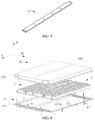
- FIG. 1 is an exploded perspective view of an embodiment of a battery pack of the present invention.
- FIG. 2 is a perspective view of a lower box body of the battery pack of FIG. 1 .
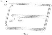
- FIG. 3 is a top perspective view of an upper box body of the battery pack of FIG. 1 .
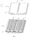
- FIG. 4 is a perspective view of the battery pack of FIG. 1 , where the upper box body is removed and a connecting beam not shown.
- FIG. 5 is a perspective view of the connecting beam of the battery pack of FIG. 1 .
- FIG. 6 is an exploded perspective view of another embodiment of the battery pack of the present invention.
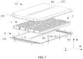
- FIG. 7 is an exploded perspective view of yet another embodiment of the battery pack of the present invention.
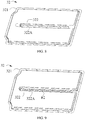
- FIG. 8 is a top perspective view of the upper box body of the battery pack of FIG. 7 from another angle.
- FIG. 9 is a top perspective view of another embodiment of the upper box body of the battery pack of the present invention.
- the battery pack of the present invention includes a first battery module 1, a second battery module 2, a box body 3 and a connecting beam 4, where the first battery module 1 and the second battery module 2 are housed in the box body 3.
- the box body 3 includes a lower box body 31 configured to support the first battery module 1 and the second battery module 2, and an upper box body 32 fitting with the lower box body 31.
- the lower box body 31 includes a first peripheral portion 311 and a first connecting portion 312.
- the first connecting portion 312 is located between the first battery module 1 and the second battery module 2.
- the upper box body 32 includes a second peripheral portion 321 and a second connecting portion 322.
- the first connecting portion 312 and the second connecting portion 322 are fixed and connected.
- the first peripheral portion 311 and the second peripheral portion 321 are connected and is configured to be hoisted at a bottom of a vehicle.
- first connecting portion 312 is not designed to be provided between the first battery module 1 and the second battery module 2 and there is no fixation and connection between the first connecting portion 312 and the second connecting portion 322. Portions between the first battery module 1 and the second battery module 2 of the lower box body 31 will flex downward due to the dead weight of the first battery module 1 and the second battery module 2, such that the battery pack is unfavorable to be fixed at the bottom of the vehicle.
- the first connecting portion 312 is provided between the first battery module 1 and the second battery module 2, and the first connecting portion 312 and the second connecting portion 322 are fixed and connected, such that the strength between the first battery module 1 and the second battery module 2 of the lower box body 31 is improved. Therefore, the downward deflection of the foregoing lower box body 31 is avoided and the strength of the battery pack is improved, such that the battery pack is suitable to be fixed at the bottom of the vehicle.
- first peripheral portion 311 and second peripheral portion 321 of the lower box body 31 and the upper box body 32 of the battery pack fix and connect the lower box body 31 and the upper box body 32, and for hoisting at the bottom of the vehicle.
- the fixing points are also provided at the first connecting portion 312 of the lower box body 31 and the second connecting portion of the upper box body 32 to fix and connect, so as to further fix and connect the lower box body 31 and the upper box body 32.
- the first connecting portion 312 is located inside the lower box body 31 and the second connecting portion 322 of the upper box body 32 is correspondingly located inside the upper box body 32.
- the fixing points for hoisting at the bottom of the vehicle are added in the box body 3 in this way, such that the fixing points can be distributed in the entire space of the battery pack, which can effectively improve the strength of the battery pack fixed at the bottom of the vehicle.
- Both the first battery module 1 and the second battery module 2 include a plurality of batteries B arranged along the lengthwise direction L.
- Battery B may be a hard-shell battery (or referred as can-type battery) or a soft package battery (or referred as a bag-type battery).
- the hard-shell battery includes an electrode assembly (not shown), a pole, an explosion-proof valve, a housing, and a top cover. A receiving cavity is formed inside the housing to contain the electrode assembly and electrolyte.
- the electrode assembly includes a positive electrode plate, a negative electrode plate, and a separator separating the positive electrode plate and the negative electrode plate.
- the electrode assembly may be formed by winding a positive electrode plate, a negative electrode plate, and a separator, or by laminating a positive electrode plate, a negative electrode plate, and a separator. Both the positive electrode plate and the negative electrode plate include a current collector and an active material layer arranged on the current collector.
- the soft package battery includes a packaging bag (for example, formed of aluminum-plastic film) as a battery housing, an electrode assembly (similar to the structure and molding of a hard-shell battery), and tabs. Part of the tabs is enclosed in the packaging bag and the other part extends out of the packaging bag. The tabs may be directly formed with electrode plate or use independent conductive materials and be electrically connected to the current collector.
- a mounting beam 5 is provided in the lower box body 31, and the first battery module 1 and the second battery module 2 are fixed to the mounting beam 5.
- the first battery module 1 and the second battery module 2 may be fixed to the mounting beam 5 by bolts, but it is not limited thereto, and other connection methods may also be used.
- the first connecting portion 312 is provided at a bottom of the lower box body 31.
- the first battery module 1 and the second battery module 2 may be fixed at the bottom of the lower box body 31 with structural glue.
- the first connecting portion 312 of the lower box body 31 has a first protrusion portion 312A protruding upward along the height direction H, and the first protrusion portion 312A of the first connecting portion 312 is fixed and connected to the second connecting portion 322 of the upper box body 32.
- the second connecting portion 322 of the upper box body 32 has a second protrusion portion 322A protruding downward along the height direction H, and the first protrusion portion 312A of the first connecting portion 312 and the second protrusion portion 322A of the second connecting portion 322 are fixed and connected, such that the corresponding surfaces of the first connecting portion 312 and the second connecting portion 322 along the height direction H may be tightly fit and fixed.
- the arrangement of the first protrusion portion 312A of the first connecting portion 312 and the second protrusion portion 322A of the second connecting portion 322 is not limited thereto.
- the first connecting portion 312 of the lower box body 31 may have a first protrusion portion 312A protruding upward along the height direction H and the first protrusion portion 312A of the first connecting portion 312 is fixed and connected to the second connecting portion 322 of the upper box body 32.
- the first protrusion portion 312A is provided to increase the thickness of the first connecting portion 312 in the height direction H, such that fixing surfaces of the first connecting portion 312 and the second connecting portion 222 are tightly fit with each other for reliable fixation.
- the structure of the second connecting portion 322 may be configured arbitrarily, so long as it can be fixed and connected to the first protrusion portion 312A of the first connecting portion 312.
- the first connecting portion 312 has a first protrusion portion 312A
- the second connecting portion 322 is a plain surface.
- the second connecting portion 322 of the upper box body 32 may has a second protrusion portion 322A protruding downward along the height direction H, and the second protrusion portion 322A of the second connecting portion 322 is fixed and connected to the first connecting portion 312, which also can achieve the same effect of the first connecting portion 312 and the second connecting portion 322 being tightly fit with each other.
- the structure of the first connecting portion 312 may be configured arbitrarily, so long as it can be fixed and connected to the second protrusion portion 322A of the second connecting portion 322.
- the first connecting portion 312 and the second connecting portion 322 may be fixed and connected by matching the shape.
- the first protrusion portion 312A of the first connecting portion 312 is formed with a first recess R1 recessed inward along the height direction H, and the first recess R1 and the second protrusion portion 322A of the second connecting portion 322 are fixed and connected by concave-convex fit. The arrangement may be reversed.
- FIG. 7 and FIG. 8 the first protrusion portion 312A of the first connecting portion 312 is formed with a first recess R1 recessed inward along the height direction H, and the first recess R1 and the second protrusion portion 322A of the second connecting portion 322 are fixed and connected by concave-convex fit. The arrangement may be reversed.
- the second protrusion portion 322A of the second connecting portion 322 is formed with a second recess R2 recessed inward along the height direction H, and the second recess R2 and the first protrusion portion 312A of the first connecting portion 312 are fixed and connected by concave-convex fit.
- the first connecting portion 312 and the second connecting portion 322 are tightly fit with each other for fixation and connection.
- the structure of the first connecting portion 312 and the second connecting portion 322 is not limited thereto, as long as the two can be reliably fixed and connected.
- a top surface of the upper box body 32 is provided with a third recess R3 that is recessed inward along the height direction H.
- the third recess R3 corresponds to a position of the second protrusion portion 322A of the second connecting portion 322, such that the thickness of the upper box body 32 at the second protrusion portion 322A is reduced.
- the weight of the upper box body 32 may be reduced, and on the other hand, the thickness of the position for fixation and connection of the first connecting portion 312 and the second connecting portion 322 along the height direction H is reduced, to reduce the force applied at the position for fixation and connection.
- the connecting beam 4 is provided between the first connecting portion 312 and the second connecting portion 322.
- the connecting beam 4 is fixed and connected to the first connecting portion 312 and the second connecting portion 322 to improve the strength of the fixation and connection between the first connecting portion 312 and the second connecting portion 322.
- the way of fixing of the connecting beam 4 is not unique.
- the connecting beam 4 may be fixed to the first connecting portion 312 of the lower box body 31, or the second connecting portion 322 of the upper box body 32, or the mounting beam 5, so as to improve the overall strength of the lower box body 31.
- the arrangement of the connecting beam 4 is not necessary. There are other ways to improve the strength instead of arranging the connecting beam 4.
- the battery pack further includes a first fastening member F1.
- the first connecting member 312 of the lower box body 31 and the second connecting member 322 of the upper box body 32 are fixed and connected by the first fastening member F1 along the height direction H.
- the first fastening member F1 may be a connecting member such as a bolt, a screw, or a snap pin.
- a sealant or gasket may be added between the first connecting portion 312 and the second connecting portion 322, or among the connecting beam 4, the first connecting portion 312 and the second connecting portion 322, to fix and connect with the first fastening member F1, achieving sealing and fixation.
- the first fastening member F1 may be omitted as needed, and glue (for example, structural glue) is used to fix and connect the first connecting portion 312 and the second connecting portion 322, or the connecting beam 4, the first connecting portion 312 and the second connecting portion 322.
- the battery pack further includes a second fastening member F2.
- the first peripheral portion 311 of the lower box body 31 and the second peripheral portion 321 of the upper box body 32 are fixed and connected by the second fastening member F2 along the height direction H.
- the second fastening member F2 may be a connecting member such as a bolt, a screw, or a snap pin. Further, a sealant or a gasket may be added between the first peripheral portion 311 and the second peripheral portion 321, to fix and connect with the second fastening member F2, achieving sealing and fixation.
- the second fastening member F2 may be omitted as needed, and glue (such as structural glue) is used to fix and connect the first peripheral portion 311 and the second peripheral portion 321.
- the lower box body 31 may be add with reinforcing ribs (not shown) to improve the structural strength of the battery pack.
Landscapes
- Chemical & Material Sciences (AREA)
- Chemical Kinetics & Catalysis (AREA)
- Electrochemistry (AREA)
- General Chemical & Material Sciences (AREA)
- Engineering & Computer Science (AREA)
- Transportation (AREA)
- Mechanical Engineering (AREA)
- Sustainable Development (AREA)
- Sustainable Energy (AREA)
- Power Engineering (AREA)
- Life Sciences & Earth Sciences (AREA)
- Combustion & Propulsion (AREA)
- Aviation & Aerospace Engineering (AREA)
- Battery Mounting, Suspending (AREA)
Abstract
Description
- The present invention relates to the field of batteries, and in particular, to a battery pack.
- With the popularization of new energy vehicles, consumers' demand for new energy vehicles is becoming increasingly diversified. Among them, the demand for cruising range is considered to be one of the decisive and important factors whether many consumers are willing to accept new energy vehicles. In order to achieve greater cruising range, a volume of a battery pack is also increased to load more power.
- At present, fixing points of the battery pack at the bottom of the vehicle are usually merely provided at the peripheries of a box body of the battery pack, and arranged around the outside of box body of the battery pack. That is, the fixing points are provided at the peripheries of an upper box body and the peripheries of a lower box body, to fix the upper box body and the lower box body together and hoist them at the bottom of the vehicle. When the battery pack becomes larger, this fixing method is a challenge for the structural strength of the entire battery pack. Insufficient strength of the battery pack fixed at the bottom of the vehicle will cause safety problems. For the purpose of satisfying the strength of the battery pack, the box body of the battery pack is always needed to de made strong enough, and the weight of the box body can be well distributed to each fixing point. Thus, the design of such box body directly causes great the difficulty and long cycle in designing, and requires constant simulation of the effect of the weight distribution on each fixing point. And to realize such a design scheme, it is designated to have disadvantages such as a large amount of welding, high cost, low energy density and unsightly appearance. Therefore, it is necessary to consider more effective ways to increase the strength of the battery pack fixed at the bottom of the vehicle.
- In view of the defects in the prior art, the purpose of the present invention is to provide a battery pack, which can improve the strength of the battery pack, thereby making the battery pack suitable to be fixed at a bottom of a vehicle.
- To achieve the foregoing objective, the present invention is provided with a battery pack, including a first battery module, a second battery module, and a box body. The first battery module and the second battery module are housed in the box body. The box body includes a lower box body configured to support the first battery module and the second battery module; and an upper box body fitting with the lower box body. The lower box body includes a first connecting portion, where the first connecting portion is located between the first battery module and the second battery module. The upper box body includes a second connecting portion, and the first connecting portion and the second connecting portion are fixed and connected.
- In an embodiment, the first connecting portion is provided at a bottom of the lower box body.
- In an embodiment, the first connecting portion of the lower box body has a first protrusion portion protruding upward along a height direction, and the first protrusion portion of the first connecting portion is fixed and connected to the second connecting portion of the upper box body.
- In an embodiment, the second connecting portion of the upper box body has a second protrusion portion protruding downward along the height direction, and the second protrusion portion of the second connecting portion is fixed and connected to the first connecting portion.
- In an embodiment, the second connecting portion of the upper box body has a second protrusion portion protruding downward along the height direction, and the first protrusion portion of the first connecting portion is fixed and connected to the second protrusion portion of the second connecting portion.
- In an embodiment, the first protrusion portion of the first connecting portion is formed with a first recess recessed inward along the height direction, and the first recess and the second protrusion portion of the second connecting portion are fixed and connected by concave-convex fit.
- In an embodiment, the second protrusion portion of the second connecting portion is formed with a second recess recessed inward along the height direction, and the second recess and the first protrusion portion of the first connecting portion are fixed and connected by concave-convex fit.
- In an embodiment, a top surface of the upper box body is provided with a third recess recessed inward along the height direction, which is corresponding to a position of the second protrusion portion of the second connecting portion.
- In an embodiment, the battery pack further includes a connecting beam, provided between the first connecting portion and the second connecting portion, and the connecting beam is fixed and connected to the first connecting portion and the second connecting portion.
- In an embodiment, the lower box body includes a first peripheral portion, the upper box body includes a second peripheral portion, and the first peripheral portion is fixed and connected to the second peripheral portion.
- The beneficial effects of the present invention are as follows: in the battery pack of the present invention, the first connecting portion is provided between the first battery module and the second battery module, and the first connecting portion and the second connecting portion are fixed and connected, such that the strength of portions between the first battery module and the second battery module of the lower box body are improved. Therefore, the problem of the downward deflection of the lower box body is avoided and the strength of the battery pack is improved, such that the battery pack is suitable to be fixed at the bottom of the vehicle.
-
-
FIG. 1 is an exploded perspective view of an embodiment of a battery pack of the present invention; -
FIG. 2 is a perspective view of a lower box body of the battery pack ofFIG. 1 ; -
FIG. 3 is a top perspective view of an upper box body of the battery pack ofFIG. 1 ; -
FIG. 4 is a perspective view of the battery pack ofFIG. 1 , where the upper box body is removed and a connecting beam not shown; -
FIG. 5 is a perspective view of the connecting beam of the battery pack ofFIG. 1 ; -
FIG. 6 is an exploded perspective view of another embodiment of the battery pack of the present invention; -
FIG. 7 is an exploded perspective view of yet another embodiment of the battery pack of the present invention; -
FIG. 8 is a top perspective view of the upper box body of the battery pack ofFIG. 7 from another angle; and -
FIG. 9 is a top perspective view of another embodiment of the upper box body of the battery pack of the present invention. -
1 First battery module 4 Connecting beam 2 Second battery module 5 Mounting beam 3 Box body R1 First recess 31 Lower box body R2 Second recess 311 First peripheral portion R3 Third recess 312 First connecting portion F1 First fastening member 312A First protrusion portion F2 Second fastening member 32 Upper box body B Battery 321 Second peripheral portion H Height direction 322 Second connecting portion L Lengthwise direction 322A Second protrusion portion W Widthwise direction - The accompany drawings show embodiments of the present invention, and it will be understood that the disclosed embodiments are merely examples of the present invention, and the present invention can be implemented in various forms. Therefore, the specific details disclosed herein should not be interpreted as limiting, but merely as a basis of the claims and as a representative basis for teaching one skilled in the art to implement the present invention in various ways.
-
FIG. 1 is an exploded perspective view of an embodiment of a battery pack of the present invention.FIG. 2 is a perspective view of a lower box body of the battery pack ofFIG. 1 .FIG. 3 is a top perspective view of an upper box body of the battery pack ofFIG. 1 .FIG. 4 is a perspective view of the battery pack ofFIG. 1 , where the upper box body is removed and a connecting beam not shown.FIG. 5 is a perspective view of the connecting beam of the battery pack ofFIG. 1 .FIG. 6 is an exploded perspective view of another embodiment of the battery pack of the present invention.FIG. 7 is an exploded perspective view of yet another embodiment of the battery pack of the present invention.FIG. 8 is a top perspective view of the upper box body of the battery pack ofFIG. 7 from another angle.FIG. 9 is a top perspective view of another embodiment of the upper box body of the battery pack of the present invention. - The battery pack of the present invention includes a
first battery module 1, asecond battery module 2, abox body 3 and aconnecting beam 4, where thefirst battery module 1 and thesecond battery module 2 are housed in thebox body 3. Thebox body 3 includes alower box body 31 configured to support thefirst battery module 1 and thesecond battery module 2, and anupper box body 32 fitting with thelower box body 31. - The
lower box body 31 includes a firstperipheral portion 311 and a first connectingportion 312. The first connectingportion 312 is located between thefirst battery module 1 and thesecond battery module 2. Theupper box body 32 includes a secondperipheral portion 321 and a second connectingportion 322. The first connectingportion 312 and the second connectingportion 322 are fixed and connected. The firstperipheral portion 311 and the secondperipheral portion 321 are connected and is configured to be hoisted at a bottom of a vehicle. - If the first connecting
portion 312 is not designed to be provided between thefirst battery module 1 and thesecond battery module 2 and there is no fixation and connection between the first connectingportion 312 and the second connectingportion 322. Portions between thefirst battery module 1 and thesecond battery module 2 of thelower box body 31 will flex downward due to the dead weight of thefirst battery module 1 and thesecond battery module 2, such that the battery pack is unfavorable to be fixed at the bottom of the vehicle. However, in the battery pack of the present invention, the first connectingportion 312 is provided between thefirst battery module 1 and thesecond battery module 2, and the first connectingportion 312 and the second connectingportion 322 are fixed and connected, such that the strength between thefirst battery module 1 and thesecond battery module 2 of thelower box body 31 is improved. Therefore, the downward deflection of the foregoinglower box body 31 is avoided and the strength of the battery pack is improved, such that the battery pack is suitable to be fixed at the bottom of the vehicle. - Besides, in addition to providing fixing points at the peripheries (first
peripheral portion 311 and second peripheral portion 321) of thelower box body 31 and theupper box body 32 of the battery pack to fix and connect thelower box body 31 and theupper box body 32, and for hoisting at the bottom of the vehicle. The fixing points are also provided at the first connectingportion 312 of thelower box body 31 and the second connecting portion of theupper box body 32 to fix and connect, so as to further fix and connect thelower box body 31 and theupper box body 32. The first connectingportion 312 is located inside thelower box body 31 and the second connectingportion 322 of theupper box body 32 is correspondingly located inside theupper box body 32. The fixing points for hoisting at the bottom of the vehicle are added in thebox body 3 in this way, such that the fixing points can be distributed in the entire space of the battery pack, which can effectively improve the strength of the battery pack fixed at the bottom of the vehicle. - Both the
first battery module 1 and thesecond battery module 2 include a plurality of batteries B arranged along the lengthwise direction L. Battery B may be a hard-shell battery (or referred as can-type battery) or a soft package battery (or referred as a bag-type battery). The hard-shell battery includes an electrode assembly (not shown), a pole, an explosion-proof valve, a housing, and a top cover. A receiving cavity is formed inside the housing to contain the electrode assembly and electrolyte. The electrode assembly includes a positive electrode plate, a negative electrode plate, and a separator separating the positive electrode plate and the negative electrode plate. The electrode assembly may be formed by winding a positive electrode plate, a negative electrode plate, and a separator, or by laminating a positive electrode plate, a negative electrode plate, and a separator. Both the positive electrode plate and the negative electrode plate include a current collector and an active material layer arranged on the current collector. The soft package battery includes a packaging bag (for example, formed of aluminum-plastic film) as a battery housing, an electrode assembly (similar to the structure and molding of a hard-shell battery), and tabs. Part of the tabs is enclosed in the packaging bag and the other part extends out of the packaging bag. The tabs may be directly formed with electrode plate or use independent conductive materials and be electrically connected to the current collector. - With reference to
FIG. 1 ,FIG. 4 ,FIG. 6 andFIG. 7 , a mountingbeam 5 is provided in thelower box body 31, and thefirst battery module 1 and thesecond battery module 2 are fixed to themounting beam 5. Thefirst battery module 1 and thesecond battery module 2 may be fixed to themounting beam 5 by bolts, but it is not limited thereto, and other connection methods may also be used. - In the embodiment shown in the figure, the first connecting
portion 312 is provided at a bottom of thelower box body 31. Thefirst battery module 1 and thesecond battery module 2 may be fixed at the bottom of thelower box body 31 with structural glue. - With reference to
FIGS. 1 to 4 , in order to reliably fix and connect the first connectingportion 312 of thelower box body 31 and the second connectingportion 322 of theupper box body 32, the first connectingportion 312 of thelower box body 31 has afirst protrusion portion 312A protruding upward along the height direction H, and thefirst protrusion portion 312A of the first connectingportion 312 is fixed and connected to the second connectingportion 322 of theupper box body 32. The second connectingportion 322 of theupper box body 32 has asecond protrusion portion 322A protruding downward along the height direction H, and thefirst protrusion portion 312A of the first connectingportion 312 and thesecond protrusion portion 322A of the second connectingportion 322 are fixed and connected, such that the corresponding surfaces of the first connectingportion 312 and the second connectingportion 322 along the height direction H may be tightly fit and fixed. - The arrangement of the
first protrusion portion 312A of the first connectingportion 312 and thesecond protrusion portion 322A of the second connectingportion 322 is not limited thereto. The first connectingportion 312 of thelower box body 31 may have afirst protrusion portion 312A protruding upward along the height direction H and thefirst protrusion portion 312A of the first connectingportion 312 is fixed and connected to the second connectingportion 322 of theupper box body 32. Thefirst protrusion portion 312A is provided to increase the thickness of the first connectingportion 312 in the height direction H, such that fixing surfaces of the first connectingportion 312 and the second connecting portion 222 are tightly fit with each other for reliable fixation. The structure of the second connectingportion 322 may be configured arbitrarily, so long as it can be fixed and connected to thefirst protrusion portion 312A of the first connectingportion 312. For example, in the embodiment shown inFIG. 6 , the first connectingportion 312 has afirst protrusion portion 312A, and the second connectingportion 322 is a plain surface. Similarly, the second connectingportion 322 of theupper box body 32 may has asecond protrusion portion 322A protruding downward along the height direction H, and thesecond protrusion portion 322A of the second connectingportion 322 is fixed and connected to the first connectingportion 312, which also can achieve the same effect of the first connectingportion 312 and the second connectingportion 322 being tightly fit with each other. The structure of the first connectingportion 312 may be configured arbitrarily, so long as it can be fixed and connected to thesecond protrusion portion 322A of the second connectingportion 322. - With reference to the embodiment shown in
FIGS. 7 to 9 , the first connectingportion 312 and the second connectingportion 322 may be fixed and connected by matching the shape. In the embodiment shown inFIG. 7 andFIG. 8 , thefirst protrusion portion 312A of the first connectingportion 312 is formed with a first recess R1 recessed inward along the height direction H, and the first recess R1 and thesecond protrusion portion 322A of the second connectingportion 322 are fixed and connected by concave-convex fit. The arrangement may be reversed. In the embodiment shown inFIG. 9 , thesecond protrusion portion 322A of the second connectingportion 322 is formed with a second recess R2 recessed inward along the height direction H, and the second recess R2 and thefirst protrusion portion 312A of the first connectingportion 312 are fixed and connected by concave-convex fit. Through the first recess R1 and thefirst protrusion portion 312A shape-matching with the first recess R1, or the second recess R2 and thesecond protrusion portion 322A shape-matching with the second recess R2, the first connectingportion 312 and the second connectingportion 322 are tightly fit with each other for fixation and connection. - The structure of the first connecting
portion 312 and the second connectingportion 322 is not limited thereto, as long as the two can be reliably fixed and connected. - With reference to the embodiment shown in
FIG. 1 ,FIG. 4 , andFIG. 7 , when the second connectingportion 322 has asecond protrusion portion 322A, a top surface of theupper box body 32 is provided with a third recess R3 that is recessed inward along the height direction H. The third recess R3 corresponds to a position of thesecond protrusion portion 322A of the second connectingportion 322, such that the thickness of theupper box body 32 at thesecond protrusion portion 322A is reduced. On one hand, the weight of theupper box body 32 may be reduced, and on the other hand, the thickness of the position for fixation and connection of the first connectingportion 312 and the second connectingportion 322 along the height direction H is reduced, to reduce the force applied at the position for fixation and connection. - With reference to
FIG. 1 andFIG. 5 , the connectingbeam 4 is provided between the first connectingportion 312 and the second connectingportion 322. The connectingbeam 4 is fixed and connected to the first connectingportion 312 and the second connectingportion 322 to improve the strength of the fixation and connection between the first connectingportion 312 and the second connectingportion 322. The way of fixing of the connectingbeam 4 is not unique. The connectingbeam 4 may be fixed to the first connectingportion 312 of thelower box body 31, or the second connectingportion 322 of theupper box body 32, or the mountingbeam 5, so as to improve the overall strength of thelower box body 31. The arrangement of the connectingbeam 4 is not necessary. There are other ways to improve the strength instead of arranging the connectingbeam 4. - With reference to
FIG.1 , the battery pack further includes a first fastening member F1. The first connectingmember 312 of thelower box body 31 and the second connectingmember 322 of theupper box body 32 are fixed and connected by the first fastening member F1 along the height direction H. When the battery pack includes the connectingbeam 4, the connectingbeam 4, the first connectingmember 312 of thelower box body 31 and the second connectingmember 322 of theupper box body 32 are fixed and connected by the first fastening member F1. The first fastening member F1 may be a connecting member such as a bolt, a screw, or a snap pin. Further, a sealant or gasket may be added between the first connectingportion 312 and the second connectingportion 322, or among the connectingbeam 4, the first connectingportion 312 and the second connectingportion 322, to fix and connect with the first fastening member F1, achieving sealing and fixation. The first fastening member F1 may be omitted as needed, and glue (for example, structural glue) is used to fix and connect the first connectingportion 312 and the second connectingportion 322, or the connectingbeam 4, the first connectingportion 312 and the second connectingportion 322. - With reference to
FIG. 1 ,FIG. 6 andFIG. 7 , the battery pack further includes a second fastening member F2. The firstperipheral portion 311 of thelower box body 31 and the secondperipheral portion 321 of theupper box body 32 are fixed and connected by the second fastening member F2 along the height direction H. The second fastening member F2 may be a connecting member such as a bolt, a screw, or a snap pin. Further, a sealant or a gasket may be added between the firstperipheral portion 311 and the secondperipheral portion 321, to fix and connect with the second fastening member F2, achieving sealing and fixation. The second fastening member F2 may be omitted as needed, and glue (such as structural glue) is used to fix and connect the firstperipheral portion 311 and the secondperipheral portion 321. - Finally, it is added that the
lower box body 31 may be add with reinforcing ribs (not shown) to improve the structural strength of the battery pack. - The above detailed description depicts a few exemplary embodiments, but the present application is not intended to be limited to the explicitly disclosed combinations. Therefore, unless otherwise stated, the various features disclosed herein can be combined to form multiple additional combinations that are not shown for the purpose of brevity.
- The above are merely preferred embodiments of this application and are not intended to limit this application. For those skilled in the art, this application may have various modifications and variations. Any modification, equivalent substitution, improvement, or the like, made within the spirit and principle of the present application, shall fall within the protection scope of the present application.
Claims (10)
- A battery pack, comprising a first battery module (1), a second battery module (2) and a box body (3), wherein the first battery module (1) and the second battery module (2) are housed in the box body (3);wherein the box body (3) comprises a lower box body (31) configured to support the first battery module (1) and the second battery module (2), and an upper box body (32) fitting with the lower box body (31);the lower box body (31) comprises a first connecting portion (312), the first connecting portion (312) is located between the first battery module (1) and the second battery module (2), the upper box body (32) comprises a second connecting portion (322), and the first connecting portion (312) and the second connecting portion (322) are fixed and connected.
- The battery pack according to claim 1, wherein the first connecting portion (321) is provided at a bottom of the lower box body (31).
- The battery pack according to claim 1, wherein the first connecting portion (312) of the lower box body (31) has a first protrusion portion (312A) protruding upward along a height direction (H), and the first protrusion portion (312A) of the first connecting portion (312) is fixed and connected to the second connecting portion (322) of the upper box body (322).
- The battery pack according to claim 1, wherein the second connecting portion (322) of the upper box body (32) has a second protrusion portion (322A) protruding downward along the height direction (H), and the second protrusion portion (322A) of the second connecting portion (322) is fixed and connected to the first connecting portion (312).
- The battery pack according to claim 3, wherein the second connecting portion (322) of the upper box body (32) has a second protrusion portion (322A) protruding downward along the height direction (H), and the first protrusion portion (312A) of the first connecting portion (312) is fixed and connected to the second protrusion portion (322A) of the second connecting portion (322).
- The battery pack according to claim 5, wherein the first protrusion portion (312A) of the first connecting portion (312) is formed with a first recess (R1) recessed inward along the height direction (H), and the first recess (R1) and the second protrusion portion (322A) of the second connecting portion (322) are fixed and connected by concave-convex fit.
- The battery pack according to claim 5, wherein the second protrusion portion (322A) of the second connecting portion (322) is formed with a second recess (R2) recessed inward along the height direction (H), and the second recess (R2) and the first protrusion portion (312A) of the first connecting portion (312) are fixed and connected by concave-convex fit.
- The battery pack according to claim 4 or 5, wherein a top surface of the upper box body (32) is provided with a third recess (R3) recessed inward along the height direction (H), which is corresponding to a position of the second protrusion portion (322A) of the second connecting portion (322).
- The battery pack according to claim 1, wherein the battery pack further comprises a connecting beam (4), provided between the first connecting portion (312) and the second connecting portion (322), and the connecting beam (4) is fixed and connected to the first connecting portion (312) and the second connecting portion (322).
- The battery pack according to claim 1, wherein the lower box body (31) comprises a first peripheral portion (311), the upper box body (32) comprises a second peripheral portion (321), and the first peripheral portion (311) is fixed and connected to the second peripheral portion (321).
Applications Claiming Priority (2)
| Application Number | Priority Date | Filing Date | Title |
|---|---|---|---|
| CN201822237714.0U CN209183606U (en) | 2018-12-28 | 2018-12-28 | Battery pack |
| PCT/CN2019/079502 WO2020133752A1 (en) | 2018-12-28 | 2019-03-25 | Battery pack |
Publications (3)
| Publication Number | Publication Date |
|---|---|
| EP3886199A1 true EP3886199A1 (en) | 2021-09-29 |
| EP3886199A4 EP3886199A4 (en) | 2022-01-26 |
| EP3886199B1 EP3886199B1 (en) | 2023-11-01 |
Family
ID=67378115
Family Applications (1)
| Application Number | Title | Priority Date | Filing Date |
|---|---|---|---|
| EP19903378.8A Active EP3886199B1 (en) | 2018-12-28 | 2019-03-25 | Battery pack |
Country Status (4)
| Country | Link |
|---|---|
| US (1) | US12463277B2 (en) |
| EP (1) | EP3886199B1 (en) |
| CN (1) | CN209183606U (en) |
| WO (1) | WO2020133752A1 (en) |
Families Citing this family (2)
| Publication number | Priority date | Publication date | Assignee | Title |
|---|---|---|---|---|
| KR102953580B1 (en) * | 2020-08-26 | 2026-04-15 | 주식회사 엘지에너지솔루션 | Large battery module and a bettery pack including the same |
| CN118249028A (en) * | 2022-12-15 | 2024-06-25 | 株式会社Aesc日本 | A battery pack |
Family Cites Families (9)
| Publication number | Priority date | Publication date | Assignee | Title |
|---|---|---|---|---|
| KR101680709B1 (en) * | 2010-11-12 | 2016-12-12 | 에스케이이노베이션 주식회사 | Battery module case |
| WO2013084935A1 (en) * | 2011-12-09 | 2013-06-13 | 本田技研工業株式会社 | Structure for mounting battery pack on vehicle |
| KR102122921B1 (en) * | 2013-07-16 | 2020-06-16 | 에스케이이노베이션 주식회사 | The secondary battery pack |
| KR102127273B1 (en) * | 2015-11-05 | 2020-06-26 | 주식회사 엘지화학 | Battery Pack Having Support Member for Improved Strength |
| KR102061745B1 (en) * | 2016-04-25 | 2020-01-02 | 주식회사 엘지화학 | Battery pack and vehicle comprising the battery pack |
| CN206322750U (en) * | 2016-11-30 | 2017-07-11 | 惠州比亚迪实业有限公司 | A kind of battery tray and battery bag |
| CN206564277U (en) * | 2017-03-31 | 2017-10-17 | 宁德时代新能源科技股份有限公司 | Battery bag |
| KR102065105B1 (en) * | 2017-04-14 | 2020-01-10 | 주식회사 엘지화학 | Drawer type battery pack |
| JP7059737B2 (en) * | 2018-03-22 | 2022-04-26 | トヨタ自動車株式会社 | Battery pack |
-
2018
- 2018-12-28 CN CN201822237714.0U patent/CN209183606U/en active Active
-
2019
- 2019-03-25 EP EP19903378.8A patent/EP3886199B1/en active Active
- 2019-03-25 WO PCT/CN2019/079502 patent/WO2020133752A1/en not_active Ceased
-
2021
- 2021-06-24 US US17/356,653 patent/US12463277B2/en active Active
Also Published As
| Publication number | Publication date |
|---|---|
| US20210320359A1 (en) | 2021-10-14 |
| CN209183606U (en) | 2019-07-30 |
| US12463277B2 (en) | 2025-11-04 |
| EP3886199B1 (en) | 2023-11-01 |
| EP3886199A4 (en) | 2022-01-26 |
| WO2020133752A1 (en) | 2020-07-02 |
Similar Documents
| Publication | Publication Date | Title |
|---|---|---|
| EP3905370B1 (en) | Battery pack and automobile | |
| KR102082383B1 (en) | Battery Module Comprising Unit Module Having Simple Structure | |
| US10236486B2 (en) | Rechargeable battery pack | |
| US11251487B2 (en) | Battery module and battery pack | |
| US20200212386A1 (en) | Battery module, battery pack, and vehicle | |
| KR102532699B1 (en) | Battery module and battery pack including the same | |
| EP3331058B1 (en) | Electrical box for battery pack and battery pack structure using same | |
| US20110293978A1 (en) | Battery pack | |
| US11817593B2 (en) | Power supply device and vehicle provided with power supply device | |
| EP3675213A1 (en) | A battery pack | |
| KR102931321B1 (en) | Battery Module and Battery Pack Having The Same | |
| KR101478707B1 (en) | Base Plate of Battery Module Assembly with Novel Structure | |
| US11101521B2 (en) | Battery module and battery pack | |
| EP4050715B1 (en) | Battery pack, electronic device, and vehicle | |
| US20210104804A1 (en) | Battery module and battery pack | |
| US12463277B2 (en) | Battery pack | |
| KR102646710B1 (en) | Battery pack and device including the same | |
| WO2021056990A1 (en) | Battery cell holder group and energy storage device package comprising same | |
| KR102632249B1 (en) | Bettery module | |
| KR102023733B1 (en) | Battery cell, battery module and battery pack comprising the same | |
| KR102802982B1 (en) | Battery module and battery pack including the same | |
| CN117957709A (en) | Battery | |
| KR20220021866A (en) | Battery module | |
| CN113224452A (en) | Battery pack | |
| US20240322335A1 (en) | Battery pack |
Legal Events
| Date | Code | Title | Description |
|---|---|---|---|
| STAA | Information on the status of an ep patent application or granted ep patent |
Free format text: STATUS: THE INTERNATIONAL PUBLICATION HAS BEEN MADE |
|
| PUAI | Public reference made under article 153(3) epc to a published international application that has entered the european phase |
Free format text: ORIGINAL CODE: 0009012 |
|
| STAA | Information on the status of an ep patent application or granted ep patent |
Free format text: STATUS: REQUEST FOR EXAMINATION WAS MADE |
|
| 17P | Request for examination filed |
Effective date: 20210623 |
|
| AK | Designated contracting states |
Kind code of ref document: A1 Designated state(s): AL AT BE BG CH CY CZ DE DK EE ES FI FR GB GR HR HU IE IS IT LI LT LU LV MC MK MT NL NO PL PT RO RS SE SI SK SM TR |
|
| A4 | Supplementary search report drawn up and despatched |
Effective date: 20211223 |
|
| RIC1 | Information provided on ipc code assigned before grant |
Ipc: H01M 50/249 20210101ALI20211217BHEP Ipc: H01M 50/244 20210101ALI20211217BHEP Ipc: B60L 50/64 20190101ALI20211217BHEP Ipc: H01M 50/204 20210101AFI20211217BHEP |
|
| DAV | Request for validation of the european patent (deleted) | ||
| DAX | Request for extension of the european patent (deleted) | ||
| STAA | Information on the status of an ep patent application or granted ep patent |
Free format text: STATUS: EXAMINATION IS IN PROGRESS |
|
| 17Q | First examination report despatched |
Effective date: 20220929 |
|
| REG | Reference to a national code |
Ref country code: DE Ref legal event code: R079 Free format text: PREVIOUS MAIN CLASS: H01M0002100000 Ipc: H01M0050204000 Ref country code: DE Ref legal event code: R079 Ref document number: 602019040844 Country of ref document: DE Free format text: PREVIOUS MAIN CLASS: H01M0002100000 Ipc: H01M0050204000 |
|
| GRAP | Despatch of communication of intention to grant a patent |
Free format text: ORIGINAL CODE: EPIDOSNIGR1 |
|
| STAA | Information on the status of an ep patent application or granted ep patent |
Free format text: STATUS: GRANT OF PATENT IS INTENDED |
|
| RIC1 | Information provided on ipc code assigned before grant |
Ipc: H01M 50/148 20210101ALI20230522BHEP Ipc: H01M 50/211 20210101ALI20230522BHEP Ipc: H01M 50/507 20210101ALI20230522BHEP Ipc: H01M 50/296 20210101ALI20230522BHEP Ipc: H01M 50/271 20210101ALI20230522BHEP Ipc: H01M 50/209 20210101ALI20230522BHEP Ipc: B60L 50/60 20190101ALI20230522BHEP Ipc: B60K 1/04 20190101ALI20230522BHEP Ipc: H01M 50/249 20210101ALI20230522BHEP Ipc: H01M 50/244 20210101ALI20230522BHEP Ipc: B60L 50/64 20190101ALI20230522BHEP Ipc: H01M 50/204 20210101AFI20230522BHEP |
|
| INTG | Intention to grant announced |
Effective date: 20230609 |
|
| GRAS | Grant fee paid |
Free format text: ORIGINAL CODE: EPIDOSNIGR3 |
|
| GRAA | (expected) grant |
Free format text: ORIGINAL CODE: 0009210 |
|
| STAA | Information on the status of an ep patent application or granted ep patent |
Free format text: STATUS: THE PATENT HAS BEEN GRANTED |
|
| AK | Designated contracting states |
Kind code of ref document: B1 Designated state(s): AL AT BE BG CH CY CZ DE DK EE ES FI FR GB GR HR HU IE IS IT LI LT LU LV MC MK MT NL NO PL PT RO RS SE SI SK SM TR |
|
| REG | Reference to a national code |
Ref country code: GB Ref legal event code: FG4D |
|
| REG | Reference to a national code |
Ref country code: CH Ref legal event code: EP |
|
| REG | Reference to a national code |
Ref country code: IE Ref legal event code: FG4D |
|
| REG | Reference to a national code |
Ref country code: DE Ref legal event code: R096 Ref document number: 602019040844 Country of ref document: DE |
|
| P01 | Opt-out of the competence of the unified patent court (upc) registered |
Effective date: 20231020 |
|
| REG | Reference to a national code |
Ref country code: LT Ref legal event code: MG9D |
|
| REG | Reference to a national code |
Ref country code: NL Ref legal event code: MP Effective date: 20231101 |
|
| PG25 | Lapsed in a contracting state [announced via postgrant information from national office to epo] |
Ref country code: GR Free format text: LAPSE BECAUSE OF FAILURE TO SUBMIT A TRANSLATION OF THE DESCRIPTION OR TO PAY THE FEE WITHIN THE PRESCRIBED TIME-LIMIT Effective date: 20240202 |
|
| PG25 | Lapsed in a contracting state [announced via postgrant information from national office to epo] |
Ref country code: IS Free format text: LAPSE BECAUSE OF FAILURE TO SUBMIT A TRANSLATION OF THE DESCRIPTION OR TO PAY THE FEE WITHIN THE PRESCRIBED TIME-LIMIT Effective date: 20240301 |
|
| PG25 | Lapsed in a contracting state [announced via postgrant information from national office to epo] |
Ref country code: LT Free format text: LAPSE BECAUSE OF FAILURE TO SUBMIT A TRANSLATION OF THE DESCRIPTION OR TO PAY THE FEE WITHIN THE PRESCRIBED TIME-LIMIT Effective date: 20231101 |
|
| REG | Reference to a national code |
Ref country code: AT Ref legal event code: MK05 Ref document number: 1628287 Country of ref document: AT Kind code of ref document: T Effective date: 20231101 |
|
| PG25 | Lapsed in a contracting state [announced via postgrant information from national office to epo] |
Ref country code: NL Free format text: LAPSE BECAUSE OF FAILURE TO SUBMIT A TRANSLATION OF THE DESCRIPTION OR TO PAY THE FEE WITHIN THE PRESCRIBED TIME-LIMIT Effective date: 20231101 |
|
| PG25 | Lapsed in a contracting state [announced via postgrant information from national office to epo] |
Ref country code: AT Free format text: LAPSE BECAUSE OF FAILURE TO SUBMIT A TRANSLATION OF THE DESCRIPTION OR TO PAY THE FEE WITHIN THE PRESCRIBED TIME-LIMIT Effective date: 20231101 |
|
| PG25 | Lapsed in a contracting state [announced via postgrant information from national office to epo] |
Ref country code: ES Free format text: LAPSE BECAUSE OF FAILURE TO SUBMIT A TRANSLATION OF THE DESCRIPTION OR TO PAY THE FEE WITHIN THE PRESCRIBED TIME-LIMIT Effective date: 20231101 |
|
| PG25 | Lapsed in a contracting state [announced via postgrant information from national office to epo] |
Ref country code: NL Free format text: LAPSE BECAUSE OF FAILURE TO SUBMIT A TRANSLATION OF THE DESCRIPTION OR TO PAY THE FEE WITHIN THE PRESCRIBED TIME-LIMIT Effective date: 20231101 Ref country code: LT Free format text: LAPSE BECAUSE OF FAILURE TO SUBMIT A TRANSLATION OF THE DESCRIPTION OR TO PAY THE FEE WITHIN THE PRESCRIBED TIME-LIMIT Effective date: 20231101 Ref country code: IS Free format text: LAPSE BECAUSE OF FAILURE TO SUBMIT A TRANSLATION OF THE DESCRIPTION OR TO PAY THE FEE WITHIN THE PRESCRIBED TIME-LIMIT Effective date: 20240301 Ref country code: GR Free format text: LAPSE BECAUSE OF FAILURE TO SUBMIT A TRANSLATION OF THE DESCRIPTION OR TO PAY THE FEE WITHIN THE PRESCRIBED TIME-LIMIT Effective date: 20240202 Ref country code: ES Free format text: LAPSE BECAUSE OF FAILURE TO SUBMIT A TRANSLATION OF THE DESCRIPTION OR TO PAY THE FEE WITHIN THE PRESCRIBED TIME-LIMIT Effective date: 20231101 Ref country code: BG Free format text: LAPSE BECAUSE OF FAILURE TO SUBMIT A TRANSLATION OF THE DESCRIPTION OR TO PAY THE FEE WITHIN THE PRESCRIBED TIME-LIMIT Effective date: 20240201 Ref country code: AT Free format text: LAPSE BECAUSE OF FAILURE TO SUBMIT A TRANSLATION OF THE DESCRIPTION OR TO PAY THE FEE WITHIN THE PRESCRIBED TIME-LIMIT Effective date: 20231101 Ref country code: PT Free format text: LAPSE BECAUSE OF FAILURE TO SUBMIT A TRANSLATION OF THE DESCRIPTION OR TO PAY THE FEE WITHIN THE PRESCRIBED TIME-LIMIT Effective date: 20240301 |
|
| PG25 | Lapsed in a contracting state [announced via postgrant information from national office to epo] |
Ref country code: SE Free format text: LAPSE BECAUSE OF FAILURE TO SUBMIT A TRANSLATION OF THE DESCRIPTION OR TO PAY THE FEE WITHIN THE PRESCRIBED TIME-LIMIT Effective date: 20231101 Ref country code: RS Free format text: LAPSE BECAUSE OF FAILURE TO SUBMIT A TRANSLATION OF THE DESCRIPTION OR TO PAY THE FEE WITHIN THE PRESCRIBED TIME-LIMIT Effective date: 20231101 Ref country code: PL Free format text: LAPSE BECAUSE OF FAILURE TO SUBMIT A TRANSLATION OF THE DESCRIPTION OR TO PAY THE FEE WITHIN THE PRESCRIBED TIME-LIMIT Effective date: 20231101 Ref country code: NO Free format text: LAPSE BECAUSE OF FAILURE TO SUBMIT A TRANSLATION OF THE DESCRIPTION OR TO PAY THE FEE WITHIN THE PRESCRIBED TIME-LIMIT Effective date: 20240201 Ref country code: LV Free format text: LAPSE BECAUSE OF FAILURE TO SUBMIT A TRANSLATION OF THE DESCRIPTION OR TO PAY THE FEE WITHIN THE PRESCRIBED TIME-LIMIT Effective date: 20231101 Ref country code: HR Free format text: LAPSE BECAUSE OF FAILURE TO SUBMIT A TRANSLATION OF THE DESCRIPTION OR TO PAY THE FEE WITHIN THE PRESCRIBED TIME-LIMIT Effective date: 20231101 |
|
| PG25 | Lapsed in a contracting state [announced via postgrant information from national office to epo] |
Ref country code: DK Free format text: LAPSE BECAUSE OF FAILURE TO SUBMIT A TRANSLATION OF THE DESCRIPTION OR TO PAY THE FEE WITHIN THE PRESCRIBED TIME-LIMIT Effective date: 20231101 |
|
| PG25 | Lapsed in a contracting state [announced via postgrant information from national office to epo] |
Ref country code: CZ Free format text: LAPSE BECAUSE OF FAILURE TO SUBMIT A TRANSLATION OF THE DESCRIPTION OR TO PAY THE FEE WITHIN THE PRESCRIBED TIME-LIMIT Effective date: 20231101 |
|
| PG25 | Lapsed in a contracting state [announced via postgrant information from national office to epo] |
Ref country code: SK Free format text: LAPSE BECAUSE OF FAILURE TO SUBMIT A TRANSLATION OF THE DESCRIPTION OR TO PAY THE FEE WITHIN THE PRESCRIBED TIME-LIMIT Effective date: 20231101 |
|
| PG25 | Lapsed in a contracting state [announced via postgrant information from national office to epo] |
Ref country code: SM Free format text: LAPSE BECAUSE OF FAILURE TO SUBMIT A TRANSLATION OF THE DESCRIPTION OR TO PAY THE FEE WITHIN THE PRESCRIBED TIME-LIMIT Effective date: 20231101 Ref country code: SK Free format text: LAPSE BECAUSE OF FAILURE TO SUBMIT A TRANSLATION OF THE DESCRIPTION OR TO PAY THE FEE WITHIN THE PRESCRIBED TIME-LIMIT Effective date: 20231101 Ref country code: IT Free format text: LAPSE BECAUSE OF FAILURE TO SUBMIT A TRANSLATION OF THE DESCRIPTION OR TO PAY THE FEE WITHIN THE PRESCRIBED TIME-LIMIT Effective date: 20231101 Ref country code: EE Free format text: LAPSE BECAUSE OF FAILURE TO SUBMIT A TRANSLATION OF THE DESCRIPTION OR TO PAY THE FEE WITHIN THE PRESCRIBED TIME-LIMIT Effective date: 20231101 Ref country code: DK Free format text: LAPSE BECAUSE OF FAILURE TO SUBMIT A TRANSLATION OF THE DESCRIPTION OR TO PAY THE FEE WITHIN THE PRESCRIBED TIME-LIMIT Effective date: 20231101 Ref country code: CZ Free format text: LAPSE BECAUSE OF FAILURE TO SUBMIT A TRANSLATION OF THE DESCRIPTION OR TO PAY THE FEE WITHIN THE PRESCRIBED TIME-LIMIT Effective date: 20231101 |
|
| REG | Reference to a national code |
Ref country code: DE Ref legal event code: R097 Ref document number: 602019040844 Country of ref document: DE |
|
| REG | Reference to a national code |
Ref country code: DE Ref legal event code: R081 Ref document number: 602019040844 Country of ref document: DE Owner name: CONTEMPORARY AMPEREX TECHNOLOGY (HONG KONG) LI, HK Free format text: FORMER OWNER: CONTEMPORARY AMPEREX TECHNOLOGY CO., LIMITED, NINGDE, FUJIAN, CN |
|
| PLBE | No opposition filed within time limit |
Free format text: ORIGINAL CODE: 0009261 |
|
| STAA | Information on the status of an ep patent application or granted ep patent |
Free format text: STATUS: NO OPPOSITION FILED WITHIN TIME LIMIT |
|
| REG | Reference to a national code |
Ref country code: GB Ref legal event code: 732E Free format text: REGISTERED BETWEEN 20240829 AND 20240904 |
|
| 26N | No opposition filed |
Effective date: 20240802 |
|
| PG25 | Lapsed in a contracting state [announced via postgrant information from national office to epo] |
Ref country code: SI Free format text: LAPSE BECAUSE OF FAILURE TO SUBMIT A TRANSLATION OF THE DESCRIPTION OR TO PAY THE FEE WITHIN THE PRESCRIBED TIME-LIMIT Effective date: 20231101 |
|
| PG25 | Lapsed in a contracting state [announced via postgrant information from national office to epo] |
Ref country code: SI Free format text: LAPSE BECAUSE OF FAILURE TO SUBMIT A TRANSLATION OF THE DESCRIPTION OR TO PAY THE FEE WITHIN THE PRESCRIBED TIME-LIMIT Effective date: 20231101 |
|
| REG | Reference to a national code |
Ref country code: CH Ref legal event code: PL |
|
| PG25 | Lapsed in a contracting state [announced via postgrant information from national office to epo] |
Ref country code: LU Free format text: LAPSE BECAUSE OF NON-PAYMENT OF DUE FEES Effective date: 20240325 |
|
| PG25 | Lapsed in a contracting state [announced via postgrant information from national office to epo] |
Ref country code: MC Free format text: LAPSE BECAUSE OF FAILURE TO SUBMIT A TRANSLATION OF THE DESCRIPTION OR TO PAY THE FEE WITHIN THE PRESCRIBED TIME-LIMIT Effective date: 20231101 |
|
| PG25 | Lapsed in a contracting state [announced via postgrant information from national office to epo] |
Ref country code: MC Free format text: LAPSE BECAUSE OF FAILURE TO SUBMIT A TRANSLATION OF THE DESCRIPTION OR TO PAY THE FEE WITHIN THE PRESCRIBED TIME-LIMIT Effective date: 20231101 Ref country code: LU Free format text: LAPSE BECAUSE OF NON-PAYMENT OF DUE FEES Effective date: 20240325 |
|
| REG | Reference to a national code |
Ref country code: BE Ref legal event code: MM Effective date: 20240331 |
|
| PG25 | Lapsed in a contracting state [announced via postgrant information from national office to epo] |
Ref country code: BE Free format text: LAPSE BECAUSE OF NON-PAYMENT OF DUE FEES Effective date: 20240331 |
|
| PG25 | Lapsed in a contracting state [announced via postgrant information from national office to epo] |
Ref country code: IE Free format text: LAPSE BECAUSE OF NON-PAYMENT OF DUE FEES Effective date: 20240325 |
|
| PG25 | Lapsed in a contracting state [announced via postgrant information from national office to epo] |
Ref country code: IE Free format text: LAPSE BECAUSE OF NON-PAYMENT OF DUE FEES Effective date: 20240325 Ref country code: BE Free format text: LAPSE BECAUSE OF NON-PAYMENT OF DUE FEES Effective date: 20240331 Ref country code: CH Free format text: LAPSE BECAUSE OF NON-PAYMENT OF DUE FEES Effective date: 20240331 |
|
| PG25 | Lapsed in a contracting state [announced via postgrant information from national office to epo] |
Ref country code: RO Free format text: LAPSE BECAUSE OF FAILURE TO SUBMIT A TRANSLATION OF THE DESCRIPTION OR TO PAY THE FEE WITHIN THE PRESCRIBED TIME-LIMIT Effective date: 20231101 |
|
| PG25 | Lapsed in a contracting state [announced via postgrant information from national office to epo] |
Ref country code: CY Free format text: LAPSE BECAUSE OF FAILURE TO SUBMIT A TRANSLATION OF THE DESCRIPTION OR TO PAY THE FEE WITHIN THE PRESCRIBED TIME-LIMIT; INVALID AB INITIO Effective date: 20190325 |
|
| PG25 | Lapsed in a contracting state [announced via postgrant information from national office to epo] |
Ref country code: HU Free format text: LAPSE BECAUSE OF FAILURE TO SUBMIT A TRANSLATION OF THE DESCRIPTION OR TO PAY THE FEE WITHIN THE PRESCRIBED TIME-LIMIT; INVALID AB INITIO Effective date: 20190325 |
|
| PG25 | Lapsed in a contracting state [announced via postgrant information from national office to epo] |
Ref country code: FI Free format text: LAPSE BECAUSE OF FAILURE TO SUBMIT A TRANSLATION OF THE DESCRIPTION OR TO PAY THE FEE WITHIN THE PRESCRIBED TIME-LIMIT Effective date: 20231101 |
|
| PG25 | Lapsed in a contracting state [announced via postgrant information from national office to epo] |
Ref country code: TR Free format text: LAPSE BECAUSE OF FAILURE TO SUBMIT A TRANSLATION OF THE DESCRIPTION OR TO PAY THE FEE WITHIN THE PRESCRIBED TIME-LIMIT Effective date: 20231101 |
|
| PGFP | Annual fee paid to national office [announced via postgrant information from national office to epo] |
Ref country code: GB Payment date: 20260325 Year of fee payment: 8 |
|
| PGFP | Annual fee paid to national office [announced via postgrant information from national office to epo] |
Ref country code: DE Payment date: 20260324 Year of fee payment: 8 |
|
| PGFP | Annual fee paid to national office [announced via postgrant information from national office to epo] |
Ref country code: FR Payment date: 20260330 Year of fee payment: 8 |