EP3885855A1 - Control system, support device, and support program - Google Patents
Control system, support device, and support program Download PDFInfo
- Publication number
- EP3885855A1 EP3885855A1 EP19886888.7A EP19886888A EP3885855A1 EP 3885855 A1 EP3885855 A1 EP 3885855A1 EP 19886888 A EP19886888 A EP 19886888A EP 3885855 A1 EP3885855 A1 EP 3885855A1
- Authority
- EP
- European Patent Office
- Prior art keywords
- safety
- program
- disabling
- controller
- enabling
- Prior art date
- Legal status (The legal status is an assumption and is not a legal conclusion. Google has not performed a legal analysis and makes no representation as to the accuracy of the status listed.)
- Granted
Links
Images






Classifications
-
- G—PHYSICS
- G05—CONTROLLING; REGULATING
- G05B—CONTROL OR REGULATING SYSTEMS IN GENERAL; FUNCTIONAL ELEMENTS OF SUCH SYSTEMS; MONITORING OR TESTING ARRANGEMENTS FOR SUCH SYSTEMS OR ELEMENTS
- G05B19/00—Program-control systems
- G05B19/02—Program-control systems electric
- G05B19/04—Program control other than numerical control, i.e. in sequence controllers or logic controllers
- G05B19/05—Programmable logic controllers, e.g. simulating logic interconnections of signals according to ladder diagrams or function charts
- G05B19/058—Safety, monitoring
-
- G—PHYSICS
- G05—CONTROLLING; REGULATING
- G05B—CONTROL OR REGULATING SYSTEMS IN GENERAL; FUNCTIONAL ELEMENTS OF SUCH SYSTEMS; MONITORING OR TESTING ARRANGEMENTS FOR SUCH SYSTEMS OR ELEMENTS
- G05B19/00—Program-control systems
- G05B19/02—Program-control systems electric
- G05B19/04—Program control other than numerical control, i.e. in sequence controllers or logic controllers
- G05B19/042—Program control other than numerical control, i.e. in sequence controllers or logic controllers using digital processors
- G05B19/0428—Safety, monitoring
-
- G—PHYSICS
- G05—CONTROLLING; REGULATING
- G05B—CONTROL OR REGULATING SYSTEMS IN GENERAL; FUNCTIONAL ELEMENTS OF SUCH SYSTEMS; MONITORING OR TESTING ARRANGEMENTS FOR SUCH SYSTEMS OR ELEMENTS
- G05B2219/00—Program-control systems
- G05B2219/20—Pc systems
- G05B2219/24—Pc safety
- G05B2219/24024—Safety, surveillance
Definitions
- the present invention relates to a control system, a support device included in a control system, and a support program.
- the safety systems are used to provide safety functions conforming to international standards, and include safety components such as a safety controller, a safety sensor, a safety switch, and a safety relay.
- a safety system is also required to provide the safety function to a drive device that drives a servomotor or the like for driving a facility or a machine.
- Ethernet for Control Automation Technology (EtherCAT) (registered trademark) may be employed as a network for exchanging data
- Non-Patent Literature 1 discloses some provisions regarding safety functions in the standards of the EtherCAT Technology Group (ETG) which is an organization related to EtherCAT.
- Safety Drive Profile Generic Safety Drive Profile for adjustable speed electrical power drive systems that are suitable for use in safety-related application
- Non-Patent Literature 1 all safety functions executed by a drive device are set in advance to be enabled as a default. More specifically, in designation information for designating enabling or disabling of the safety functions, all flags assigned to respective bits of a first byte are fixed to flags indicating enabling.
- the present invention has been made to solve the above problems, and an objective thereof is to facilitate setting of enabling or disabling of safety functions.
- the control system includes a drive device that has at least one or more safety functions and drives a motor; a controller that outputs a command related to the at least one or more safety functions to the drive device according to a safety program; and a support device that supports development of the safety program.
- the safety program includes information for disabling a specific safety function among the at least one or more safety functions.
- the support device includes a reception unit that receives designation, given by a user, of enabling or disabling of each of the at least one or more motion safety functions, a generation unit that generates the safety program in accordance with the designation of enabling or disabling received by the reception unit, and a transfer unit that transfers the safety program generated by the generation unit to the controller.
- the user designates enabling or disabling of a specific safety function for the support device, and thus the safety program is generated in accordance with the designation of enabling or disabling and is transferred to the controller. Consequently, the user can generate the safety program for designating enabling or disabling of the specific safety function without writing source code, and can easily set enabling or disabling of the safety function.
- the support device provides a user interface for receiving the designation of enabling or disabling of each of the at least one or more safety functions via the reception unit.
- the user can designate enabling or disabling of each of the at least one or more safety functions by using the user interface provided by the support device.
- the support device provides a user interface for receiving the designation of enabling or disabling of each of the at least one or more safety functions via the reception unit for a specific drive device selected from among a plurality of the drive devices.
- the user can designate enabling or disabling of each of the at least one or more safety functions by using the user interface provided by the support device for the specific drive device selected from among a plurality of the drive devices.
- the support device in response to designation of disabling of the specific safety function among the at least one or more safety functions, prohibits use of a variable referred to by the safety program related to the specific safety function.
- the support device provides a notification of prohibition of use of the variable.
- the safety program generated by the generation unit is uneditable by the user.
- the safety program generated by the support device is not able to be edited by the user, it is possible to prevent the occurrence of a problem that set details of enabling or disabling of a safety function designated for the support device by the user do not coincide with set details in the safety program generated by the support device.
- a support device that supports development of a safety program related to at least one or more safety functions executed by a controller controlling a drive device driving a motor.
- the safety program includes information for disabling a specific safety function among the at least one or more safety functions.
- the support device includes a reception unit that receives designation, given by a user, of enabling or disabling of each of the at least one or more safety functions; a generation unit that generates the safety program in accordance with the designation of enabling or disabling received by the reception unit; and a transfer unit that transfers the safety program generated by the generation unit to the controller.
- the user designates enabling or disabling of a specific safety function for the support device, and thus the safety program is generated in accordance with the designation of enabling or disabling and is transferred to the controller. Consequently, the user can generate the safety program for designating enabling or disabling of the specific safety function without writing source code, and can thus easily set enabling or disabling of the safety function.
- a support program for supporting development of a safety program related to at least one or more safety functions executed by a controller controlling a drive device driving a motor.
- the support program includes information for disabling a specific safety function among the at least one or more safety functions.
- the support program causes a computer to execute receiving designation, given by a user, of enabling or disabling of each of the at least one or more safety functions; generating the safety program in accordance with the received designation of enabling or disabling; and transferring the generated safety program to the controller.
- Fig. 1 is a schematic diagram illustrating an application example of a control system 1 according to the present embodiment.
- the control system 1 according to the present embodiment provides not only safety functions defined in, for example, IEC 61508 but also some safety functions related to a drive device, such as safe torque off (STO), safe stop 1 (SS1), safe stop 2 (SS2), and safe operation stop (SOS) defined in Non-Patent Literature 2 (" IEC 61800-5-2: 2016 Adjustable speed electrical power drive systems - Part 5-2: Safety requirements - Functional", International Electrotechnical Commission, 2016-04-18 ).
- STO safe torque off
- SS1 safe stop 1
- SS2 safe stop 2
- SOS safe operation stop
- the control system 1 generally includes a standard controller 100, and a safety controller 200 and one or a plurality of safety drivers (safety servo drivers) 300 connected to the standard controller 100 via a field network 2.
- Each of the safety drivers 300 drives a servomotor 400 electrically connected thereto.
- the servomotor 400 is only an example, and any type of motor may be used.
- An entity of the safety driver 300 may be a servo driver, and may be a general-purpose inverter device. In the following description, the safety driver 300 will be described as an example of a "drive device".
- the standard controller 100 executes standard control (standard control 150 that will be described later) on control targets including the servomotor 400 according to a standard control program (a standard control program 1104 that will be described later) that is created in advance.
- a standard controller 100 executes control calculation in a cyclic manner in accordance with input signals from one or a plurality of sensors (not illustrated) to calculate commands for an actuator such as the servomotor 400 in a cyclic manner.
- the safety controller 200 corresponds to a "controller", and transmits a safety command related to an operation of a safety function (a safety function 250 that will be described later) to the safety driver 300 according to a safety program (a safety program 2104 that will be described later).
- the safety controller 200 executes monitoring and control calculation for realizing the safety function 250 for a control target in a cyclic manner separately from the standard controller 100.
- the safety controller 200 may receive an input signal from any safety device 240 and/or may output a command to any safety device 240.
- the safety program 2104 is created in advance by a user by using a development environment provided by a support device 500 that is communicatively connected to the safety controller 200, and is transferred to the safety controller 200.
- the safety driver 300 supplies power to the servomotor 400 in response to a command from the standard controller 100 to drive the servomotor 400.
- the safety driver 300 calculates a rotation position, a rotation speed, a rotation acceleration, and a generated torque of the servomotor 400 in a cyclic manner on the basis of a feedback signal or the like from the servomotor 400.
- the safety driver 300 executes a predetermined motion safety function (a motion safety function 360 that will be described later) related to driving of the servomotor 400 in response to a safety command from the safety controller 200. More specifically, the safety driver 300 provides state information necessary for a safety function to the safety controller 200, and executes a motion safety program (a motion safety program 3204 that will be described later) corresponding to a required safety function to adjust or interrupt power supplied to the servomotor 400.
- a motion safety function 360 that will be described later
- the servomotor 400 has a motor (a three-phase AC motor 402 that will be described later) that is rotated by receiving power from the safety driver 300, and outputs a detection signal as a feedback signal from an encoder (an encoder 404 that will be described later) coupled to a rotation shaft of the motor to the safety driver 300.
- a motor a three-phase AC motor 402 that will be described later
- an encoder an encoder 404 that will be described later
- the support device 500 supports development on the standard controller 100 side and development on the safety controller 200 side. More specifically, the support device 500 supports development of a standard control program (the standard control program 1104 that will be described later) executed by the standard controller 100, setting related to the standard control 150, and the like as the development on the standard controller 100 side.
- the support device 500 supports development of a safety program (the safety program 2104 that will be described later) executed by the safety controller 200, setting related to the safety function 250, and the like as the development on the safety controller 200 side.
- the support device 500 combines one or more pieces of instruction information with each other to provide development environments (a program creation/editing tool, a parser, a compiler, and the like) for generating a program to a user.
- device is a general term for devices that can perform data communication with other devices via any network such as the field network 2.
- the “device” includes the standard controller 100, the safety controller 200, and the safety driver 300.
- Standard control is a general term for processes for controlling a control target according to a predefined requirement specification.
- safety control is a general term for processes for preventing human safety from being threatened by facilities or machines. The “safety control” is designed to satisfy the requirements for realizing the safety functions defined in IEC 61508 and the like.
- safety functions specific to the drive device are collectively referred to as a "motion safety function” or simply a “safety function”.
- the “function” includes the safety functions related to the drive device defined in Non-Patent Literature 2 described above.
- the “function” includes control for monitoring a position or a speed of a control shaft to secure safety.
- process data is a general term for data used in at least either the standard control or the safety control.
- the “process data” includes input information that is acquired from a control target, output information that is output to the control target, internal information that is used for control calculation in each device, and the like.
- the input information includes, for example, an ON/OFF signal (digital input) detected by a photoelectric sensor or the like, a physical signal (analog input) detected by a temperature sensor or the like, and a pulse signal (pulse input) generated by a pulse encoder or the like.
- the output information includes, for example, ON/OFF (digital output) for driving a relay or the like, a speed command (analog output) for giving an instruction for a rotation speed or the like of a servomotor, and a displacement command (pulse output) for giving an instruction for a movement amount or the like of a step motor.
- the internal information includes, for example, state information determined through control calculation in which any process data is input.
- process data communication is performed, and a communication frame 600 is circulated in a cyclic manner (for example, every several to several tens of msec) among devices with the standard controller 100 as a communication master.
- a cycle in which the communication frame 600 is transferred will be referred to as a process data communication cycle.
- EtherCAT is used as an example of a protocol for the field network 2 via which the communication frame 600 is transferred in a cyclic manner.
- a data region is allocated to each device in the communication frame 600.
- each device writes the current value of preset data into a data region allocated to the device in the received communication frame 600.
- the communication frame 600 in which the current value has been written is sent to the device in the next stage.
- the current value of data written by each device can be referred to by other devices.
- the communication frame 600 that is circulated through the field network 2 and returned to the communication master (standard controller 100) includes the latest value collected by each device.
- a logical connection 4 is formed between the safety controller 200 and each safety driver 300 by using the process data communication.
- the logical connection 4 is used to exchange data for realizing the safety function 250.
- the logical connection 4 may be formed by using a protocol called FailSafe over EtherCAT (FSoE).
- FoE FailSafe over EtherCAT
- a dedicated data region for storing commands exchanged to form the logical connection 4 is allocated to the communication frame 600.
- the logical connection 4 is formed by exchanging commands between the devices by using the dedicated data region.
- each safety driver 300 stores a safety status 70 for managing enabling or disabling of the motion safety function 360.
- the motion safety function 360 realized by the safety driver 300 includes safe torque off (STO), safe stop 1 (SS1), safe stop 2 (SS2), safe operation stop (SOS), safe speed range (SSR), safe direction positive (SDIp), and safe direction negative (SDIn).
- Designation information for designating enabling or disabling of each motion safety function 360 is disposed in a region provided for each bit included in the safety status 70.
- Error acknowledge (Error Ack) is a function for canceling an error when an error occurs, and is enabled at all times.
- Each safety driver 300 has only the motion safety function 360 that is determined in advance.
- the specific safety driver 300 does not have SSR and has the other functions such as STO, SS1, SS2, SOS, SDIp, and SDIn among the motion safety functions 360 illustrated in Fig. 1 .
- the safety driver 300 enables or disables each motion safety function 360 according to the designation information included in the safety status 70.
- the "designation information” may be any information as long as the information is used to designate enabling or disabling of each of the motion safety functions 360.
- the designation information designates enabling or disabling with a flag represented by "0" or "1". More specifically, when the flag is "0", the motion safety function 360 is enabled, and, when the flag is "1", the motion safety function 360 is disabled.
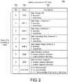
- FIG. 2 is a schematic diagram illustrating information of a first byte for designating enable/disable setting of safety functions defined in the ETG standards.
- Non-Patent Literature 1 discloses information of a first byte for designating enable/disable setting of safety function.
- control words 700 related to the motion safety functions 360 disclosed in Non-Patent Literature 1 include a bit field 702, a name field 704, and a description field 706.
- the respective bits such as a zeroth bit to a seventh bit included in the first byte are disposed in the bit field 702.
- An abbreviated name of the motion safety function 360 correlated with each bit is displayed in the name field 704.
- An official name of each motion safety function 360 and an operating state associated with the flag are displayed in the description field 706.
- the flags are fixed to "0" indicating enabling in a default state with respect to all of the motion safety functions 360.
- Each motion safety function 360 is required to be set to the flag of "0" as a default.
- the flag in each bit from the zeroth bit to the seventh bit is fixed to "0" as a default, and the default state cannot be changed by the user.
- the default state can be changed by the user in a second byte.
- Enabling of the safety function refers to that a function for performing safety control is in an operating state.
- STO, SS1, SS2, SOS, and SSR are “active” when the flag is "0". This indicates that the functions for performing safety control are in an operating state.
- SDIp and SDIn are “disabled” when the flag is "0". This indicates that the motor is prohibited from operating in a positive direction or a negative direction, that is, the functions for performing safety control are in an operating state.
- “disabling” of the safety function refers to that the functions for performing safety control is in a non-operating state.
- STO, SS1, SS2, SOS, and SSR are “deactivated” when the flag is "1". This indicates that the functions for performing safety control are in a non-operating state.
- SDIp and SDIn are “enabled” when the flag is "1". This indicates that the motor is permitted to operate in the positive direction or the negative direction, that is, the functions for performing safety control are in a non-operating state.
- the flags corresponding to all of the motion safety functions 360 are set to "0" as a default regardless of whether or not the motion safety functions 360 is installed.
- the default setting is fixed to enabling, so that the function is enabled.
- the motion safety function 360 is not executed.
- the default setting is fixed to enabling with respect to all of the motion safety functions 360 regardless of whether or not the motion safety function 360 is installed.
- a safety command from the safety controller 200 includes designation information for enabling or disabling the specific motion safety function 360.
- the safety command can be transmitted to the safety driver 300 from the safety controller 200.
- designation information for enabling or disabling the specific motion safety function 360 is included in the safety command, it is possible to change enabling or disabling of the specific motion safety function 360 afterward.
- a user is required to create the safety program 2104 by using a tool such as the support device 500 in order to change the enabled/disabled settings of the specific motion safety function 360 from the default state.
- a tool such as the support device 500
- the efficiency will be reduced.
- the safety program 2104 is required to be created for all the safety drivers 300, which causes a problem that a work amount becomes enormous.
- the support device 500 includes a reception unit 5216 that receives designation, given by a user, of enabling or disabling for each of one or more motion safety functions 360, a generation unit 5212 that automatically generates the safety program 2104 in accordance with the designation of enabling or disabling, received by the reception unit 5216, and a transfer unit 5218 that transfers the safety program 2104 generated by the generation unit 5212 to the safety controller 200.
- the support device 500 may convert source code into object code by performing a build, and transfer the safety program 2104 to the safety controller 200 in the form of the object code, or transfer the safety program 2104 to the safety controller 200 in the form of source code without performing the build.
- the support device 500 may transfer the safety program 2104 to the safety controller 200 via the standard controller 100, or may directly transfer the safety program 2104 to the safety controller 200 without using the standard controller 100.
- the user can use the support device 500 to designate enabling or disabling of each of the motion safety functions 360 for the support device 500.
- the support device 500 automatically generates the safety program 2104 in accordance with enable/disable setting of the motion safety function 360 designated by the user.
- the user can generate the safety program 2104 for designating enabling or disabling of each of the motion safety functions 360 without taking the trouble to write the source code.
- the "designation information” may be any information as long as the information is information for designating enabling or disabling of each of the motion safety functions 360.
- enabling or disabling of each of the motion safety functions 360 is designated by a flag indicated by "0" or "1” by using a bit string in which bits respectively corresponding to the motion safety functions 360 are arranged.
- the user can set a flag in the designation information by using the support device 500 and can thus change enabling or disabling of the specific motion safety function 360 from a default state.
- the flags of all of the motion safety functions 360 are fixed to "0" as a default.
- the user may designate setting of a flag corresponding to each of SS2, SOS, and SDIp to "1" (disabled state) for the support device 500.
- the user designates whether to enable or disable the motion safety function 360 by using the support device 500, and can thus change afterward enabled/disabled settings of the motion safety function 360 defined as a default with the automatically generated safety program 2104.
- the user designates enabling or disabling of the specific motion safety function 360 for the support device 500, and thus the safety program 2104 is generated in accordance with the designation of enabling or disabling and is transferred to the safety controller 200. Consequently, the user can generate the safety program 2104 for designating enabling or disabling of the specific motion safety function 360 without writing source code, and can thus easily set enabling or disabling of the motion safety function 360.
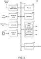
- Fig. 3 is a schematic diagram illustrating a hardware configuration example of the standard controller 100 constituting the control system 1 according to the present embodiment.
- the standard controller 100 includes a processor 102, a main memory 104, a storage 110, a higher-level network controller 106, a field network controller 108, a Universal Serial Bus (USB) controller 120, a memory card interface 112, and a local bus controller 116. These components are connected to each other via a processor bus 118.
- a processor bus 118 a processor bus 118.
- the processor 102 generally corresponds to a calculation processing part executing control calculation related to the standard control 150, and is configured with a central processing unit (CPU) or a graphics processing unit (GPU). Specifically, the processor 102 reads programs (for example, a system program 1102 and the standard control program 1104) stored in the storage 110, loads the programs to the main memory 104, and executes the programs to realize control calculation related to a control target (for example, the safety driver 300 or the servomotor 400) and various processes that will be described later.
- programs for example, a system program 1102 and the standard control program 1104
- the main memory 104 is configured with a volatile storage device such as a dynamic random access memory (DRAM) or a static random access memory (SRAM).
- the storage 110 is configured with a nonvolatile storage device such as a solid state drive (SSD) or a hard disk drive (HDD).
- SSD solid state drive
- HDD hard disk drive
- the storage 110 stores not only the system program 1102 for realizing fundamental functions but also the standard control program 1104 that is created in accordance with a control target.
- the storage 110 stores setting information 1106 for setting a variable or the like.
- the higher-level network controller 106 exchanges data with any information processing device via a higher-level network.
- the field network controller 108 exchanges data with any devices including the safety controller 200 and the safety driver 300 via the field network 2.
- the field network controller 108 of the standard controller 100 functions as a communication master of the field network 2.
- the USB controller 120 exchanges data with the support device 500 or the like via USB connection.
- the memory card interface 112 accepts a memory card 114 that is an example of an attachable and detachable recording medium.
- the memory card interface 112 can record data on the memory card 114 or read the various types of data (a log, trace data, or the like) from the memory card 114.
- the local bus controller 116 exchanges data with any unit connected to the standard controller 100 via a local bus.
- Fig. 3 illustrates the configuration example in which the necessary functions are provided by the processor 102 executing the programs, but some or all of the provided functions may be installed by using a dedicated hardware circuit (for example, an application specific integrated circuit (ASIC) or a field programmable gate array (FPGA)).
- ASIC application specific integrated circuit
- FPGA field programmable gate array
- main parts of the standard controller 100 may be realized by using hardware (for example, an industrial PC based on a general-purpose PC) conforming to a general-purpose architecture.
- a virtualization technique may be used to execute a plurality of operating systems (OSs) having different uses in parallel and also to execute necessary applications on each OS.
- OSs operating systems
- a configuration in which functions of a display device, a support device, or the like are integrated into the standard controller 100 may be used.
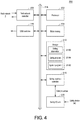
- Fig. 4 is a schematic diagram illustrating a hardware configuration example of the safety controller 200 constituting the control system 1 according to the present embodiment.
- the safety controller 200 includes a processor 202, a main memory 204, a storage 210, a field network controller 208, a USB controller 220, and a safety local bus controller 216. These components are connected to each other via a processor bus 218.
- the processor 202 generally corresponds to a calculation processing part executing control calculation related to the safety control, and is configured with a CPU or a GPU. Specifically, the processor 202 reads programs (for example, a system program 2102 and the safety program 2104) stored in the storage 210, loads the programs to the main memory 204, and executes the programs to realize control calculation for providing the necessary safety function 250 and various processes that will be described later.
- programs for example, a system program 2102 and the safety program 2104
- the safety controller 200 executes the safety program 2104, and thus outputs a safety command including designation information for designating enabling or disabling of the motion safety function 360 of the safety driver 300 to the safety driver 300.
- the designation information included in the safety status 70 of the safety driver 300 may be updated on the basis of the designation information included in the safety command.
- the main memory 204 is configured with a volatile storage device such as a DRAM or an SRAM.
- the storage 210 is configured with a nonvolatile storage device such as an SSD or an HDD.
- the storage 210 stores not only the system program 2102 for realizing fundamental functions but also the safety program 2104 that is created in accordance with the required safety function 250.
- the storage 210 stores setting information 2106 for setting a variable or the like.
- the field network controller 208 exchanges data with any devices including the standard controller 100 and the safety driver 300 via the field network 2.
- the field network controller 208 of the safety controller 200 functions as a communication slave of the field network 2.
- the USB controller 220 exchanges data with an information processing device such as the support device 500 via USB connection.
- the safety local bus controller 216 exchanges data with any safety unit connected to the safety controller 200 via a safety local bus.
- Fig. 4 illustrates a safety I/O unit 230 as an example of the safety unit.
- the safety I/O unit 230 exchanges input and output signals with any safety device 240. More specifically, the safety I/O unit 230 receives an input signal from the safety device 240 such as a safety sensor or a safety switch. Alternatively, the safety I/O unit 230 outputs a command to the safety device 240 such as a safety relay.
- Fig. 4 illustrates the configuration example in which the necessary functions are provided by the processor 202 executing the programs, but some or all of the provided functions may be installed by using a dedicated hardware circuit (for example, an ASIC or an FPGA).
- main parts of the safety controller 200 may be realized by using hardware (for example, an industrial PC based on a general-purpose PC) conforming to a general-purpose architecture.
- Fig. 5 is a schematic diagram illustrating a hardware configuration example of the safety driver 300 and the servomotor 400 constituting the control system 1 according to the present embodiment.
- the safety driver 300 includes a field network controller 302, a control part 310, a drive circuit 330, and a feedback reception circuit 332.
- the field network controller 302 exchanges data with any devices including the standard controller 100 and the safety controller 200 via the field network 2.
- the field network controller 302 of the safety driver 300 functions as a communication slave of the field network 2.
- the control part 310 executes a calculation process required to operate the safety driver 300.
- the control part 310 includes processors 312 and 314, a main memory 316, and a storage 320.
- the processor 312 generally corresponds to a calculation processing part executing control calculation for driving the servomotor 400.
- the processor 314 generally corresponds to a calculation processing part executing control calculation for providing the safety function 250 related to the servomotor 400.
- the processor 314 disables the specific motion safety function 360 in response to the safety command.
- Both of the processors 312 and 314 are configured with CPUs and the like.
- the main memory 316 is configured with a volatile storage device such as a DRAM or an SRAM.
- the storage 320 is configured with a nonvolatile storage device such as an SSD or an HDD.
- the storage 320 stores a servo control program 3202 for realizing servo control 350 that will be described later, a motion safety program 3204 for realizing the motion safety function 360 that will be described later, and setting information 3206 for setting a variable or the like that is open to other devices.
- the safety status 70 for managing enabled/disabled settings of the motion safety function 360 is stored in the setting information 3206.
- Fig. 5 exemplifies a configuration in which the two processors 312 and 314 execute control calculation for different purposes to improve reliability, but the present invention is not limited thereto, and any configuration may be employed as long as the configuration can realize the required safety function 250.
- control calculation corresponding to each of the processors 312 and 314 may be executed.
- Fig. 5 illustrates the configuration example in which the necessary functions are provided by the processors 312 and 314 executing the programs, but some or all of the provided functions may be installed by using a dedicated hardware circuit (for example, an ASIC or an FPGA).
- a dedicated hardware circuit for example, an ASIC or an FPGA
- the drive circuit 330 includes a converter circuit, an inverter circuit, and the like, generates power with designated voltage, current, and phase in response to a command from the control part 310, and supplies the power to the servomotor 400.
- the feedback reception circuit 332 receives a feedback signal from the servomotor 400, and outputs the reception result to the control part 310.
- the servomotor 400 typically includes a three-phase AC motor 402 and an encoder 404 provided at a rotation shaft of the three-phase AC motor 402.
- the three-phase AC motor 402 is an actuator that receives power supplied from the safety driver 300 and generates torque.
- Fig. 5 illustrates the three-phase AC motor as an example, but the present invention is not limited thereto, and a DC motor may be used, and a single-phase AC motor or a multi-phase AC motor may be used.
- An actuator that generates torque along a straight line, such as a linear servo, may be used.
- the encoder 404 outputs a feedback signal (typically, a pulse signal corresponding to a rotation speed) corresponding to the rotation speed of the three-phase AC motor 402.
- a feedback signal typically, a pulse signal corresponding to a rotation speed
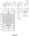
- Fig. 6 is a schematic diagram illustrating a hardware configuration example of the support device 500 constituting the control system 1 according to the present embodiment.
- the support device 500 is implemented by using hardware (for example, a general-purpose PC) conforming to a general-purpose architecture as an example.
- the support device 500 includes a processor 502, a main memory 504, an input part 506, an output part 508, a storage 510, an optical drive 512, and a USB controller 520. These components are connected to each other via a processor bus 518.
- the processor 502 is configured with a CPU or a GPU, reads programs (for example, an OS 5102 and a support program 5104) stored in the storage 510, loads the programs to the main memory 504, and executes the programs to perform various processes that will be described later.
- the processor 502 has a function of a computer executing the support program 5104.
- the processor 502 has the function of the generation unit 5212 illustrated in Fig. 1 , and generates a safety source program 5112 in accordance with designation of enabling or disabling of the motion safety function 360 received from a user.
- the main memory 504 is configured with a volatile storage device such as a DRAM or an SRAM.
- the storage 510 is configured with a nonvolatile storage device such as an HDD or an SSD.
- the storage 510 stores not only the OS 5102 for realizing fundamental functions but also the support program 5104 for providing functions of the support device 500.
- the support program 5104 is executed by a computer connected to the control system 1 to implement the support device 50 according to the present embodiment.
- the support program 5104 includes an enable/disable setting support program 90.
- the support device 500 executes the enable/disable setting support program 90 to receive designation of enabling or disabling of the motion safety function 360 from a user, and also generates the safety source program 5112 by using the processor 502 in accordance with the received designation of enabling or disabling.
- the storage 510 stores project data 5106 that is created by the user in a development environment that is provided by executing the support program 5104.
- the support device 500 provides a development environment in which setting on each device included in the control system 1 and creation of a program executed by each device can be integrally performed.
- the project data 5106 includes data generated by using such an integrated development environment.
- the project data 5106 includes a standard control source program 5108, standard controller setting information 5110, a safety source program 5117, safety controller setting information 5114, and safety driver setting information 5116.
- the standard control source program 5108 is converted into object codes that are then transmitted to the standard controller 100 to be stored in the standard control program 1104 (refer to Fig. 3 ).
- the standard control source program 5108 may be transmitted to the standard controller 100 without being converted into object codes.
- the standard controller setting information 5110 is also transmitted to the standard controller 100 to be stored in the setting information 1106 (refer to Fig. 3 ).
- the safety source program 5117 is converted into object codes that are then transmitted to the safety controller 200 to be stored in the safety program 2104 (refer to Fig. 4 ).
- the safety source program 5117 may be transmitted to the safety controller 200 without being converted into object codes.
- the safety controller setting information 5114 is also transmitted to the safety controller 200 to be stored in the setting information 2106 (refer to Fig. 4 ).
- the safety driver setting information 5116 is transmitted to the safety driver 300 to be stored in the setting information 3206 (refer to Fig. 5 ).
- the input part 506 is an interface that receives information that is input with a keyboard or a mouse, and has the function of the reception unit 5216 illustrated in Fig. 1 . Particularly, the input part 506 receives designation, given by the user, of enabling or disabling of the motion safety function 360.
- the output part 508 is configured with a display, various indicators, a printer, and the like, and outputs a processing result or the like from the processor 502.
- the USB controller 520 has the function of the transfer unit 5218 illustrated in Fig. 1 , and exchanges data with the standard controller 100 or the like through USB connection. Particularly, the USB controller 520 transfers the safety source program 5112 that is automatically generated by the processor 502 to the safety controller 200. The USB controller 520 may transfer the safety source program 5112 to the safety controller 200 via the standard controller 100, and may transfer the safety source program 5112 to the safety controller 200 without using the standard controller 100.
- the support device 500 has the optical drive 512, and a program is read from a recording medium 514 (for example, an optical recording medium such as a digital versatile disc (DVD)) that stores computer-readable programs in a non-transitory manner and is installed in the storage 510 or the like.
- a recording medium 514 for example, an optical recording medium such as a digital versatile disc (DVD)
- DVD digital versatile disc
- the support program 5104 or the like executed by the support device 500 may be installed via the computer-readable recording medium 514, or may be downloaded from a server device or the like on the network to be installed.
- the functions provided by the support device 500 according to the present embodiment may be realized in a form of using some modules provided by the OS.
- Fig. 6 illustrates the configuration example in which the necessary functions of the support device 500 are provided by the processor 502 executing the programs, but some or all of the provided functions may be installed by using a dedicated hardware circuit (for example, an ASIC or an FPGA).
- a dedicated hardware circuit for example, an ASIC or an FPGA.
- the support device 500 may be detached from the standard controller 100.
- FIG. 7 is a schematic diagram illustrating an example of function sharing in the control system 1 according to the present embodiment.
- the safety driver 300 executes the servo control 350 in relation to the standard control 150 executed by the standard controller 100.
- the standard control 150 includes a process of cyclically calculating commands for driving the servomotor 400 according to a user program that is set in a control target in advance.
- the servo control 350 includes control for driving the servomotor 400 in response to commands that are cyclically calculated through the standard control 150 and a process of acquiring and outputting a state value indicating an operation state of the servomotor 400.
- the servo control 350 is performed by the processor 312 (refer to Fig. 5 ) of the safety driver 300.
- the safety driver 300 provides the motion safety function 360 in correspondence to the safety function 250 provided by the safety controller 200.
- the motion safety function 360 is realized by the processor 314 (refer to Fig. 5 ) of the safety driver 300.
- the safety function 250 When a predefined condition is established, the safety function 250 enables the predefined safety function 250 on the basis of a state value stored in the standard control 150 executed by the standard controller 100, a state value indicated by a signal from the safety device 240, a state value stored in the safety driver 300, and the like.
- the process of enabling the predefined safety function 250 includes, for example, output of a safety command for the safety driver 300 or output of a safety command for the safety device 240 (for example, a safety relay related to the supply of power to a specific device is turned off).
- the safety driver 300 executes the motion safety program 3204 to realize the designated motion safety function 360 in response to a safety command from the safety controller 200.
- the motion safety function 360 that can be executed is defined in advance in each safety driver 300.
- a process of intervening in the control of the servomotor 400 based on the servo control 350 to interrupt the supply of power to the servomotor 400, or a process of monitoring whether or not a state value of the control of the servomotor 400 based on the servo control 350 is within a predefined restriction range is executed.
- the motion safety program 3204 enables or disables each motion safety function 360 in accordance with enable/disable setting of a safety function designated by designation information included in the safety status 70.
- Fig. 8 is a sequence diagram illustrating an example of a process procedure related to the safety functions 250 of the safety driver 300 of the control system 1 according to the present embodiment.
- a command is cyclically calculated through the standard control 150 of the standard controller 100 and is output to the safety driver 300 (servo control 350) (sequence SQ2).
- the servo control 350 of the safety driver 300 drives the servomotor 400 in response to the command from the standard control 150 (sequence SQ4).
- the safety controller 200 When a safety event from the safety device 240 (for example, a safety sensor) occurs at a certain timing (sequence SQ6), the safety controller 200 outputs a safety command to the safety driver 300 (motion safety function 360) (sequence SQ8).
- the motion safety function 360 of the safety driver 300 enables the designated safety function 250 in response to the safety command (sequence SQ10).
- a command corresponding to the enabled safety function 250 is calculated and output from the standard control 150 of the standard controller 100 (sequence SQ12).
- the safety driver 300 motion safety function 360
- the safety driver 300 motion safety function 360
- the safety driver 300 can drive the servomotor 400 in response to a command from the standard controller 100 (standard control 150), and can also realize the motion safety function 360 for the safety controller 200 (safety function 250) in response to a command for enabling the safety function 250.
- Fig. 9 is a diagram illustrating an example of the motion safety function 360 provided by the control system 1 according to the present embodiment.
- Fig. 9(A) illustrates an example of a behavior of the servomotor 400 corresponding to STO
- Fig. 9(B) illustrates an example of a behavior of the servomotor 400 corresponding to SS1.
- a safety command (STO) is output at time point t1 in a state in which the servomotor 400 is being operated at a certain rotation speed
- the safety driver 300 interrupts the supply of power to the servomotor 400 to make torque generated by the servomotor 400 zero.
- the servomotor 400 is rotated by the inertia and is then stopped.
- the servomotor 400 may be immediately stopped.
- a safety command (SS1) is output at time point t1 in a state in which the servomotor 400 is being operated at a certain rotation speed
- the safety driver 300 reduces the rotation speed at a predefined acceleration.
- the safety driver 300 may perform power recovery (that is, regeneration) from the servomotor 400.
- the safety driver 300 interrupts the supply of power to the servomotor 400 to make torque generated by the servomotor 400 zero.
- the same state as the state corresponding to STO illustrated in Fig. 9(A) is brought.
- a safety function that causes more safe stoppage is selected as appropriate in accordance with characteristics or the like of a facility that is mechanically connected to the servomotor 400.
- Non-Patent Literature 1 described above defines not only the motion safety functions illustrated in Figs. 9(A) and 9(B) but also a plurality of motion safety functions. Settings for defining a behavior of the servomotor 400 are necessary to realize each motion safety function.
- safety communication can be performed through data communication and the logical connection 4.
- installation examples of standard control and safety control using each type of communication will be described.
- Fig. 10 is a schematic diagram illustrating installation examples of standard control and safety control in the control system 1 according to the present embodiment.
- Fig. 10 illustrates an example of the control system 1 including the single safety driver 300 in addition to the standard controller 100 and the safety controller 200.
- the standard controller 100 includes a data communication layer 170 and an I/O management module 172 as principal functional constituents.
- the safety controller 200 includes a data communication layer 270, an I/O management module 272, a logical connection layer 276, and a safety function state management engine 278 as principal functional constituents.
- the safety driver 300 includes a data communication layer 370, a logical connection layer 376, and a motion safety function state management engine 378, a servo control execution engine 352, and a motion safety function execution engine 362 as principal functional constituents.
- the data communication layer 170, the data communication layer 270, and the data communication layer 370 are used to transfer the communication frame 600 on the field network 2.
- the logical connection layer 276 of the safety controller 200 and the logical connection layer 376 of the safety driver 300 exchange safety communication frames 630.
- the logical connection layer 276 and the logical connection layer 376 exchange commands and data by using the safety communication frame 630 included in the communication frame 600 according to a protocol (FSoE in the present embodiment) for establishing the logical connection 4.
- the safety controller 200 includes an establishment module 277 for establishing the logical connection 4 with the safety driver 300 via the logical connection layer 276.
- the I/O management module 172 exchanges signals with a control target to update process data 174.
- the standard control program 1104 executed in the standard controller 100 executes control calculation by referring to the process data 174, and updates the process data 174 as an execution result of the control calculation.
- the I/O management module 272 exchanges signals with the safety device 240 to update process data 274.
- the safety program 2104 executed in the safety controller 200 executes control calculation by referring to the process data 274 and the safety function state management engine 278, and updates the process data 274 or outputs an internal command to the safety function state management engine 278 on the basis of an execution result of the control calculation.
- the safety function state management engine 278 generates a safety command for enabling or disabling the specific motion safety function 360 for the specific safety driver 300 in accordance with the execution result of the control calculation performed by the safety program 2104.
- the logical connection layer 276 exchanges necessary commands and data with the logical connection layer 376 of the target safety driver 300 by using the safety communication frames 630 in response to the command from the safety function state management engine 278.
- the servo control execution engine 352 executes control calculation related to servo control by referring to process data 374 and information regarding a feedback signal acquired via the feedback reception circuit 332.
- the servo control execution engine 352 updates the process data 374 and outputs an internal command to the drive circuit 330 on the basis of an execution result of the control calculation.
- the drive circuit 330 drives the servomotor 400 in response to the command from the servo control execution engine 352.
- the motion safety function state management engine 378 manages a state of the motion safety function 360 in response to a safety command from the safety controller 200.
- the safety status 70 is stored in the motion safety function state management engine 378.
- the motion safety function state management engine 378 outputs an internal command to the motion safety function execution engine 362 according to designation information included in the safety status 70.
- the motion safety program 3204 is executed to realize the designated motion safety function 360.
- the logical connection layer 376 exchanges necessary commands and data with the logical connection layer 276 of the safety controller 200 by using the safety communication frames 630 in response to a command from the motion safety function state management engine 378.
- Fig. 11 is a schematic diagram illustrating an example of transition in enabling or disabling of the motion safety function 360 according to the present embodiment.
- the flags corresponding to all of the motion safety functions 360 are set to "0" as a default regardless of whether or not the motion safety functions 360 is installed.
- the flags of all bits included in the safety status 70 are set to "0" as a default.
- the safety program 2104 is automatically generated in accordance with the designation of enabling or disabling.
- the safety controller 200 executes the safety program 2104 to transmit a safety command including the information regarding the designation, given by the user, of enabling or disabling of the motion safety function 360 to the safety driver 300.
- the designation information included in the safety status 70 is updated according to the designation information included in the safety command. More specifically, the designation information included in the safety status 70 is overwritten to be the same as the designation information included in the safety command.
- setting of enabling or disabling of the specific motion safety function 360 can be changed from a default state by using a safety command.
- FIG. 12 is a schematic diagram illustrating an enable/disable setting portion for the safety functions in the safety program 2104 according to the present embodiment.
- source code for designating enabling or disabling of the motion safety function 360 is written in a part of the safety program 2104 for each of one or a plurality of safety drivers 300 included in the control system 1.
- TRUE is designated for SS2, SOS, and SDIp with respect to the safety driver 300 correlated with the identification code "E010”.
- TRUE is designated for SS1, SOS, SSR, and SDIn with respect to the safety driver 300 correlated with the identification code "E011”.
- a flag is set to "1" in each bit included in designation information with respect to the motion safety function 360 for which "TRUE” is designated.
- designation information for designating flags respectively corresponding to SS2, SOS, and SDIp as “1” with respect to the safety driver 300 correlated with “E010” is included in a safety command
- designation information for designating flags respectively corresponding to SS1, SOS, SSR, and SDIn as "1” with respect to the safety driver 300 correlated with "E011” is included in a safety command.
- such source code is required to be written through an input operation of a user, but, in the present embodiment, the user only designates enable/disable setting of the safety function in the support device 500, and thus the safety program 2104 in which the same source code is written is automatically generated.
- the safety program 2104 that is automatically generated by the support device 500 cannot be edited by the user.
- the generated safety program 2104 is not displayed on a display part of the support device 500 or the like, and the user cannot recognize details of the program and cannot edit the program either.
- the generated safety program 2104 may be displayed on the display part of the support device 500 or the like, but the user cannot edit details of the program.
- the safety program 2104 generated by the support device 500 is not able to be edited by the user, it is possible to prevent the occurrence of a problem that set details of enabling or disabling of a safety function designated for the support device 500 by the user do not coincide with set details in the safety program 2104 generated by the support device 500.
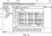
- Figs. 13 and 14 are diagrams illustrating examples of user interfaces for setting enabling or disabling of the motion safety function 360 provided by the support device 500 according to the present embodiment.
- Fig. 15 is a diagram illustrating an example of a user interface for setting a variable in the safety program 2104 provided by the support device 500 according to the present embodiment.
- the user may execute the support program 5104 (enable/disable setting support program 90) in the support device 500 to display screens related to user interfaces as illustrated in Figs. 13 to 15 .
- a multiview explorer field 610 is provided on the left of a screen related to a user interface 601.
- the multiview explorer field 610 includes a switching switch 612 for designating a development target program.
- "new_SafetyCPU0" corresponding to the safety program 2104 is designated in the switching switch 612.
- the multiview explorer field 610 includes a configurations and setup switch 614 for setting a constituent connected to a network in the control system 1.
- a lower-level layer developed by the configurations and setup switch 614 includes an enable/disable setting icon 616 for designating enabling or disabling of the motion safety function 360 and an I/O map icon 618 for mapping a variable referred to by the safety program 2104.
- the "variable” includes data and a container or a storage region in which the data is stored.
- the variable referred to by the safety program 2104 is correlated with a state value of the servomotor 400 or the like, and each motion safety function 360 is realized according to the state value correlated with the variable.
- the enable/disable setting icon 616 is provided in each of one or a plurality of safety drivers 300 connected to the control system 1, and, in this example, the enable/disable setting icon 616 corresponding to the safety driver 300 of Node10 is selected.
- a screen 620 for designating enabling or disabling of the motion safety function 360 is displayed at the center of the screen related to the user interface 601.
- the screen 620 includes a number field 622 and a flag field 624.
- numbers are shown for the respective motion safety functions 360 in order from the first bit in the same order as the designation information included in the safety status 70.
- all information corresponding to the fourth bit is "Reserved".
- the flag field 624 is provided with a check box that can be checked by the user.
- the user designates "TRUE" in the source code of the safety program 2104, the user may uncheck the check box of the flag field 624.
- the flag is set to "1" in the designation information included in the safety command.
- the flag is set to "0" in the designation information included in the safety command.
- the user can change the default state in the second byte of the safety status 70, and, as illustrated in Fig. 13 , the user can easily perform enable/disable setting in the second byte by checking or unchecking the check box of the flag field 624.
- SS2, SOS, and SDIp are unchecked in the check box of the flag field 624.
- the flags corresponding to SS2, SOS, and SDIp are designated as "1".
- the user designates enabling or disabling of each motion safety function 360 in the safety driver 300, and then selects a transfer icon 680, and thus the safety program 2104 corresponding to the designation of enabling or disabling can be generated.
- the generated safety program 2104 is transferred to the safety controller 200.
- the screen is switched to a screen related to a user interface 603.
- a screen 650 for mapping a variable to each motion safety function 360 is displayed at the center of the screen related to the user interface 603.
- the screen 650 includes a port field 652, a variable field 654, and a variable comment field 656.
- Each motion safety function 360 installed in the selected safety driver 300 (Node10 in this example) is shown in the port field 652.
- a variable correlated with each motion safety function 360 is shown in the variable field 654.
- a comment to the variable correlated with each motion safety function 360 is shown in the variable comment field 656.
- variable field 654 and the variable comment field 656 become blank in the screen related to the user interface 603 illustrated in Fig. 15 .
- the variable field 654 and the variable comment field 656 corresponding to SS2 and SOS become blank.
- the support device 500 prohibits the use of the variable referred to by the safety program 2104 related to the specific motion safety function 360. Consequently, it is possible to prevent a situation in which the user unintentionally sets a variable referred to by the safety program 2104 related to the disabled motion safety function 360.
- Fig. 16 is a flowchart for describing a safety enable/disable program generation process executed by the support device 500 according to the present embodiment.
- the support device 500 determines whether or display of a safety function enable/disable setting screen has been received (S502). In a case where display of safety function enable/disable setting screen has not been received (NO in S502), the support device 500 finishes the present process.
- the support device 500 displays the safety function enable/disable setting screen as illustrated in Fig. 13 (S504).
- the support device 500 determines whether or not safety function enable/disable setting has been received (S506). Specifically, the support device 500 whether the check box of the flag field 624 has been checked or unchecked by a user in the screen related to the user interface 601 illustrated in Fig. 13 . In a case where safety function enable/disable setting has not been received (NO in S506), the support device 500 repeatedly performs the process in S506 until enable/disable setting is received.
- the support device 500 determines whether or not an instruction for transfer has been received (S508). Specifically, the support device 500 determines whether or not the transfer icon 680 has been selected in the screen related to the user interface 601 illustrated in Fig. 13 . In a case where an instruction for transfer has not been received (NO in S508), the support device 500 returns to the process in S506.
- the support device 500 determines whether or not a variable has been mapped to the motion safety function 360 set to be disabled (S510). In a case where a variable has not been mapped to the motion safety function 360 set to be disabled (NO in S510), the support device 500 finishes the present process.
- the support device 500 cancels the variable corresponding to the motion safety function 360 set to be disabled (S512), and provides a notification of cancelation (S514).
- the support device 500 provides a notification that the variable correlated with the disabled specific motion safety function 360 has been canceled in the output window 670 illustrated in Fig. 14 .
- the support device 500 maps a variable for generating the safety program 2104 to the safety function set to be disabled (S516).
- a unique name that is not set by the user is used as a variable name. If the same name is used for the variable name, the name may be identified by adding a subscript such as a number.
- the support device 500 generates the safety program 2104 by using the variable mapped in S516 (S518). In a case where a variable for generating the safety program 2104 has already been mapped to a safety function set to be disabled, the support device 500 may generate the safety program 2104 by using the variable.
- the support device 500 prohibits mapping of a variable to the motion safety function 360 set to be disabled (S520), and transfers the generated safety program 2104 to the safety controller 200 (S522).
- the support device 500 may convert source code into object code by performing a build, and transfer the safety program 2104 to the safety controller 200 in the form of the object code, or transfer the safety program 2104 to the safety controller 200 in the form of source code without performing the build.
- the support device 500 may transfer the safety program 2104 to the safety controller 200 via the standard controller 100, or may directly transfer the safety program 2104 to the safety controller 200 without using the standard controller 100. Thereafter, the support device 500 finishes the present process.
- the support device 500 generates the safety program 2104 in accordance with designation, given by the user, of enabling or disabling of the specific motion safety function 360, and transfers the generated safety program 2104 to the safety controller 200. Consequently, the user can generate the safety program 2104 for designating enabling or disabling of the specific motion safety function 360 without writing source code, and can thus easily set enabling or disabling of the motion safety function 360.
- the support device 500 In response to designation of disabling of the specific motion safety function 360, the support device 500 prohibits the use of the variable referred to by the safety program 2104 related to the specific motion safety function 360. Consequently, it is possible to prevent a situation in which the user unintentionally sets a variable referred to by the safety program 2104 related to the disabled motion safety function 360.
- the support device 500 can notify the user that a variable referred to by the safety program 2104 related to the disabled motion safety function 360 is prohibited from being used.
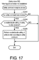
- Fig. 17 is a flowchart for describing a safety command reception process executed by the safety driver 300 according to the present embodiment.
- the safety driver 300 executes a safety command reception process illustrated in Fig. 17 after connection in the field network 2 is established and the logical connection 4 is established.
- the safety driver 300 determines whether or not a safety command has been received from the safety controller 200 (S322). In a case where a safety command has not been received (NO in S322), the safety driver 300 finishes the present process.
- the safety driver 300 determines whether or not enable/disable setting of the motion safety function 360 is included in the safety command (S324). In other words, the safety driver 300 determines whether or not designation of enabling or disabling of the safety function that is given by the user and is input from the support device 500 is included in the safety command that is transferred due to execution of the safety program 2104 automatically generated by the support device 500.
- the safety driver 300 performs enable/disable setting of the specific motion safety function 360 according to designation information included in the safety command (S326). For example, as illustrated in Fig. 11 , in a case where the safety command including designation information indicating that SS2 and SOS are disabled and SDIp is enabled is received, the safety driver 300 also disables SS2 and SOS and enables SDIp in the designation information included in the safety status 70. Thereafter, the safety driver 300 finishes the present process.
- the safety driver 300 performs enable/disable setting of the motion safety function 360 in response to a safety command that is received after the logical connection 4 is established. Consequently, the user can change enabling or disabling of the specific motion safety function 360 from a default state by using the safety command.
- the support device 500 receives checking or unchecking of the check box of the flag field 624 with respect to the motion safety function 360 (SSR in this example) that is not installed in the safety driver 300, but is not limited thereto.
- the support device 500 may not receive checking or unchecking of the check box of the flag field 624 with respect to the motion safety function 360 that is not installed in the safety driver 300.
- the support device 500 does not need to display the check box of the flag field 624 with respect to the motion safety function 360 that is not installed in the safety driver 300, and may bring the motion safety function into a non-operating state even if the check box is displayed.
- the support device 500 receives enable/disable setting of the motion safety function 360 for each safety driver 300, but is not limited thereto. For example, since a user may want to make enabled/disabled settings of the motion safety function 360 common to the plurality of safety drivers 300, the support device 500 may provide a user interface for receiving enabled/disabled settings of the motion safety function 360 common to the plurality of safety drivers 300.
- the support device 500 may collectively generate the safety programs 2104 including the enabled/disabled settings of the motion safety function 360 having the same details for the plurality of safety drivers 300, and collectively transfer the generated safety programs 2104 to the plurality of respective safety drivers 300 when the transfer icon 680 is selected.
- the present embodiment described above includes the following technical concept.
- a control system (1) including:
- the control system according to Configuration 1, in which the support device provides a user interface (601) for receiving the designation of enabling or disabling of each of the at least one or more safety functions via the reception unit.
- the control system according to Configuration 1 or 2, in which the support device provides a user interface (601) for receiving the designation of enabling or disabling of each of the at least one or more safety functions via the reception unit with respect to a specific drive device selected from among a plurality of the drive devices.
- a user designates enabling or disabling of the specific motion safety function 360 for the support device 500, and thus the safety program 2104 is generated in accordance with the designation of enabling or disabling and is transferred to the safety controller 200. Consequently, the user can generate the safety program 2104 for designating enabling or disabling of the specific motion safety function 360 without writing source code, and can thus easily set enabling or disabling of the motion safety function 360.
Landscapes
- Physics & Mathematics (AREA)
- General Physics & Mathematics (AREA)
- Engineering & Computer Science (AREA)
- Automation & Control Theory (AREA)
- Programmable Controllers (AREA)
- Safety Devices In Control Systems (AREA)
Abstract
Description
- The present invention relates to a control system, a support device included in a control system, and a support program.
- In many manufacturing sites, the introduction of safety systems is progressing in order to use facilities and machines safely. The safety systems are used to provide safety functions conforming to international standards, and include safety components such as a safety controller, a safety sensor, a safety switch, and a safety relay.
- A safety system is also required to provide the safety function to a drive device that drives a servomotor or the like for driving a facility or a machine. In a safety system, Ethernet for Control Automation Technology (EtherCAT) (registered trademark) may be employed as a network for exchanging data, and Non-Patent Literature 1 discloses some provisions regarding safety functions in the standards of the EtherCAT Technology Group (ETG) which is an organization related to EtherCAT.
- [Non-Patent Literature 1]
- Safety Drive Profile Generic Safety Drive Profile for adjustable speed electrical power drive systems that are suitable for use in safety-related application PDS(SR) Document: ETG.6100.2S(R) V1.2.0
- According to the provisions disclosed in
Non-Patent Literature 1, all safety functions executed by a drive device are set in advance to be enabled as a default. More specifically, in designation information for designating enabling or disabling of the safety functions, all flags assigned to respective bits of a first byte are fixed to flags indicating enabling. - However, in the actual use, there may be cases where enabled/disabled settings of the safety functions are required to be changed depending on work details in a process, such as enabling the safety functions in one process and disabling the safety functions in another process. In such a case, a user is required to separately prepare a program for changing the enabled/disabled settings of the safety functions from the default state, which may increase an amount of work. In the programming work, since source code is required to be written, there is a risk that the user will unintentionally write erroneous setting details.
- The present invention has been made to solve the above problems, and an objective thereof is to facilitate setting of enabling or disabling of safety functions.
- According to an example of the present disclosure, there is provided a control system. The control system includes a drive device that has at least one or more safety functions and drives a motor; a controller that outputs a command related to the at least one or more safety functions to the drive device according to a safety program; and a support device that supports development of the safety program. The safety program includes information for disabling a specific safety function among the at least one or more safety functions. The support device includes a reception unit that receives designation, given by a user, of enabling or disabling of each of the at least one or more motion safety functions, a generation unit that generates the safety program in accordance with the designation of enabling or disabling received by the reception unit, and a transfer unit that transfers the safety program generated by the generation unit to the controller.
- According to this disclosure, the user designates enabling or disabling of a specific safety function for the support device, and thus the safety program is generated in accordance with the designation of enabling or disabling and is transferred to the controller. Consequently, the user can generate the safety program for designating enabling or disabling of the specific safety function without writing source code, and can easily set enabling or disabling of the safety function.
- In the above disclosure, the support device provides a user interface for receiving the designation of enabling or disabling of each of the at least one or more safety functions via the reception unit.
- According to this disclosure, the user can designate enabling or disabling of each of the at least one or more safety functions by using the user interface provided by the support device.
- In the above disclosure, the support device provides a user interface for receiving the designation of enabling or disabling of each of the at least one or more safety functions via the reception unit for a specific drive device selected from among a plurality of the drive devices.
- According to this disclosure, the user can designate enabling or disabling of each of the at least one or more safety functions by using the user interface provided by the support device for the specific drive device selected from among a plurality of the drive devices.
- In the above disclosure, in response to designation of disabling of the specific safety function among the at least one or more safety functions, the support device prohibits use of a variable referred to by the safety program related to the specific safety function.
- According to this disclosure, it is possible to prevent a situation in which the user unintentionally sets the variable referred to by a program related to the disabled safety function.
- In the above disclosure, the support device provides a notification of prohibition of use of the variable.
- According to this disclosure, it is possible to notify the user that the variable referred to by a program related to the disabled safety function is prohibited from being used.
- In the above disclosure, the safety program generated by the generation unit is uneditable by the user.
- According to this disclosure, since the safety program generated by the support device is not able to be edited by the user, it is possible to prevent the occurrence of a problem that set details of enabling or disabling of a safety function designated for the support device by the user do not coincide with set details in the safety program generated by the support device.
- According to another example of the present disclosure, there is provided a support device that supports development of a safety program related to at least one or more safety functions executed by a controller controlling a drive device driving a motor. The safety program includes information for disabling a specific safety function among the at least one or more safety functions. The support device includes a reception unit that receives designation, given by a user, of enabling or disabling of each of the at least one or more safety functions; a generation unit that generates the safety program in accordance with the designation of enabling or disabling received by the reception unit; and a transfer unit that transfers the safety program generated by the generation unit to the controller.
- According to this disclosure, the user designates enabling or disabling of a specific safety function for the support device, and thus the safety program is generated in accordance with the designation of enabling or disabling and is transferred to the controller. Consequently, the user can generate the safety program for designating enabling or disabling of the specific safety function without writing source code, and can thus easily set enabling or disabling of the safety function.
- According to still another example of the present disclosure, there is provided a support program for supporting development of a safety program related to at least one or more safety functions executed by a controller controlling a drive device driving a motor. The support program includes information for disabling a specific safety function among the at least one or more safety functions. The support program causes a computer to execute receiving designation, given by a user, of enabling or disabling of each of the at least one or more safety functions; generating the safety program in accordance with the received designation of enabling or disabling; and transferring the generated safety program to the controller.
- According to the present invention, it is possible to facilitate setting of enabling or disabling of safety functions.
-
-
Fig. 1 is a schematic diagram illustrating an application example of a control system according to the present embodiment. -
Fig. 2 is a schematic diagram illustrating information of a first byte for designating enable/disable setting of safety functions defined in the ETG standards. -
Fig. 3 is a schematic diagram illustrating a hardware configuration example of a standard controller constituting the control system according to the present embodiment. -
Fig. 4 is a schematic diagram illustrating a hardware configuration example of a safety controller constituting the control system according to the present embodiment. -
Fig. 5 is a schematic diagram illustrating a hardware configuration example of a safety driver and a servomotor constituting the control system according to the present embodiment. -
Fig. 6 is a schematic diagram illustrating a hardware configuration example of a support device constituting the control system according to the present embodiment. -
Fig. 7 is a schematic diagram illustrating an example of function sharing in the control system according to the present embodiment. -
Fig. 8 is a sequence diagram illustrating an example of a process procedure related to the safety functions of the safety driver of the control system according to the present embodiment. -
Fig. 9 is a diagram illustrating an example of a motion safety function provided by the control system according to the present embodiment. -
Fig. 10 is a schematic diagram illustrating installation examples of standard control and safety control in the control system according to the present embodiment. -
Fig. 11 is a schematic diagram illustrating an example of transition in enabling or disabling of the motion safety function according to the present embodiment. -
Fig. 12 is a schematic diagram illustrating an enabled/disabled setting portion for the safety functions in a safety program according to the present embodiment. -
Fig. 13 is a diagram illustrating an example of a user interface for setting enabling/disabling of the motion safety function provided by the support device according to the present embodiment. -
Fig. 14 is a diagram illustrating an example of a user interface for setting enabling/disabling of the motion safety function provided by the support device according to the present embodiment. -
Fig. 15 is a diagram illustrating an example of a user interface for setting variables in the safety program provided by the support device according to the present embodiment. -
Fig. 16 is a flowchart for describing a safety enable/disable program generation process executed by the support device according to the present embodiment. -
Fig. 17 is a flowchart for describing a safety command reception process executed by the safety driver according to the present embodiment. - An embodiment of the present invention will be described with reference to the drawings. The same or similar portions in the drawings will be given the same reference numeral, and description thereof will not be repeated.
- <A. Application example>
- First, an application example of the present invention will be described.
-
Fig. 1 is a schematic diagram illustrating an application example of acontrol system 1 according to the present embodiment. Thecontrol system 1 according to the present embodiment provides not only safety functions defined in, for example, IEC 61508 but also some safety functions related to a drive device, such as safe torque off (STO), safe stop 1 (SS1), safe stop 2 (SS2), and safe operation stop (SOS) defined in Non-Patent Literature 2 ("IEC 61800-5-2: 2016 Adjustable speed electrical power drive systems - Part 5-2: Safety requirements - Functional", International Electrotechnical Commission, 2016-04-18). - With reference to
Fig. 1 , thecontrol system 1 generally includes astandard controller 100, and asafety controller 200 and one or a plurality of safety drivers (safety servo drivers) 300 connected to thestandard controller 100 via afield network 2. Each of thesafety drivers 300 drives aservomotor 400 electrically connected thereto. Theservomotor 400 is only an example, and any type of motor may be used. An entity of thesafety driver 300 may be a servo driver, and may be a general-purpose inverter device. In the following description, thesafety driver 300 will be described as an example of a "drive device". - The
standard controller 100 executes standard control (standard control 150 that will be described later) on control targets including theservomotor 400 according to a standard control program (astandard control program 1104 that will be described later) that is created in advance. Typically, thestandard controller 100 executes control calculation in a cyclic manner in accordance with input signals from one or a plurality of sensors (not illustrated) to calculate commands for an actuator such as theservomotor 400 in a cyclic manner. - The
safety controller 200 corresponds to a "controller", and transmits a safety command related to an operation of a safety function (asafety function 250 that will be described later) to thesafety driver 300 according to a safety program (asafety program 2104 that will be described later). Thesafety controller 200 executes monitoring and control calculation for realizing thesafety function 250 for a control target in a cyclic manner separately from thestandard controller 100. - The
safety controller 200 may receive an input signal from anysafety device 240 and/or may output a command to anysafety device 240. Thesafety program 2104 is created in advance by a user by using a development environment provided by asupport device 500 that is communicatively connected to thesafety controller 200, and is transferred to thesafety controller 200. - The
safety driver 300 supplies power to theservomotor 400 in response to a command from thestandard controller 100 to drive theservomotor 400. Thesafety driver 300 calculates a rotation position, a rotation speed, a rotation acceleration, and a generated torque of theservomotor 400 in a cyclic manner on the basis of a feedback signal or the like from theservomotor 400. - The
safety driver 300 executes a predetermined motion safety function (amotion safety function 360 that will be described later) related to driving of theservomotor 400 in response to a safety command from thesafety controller 200. More specifically, thesafety driver 300 provides state information necessary for a safety function to thesafety controller 200, and executes a motion safety program (amotion safety program 3204 that will be described later) corresponding to a required safety function to adjust or interrupt power supplied to theservomotor 400. - The
servomotor 400 has a motor (a three-phase AC motor 402 that will be described later) that is rotated by receiving power from thesafety driver 300, and outputs a detection signal as a feedback signal from an encoder (anencoder 404 that will be described later) coupled to a rotation shaft of the motor to thesafety driver 300. - The
support device 500 supports development on thestandard controller 100 side and development on thesafety controller 200 side. More specifically, thesupport device 500 supports development of a standard control program (thestandard control program 1104 that will be described later) executed by thestandard controller 100, setting related to thestandard control 150, and the like as the development on thestandard controller 100 side. Thesupport device 500 supports development of a safety program (thesafety program 2104 that will be described later) executed by thesafety controller 200, setting related to thesafety function 250, and the like as the development on thesafety controller 200 side. Thesupport device 500 combines one or more pieces of instruction information with each other to provide development environments (a program creation/editing tool, a parser, a compiler, and the like) for generating a program to a user. - In the present specification, "device" is a general term for devices that can perform data communication with other devices via any network such as the
field network 2. In thecontrol system 1 according to the present embodiment, the "device" includes thestandard controller 100, thesafety controller 200, and thesafety driver 300. - In the present specification, the terms "standard control" and "safety control" are used in contrast. "Standard control" is a general term for processes for controlling a control target according to a predefined requirement specification. On the other hand, "safety control" is a general term for processes for preventing human safety from being threatened by facilities or machines. The "safety control" is designed to satisfy the requirements for realizing the safety functions defined in IEC 61508 and the like.
- In the present specification, safety functions specific to the drive device (safety driver 300) are collectively referred to as a "motion safety function" or simply a "safety function". Typically, the "function" includes the safety functions related to the drive device defined in
Non-Patent Literature 2 described above. For example, the "function" includes control for monitoring a position or a speed of a control shaft to secure safety. - In the present specification, "process data" is a general term for data used in at least either the standard control or the safety control. Specifically, the "process data" includes input information that is acquired from a control target, output information that is output to the control target, internal information that is used for control calculation in each device, and the like.
- The input information includes, for example, an ON/OFF signal (digital input) detected by a photoelectric sensor or the like, a physical signal (analog input) detected by a temperature sensor or the like, and a pulse signal (pulse input) generated by a pulse encoder or the like. The output information includes, for example, ON/OFF (digital output) for driving a relay or the like, a speed command (analog output) for giving an instruction for a rotation speed or the like of a servomotor, and a displacement command (pulse output) for giving an instruction for a movement amount or the like of a step motor. The internal information includes, for example, state information determined through control calculation in which any process data is input.
- In the
field network 2 of thecontrol system 1, process data communication is performed, and acommunication frame 600 is circulated in a cyclic manner (for example, every several to several tens of msec) among devices with thestandard controller 100 as a communication master. A cycle in which thecommunication frame 600 is transferred will be referred to as a process data communication cycle. In the present embodiment, EtherCAT is used as an example of a protocol for thefield network 2 via which thecommunication frame 600 is transferred in a cyclic manner. - A data region is allocated to each device in the
communication frame 600. When thecommunication frame 600 transferred in a cyclic manner is received, each device writes the current value of preset data into a data region allocated to the device in the receivedcommunication frame 600. Thecommunication frame 600 in which the current value has been written is sent to the device in the next stage. The current value of data written by each device can be referred to by other devices. - Since each device writes the current value of the present data into the
communication frame 600, thecommunication frame 600 that is circulated through thefield network 2 and returned to the communication master (standard controller 100) includes the latest value collected by each device. - In the present embodiment, a
logical connection 4 is formed between thesafety controller 200 and eachsafety driver 300 by using the process data communication. Thelogical connection 4 is used to exchange data for realizing thesafety function 250. - As described above, in a case where EtherCAT is used as a protocol for the
field network 2, thelogical connection 4 may be formed by using a protocol called FailSafe over EtherCAT (FSoE). - More specifically, a dedicated data region for storing commands exchanged to form the
logical connection 4 is allocated to thecommunication frame 600. Thelogical connection 4 is formed by exchanging commands between the devices by using the dedicated data region. - As illustrated in
Fig. 1 , eachsafety driver 300 stores asafety status 70 for managing enabling or disabling of themotion safety function 360. Themotion safety function 360 realized by thesafety driver 300 includes safe torque off (STO), safe stop 1 (SS1), safe stop 2 (SS2), safe operation stop (SOS), safe speed range (SSR), safe direction positive (SDIp), and safe direction negative (SDIn). Designation information for designating enabling or disabling of eachmotion safety function 360 is disposed in a region provided for each bit included in thesafety status 70. Error acknowledge (Error Ack) is a function for canceling an error when an error occurs, and is enabled at all times. - Each
safety driver 300 has only themotion safety function 360 that is determined in advance. For example, thespecific safety driver 300 does not have SSR and has the other functions such as STO, SS1, SS2, SOS, SDIp, and SDIn among themotion safety functions 360 illustrated inFig. 1 . This is only an example, and the remainingsafety drivers 300 also have only themotion safety functions 360 that are determined in advance. - The
safety driver 300 enables or disables eachmotion safety function 360 according to the designation information included in thesafety status 70. The "designation information" may be any information as long as the information is used to designate enabling or disabling of each of the motion safety functions 360. In the present embodiment, the designation information designates enabling or disabling with a flag represented by "0" or "1". More specifically, when the flag is "0", themotion safety function 360 is enabled, and, when the flag is "1", themotion safety function 360 is disabled. - Flags are fixed such that all of the
motion safety functions 360 are enabled during starting (that is, as a default), and details thereof cannot be changed by a user. In other words, all of themotion safety functions 360 are fixed to be enabled as a default. This is required in the provisions disclosed inNon-Patent Literature 1 described above. - Here, with reference to
Fig. 2 , enabling/disabling setting of the security functions in thesafety status 70 defined in the ETG standards will be described.Fig. 2 is a schematic diagram illustrating information of a first byte for designating enable/disable setting of safety functions defined in the ETG standards. - As illustrated in
Fig. 2 ,Non-Patent Literature 1 discloses information of a first byte for designating enable/disable setting of safety function. Specifically,control words 700 related to the motion safety functions 360 disclosed inNon-Patent Literature 1 include abit field 702, aname field 704, and adescription field 706. The respective bits such as a zeroth bit to a seventh bit included in the first byte are disposed in thebit field 702. An abbreviated name of themotion safety function 360 correlated with each bit is displayed in thename field 704. An official name of eachmotion safety function 360 and an operating state associated with the flag are displayed in thedescription field 706. - In the present embodiment, the flags are fixed to "0" indicating enabling in a default state with respect to all of the motion safety functions 360. Each
motion safety function 360 is required to be set to the flag of "0" as a default. - In the first byte in which enable/disable setting of the safety function as illustrated in
Fig. 2 is designated, the flag in each bit from the zeroth bit to the seventh bit is fixed to "0" as a default, and the default state cannot be changed by the user. Although not illustrated, the default state can be changed by the user in a second byte. - "Enabling" of the safety function refers to that a function for performing safety control is in an operating state. For example, STO, SS1, SS2, SOS, and SSR are "active" when the flag is "0". This indicates that the functions for performing safety control are in an operating state. SDIp and SDIn are "disabled" when the flag is "0". This indicates that the motor is prohibited from operating in a positive direction or a negative direction, that is, the functions for performing safety control are in an operating state.
- On the other hand, "disabling" of the safety function refers to that the functions for performing safety control is in a non-operating state. For example, STO, SS1, SS2, SOS, and SSR are "deactivated" when the flag is "1". This indicates that the functions for performing safety control are in a non-operating state. SDIp and SDIn are "enabled" when the flag is "1". This indicates that the motor is permitted to operate in the positive direction or the negative direction, that is, the functions for performing safety control are in a non-operating state.
- With reference to
Fig. 1 again, in eachsafety driver 300, the flags corresponding to all of themotion safety functions 360 are set to "0" as a default regardless of whether or not the motion safety functions 360 is installed. Thus, regarding the installedmotion safety function 360, the default setting is fixed to enabling, so that the function is enabled. In a case where there is the uninstalledmotion safety function 360, regarding the uninstalledmotion safety function 360, even if a flag is set to enabling, themotion safety function 360 is not executed. - As described above, in each
safety driver 300, the default setting is fixed to enabling with respect to all of themotion safety functions 360 regardless of whether or not themotion safety function 360 is installed. However, in actual use, it may be necessary to change the enabled/disabled settings of the safety functions according to work details in the process, such as enabling or disabling the motion safety functions 360. - As a method of changing enabling or disabling of the specific
motion safety function 360 afterward, it is conceivable that a safety command from thesafety controller 200 includes designation information for enabling or disabling the specificmotion safety function 360. For example, in the present embodiment, after thelogical connection 4 is established, the safety command can be transmitted to thesafety driver 300 from thesafety controller 200. When designation information for enabling or disabling the specificmotion safety function 360 is included in the safety command, it is possible to change enabling or disabling of the specificmotion safety function 360 afterward. - However, in this case, a user is required to create the
safety program 2104 by using a tool such as thesupport device 500 in order to change the enabled/disabled settings of the specificmotion safety function 360 from the default state. Thus, a situation in which a work amount increases may occur. Therefore, if the user writes source code and frequently creates thesafety program 2104, the efficiency will be reduced. When the user writes the source code, there is a risk that the user will unintentionally write erroneous setting contents. In a case where a plurality ofsafety drivers 300 is provided in thecontrol system 1, thesafety program 2104 is required to be created for all thesafety drivers 300, which causes a problem that a work amount becomes enormous. - Therefore, in the
control system 1 according to the present embodiment, a method for creating thesafety program 2104 as easily as possible without the user writing the source code is proposed. - For example, as illustrated in
Fig. 1 , thesupport device 500 includes areception unit 5216 that receives designation, given by a user, of enabling or disabling for each of one or more motion safety functions 360, ageneration unit 5212 that automatically generates thesafety program 2104 in accordance with the designation of enabling or disabling, received by thereception unit 5216, and atransfer unit 5218 that transfers thesafety program 2104 generated by thegeneration unit 5212 to thesafety controller 200. - Here, regarding "transfer", the
support device 500 may convert source code into object code by performing a build, and transfer thesafety program 2104 to thesafety controller 200 in the form of the object code, or transfer thesafety program 2104 to thesafety controller 200 in the form of source code without performing the build. Thesupport device 500 may transfer thesafety program 2104 to thesafety controller 200 via thestandard controller 100, or may directly transfer thesafety program 2104 to thesafety controller 200 without using thestandard controller 100. - The user can use the
support device 500 to designate enabling or disabling of each of themotion safety functions 360 for thesupport device 500. Thesupport device 500 automatically generates thesafety program 2104 in accordance with enable/disable setting of themotion safety function 360 designated by the user. Thus, the user can generate thesafety program 2104 for designating enabling or disabling of each of themotion safety functions 360 without taking the trouble to write the source code. - The "designation information" may be any information as long as the information is information for designating enabling or disabling of each of the motion safety functions 360. In the present embodiment, in the designation information, enabling or disabling of each of the motion safety functions 360 is designated by a flag indicated by "0" or "1" by using a bit string in which bits respectively corresponding to the
motion safety functions 360 are arranged. As described above, the user can set a flag in the designation information by using thesupport device 500 and can thus change enabling or disabling of the specificmotion safety function 360 from a default state. - For example, as illustrated in
Fig. 1 , the flags of all of themotion safety functions 360 are fixed to "0" as a default. Here, when it is desired to disable SS2, SOS, and SDIp for themotion safety functions 360 of thespecific safety driver 300, the user may designate setting of a flag corresponding to each of SS2, SOS, and SDIp to "1" (disabled state) for thesupport device 500. In above-described way, the user designates whether to enable or disable themotion safety function 360 by using thesupport device 500, and can thus change afterward enabled/disabled settings of themotion safety function 360 defined as a default with the automatically generatedsafety program 2104. - As described above, the user designates enabling or disabling of the specific
motion safety function 360 for thesupport device 500, and thus thesafety program 2104 is generated in accordance with the designation of enabling or disabling and is transferred to thesafety controller 200. Consequently, the user can generate thesafety program 2104 for designating enabling or disabling of the specificmotion safety function 360 without writing source code, and can thus easily set enabling or disabling of themotion safety function 360. - Next, a configuration example of the device included in the
control system 1 will be described. -
Fig. 3 is a schematic diagram illustrating a hardware configuration example of thestandard controller 100 constituting thecontrol system 1 according to the present embodiment. With reference toFig. 3 , thestandard controller 100 includes aprocessor 102, amain memory 104, astorage 110, a higher-level network controller 106, afield network controller 108, a Universal Serial Bus (USB)controller 120, amemory card interface 112, and alocal bus controller 116. These components are connected to each other via aprocessor bus 118. - The
processor 102 generally corresponds to a calculation processing part executing control calculation related to thestandard control 150, and is configured with a central processing unit (CPU) or a graphics processing unit (GPU). Specifically, theprocessor 102 reads programs (for example, asystem program 1102 and the standard control program 1104) stored in thestorage 110, loads the programs to themain memory 104, and executes the programs to realize control calculation related to a control target (for example, thesafety driver 300 or the servomotor 400) and various processes that will be described later. - The
main memory 104 is configured with a volatile storage device such as a dynamic random access memory (DRAM) or a static random access memory (SRAM). Thestorage 110 is configured with a nonvolatile storage device such as a solid state drive (SSD) or a hard disk drive (HDD). - The
storage 110 stores not only thesystem program 1102 for realizing fundamental functions but also thestandard control program 1104 that is created in accordance with a control target. Thestorage 110stores setting information 1106 for setting a variable or the like. - The higher-
level network controller 106 exchanges data with any information processing device via a higher-level network. - The
field network controller 108 exchanges data with any devices including thesafety controller 200 and thesafety driver 300 via thefield network 2. In thecontrol system 1 illustrated inFig. 1 , thefield network controller 108 of thestandard controller 100 functions as a communication master of thefield network 2. - The
USB controller 120 exchanges data with thesupport device 500 or the like via USB connection. - The
memory card interface 112 accepts amemory card 114 that is an example of an attachable and detachable recording medium. Thememory card interface 112 can record data on thememory card 114 or read the various types of data (a log, trace data, or the like) from thememory card 114. - The
local bus controller 116 exchanges data with any unit connected to thestandard controller 100 via a local bus. -
Fig. 3 illustrates the configuration example in which the necessary functions are provided by theprocessor 102 executing the programs, but some or all of the provided functions may be installed by using a dedicated hardware circuit (for example, an application specific integrated circuit (ASIC) or a field programmable gate array (FPGA)). Alternatively, main parts of thestandard controller 100 may be realized by using hardware (for example, an industrial PC based on a general-purpose PC) conforming to a general-purpose architecture. In this case, a virtualization technique may be used to execute a plurality of operating systems (OSs) having different uses in parallel and also to execute necessary applications on each OS. A configuration in which functions of a display device, a support device, or the like are integrated into thestandard controller 100 may be used. -
Fig. 4 is a schematic diagram illustrating a hardware configuration example of thesafety controller 200 constituting thecontrol system 1 according to the present embodiment. With reference toFig. 4 , thesafety controller 200 includes aprocessor 202, amain memory 204, astorage 210, afield network controller 208, aUSB controller 220, and a safetylocal bus controller 216. These components are connected to each other via aprocessor bus 218. - The
processor 202 generally corresponds to a calculation processing part executing control calculation related to the safety control, and is configured with a CPU or a GPU. Specifically, theprocessor 202 reads programs (for example, asystem program 2102 and the safety program 2104) stored in thestorage 210, loads the programs to themain memory 204, and executes the programs to realize control calculation for providing thenecessary safety function 250 and various processes that will be described later. - Particularly, the
safety controller 200 executes thesafety program 2104, and thus outputs a safety command including designation information for designating enabling or disabling of themotion safety function 360 of thesafety driver 300 to thesafety driver 300. The designation information included in thesafety status 70 of thesafety driver 300 may be updated on the basis of the designation information included in the safety command. - The
main memory 204 is configured with a volatile storage device such as a DRAM or an SRAM. Thestorage 210 is configured with a nonvolatile storage device such as an SSD or an HDD. - The
storage 210 stores not only thesystem program 2102 for realizing fundamental functions but also thesafety program 2104 that is created in accordance with the requiredsafety function 250. Thestorage 210stores setting information 2106 for setting a variable or the like. - The
field network controller 208 exchanges data with any devices including thestandard controller 100 and thesafety driver 300 via thefield network 2. In thecontrol system 1 illustrated inFig. 4 , thefield network controller 208 of thesafety controller 200 functions as a communication slave of thefield network 2. - The
USB controller 220 exchanges data with an information processing device such as thesupport device 500 via USB connection. - The safety
local bus controller 216 exchanges data with any safety unit connected to thesafety controller 200 via a safety local bus.Fig. 4 illustrates a safety I/O unit 230 as an example of the safety unit. - The safety I/O unit 230 exchanges input and output signals with any
safety device 240. More specifically, the safety I/O unit 230 receives an input signal from thesafety device 240 such as a safety sensor or a safety switch. Alternatively, the safety I/O unit 230 outputs a command to thesafety device 240 such as a safety relay. -
Fig. 4 illustrates the configuration example in which the necessary functions are provided by theprocessor 202 executing the programs, but some or all of the provided functions may be installed by using a dedicated hardware circuit (for example, an ASIC or an FPGA). Alternatively, main parts of thesafety controller 200 may be realized by using hardware (for example, an industrial PC based on a general-purpose PC) conforming to a general-purpose architecture. -
Fig. 5 is a schematic diagram illustrating a hardware configuration example of thesafety driver 300 and theservomotor 400 constituting thecontrol system 1 according to the present embodiment. With reference toFig. 5 , thesafety driver 300 includes afield network controller 302, acontrol part 310, adrive circuit 330, and afeedback reception circuit 332. - The
field network controller 302 exchanges data with any devices including thestandard controller 100 and thesafety controller 200 via thefield network 2. In thecontrol system 1 illustrated inFig. 5 , thefield network controller 302 of thesafety driver 300 functions as a communication slave of thefield network 2. - The
control part 310 executes a calculation process required to operate thesafety driver 300. As an example, thecontrol part 310 includesprocessors main memory 316, and astorage 320. - The
processor 312 generally corresponds to a calculation processing part executing control calculation for driving theservomotor 400. Theprocessor 314 generally corresponds to a calculation processing part executing control calculation for providing thesafety function 250 related to theservomotor 400. In the present embodiment, theprocessor 314 disables the specificmotion safety function 360 in response to the safety command. Both of theprocessors - The
main memory 316 is configured with a volatile storage device such as a DRAM or an SRAM. Thestorage 320 is configured with a nonvolatile storage device such as an SSD or an HDD. - The
storage 320 stores aservo control program 3202 for realizingservo control 350 that will be described later, amotion safety program 3204 for realizing themotion safety function 360 that will be described later, and settinginformation 3206 for setting a variable or the like that is open to other devices. Thesafety status 70 for managing enabled/disabled settings of themotion safety function 360 is stored in the settinginformation 3206. -
Fig. 5 exemplifies a configuration in which the twoprocessors safety function 250. For example, in a case where a single processor includes a plurality of cores, control calculation corresponding to each of theprocessors Fig. 5 illustrates the configuration example in which the necessary functions are provided by theprocessors - The
drive circuit 330 includes a converter circuit, an inverter circuit, and the like, generates power with designated voltage, current, and phase in response to a command from thecontrol part 310, and supplies the power to theservomotor 400. - The
feedback reception circuit 332 receives a feedback signal from theservomotor 400, and outputs the reception result to thecontrol part 310. - The
servomotor 400 typically includes a three-phase AC motor 402 and anencoder 404 provided at a rotation shaft of the three-phase AC motor 402. - The three-
phase AC motor 402 is an actuator that receives power supplied from thesafety driver 300 and generates torque.Fig. 5 illustrates the three-phase AC motor as an example, but the present invention is not limited thereto, and a DC motor may be used, and a single-phase AC motor or a multi-phase AC motor may be used. An actuator that generates torque along a straight line, such as a linear servo, may be used. - The
encoder 404 outputs a feedback signal (typically, a pulse signal corresponding to a rotation speed) corresponding to the rotation speed of the three-phase AC motor 402. -
Fig. 6 is a schematic diagram illustrating a hardware configuration example of thesupport device 500 constituting thecontrol system 1 according to the present embodiment. Thesupport device 500 is implemented by using hardware (for example, a general-purpose PC) conforming to a general-purpose architecture as an example. - With reference to
Fig. 6 , thesupport device 500 includes aprocessor 502, amain memory 504, aninput part 506, anoutput part 508, astorage 510, anoptical drive 512, and aUSB controller 520. These components are connected to each other via aprocessor bus 518. - The
processor 502 is configured with a CPU or a GPU, reads programs (for example, anOS 5102 and a support program 5104) stored in thestorage 510, loads the programs to themain memory 504, and executes the programs to perform various processes that will be described later. In other words, theprocessor 502 has a function of a computer executing thesupport program 5104. Particularly, theprocessor 502 has the function of thegeneration unit 5212 illustrated inFig. 1 , and generates asafety source program 5112 in accordance with designation of enabling or disabling of themotion safety function 360 received from a user. - The
main memory 504 is configured with a volatile storage device such as a DRAM or an SRAM. Thestorage 510 is configured with a nonvolatile storage device such as an HDD or an SSD. - The
storage 510 stores not only theOS 5102 for realizing fundamental functions but also thesupport program 5104 for providing functions of thesupport device 500. In other words, thesupport program 5104 is executed by a computer connected to thecontrol system 1 to implement the support device 50 according to the present embodiment. Thesupport program 5104 includes an enable/disable settingsupport program 90. Thesupport device 500 executes the enable/disable settingsupport program 90 to receive designation of enabling or disabling of themotion safety function 360 from a user, and also generates thesafety source program 5112 by using theprocessor 502 in accordance with the received designation of enabling or disabling. - The
storage 510stores project data 5106 that is created by the user in a development environment that is provided by executing thesupport program 5104. - In the present embodiment, the
support device 500 provides a development environment in which setting on each device included in thecontrol system 1 and creation of a program executed by each device can be integrally performed. Theproject data 5106 includes data generated by using such an integrated development environment. Typically, theproject data 5106 includes a standardcontrol source program 5108, standardcontroller setting information 5110, a safety source program 5117, safetycontroller setting information 5114, and safetydriver setting information 5116. - The standard
control source program 5108 is converted into object codes that are then transmitted to thestandard controller 100 to be stored in the standard control program 1104 (refer toFig. 3 ). The standardcontrol source program 5108 may be transmitted to thestandard controller 100 without being converted into object codes. Similarly, the standardcontroller setting information 5110 is also transmitted to thestandard controller 100 to be stored in the setting information 1106 (refer toFig. 3 ). - The safety source program 5117 is converted into object codes that are then transmitted to the
safety controller 200 to be stored in the safety program 2104 (refer toFig. 4 ). The safety source program 5117 may be transmitted to thesafety controller 200 without being converted into object codes. Similarly, the safetycontroller setting information 5114 is also transmitted to thesafety controller 200 to be stored in the setting information 2106 (refer toFig. 4 ). - The safety
driver setting information 5116 is transmitted to thesafety driver 300 to be stored in the setting information 3206 (refer toFig. 5 ). - The
input part 506 is an interface that receives information that is input with a keyboard or a mouse, and has the function of thereception unit 5216 illustrated inFig. 1 . Particularly, theinput part 506 receives designation, given by the user, of enabling or disabling of themotion safety function 360. Theoutput part 508 is configured with a display, various indicators, a printer, and the like, and outputs a processing result or the like from theprocessor 502. - The
USB controller 520 has the function of thetransfer unit 5218 illustrated inFig. 1 , and exchanges data with thestandard controller 100 or the like through USB connection. Particularly, theUSB controller 520 transfers thesafety source program 5112 that is automatically generated by theprocessor 502 to thesafety controller 200. TheUSB controller 520 may transfer thesafety source program 5112 to thesafety controller 200 via thestandard controller 100, and may transfer thesafety source program 5112 to thesafety controller 200 without using thestandard controller 100. - The
support device 500 has theoptical drive 512, and a program is read from a recording medium 514 (for example, an optical recording medium such as a digital versatile disc (DVD)) that stores computer-readable programs in a non-transitory manner and is installed in thestorage 510 or the like. - The
support program 5104 or the like executed by thesupport device 500 may be installed via the computer-readable recording medium 514, or may be downloaded from a server device or the like on the network to be installed. The functions provided by thesupport device 500 according to the present embodiment may be realized in a form of using some modules provided by the OS. -
Fig. 6 illustrates the configuration example in which the necessary functions of thesupport device 500 are provided by theprocessor 502 executing the programs, but some or all of the provided functions may be installed by using a dedicated hardware circuit (for example, an ASIC or an FPGA). - During an operation of the
control system 1, thesupport device 500 may be detached from thestandard controller 100. - Next, an example of function sharing in the
control system 1 will be described.Fig. 7 is a schematic diagram illustrating an example of function sharing in thecontrol system 1 according to the present embodiment. - With reference to
Fig. 7 , thesafety driver 300 executes theservo control 350 in relation to thestandard control 150 executed by thestandard controller 100. Thestandard control 150 includes a process of cyclically calculating commands for driving theservomotor 400 according to a user program that is set in a control target in advance. Theservo control 350 includes control for driving theservomotor 400 in response to commands that are cyclically calculated through thestandard control 150 and a process of acquiring and outputting a state value indicating an operation state of theservomotor 400. Theservo control 350 is performed by the processor 312 (refer toFig. 5 ) of thesafety driver 300. - On the other hand, the
safety driver 300 provides themotion safety function 360 in correspondence to thesafety function 250 provided by thesafety controller 200. Themotion safety function 360 is realized by the processor 314 (refer toFig. 5 ) of thesafety driver 300. - When a predefined condition is established, the
safety function 250 enables thepredefined safety function 250 on the basis of a state value stored in thestandard control 150 executed by thestandard controller 100, a state value indicated by a signal from thesafety device 240, a state value stored in thesafety driver 300, and the like. - The process of enabling the
predefined safety function 250 includes, for example, output of a safety command for thesafety driver 300 or output of a safety command for the safety device 240 (for example, a safety relay related to the supply of power to a specific device is turned off). - The
safety driver 300 executes themotion safety program 3204 to realize the designatedmotion safety function 360 in response to a safety command from thesafety controller 200. Themotion safety function 360 that can be executed is defined in advance in eachsafety driver 300. Depending on the type of the designatedmotion safety function 360, a process of intervening in the control of theservomotor 400 based on theservo control 350 to interrupt the supply of power to theservomotor 400, or a process of monitoring whether or not a state value of the control of theservomotor 400 based on theservo control 350 is within a predefined restriction range is executed. Themotion safety program 3204 enables or disables eachmotion safety function 360 in accordance with enable/disable setting of a safety function designated by designation information included in thesafety status 70. -
Fig. 8 is a sequence diagram illustrating an example of a process procedure related to the safety functions 250 of thesafety driver 300 of thecontrol system 1 according to the present embodiment. With reference toFig. 8 , a command is cyclically calculated through thestandard control 150 of thestandard controller 100 and is output to the safety driver 300 (servo control 350) (sequence SQ2). Theservo control 350 of thesafety driver 300 drives theservomotor 400 in response to the command from the standard control 150 (sequence SQ4). - When a safety event from the safety device 240 (for example, a safety sensor) occurs at a certain timing (sequence SQ6), the
safety controller 200 outputs a safety command to the safety driver 300 (motion safety function 360) (sequence SQ8). Themotion safety function 360 of thesafety driver 300 enables the designatedsafety function 250 in response to the safety command (sequence SQ10). - In response to enabling of the
safety function 250, a command corresponding to the enabledsafety function 250 is calculated and output from thestandard control 150 of the standard controller 100 (sequence SQ12). On the other hand, the safety driver 300 (motion safety function 360) monitors whether or not an operation state of theservomotor 400 is within a predefined restriction range. When it is determined that the operation state of theservomotor 400 is not within the predefined restriction range, or a predefined stoppage time comes, the safety driver 300 (motion safety function 360) interrupts the supply of power to the servomotor 400 (sequence SQ14). - As described above, the
safety driver 300 can drive theservomotor 400 in response to a command from the standard controller 100 (standard control 150), and can also realize themotion safety function 360 for the safety controller 200 (safety function 250) in response to a command for enabling thesafety function 250. - Next, an example of the
motion safety function 360 provided by thecontrol system 1 will be described. -
Fig. 9 is a diagram illustrating an example of themotion safety function 360 provided by thecontrol system 1 according to the present embodiment.Fig. 9(A) illustrates an example of a behavior of theservomotor 400 corresponding to STO, andFig. 9(B) illustrates an example of a behavior of theservomotor 400 corresponding to SS1. - With reference to
Fig. 9(A) , when a safety command (STO) is output at time point t1 in a state in which theservomotor 400 is being operated at a certain rotation speed, thesafety driver 300 interrupts the supply of power to theservomotor 400 to make torque generated by theservomotor 400 zero. As a result, theservomotor 400 is rotated by the inertia and is then stopped. In a case where theservomotor 400 is provided with a brake, theservomotor 400 may be immediately stopped. - With reference to
Fig. 9(B) , when a safety command (SS1) is output at time point t1 in a state in which theservomotor 400 is being operated at a certain rotation speed, thesafety driver 300 reduces the rotation speed at a predefined acceleration. In this case, thesafety driver 300 may perform power recovery (that is, regeneration) from theservomotor 400. When the rotation speed of theservomotor 400 becomes zero at time point t2, thesafety driver 300 interrupts the supply of power to theservomotor 400 to make torque generated by theservomotor 400 zero. After time point t2, the same state as the state corresponding to STO illustrated inFig. 9(A) is brought. - Of STO illustrated in
Fig. 9(A) and SS1 illustrated inFig. 9(B) , a safety function that causes more safe stoppage is selected as appropriate in accordance with characteristics or the like of a facility that is mechanically connected to theservomotor 400. -
Non-Patent Literature 1 described above defines not only the motion safety functions illustrated inFigs. 9(A) and 9(B) but also a plurality of motion safety functions. Settings for defining a behavior of theservomotor 400 are necessary to realize each motion safety function. - As described above, in the
control system 1 according to the present embodiment, safety communication can be performed through data communication and thelogical connection 4. Next, installation examples of standard control and safety control using each type of communication will be described. -
Fig. 10 is a schematic diagram illustrating installation examples of standard control and safety control in thecontrol system 1 according to the present embodiment. For convenience of description,Fig. 10 illustrates an example of thecontrol system 1 including thesingle safety driver 300 in addition to thestandard controller 100 and thesafety controller 200. - As illustrated in
Fig. 10 , thestandard controller 100 includes adata communication layer 170 and an I/O management module 172 as principal functional constituents. Thesafety controller 200 includes adata communication layer 270, an I/O management module 272, alogical connection layer 276, and a safety functionstate management engine 278 as principal functional constituents. Thesafety driver 300 includes adata communication layer 370, alogical connection layer 376, and a motion safety functionstate management engine 378, a servocontrol execution engine 352, and a motion safetyfunction execution engine 362 as principal functional constituents. - The
data communication layer 170, thedata communication layer 270, and thedata communication layer 370 are used to transfer thecommunication frame 600 on thefield network 2. - The
logical connection layer 276 of thesafety controller 200 and thelogical connection layer 376 of thesafety driver 300 exchange safety communication frames 630. In other words, thelogical connection layer 276 and thelogical connection layer 376 exchange commands and data by using thesafety communication frame 630 included in thecommunication frame 600 according to a protocol (FSoE in the present embodiment) for establishing thelogical connection 4. Thesafety controller 200 includes anestablishment module 277 for establishing thelogical connection 4 with thesafety driver 300 via thelogical connection layer 276. - In the
standard controller 100, the I/O management module 172 exchanges signals with a control target to updateprocess data 174. Thestandard control program 1104 executed in thestandard controller 100 executes control calculation by referring to theprocess data 174, and updates theprocess data 174 as an execution result of the control calculation. - In the
safety controller 200, the I/O management module 272 exchanges signals with thesafety device 240 to updateprocess data 274. - The
safety program 2104 executed in thesafety controller 200 executes control calculation by referring to theprocess data 274 and the safety functionstate management engine 278, and updates theprocess data 274 or outputs an internal command to the safety functionstate management engine 278 on the basis of an execution result of the control calculation. - The safety function
state management engine 278 generates a safety command for enabling or disabling the specificmotion safety function 360 for thespecific safety driver 300 in accordance with the execution result of the control calculation performed by thesafety program 2104. Thelogical connection layer 276 exchanges necessary commands and data with thelogical connection layer 376 of thetarget safety driver 300 by using the safety communication frames 630 in response to the command from the safety functionstate management engine 278. - In the
safety driver 300, the servocontrol execution engine 352 executes control calculation related to servo control by referring to processdata 374 and information regarding a feedback signal acquired via thefeedback reception circuit 332. The servocontrol execution engine 352 updates theprocess data 374 and outputs an internal command to thedrive circuit 330 on the basis of an execution result of the control calculation. Thedrive circuit 330 drives theservomotor 400 in response to the command from the servocontrol execution engine 352. - The motion safety function
state management engine 378 manages a state of themotion safety function 360 in response to a safety command from thesafety controller 200. Thesafety status 70 is stored in the motion safety functionstate management engine 378. The motion safety functionstate management engine 378 outputs an internal command to the motion safetyfunction execution engine 362 according to designation information included in thesafety status 70. - In the motion safety
function execution engine 362, themotion safety program 3204 is executed to realize the designatedmotion safety function 360. - The
logical connection layer 376 exchanges necessary commands and data with thelogical connection layer 276 of thesafety controller 200 by using the safety communication frames 630 in response to a command from the motion safety functionstate management engine 378. -
Fig. 11 is a schematic diagram illustrating an example of transition in enabling or disabling of themotion safety function 360 according to the present embodiment. - As described above, in the
safety driver 300, the flags corresponding to all of themotion safety functions 360 are set to "0" as a default regardless of whether or not the motion safety functions 360 is installed. In other words, the flags of all bits included in thesafety status 70 are set to "0" as a default. - When a user designates enabling or disabling of the
motion safety functions 360 such that the flag of the second bit corresponding to SS2 is set to "1" in order to disable SS2, the flag of the third bit corresponding to SOS is set to "1" in order to disable SOS, and the flag of the fifth bit corresponding to SDIp is set to "1" in order to disable SDIp, by using thesupport device 500, thesafety program 2104 is automatically generated in accordance with the designation of enabling or disabling. Thesafety controller 200 executes thesafety program 2104 to transmit a safety command including the information regarding the designation, given by the user, of enabling or disabling of themotion safety function 360 to thesafety driver 300. - When the
safety driver 300 receives the safety command from thesafety controller 200, the designation information included in thesafety status 70 is updated according to the designation information included in the safety command. More specifically, the designation information included in thesafety status 70 is overwritten to be the same as the designation information included in the safety command. - As described above, in the
control system 1 according to the present embodiment, after connection in thefield network 2 is established, setting of enabling or disabling of the specificmotion safety function 360 can be changed from a default state by using a safety command. - Next, with reference to
Fig. 12 , an example of an enable/disable setting portion for the safety functions in thesafety program 2104 will be described.Fig. 12 is a schematic diagram illustrating an enable/disable setting portion for the safety functions in thesafety program 2104 according to the present embodiment. - As illustrated in
Fig. 12 , source code for designating enabling or disabling of themotion safety function 360 is written in a part of thesafety program 2104 for each of one or a plurality ofsafety drivers 300 included in thecontrol system 1. - More specifically, "TRUE" is designated for SS2, SOS, and SDIp with respect to the
safety driver 300 correlated with the identification code "E010". "TRUE" is designated for SS1, SOS, SSR, and SDIn with respect to thesafety driver 300 correlated with the identification code "E011". - A flag is set to "1" in each bit included in designation information with respect to the
motion safety function 360 for which "TRUE" is designated. In other words, in a case where thesafety program 2104 generated on the basis of the source code illustrated inFig. 12 is executed, designation information for designating flags respectively corresponding to SS2, SOS, and SDIp as "1" with respect to thesafety driver 300 correlated with "E010" is included in a safety command, and designation information for designating flags respectively corresponding to SS1, SOS, SSR, and SDIn as "1" with respect to thesafety driver 300 correlated with "E011" is included in a safety command. - In the related art, such source code is required to be written through an input operation of a user, but, in the present embodiment, the user only designates enable/disable setting of the safety function in the
support device 500, and thus thesafety program 2104 in which the same source code is written is automatically generated. - The
safety program 2104 that is automatically generated by thesupport device 500 cannot be edited by the user. For example, the generatedsafety program 2104 is not displayed on a display part of thesupport device 500 or the like, and the user cannot recognize details of the program and cannot edit the program either. Alternatively, the generatedsafety program 2104 may be displayed on the display part of thesupport device 500 or the like, but the user cannot edit details of the program. - Consequently, since the
safety program 2104 generated by thesupport device 500 is not able to be edited by the user, it is possible to prevent the occurrence of a problem that set details of enabling or disabling of a safety function designated for thesupport device 500 by the user do not coincide with set details in thesafety program 2104 generated by thesupport device 500. - Next, an example of a user interface related to the
motion safety function 360 provided by thesupport device 500 will be described. -
Figs. 13 and14 are diagrams illustrating examples of user interfaces for setting enabling or disabling of themotion safety function 360 provided by thesupport device 500 according to the present embodiment.Fig. 15 is a diagram illustrating an example of a user interface for setting a variable in thesafety program 2104 provided by thesupport device 500 according to the present embodiment. The user may execute the support program 5104 (enable/disable setting support program 90) in thesupport device 500 to display screens related to user interfaces as illustrated inFigs. 13 to 15 . - As illustrated in
Fig. 13 , amultiview explorer field 610 is provided on the left of a screen related to auser interface 601. Themultiview explorer field 610 includes a switchingswitch 612 for designating a development target program. In this example, "new_SafetyCPU0" corresponding to thesafety program 2104 is designated in the switchingswitch 612. - The
multiview explorer field 610 includes a configurations andsetup switch 614 for setting a constituent connected to a network in thecontrol system 1. A lower-level layer developed by the configurations andsetup switch 614 includes an enable/disable settingicon 616 for designating enabling or disabling of themotion safety function 360 and an I/O map icon 618 for mapping a variable referred to by thesafety program 2104. The "variable" includes data and a container or a storage region in which the data is stored. For example, the variable referred to by thesafety program 2104 is correlated with a state value of theservomotor 400 or the like, and eachmotion safety function 360 is realized according to the state value correlated with the variable. - The enable/disable setting
icon 616 is provided in each of one or a plurality ofsafety drivers 300 connected to thecontrol system 1, and, in this example, the enable/disable settingicon 616 corresponding to thesafety driver 300 of Node10 is selected. - A
screen 620 for designating enabling or disabling of themotion safety function 360 is displayed at the center of the screen related to theuser interface 601. Thescreen 620 includes anumber field 622 and aflag field 624. - In the
number field 622, numbers are shown for the respectivemotion safety functions 360 in order from the first bit in the same order as the designation information included in thesafety status 70. In this example, since themotion safety function 360 of SSR in the fourth bit is not installed, all information corresponding to the fourth bit is "Reserved". - The
flag field 624 is provided with a check box that can be checked by the user. In a case where the user designates "TRUE" in the source code of thesafety program 2104, the user may uncheck the check box of theflag field 624. For themotion safety function 360 for which the check box is unchecked, the flag is set to "1" in the designation information included in the safety command. On the other hand, for themotion safety function 360 for which the check box is checked, the flag is set to "0" in the designation information included in the safety command. In above-described way, the user can easily perform enable/disable setting of themotion safety function 360 in the safety command by checking or unchecking the check box of theflag field 624. - With respect to enable/disable setting of the
motion safety function 360, the user can change the default state in the second byte of thesafety status 70, and, as illustrated inFig. 13 , the user can easily perform enable/disable setting in the second byte by checking or unchecking the check box of theflag field 624. - In the example illustrated in
Fig. 13 , SS2, SOS, and SDIp are unchecked in the check box of theflag field 624. Thus, in the safety command, the flags corresponding to SS2, SOS, and SDIp are designated as "1". - As described above, the user designates enabling or disabling of each
motion safety function 360 in thesafety driver 300, and then selects atransfer icon 680, and thus thesafety program 2104 corresponding to the designation of enabling or disabling can be generated. The generatedsafety program 2104 is transferred to thesafety controller 200. - As illustrated in
Fig. 14 , when the specificmotion safety function 360 is disabled in the check box of theflag field 624, the screen is switched to a screen related to auser interface 602, and a notification that the variable correlated with the disabled specificmotion safety function 360 has been canceled is provided in anoutput window 670 located at the lower part of the screen. - As illustrated in
Fig. 15 , when the I/O map icon 618 is selected, the screen is switched to a screen related to auser interface 603. Ascreen 650 for mapping a variable to eachmotion safety function 360 is displayed at the center of the screen related to theuser interface 603. Thescreen 650 includes aport field 652, avariable field 654, and avariable comment field 656. - Each
motion safety function 360 installed in the selected safety driver 300 (Node10 in this example) is shown in theport field 652. A variable correlated with eachmotion safety function 360 is shown in thevariable field 654. A comment to the variable correlated with eachmotion safety function 360 is shown in thevariable comment field 656. - Here, as illustrated in
Fig. 14 , when the specificmotion safety function 360 is disabled in the check box of theflag field 624, the variable correlated with the disabled specificmotion safety function 360 is canceled. Thus, thevariable field 654 and thevariable comment field 656 become blank in the screen related to theuser interface 603 illustrated inFig. 15 . For example, in this example, since SS2 and SOS are disabled in the check boxes of theflag field 624, and the variables are canceled, thevariable field 654 and thevariable comment field 656 corresponding to SS2 and SOS become blank. - As described above, in response to designation of disabling of the specific
motion safety function 360, thesupport device 500 prohibits the use of the variable referred to by thesafety program 2104 related to the specificmotion safety function 360. Consequently, it is possible to prevent a situation in which the user unintentionally sets a variable referred to by thesafety program 2104 related to the disabledmotion safety function 360. - Next, a safety enable/disable program generation process executed by the
support device 500 will be described.Fig. 16 is a flowchart for describing a safety enable/disable program generation process executed by thesupport device 500 according to the present embodiment. - As illustrated in
Fig. 16 , thesupport device 500 determines whether or display of a safety function enable/disable setting screen has been received (S502). In a case where display of safety function enable/disable setting screen has not been received (NO in S502), thesupport device 500 finishes the present process. - On the other hand, in a case where display of safety function enable/disable setting screen has been received (YES in S502), the
support device 500 displays the safety function enable/disable setting screen as illustrated inFig. 13 (S504). - Next, the
support device 500 determines whether or not safety function enable/disable setting has been received (S506). Specifically, thesupport device 500 whether the check box of theflag field 624 has been checked or unchecked by a user in the screen related to theuser interface 601 illustrated inFig. 13 . In a case where safety function enable/disable setting has not been received (NO in S506), thesupport device 500 repeatedly performs the process in S506 until enable/disable setting is received. - On the other hand, in a case where safety function enable/disable setting has been received (YES in S506), the
support device 500 determines whether or not an instruction for transfer has been received (S508). Specifically, thesupport device 500 determines whether or not thetransfer icon 680 has been selected in the screen related to theuser interface 601 illustrated inFig. 13 . In a case where an instruction for transfer has not been received (NO in S508), thesupport device 500 returns to the process in S506. - On the other hand, in a case where an instruction for transfer has been received (YES in S508), the
support device 500 determines whether or not a variable has been mapped to themotion safety function 360 set to be disabled (S510). In a case where a variable has not been mapped to themotion safety function 360 set to be disabled (NO in S510), thesupport device 500 finishes the present process. - On the other hand, in a case where a variable has been mapped to the
motion safety function 360 set to be disabled (YES in S510), thesupport device 500 cancels the variable corresponding to themotion safety function 360 set to be disabled (S512), and provides a notification of cancelation (S514). For example, thesupport device 500 provides a notification that the variable correlated with the disabled specificmotion safety function 360 has been canceled in theoutput window 670 illustrated inFig. 14 . - Next, the
support device 500 maps a variable for generating thesafety program 2104 to the safety function set to be disabled (S516). Regarding the variable used in this case, it is preferable that a unique name that is not set by the user is used as a variable name. If the same name is used for the variable name, the name may be identified by adding a subscript such as a number. Thesupport device 500 generates thesafety program 2104 by using the variable mapped in S516 (S518). In a case where a variable for generating thesafety program 2104 has already been mapped to a safety function set to be disabled, thesupport device 500 may generate thesafety program 2104 by using the variable. - The
support device 500 prohibits mapping of a variable to themotion safety function 360 set to be disabled (S520), and transfers the generatedsafety program 2104 to the safety controller 200 (S522). In this case, thesupport device 500 may convert source code into object code by performing a build, and transfer thesafety program 2104 to thesafety controller 200 in the form of the object code, or transfer thesafety program 2104 to thesafety controller 200 in the form of source code without performing the build. Thesupport device 500 may transfer thesafety program 2104 to thesafety controller 200 via thestandard controller 100, or may directly transfer thesafety program 2104 to thesafety controller 200 without using thestandard controller 100. Thereafter, thesupport device 500 finishes the present process. - As described above, the
support device 500 generates thesafety program 2104 in accordance with designation, given by the user, of enabling or disabling of the specificmotion safety function 360, and transfers the generatedsafety program 2104 to thesafety controller 200. Consequently, the user can generate thesafety program 2104 for designating enabling or disabling of the specificmotion safety function 360 without writing source code, and can thus easily set enabling or disabling of themotion safety function 360. - In response to designation of disabling of the specific
motion safety function 360, thesupport device 500 prohibits the use of the variable referred to by thesafety program 2104 related to the specificmotion safety function 360. Consequently, it is possible to prevent a situation in which the user unintentionally sets a variable referred to by thesafety program 2104 related to the disabledmotion safety function 360. - The
support device 500 can notify the user that a variable referred to by thesafety program 2104 related to the disabledmotion safety function 360 is prohibited from being used. - Next, a safety command reception process executed by the
safety driver 300 will be described.Fig. 17 is a flowchart for describing a safety command reception process executed by thesafety driver 300 according to the present embodiment. Thesafety driver 300 executes a safety command reception process illustrated inFig. 17 after connection in thefield network 2 is established and thelogical connection 4 is established. - As illustrated in
Fig. 17 , thesafety driver 300 determines whether or not a safety command has been received from the safety controller 200 (S322). In a case where a safety command has not been received (NO in S322), thesafety driver 300 finishes the present process. - On the other hand, in a case where a safety command has been received (YES in S322), the
safety driver 300 determines whether or not enable/disable setting of themotion safety function 360 is included in the safety command (S324). In other words, thesafety driver 300 determines whether or not designation of enabling or disabling of the safety function that is given by the user and is input from thesupport device 500 is included in the safety command that is transferred due to execution of thesafety program 2104 automatically generated by thesupport device 500. - In a case where enable/disable setting of the
motion safety function 360 is not included in the safety command (NO in S324), thesafety driver 300 finishes the present process. - On the other hand, in a case where enable/disable setting of the
motion safety function 360 is included in the safety command (YES in S324), thesafety driver 300 performs enable/disable setting of the specificmotion safety function 360 according to designation information included in the safety command (S326). For example, as illustrated inFig. 11 , in a case where the safety command including designation information indicating that SS2 and SOS are disabled and SDIp is enabled is received, thesafety driver 300 also disables SS2 and SOS and enables SDIp in the designation information included in thesafety status 70. Thereafter, thesafety driver 300 finishes the present process. - As described above, the
safety driver 300 performs enable/disable setting of themotion safety function 360 in response to a safety command that is received after thelogical connection 4 is established. Consequently, the user can change enabling or disabling of the specificmotion safety function 360 from a default state by using the safety command. - In the
user interface 601 for setting enabling or disabling of the safety function illustrated inFig. 13 , thesupport device 500 receives checking or unchecking of the check box of theflag field 624 with respect to the motion safety function 360 (SSR in this example) that is not installed in thesafety driver 300, but is not limited thereto. For example, thesupport device 500 may not receive checking or unchecking of the check box of theflag field 624 with respect to themotion safety function 360 that is not installed in thesafety driver 300. More specifically, thesupport device 500 does not need to display the check box of theflag field 624 with respect to themotion safety function 360 that is not installed in thesafety driver 300, and may bring the motion safety function into a non-operating state even if the check box is displayed. - In the
user interface 601 for setting enabling or disabling of the safety function illustrated inFig. 13 , thesupport device 500 receives enable/disable setting of themotion safety function 360 for eachsafety driver 300, but is not limited thereto. For example, since a user may want to make enabled/disabled settings of themotion safety function 360 common to the plurality ofsafety drivers 300, thesupport device 500 may provide a user interface for receiving enabled/disabled settings of themotion safety function 360 common to the plurality ofsafety drivers 300. In this case, thesupport device 500 may collectively generate thesafety programs 2104 including the enabled/disabled settings of themotion safety function 360 having the same details for the plurality ofsafety drivers 300, and collectively transfer the generatedsafety programs 2104 to the plurality ofrespective safety drivers 300 when thetransfer icon 680 is selected. - The present embodiment described above includes the following technical concept.
- A control system (1) including:
- a drive device (300) that has at least one or more safety functions and drives a motor (400);
- a controller (200) that outputs a command related to the at least one or more safety functions to the drive device according to a safety program (2104); and
- a support device (500) that supports development of the safety program,
- in which the safety program includes information for disabling a specific safety function among the at least one or more safety functions,
- in which the support device includes
- a reception unit (5216) that receives designation, given by a user, of enabling or disabling of each of the at least one or more safety functions,
- a generation unit (5212) that generates the safety program in accordance with the designation of enabling or disabling received by the reception unit, and
- a transfer unit (5218) that transfers the safety program generated by the generation unit to the controller.
- The control system according to
Configuration 1,
in which the support device provides a user interface (601) for receiving the designation of enabling or disabling of each of the at least one or more safety functions via the reception unit. - The control system according to
Configuration
in which the support device provides a user interface (601) for receiving the designation of enabling or disabling of each of the at least one or more safety functions via the reception unit with respect to a specific drive device selected from among a plurality of the drive devices. - The control system according to any one of
Configurations 1 to 3,
in which, in response to designation of disabling of the specific safety function among the at least one or more safety functions, the support device prohibits use of a variable referred to by the safety program related to the specific safety function. - The control system according to
Configuration 4,
in which the support device provides a notification of prohibition of use of the variable. - The control system according to any one of
Configurations 1 to 5,
in which the safety program generated by the generation unit is uneditable by the user. - A support device (500) that supports development of a safety program (2104) related to at least one or more safety functions executed by a controller (200) controlling a drive device (300) driving a motor (400), the safety program including information for disabling a specific safety function among the at least one or more safety functions, the support device including:
- a reception unit (5216) that receives designation, given by a user, of enabling or disabling of each of the at least one or more safety functions;
- a generation unit (5212) that generates the safety program in accordance with the designation of enabling or disabling received by the reception unit; and
- a transfer unit (5218) that transfers the safety program generated by the generation unit to the controller.
- A support program (5104) for supporting development of a safety program (2104) related to at least one or more safety functions executed by a controller (200) controlling a drive device (300) driving a motor (400), the support program including information for disabling a specific safety function among the at least one or more safety functions, the support program causing a computer to execute:
- a step (S506) of receiving designation, given by a user, of enabling or disabling of each of the at least one or more safety functions;
- a step (S510) of generating the safety program in accordance with the received designation of enabling or disabling; and
- a step (S512) of transferring the generated safety program to the controller.
- In the
control system 1 according to the present embodiment, a user designates enabling or disabling of the specificmotion safety function 360 for thesupport device 500, and thus thesafety program 2104 is generated in accordance with the designation of enabling or disabling and is transferred to thesafety controller 200. Consequently, the user can generate thesafety program 2104 for designating enabling or disabling of the specificmotion safety function 360 without writing source code, and can thus easily set enabling or disabling of themotion safety function 360. - It should be considered that the embodiments disclosed this time are exemplary in all respects and not limited. The scope of the present invention is shown by the claims, not the above description, and is intended to include all modifications within the meaning and the scope equivalent to the claims.
-
- 1
- Control system
- 2
- Field network
- 4
- Logical connection
- 70
- Safety status
- 90
- Disable setting support program
- 100
- Standard controller
- 102, 202, 312, 314, 502
- Processor
- 104, 204, 316, 504
- Main memory
- 106
- Higher-level network controller
- 108, 208, 302
- Field network controller
- 110, 210, 320, 510
- Storage
- 112
- Memory card interface
- 114
- Memory card
- 116
- Local bus controller
- 118, 218, 518
- Processor bus
- 120, 220, 520
- USB controller
- 150
- Standard control
- 170, 270, 370
- Data communication layer
- 172, 272
- Management module
- 174, 274, 374
- Process data
- 200
- Safety controller
- 216
- Safety local bus controller
- 230
- Safety I/O unit
- 240
- Safety device
- 250
- Safety function
- 276, 376
- Logical connection layer
- 277
- Establishment module
- 278
- Safety function state management engine
- 300
- Safety driver
- 310
- Control part
- 330
- Drive circuit
- 332
- Feedback reception circuit
- 350
- Servo control
- 352
- Servo control execution engine
- 360
- Motion safety function
- 362
- Motion safety function execution engine
- 378
- Motion safety function state management engine
- 400
- Servomotor
- 402
- Three-phase AC motor
- 404
- Encoder
- 500
- Support device
- 506
- Input part
- 508
- Output part
- 512
- Optical drive
- 514
- Recording medium
- 600
- Communication frame
- 601, 602, 603
- User interface
- 610
- Multiview explorer field
- 612
- Switching switch
- 614
- Setting switch
- 616
- Disable setting icon
- 618
- I/O map icon
- 620, 650
- Screen
- 622
- Number field
- 624
- Flag field
- 630
- Safety communication frame
- 652
- Port field
- 654
- Variable field
- 656
- Variable comment field
- 670
- Output window
- 680
- Transfer icon
- 700
- Control word
- 702
- Bit field
- 704
- Name field
- 706
- Description field
- 1102, 2102
- System program
- 1104
- Standard control program
- 1106, 2106, 3206
- Setting information
- 2104
- Safety program
- 3202
- Servo control program
- 3204
- Motion safety program
- 5104
- Support program
- 5106
- Project data
- 5108
- Standard control source program
- 5110
- Standard controller setting information
- 5112, 5117
- Safety source program
- 5114
- Safety controller setting information
- 5116
- Safety driver setting information
- 5212
- Generation unit
- 5216
- Reception unit
- 5218
- Transfer unit
Claims (8)
- A control system comprising:a drive device that has at least one or more safety functions and drives a motor;a controller that outputs a command related to the at least one or more safety functions to the drive device according to a safety program; anda support device that supports development of the safety program,wherein the safety program comprises information for disabling a specific safety function among the at least one or more safety functions,wherein the support device comprisesa reception unit that receives designation, given by a user, of enabling or disabling of each of the at least one or more safety functions,a generation unit that generates the safety program in accordance with the designation of enabling or disabling received by the reception unit, anda transfer unit that transfers the safety program generated by the generation unit to the controller.
- The control system according to claim 1,
wherein the support device provides a user interface for receiving the designation of enabling or disabling of each of the at least one or more safety functions via the reception unit. - The control system according to claim 1 or 2,
wherein the support device provides a user interface for receiving the designation of enabling or disabling of each of the at least one or more safety functions via the reception unit for a specific drive device selected from among a plurality of the drive devices. - The control system according to any one of claims 1 to 3,
wherein, in response to designation of disabling of the specific safety function among the at least one or more safety functions, the support device prohibits use of a variable referred to by the safety program related to the specific safety function. - The control system according to claim 4,
wherein the support device provides a notification of prohibition of use of the variable. - The control system according to any one of claims 1 to 5,
wherein the safety program generated by the generation unit is uneditable by the user. - A support device that supports development of a safety program related to at least one or more safety functions executed by a controller controlling a drive device driving a motor, the safety program comprising information for disabling a specific safety function among the at least one or more safety functions, the support device comprising:a reception unit that receives designation, given by a user, of enabling or disabling of each of the at least one or more safety functions;a generation unit that generates the safety program in accordance with the designation of enabling or disabling received by the reception unit; anda transfer unit that transfers the safety program generated by the generation unit to the controller.
- A support program for supporting development of a safety program related to at least one or more safety functions executed by a controller controlling a drive device driving a motor, the support program comprising information for disabling a specific safety function among the at least one or more safety functions, the support program causing a computer to execute:receiving designation, given by a user, of enabling or disabling of each of the at least one or more safety functions;generating the safety program in accordance with the received designation of enabling or disabling; andtransferring the generated safety program to the controller.
Applications Claiming Priority (2)
| Application Number | Priority Date | Filing Date | Title |
|---|---|---|---|
| JP2018219266A JP7087952B2 (en) | 2018-11-22 | 2018-11-22 | Control system, support device, support program |
| PCT/JP2019/042162 WO2020105373A1 (en) | 2018-11-22 | 2019-10-28 | Control system, support device, and support program |
Publications (3)
| Publication Number | Publication Date |
|---|---|
| EP3885855A1 true EP3885855A1 (en) | 2021-09-29 |
| EP3885855A4 EP3885855A4 (en) | 2022-08-10 |
| EP3885855B1 EP3885855B1 (en) | 2024-10-09 |
Family
ID=70774059
Family Applications (1)
| Application Number | Title | Priority Date | Filing Date |
|---|---|---|---|
| EP19886888.7A Active EP3885855B1 (en) | 2018-11-22 | 2019-10-28 | Control system, support device, and support program |
Country Status (5)
| Country | Link |
|---|---|
| US (1) | US20210389744A1 (en) |
| EP (1) | EP3885855B1 (en) |
| JP (1) | JP7087952B2 (en) |
| CN (1) | CN112654941A (en) |
| WO (1) | WO2020105373A1 (en) |
Family Cites Families (27)
| Publication number | Priority date | Publication date | Assignee | Title |
|---|---|---|---|---|
| US7356836B2 (en) * | 2002-06-28 | 2008-04-08 | Microsoft Corporation | User controls for a computer |
| SE0203819D0 (en) * | 2002-12-19 | 2002-12-19 | Abb As | Method to increase the safety integrity level of a control system |
| US6898468B2 (en) * | 2003-03-28 | 2005-05-24 | Fisher-Rosemount Systems, Inc. | Function block implementation of a cause and effect matrix for use in a process safety system |
| US7530113B2 (en) * | 2004-07-29 | 2009-05-05 | Rockwell Automation Technologies, Inc. | Security system and method for an industrial automation system |
| US7116069B1 (en) * | 2005-04-22 | 2006-10-03 | Rockwell Automation Technologies, Inc. | Rapid configuration safety motor drive kit |
| US8145799B2 (en) * | 2007-05-18 | 2012-03-27 | General Electric Company | Systems and methods for changing parameters of a controller |
| JP4793588B2 (en) * | 2007-06-13 | 2011-10-12 | オムロン株式会社 | Program development support device for safety controller |
| US20130198443A1 (en) * | 2008-09-30 | 2013-08-01 | Rockwell Automation Technologies, Inc. | Systems and methods for programming a plurality of motor drives |
| US10282285B2 (en) * | 2008-09-30 | 2019-05-07 | Rockwell Automation Technologies, Inc. | Human interface module for motor drive |
| JP2010152595A (en) * | 2008-12-25 | 2010-07-08 | Omron Corp | Servo system and safety control device |
| DE102009019088A1 (en) * | 2009-04-20 | 2010-11-11 | Pilz Gmbh & Co. Kg | Safety controller for controlling an automated system and method for creating a user program for a safety controller |
| US9535415B2 (en) * | 2011-07-20 | 2017-01-03 | Rockwell Automation Technologies, Inc. | Software, systems, and methods for mobile visualization of industrial automation environments |
| JP6111675B2 (en) * | 2013-01-15 | 2017-04-12 | オムロン株式会社 | Method, apparatus and program for supporting user program design of safety controller |
| US9430589B2 (en) * | 2013-02-05 | 2016-08-30 | Rockwell Automation Technologies, Inc. | Safety automation builder |
| JP5766762B2 (en) * | 2013-10-15 | 2015-08-19 | ファナック株式会社 | Numerical control device with operation setting screen |
| US9563180B2 (en) * | 2014-02-28 | 2017-02-07 | Rockwell Automation Technologies, Inc. | Configuration-enabled motor drive safety |
| JP6349805B2 (en) * | 2014-03-14 | 2018-07-04 | オムロン株式会社 | Communication unit, controller, control system, control method, and program |
| US9971330B2 (en) * | 2015-03-06 | 2018-05-15 | Rockwell Automation Technologies, Inc. | Safety relay configuration editor |
| US20170012991A1 (en) * | 2015-07-08 | 2017-01-12 | Honeywell International Inc. | Method and system for wirelessly communicating with process machinery using a remote electronic device |
| JP6348095B2 (en) * | 2015-11-13 | 2018-06-27 | ファナック株式会社 | Selection apparatus, network system, and method for selecting electric motor system |
| JP2017113939A (en) * | 2015-12-22 | 2017-06-29 | キヤノン株式会社 | Device, information processing method, and program |
| CN107634501B (en) * | 2016-07-18 | 2020-07-28 | 上海英恒电子有限公司 | Motor control system and torque safety monitoring method |
| JP6772887B2 (en) * | 2017-02-21 | 2020-10-21 | オムロン株式会社 | Servo system |
| JP6369590B1 (en) * | 2017-04-11 | 2018-08-08 | 株式会社安川電機 | Motor control system, motor control device, and safety function setting method |
| JP7069747B2 (en) * | 2018-01-26 | 2022-05-18 | セイコーエプソン株式会社 | Robot control device and robot system |
| US11537088B2 (en) * | 2019-09-18 | 2022-12-27 | Fisher-Rosemount Systems, Inc. | Methods and apparatus to implement safety applications associated with process control systems |
| DE102020122870A1 (en) * | 2020-09-01 | 2022-03-03 | Pilz Gmbh & Co. Kg | Method of configuring a modular safety switching device |
-
2018
- 2018-11-22 JP JP2018219266A patent/JP7087952B2/en active Active
-
2019
- 2019-10-28 EP EP19886888.7A patent/EP3885855B1/en active Active
- 2019-10-28 WO PCT/JP2019/042162 patent/WO2020105373A1/en not_active Ceased
- 2019-10-28 CN CN201980058578.3A patent/CN112654941A/en active Pending
- 2019-10-28 US US17/286,489 patent/US20210389744A1/en not_active Abandoned
Also Published As
| Publication number | Publication date |
|---|---|
| JP7087952B2 (en) | 2022-06-21 |
| US20210389744A1 (en) | 2021-12-16 |
| EP3885855B1 (en) | 2024-10-09 |
| CN112654941A (en) | 2021-04-13 |
| EP3885855A4 (en) | 2022-08-10 |
| WO2020105373A1 (en) | 2020-05-28 |
| JP2020086832A (en) | 2020-06-04 |
Similar Documents
| Publication | Publication Date | Title |
|---|---|---|
| JP6369539B2 (en) | Design support apparatus, design support method, and program | |
| EP4040249B1 (en) | Control system, support device, and support program | |
| US20190056970A1 (en) | Method for computer-aided coupling a processing module into a modular technical system and modular technical system | |
| EP4119305A1 (en) | Robot control system and control method | |
| EP3885856B1 (en) | Control system, control method, and drive device | |
| EP3885855B1 (en) | Control system, support device, and support program | |
| EP3859454B1 (en) | Control system | |
| EP3859453B1 (en) | Control system | |
| US20220035330A1 (en) | Control system, support apparatus and program | |
| JP7115195B2 (en) | Control system, support equipment, support program | |
| WO2020066986A1 (en) | Control system, support device, and support program | |
| Gamarra et al. | Sensory integration of a mobile robot using the embedded system odroid-xu4 and ros | |
| JP2020057152A (en) | Control system, support device, and support program |
Legal Events
| Date | Code | Title | Description |
|---|---|---|---|
| STAA | Information on the status of an ep patent application or granted ep patent |
Free format text: STATUS: THE INTERNATIONAL PUBLICATION HAS BEEN MADE |
|
| PUAI | Public reference made under article 153(3) epc to a published international application that has entered the european phase |
Free format text: ORIGINAL CODE: 0009012 |
|
| STAA | Information on the status of an ep patent application or granted ep patent |
Free format text: STATUS: REQUEST FOR EXAMINATION WAS MADE |
|
| 17P | Request for examination filed |
Effective date: 20210413 |
|
| AK | Designated contracting states |
Kind code of ref document: A1 Designated state(s): AL AT BE BG CH CY CZ DE DK EE ES FI FR GB GR HR HU IE IS IT LI LT LU LV MC MK MT NL NO PL PT RO RS SE SI SK SM TR |
|
| DAV | Request for validation of the european patent (deleted) | ||
| DAX | Request for extension of the european patent (deleted) | ||
| A4 | Supplementary search report drawn up and despatched |
Effective date: 20220711 |
|
| RIC1 | Information provided on ipc code assigned before grant |
Ipc: G05B 19/05 20060101AFI20220705BHEP |
|
| STAA | Information on the status of an ep patent application or granted ep patent |
Free format text: STATUS: EXAMINATION IS IN PROGRESS |
|
| 17Q | First examination report despatched |
Effective date: 20231215 |
|
| GRAP | Despatch of communication of intention to grant a patent |
Free format text: ORIGINAL CODE: EPIDOSNIGR1 |
|
| STAA | Information on the status of an ep patent application or granted ep patent |
Free format text: STATUS: GRANT OF PATENT IS INTENDED |
|
| INTG | Intention to grant announced |
Effective date: 20240503 |
|
| GRAS | Grant fee paid |
Free format text: ORIGINAL CODE: EPIDOSNIGR3 |
|
| GRAA | (expected) grant |
Free format text: ORIGINAL CODE: 0009210 |
|
| STAA | Information on the status of an ep patent application or granted ep patent |
Free format text: STATUS: THE PATENT HAS BEEN GRANTED |
|
| AK | Designated contracting states |
Kind code of ref document: B1 Designated state(s): AL AT BE BG CH CY CZ DE DK EE ES FI FR GB GR HR HU IE IS IT LI LT LU LV MC MK MT NL NO PL PT RO RS SE SI SK SM TR |
|
| REG | Reference to a national code |
Ref country code: CH Ref legal event code: EP |
|
| REG | Reference to a national code |
Ref country code: DE Ref legal event code: R096 Ref document number: 602019060282 Country of ref document: DE |
|
| REG | Reference to a national code |
Ref country code: IE Ref legal event code: FG4D |
|
| REG | Reference to a national code |
Ref country code: LT Ref legal event code: MG9D |
|
| REG | Reference to a national code |
Ref country code: NL Ref legal event code: MP Effective date: 20241009 |
|
| REG | Reference to a national code |
Ref country code: AT Ref legal event code: MK05 Ref document number: 1731247 Country of ref document: AT Kind code of ref document: T Effective date: 20241009 |
|
| PG25 | Lapsed in a contracting state [announced via postgrant information from national office to epo] |
Ref country code: NL Free format text: LAPSE BECAUSE OF FAILURE TO SUBMIT A TRANSLATION OF THE DESCRIPTION OR TO PAY THE FEE WITHIN THE PRESCRIBED TIME-LIMIT Effective date: 20241009 |
|
| PG25 | Lapsed in a contracting state [announced via postgrant information from national office to epo] |
Ref country code: NL Free format text: LAPSE BECAUSE OF FAILURE TO SUBMIT A TRANSLATION OF THE DESCRIPTION OR TO PAY THE FEE WITHIN THE PRESCRIBED TIME-LIMIT Effective date: 20241009 |
|
| PG25 | Lapsed in a contracting state [announced via postgrant information from national office to epo] |
Ref country code: IS Free format text: LAPSE BECAUSE OF FAILURE TO SUBMIT A TRANSLATION OF THE DESCRIPTION OR TO PAY THE FEE WITHIN THE PRESCRIBED TIME-LIMIT Effective date: 20250209 Ref country code: HR Free format text: LAPSE BECAUSE OF FAILURE TO SUBMIT A TRANSLATION OF THE DESCRIPTION OR TO PAY THE FEE WITHIN THE PRESCRIBED TIME-LIMIT Effective date: 20241009 Ref country code: PT Free format text: LAPSE BECAUSE OF FAILURE TO SUBMIT A TRANSLATION OF THE DESCRIPTION OR TO PAY THE FEE WITHIN THE PRESCRIBED TIME-LIMIT Effective date: 20250210 |
|
| PG25 | Lapsed in a contracting state [announced via postgrant information from national office to epo] |
Ref country code: FI Free format text: LAPSE BECAUSE OF FAILURE TO SUBMIT A TRANSLATION OF THE DESCRIPTION OR TO PAY THE FEE WITHIN THE PRESCRIBED TIME-LIMIT Effective date: 20241009 |
|
| PG25 | Lapsed in a contracting state [announced via postgrant information from national office to epo] |
Ref country code: BG Free format text: LAPSE BECAUSE OF FAILURE TO SUBMIT A TRANSLATION OF THE DESCRIPTION OR TO PAY THE FEE WITHIN THE PRESCRIBED TIME-LIMIT Effective date: 20241009 |
|
| PG25 | Lapsed in a contracting state [announced via postgrant information from national office to epo] |
Ref country code: ES Free format text: LAPSE BECAUSE OF FAILURE TO SUBMIT A TRANSLATION OF THE DESCRIPTION OR TO PAY THE FEE WITHIN THE PRESCRIBED TIME-LIMIT Effective date: 20241009 |
|
| PG25 | Lapsed in a contracting state [announced via postgrant information from national office to epo] |
Ref country code: NO Free format text: LAPSE BECAUSE OF FAILURE TO SUBMIT A TRANSLATION OF THE DESCRIPTION OR TO PAY THE FEE WITHIN THE PRESCRIBED TIME-LIMIT Effective date: 20250109 |
|
| PG25 | Lapsed in a contracting state [announced via postgrant information from national office to epo] |
Ref country code: LV Free format text: LAPSE BECAUSE OF FAILURE TO SUBMIT A TRANSLATION OF THE DESCRIPTION OR TO PAY THE FEE WITHIN THE PRESCRIBED TIME-LIMIT Effective date: 20241009 Ref country code: GR Free format text: LAPSE BECAUSE OF FAILURE TO SUBMIT A TRANSLATION OF THE DESCRIPTION OR TO PAY THE FEE WITHIN THE PRESCRIBED TIME-LIMIT Effective date: 20250110 Ref country code: AT Free format text: LAPSE BECAUSE OF FAILURE TO SUBMIT A TRANSLATION OF THE DESCRIPTION OR TO PAY THE FEE WITHIN THE PRESCRIBED TIME-LIMIT Effective date: 20241009 |
|
| PG25 | Lapsed in a contracting state [announced via postgrant information from national office to epo] |
Ref country code: PL Free format text: LAPSE BECAUSE OF FAILURE TO SUBMIT A TRANSLATION OF THE DESCRIPTION OR TO PAY THE FEE WITHIN THE PRESCRIBED TIME-LIMIT Effective date: 20241009 |
|
| PG25 | Lapsed in a contracting state [announced via postgrant information from national office to epo] |
Ref country code: RS Free format text: LAPSE BECAUSE OF FAILURE TO SUBMIT A TRANSLATION OF THE DESCRIPTION OR TO PAY THE FEE WITHIN THE PRESCRIBED TIME-LIMIT Effective date: 20250109 |
|
| REG | Reference to a national code |
Ref country code: CH Ref legal event code: PL |
|
| PG25 | Lapsed in a contracting state [announced via postgrant information from national office to epo] |
Ref country code: SM Free format text: LAPSE BECAUSE OF FAILURE TO SUBMIT A TRANSLATION OF THE DESCRIPTION OR TO PAY THE FEE WITHIN THE PRESCRIBED TIME-LIMIT Effective date: 20241009 |
|
| PG25 | Lapsed in a contracting state [announced via postgrant information from national office to epo] |
Ref country code: MC Free format text: LAPSE BECAUSE OF FAILURE TO SUBMIT A TRANSLATION OF THE DESCRIPTION OR TO PAY THE FEE WITHIN THE PRESCRIBED TIME-LIMIT Effective date: 20241009 |
|
| PG25 | Lapsed in a contracting state [announced via postgrant information from national office to epo] |
Ref country code: DK Free format text: LAPSE BECAUSE OF FAILURE TO SUBMIT A TRANSLATION OF THE DESCRIPTION OR TO PAY THE FEE WITHIN THE PRESCRIBED TIME-LIMIT Effective date: 20241009 |
|
| REG | Reference to a national code |
Ref country code: DE Ref legal event code: R097 Ref document number: 602019060282 Country of ref document: DE |
|
| PG25 | Lapsed in a contracting state [announced via postgrant information from national office to epo] |
Ref country code: LU Free format text: LAPSE BECAUSE OF NON-PAYMENT OF DUE FEES Effective date: 20241028 Ref country code: BE Free format text: LAPSE BECAUSE OF NON-PAYMENT OF DUE FEES Effective date: 20241031 |
|
| PG25 | Lapsed in a contracting state [announced via postgrant information from national office to epo] |
Ref country code: EE Free format text: LAPSE BECAUSE OF FAILURE TO SUBMIT A TRANSLATION OF THE DESCRIPTION OR TO PAY THE FEE WITHIN THE PRESCRIBED TIME-LIMIT Effective date: 20241009 |
|
| PG25 | Lapsed in a contracting state [announced via postgrant information from national office to epo] |
Ref country code: CH Free format text: LAPSE BECAUSE OF NON-PAYMENT OF DUE FEES Effective date: 20241031 |
|
| PG25 | Lapsed in a contracting state [announced via postgrant information from national office to epo] |
Ref country code: RO Free format text: LAPSE BECAUSE OF FAILURE TO SUBMIT A TRANSLATION OF THE DESCRIPTION OR TO PAY THE FEE WITHIN THE PRESCRIBED TIME-LIMIT Effective date: 20241009 |
|
| PG25 | Lapsed in a contracting state [announced via postgrant information from national office to epo] |
Ref country code: SK Free format text: LAPSE BECAUSE OF FAILURE TO SUBMIT A TRANSLATION OF THE DESCRIPTION OR TO PAY THE FEE WITHIN THE PRESCRIBED TIME-LIMIT Effective date: 20241009 |
|
| PG25 | Lapsed in a contracting state [announced via postgrant information from national office to epo] |
Ref country code: CZ Free format text: LAPSE BECAUSE OF FAILURE TO SUBMIT A TRANSLATION OF THE DESCRIPTION OR TO PAY THE FEE WITHIN THE PRESCRIBED TIME-LIMIT Effective date: 20241009 |
|
| PG25 | Lapsed in a contracting state [announced via postgrant information from national office to epo] |
Ref country code: IT Free format text: LAPSE BECAUSE OF FAILURE TO SUBMIT A TRANSLATION OF THE DESCRIPTION OR TO PAY THE FEE WITHIN THE PRESCRIBED TIME-LIMIT Effective date: 20241009 |
|
| REG | Reference to a national code |
Ref country code: BE Ref legal event code: MM Effective date: 20241031 |
|
| PLBE | No opposition filed within time limit |
Free format text: ORIGINAL CODE: 0009261 |
|
| STAA | Information on the status of an ep patent application or granted ep patent |
Free format text: STATUS: NO OPPOSITION FILED WITHIN TIME LIMIT |
|
| PG25 | Lapsed in a contracting state [announced via postgrant information from national office to epo] |
Ref country code: SE Free format text: LAPSE BECAUSE OF FAILURE TO SUBMIT A TRANSLATION OF THE DESCRIPTION OR TO PAY THE FEE WITHIN THE PRESCRIBED TIME-LIMIT Effective date: 20241009 |
|
| 26N | No opposition filed |
Effective date: 20250710 |
|
| GBPC | Gb: european patent ceased through non-payment of renewal fee |
Effective date: 20250109 |
|
| PG25 | Lapsed in a contracting state [announced via postgrant information from national office to epo] |
Ref country code: GB Free format text: LAPSE BECAUSE OF NON-PAYMENT OF DUE FEES Effective date: 20250109 |
|
| PG25 | Lapsed in a contracting state [announced via postgrant information from national office to epo] |
Ref country code: FR Free format text: LAPSE BECAUSE OF NON-PAYMENT OF DUE FEES Effective date: 20241209 |
|
| PG25 | Lapsed in a contracting state [announced via postgrant information from national office to epo] |
Ref country code: IE Free format text: LAPSE BECAUSE OF NON-PAYMENT OF DUE FEES Effective date: 20241028 |
|
| PGFP | Annual fee paid to national office [announced via postgrant information from national office to epo] |
Ref country code: DE Payment date: 20251029 Year of fee payment: 7 |
|
| PG25 | Lapsed in a contracting state [announced via postgrant information from national office to epo] |
Ref country code: HU Free format text: LAPSE BECAUSE OF FAILURE TO SUBMIT A TRANSLATION OF THE DESCRIPTION OR TO PAY THE FEE WITHIN THE PRESCRIBED TIME-LIMIT; INVALID AB INITIO Effective date: 20191028 |
|
| PG25 | Lapsed in a contracting state [announced via postgrant information from national office to epo] |
Ref country code: CY Free format text: LAPSE BECAUSE OF FAILURE TO SUBMIT A TRANSLATION OF THE DESCRIPTION OR TO PAY THE FEE WITHIN THE PRESCRIBED TIME-LIMIT; INVALID AB INITIO Effective date: 20191028 |
|
| PG25 | Lapsed in a contracting state [announced via postgrant information from national office to epo] |
Ref country code: TR Free format text: LAPSE BECAUSE OF FAILURE TO SUBMIT A TRANSLATION OF THE DESCRIPTION OR TO PAY THE FEE WITHIN THE PRESCRIBED TIME-LIMIT Effective date: 20241009 |
|
| PG25 | Lapsed in a contracting state [announced via postgrant information from national office to epo] |
Ref country code: SI Free format text: LAPSE BECAUSE OF FAILURE TO SUBMIT A TRANSLATION OF THE DESCRIPTION OR TO PAY THE FEE WITHIN THE PRESCRIBED TIME-LIMIT Effective date: 20241009 |
|
| PG25 | Lapsed in a contracting state [announced via postgrant information from national office to epo] |
Ref country code: LT Free format text: LAPSE BECAUSE OF FAILURE TO SUBMIT A TRANSLATION OF THE DESCRIPTION OR TO PAY THE FEE WITHIN THE PRESCRIBED TIME-LIMIT Effective date: 20241009 |