EP3885672B1 - Generator mit einer rektifikationsfunktion, une absorptionsmaschine, die diesen generator umfasst, und ein verfahren zur erzeugung von kältemitteldampf durch den generator - Google Patents
Generator mit einer rektifikationsfunktion, une absorptionsmaschine, die diesen generator umfasst, und ein verfahren zur erzeugung von kältemitteldampf durch den generator Download PDFInfo
- Publication number
- EP3885672B1 EP3885672B1 EP21164702.9A EP21164702A EP3885672B1 EP 3885672 B1 EP3885672 B1 EP 3885672B1 EP 21164702 A EP21164702 A EP 21164702A EP 3885672 B1 EP3885672 B1 EP 3885672B1
- Authority
- EP
- European Patent Office
- Prior art keywords
- zone
- generator
- refrigerant
- plates
- working solution
- Prior art date
- Legal status (The legal status is an assumption and is not a legal conclusion. Google has not performed a legal analysis and makes no representation as to the accuracy of the status listed.)
- Active
Links
Images

Classifications
-
- F—MECHANICAL ENGINEERING; LIGHTING; HEATING; WEAPONS; BLASTING
- F25—REFRIGERATION OR COOLING; COMBINED HEATING AND REFRIGERATION SYSTEMS; HEAT PUMP SYSTEMS; MANUFACTURE OR STORAGE OF ICE; LIQUEFACTION SOLIDIFICATION OF GASES
- F25B—REFRIGERATION MACHINES, PLANTS OR SYSTEMS; COMBINED HEATING AND REFRIGERATION SYSTEMS; HEAT PUMP SYSTEMS
- F25B15/00—Sorption machines, plants or systems, operating continuously, e.g. absorption type
-
- F—MECHANICAL ENGINEERING; LIGHTING; HEATING; WEAPONS; BLASTING
- F25—REFRIGERATION OR COOLING; COMBINED HEATING AND REFRIGERATION SYSTEMS; HEAT PUMP SYSTEMS; MANUFACTURE OR STORAGE OF ICE; LIQUEFACTION SOLIDIFICATION OF GASES
- F25B—REFRIGERATION MACHINES, PLANTS OR SYSTEMS; COMBINED HEATING AND REFRIGERATION SYSTEMS; HEAT PUMP SYSTEMS
- F25B33/00—Boilers; Analysers; Rectifiers
-
- F—MECHANICAL ENGINEERING; LIGHTING; HEATING; WEAPONS; BLASTING
- F28—HEAT EXCHANGE IN GENERAL
- F28C—HEAT-EXCHANGE APPARATUS, NOT PROVIDED FOR IN ANOTHER SUBCLASS, IN WHICH THE HEAT-EXCHANGE MEDIA COME INTO DIRECT CONTACT WITHOUT CHEMICAL INTERACTION
- F28C3/00—Other direct-contact heat-exchange apparatus
- F28C3/06—Other direct-contact heat-exchange apparatus the heat-exchange media being a liquid and a gas or vapour
- F28C3/08—Other direct-contact heat-exchange apparatus the heat-exchange media being a liquid and a gas or vapour with change of state, e.g. absorption, evaporation, condensation
-
- F—MECHANICAL ENGINEERING; LIGHTING; HEATING; WEAPONS; BLASTING
- F28—HEAT EXCHANGE IN GENERAL
- F28D—HEAT-EXCHANGE APPARATUS, NOT PROVIDED FOR IN ANOTHER SUBCLASS, IN WHICH THE HEAT-EXCHANGE MEDIA DO NOT COME INTO DIRECT CONTACT
- F28D3/00—Heat-exchange apparatus having stationary conduit assemblies for one heat-exchange medium only, the media being in contact with different sides of the conduit wall, in which the other heat-exchange medium flows in a continuous film, or trickles freely, over the conduits
- F28D3/04—Distributing arrangements
-
- F—MECHANICAL ENGINEERING; LIGHTING; HEATING; WEAPONS; BLASTING
- F28—HEAT EXCHANGE IN GENERAL
- F28D—HEAT-EXCHANGE APPARATUS, NOT PROVIDED FOR IN ANOTHER SUBCLASS, IN WHICH THE HEAT-EXCHANGE MEDIA DO NOT COME INTO DIRECT CONTACT
- F28D9/00—Heat-exchange apparatus having stationary plate-like or laminated conduit assemblies for both heat-exchange media, the media being in contact with different sides of a conduit wall
- F28D9/0093—Multi-circuit heat-exchangers, e.g. integrating different heat exchange sections in the same unit or heat-exchangers for more than two fluids
-
- F—MECHANICAL ENGINEERING; LIGHTING; HEATING; WEAPONS; BLASTING
- F28—HEAT EXCHANGE IN GENERAL
- F28F—DETAILS OF HEAT-EXCHANGE AND HEAT-TRANSFER APPARATUS, OF GENERAL APPLICATION
- F28F25/00—Component parts of trickle coolers
- F28F25/02—Component parts of trickle coolers for distributing, circulating, and accumulating liquid
- F28F25/08—Splashing boards or grids, e.g. for converting liquid sprays into liquid films; Elements or beds for increasing the area of the contact surface
- F28F25/087—Vertical or inclined sheets; Supports or spacers
-
- F—MECHANICAL ENGINEERING; LIGHTING; HEATING; WEAPONS; BLASTING
- F28—HEAT EXCHANGE IN GENERAL
- F28F—DETAILS OF HEAT-EXCHANGE AND HEAT-TRANSFER APPARATUS, OF GENERAL APPLICATION
- F28F3/00—Plate-like or laminated elements; Assemblies of plate-like or laminated elements
- F28F3/02—Elements or assemblies thereof with means for increasing heat-transfer area, e.g. with fins, with recesses, with corrugations
- F28F3/025—Elements or assemblies thereof with means for increasing heat-transfer area, e.g. with fins, with recesses, with corrugations the means being corrugated, plate-like elements
-
- F—MECHANICAL ENGINEERING; LIGHTING; HEATING; WEAPONS; BLASTING
- F25—REFRIGERATION OR COOLING; COMBINED HEATING AND REFRIGERATION SYSTEMS; HEAT PUMP SYSTEMS; MANUFACTURE OR STORAGE OF ICE; LIQUEFACTION SOLIDIFICATION OF GASES
- F25B—REFRIGERATION MACHINES, PLANTS OR SYSTEMS; COMBINED HEATING AND REFRIGERATION SYSTEMS; HEAT PUMP SYSTEMS
- F25B2500/00—Problems to be solved
- F25B2500/01—Geometry problems, e.g. for reducing size
-
- F—MECHANICAL ENGINEERING; LIGHTING; HEATING; WEAPONS; BLASTING
- F25—REFRIGERATION OR COOLING; COMBINED HEATING AND REFRIGERATION SYSTEMS; HEAT PUMP SYSTEMS; MANUFACTURE OR STORAGE OF ICE; LIQUEFACTION SOLIDIFICATION OF GASES
- F25B—REFRIGERATION MACHINES, PLANTS OR SYSTEMS; COMBINED HEATING AND REFRIGERATION SYSTEMS; HEAT PUMP SYSTEMS
- F25B2500/00—Problems to be solved
- F25B2500/18—Optimization, e.g. high integration of refrigeration components
-
- Y—GENERAL TAGGING OF NEW TECHNOLOGICAL DEVELOPMENTS; GENERAL TAGGING OF CROSS-SECTIONAL TECHNOLOGIES SPANNING OVER SEVERAL SECTIONS OF THE IPC; TECHNICAL SUBJECTS COVERED BY FORMER USPC CROSS-REFERENCE ART COLLECTIONS [XRACs] AND DIGESTS
- Y02—TECHNOLOGIES OR APPLICATIONS FOR MITIGATION OR ADAPTATION AGAINST CLIMATE CHANGE
- Y02A—TECHNOLOGIES FOR ADAPTATION TO CLIMATE CHANGE
- Y02A30/00—Adapting or protecting infrastructure or their operation
- Y02A30/27—Relating to heating, ventilation or air conditioning [HVAC] technologies
-
- Y—GENERAL TAGGING OF NEW TECHNOLOGICAL DEVELOPMENTS; GENERAL TAGGING OF CROSS-SECTIONAL TECHNOLOGIES SPANNING OVER SEVERAL SECTIONS OF THE IPC; TECHNICAL SUBJECTS COVERED BY FORMER USPC CROSS-REFERENCE ART COLLECTIONS [XRACs] AND DIGESTS
- Y02—TECHNOLOGIES OR APPLICATIONS FOR MITIGATION OR ADAPTATION AGAINST CLIMATE CHANGE
- Y02B—CLIMATE CHANGE MITIGATION TECHNOLOGIES RELATED TO BUILDINGS, e.g. HOUSING, HOUSE APPLIANCES OR RELATED END-USER APPLICATIONS
- Y02B30/00—Energy efficient heating, ventilation or air conditioning [HVAC]
- Y02B30/62—Absorption based systems
Definitions
- the present invention relates to the field of thermodynamic systems with absorption cycle. It finds a particularly advantageous application in the implementation of absorption cycles whose working solution comprises a refrigerant/absorbent pair, one of which is water.
- the present invention relates to a generator and a method for producing refrigerant vapor by such a generator.
- thermodynamic systems with absorption cycles which make it possible to produce cold from thermal energy recovered from a hot source.
- thermodynamic absorption machine the conventional compressor is replaced by a clever and combined management of first and second fluids, respectively absorbent and refrigerant, with a mass transfer by absorption of the refrigerant (for example ammonia) towards the absorbent (for example water) carried out in a component of the machine known as the "absorber".
- the solution formed by the mixture between the refrigerant and the absorbent after absorption is heated (for example thanks to a supply of solar energy), in a component known as the "generator", to carry out a desorption of the refrigerant and provide a driving force for the refrigerant circuit.
- the refrigerant in the gaseous state following the desorption circulates in the refrigeration circuit while the absorbent is directed in the liquid state towards the absorber.
- the rectifier of an absorption machine improves the quality of the refrigerant by eliminating most of the absorbent still contained in the gas phase separated at the outlet of the generator.
- One principle of rectification is to cool this gas phase to condense only a fraction, knowing that these condensates are highly concentrated in absorbent. The remaining non-condensed gas fraction has a higher concentration of refrigerant than at the inlet of the rectifier.
- the difficulty of rectification is to reconcile the following functions: the addition of a heat exchange device carrying out this condensation, on the gas line of the refrigerant circuit, the drainage of the condensates created towards the return circuit to the absorber. Circulation through a condenser generates a pressure drop by viscous friction and therefore a pressure loss.
- the condensed fraction must circulate in the opposite direction to join the liquid return circuit to the absorber. An additional driving force is therefore necessary.
- An object of the present invention is therefore to propose a compact solution which makes it possible to obtain a purified refrigerant vapor after generation and rectification.
- a generator according to claim 1 for an absorption machine comprising a frame defining an interior volume comprising a first zone comprising a desorber configured to receive a working solution comprising a refrigerant and an absorbent and intended for the production of refrigerant vapor, characterized in that the desorber comprises a falling film plate exchanger and in that the frame comprises a second zone arranged above the first zone comprising an adiabatic rectifier comprising a plurality of adiabatic plates and intended for the elimination of traces of absorbent vapor in the refrigerant vapor produced in the first zone, the desorber and the rectifier are fluidically connected by superposition of the plurality of adiabatic plates and the falling film plates, the adiabatic plates and the falling film plates being arranged relative to each other such that the falling film plates extend in a plane containing the x and y directions and the adiabatic plates lie in a plane containing the y and z directions.
- the generator according to the invention makes it possible to propose a single component integrating functions of generating refrigerant vapor and rectifying it by partial elimination of traces of absorbent vapor generated in parallel.
- the generator according to the invention makes it possible to reduce the size by proposing a single compact component.
- the generator according to the invention also makes it possible to limit hydrodynamic losses due to the passage of fluids in several components and in the pipes connecting them.
- the direct combination of the steam generation step and the steam rectification step makes it possible to significantly improve heat and mass exchanges.
- the generator according to the invention makes it possible to do away with the presence of separation bottles commonly present in absorption machines. This makes it possible to reduce the costs and the size of absorption machines.
- the rectifier is advantageously adiabatic, that is to say without active cooling by an external source other than thermal losses.
- the rectifier is configured to advantageously participate in the distribution of the working solution to the desorber.
- an absorption machine for producing cold comprising an absorber, a generator, a condenser, an evaporator and an absorption fluid circuit capable of receiving a working solution comprising a refrigerant and an absorbent, the fluid circuit connecting the generator to the condenser, the condenser to the evaporator, the evaporator to the absorber and the absorber to the generator, characterized in that the generator is a generator according to the invention.
- the desorber includes a falling film plate exchanger.
- the choice of a plate exchanger contributes to the compactness of the generator.
- the rectifier comprises a plurality of plates advantageously called adiabatic plates 1021 in particular in the case in which the rectifier is an adiabatic rectifier.
- the adiabatic plates participate in the uniform distribution of the working solution to the desorber and more particularly to the plates of the exchanger.
- the desorber and the rectifier are fluidically connected by superposition of the plurality of adiabatic plates 1021 and the falling film plates 1002, 1003.
- the plurality of adiabatic plates 1021 is superimposed on the falling film plates 1002, 1003.
- the continuity between the adiabatic plates and the falling film plates contributes to the fluidic continuity, of the liquid falling film and the generated vapor, between the rectifier and the generator.
- the adiabatic plates 1021 and the falling film plates 1002, 1003 are arranged relative to each other such that the falling film plates 1002, 1003 extend in a plane containing the x and y directions and the adiabatic plates extend in a plane containing the y and z directions.
- the adiabatic plates and the falling film plates are arranged perpendicular to each other with their longitudinal direction parallel. Placing the adiabatic plates perpendicular to the falling film plates facilitates flow from the adiabatic plates preferentially directly into the corrugations of the falling film plates, with better distribution.
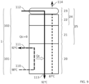
- the inlet 112 configured to bring the refrigerant-rich working solution into the second zone 102 and the outlet 113 configured to ensure the outlet of the refrigerant-lean working solution from the first zone 101 are arranged to ensure a downward circulation of the working solution through the second zone 102 then the first zone 101.
- the outlet 114 configured to ensure the outlet of the refrigerant vapor produced from the second zone 102) is arranged to ensure a circulation of the vapor produced upward through the first zone 101 then the second zone (102).
- the inlet 110 configured to bring a hot source into the first zone 101 and the outlet 111 configured to ensure the exit of the cooled hot source from the first zone 101 are arranged to ensure an upward circulation of the hot source through the first zone 101.
- the frame 100 is configured to form a single-block generator 1 integrating the desorber and the rectifier.
- the absorption machine comprises a working solution comprising the ammonia/water couple (NH 3 /H 2 O).
- the rectification device ensures the rectification of the refrigerant vapor advantageously by heat and mass exchange with the refrigerant-rich solution which then plays the role of heat transfer fluid cooling the refrigerant vapor to condense the absorbent vapors which are recovered by the refrigerant-rich solution.
- the rectification device ensures this rectification thanks to an optimized distribution of the refrigerant-rich working solution and an easier evacuation of the refrigerant vapor produced.
- Another aspect relates to a generator for an absorption machine comprising a desorber configured to receive a working solution comprising a refrigerant and an absorbent and intended for the production of refrigerant vapor characterized in that it comprises a rectification device as described above, the rectification device being arranged directly above the desorber.
- an absorption machine for producing cold comprising an absorber, a generator, a condenser, an evaporator and an absorption fluid circuit capable of receiving a working solution comprising a refrigerant and an absorbent, the fluid circuit connecting the generator to the condenser, the condenser to the evaporator (3), the evaporator to the absorber and the absorber to the generator, characterized in that it comprises a rectification device as described above.
- the distribution module includes a screen for collecting the refrigerant-rich working solution and a plurality of refrigerant vapor exhaust elements.
- the plurality of refrigerant vapor exhaust elements include chimneys provided on the collector screen.
- the chimneys are preferably configured so as not to collect the working solution rich in refrigerant.
- the plurality of exhaust elements are passage strips arranged on the collector screen configured to ensure the exhaust of the refrigerant vapor and arranged parallel to each other and preferably regularly defining screen strips separated by the passage strips.
- This arrangement allows the different flows of working solution fluid and gas vapor to circulate in an optimized manner.
- the distribution module includes a refrigerant-rich working solution reservoir including a frame and a bottom, the bottom being formed by the screen including the plurality of exhaust elements.
- the pre-distribution module comprises a plurality of pipes pierced with holes, also called flutes, and advantageously at least one pipe for supplying the working solution rich in refrigerant fluid into the plurality of flutes, configured to supply the distribution module.
- the flutes are arranged above the screen and between the exhaust chimneys of the refrigerant fluid vapor.
- the holes in the pipes allow the working solution to be sprayed in identical jets into the distribution module.
- the pipes with holes are arranged opposite the sieve strips.
- the pipes pierced with holes are not arranged above the exhaust elements, i.e. the chimneys, i.e. the passage strips for the refrigerant vapor rising from the rectifier.
- the rectifier comprises a plurality of plates advantageously called adiabatic, in particular in the case in which the rectifier is an adiabatic rectifier.
- the adiabatic plates participate in the uniform distribution of the working solution to the desorber and more particularly to the plates of the exchanger.
- the plates are advantageously arranged parallel to each other in a vertical direction, their longitudinal plane extending in a vertical direction.
- the rectifier is preferably a falling film exchanger.
- the plates are corrugated and preferably perforated, which optimizes the heat and mass exchanges between the working solution and the refrigerant vapor.
- the wetted surface in the context of falling film exchangers, in order to optimize the heat and mass exchanges between the plates, the wetted surface must be as large as possible. This is why a good distribution of the solution on the plates is essential.
- the adiabatic plates are arranged perpendicular to the plane of the sieve.
- the adiabatic plates are in contact with the sieve.
- the distribution module is configured to cooperate with the adiabatic plates, preferably the frame of the distribution module comprises notches intended to receive the adiabatic plates.
- the present invention relates to a generator 1 for the production of vapor of a refrigerant fluid.
- the generator 1 according to the invention is advantageously integrated into a thermodynamic system with an absorption cycle, that is to say an absorption machine.
- An absorption machine is a reversible heat pump with thermal "compression” using refrigerant/sorbent couples with strong affinities in order to replace the vapor compression of traditional machines.
- This solution has low electrical consumption, the main energy coming from the thermal source, making it possible to limit the operating cost in the case of the recovery of a low-cost energy source such as gas for example or free (such as solar energy or heat rejection for example).
- This type of absorption machine works thanks to the ability of certain liquids to absorb (exothermic reaction) and desorb (endothermic reaction) a vapor. They also use the fact that the solubility of this vapor in the liquid depends on the temperature and pressure. Thus, these machines use as a working solution a binary mixture, one of the components of which is more volatile than the other, and constitutes the refrigerant.
- An absorption machine is therefore composed of 4 main exchangers (generator, absorber, condenser and evaporator), and advantageously a cycle optimization exchange (economizer), a solution pump and two expansion valves.
- This type of absorption machine operates according to three temperature levels: a low temperature level corresponding to the production of cold at the evaporator, an intermediate temperature level corresponding to the condensation temperature of the refrigerant, but also to that of absorption of the refrigerant by the absorbent and a high temperature level corresponding to the driving temperature of the generator.
- thermodynamic cycle is feasible because of the vapor pressure difference between the absorbent and the refrigerant which is variable depending on the temperature and pressure. This variability allows for a concentration difference between the lean solution and the rich solution described below.
- the advantage of this absorption cycle is that mechanical compression is replaced by thermochemical compression which uses heat, i.e. a degraded primary energy source. The only primary energy input required is at the solution pump, but its work is approximately 96 times less than the work that the vapor compressor must provide for similar operating conditions.
- the absorption machine comprises a working solution: refrigerant, also called refrigerant, an absorbent.
- refrigerant also called refrigerant
- absorbent concentrations of the working solution and the absorbent in the working solution are adapted to the operating pressure and temperature of the absorption machine and lower than the crystallization concentration of the solution.
- a working solution using the ammonia/water pair (NH 3 /H 2 O) can be used.
- This NH 3 /H 2 O working solution pair makes it possible to produce negative cold, for example down to -30°C, for ambient temperatures up to 55°C.
- This pair has a low solidification temperature, whether that of ammonia or that of the ammonia/water mixture.
- This pair can therefore be used for air conditioning applications, but also for refrigeration and there is no possible crystallization over the pressure and temperature operating ranges.
- the vapor pressure difference between the absorbent and the refrigerant is small. This is why the absorption machine integrates a rectifier to rectify the ammonia vapor produced, i.e. to remove at least partially some of the traces of water carried with the ammonia vapor at the generator outlet.
- the working solution is said to be rich, because the refrigerant concentration is greater than in the so-called lean working solution.
- the Rich solution and lean solution refer to the refrigerant-rich working solution and the refrigerant-lean working solution respectively.
- fluid connections are preferably direct, that is to say without any other element unless this is specified.
- the absorption machine comprises: A generator 1 configured to vaporize the refrigerant.
- the generator is fluidically connected to the absorber 4 and to the condenser 2.
- the generator 1 comprises a fluid connection 14 with the absorber 4, possibly with an economizer, allowing the entry of the so-called rich working solution into the generator 1.
- the generator 1 comprises a fluid connection 15 with the absorber 4, possibly with an economizer, allowing the exit of the so-called lean working solution from the generator 1.
- a pressure reducer or expansion valve for the solution 7 is arranged on the fluid connection 15 allowing the pressure of the so-called lean working solution to be relaxed before it is transmitted to the absorber 4 by the fluid connection 15.
- the generator 1 comprises a fluid connection 11 with the condenser 2 allowing the exit of the refrigerant vapor from the generator 1.
- the generator 1 also comprises a hot source inlet 110 and outlet 111 allowing the heat supply necessary for vaporization. refrigerant.
- the rich solution from the absorber 4 is heated by a heat source that may be a high-temperature heat transfer fluid that passes through the desorber 20. Thanks to this heat, part of the refrigerant, in particular the ammonia contained in the rich solution, as well as traces of water, are desorbed.
- the depleted solution resulting from this process returns to the absorber 4.
- the desorption process takes place at high pressure, and requires a quantity of heat (Qg).
- the steam emitted by the desorber is conveyed to the rectifier integrated into the generator 1 according to the invention.
- the heat transfer fluid is chosen from pressurized water, glycol water, oil, water vapor or a gas.
- the absorption machine comprises: A condenser 2 configured to condense the refrigerant vapor.
- the condenser 2 is fluidically connected to the generator 1 and to the evaporator 3.
- the condenser 2 comprises a fluid connection 11 from the generator 1 allowing the refrigerant vapor to enter the condenser 2.
- the condenser 2 comprises a fluid connection 12 with the evaporator 3, more precisely with a refrigerant expansion valve or expansion valve 8, allowing the refrigerant to exit in the liquid state.
- the condenser 2 also comprises an external fluid inlet also called cold source and an outlet of the external fluid or heated cold source.
- the refrigerant vapor generated by the generator 1 is cooled by the ambient air or by an external fluid to condense and become liquid again.
- the liquid refrigerant advantageously passes through an expansion valve (or pressure reducer) 8 to reduce its pressure before entering the evaporator 3. Condensation requires high pressure and releases a quantity of heat (Qc).
- the unit comprises an expansion valve 8 arranged between the condenser 2 and the evaporator 3.
- the expansion valve 8 is configured to expand the refrigerant in the liquid state coming from the condenser 2.
- the expansion valve 8 brings the refrigerant to its evaporation pressure.
- the absorption machine comprises: An evaporator 3 configured to vaporize the refrigerant.
- the evaporator 3 is fluidically connected to the condenser 2 and to the absorber 4.
- the evaporator 3 comprises a fluid connection 12 from the condenser 2, more precisely with an expansion valve 8, allowing the refrigerant in the liquid state to enter the evaporator 3.
- the evaporator 3 comprises a fluid connection 13 with the absorber 4, allowing the refrigerant vapor to exit.
- the evaporator advantageously comprises an inlet and an outlet for a heat transfer fluid intended to be cooled by the evaporator.
- the refrigerant in an example almost pure ammonia
- the refrigerant in liquid phase enters evaporator 3, where a cold heat transfer fluid circulates.
- the refrigerant takes the heat from the cold source to evaporate, which induces the production of cold from the absorption machine (Qe).
- Qe absorption machine
- the pressure is low and a low temperature heat input is necessary to allow the evaporation of the refrigerant.
- the absorption machine comprises: An absorber 4 configured to condense the refrigerant vapor from the evaporator 3.
- the absorber 4 is fluidically connected to the evaporator 3 and to the generator 1.
- the absorber 4 comprises a fluid connection 13 from the evaporator 3 allowing the refrigerant in vapor state to enter the absorber 4.
- the absorber 4 comprises a fluid connection 14 with the generator 1, more precisely with a pump 6 intended to circulate the working solution in the fluid circulation circuit, more precisely a so-called rich working solution leaves the absorber 4 in the direction of the generator 1 via the fluid connection 14.
- the pump 6 is fluidically connected to an economizer through In absorber 4, the lean solution, advantageously composed of water and a small fraction of refrigerant, is pumped from generator 1 and distributed along absorber 4.
- the lean solution absorbs the refrigerant vapor that comes from evaporator 3 and becomes an enriched solution, close to its saturated condition.
- the rich solution goes to generator 1.
- the absorption process occurs at low pressure, releasing a quantity of heat (Qa) into the ambient air or into a cooling circuit.
- the generator 1 according to the invention integrates the functions of desorber 20 and rectifier 21 and advantageously of distribution.
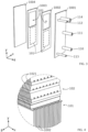
- the generator 1 comprises a frame 100 defining an interior volume.
- the interior volume advantageously comprises at least two distinct zones, a first zone 101 and a second zone 102.
- the first zone 101 and the second zone 102 are preferably arranged one above the other in a longitudinal direction extending along the largest dimension of the frame 100.
- the longitudinal direction of the frame 100 extends along the y axis.
- the first zone 101 and the second zone 102 are superimposed.
- the first zone 101 is arranged in the lower part of the frame 100 and the second zone 102 is arranged in the upper part of the frame 100.
- the lower part and the upper part of the frame 100 are understood to be relative to each other.
- the first zone 101 is configured to receive a desorber 20.
- the desorber 20 is intended to allow the production of refrigerant vapor.
- the desorber 20 comprises a plate exchanger.
- the plate exchanger comprises a plurality of plates 1002, 1003.
- the plate exchanger comprises a plurality of plates 1002 and a plurality of plates 1003 arranged to define circulation compartments respectively of the hot source and of the working solution with the refrigerant fluid vapor produced.
- the plates are thin metal plates which are separated and sealed by a set of rubber gaskets which provide the desirable distribution of the working solution and the hot source over the plurality of plates 1002, 1003.
- the plate 1002 has a first face configured to ensure the circulation of the hot source, and a second face configured to ensure the circulation of the working solution and the steam produced.
- the plate 1003 has a first face configured to ensure the circulation of the hot source, and a second face 10032 configured to ensure the circulation of the working solution and the steam produced.
- the first faces of the plates 1002 and 1003 are arranged facing to face to form a circulation compartment of the hot source and the second faces of the plates 1002 and 1003 are arranged face to face to form a circulation compartment of the working solution and the steam produced.
- the plate exchanger forming the desorber 20 according to the invention is a falling film plate exchanger.
- Falling film means a continuous flow of liquid along a surface with a continuous flow of gas, the two flows being separated by a liquid-vapor interface through which mass and heat transfers can take place.
- the liquid film is advantageously of low thickness of the order of 0.1 mm.
- this type of exchanger ensures a large exchange surface with the vapor circulating therein together.
- the second zone 102 is configured to receive a rectifier 21.
- the rectifier is intended to allow the purification of the refrigerant vapor produced in the first zone 101 at the desorber 20.
- the rectifier 21 makes it possible to eliminate at least part of the traces of the absorbent, in particular water, remaining in the vapor of the refrigerant fluid, in particular ammonia, at the outlet of the desorber 20.
- the rectification is carried out at high pressure and releases a quantity of heat (Qr).
- Qr quantity of heat
- the rectifier 21 comprises a plurality of adiabatic plates 1021.
- Adiabatic plates 1021 are understood to mean, for example, plates providing cooling of the steam produced to ensure separation of traces of the absorbent.
- the plates 1021 allow direct contact between the falling films of rich solution on the plates 1021 and the rising refrigerant vapor.
- the adiabatic plates 1021 are thin metal plates.
- the plates 1021 are corrugated to ensure a slowing down of the flow of refrigerant vapor rising into the second zone 102 from the first zone 101.
- the plates can also be straight, i.e. flat. This configuration also advantageously contributes to the distribution of the working solution in the second zone 102 to be distributed uniformly in the desorber 20 arranged in the first zone 101.
- the plates 1021 are pierced with through openings to ensure a mass exchange between the falling rich solution and the refrigerant vapor produced in the desorber 20 and rising.
- the circulation of the rich solution and the vapor is advantageously counter-current.
- the refrigerant vapor circulating between the plates 1021 in counter-current is rectified by partial reabsorption of the absorption vapor present in the sub-cooled rich solution.
- the rectifier 21 is integrated into a rectification device 25.
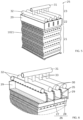
- the plates 1002, 1003 of the plate exchanger of the desorber 20 and the adiabatic plates 1021 of the rectifier 21 are superimposed.
- the plates 1002, 1003 of the plate exchanger of the desorber 20 and the adiabatic plates 1021 of the rectifier 21 are superimposed in their longitudinal direction.
- the plates 1002, 1003 of the desorber 20 and the plates of the rectifier 1021 are contiguous, that is to say that they are in direct contact, as illustrated in figure 4 .
- the plates 1002, 1003 of the desorber 20 are arranged in the first zone 101 in a vertical orientation.
- the plates 1002, 1003 of the desorber 20 are parallel to each other. It is understood that the plates are arranged so that their longitudinal direction, i.e. the greatest length, is arranged parallel to the vertical direction.
- a face of a plate of the desorber 20 defines a direction x included in the plane of the face and a direction y orthogonal to the direction x and also included in the plane of the face.
- the direction x being preferably parallel to the width of the plate
- the direction y being preferably parallel to the length of the plate.
- the thickness of the plate corresponds to the direction z, orthogonal to the plane of the face containing the directions x and y.
- the plates 1021 of the rectifier 21 are arranged in the second zone 102 in a vertical orientation.
- the plates 1021 of the rectifier are parallel to each other. It is understood that the plates are arranged so that their longitudinal direction, i.e. the greatest length, is arranged parallel to the vertical direction.
- the plates 1021 of the rectifier are arranged perpendicular to the plates 1002, 1003 of the desorber 20, as illustrated in figure 4 .
- the plates 1021 of the rectifier can be inclined or parallel to the plates 1002, 1003 of the desorber 20.
- the plates 1021 of the rectifier are arranged relative to the plates 1002, 1003 of the desorber 20 so that the longitudinal plane of the plate 1021 includes the directions y and z.
- the rectifier 21 comprises a cooling fluid circuit advantageously ensuring the circulation of the cooling fluid along the adiabatic plates 1021, more precisely certain adiabatic plates.
- the cooling fluid circuit makes it possible to improve the rectification.
- the frame 100 of the generator 1 is advantageously a frame of a plate exchanger.
- the frame 100 comprises a first bottom plate 1001 and a second bottom plate 1002.
- the first bottom plate 1001 and the second bottom plate 1002 are arranged parallel to the plates 1002, 1003 of the desorber 20, as illustrated in figure 3 .
- the frame 100 comprises an upper rail, resting on the first bottom plate 1001 and advantageously supports all of the plates 1002, 1003 of the desorber 20 and can allow their easy movement by sliding for assembly and possible cleaning.
- the frame 100 comprises a lower guide, placed in the lower part of the first bottom plate 1001 and holds the plates in position.
- the frame 100 comprises tie rods distributed around the perimeter of the frame, ensuring the tightening of the plates between the first bottom plate 1001 and the second bottom plate 1002. Hydraulic cylinders can be provided to perform the rapid tightening and loosening of the exchanger.
- the plates 1002 and 1003 of the desorber 20 are configured to comprise a first part and a second part.
- the first part of the plates 1002 and 1003 corresponds to the function of the desorber 20.
- the first part of the plates 1002 and 1003 each comprise, as described above, two first faces and two second faces configured to ensure the circulation of the hot source and, of the working solution and of the steam produced, respectively.
- the first part corresponds to the lower part of the plates 1002 and 1003.
- the second part of the plates 1002 and 1003 corresponds to the upper part of said plates.
- the second part is advantageously a hollow part, that is to say that in their second part, the plates 1002, 1003 advantageously comprise only a periphery defining an empty space.
- the second part of the plates 1002 and 1003 is intended to receive the rectifier 21 and more precisely the adiabatic plates 1021 of the rectifier.
- This configuration makes it possible to ensure a classic structure of a plate exchanger for generator 1 while integrating the rectifier function 21.
- the first bottom plate 1001 or the second bottom plate 1002 comprises the fluid connections configured to ensure the circulation of the different fluids.
- the first bottom plate 1001 comprises: part of the plates 1002 and 1003 is intended to receive the rectifier 21 and more precisely the adiabatic plates 1021 of the rectifier.
- This configuration makes it possible to ensure a classic structure of a plate exchanger for generator 1 while integrating the rectifier function 21.
- the first bottom plate 1001 or the second bottom plate 1002 comprises the fluid connections configured to ensure the circulation of the different fluids.
- the generator 1 is configured to ensure the circulation of the different fluids.
- the circulation of the fluids is carried out as described below:
- the generator 1 advantageously comprises a circulation of a heat source in the first zone 101 in an upward direction.
- the generator 1 advantageously comprises a circulation of working solution in the second zone 102 then in the first zone 101 in a downward direction counter to the heat source in the first zone 101.
- the working solution flows into the second zone 102 then into the first zone 101 by pressure and under the effect of gravity.
- the generator 1 advantageously comprises a circulation of refrigerant vapor, produced in the first zone 101, in the first zone 101 then in the second zone 102 in an upward direction counter-current to the working solution.
- the distribution of the rich working solution is done on the adiabatic plates 1021 of the rectifier.
- This distribution has a dual purpose: it allows both to standardize the flow of solution along the plates 1002, 1003 of the desorber 20 for a good distribution of the solution. And it also makes it possible to rectify the steam circulating there in counter-current by partial reabsorption of the absorbent vapor such as water present, by the enriched solution here sub-cooled.
- steam generation is achieved by the heat input from the hot source flowing from the bottom to the top of the desorber 20, counter-current to the working solution which flows by gravity.
- the working solution flows over the plates 1002, 1003, for example in a compartment defined by the second faces of the plates 1002 and 1003, while the hot source flows counter-currently from bottom to top, for example in a compartment defined by the first faces of the plates 1002 and 1003.
- the working solution and the hot source circulate in the form of a streaming film and allow a larger contact surface for heat exchanges between the hot source and the working solution and heat and mass exchanges with the steam generated along the film, counter-current.
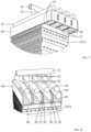
- the rectification device 25 advantageously comprises a distribution system 24.
- the distribution system 24 is configured to distribute the refrigerant-rich working solution into the rectifier 21.
- the distribution system 24 is advantageously arranged above the rectifier 21.
- the distribution system 24 is arranged at the upper end of the rectifier 21 and more particularly above the plates 1021, that is to say at the upper end of the plates 1021.
- the distribution system 24 advantageously comprises a distribution module 22.
- the distribution system 24 advantageously comprises a pre-distribution module 23.
- the distribution module 22 is configured to ensure the distribution and distribution of the refrigerant-rich working solution in the rectifier 21.
- the distribution module 22 is also configured to allow the escape of the rectified refrigerant vapor produced in the rectifier 21.
- the distribution module 22 comprises a collector screen 26 intended to receive the working solution rich in refrigerant fluid and a plurality of exhaust elements for the rectified refrigerant fluid vapor.
- the collector screen 26 also called a retention tank comprising a distribution bottom is configured to receive, and advantageously store, temporarily the working solution rich in refrigerant fluid to allow homogeneous distribution to the rectifier 21.
- the collecting sieve 26 advantageously has the function of a reservoir or retention tank, into which the rich solution is poured, preferably after its passage through the predistribution module.
- the tank comprises, for example, a frame 29.
- the bottom of the retention tank is composed of a sieve 26, designed first to let the solution spread over the entire surface, then to let it pass through the perforations, and thus flow below, advantageously along the adiabatic plates 1021 of the rectifier 21.
- the sieve 26 may be a porous plate or a perforated plate.
- the perforations are distributed randomly, depending on the structure envisaged: porous structure, bed of beads, perforated wall, etc.
- the sieve is configured to allow the solution to pass through multiple locations.
- the distribution module 22 is in contact with the plates 1021 of the rectifier 21, more specifically, the sieve 26 is in direct contact with the adiabatic plates 1021 where the falling film of rich solution is formed.
- the frame 29 and the plates 1021 are configured to cooperate.
- the frame 29 comprises notches 34 regularly distributed on at least two parallel sides of the frame 29 and configured to receive the upper part of the plates 1021.
- the upper part of the plates 1021 comprises for example a notch or another means configured to cooperate with a notch 34 and in particular making it possible to ensure a blocking in horizontal translation of the plate 1021 in the notch 34.
- the distribution module 22 advantageously comprises elements for exhausting steam from the lower parts of the rectification device and in particular from the rectifier 21.
- the exhaust elements define passage bands 27 arranged on the sieve 26 ensuring the passage of the steam rising from the rectifier 21.
- the passage bands 27 are configured to ensure the passage of the steam while limiting modifications in the flow of the rich solution through the sieve 26 and advantageously on the plates 1021.
- the steam exhaust elements comprise chimneys 30 arranged on the collector screen 26.
- the chimneys 30 comprise, for example, two walls 35 parallel to each other arranged perpendicular to the plane of the screen 26. Two walls 35 facing each other define a passage strip 27.
- the walls 35 are advantageously solid.
- the chimneys 30 are advantageously not supplied with rich solution.
- the chimneys 30 are preferably spaced regularly, preferably defining passage strips 27 parallel to each other.
- the passage strips 27 are preferably arranged perpendicular to the plane of the plates 1021 of the rectifier 21.
- two chimneys 30 define sieve bands 28 which are supplied with rich solution.
- the sieve strips 28 are wider than the passage strips 27.
- a ratio of 1 to 5 or even 1 to 10 can be provided.
- the passage strips 27 are configured so as not to disturb the flow of liquid on the plates advantageously arranged under the sieve.
- the passage strips 27 defined in particular by chimneys 30 are arranged in the sieve 26. They thus create junction zones between the plates 1021 and the distribution module 24 which are not supplied by the rich solution. Indeed, this gives regularly spaced paths at the top of each plate 1021 so that the steam can escape. This prevents it from grouping together in a single place, if there was only one outlet for example.
- the width of the passage strips 27 being small relative to the width of the sieve strips 28, this will have little impact on the flow of the solution on the plates 1021.
- the steam evacuation surface is thus larger and better distributed over the entire sieve 26.
- the distribution system 24 advantageously comprises a pre-distribution module 23.
- the pre-distribution module 23 is preferably arranged above the distribution module 22.
- the pre-distribution module 22 is configured to distribute and distribute the rich solution in the distribution module 22.
- the predistribution module 23 is intended to ensure the supply of rich solution to the distribution module and preferentially the supply of the sieve belts 28 and the non-supply 27 of the passage belts 27.
- the predistribution module 23 comprises a plurality of pipes 32 preferably arranged above the sieve strips 28 to ensure the supply of rich solution to the sieve 26.
- the pipes 32 are arranged such that the longitudinal axis of each pipe 32 extends parallel to the plane of the screen 26.
- the screen 26 and the pipes 32 extend in a horizontal direction.
- the pipes 32 comprise, for example, a plurality of perforations preferentially facing the sieve 26.
- the pipes 32 are also called flutes.
- the rich solution will flow through these flutes.
- the perforations of the pipes 32 are advantageously uniformly arranged in the form of small holes allowing a homogeneous distribution of the flow of rich solution.
- the placement of these small holes all along the pipes 32 makes it possible to cause the solution to spurt by identical jets into the sieve tank, more precisely into the sieve strips 28, and therefore not to cause a greater flow at one location, and to impact the flow of the solution through the sieve 26.
- the pipes 32 are parallel to each other and arranged with respect to the sieve strips 28.
- the pipes 32 are preferably supplied by at least one supply pipe 31 of the rich working solution.
- the supply pipe 31 is fluidically connected to the pipes 32 for example by junction pipes 33.
- the invention finds its application for the production of cold from medium and low temperature heat sources, for example between 30°C and 100°C such as thermal discharges from industrial processes, solar thermal, biomass, geothermal energy, gas turbines, heat networks;
- the implementation of the invention can be done in the field of transport on gasoline, diesel and gas turbine engines, or for maritime transport;
- the absorption machine can be implemented in a heat pump.
- the manufacturing materials of the rectification device 25 and more broadly of the generator 1 must be compatible with liquid ammonia and gaseous ammonia at temperatures of up to -110°C:
- Polymers such as PEEK or PEKK for example manufactured by 3D printing of parts by fusion or even in Metal: mainly STAINLESS STEEL, with the possibility of printing by layers or cutting of parts by laser, combined with machining and welding.
- Such an absorption machine makes it possible to obtain an ammonia vapor purity of less than 0.98 in mass fraction.
Landscapes
- Engineering & Computer Science (AREA)
- Mechanical Engineering (AREA)
- General Engineering & Computer Science (AREA)
- Physics & Mathematics (AREA)
- Thermal Sciences (AREA)
- Power Engineering (AREA)
- Sorption Type Refrigeration Machines (AREA)
Claims (9)
- Generator (1) für Absorptionsmaschine, der ein Gestell (100) umfasst, das einen Innenraum definiert, der eine erste Zone (101) umfasst, die einen Desorber umfasst, der dazu konfiguriert ist, eine Arbeitslösung aufzunehmen, die ein Kältemittel und ein Absorptionsmittel umfasst und zur Erzeugung von Kältemitteldampf bestimmt ist, dadurch gekennzeichnet, dass der Desorber einen Fallfilm-Plattenwärmetauscher umfasst, und dass das Gestell (100) eine zweite Zone (102) umfasst, die über der ersten Zone (101) eingerichtet ist, die einen adiabatischen Rektifikator umfasst, der eine Vielzahl adiabatischer Platten (1021) umfasst und zur Eliminierung von Absorptionsmitteldampfspur aus dem Kältemitteldampf, der in der ersten Zone (101) erzeugt wird, bestimmt ist, wobei der Desorber und der Rektifikator fluidisch durch Überlagerung der Vielzahl adiabatischer Platten (1021) und Fallfilm-Platten (1002, 1003) verbunden sind, wobei die adiabatischen Platten (1021) und die Fallfilm-Platten (1002, 1003) zueinander derart eingerichtet sind, dass sich die Fallfilm-Platten (1002, 1003) in einer Ebene erstrecken, die die x- und die y-Richtung enthält, und sich die adiabatisches Platten in einer Ebene erstrecken, die die y- und die z- Richtung enthält.
- Generator nach dem vorstehenden Anspruch, wobei das Gestell (100) Folgendes umfasst:- mindestens einen Eingang (112), der dazu konfiguriert ist, die kältemittelreiche Arbeitslösung in die zweite Zone (102) zu bringen,- mindestens einen Ausgang (113), der dazu konfiguriert ist, den Ausgang der kältemittelarmen Arbeitslösung aus der ersten Zone (101) sicherzustellen,- mindestens einen Ausgang (112), der dazu konfiguriert ist, den Ausgang des Kältemitteldampfs, der in der zweiten Zone (102) erzeugt wird, sicherzustellen,- mindestens einen Eingang (110), der dazu konfiguriert ist, eine Wärmequelle in die erste Zone (101) zu bringen,- mindestens einen Ausgang (111), der dazu konfiguriert ist, den Ausgang der abgekühlten Wärmequelle aus der ersten Zone (101) sicherzustellen.
- Generator nach dem vorstehenden Anspruch, wobei der Eingang (112), der dazu konfiguriert ist, die kältemittelreiche Arbeitslösung in die zweite Zone (102) zu bringen, und der Ausgang (113), der dazu konfiguriert ist, den Ausgang der kältemittelarmen Arbeitslösung aus der ersten Zone (101) sicherzustellen, dazu eingerichtet sind, eine absteigende Zirkulation der Arbeitslösung durch die zweite Zone (102) und dann die erste Zone (101) sicherzustellen.
- Generator nach einem der beiden vorstehenden Ansprüche, wobei der Ausgang (114), der dazu konfiguriert ist, den Ausgang des erzeugten Kältemitteldampfs aus der zweiten Zone (102) sicherzustellen, dazu eingerichtet ist, eine aufsteigende Zirkulation des erzeugten Dampfs durch die erste Zone (101) und dann durch die zweite Zone (102) sicherzustellen.
- Generator nach einem der drei vorstehenden Ansprüche, wobei der Eingang (110), der dazu konfiguriert ist, eine Wärmequelle in die erste Zone (101) zu bringen, und der Ausgang (111), der dazu konfiguriert ist, den Ausgang der abgekühlten Wärmequelle aus der ersten Zone (101) sicherzustellen, dazu eingerichtet sind, eine aufsteigende Zirkulation der Wärmequelle durch die erste Zone (101) sicherzustellen.
- Generator nach einem der vorstehenden Ansprüche, wobei das Gestell (100) dazu konfiguriert ist, einen einteiligen Generator (1) zu bilden, der den Desorber und den Rektifikator integriert.
- Absorptionsmaschine zur Kälteerzeugung, die einen Absorber (4), einen Generator (1), einen Kondensator (2), einen Verdampfer (3) und einen Absorptionsfluidkreislauf umfasst, der dazu geeignet ist, eine Arbeitslösung aufzunehmen, die ein Kältemittel und ein Absorptionsmittel umfasst, wobei der Fluidkreislauf den Generator (1) mit dem Kondensator (2), den Kondensator (2) mit dem Verdampfer (3), den Verdampfer (3) mit dem Absorber (4) und den Absorber (4) mit dem Generator (1) verbindet, dadurch gekennzeichnet, dass der Generator (1) ein Generator (1) nach einem der vorstehenden Ansprüche ist.
- Absorptionsmaschine nach dem vorstehenden Anspruch, die eine Arbeitslösung umfasst, die das Paar Ammoniak/Wasser (NH3/H2O) umfasst.
- Kältemitteldampf-Erzeugungsverfahren durch einen Generator (1) nach einem der Ansprüche 1 bis 6, dadurch gekennzeichnet, dass er Folgendes umfasst- die Zirkulation einer Wärmequelle in der ersten Zone (101) entlang einer aufsteigenden Richtung, und- eine Arbeitslösungszirkulation in der zweiten Zone (102) und dann in der ersten Zone (101) entlang einer absteigenden Richtung im Gegenstrom zu der Wärmequelle der ersten Zone (101), und- eine Zirkulation des Kältemitteldampfs, der in der ersten Zone (101) erzeugt wird, in der ersten Zone (101) und dann in der zweiten Zone (102) entlang einer aufsteigenden Richtung im Gegenstrom zu der Arbeitslösung.
Applications Claiming Priority (1)
| Application Number | Priority Date | Filing Date | Title |
|---|---|---|---|
| FR2002911A FR3108711B1 (fr) | 2020-03-25 | 2020-03-25 | Générateur comprenant une fonction de rectification et machine à absorption comprenant ledit générateur |
Publications (2)
| Publication Number | Publication Date |
|---|---|
| EP3885672A1 EP3885672A1 (de) | 2021-09-29 |
| EP3885672B1 true EP3885672B1 (de) | 2024-11-27 |
Family
ID=70295554
Family Applications (1)
| Application Number | Title | Priority Date | Filing Date |
|---|---|---|---|
| EP21164702.9A Active EP3885672B1 (de) | 2020-03-25 | 2021-03-24 | Generator mit einer rektifikationsfunktion, une absorptionsmaschine, die diesen generator umfasst, und ein verfahren zur erzeugung von kältemitteldampf durch den generator |
Country Status (2)
| Country | Link |
|---|---|
| EP (1) | EP3885672B1 (de) |
| FR (1) | FR3108711B1 (de) |
Families Citing this family (1)
| Publication number | Priority date | Publication date | Assignee | Title |
|---|---|---|---|---|
| FR3135316B1 (fr) | 2022-05-06 | 2024-05-03 | Commissariat Energie Atomique | Procede de traitement de surface pour ameliorer la performance d’un systeme thermodynamique avec cycle a absorption |
Family Cites Families (4)
| Publication number | Priority date | Publication date | Assignee | Title |
|---|---|---|---|---|
| US5570584A (en) * | 1991-11-18 | 1996-11-05 | Phillips Engineering Co. | Generator-Absorber heat exchange transfer apparatus and method using an intermediate liquor |
| US5660049A (en) * | 1995-11-13 | 1997-08-26 | Erickson; Donald C. | Sorber with multiple cocurrent pressure equalized upflows |
| CN103983046B (zh) * | 2014-06-09 | 2016-04-20 | 泰山集团股份有限公司 | 宽窄通道板式满液发生器和降膜吸收器及氨水吸收制冷机 |
| FR3082608B1 (fr) * | 2018-06-19 | 2020-11-20 | Commissariat Energie Atomique | Systeme comprenant une machine a absorption pour la production de froid a partir de la chaleur fatale de gaz d'echappement d'un vehicule comprenant un module de stockage de l'energie thermique |
-
2020
- 2020-03-25 FR FR2002911A patent/FR3108711B1/fr active Active
-
2021
- 2021-03-24 EP EP21164702.9A patent/EP3885672B1/de active Active
Also Published As
| Publication number | Publication date |
|---|---|
| FR3108711A1 (fr) | 2021-10-01 |
| FR3108711B1 (fr) | 2022-06-17 |
| EP3885672A1 (de) | 2021-09-29 |
Similar Documents
| Publication | Publication Date | Title |
|---|---|---|
| FR2593588A1 (fr) | Machine frigorifique a adsorption | |
| EP3885672B1 (de) | Generator mit einer rektifikationsfunktion, une absorptionsmaschine, die diesen generator umfasst, und ein verfahren zur erzeugung von kältemitteldampf durch den generator | |
| EP0148756A2 (de) | System zum Aufwertem thermischer Energie mit niedrigem Niveau unter Ausnutzung der Verdampfung, und Mischung zweier strömender Medien mit gleichem Dampfdruck bei unterschiedlichen Temperaturen | |
| EP3885673A1 (de) | Rektifikationsvorrichtung, die eine rektifikationseinrichtung und eine verteilungsvorrichtung umfasst, und absorptionsmaschine, die diese rektifikationsvorrichtung umfasst | |
| EP3667201A1 (de) | Kälteerzeugungssystem, das mit einer kompressionsmaschine, einer absorptionsmaschine und einem thermischen speichersystem zur verbindung der beiden ausgestattet ist | |
| EP3584518B1 (de) | System, das eine absorptionsmaschine für die kälteerzeugung aus der abwärme vom abgas eines fahrzeugs und ein wärmeenergie-speichermodul umfasst, und ein verfahren und eine verwendung eines solchen systems | |
| FR3086040A1 (fr) | Systeme de climatisation comprenant une machine a absorption et une machine a compression mecanique | |
| EP3502577B1 (de) | Luftaufbereitungssystem, das eine vorrichtung zur absorption umfasst, und entsprechendes verfahren | |
| EP4092356B1 (de) | Absorptionsmaschine mit spiralförmigen plattenwärmetauschern | |
| EP4332463A1 (de) | Wärmeerzeugungsvorrichtung | |
| FR2468085A1 (fr) | Appareil frigorifique a sorption, procede pour la mise en service de cet appareil et utilisation de ce dernier | |
| EP3748274A1 (de) | System zur gleichzeitigen erzeugung von elektrischer energie und kalter und heisser wärmeenergie, und entsprechendes verfahren | |
| FR3140399A1 (fr) | Système de production d’énergie par cycle de Rankine organique et cycle à absorption intégrés | |
| EP3246651B1 (de) | Wärmetauscher mit mindestens drei fluiden mit verbesserter effizienz | |
| FR3097038A1 (fr) | Système de co-production d’énergie électrique et d’énergie thermique froide et procédé associé | |
| EP1751477A1 (de) | Wärmetauscher und wärmeübertragungsvorrichtung, im besonderen für ein kraftfahrzeug | |
| EP3584517A1 (de) | System, das eine absorptionsmaschine für die kälteerzeugung aus der abwärme vom abgas eines fahrzeugs und ein wärmeenergie-speichermodul umfasst | |
| FR3152177A1 (fr) | Transformateur de chaleur à absorption couplé à une machine frigorifique à absorption | |
| FR3110964A1 (fr) | Système de Stockage Thermique par MCP par contact direct d'un solvant | |
| FR3152176A1 (fr) | Transformateur de chaleur à absorption optimisé par éjecteur | |
| FR3114381A1 (fr) | Échangeur de sorption | |
| WO2017071959A1 (fr) | Dispositif de stockage d'énergie thermique par matériau à changement de phase solide/liquide comprenant un condenseur | |
| JP5124884B2 (ja) | 中温熱溶解式冷凍熱機関蒸発濃縮装置 | |
| FR3029611A1 (fr) | Systeme de liquefaction de gaz a machine a absorption et pompe a chaleur stirling | |
| EP2992278B1 (de) | Gleichrichter für thermodynamische absorptionsmaschine mit verbindungsvorrichtung als siphon |
Legal Events
| Date | Code | Title | Description |
|---|---|---|---|
| PUAI | Public reference made under article 153(3) epc to a published international application that has entered the european phase |
Free format text: ORIGINAL CODE: 0009012 |
|
| STAA | Information on the status of an ep patent application or granted ep patent |
Free format text: STATUS: REQUEST FOR EXAMINATION WAS MADE |
|
| 17P | Request for examination filed |
Effective date: 20210324 |
|
| AK | Designated contracting states |
Kind code of ref document: A1 Designated state(s): AL AT BE BG CH CY CZ DE DK EE ES FI FR GB GR HR HU IE IS IT LI LT LU LV MC MK MT NL NO PL PT RO RS SE SI SK SM TR |
|
| STAA | Information on the status of an ep patent application or granted ep patent |
Free format text: STATUS: EXAMINATION IS IN PROGRESS |
|
| 17Q | First examination report despatched |
Effective date: 20231206 |
|
| GRAP | Despatch of communication of intention to grant a patent |
Free format text: ORIGINAL CODE: EPIDOSNIGR1 |
|
| STAA | Information on the status of an ep patent application or granted ep patent |
Free format text: STATUS: GRANT OF PATENT IS INTENDED |
|
| INTG | Intention to grant announced |
Effective date: 20240625 |
|
| RIN1 | Information on inventor provided before grant (corrected) |
Inventor name: STUTZ, BENOIT Inventor name: PHAN, HAI TRIEU Inventor name: BOUDEHENN, FRANCOIS Inventor name: WIRTZ, MATHILDE |
|
| GRAS | Grant fee paid |
Free format text: ORIGINAL CODE: EPIDOSNIGR3 |
|
| GRAA | (expected) grant |
Free format text: ORIGINAL CODE: 0009210 |
|
| STAA | Information on the status of an ep patent application or granted ep patent |
Free format text: STATUS: THE PATENT HAS BEEN GRANTED |
|
| RAP3 | Party data changed (applicant data changed or rights of an application transferred) |
Owner name: UNIVERSITE SAVOIE MONT BLANC Owner name: CENTRE NATIONAL DE LA RECHERCHE SCIENTIFIQUE Owner name: COMMISSARIAT A L'ENERGIE ATOMIQUE ET AUX ENERGIESALTERNATIVES |
|
| AK | Designated contracting states |
Kind code of ref document: B1 Designated state(s): AL AT BE BG CH CY CZ DE DK EE ES FI FR GB GR HR HU IE IS IT LI LT LU LV MC MK MT NL NO PL PT RO RS SE SI SK SM TR |
|
| REG | Reference to a national code |
Ref country code: GB Ref legal event code: FG4D Free format text: NOT ENGLISH |
|
| REG | Reference to a national code |
Ref country code: CH Ref legal event code: EP |
|
| REG | Reference to a national code |
Ref country code: IE Ref legal event code: FG4D Free format text: LANGUAGE OF EP DOCUMENT: FRENCH |
|
| REG | Reference to a national code |
Ref country code: DE Ref legal event code: R096 Ref document number: 602021022278 Country of ref document: DE |
|
| REG | Reference to a national code |
Ref country code: SE Ref legal event code: TRGR |
|
| REG | Reference to a national code |
Ref country code: LT Ref legal event code: MG9D |
|
| REG | Reference to a national code |
Ref country code: NL Ref legal event code: MP Effective date: 20241127 |
|
| PGFP | Annual fee paid to national office [announced via postgrant information from national office to epo] |
Ref country code: SE Payment date: 20250327 Year of fee payment: 5 |
|
| PG25 | Lapsed in a contracting state [announced via postgrant information from national office to epo] |
Ref country code: IS Free format text: LAPSE BECAUSE OF FAILURE TO SUBMIT A TRANSLATION OF THE DESCRIPTION OR TO PAY THE FEE WITHIN THE PRESCRIBED TIME-LIMIT Effective date: 20250327 Ref country code: PT Free format text: LAPSE BECAUSE OF FAILURE TO SUBMIT A TRANSLATION OF THE DESCRIPTION OR TO PAY THE FEE WITHIN THE PRESCRIBED TIME-LIMIT Effective date: 20250327 Ref country code: HR Free format text: LAPSE BECAUSE OF FAILURE TO SUBMIT A TRANSLATION OF THE DESCRIPTION OR TO PAY THE FEE WITHIN THE PRESCRIBED TIME-LIMIT Effective date: 20241127 |
|
| PGFP | Annual fee paid to national office [announced via postgrant information from national office to epo] |
Ref country code: DE Payment date: 20250326 Year of fee payment: 5 |
|
| PG25 | Lapsed in a contracting state [announced via postgrant information from national office to epo] |
Ref country code: FI Free format text: LAPSE BECAUSE OF FAILURE TO SUBMIT A TRANSLATION OF THE DESCRIPTION OR TO PAY THE FEE WITHIN THE PRESCRIBED TIME-LIMIT Effective date: 20241127 Ref country code: NL Free format text: LAPSE BECAUSE OF FAILURE TO SUBMIT A TRANSLATION OF THE DESCRIPTION OR TO PAY THE FEE WITHIN THE PRESCRIBED TIME-LIMIT Effective date: 20241127 |
|
| REG | Reference to a national code |
Ref country code: AT Ref legal event code: MK05 Ref document number: 1746049 Country of ref document: AT Kind code of ref document: T Effective date: 20241127 |
|
| PG25 | Lapsed in a contracting state [announced via postgrant information from national office to epo] |
Ref country code: BG Free format text: LAPSE BECAUSE OF FAILURE TO SUBMIT A TRANSLATION OF THE DESCRIPTION OR TO PAY THE FEE WITHIN THE PRESCRIBED TIME-LIMIT Effective date: 20241127 |
|
| PG25 | Lapsed in a contracting state [announced via postgrant information from national office to epo] |
Ref country code: ES Free format text: LAPSE BECAUSE OF FAILURE TO SUBMIT A TRANSLATION OF THE DESCRIPTION OR TO PAY THE FEE WITHIN THE PRESCRIBED TIME-LIMIT Effective date: 20241127 |
|
| PG25 | Lapsed in a contracting state [announced via postgrant information from national office to epo] |
Ref country code: NO Free format text: LAPSE BECAUSE OF FAILURE TO SUBMIT A TRANSLATION OF THE DESCRIPTION OR TO PAY THE FEE WITHIN THE PRESCRIBED TIME-LIMIT Effective date: 20250227 |
|
| PG25 | Lapsed in a contracting state [announced via postgrant information from national office to epo] |
Ref country code: LV Free format text: LAPSE BECAUSE OF FAILURE TO SUBMIT A TRANSLATION OF THE DESCRIPTION OR TO PAY THE FEE WITHIN THE PRESCRIBED TIME-LIMIT Effective date: 20241127 Ref country code: GR Free format text: LAPSE BECAUSE OF FAILURE TO SUBMIT A TRANSLATION OF THE DESCRIPTION OR TO PAY THE FEE WITHIN THE PRESCRIBED TIME-LIMIT Effective date: 20250228 Ref country code: AT Free format text: LAPSE BECAUSE OF FAILURE TO SUBMIT A TRANSLATION OF THE DESCRIPTION OR TO PAY THE FEE WITHIN THE PRESCRIBED TIME-LIMIT Effective date: 20241127 |
|
| PG25 | Lapsed in a contracting state [announced via postgrant information from national office to epo] |
Ref country code: PL Free format text: LAPSE BECAUSE OF FAILURE TO SUBMIT A TRANSLATION OF THE DESCRIPTION OR TO PAY THE FEE WITHIN THE PRESCRIBED TIME-LIMIT Effective date: 20241127 |
|
| PGFP | Annual fee paid to national office [announced via postgrant information from national office to epo] |
Ref country code: FR Payment date: 20250327 Year of fee payment: 5 |
|
| PG25 | Lapsed in a contracting state [announced via postgrant information from national office to epo] |
Ref country code: RS Free format text: LAPSE BECAUSE OF FAILURE TO SUBMIT A TRANSLATION OF THE DESCRIPTION OR TO PAY THE FEE WITHIN THE PRESCRIBED TIME-LIMIT Effective date: 20250227 |
|
| PG25 | Lapsed in a contracting state [announced via postgrant information from national office to epo] |
Ref country code: SM Free format text: LAPSE BECAUSE OF FAILURE TO SUBMIT A TRANSLATION OF THE DESCRIPTION OR TO PAY THE FEE WITHIN THE PRESCRIBED TIME-LIMIT Effective date: 20241127 |
|
| PG25 | Lapsed in a contracting state [announced via postgrant information from national office to epo] |
Ref country code: DK Free format text: LAPSE BECAUSE OF FAILURE TO SUBMIT A TRANSLATION OF THE DESCRIPTION OR TO PAY THE FEE WITHIN THE PRESCRIBED TIME-LIMIT Effective date: 20241127 |
|
| PGFP | Annual fee paid to national office [announced via postgrant information from national office to epo] |
Ref country code: GB Payment date: 20250423 Year of fee payment: 5 |
|
| PG25 | Lapsed in a contracting state [announced via postgrant information from national office to epo] |
Ref country code: EE Free format text: LAPSE BECAUSE OF FAILURE TO SUBMIT A TRANSLATION OF THE DESCRIPTION OR TO PAY THE FEE WITHIN THE PRESCRIBED TIME-LIMIT Effective date: 20241127 |
|
| PG25 | Lapsed in a contracting state [announced via postgrant information from national office to epo] |
Ref country code: RO Free format text: LAPSE BECAUSE OF FAILURE TO SUBMIT A TRANSLATION OF THE DESCRIPTION OR TO PAY THE FEE WITHIN THE PRESCRIBED TIME-LIMIT Effective date: 20241127 |
|
| PG25 | Lapsed in a contracting state [announced via postgrant information from national office to epo] |
Ref country code: SK Free format text: LAPSE BECAUSE OF FAILURE TO SUBMIT A TRANSLATION OF THE DESCRIPTION OR TO PAY THE FEE WITHIN THE PRESCRIBED TIME-LIMIT Effective date: 20241127 |
|
| PG25 | Lapsed in a contracting state [announced via postgrant information from national office to epo] |
Ref country code: CZ Free format text: LAPSE BECAUSE OF FAILURE TO SUBMIT A TRANSLATION OF THE DESCRIPTION OR TO PAY THE FEE WITHIN THE PRESCRIBED TIME-LIMIT Effective date: 20241127 |
|
| PG25 | Lapsed in a contracting state [announced via postgrant information from national office to epo] |
Ref country code: IT Free format text: LAPSE BECAUSE OF FAILURE TO SUBMIT A TRANSLATION OF THE DESCRIPTION OR TO PAY THE FEE WITHIN THE PRESCRIBED TIME-LIMIT Effective date: 20241127 |
|
| REG | Reference to a national code |
Ref country code: DE Ref legal event code: R097 Ref document number: 602021022278 Country of ref document: DE |
|
| PLBE | No opposition filed within time limit |
Free format text: ORIGINAL CODE: 0009261 |
|
| STAA | Information on the status of an ep patent application or granted ep patent |
Free format text: STATUS: NO OPPOSITION FILED WITHIN TIME LIMIT |
|
| REG | Reference to a national code |
Ref country code: CH Ref legal event code: L10 Free format text: ST27 STATUS EVENT CODE: U-0-0-L10-L00 (AS PROVIDED BY THE NATIONAL OFFICE) Effective date: 20251008 |
|
| PG25 | Lapsed in a contracting state [announced via postgrant information from national office to epo] |
Ref country code: MC Free format text: LAPSE BECAUSE OF FAILURE TO SUBMIT A TRANSLATION OF THE DESCRIPTION OR TO PAY THE FEE WITHIN THE PRESCRIBED TIME-LIMIT Effective date: 20241127 |
|
| REG | Reference to a national code |
Ref country code: CH Ref legal event code: H13 Free format text: ST27 STATUS EVENT CODE: U-0-0-H10-H13 (AS PROVIDED BY THE NATIONAL OFFICE) Effective date: 20251023 |
|
| 26N | No opposition filed |
Effective date: 20250828 |
|
| PG25 | Lapsed in a contracting state [announced via postgrant information from national office to epo] |
Ref country code: LU Free format text: LAPSE BECAUSE OF NON-PAYMENT OF DUE FEES Effective date: 20250324 |
|
| REG | Reference to a national code |
Ref country code: BE Ref legal event code: MM Effective date: 20250331 |
|
| PG25 | Lapsed in a contracting state [announced via postgrant information from national office to epo] |
Ref country code: BE Free format text: LAPSE BECAUSE OF NON-PAYMENT OF DUE FEES Effective date: 20250331 |
|
| PG25 | Lapsed in a contracting state [announced via postgrant information from national office to epo] |
Ref country code: CH Free format text: LAPSE BECAUSE OF NON-PAYMENT OF DUE FEES Effective date: 20250331 |
|
| PG25 | Lapsed in a contracting state [announced via postgrant information from national office to epo] |
Ref country code: IE Free format text: LAPSE BECAUSE OF NON-PAYMENT OF DUE FEES Effective date: 20250324 |