EP3885587A1 - Adjustable hydrant strap - Google Patents
Adjustable hydrant strap Download PDFInfo
- Publication number
- EP3885587A1 EP3885587A1 EP21168025.1A EP21168025A EP3885587A1 EP 3885587 A1 EP3885587 A1 EP 3885587A1 EP 21168025 A EP21168025 A EP 21168025A EP 3885587 A1 EP3885587 A1 EP 3885587A1
- Authority
- EP
- European Patent Office
- Prior art keywords
- strap
- mounting
- housing
- monitoring device
- tab
- Prior art date
- Legal status (The legal status is an assumption and is not a legal conclusion. Google has not performed a legal analysis and makes no representation as to the accuracy of the status listed.)
- Granted
Links
Images





Classifications
-
- G—PHYSICS
- G01—MEASURING; TESTING
- G01M—TESTING STATIC OR DYNAMIC BALANCE OF MACHINES OR STRUCTURES; TESTING OF STRUCTURES OR APPARATUS, NOT OTHERWISE PROVIDED FOR
- G01M3/00—Investigating fluid-tightness of structures
- G01M3/02—Investigating fluid-tightness of structures by using fluid or vacuum
- G01M3/04—Investigating fluid-tightness of structures by using fluid or vacuum by detecting the presence of fluid at the leakage point
- G01M3/24—Investigating fluid-tightness of structures by using fluid or vacuum by detecting the presence of fluid at the leakage point using infrasonic, sonic or ultrasonic vibrations
- G01M3/243—Investigating fluid-tightness of structures by using fluid or vacuum by detecting the presence of fluid at the leakage point using infrasonic, sonic or ultrasonic vibrations for pipes
-
- F—MECHANICAL ENGINEERING; LIGHTING; HEATING; WEAPONS; BLASTING
- F16—ENGINEERING ELEMENTS AND UNITS; GENERAL MEASURES FOR PRODUCING AND MAINTAINING EFFECTIVE FUNCTIONING OF MACHINES OR INSTALLATIONS; THERMAL INSULATION IN GENERAL
- F16B—DEVICES FOR FASTENING OR SECURING CONSTRUCTIONAL ELEMENTS OR MACHINE PARTS TOGETHER, e.g. NAILS, BOLTS, CIRCLIPS, CLAMPS, CLIPS OR WEDGES; JOINTS OR JOINTING
- F16B1/00—Devices for securing together, or preventing relative movement between, constructional elements or machine parts
-
- F—MECHANICAL ENGINEERING; LIGHTING; HEATING; WEAPONS; BLASTING
- F16—ENGINEERING ELEMENTS AND UNITS; GENERAL MEASURES FOR PRODUCING AND MAINTAINING EFFECTIVE FUNCTIONING OF MACHINES OR INSTALLATIONS; THERMAL INSULATION IN GENERAL
- F16B—DEVICES FOR FASTENING OR SECURING CONSTRUCTIONAL ELEMENTS OR MACHINE PARTS TOGETHER, e.g. NAILS, BOLTS, CIRCLIPS, CLAMPS, CLIPS OR WEDGES; JOINTS OR JOINTING
- F16B2/00—Friction-grip releasable fastenings
- F16B2/02—Clamps, i.e. with gripping action effected by positive means other than the inherent resistance to deformation of the material of the fastening
- F16B2/06—Clamps, i.e. with gripping action effected by positive means other than the inherent resistance to deformation of the material of the fastening external, i.e. with contracting action
- F16B2/08—Clamps, i.e. with gripping action effected by positive means other than the inherent resistance to deformation of the material of the fastening external, i.e. with contracting action using bands
-
- F—MECHANICAL ENGINEERING; LIGHTING; HEATING; WEAPONS; BLASTING
- F16—ENGINEERING ELEMENTS AND UNITS; GENERAL MEASURES FOR PRODUCING AND MAINTAINING EFFECTIVE FUNCTIONING OF MACHINES OR INSTALLATIONS; THERMAL INSULATION IN GENERAL
- F16B—DEVICES FOR FASTENING OR SECURING CONSTRUCTIONAL ELEMENTS OR MACHINE PARTS TOGETHER, e.g. NAILS, BOLTS, CIRCLIPS, CLAMPS, CLIPS OR WEDGES; JOINTS OR JOINTING
- F16B23/00—Specially shaped nuts or heads of bolts or screws for rotations by a tool
- F16B23/0069—Specially shaped nuts or heads of bolts or screws for rotations by a tool with holes to be engaged with corresponding pins on the tool or protruding pins to be engaged with corresponding holes on the tool
-
- F—MECHANICAL ENGINEERING; LIGHTING; HEATING; WEAPONS; BLASTING
- F16—ENGINEERING ELEMENTS AND UNITS; GENERAL MEASURES FOR PRODUCING AND MAINTAINING EFFECTIVE FUNCTIONING OF MACHINES OR INSTALLATIONS; THERMAL INSULATION IN GENERAL
- F16B—DEVICES FOR FASTENING OR SECURING CONSTRUCTIONAL ELEMENTS OR MACHINE PARTS TOGETHER, e.g. NAILS, BOLTS, CIRCLIPS, CLAMPS, CLIPS OR WEDGES; JOINTS OR JOINTING
- F16B41/00—Measures against loss of bolts, nuts, or pins; Measures against unauthorised operation of bolts, nuts or pins
- F16B41/005—Measures against unauthorised operation of bolts, nuts or pins
-
- F—MECHANICAL ENGINEERING; LIGHTING; HEATING; WEAPONS; BLASTING
- F16—ENGINEERING ELEMENTS AND UNITS; GENERAL MEASURES FOR PRODUCING AND MAINTAINING EFFECTIVE FUNCTIONING OF MACHINES OR INSTALLATIONS; THERMAL INSULATION IN GENERAL
- F16L—PIPES; JOINTS OR FITTINGS FOR PIPES; SUPPORTS FOR PIPES, CABLES OR PROTECTIVE TUBING; MEANS FOR THERMAL INSULATION IN GENERAL
- F16L2201/00—Special arrangements for pipe couplings
- F16L2201/30—Detecting leaks
Definitions
- the present disclosure relates generally to mounting equipment in pipe systems and, in particular, to equipment for mounting sensors in a pipe system.
- Monitoring the condition of a pipe system or a fluid contained therein sometimes involves the use of a monitoring device.
- the diameter or shape of the portion of the pipe system to be monitored can vary significantly from one pipe system to another or at different positions within a pipe system.
- a monitoring device that is not adequately secured to the pipe system or that is removable with common tools or without any tools at all can be at risk for theft, accidental damage, or even sabotage.
- a monitoring device for a pipe system, the monitoring device comprising: a housing defining a mounting surface and a pair of mounting receptacles on a mounting side, the housing configured to mount on an exterior surface of a pipe element of the pipe system; a tamper-resistant housing fastener; and a strap assembly, the housing fastener received within each mounting receptacle to secure the strap assembly to the housing, the strap assembly comprising a first strap and a second strap, the first strap comprising a first mounting end, a first adjusting end distally located from the first mounting end, and an intermediate portion therebetween, the first strap comprising a first mounting tab proximate to the first mounting end, the first strap further comprising an insert tab proximate to the first adjusting end, the housing fastener connecting the first mounting tab within a first mounting receptacle of the pair of mounting receptacles; the second strap comprising a second mounting end, a second adjusting end distally located from the second
- a monitoring device for a pipe system comprising a housing, a housing fastener, and a strap assembly.
- the housing is configured to mount on an exterior surface of a pipe element of the pipe system.
- the strap assembly is coupled to the housing with the housing fastener, the housing fastener received within the housing to secure the strap assembly to the housing.
- the strap assembly comprises a first strap and a second strap, the first strap comprising a first mounting end, a first adjusting end distally located from the first mounting end, and a first intermediate portion therebetween, the first strap comprising an insert tab proximate to the first adjusting end; the second strap comprising a second mounting end, a second adjusting end distally located from the second mounting end, and a second intermediate portion therebetween, the second strap comprising a plurality of adjustment slots sized to lockably receive a portion of the insert tab in any one of a plurality of insert positions, the insert tab lockably coupled to the second strap when the monitoring device is tightened.
- a method for installing a monitoring device on a pipe system comprising a strap assembly and a housing, the method comprising: coupling an adjusting end of a first strap of the strap assembly to a second strap of the strap assembly by inserting an insert tab of the first strap into a one of a plurality of adjustment slots defined on the second strap, each of the plurality of adjustment slots sized to lockably receive a portion of the insert tab in any one of a plurality of insert positions; coupling the housing to the strap assembly by installing a housing fastener through the strap assembly and into a mounting receptacle of the housing; and tightening the strap assembly against an exterior surface of a pipe element of the pipe system by tightening the housing fastener.
- Ranges can be expressed herein as from “about” one particular value, and/or to "about” another particular value. When such a range is expressed, another aspect comprises from the one particular value and/or to the other particular value. Similarly, when values are expressed as approximations, by use of the antecedent "about,” it will be understood that the particular value forms another aspect. It will be further understood that the endpoints of each of the ranges are significant both in relation to the other endpoint, and independently of the other endpoint.
- a material property or dimension measuring about X or substantially X on a particular measurement scale measures within a range between X plus an industry-standard upper tolerance for the specified measurement and X minus an industry-standard lower tolerance for the specified measurement. Because tolerances can vary between different materials, processes and between different models, the tolerance for a particular measurement of a particular component can fall within a range of tolerances.
- the terms "optional” or “optionally” mean that the subsequently described event or circumstance may or may not occur, and that the description comprises instances where said event or circumstance occurs and instances where it does not.
- a monitoring device and associated methods, systems, devices, and various apparatuses are described herein.
- the monitoring device can be mounted on a pipe system and can comprise a housing and a strap assembly.
- the monitoring device disclosed herein is, for example and without limitation, a leak detector configured to mount on the pipe system and sense acoustic energy signals traveling therein.
- a monitoring device 100 for a pipe system 90 comprises a housing 200 and a strap assembly 300, which can also be described as a band.
- the housing 200 defines a mounting surface 201 (shown in Figure 2 ) and a pair of mounting receptacles 208a,b on a mounting side 205 that is opposite to a distal side 207, the housing 200 configured to mount on an exterior surface of a pipe element 95 of the pipe system 90.
- the housing fastener 400a,b can be received within each mounting receptacle 208a,b to secure the strap assembly 300 to the housing 200.
- the strap assembly 300 comprises a first strap 310 and a second strap 410.
- the strap assembly 300 forms a circular shape in an assembled state.
- the circular shape can be pre-formed into the first strap 310 or the second strap 410 and can be formed during the assembly and installation processes.
- the strap assembly 300 can have a non-circular shape such as, for example and without limitation, that of a rectangle or that of another polygon (e.g., a hexagon or a octagon) or can be otherwise made to fit around a pipe element 95 having a non-circular shape.
- the strap assembly 300 can be composed of a single strap or can be composed of more than two straps.
- a "pipe element" such as the pipe element 95 can include, for example and without limitation, pipes, valves, meters, fittings, or any other piping structure such as in a pipe system to which a monitoring device such as the monitoring device 100 can be attached.
- the monitoring device 100 can be, for example and without limitation, a leak detector as shown.
- the monitoring device 100 can comprise a sensor 230 (shown in Figure 2 ) enclosed in the housing 200.
- the sensor 230 is configured to mount on the exterior surface of the pipe element 95 of the pipe system 90.
- the pipe system 90 comprises a hydrant, the exterior surface of pipe element 95 of the pipe system 90 being an exterior surface of the hydrant, the mounting surface 201 shaped to match the exterior surface of the hydrant.
- the mounting surface 201 has a concave shape to match the convex exterior surface of the pipe element 95, although in other aspects the mounting surface 201 can have a flat shape to match a pipe element having a flat exterior surface or the mounting surface 201 can have a different shape.
- the housing 200 comprises a body 210, a gasket 215, and a cover 220.
- the housing can additionally comprise a controller 240-which can comprise a printed circuit board ("PCB") assembly (shown in a partially exploded state in Figure 3 ), a locating device 250 such as a GPS antenna, a communications device 260 such as an LTE cellular antenna, a data card 270 such as a SIM card, a data card holder 275 (shown in Figure 4 ), and batteries 280a,b.
- PCB printed circuit board
- a plurality of fasteners 290 can be used to assemble the components of the housing 200 in such a way that the housing 200 cannot be disassembled without first removing the housing 200 from the strap assembly 300, removing or loosening the monitoring device 100 from the pipe element 95 to which it is secured, or damaging one or more components of the monitoring device 100.
- the head of each of the plurality of fasteners 290 is accessible only from the mounting side 205 of the housing 200 and are thus not accessible when the monitoring device 100 is installed as shown in Figure 1 with the mounting surface 201 of the housing 200 contacting the pipe element 95.
- the cover 220 can comprise a plurality of threaded inserts (not shown) into which the plurality of fasteners 290 can tighten and which can only be removed by damaging the cover 220.
- the batteries 280a,b can be, for example and without limitation, direct-current batteries, and any number of batteries can be present, including zero, one, or more than two batteries.
- the body 210 and the cover 220 define a wet compartment 211 (shown in Figure 2 ) and a dry compartment 212.
- the wet compartment 211 defines an enclosure and is sized to receive the sensor 230.
- the dry compartment 212 defines an enclosure and is sized to receive the controller 240, the locating device 250, the communications device 260, the data card 270, and the batteries 280a,b.
- the dry compartment 212 is sealably isolated from the wet compartment 211 with a potting material.
- the sensor 230 is waterproof.
- the gasket 215 is positioned between the body 210 and the cover 220 and facilitates a tight seal between the body 210 and the cover 220.
- the gasket 215 may define holes (not shown) to provide clearance for fasteners.
- the gasket 215 can be made from a rubber such as, for example and without limitation, Buna-N rubber (i.e., nitrile), ethylene propylene diene monomer (EPDM) rubber, or silicone.
- the gasket 215 can also be made of any other rubber, plastic, cork, wood, metal, ceramic, polymer, elastomer, rosin, foam, silicone, any combination of the foregoing materials, or any material suitable for sealing the joint between the body 210 and the cover 220.
- various components of the housing 200 are connected via physical wires or when installed inside the body 210 are brought into either wired or wireless communication with other components of the housing 200.
- the monitoring device 100 communicates wirelessly with the monitoring system of which it is part.
- the housing 200 comprises the mounting receptacles 208a,b.
- the housing fastener 400a is shown connecting a first mounting tab 320 within the first mounting receptacle 208a of the pair of mounting receptacles 208a,b, and a second mounting tab 420 is shown coupled to the second mounting receptacle 208b of the pair of mounting receptacles 208a,b, optionally by the housing fastener 400b.
- the second mounting tab 420 can be lockably coupled to the second mounting receptacle 208b without a separate housing fastener 400b.
- the second mounting tab 420 can be lockably coupled to the second mounting receptacle 208b by forming the second mounting tab 420 into a barbed connection that can easily enter the second mounting receptacle 208b but not easily exit the second mounting receptacle 208b. In such a connection, the second mounting tab 420 is not removable without damaging the second mounting tab 420 or the second mounting receptacle 208b.
- the mounting surface 201 is concave in shape but can be of any shape to match, as desired, the pipe element 95 to which the housing 200 is assembled.
- the first mounting tab 320 of the first strap 310 defines a mounting hole 325 through which the housing fastener 400a extends
- the second mounting tab 420 of the second strap 410 defines a mounting hole 425 through which the housing fastener 400b extends.
- Each of the mounting holes 325,425 can elongated, circular, or have a key-hole shape which accommodates a head 401 (shown in Figure 15 ) on a larger end and a threaded portion 402 (shown in Figure 15 ) on a smaller end.
- each of the housing fasteners 400a,b adjustably secures the strap assembly 300 to the housing 200.
- a tab portion 319 of an inner surface 311 of the first strap 310 at the first mounting tab 320 and a facing surface 209a of the first mounting receptacle 208a of the housing 200 can define an adjustment distance 206a.
- a tab portion 419 of an inner surface 411 of the second strap 410 at the second mounting tab 420 and a facing surface 209b of the second mounting receptacle 208b of the housing 200 can define an adjustment distance 206b.
- Each of the adjustment distances 206a,b are gaps that allow the strap assembly 300 to be adjustably secured to the housing 200 by further loosening or tightening of the respective housing fasteners 400a,b.
- the adjustment distances 206a,b allow for fine adjustment of an inner diameter 500 (shown in Figure 5 ) of the strap assembly 300 during the final steps of installation of the monitoring device 100.
- each of the adjustment distances 206a,b can be about 0.080 inches (2.0 millimeters). In another aspect, however, each of the adjustment distances 206a,b can be less than or greater than this value.
- Figures 5-7 show one variation of the strap assembly 300.
- the first strap 310 comprises a first mounting end 315, a first adjusting end 317 distally located from the first mounting end 315, and a first intermediate portion 316 therebetween.
- the first strap 310 comprises the first mounting tab 320 proximate to the first mounting end 315 and an insert tab 330 (shown in Figure 7 ) proximate to the first adjusting end 317.
- the second strap 410 comprises a second mounting end 415, a second adjusting end 417 distally located from the second mounting end 415, and a second intermediate portion 416 therebetween.
- the second strap 410 comprises the second mounting tab 420 proximate to the second mounting end 415.
- One or more edges of the first strap 310 or the second strap 410 at the respective adjusting ends 317,417 or at a transition between the adjusting ends 317,417 and the intermediate portions 316,416 can comprise a chamfer or a radius.
- the second strap 410 defines a plurality of adjustment slots 430 proximate to the second adjusting end 417.
- Each adjustment slot 430 is aligned in an axial direction along an axis 510 of the strap assembly and sized to lockably receive a portion of the insert tab 330 in any one of a plurality of insert positions 435 such as insert positions 435a,b,c.
- the portion of the insert tab 330 is lockably received in the adjustment slot 430 when the portion is inserted into the adjustment slot 430 and positioned such that the portion cannot be removed from the adjustment slot 430 without significantly repositioning the first strap 310 and the second strap 410 relative to each other or damaging one or both of the first strap 310 and the second strap 410.
- Each adjustment slot 430 has a length in an axial direction that is slightly longer than a width in an axial direction of the insert tab 330 of the first strap 310.
- each adjustment slot 430 has a width in a circumferential direction of 0.074 inches (1.9 millimeters).
- each insert position 435 corresponds to a different inner diameter 500 (shown in Figure 5 ) of the strap assembly 300 when the monitoring device 100 is tightened.
- Insert positions 435 may be individually separated by a pitch 437 (shown in Figure 2 ) and may be separated by a separation distance 439 (shown in Figure 2 ) into groups of slots (for example and without limitation, groups of ten slots each) to ease identification of a particular insert position 435.
- the pitch 437 and the separation distance 439 need not be constant around the circumference of the second strap 410.
- the number of insert positions 435 is limited only by the length of the second strap 410 and the spacing between each insert position 435. As shown, a portion of the first strap 310 proximate to the first adjusting end 317 crosses a portion of the second strap 410 proximate to the second adjusting end 417, and a portion of the first strap 310 is positioned radially inside the second adjusting end 417 of the second strap 410 relative to the axis 510.
- the insert tab 330 is lockably coupled to the second strap 410 and cannot be removed without loosening the monitoring device 100.
- the insert tab 330 of the first strap 310 has a semicircular-shaped locking portion 335 defining a radiused portion 333 and has been inserted into one of the adjustment slots 430 of the second strap 410 through an outer surface 412 of the second strap 410.
- the inner surface 311 of a portion of the first strap 310 is substantially facing an outer surface 412 of the second strap 410 such that a portion of the first strap 310 rests along and radially outside the second strap 410 relative to the axis 510.
- the insert tab 330 can be formed such that in an assembled state a gap 337 exists between the first adjusting end 317 of the first strap 310 and the inner surface 411 of the second strap 410.
- the pitch 437 (shown in Figure 2 ) can be set such that a portion of the first adjusting end 317 of the first strap 310 extends through an adjustment slot 430 when the strap assembly 300 is assembled around the pipe element 95 of the pipe system 90.
- Figures 8-10 show another variation of the strap assembly 300.
- the insert tab 330 is L-shaped and has a flat locking portion 335 inserted into one of the adjustment slots 430 of the second strap 410.
- the first mounting tab 320 is angled with respect to a portion of the first intermediate portion 316 adjacent to the first mounting tab 320 by an angle A1
- the second mounting tab 420 is angled with respect to a portion of the second intermediate portion 416 adjacent to the second mounting tab 420 by an angle A2.
- the first mounting tab 320 and the second mounting tab 420 are parallel so that they can be inserted into the respective first mounting receptacle 208a and the second mounting receptacle 208b.
- tensile forces on the ends of the strap assembly 300 cause the locking surface 331 of the insert tab 330 to again bear against a side of the adjustment slot 430 in which the insert tab 330 is assembled.
- Figures 11-14 show another variation of the strap assembly 300.
- the insert tab 330 has a semicircular-shaped locking portion 335 inserted into one of the adjustment slots 430 of the second strap 410 through the inner surface 411 of the second strap 410.
- a locking clip 440 is formed into the second strap 410 proximate to the second adjustment end 417.
- the locking clip 440 is made to cross and lockably couple with the narrower first strap 310. Such engagement of the locking clip 440 with the first strap 310 is possible with sufficient looseness of the insert tab 330 within the adjustment slot 430 into which it is inserted.
- the locking clip 440 of the second strap 410 defines a slot 442 that is sized to lockably receive a portion the first strap 310.
- the outer surface 312 of a portion of the first strap 310 is substantially facing an inner surface 411 of the second strap 410 such that a portion of the first strap 310 rests along and radially inside the second strap 410 relative to the axis 510.
- tensile forces on the ends of the strap assembly 300 cause the locking surface 331 of the insert tab 330 to again bear against a side of the adjustment slot 430 in which the insert tab 330 is assembled.
- each of the first adjusting end 317, the second adjusting end 417, the first intermediate portion 316, and the second intermediate portion 416 has an axial length measured in an axial direction along the axis 510 of the strap assembly 300.
- a first axial length of the first adjusting end 317 is greater than a first strap thickness 313 (shown in Figure 4 ) of the first adjusting end 317 and a second axial length of the second adjusting end 417 is greater than a second strap thickness 413 (shown in Figure 4 ) of the second adjusting end 417.
- the first axial length or the second axial length is less than or equal to the first strap thickness 313 and the second strap thickness 413, respectively.
- each of the adjustment slots 430 of the second strap 410 are aligned in an axial direction along the axis 510 of the strap assembly 300.
- the housing fastener 400 which comprises the head 401 and the threaded portion 402, is a tamper-resistant fastener and thus resists unfastening without a special removal tool.
- Fasteners that are tamper-resistant include, for example and without limitation, Pin in Torx fasteners, Pin in Hex fasteners, Drilled Spanner fasteners, One Way fasteners, Philips Pin-Head fasteners, High-Security Drive fasteners including an irregular or custom shape, Tri-Groove fasteners, TRI WING fasteners, and TP3 triangular recessed-drive fasteners.
- a fastener such as the housing fastener 400 can comprise, for example and without limitation, clockwise threads or counterclockwise threads (such as an OPSIT reverse-thread fastener) and can have full threads or partial threads, with or without a shoulder.
- the housing fastener 400 including both tamper-resistant and non-tamper-resistant versions, can have, for example and without limitation, a truss head, a pan head, a round head, a button head, a flat head, or a countersunk head.
- a tamper-resistant fastener can also be described as a tamper-proof fastener or a security fastener.
- the fastener shown in Figure 15 is a Tri-Groove tamper-proof fastener with full threads, no shoulder, and a button head.
- a method for installing the monitoring device 100 on the pipe system 90 comprises coupling the first adjusting end 317 of the first strap 310 of the strap assembly 300 to the second strap 410 of the strap assembly 300 by inserting the insert tab 330 of the first strap 310 into a one of the plurality of adjustment slots 430 defined on the second strap 410, each of the plurality of adjustment slots 430 sized to lockably receive a portion of the insert tab 330 in any one of a plurality of insert positions 435.
- the method additionally comprises substantially encircling the exterior surface of the pipe element 95 of the pipe system 90 with the strap assembly 300 by rotating the first strap 310 relative to the second strap 420 about the insert position 435.
- the method additionally comprises coupling the housing 200 to the strap assembly 300 by installing the housing fastener 400a through the first mounting tab 320 of the first strap 310 of the strap assembly 300 and into the mounting receptacle 208a of the housing 200.
- the method additionally comprises coupling the housing 200 to the strap assembly 300 by installing the housing fastener 400b through the second mounting tab 420 of the second strap 410 of the strap assembly 300 and into the mounting receptacle 208b of the housing 200.
- the gaps between the pipe element 95 and the strap assembly 300 are shown exaggerated in Figure 18 .
- the method comprises tightening the strap assembly 300 against an exterior surface of the pipe element 95 of the pipe system 90 by tightening one or more of the housing fasteners 400a,b as shown with a tightening tool 1900 having a bit 1910 matching the head of the housing fasteners 400a,b.
- a tightening tool 1900 having a bit 1910 matching the head of the housing fasteners 400a,b.
- removing the housing fastener 400a,b requires a tool other than the tightening tool 1900 with the bit 1910 (i.e., by drilling out the fastener as in the case of a One Way tamper-proof fastener).
- the method can further comprise tightening the housing fastener 400a,b from a fully engaged first position to a fully engaged second position by reducing the adjustment distances 206a,b, bringing the respective mounting tabs 320,420 towards each other and thereby reducing the inner diameter 500 of the strap assembly 300.
- the housing fastener 400a,b is fully engaged when it extends inside the housing 200 a sufficient distance to secure the housing fastener 400a,b in place relative to the housing 200, even if the housing fastener 400a,b can be further tightened.
- the method further comprises mounting the monitoring device 100 to a hydrant such as a fire hydrant, the exterior surface of the pipe system 90 being an exterior surface of the hydrant.
- the method can further comprise mounting the sensor 230 to the exterior surface of the pipe element 95 of the pipe system 90 with an adhesive material such as a metal-filled epoxy before encircling the exterior surface of the pipe element 95 of the pipe system 90 with the strap assembly 300.
- an adhesive material such as a metal-filled epoxy
- metal fragments in the epoxy will facilitate the transmission of acoustic energy signals such as vibrations in the pipe system 90 to the sensor 230.
- an epoxy not containing metal fragments or another adhesive may be used.
- the sensor 230 will typically be brought as close to the exterior surface of the pipe element 95 as possible to minimize the gap between the exterior surface of the pipe element 95 and the sensor 230.
- the thickness of the adhesive material used can vary to fill in the gap between the exterior surface of the pipe element 95 and the sensor 230 and will typically be only as thick as required to bridge the gap.
- the housing 200 is placed over the sensor 230.
- the sensor 230 can be mounted to the pipe element 95 as the housing 200 is itself simultaneously mounted to the pipe element 95.
- the sensor can be held in position relative to the housing 200 by the housing 200 and a compressible gasket material or a spring or the body 210 of the housing 200 can be used to hold the sensor 230 tight against the exterior surface of the pipe element 95.
- the sensor 230 can be already wired to the housing 200 or configured to connect to the housing 200 after mounting of the sensor 230.
- the sensor 230 can be configured to sense acoustic energy signals traveling inside the pipe system 90.
- coupling the housing 200 to the strap assembly 300 is performed after coupling the first strap 310 of the strap assembly 300 to the second strap 410 of the strap assembly 300. Coupling the housing 200 to both the first strap 310 and the second strap 410 of the strap assembly 300 after coupling the first strap 310 to the second strap 410 makes it more difficult to disengage the first strap 310 from the second strap 410 and therefore makes the monitoring device 100 more resistant to tampering.
- the housing 200 can be first coupled to a one of the first strap 310 and the second strap 410 but not both the first strap 310 and the second strap 410 before coupling the first strap 310 to the second strap 410.
- the first strap 310 can be coupled to the second strap 410 and then the housing 200 can be coupled to the one of the first strap 310 and the second strap 410 to which the housing 200 is not already coupled.
- the monitoring device 100 is removed from the pipe element 95 of the pipe system 90 only by a one of damaging a portion of the monitoring device 100 and uninstalling a one of the first housing fastener 400a and the second housing fastener 400b.
- Components of the pipe system 90 including the pipe element 95 can be made from, for example and without limitation, a metal such as ductile iron or another cast iron , steel, or a non-metallic materials such as polyvinyl chloride (PVC).
- the body 210 and the cover 220 can be made from, for example and without limitation, fiber-reinforced plastic.
- the first strap 310 and the second strap 410 of the strap assembly 300 can be made from, for example and without limitation, a metal such as steel, copper, or bronze; a non-metallic material such as a polyamide plastic or a polypropylene plastic; or a variety of other non-elastomeric materials.
- a metal such as steel, copper, or bronze
- a non-metallic material such as a polyamide plastic or a polypropylene plastic
- each of the first strap 310 and the second strap 410 can be formed from an AISI 304 L series stainless steel having a thickness of 0.040 inches (1.0 millimeters).
- the components of the strap assembly 300 can be formed from a flat blank of raw material using one or more material removal processes such as, for example and without limitation, machining, stamping, punching, laser-cutting, abrasive-water-jet-cutting, and chemical milling or etching.
- material removal processes such as, for example and without limitation, machining, stamping, punching, laser-cutting, abrasive-water-jet-cutting, and chemical milling or etching.
- a material removal process can be used in combination with forming processes such as, for example and without limitation, casting, forging, stamping, bending, and three-dimensional printing.
- each of the housing fasteners 400 can be tightened until the strap assembly 300 and the mounting side of the housing 200 are snug (i.e., held flush) against the exterior surface of the pipe element 95 of the pipe system 90.
- each of the housing fasteners 400 can be additionally tightened past this point. None of the housing fasteners 400, however, is typically tightened so much that the strap assembly 300 or the housing 200 is damaged.
- the sensor 230 of the monitoring device 100 can be configured to sense acoustic energy signals traveling in the pipe system 90 which would indicate that fluid is traveling through the pipe system 90 even when it should not or when fluid is escaping the pipe system, such as in a pipe burst situation. Such monitoring can be performed by a monitoring system such as the Mi.Echo system available from Mueller Systems.
- the monitoring device 100 can also be used to monitor the condition of walls of a pipe system 90, can monitor whether the pipe system 90 has been tampered with, can monitor temperature, or can monitor characteristics of fluid flow within the pipe system 90 in order to identify transient effects such as pressure surges and water hammer.
- a monitoring device for a pipe system can comprise a housing defining a mounting surface and a pair of mounting receptacles on a mounting side.
- the housing can be configured to mount on an exterior surface of a pipe element of the pipe system.
- the monitoring device can further comprise a tamper-resistant housing fastener and a strap assembly.
- the housing fastener can be received within a first mounting receptacle of the pair of mounting receptacles to secure the strap assembly to the housing.
- the strap assembly can comprise a first strap and a second strap.
- the first strap can comprise a first mounting end, a first adjusting end distally located from the first mounting end, and an intermediate portion therebetween, the first strap comprising a first mounting tab proximate to the first mounting end.
- the first strap can further comprise an insert tab proximate to the first adjusting end, the housing fastener connecting the first mounting tab within the first mounting receptacle.
- the second strap can comprise a second mounting end, a second adjusting end distally located from the second mounting end, and a second intermediate portion therebetween, the second strap comprising a second mounting tab proximate to the second mounting end.
- the second mounting tab can be coupled to a second mounting receptacle of the pair of mounting receptacles.
- the second strap can define a plurality of adjustment slots proximate to the second adjusting end, each adjustment slot aligned in an axial direction of the strap assembly and sized to lockably receive a portion of the insert tab in any one of a plurality of insert positions.
- Each insert position can correspond to a different inner diameter of the strap assembly when the monitoring device is tightened.
- a portion of the first strap proximate to the first adjusting end can cross a portion of the second strap proximate to the second adjusting end and a portion of the first strap positioned radially inside the second adjusting end of the second strap.
- the insert tab can be lockably coupled to the second strap when the monitoring device is tightened.
- the monitoring device can be a leak detector comprising a sensor.
- the mounting surface can be concave in shape.
- the first mounting tab can define a mounting hole through which the housing fastener extends.
- the housing fastener can adjustably secure the first mounting tab of the strap assembly within the housing, an inner surface of the first mounting tab and a facing surface of the first mounting receptacle of the housing defining an adjustment distance.
- the monitoring device can comprise a housing configured to mount on an exterior surface of a pipe element of the pipe system; a housing fastener; and a strap assembly coupled to the housing with the housing fastener.
- the housing fastener can be received within the housing to secure the strap assembly to the housing.
- the strap assembly can comprise a first strap and a second strap.
- the first strap can comprise a first mounting end, a first adjusting end distally located from the first mounting end, and a first intermediate portion therebetween, the first strap comprising an insert tab proximate to the first adjusting end.
- the second strap can comprise a second mounting end, a second adjusting end distally located from the second mounting end, and a second intermediate portion therebetween, the second strap comprising a plurality of adjustment slots sized to lockably receive a portion of the insert tab in any one of a plurality of insert positions.
- the insert tab can be lockably coupled to the second strap when the monitoring device is tightened.
- the monitoring device can comprise a sensor enclosed in the housing.
- the sensor can be configured to mount on the exterior surface of the pipe element of the pipe system to sense acoustic energy signals traveling in the pipe system.
- each of the first adjusting end, the second adjusting end, the first intermediate portion, and the second intermediate portion can have an axial length measured in an axial direction of the strap assembly.
- a first axial length of the first adjusting end can be greater than a first strap thickness of the first adjusting end and a second axial length of the second adjusting end can be greater than a second strap thickness of the second adjusting end.
- the adjustment slots of the second strap can be aligned in an axial direction of the strap assembly.
- the housing fastener can adjustably secure the strap assembly to the housing, an inner surface of the first strap and a facing surface of a mounting receptacle of the housing defining an adjustment distance.
- the monitoring device can comprise a strap assembly and a housing.
- the method can comprise coupling an adjusting end of a first strap of the strap assembly to a second strap of the strap assembly by inserting an insert tab of the first strap into a one of a plurality of adjustment slots defined on the second strap, each of the plurality of adjustment slots sized to lockably receive a portion of the insert tab in any one of a plurality of insert positions.
- the method can further comprise coupling the housing to the strap assembly by installing a housing fastener through the strap assembly and into a mounting receptacle of the housing.
- the method can further comprise tightening the strap assembly against an exterior surface of a pipe element of the pipe system by tightening the housing fastener.
- the method for installing a monitoring device on a pipe system can further comprise mounting the monitoring device to a hydrant, the exterior surface of the pipe system being an exterior surface of the hydrant.
- the method can further comprise mounting a sensor to the exterior surface of the pipe element of the pipe system, the sensor configured to sense acoustic energy signals traveling inside the pipe system.
- the method can further comprise substantially encircling the exterior surface of the pipe element of the pipe system with the strap assembly.
- coupling the housing to the strap assembly can comprise installing the housing fastener through a first mounting tab of the first strap and into the mounting receptacle of the housing.
- the method can further comprise tightening the housing fastener from a fully engaged first position to a fully-engaged second position and thereby reducing an inner diameter of the strap assembly.
- coupling the housing to the strap assembly can be performed after coupling the adjusting end of the first strap of the strap assembly to the second strap of the strap assembly.
- the housing fastener can be a tamper-proof fastener.
- the monitoring device can be removed from the pipe element of the pipe system only by a one of damaging a portion of the monitoring device and uninstalling the housing fastener.
- the monitoring device can comprise a housing configured to mount on the pipe system; and a strap assembly coupled to the housing.
- the strap assembly can comprise a first strap and a second strap lockably coupled to the first strap.
- conditional language such as, among others, "can,” “could,” “might,” or “may,” unless specifically stated otherwise, or otherwise understood within the context as used, is generally intended to convey that certain embodiments include, while other embodiments do not include, certain features, elements and/or steps. Thus, such conditional language is not generally intended to imply that features, elements and/or steps are in any way required for one or more particular embodiments or that one or more particular embodiments necessarily include logic for deciding, with or without user input or prompting, whether these features, elements and/or steps are included or are to be performed in any particular embodiment.
Landscapes
- Engineering & Computer Science (AREA)
- General Engineering & Computer Science (AREA)
- Mechanical Engineering (AREA)
- Physics & Mathematics (AREA)
- General Physics & Mathematics (AREA)
- Emergency Alarm Devices (AREA)
- Lubricants (AREA)
- Eyeglasses (AREA)
- Examining Or Testing Airtightness (AREA)
- Clamps And Clips (AREA)
Abstract
Description
- The present disclosure relates generally to mounting equipment in pipe systems and, in particular, to equipment for mounting sensors in a pipe system.
- Monitoring the condition of a pipe system or a fluid contained therein sometimes involves the use of a monitoring device. The diameter or shape of the portion of the pipe system to be monitored can vary significantly from one pipe system to another or at different positions within a pipe system. A monitoring device that is not adequately secured to the pipe system or that is removable with common tools or without any tools at all can be at risk for theft, accidental damage, or even sabotage.
- It is to be understood that this summary is not an extensive overview of the disclosure. This summary is exemplary and not restrictive, and it is intended to neither identify key or critical elements of the disclosure nor delineate the scope thereof. The sole purpose of this summary is to explain and exemplify certain concepts of the disclosure as an introduction to the following complete and extensive detailed description.
- In one aspect, disclosed is a monitoring device for a pipe system, the monitoring device comprising: a housing defining a mounting surface and a pair of mounting receptacles on a mounting side, the housing configured to mount on an exterior surface of a pipe element of the pipe system; a tamper-resistant housing fastener; and a strap assembly, the housing fastener received within each mounting receptacle to secure the strap assembly to the housing, the strap assembly comprising a first strap and a second strap, the first strap comprising a first mounting end, a first adjusting end distally located from the first mounting end, and an intermediate portion therebetween, the first strap comprising a first mounting tab proximate to the first mounting end, the first strap further comprising an insert tab proximate to the first adjusting end, the housing fastener connecting the first mounting tab within a first mounting receptacle of the pair of mounting receptacles; the second strap comprising a second mounting end, a second adjusting end distally located from the second mounting end, and a second intermediate portion therebetween, the second strap comprising a second mounting tab proximate to the second mounting end, the second mounting tab coupled to a second mounting receptacle of the pair of mounting receptacles, the second strap comprising a plurality of adjustment slots proximate to the second adjusting end, each adjustment slot aligned in an axial direction of the strap assembly and sized to lockably receive a portion of the insert tab in any one of a plurality of insert positions, each insert position corresponding to a different inner diameter of the strap assembly when the monitoring device is tightened, a portion of the first strap proximate to the first adjusting end crossing a portion of the second strap proximate to the second adjusting end and a portion of the first strap positioned radially inside the second adjusting end of the second strap, the insert tab lockably coupled to the second strap when the monitoring device is tightened.
- In another aspect, disclosed is a monitoring device for a pipe system, the monitoring device comprising a housing, a housing fastener, and a strap assembly. The housing is configured to mount on an exterior surface of a pipe element of the pipe system. The strap assembly is coupled to the housing with the housing fastener, the housing fastener received within the housing to secure the strap assembly to the housing. The strap assembly comprises a first strap and a second strap, the first strap comprising a first mounting end, a first adjusting end distally located from the first mounting end, and a first intermediate portion therebetween, the first strap comprising an insert tab proximate to the first adjusting end; the second strap comprising a second mounting end, a second adjusting end distally located from the second mounting end, and a second intermediate portion therebetween, the second strap comprising a plurality of adjustment slots sized to lockably receive a portion of the insert tab in any one of a plurality of insert positions, the insert tab lockably coupled to the second strap when the monitoring device is tightened.
- In a further aspect, disclosed is a method for installing a monitoring device on a pipe system, the monitoring device comprising a strap assembly and a housing, the method comprising: coupling an adjusting end of a first strap of the strap assembly to a second strap of the strap assembly by inserting an insert tab of the first strap into a one of a plurality of adjustment slots defined on the second strap, each of the plurality of adjustment slots sized to lockably receive a portion of the insert tab in any one of a plurality of insert positions; coupling the housing to the strap assembly by installing a housing fastener through the strap assembly and into a mounting receptacle of the housing; and tightening the strap assembly against an exterior surface of a pipe element of the pipe system by tightening the housing fastener.
- Various implementations described in the present disclosure may include additional systems, methods, features, and advantages, which may not necessarily be expressly disclosed herein but will be apparent to one of ordinary skill in the art upon examination of the following detailed description and accompanying drawings. It is intended that all such systems, methods, features, and advantages be included within the present disclosure and protected by the accompanying claims. The features and advantages of such implementations may be realized and obtained by means of the systems, methods, features particularly pointed out in the appended claims. These and other features will become more fully apparent from the following description and appended claims, or may be learned by the practice of such exemplary implementations as set forth hereinafter.
- The accompanying drawings, which are incorporated in and constitute a part of this specification, illustrate several aspects of the invention and together with the description, serve to explain various principles of the invention. Corresponding features and components throughout the figures may be designated by matching reference characters for the sake of consistency and clarity.
-
FIG. 1 is front perspective view of a leak detector comprising a housing and a strap assembly in accordance with one aspect of the current disclosure. -
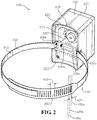
FIG. 2 is a rear perspective view of the leak detector ofFIG. 1 . -
FIG. 3 is an exploded view of the housing ofFIG. 1 . -
FIG. 4 is a sectional view of the housing ofFIG. 2 taken along line 4-4 ofFIG. 1 . -
FIG. 5 is a top view of the leak detector ofFIG. 1 . -
FIG. 6 is a top front perspective view of the strap assembly ofFIG. 1 . -
FIG. 7 is a detail view of the strap assembly ofFIG. 6 taken fromdetail 7 ofFIG. 5 . -
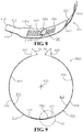
FIG. 8 is a bottom front perspective view of a portion of a strap assembly in accordance with another aspect of the current disclosure. -
FIG. 9 is a top view of the strap assembly ofFIG. 8 . -
FIG. 10 is a detail view of the strap assembly ofFIG. 8 taken fromdetail 10 ofFIG. 9 . -
FIG. 11 is a top rear perspective view of a strap assembly in accordance with another aspect of the current disclosure. -
FIG. 12 is a bottom view of the strap assembly ofFIG. 11 . -
FIG. 13 is a detail view of the strap assembly ofFIG. 12 taken fromdetail 13 ofFIG. 12 . -
FIG. 14 is a detail view of the strap assembly ofFIG. 12 taken fromdetail 14 ofFIG. 12 . -
FIG. 15 is a perspective view of a tamper-proof housing fastener of the housing ofFIG. 1 in accordance with one aspect of the current disclosure. -
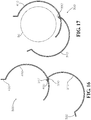
FIG. 16 is a top view of a strap assembly of the leak detector ofFIG. 1 in a first position during installation of the leak detector about a pipe element of a pipe system in accordance with one aspect of the current disclosure. -
FIG. 17 is a top view of a strap assembly of the leak detector ofFIG. 1 in a second position during installation of the leak detector. -
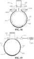
FIG. 18 is a top view of a strap assembly of the leak detector ofFIG. 1 in a third position during installation of the leak detector. -
FIG. 19 is a top view of a strap assembly of the leak detector ofFIG. 1 in a fourth position during installation of the leak detector. - The present invention can be understood more readily by reference to the following detailed description, examples, drawings, and claims, and their previous and following description. However, before the present devices, systems, and/or methods are disclosed and described, it is to be understood that this invention is not limited to the specific devices, systems, and/or methods disclosed unless otherwise specified, as such can, of course, vary. It is also to be understood that the terminology used herein is for the purpose of describing particular aspects only and is not intended to be limiting.
- The following description of the invention is provided as an enabling teaching of the invention in its best, currently known embodiment. To this end, those skilled in the relevant art will recognize and appreciate that many changes can be made to the one aspect of the invention described herein, while still obtaining the beneficial results of the present invention. It will also be apparent that some of the desired benefits of the present invention can be obtained by selecting some of the features of the present invention without utilizing other features. Accordingly, those who work in the art will recognize that many modifications and adaptations to the present invention are possible and can even be desirable in certain circumstances and are a part of the present invention. Thus, the following description is provided as illustrative of the principles of the present invention and not in limitation thereof.
- As used throughout, the singular forms "a," "an" and "the" include plural referents unless the context clearly dictates otherwise. Thus, for example, reference to "a fastener" can include two or more such fasteners unless the context indicates otherwise.
- Ranges can be expressed herein as from "about" one particular value, and/or to "about" another particular value. When such a range is expressed, another aspect comprises from the one particular value and/or to the other particular value. Similarly, when values are expressed as approximations, by use of the antecedent "about," it will be understood that the particular value forms another aspect. It will be further understood that the endpoints of each of the ranges are significant both in relation to the other endpoint, and independently of the other endpoint.
- For purposes of the current disclosure, a material property or dimension measuring about X or substantially X on a particular measurement scale measures within a range between X plus an industry-standard upper tolerance for the specified measurement and X minus an industry-standard lower tolerance for the specified measurement. Because tolerances can vary between different materials, processes and between different models, the tolerance for a particular measurement of a particular component can fall within a range of tolerances.
- As used herein, the terms "optional" or "optionally" mean that the subsequently described event or circumstance may or may not occur, and that the description comprises instances where said event or circumstance occurs and instances where it does not.
- The word "or" as used herein means any one member of a particular list and also comprises any combination of members of that list.
- In one aspect, a monitoring device and associated methods, systems, devices, and various apparatuses are described herein. The monitoring device can be mounted on a pipe system and can comprise a housing and a strap assembly. In one aspect, the monitoring device disclosed herein is, for example and without limitation, a leak detector configured to mount on the pipe system and sense acoustic energy signals traveling therein.
- Various materials can be used to fabricate the various components of the monitoring device. The disclosure of the specific materials or finishes or types of materials or finishes listed, however, is not intended to be limiting on the current disclosure. One of ordinary skill in the art would know to substitute equivalent materials where appropriate.
- In one aspect, as shown in
Figures 1 and2 , amonitoring device 100 for apipe system 90 comprises ahousing 200 and astrap assembly 300, which can also be described as a band. Each of one ormore housing fasteners 400a,b (400a shown inFigure 2 ), which can each be a tamper-resistant fastener, secures thestrap assembly 300 to thehousing 200. Thehousing 200 defines a mounting surface 201 (shown inFigure 2 ) and a pair of mountingreceptacles 208a,b on a mountingside 205 that is opposite to adistal side 207, thehousing 200 configured to mount on an exterior surface of apipe element 95 of thepipe system 90. Thehousing fastener 400a,b can be received within each mounting receptacle 208a,b to secure thestrap assembly 300 to thehousing 200. In one aspect, thestrap assembly 300 comprises afirst strap 310 and asecond strap 410. As shown, thestrap assembly 300 forms a circular shape in an assembled state. The circular shape can be pre-formed into thefirst strap 310 or thesecond strap 410 and can be formed during the assembly and installation processes. In other aspects, thestrap assembly 300 can have a non-circular shape such as, for example and without limitation, that of a rectangle or that of another polygon (e.g., a hexagon or a octagon) or can be otherwise made to fit around apipe element 95 having a non-circular shape. Optionally, thestrap assembly 300 can be composed of a single strap or can be composed of more than two straps. A "pipe element" such as thepipe element 95 can include, for example and without limitation, pipes, valves, meters, fittings, or any other piping structure such as in a pipe system to which a monitoring device such as themonitoring device 100 can be attached. - The
monitoring device 100 can be, for example and without limitation, a leak detector as shown. Themonitoring device 100 can comprise a sensor 230 (shown inFigure 2 ) enclosed in thehousing 200. In one aspect, thesensor 230 is configured to mount on the exterior surface of thepipe element 95 of thepipe system 90. In one aspect, thepipe system 90 comprises a hydrant, the exterior surface ofpipe element 95 of thepipe system 90 being an exterior surface of the hydrant, the mountingsurface 201 shaped to match the exterior surface of the hydrant. As shown, the mountingsurface 201 has a concave shape to match the convex exterior surface of thepipe element 95, although in other aspects the mountingsurface 201 can have a flat shape to match a pipe element having a flat exterior surface or the mountingsurface 201 can have a different shape. - In one aspect, as shown in
Figure 3 , thehousing 200 comprises abody 210, agasket 215, and acover 220. The housing can additionally comprise a controller 240-which can comprise a printed circuit board ("PCB") assembly (shown in a partially exploded state inFigure 3 ), a locatingdevice 250 such as a GPS antenna, acommunications device 260 such as an LTE cellular antenna, adata card 270 such as a SIM card, a data card holder 275 (shown inFigure 4 ), andbatteries 280a,b. As shown inFigure 3 , a plurality offasteners 290 can be used to assemble the components of thehousing 200 in such a way that thehousing 200 cannot be disassembled without first removing thehousing 200 from thestrap assembly 300, removing or loosening themonitoring device 100 from thepipe element 95 to which it is secured, or damaging one or more components of themonitoring device 100. As shown, the head of each of the plurality offasteners 290 is accessible only from the mountingside 205 of thehousing 200 and are thus not accessible when themonitoring device 100 is installed as shown inFigure 1 with the mountingsurface 201 of thehousing 200 contacting thepipe element 95. Thecover 220 can comprise a plurality of threaded inserts (not shown) into which the plurality offasteners 290 can tighten and which can only be removed by damaging thecover 220. Thebatteries 280a,b can be, for example and without limitation, direct-current batteries, and any number of batteries can be present, including zero, one, or more than two batteries. - In one aspect, the
body 210 and thecover 220 define a wet compartment 211 (shown inFigure 2 ) and adry compartment 212. Thewet compartment 211 defines an enclosure and is sized to receive thesensor 230. Thedry compartment 212 defines an enclosure and is sized to receive thecontroller 240, the locatingdevice 250, thecommunications device 260, thedata card 270, and thebatteries 280a,b. Optionally, thedry compartment 212 is sealably isolated from thewet compartment 211 with a potting material. Optionally, thesensor 230 is waterproof. Optionally, thegasket 215 is positioned between thebody 210 and thecover 220 and facilitates a tight seal between thebody 210 and thecover 220. Thegasket 215 may define holes (not shown) to provide clearance for fasteners. Thegasket 215 can be made from a rubber such as, for example and without limitation, Buna-N rubber (i.e., nitrile), ethylene propylene diene monomer (EPDM) rubber, or silicone. Thegasket 215 can also be made of any other rubber, plastic, cork, wood, metal, ceramic, polymer, elastomer, rosin, foam, silicone, any combination of the foregoing materials, or any material suitable for sealing the joint between thebody 210 and thecover 220. - While wiring and other details are not shown in
Figure 3 , various components of thehousing 200 are connected via physical wires or when installed inside thebody 210 are brought into either wired or wireless communication with other components of thehousing 200. As shown, themonitoring device 100 communicates wirelessly with the monitoring system of which it is part. - In one aspect, as shown in
Figures 4 and5 , thehousing 200 comprises the mountingreceptacles 208a,b. Thehousing fastener 400a is shown connecting afirst mounting tab 320 within the first mountingreceptacle 208a of the pair of mountingreceptacles 208a,b, and asecond mounting tab 420 is shown coupled to the second mountingreceptacle 208b of the pair of mountingreceptacles 208a,b, optionally by thehousing fastener 400b. In another aspect, thesecond mounting tab 420 can be lockably coupled to the second mountingreceptacle 208b without aseparate housing fastener 400b. For example and without limitation, thesecond mounting tab 420 can be lockably coupled to the second mountingreceptacle 208b by forming thesecond mounting tab 420 into a barbed connection that can easily enter the second mountingreceptacle 208b but not easily exit the second mountingreceptacle 208b. In such a connection, thesecond mounting tab 420 is not removable without damaging thesecond mounting tab 420 or the second mountingreceptacle 208b. - The mounting
surface 201 is concave in shape but can be of any shape to match, as desired, thepipe element 95 to which thehousing 200 is assembled. Optionally, thefirst mounting tab 320 of thefirst strap 310 defines a mountinghole 325 through which thehousing fastener 400a extends, and thesecond mounting tab 420 of thesecond strap 410 defines a mountinghole 425 through which thehousing fastener 400b extends. Each of the mounting holes 325,425 can elongated, circular, or have a key-hole shape which accommodates a head 401 (shown inFigure 15 ) on a larger end and a threaded portion 402 (shown inFigure 15 ) on a smaller end. As shown, each of thehousing fasteners 400a,b adjustably secures thestrap assembly 300 to thehousing 200. Specifically, atab portion 319 of aninner surface 311 of thefirst strap 310 at thefirst mounting tab 320 and a facingsurface 209a of the first mountingreceptacle 208a of thehousing 200 can define anadjustment distance 206a. Likewise, atab portion 419 of aninner surface 411 of thesecond strap 410 at thesecond mounting tab 420 and a facingsurface 209b of the second mountingreceptacle 208b of thehousing 200 can define anadjustment distance 206b. Each of theadjustment distances 206a,b are gaps that allow thestrap assembly 300 to be adjustably secured to thehousing 200 by further loosening or tightening of therespective housing fasteners 400a,b. The adjustment distances 206a,b allow for fine adjustment of an inner diameter 500 (shown inFigure 5 ) of thestrap assembly 300 during the final steps of installation of themonitoring device 100. For example and without limitation, each of theadjustment distances 206a,b can be about 0.080 inches (2.0 millimeters). In another aspect, however, each of theadjustment distances 206a,b can be less than or greater than this value. -
Figures 5-7 show one variation of thestrap assembly 300. As shown inFigure 6 , thefirst strap 310 comprises a first mountingend 315, a first adjustingend 317 distally located from the first mountingend 315, and a firstintermediate portion 316 therebetween. Thefirst strap 310 comprises thefirst mounting tab 320 proximate to the first mountingend 315 and an insert tab 330 (shown inFigure 7 ) proximate to the first adjustingend 317. Also shown inFigure 6 , thesecond strap 410 comprises a second mountingend 415, asecond adjusting end 417 distally located from the second mountingend 415, and a secondintermediate portion 416 therebetween. Thesecond strap 410 comprises thesecond mounting tab 420 proximate to the second mountingend 415. One or more edges of thefirst strap 310 or thesecond strap 410 at the respective adjusting ends 317,417 or at a transition between the adjusting ends 317,417 and the intermediate portions 316,416 can comprise a chamfer or a radius. - As shown in
Figure 6 , thesecond strap 410 defines a plurality ofadjustment slots 430 proximate to thesecond adjusting end 417. Eachadjustment slot 430 is aligned in an axial direction along anaxis 510 of the strap assembly and sized to lockably receive a portion of theinsert tab 330 in any one of a plurality of insert positions 435 such asinsert positions 435a,b,c. The portion of theinsert tab 330 is lockably received in theadjustment slot 430 when the portion is inserted into theadjustment slot 430 and positioned such that the portion cannot be removed from theadjustment slot 430 without significantly repositioning thefirst strap 310 and thesecond strap 410 relative to each other or damaging one or both of thefirst strap 310 and thesecond strap 410. Eachadjustment slot 430 has a length in an axial direction that is slightly longer than a width in an axial direction of theinsert tab 330 of thefirst strap 310. For example and without limitation, eachadjustment slot 430 has a width in a circumferential direction of 0.074 inches (1.9 millimeters). Thus each insert position 435 corresponds to a different inner diameter 500 (shown inFigure 5 ) of thestrap assembly 300 when themonitoring device 100 is tightened. Insert positions 435 may be individually separated by a pitch 437 (shown inFigure 2 ) and may be separated by a separation distance 439 (shown inFigure 2 ) into groups of slots (for example and without limitation, groups of ten slots each) to ease identification of a particular insert position 435. Thepitch 437 and theseparation distance 439 need not be constant around the circumference of thesecond strap 410. The number of insert positions 435 is limited only by the length of thesecond strap 410 and the spacing between each insert position 435. As shown, a portion of thefirst strap 310 proximate to the first adjustingend 317 crosses a portion of thesecond strap 410 proximate to thesecond adjusting end 417, and a portion of thefirst strap 310 is positioned radially inside thesecond adjusting end 417 of thesecond strap 410 relative to theaxis 510. When themonitoring device 100 is tightened, theinsert tab 330 is lockably coupled to thesecond strap 410 and cannot be removed without loosening themonitoring device 100. - As shown in
Figure 7 , theinsert tab 330 of thefirst strap 310 has a semicircular-shapedlocking portion 335 defining aradiused portion 333 and has been inserted into one of theadjustment slots 430 of thesecond strap 410 through anouter surface 412 of thesecond strap 410. In its final assembled position relative thesecond strap 410, theinner surface 311 of a portion of thefirst strap 310 is substantially facing anouter surface 412 of thesecond strap 410 such that a portion of thefirst strap 310 rests along and radially outside thesecond strap 410 relative to theaxis 510. Because theinsert tab 330 is hooked through one of the plurality ofadjustment slots 430, tensile forces on the ends of thestrap assembly 300 that would otherwise separate thefirst strap 310 from thesecond strap 410 cause only a lockingsurface 331 of theinsert tab 330 to bear against a side of theadjustment slot 430 in which theinsert tab 330 is inserted. Theinsert tab 330 can be formed such that in an assembled state agap 337 exists between the first adjustingend 317 of thefirst strap 310 and theinner surface 411 of thesecond strap 410. Optionally, the pitch 437 (shown inFigure 2 ) can be set such that a portion of the first adjustingend 317 of thefirst strap 310 extends through anadjustment slot 430 when thestrap assembly 300 is assembled around thepipe element 95 of thepipe system 90. -
Figures 8-10 show another variation of thestrap assembly 300. As shown inFigure 8 , theinsert tab 330 is L-shaped and has aflat locking portion 335 inserted into one of theadjustment slots 430 of thesecond strap 410. As shown inFigure 9 , thefirst mounting tab 320 is angled with respect to a portion of the firstintermediate portion 316 adjacent to thefirst mounting tab 320 by an angle A1, and thesecond mounting tab 420 is angled with respect to a portion of the secondintermediate portion 416 adjacent to thesecond mounting tab 420 by an angle A2. Thefirst mounting tab 320 and thesecond mounting tab 420 are parallel so that they can be inserted into the respective first mountingreceptacle 208a and the second mountingreceptacle 208b. As shown inFigure 10 , tensile forces on the ends of thestrap assembly 300 cause thelocking surface 331 of theinsert tab 330 to again bear against a side of theadjustment slot 430 in which theinsert tab 330 is assembled. -
Figures 11-14 show another variation of thestrap assembly 300. As shown inFigure 11 , theinsert tab 330 has a semicircular-shapedlocking portion 335 inserted into one of theadjustment slots 430 of thesecond strap 410 through theinner surface 411 of thesecond strap 410. Additionally, alocking clip 440 is formed into thesecond strap 410 proximate to thesecond adjustment end 417. Thelocking clip 440 is made to cross and lockably couple with the narrowerfirst strap 310. Such engagement of thelocking clip 440 with thefirst strap 310 is possible with sufficient looseness of theinsert tab 330 within theadjustment slot 430 into which it is inserted. For example and without limitation, thelocking clip 440 of thesecond strap 410 defines aslot 442 that is sized to lockably receive a portion thefirst strap 310. In its final assembled position relative thesecond strap 410, theouter surface 312 of a portion of thefirst strap 310 is substantially facing aninner surface 411 of thesecond strap 410 such that a portion of thefirst strap 310 rests along and radially inside thesecond strap 410 relative to theaxis 510. As shown inFigure 14 , tensile forces on the ends of thestrap assembly 300 cause thelocking surface 331 of theinsert tab 330 to again bear against a side of theadjustment slot 430 in which theinsert tab 330 is assembled. - In one aspect, each of the first adjusting
end 317, thesecond adjusting end 417, the firstintermediate portion 316, and the secondintermediate portion 416 has an axial length measured in an axial direction along theaxis 510 of thestrap assembly 300. A first axial length of the first adjustingend 317 is greater than a first strap thickness 313 (shown inFigure 4 ) of the first adjustingend 317 and a second axial length of thesecond adjusting end 417 is greater than a second strap thickness 413 (shown inFigure 4 ) of thesecond adjusting end 417. In another aspect, the first axial length or the second axial length is less than or equal to thefirst strap thickness 313 and thesecond strap thickness 413, respectively. As shown in each variation of thestrap assembly 300, each of theadjustment slots 430 of thesecond strap 410 are aligned in an axial direction along theaxis 510 of thestrap assembly 300. - In one aspect, as shown in
Figure 15 , thehousing fastener 400, which comprises the head 401 and the threadedportion 402, is a tamper-resistant fastener and thus resists unfastening without a special removal tool. Fasteners that are tamper-resistant include, for example and without limitation, Pin in Torx fasteners, Pin in Hex fasteners, Drilled Spanner fasteners, One Way fasteners, Philips Pin-Head fasteners, High-Security Drive fasteners including an irregular or custom shape, Tri-Groove fasteners, TRI WING fasteners, and TP3 triangular recessed-drive fasteners. A fastener such as thehousing fastener 400, including both tamper-resistant and non-tamper-resistant versions can comprise, for example and without limitation, clockwise threads or counterclockwise threads (such as an OPSIT reverse-thread fastener) and can have full threads or partial threads, with or without a shoulder. Thehousing fastener 400, including both tamper-resistant and non-tamper-resistant versions, can have, for example and without limitation, a truss head, a pan head, a round head, a button head, a flat head, or a countersunk head. A tamper-resistant fastener can also be described as a tamper-proof fastener or a security fastener. The fastener shown inFigure 15 is a Tri-Groove tamper-proof fastener with full threads, no shoulder, and a button head. - In one aspect, as shown in
Figure 16 , a method for installing themonitoring device 100 on thepipe system 90 comprises coupling the first adjustingend 317 of thefirst strap 310 of thestrap assembly 300 to thesecond strap 410 of thestrap assembly 300 by inserting theinsert tab 330 of thefirst strap 310 into a one of the plurality ofadjustment slots 430 defined on thesecond strap 410, each of the plurality ofadjustment slots 430 sized to lockably receive a portion of theinsert tab 330 in any one of a plurality of insert positions 435. As shown inFigure 17 , the method additionally comprises substantially encircling the exterior surface of thepipe element 95 of thepipe system 90 with thestrap assembly 300 by rotating thefirst strap 310 relative to thesecond strap 420 about the insert position 435. As shown inFigure 18 , the method additionally comprises coupling thehousing 200 to thestrap assembly 300 by installing thehousing fastener 400a through thefirst mounting tab 320 of thefirst strap 310 of thestrap assembly 300 and into the mountingreceptacle 208a of thehousing 200. The method additionally comprises coupling thehousing 200 to thestrap assembly 300 by installing thehousing fastener 400b through thesecond mounting tab 420 of thesecond strap 410 of thestrap assembly 300 and into the mountingreceptacle 208b of thehousing 200. The gaps between thepipe element 95 and thestrap assembly 300 are shown exaggerated inFigure 18 . - As shown in
Figure 19 , the method comprises tightening thestrap assembly 300 against an exterior surface of thepipe element 95 of thepipe system 90 by tightening one or more of thehousing fasteners 400a,b as shown with atightening tool 1900 having abit 1910 matching the head of thehousing fasteners 400a,b. In the case of certain types of tamper-proof fasteners other than thehousing fastener 400 shown inFigure 15 , removing thehousing fastener 400a,b requires a tool other than thetightening tool 1900 with the bit 1910 (i.e., by drilling out the fastener as in the case of a One Way tamper-proof fastener). The method can further comprise tightening thehousing fastener 400a,b from a fully engaged first position to a fully engaged second position by reducing theadjustment distances 206a,b, bringing the respective mounting tabs 320,420 towards each other and thereby reducing theinner diameter 500 of thestrap assembly 300. In one aspect, as shown inFigure 4 , thehousing fastener 400a,b is fully engaged when it extends inside the housing 200 a sufficient distance to secure thehousing fastener 400a,b in place relative to thehousing 200, even if thehousing fastener 400a,b can be further tightened. Optionally, the method further comprises mounting themonitoring device 100 to a hydrant such as a fire hydrant, the exterior surface of thepipe system 90 being an exterior surface of the hydrant. - The method can further comprise mounting the
sensor 230 to the exterior surface of thepipe element 95 of thepipe system 90 with an adhesive material such as a metal-filled epoxy before encircling the exterior surface of thepipe element 95 of thepipe system 90 with thestrap assembly 300. In one aspect, metal fragments in the epoxy will facilitate the transmission of acoustic energy signals such as vibrations in thepipe system 90 to thesensor 230. In another aspect, an epoxy not containing metal fragments or another adhesive may be used. During the mounting process, thesensor 230 will typically be brought as close to the exterior surface of thepipe element 95 as possible to minimize the gap between the exterior surface of thepipe element 95 and thesensor 230. The thickness of the adhesive material used can vary to fill in the gap between the exterior surface of thepipe element 95 and thesensor 230 and will typically be only as thick as required to bridge the gap. After mounting thesensor 230 to thepipe element 95, thehousing 200 is placed over thesensor 230. In another aspect, thesensor 230 can be mounted to thepipe element 95 as thehousing 200 is itself simultaneously mounted to thepipe element 95. In such an aspect, the sensor can be held in position relative to thehousing 200 by thehousing 200 and a compressible gasket material or a spring or thebody 210 of thehousing 200 can be used to hold thesensor 230 tight against the exterior surface of thepipe element 95. Thesensor 230 can be already wired to thehousing 200 or configured to connect to thehousing 200 after mounting of thesensor 230. As previously discussed, thesensor 230 can be configured to sense acoustic energy signals traveling inside thepipe system 90. - In one aspect, as shown in
Figure 18 , coupling thehousing 200 to thestrap assembly 300 is performed after coupling thefirst strap 310 of thestrap assembly 300 to thesecond strap 410 of thestrap assembly 300. Coupling thehousing 200 to both thefirst strap 310 and thesecond strap 410 of thestrap assembly 300 after coupling thefirst strap 310 to thesecond strap 410 makes it more difficult to disengage thefirst strap 310 from thesecond strap 410 and therefore makes themonitoring device 100 more resistant to tampering. Once thehousing 200 is coupled to both thefirst strap 310 and thesecond strap 410, disengaging thefirst strap 310 from thesecond strap 410 becomes more difficult because rotating thefirst strap 310 relative to thesecond strap 410 to remove theinsert tab 330 from the insert position 435 is not typically possible without cutting or otherwise damaging thefirst strap 310, thesecond strap 410, or thehousing 200. In another aspect, thehousing 200 can be first coupled to a one of thefirst strap 310 and thesecond strap 410 but not both thefirst strap 310 and thesecond strap 410 before coupling thefirst strap 310 to thesecond strap 410. In subsequent steps, thefirst strap 310 can be coupled to thesecond strap 410 and then thehousing 200 can be coupled to the one of thefirst strap 310 and thesecond strap 410 to which thehousing 200 is not already coupled. In one aspect, themonitoring device 100 is removed from thepipe element 95 of thepipe system 90 only by a one of damaging a portion of themonitoring device 100 and uninstalling a one of thefirst housing fastener 400a and thesecond housing fastener 400b. - Components of the
pipe system 90 including thepipe element 95 can be made from, for example and without limitation, a metal such as ductile iron or another cast iron , steel, or a non-metallic materials such as polyvinyl chloride (PVC). Thebody 210 and thecover 220 can be made from, for example and without limitation, fiber-reinforced plastic. - The
first strap 310 and thesecond strap 410 of thestrap assembly 300 can be made from, for example and without limitation, a metal such as steel, copper, or bronze; a non-metallic material such as a polyamide plastic or a polypropylene plastic; or a variety of other non-elastomeric materials. For example and without limitation, each of thefirst strap 310 and thesecond strap 410 can be formed from an AISI 304 L series stainless steel having a thickness of 0.040 inches (1.0 millimeters). - The components of the
strap assembly 300 can be formed from a flat blank of raw material using one or more material removal processes such as, for example and without limitation, machining, stamping, punching, laser-cutting, abrasive-water-jet-cutting, and chemical milling or etching. Optionally, such a material removal process can be used in combination with forming processes such as, for example and without limitation, casting, forging, stamping, bending, and three-dimensional printing. - For example and without limitation, each of the
housing fasteners 400 can be tightened until thestrap assembly 300 and the mounting side of thehousing 200 are snug (i.e., held flush) against the exterior surface of thepipe element 95 of thepipe system 90. Optionally, each of thehousing fasteners 400 can be additionally tightened past this point. None of thehousing fasteners 400, however, is typically tightened so much that thestrap assembly 300 or thehousing 200 is damaged. - As a leak detector, the
sensor 230 of themonitoring device 100 can be configured to sense acoustic energy signals traveling in thepipe system 90 which would indicate that fluid is traveling through thepipe system 90 even when it should not or when fluid is escaping the pipe system, such as in a pipe burst situation. Such monitoring can be performed by a monitoring system such as the Mi.Echo system available from Mueller Systems. Themonitoring device 100 can also be used to monitor the condition of walls of apipe system 90, can monitor whether thepipe system 90 has been tampered with, can monitor temperature, or can monitor characteristics of fluid flow within thepipe system 90 in order to identify transient effects such as pressure surges and water hammer. - In one exemplary aspect, a monitoring device for a pipe system can comprise a housing defining a mounting surface and a pair of mounting receptacles on a mounting side. The housing can be configured to mount on an exterior surface of a pipe element of the pipe system. The monitoring device can further comprise a tamper-resistant housing fastener and a strap assembly. The housing fastener can be received within a first mounting receptacle of the pair of mounting receptacles to secure the strap assembly to the housing. The strap assembly can comprise a first strap and a second strap. The first strap can comprise a first mounting end, a first adjusting end distally located from the first mounting end, and an intermediate portion therebetween, the first strap comprising a first mounting tab proximate to the first mounting end. The first strap can further comprise an insert tab proximate to the first adjusting end, the housing fastener connecting the first mounting tab within the first mounting receptacle. The second strap can comprise a second mounting end, a second adjusting end distally located from the second mounting end, and a second intermediate portion therebetween, the second strap comprising a second mounting tab proximate to the second mounting end. The second mounting tab can be coupled to a second mounting receptacle of the pair of mounting receptacles. The second strap can define a plurality of adjustment slots proximate to the second adjusting end, each adjustment slot aligned in an axial direction of the strap assembly and sized to lockably receive a portion of the insert tab in any one of a plurality of insert positions. Each insert position can correspond to a different inner diameter of the strap assembly when the monitoring device is tightened. A portion of the first strap proximate to the first adjusting end can cross a portion of the second strap proximate to the second adjusting end and a portion of the first strap positioned radially inside the second adjusting end of the second strap. The insert tab can be lockably coupled to the second strap when the monitoring device is tightened.
- In a further exemplary aspect, the monitoring device can be a leak detector comprising a sensor. In yet another aspect, the mounting surface can be concave in shape. In still another aspect, the first mounting tab can define a mounting hole through which the housing fastener extends. In another aspect, the housing fastener can adjustably secure the first mounting tab of the strap assembly within the housing, an inner surface of the first mounting tab and a facing surface of the first mounting receptacle of the housing defining an adjustment distance.
- In another exemplary aspect, the monitoring device can comprise a housing configured to mount on an exterior surface of a pipe element of the pipe system; a housing fastener; and a strap assembly coupled to the housing with the housing fastener. The housing fastener can be received within the housing to secure the strap assembly to the housing. The strap assembly can comprise a first strap and a second strap. The first strap can comprise a first mounting end, a first adjusting end distally located from the first mounting end, and a first intermediate portion therebetween, the first strap comprising an insert tab proximate to the first adjusting end. The second strap can comprise a second mounting end, a second adjusting end distally located from the second mounting end, and a second intermediate portion therebetween, the second strap comprising a plurality of adjustment slots sized to lockably receive a portion of the insert tab in any one of a plurality of insert positions. The insert tab can be lockably coupled to the second strap when the monitoring device is tightened.
- In another exemplary aspect, the monitoring device can comprise a sensor enclosed in the housing. In yet another aspect, the sensor can be configured to mount on the exterior surface of the pipe element of the pipe system to sense acoustic energy signals traveling in the pipe system. In still another aspect, each of the first adjusting end, the second adjusting end, the first intermediate portion, and the second intermediate portion can have an axial length measured in an axial direction of the strap assembly. In such aspect, a first axial length of the first adjusting end can be greater than a first strap thickness of the first adjusting end and a second axial length of the second adjusting end can be greater than a second strap thickness of the second adjusting end. In another aspect, the adjustment slots of the second strap can be aligned in an axial direction of the strap assembly. In another aspect, the housing fastener can adjustably secure the strap assembly to the housing, an inner surface of the first strap and a facing surface of a mounting receptacle of the housing defining an adjustment distance.
- In another exemplary aspect, disclosed is a method for installing a monitoring device on a pipe system. The monitoring device can comprise a strap assembly and a housing. The method can comprise coupling an adjusting end of a first strap of the strap assembly to a second strap of the strap assembly by inserting an insert tab of the first strap into a one of a plurality of adjustment slots defined on the second strap, each of the plurality of adjustment slots sized to lockably receive a portion of the insert tab in any one of a plurality of insert positions. The method can further comprise coupling the housing to the strap assembly by installing a housing fastener through the strap assembly and into a mounting receptacle of the housing. The method can further comprise tightening the strap assembly against an exterior surface of a pipe element of the pipe system by tightening the housing fastener.
- In another exemplary aspect, the method for installing a monitoring device on a pipe system can further comprise mounting the monitoring device to a hydrant, the exterior surface of the pipe system being an exterior surface of the hydrant. In yet another aspect, the method can further comprise mounting a sensor to the exterior surface of the pipe element of the pipe system, the sensor configured to sense acoustic energy signals traveling inside the pipe system. In still another aspect, the method can further comprise substantially encircling the exterior surface of the pipe element of the pipe system with the strap assembly. In another aspect, coupling the housing to the strap assembly can comprise installing the housing fastener through a first mounting tab of the first strap and into the mounting receptacle of the housing.
- In another exemplary aspect, the method can further comprise tightening the housing fastener from a fully engaged first position to a fully-engaged second position and thereby reducing an inner diameter of the strap assembly. In another aspect, coupling the housing to the strap assembly can be performed after coupling the adjusting end of the first strap of the strap assembly to the second strap of the strap assembly. In another aspect, the housing fastener can be a tamper-proof fastener. In another aspect, the monitoring device can be removed from the pipe element of the pipe system only by a one of damaging a portion of the monitoring device and uninstalling the housing fastener.
- In another exemplary aspect, the monitoring device can comprise a housing configured to mount on the pipe system; and a strap assembly coupled to the housing. The strap assembly can comprise a first strap and a second strap lockably coupled to the first strap.
- One should note that conditional language, such as, among others, "can," "could," "might," or "may," unless specifically stated otherwise, or otherwise understood within the context as used, is generally intended to convey that certain embodiments include, while other embodiments do not include, certain features, elements and/or steps. Thus, such conditional language is not generally intended to imply that features, elements and/or steps are in any way required for one or more particular embodiments or that one or more particular embodiments necessarily include logic for deciding, with or without user input or prompting, whether these features, elements and/or steps are included or are to be performed in any particular embodiment.
- It should be emphasized that the above-described embodiments are merely possible examples of implementations, merely set forth for a clear understanding of the principles of the present disclosure. Any process descriptions or blocks in flow diagrams should be understood as representing modules, segments, or portions of code which include one or more executable instructions for implementing specific logical functions or steps in the process, and alternate implementations are included in which functions may not be included or executed at all, may be executed out of order from that shown or discussed, including substantially concurrently or in reverse order, depending on the functionality involved, as would be understood by those reasonably skilled in the art of the present disclosure. Many variations and modifications may be made to the above-described embodiment(s) without departing substantially from the spirit and principles of the present disclosure. Further, the scope of the present disclosure is intended to cover any and all combinations and sub-combinations of all elements, features, and aspects discussed above. All such modifications and variations are intended to be included herein within the scope of the present disclosure, and all possible claims to individual aspects or combinations of elements or steps are intended to be supported by the present disclosure.
- In the following there will be described example embodiments of general principles of the application:
- Example 1. A monitoring device for a pipe system, the monitoring device comprising:
- a housing defining a mounting surface and a pair of mounting receptacles on a mounting side, the housing configured to mount on an exterior surface of a pipe element of the pipe system;
- a tamper-resistant housing fastener; and
- a strap assembly, the housing fastener received within a first mounting receptacle of the pair of mounting receptacles to secure the strap assembly to the housing, the strap assembly comprising a first strap and a second strap,
- the first strap comprising a first mounting end, a first adjusting end distally located from the first mounting end, and an intermediate portion therebetween, the first strap comprising a first mounting tab proximate to the first mounting end, the first strap further comprising an insert tab proximate to the first adjusting end, the housing fastener connecting the first mounting tab within the first mounting receptacle;
- the second strap comprising a second mounting end, a second adjusting end distally located from the second mounting end, and a second intermediate portion therebetween, the second strap comprising a second mounting tab proximate to the second mounting end, the second mounting tab coupled to a second mounting receptacle of the pair of mounting receptacles, the second strap defining a plurality of adjustment slots proximate to the second adjusting end, each adjustment slot aligned in an axial direction of the strap assembly and sized to lockably receive a portion of the insert tab in any one of a plurality of insert positions, each insert position corresponding to a different inner diameter of the strap assembly when the monitoring device is tightened, a portion of the first strap proximate to the first adjusting end crossing a portion of the second strap proximate to the second adjusting end and a portion of the first strap positioned radially inside the second adjusting end of the second strap, the insert tab lockably coupled to the second strap when the monitoring device is tightened.
- Example 2. The monitoring device of Example 1, wherein the monitoring device is a leak detector comprising a sensor.
- Example 3. The monitoring device of Example 1, wherein the mounting surface is concave in shape.
- Example 4. The monitoring device of Example 1, wherein the first mounting tab defines a mounting hole through which the housing fastener extends.
- Example 5. The monitoring device of Example 1, wherein the housing fastener adjustably secures the first mounting tab of the strap assembly within the housing, an inner surface of the first mounting tab and a facing surface of the first mounting receptacle of the housing defining an adjustment distance.
- Example 6. A monitoring device for a pipe system, the monitoring device comprising:
- a housing configured to mount on an exterior surface of a pipe element of the pipe system;
- a housing fastener; and
- a strap assembly coupled to the housing with the housing fastener, the housing fastener received within the housing to secure the strap assembly to the housing, the strap assembly comprising a first strap and a second strap,
- the first strap comprising a first mounting end, a first adjusting end distally located from the first mounting end, and a first intermediate portion therebetween, the first strap comprising an insert tab proximate to the first adjusting end;
- the second strap comprising a second mounting end, a second adjusting end distally located from the second mounting end, and a second intermediate portion therebetween, the second strap comprising a plurality of adjustment slots sized to lockably receive a portion of the insert tab in any one of a plurality of insert positions, the insert tab lockably coupled to the second strap when the monitoring device is tightened.
- Example 7. The monitoring device of Example 6, wherein the monitoring device comprises a sensor enclosed in the housing.
- Example 8. The monitoring device of Example 7, wherein the sensor is configured to mount on the exterior surface of the pipe element of the pipe system to sense acoustic energy signals traveling in the pipe system.
- Example 9. The monitoring device of Example 6, wherein each of the first adjusting end, the second adjusting end, the first intermediate portion, and the second intermediate portion has an axial length measured in an axial direction of the strap assembly, and wherein a first axial length of the first adjusting end is greater than a first strap thickness of the first adjusting end and a second axial length of the second adjusting end is greater than a second strap thickness of the second adjusting end.
- Example 10. The monitoring device of Example 6, wherein the adjustment slots of the second strap are aligned in an axial direction of the strap assembly.
- Example 11. The monitoring device of Example 6, wherein the housing fastener adjustably secures the strap assembly to the housing, an inner surface of the first strap and a facing surface of a mounting receptacle of the housing defining an adjustment distance.
- Example 12. A method for installing a monitoring device on a pipe system, the monitoring device comprising a strap assembly and a housing, the method comprising:
- coupling an adjusting end of a first strap of the strap assembly to a second strap of the strap assembly by inserting an insert tab of the first strap into a one of a plurality of adjustment slots defined on the second strap, each of the plurality of adjustment slots sized to lockably receive a portion of the insert tab in any one of a plurality of insert positions;
- coupling the housing to the strap assembly by installing a housing fastener through the strap assembly and into a mounting receptacle of the housing; and
- tightening the strap assembly against an exterior surface of a pipe element of the pipe system by tightening the housing fastener.
- Example 13. The method of Example 12, further comprising mounting the monitoring device to a hydrant, the exterior surface of the pipe system being an exterior surface of the hydrant.
- Example 14. The method of Example 12, further comprising mounting a sensor to the exterior surface of the pipe element of the pipe system, the sensor configured to sense acoustic energy signals traveling inside the pipe system.
- Example 15. The method of Example 12, further comprising substantially encircling the exterior surface of the pipe element of the pipe system with the strap assembly.
- Example 16. The method of Example 12, wherein coupling the housing to the strap assembly comprises installing the housing fastener through a first mounting tab of the first strap and into the mounting receptacle of the housing.
- Example 17. The method of Example 16, further comprising tightening the housing fastener from a fully engaged first position to a fully-engaged second position and thereby reducing an inner diameter of the strap assembly.
- Example 18. The method of Example 12, wherein coupling the housing to the strap assembly is performed after coupling the adjusting end of the first strap of the strap assembly to the second strap of the strap assembly.
- Example 19. The method of Example 12, wherein the housing fastener is a tamper-proof fastener.
- Example 20. The method of Example 12, wherein the monitoring device is removed from the pipe element of the pipe system only by a one of damaging a portion of the monitoring device and uninstalling the housing fastener.
- Example 21. A monitoring device for a pipe system, the monitoring device comprising:
- a housing configured to mount on the pipe system; and
- a strap assembly coupled to the housing, the strap assembly comprising a first strap and a second strap lockably coupled to the first strap.
Claims (15)
- A monitoring device for a pipe system, the monitoring device comprising:a housing defining a mounting surface and a pair of mounting receptacles on a mounting side, the housing configured to mount on an exterior surface of a pipe element of the pipe system, the housing comprisinga housing body,a housing cover,a cover fastener securing the housing cover to the housing body,a sensor,a controller, anda communications device, the sensor, the controller, and the communications device housed within the housing body and the cover;a tamper-resistant housing fastener configured to resist unfastening without a special removal tool; anda strap assembly comprising a mounting tab, the strap assembly secured to the housing by receiving the housing fastener through the mounting tab and within a first mounting receptacle of the pair of mounting receptacles.
- The monitoring device of claim 1, wherein the controller is a printed circuit board.
- The monitoring device of claim 1, wherein the communications device is an LTE cellular antenna.
- The monitoring device of claim 1, wherein the housing further comprises a data card holder or a locating device.
- The monitoring device of claim 4, wherein the locating device is a GPS antenna.
- The monitoring device of claim 1, wherein the sensor is a leak detector.
- The monitoring device of claim 1, wherein the housing body is configured to cover the first mounting tab and the second mounting tab and expose a head of the housing fastener, whereby the housing body is configured to protect the strap assembly from disassembly without using the special removal tool.
- The monitoring device of claim 1, wherein the strap assembly further comprises a first strap and a second strap.
- The monitoring device of claim 8, wherein:the mounting tab comprises a first mounting tab and a second mounting tab;the first strap comprises a first mounting end, a first adjusting end distally located from the first mounting end, and an intermediate portion therebetween, wherein the first strap further comprises the first mounting tab proximate to the first mounting end and an insert tab proximate to the first adjusting end, wherein the first mounting tab is coupled to a first mounting receptacle of the pair of mounting receptacles; andthe second strap comprises a second mounting end, a second adjusting end distally located from the second mounting end, and a second intermediate portion therebetween, wherein the second strap further comprises the second mounting tab proximate to the second mounting end and the second mounting tab coupled to a second mounting receptacle of the pair of mounting receptacles, wherein the second strap definines a plurality of adjustment slots proximate to the second adjusting end, wherein each adjustment slot is aligned in an axial direction of the strap assembly and sized to lockably receive a portion of the insert tab in any one of a plurality of insert positions, wherein each insert position corresponds to a different inner diameter of the strap assembly when the housing fastener is tightened, wherein a portion of the first strap proximate to the first adjusting end crosses a portion of the second strap proximate to the second adjusting end, and wherein a portion of the first strap is positioned radially inside the second adjusting end of the second strap, the insert tab lockably coupled to the second strap when the housing fastener is tightened.
- The monitoring device of any of claims 1 through 9, wherein the cover fastener is configured to prevent disassembly of the housing cover from the housing body without first removing the housing fastener.
- The monitoring device of claim 10, wherein the housing body is configured to cover the first mounting tab and the second mounting tab and expose a head of the housing fastener, whereby the housing body is configured to protect the strap assembly from disassembly without using the special removal tool.
- The monitoring device of any of claims 9 through 10, wherein the insert tab comprises a semicircular-shaped locking portion, the insert tab inserted into one of the adjustment slots through an outer surface of the second strap.
- The monitoring device of claim 12, wherein a tip of the insert tab extends outward through an adjustment slot adjacent to the adjustment slot through which the insert tab was inserted.
- The monitoring device of claim 9, wherein the insert tab comprises an L-shaped flat locking portion, the insert tab inserted into one of the adjustment slots through an outer surface of the second strap.
- The monitoring device of claim 9, wherein:the insert tab comprises a semicircular-shaped locking portion, the insert tab inserted into one of the adjustment slots through an inner surface of the second strap; andthe second adjustment end comprises a locking clip, the locking clip configured to cross and lockably couple with the first strap.
Applications Claiming Priority (3)
| Application Number | Priority Date | Filing Date | Title |
|---|---|---|---|
| US15/056,329 US10048159B2 (en) | 2016-02-29 | 2016-02-29 | Adjustable hydrant strap |
| PCT/US2016/021687 WO2017151152A1 (en) | 2016-02-29 | 2016-03-10 | Adjustable hydrant strap |
| EP16892896.8A EP3426932B1 (en) | 2016-02-29 | 2016-03-10 | Adjustable hydrant strap |
Related Parent Applications (1)
| Application Number | Title | Priority Date | Filing Date |
|---|---|---|---|
| EP16892896.8A Division EP3426932B1 (en) | 2016-02-29 | 2016-03-10 | Adjustable hydrant strap |
Publications (2)
| Publication Number | Publication Date |
|---|---|
| EP3885587A1 true EP3885587A1 (en) | 2021-09-29 |
| EP3885587B1 EP3885587B1 (en) | 2022-10-12 |
Family
ID=59680061
Family Applications (3)
| Application Number | Title | Priority Date | Filing Date |
|---|---|---|---|
| EP21168025.1A Active EP3885587B1 (en) | 2016-02-29 | 2016-03-10 | Adjustable hydrant strap |
| EP16892896.8A Active EP3426932B1 (en) | 2016-02-29 | 2016-03-10 | Adjustable hydrant strap |
| EP21168030.1A Active EP3943760B1 (en) | 2016-02-29 | 2016-03-10 | Monitoring device for a pipe system |
Family Applications After (2)
| Application Number | Title | Priority Date | Filing Date |
|---|---|---|---|
| EP16892896.8A Active EP3426932B1 (en) | 2016-02-29 | 2016-03-10 | Adjustable hydrant strap |
| EP21168030.1A Active EP3943760B1 (en) | 2016-02-29 | 2016-03-10 | Monitoring device for a pipe system |
Country Status (4)
| Country | Link |
|---|---|
| US (3) | US10048159B2 (en) |
| EP (3) | EP3885587B1 (en) |
| CA (3) | CA3210443A1 (en) |
| WO (1) | WO2017151152A1 (en) |
Families Citing this family (9)
| Publication number | Priority date | Publication date | Assignee | Title |
|---|---|---|---|---|
| US10048159B2 (en) | 2016-02-29 | 2018-08-14 | Mueller International, Llc | Adjustable hydrant strap |
| US20180340557A1 (en) * | 2017-05-26 | 2018-11-29 | Ideal Clamp Products, Inc. | Hose clamp with indicator |
| CN109812522B (en) * | 2017-11-22 | 2020-11-13 | 江苏恒力制动器制造有限公司 | Sensor joint locking mechanism |
| CN108916658B (en) * | 2018-06-06 | 2023-06-16 | 中国特种设备检测研究院 | Multifunctional in-pipeline detector test platform |
| CN110469780B (en) * | 2019-07-26 | 2024-07-26 | 中国石油天然气集团公司管材研究所 | Variable diameter sensor mounting and protecting unit and device for monitoring multi-specification pipelines |
| MX2023000837A (en) * | 2021-08-02 | 2023-06-22 | Catrak Tech Inc | Catalytic converter theft prevention and recovery. |
| CN115703310A (en) * | 2021-08-06 | 2023-02-17 | 建大工业股份有限公司 | tires equipped with sensors |
| US12305559B2 (en) * | 2023-11-10 | 2025-05-20 | Vsi, Llc | Catalytic converter locking device and assembly |
| GB2641235A (en) * | 2024-05-20 | 2025-11-26 | Fido Tech Ltd | A water leak detection system |
Citations (6)
| Publication number | Priority date | Publication date | Assignee | Title |
|---|---|---|---|---|
| EP0437211A1 (en) * | 1990-01-09 | 1991-07-17 | Aug. Winkhaus GmbH & Co. KG | Retention device for fixing an extension part on a carrying rod |
| DE4304239A1 (en) * | 1993-02-12 | 1994-08-18 | Rixen & Kaul Gmbh | Fastening device for fittings on tubes and bars |
| FR2833346A1 (en) * | 2001-12-06 | 2003-06-13 | Jules Richard Instr Sa | Piped fluid temperature monitor, for use in e.g. chemical, nuclear and petrochemical industries, comprises sensor and electronic module in housing with surface that fits against outer wall of pipe |
| US20120006084A1 (en) * | 2008-06-23 | 2012-01-12 | Paul Joseph Weber | Electronic article security system |
| US20140161151A1 (en) * | 2012-12-12 | 2014-06-12 | John Proctor | Line & pipe flexible temperature sensor assembly |
| US20150137982A1 (en) * | 2013-11-19 | 2015-05-21 | Tristram C. Dunn | Sewer alarm apparatus |
Family Cites Families (22)
| Publication number | Priority date | Publication date | Assignee | Title |
|---|---|---|---|---|
| US2158802A (en) * | 1938-04-19 | 1939-05-16 | Osgood M Redlon | Pipe hanger |
| US2466247A (en) * | 1947-03-14 | 1949-04-05 | John A Land | Pipe hanger |
| US2681197A (en) * | 1950-08-22 | 1954-06-15 | Elmer A Johnson | Pipe support |
| US3038230A (en) | 1959-05-12 | 1962-06-12 | Henning Wolfgang | Pipe strap or hose clamp |
| US4044428A (en) | 1975-09-08 | 1977-08-30 | B-Line Systems, Inc. | Conduit clamp |
| US4069433A (en) * | 1976-06-03 | 1978-01-17 | Westinghouse Electric Corporation | Modular transducer assembly |
| US4299012A (en) | 1979-05-08 | 1981-11-10 | Hans Oetiker | Hose clamp |
| US4561459A (en) | 1984-09-17 | 1985-12-31 | William Jackman | Remote fire hydrant actuator |
| CH662232GA3 (en) | 1986-02-18 | 1987-09-30 | ||
| US4844396A (en) | 1987-02-20 | 1989-07-04 | Badger Meter, Inc. | Strap on pipe mounting |
| US5627520A (en) | 1995-07-10 | 1997-05-06 | Protell Systems International, Inc. | Tamper detect monitoring device |
| JPH11230421A (en) * | 1998-02-10 | 1999-08-27 | Nichiei Intec Kk | Piping band |
| DE10126693C2 (en) * | 2001-06-01 | 2003-04-03 | Szeno Engineering Othmar Kaesl | monitoring device |
| DE102005051336B4 (en) | 2005-10-25 | 2014-12-31 | Krohne Ag | Method for attaching a clamp-on flowmeter to a measuring tube through which a fluid can flow |
| US8220722B1 (en) * | 2006-10-12 | 2012-07-17 | Bruce Shaffer | Thermal sensor shower monitor |
| JP2009041991A (en) * | 2007-08-07 | 2009-02-26 | Ricoh Elemex Corp | Carryable type liquid detecting unit |
| US10175135B2 (en) * | 2011-08-12 | 2019-01-08 | Mueller International, Llc | Leak detector |
| CN104838241B (en) * | 2012-12-04 | 2019-05-28 | 斯蒂芬.J.霍恩 | Fluid flow detection and analysis equipment and systems |
| WO2015118326A1 (en) | 2014-02-04 | 2015-08-13 | Wfs Technologies Ltd | Sensor system |
| JP6564309B2 (en) * | 2015-11-09 | 2019-08-21 | 株式会社京三製作所 | Fixing bracket |
| US9670650B2 (en) * | 2015-11-09 | 2017-06-06 | Sensus Spectrum Llc | Fire hydrant monitoring system |
| US10048159B2 (en) | 2016-02-29 | 2018-08-14 | Mueller International, Llc | Adjustable hydrant strap |
-
2016
- 2016-02-29 US US15/056,329 patent/US10048159B2/en active Active
- 2016-03-10 EP EP21168025.1A patent/EP3885587B1/en active Active
- 2016-03-10 CA CA3210443A patent/CA3210443A1/en active Pending
- 2016-03-10 CA CA3014558A patent/CA3014558C/en active Active
- 2016-03-10 WO PCT/US2016/021687 patent/WO2017151152A1/en not_active Ceased
- 2016-03-10 EP EP16892896.8A patent/EP3426932B1/en active Active
- 2016-03-10 EP EP21168030.1A patent/EP3943760B1/en active Active
- 2016-03-10 CA CA3210452A patent/CA3210452A1/en active Pending
-
2018
- 2018-07-11 US US16/032,758 patent/US10564061B2/en active Active
-
2020
- 2020-01-03 US US16/733,712 patent/US11255742B2/en active Active
Patent Citations (6)
| Publication number | Priority date | Publication date | Assignee | Title |
|---|---|---|---|---|
| EP0437211A1 (en) * | 1990-01-09 | 1991-07-17 | Aug. Winkhaus GmbH & Co. KG | Retention device for fixing an extension part on a carrying rod |
| DE4304239A1 (en) * | 1993-02-12 | 1994-08-18 | Rixen & Kaul Gmbh | Fastening device for fittings on tubes and bars |
| FR2833346A1 (en) * | 2001-12-06 | 2003-06-13 | Jules Richard Instr Sa | Piped fluid temperature monitor, for use in e.g. chemical, nuclear and petrochemical industries, comprises sensor and electronic module in housing with surface that fits against outer wall of pipe |
| US20120006084A1 (en) * | 2008-06-23 | 2012-01-12 | Paul Joseph Weber | Electronic article security system |
| US20140161151A1 (en) * | 2012-12-12 | 2014-06-12 | John Proctor | Line & pipe flexible temperature sensor assembly |
| US20150137982A1 (en) * | 2013-11-19 | 2015-05-21 | Tristram C. Dunn | Sewer alarm apparatus |
Also Published As
| Publication number | Publication date |
|---|---|
| US20170248489A1 (en) | 2017-08-31 |
| US11255742B2 (en) | 2022-02-22 |
| US20200141831A1 (en) | 2020-05-07 |
| EP3943760A1 (en) | 2022-01-26 |
| CA3014558A1 (en) | 2017-09-08 |
| WO2017151152A1 (en) | 2017-09-08 |
| EP3426932A4 (en) | 2020-01-01 |
| CA3014558C (en) | 2023-10-10 |
| CA3210443A1 (en) | 2017-09-08 |
| US10564061B2 (en) | 2020-02-18 |
| EP3426932B1 (en) | 2021-05-12 |
| CA3210452A1 (en) | 2017-09-08 |
| US10048159B2 (en) | 2018-08-14 |
| EP3426932A1 (en) | 2019-01-16 |
| US20180321107A1 (en) | 2018-11-08 |
| EP3943760B1 (en) | 2023-08-02 |
| EP3885587B1 (en) | 2022-10-12 |
Similar Documents
| Publication | Publication Date | Title |
|---|---|---|
| US11255742B2 (en) | Adjustable hydrant strap | |
| US12529616B2 (en) | Pressure monitoring system for wet barrel hydrant | |
| US20240264025A1 (en) | Outer housing for pressure monitoring system | |
| US20220190471A1 (en) | Nozzle cap multi-band antenna assembly | |
| US9528903B2 (en) | Piezoelectric vibration sensor for fluid leak detection | |
| US20220320721A1 (en) | Nozzle cap encapsulated antenna system | |
| US11619033B2 (en) | Self-contained hydrant monitoring system | |
| US20200384296A1 (en) | Hydrant monitoring communications hub | |
| CN106032999B (en) | Lug type disk alignment ring | |
| US20120085164A1 (en) | Fluid meter body with modular transducer housing | |
| EP3741918A2 (en) | Outer housing for a pressure monitoring system | |
| EP2801807A2 (en) | Pressure transducer | |
| US11105440B2 (en) | Valve assembly |
Legal Events
| Date | Code | Title | Description |
|---|---|---|---|
| PUAI | Public reference made under article 153(3) epc to a published international application that has entered the european phase |
Free format text: ORIGINAL CODE: 0009012 |
|
| STAA | Information on the status of an ep patent application or granted ep patent |
Free format text: STATUS: THE APPLICATION HAS BEEN PUBLISHED |
|
| AC | Divisional application: reference to earlier application |
Ref document number: 3426932 Country of ref document: EP Kind code of ref document: P |
|
| AK | Designated contracting states |
Kind code of ref document: A1 Designated state(s): AL AT BE BG CH CY CZ DE DK EE ES FI FR GB GR HR HU IE IS IT LI LT LU LV MC MK MT NL NO PL PT RO RS SE SI SK SM TR |
|
| STAA | Information on the status of an ep patent application or granted ep patent |
Free format text: STATUS: REQUEST FOR EXAMINATION WAS MADE |
|
| 17P | Request for examination filed |
Effective date: 20211027 |
|
| RBV | Designated contracting states (corrected) |
Designated state(s): AL AT BE BG CH CY CZ DE DK EE ES FI FR GB GR HR HU IE IS IT LI LT LU LV MC MK MT NL NO PL PT RO RS SE SI SK SM TR |
|
| GRAP | Despatch of communication of intention to grant a patent |
Free format text: ORIGINAL CODE: EPIDOSNIGR1 |
|
| STAA | Information on the status of an ep patent application or granted ep patent |
Free format text: STATUS: GRANT OF PATENT IS INTENDED |
|
| INTG | Intention to grant announced |
Effective date: 20220503 |
|
| GRAS | Grant fee paid |
Free format text: ORIGINAL CODE: EPIDOSNIGR3 |
|
| GRAA | (expected) grant |
Free format text: ORIGINAL CODE: 0009210 |
|
| STAA | Information on the status of an ep patent application or granted ep patent |
Free format text: STATUS: THE PATENT HAS BEEN GRANTED |
|
| AC | Divisional application: reference to earlier application |
Ref document number: 3426932 Country of ref document: EP Kind code of ref document: P |
|
| AK | Designated contracting states |
Kind code of ref document: B1 Designated state(s): AL AT BE BG CH CY CZ DE DK EE ES FI FR GB GR HR HU IE IS IT LI LT LU LV MC MK MT NL NO PL PT RO RS SE SI SK SM TR |
|
| REG | Reference to a national code |
Ref country code: GB Ref legal event code: FG4D |
|
| REG | Reference to a national code |
Ref country code: CH Ref legal event code: EP |
|
| REG | Reference to a national code |
Ref country code: DE Ref legal event code: R096 Ref document number: 602016075688 Country of ref document: DE |
|
| REG | Reference to a national code |
Ref country code: IE Ref legal event code: FG4D |
|
| REG | Reference to a national code |
Ref country code: AT Ref legal event code: REF Ref document number: 1524336 Country of ref document: AT Kind code of ref document: T Effective date: 20221115 |
|
| REG | Reference to a national code |
Ref country code: LT Ref legal event code: MG9D |
|
| REG | Reference to a national code |
Ref country code: NL Ref legal event code: MP Effective date: 20221012 |
|
| REG | Reference to a national code |
Ref country code: AT Ref legal event code: MK05 Ref document number: 1524336 Country of ref document: AT Kind code of ref document: T Effective date: 20221012 |
|
| PG25 | Lapsed in a contracting state [announced via postgrant information from national office to epo] |
Ref country code: NL Free format text: LAPSE BECAUSE OF FAILURE TO SUBMIT A TRANSLATION OF THE DESCRIPTION OR TO PAY THE FEE WITHIN THE PRESCRIBED TIME-LIMIT Effective date: 20221012 |
|
| PG25 | Lapsed in a contracting state [announced via postgrant information from national office to epo] |
Ref country code: SE Free format text: LAPSE BECAUSE OF FAILURE TO SUBMIT A TRANSLATION OF THE DESCRIPTION OR TO PAY THE FEE WITHIN THE PRESCRIBED TIME-LIMIT Effective date: 20221012 Ref country code: PT Free format text: LAPSE BECAUSE OF FAILURE TO SUBMIT A TRANSLATION OF THE DESCRIPTION OR TO PAY THE FEE WITHIN THE PRESCRIBED TIME-LIMIT Effective date: 20230213 Ref country code: NO Free format text: LAPSE BECAUSE OF FAILURE TO SUBMIT A TRANSLATION OF THE DESCRIPTION OR TO PAY THE FEE WITHIN THE PRESCRIBED TIME-LIMIT Effective date: 20230112 Ref country code: LT Free format text: LAPSE BECAUSE OF FAILURE TO SUBMIT A TRANSLATION OF THE DESCRIPTION OR TO PAY THE FEE WITHIN THE PRESCRIBED TIME-LIMIT Effective date: 20221012 Ref country code: FI Free format text: LAPSE BECAUSE OF FAILURE TO SUBMIT A TRANSLATION OF THE DESCRIPTION OR TO PAY THE FEE WITHIN THE PRESCRIBED TIME-LIMIT Effective date: 20221012 Ref country code: ES Free format text: LAPSE BECAUSE OF FAILURE TO SUBMIT A TRANSLATION OF THE DESCRIPTION OR TO PAY THE FEE WITHIN THE PRESCRIBED TIME-LIMIT Effective date: 20221012 Ref country code: AT Free format text: LAPSE BECAUSE OF FAILURE TO SUBMIT A TRANSLATION OF THE DESCRIPTION OR TO PAY THE FEE WITHIN THE PRESCRIBED TIME-LIMIT Effective date: 20221012 |
|
| PG25 | Lapsed in a contracting state [announced via postgrant information from national office to epo] |
Ref country code: RS Free format text: LAPSE BECAUSE OF FAILURE TO SUBMIT A TRANSLATION OF THE DESCRIPTION OR TO PAY THE FEE WITHIN THE PRESCRIBED TIME-LIMIT Effective date: 20221012 Ref country code: PL Free format text: LAPSE BECAUSE OF FAILURE TO SUBMIT A TRANSLATION OF THE DESCRIPTION OR TO PAY THE FEE WITHIN THE PRESCRIBED TIME-LIMIT Effective date: 20221012 Ref country code: LV Free format text: LAPSE BECAUSE OF FAILURE TO SUBMIT A TRANSLATION OF THE DESCRIPTION OR TO PAY THE FEE WITHIN THE PRESCRIBED TIME-LIMIT Effective date: 20221012 Ref country code: IS Free format text: LAPSE BECAUSE OF FAILURE TO SUBMIT A TRANSLATION OF THE DESCRIPTION OR TO PAY THE FEE WITHIN THE PRESCRIBED TIME-LIMIT Effective date: 20230212 Ref country code: HR Free format text: LAPSE BECAUSE OF FAILURE TO SUBMIT A TRANSLATION OF THE DESCRIPTION OR TO PAY THE FEE WITHIN THE PRESCRIBED TIME-LIMIT Effective date: 20221012 Ref country code: GR Free format text: LAPSE BECAUSE OF FAILURE TO SUBMIT A TRANSLATION OF THE DESCRIPTION OR TO PAY THE FEE WITHIN THE PRESCRIBED TIME-LIMIT Effective date: 20230113 |
|
| REG | Reference to a national code |
Ref country code: DE Ref legal event code: R097 Ref document number: 602016075688 Country of ref document: DE |
|
| PG25 | Lapsed in a contracting state [announced via postgrant information from national office to epo] |
Ref country code: SM Free format text: LAPSE BECAUSE OF FAILURE TO SUBMIT A TRANSLATION OF THE DESCRIPTION OR TO PAY THE FEE WITHIN THE PRESCRIBED TIME-LIMIT Effective date: 20221012 Ref country code: RO Free format text: LAPSE BECAUSE OF FAILURE TO SUBMIT A TRANSLATION OF THE DESCRIPTION OR TO PAY THE FEE WITHIN THE PRESCRIBED TIME-LIMIT Effective date: 20221012 Ref country code: EE Free format text: LAPSE BECAUSE OF FAILURE TO SUBMIT A TRANSLATION OF THE DESCRIPTION OR TO PAY THE FEE WITHIN THE PRESCRIBED TIME-LIMIT Effective date: 20221012 Ref country code: DK Free format text: LAPSE BECAUSE OF FAILURE TO SUBMIT A TRANSLATION OF THE DESCRIPTION OR TO PAY THE FEE WITHIN THE PRESCRIBED TIME-LIMIT Effective date: 20221012 Ref country code: CZ Free format text: LAPSE BECAUSE OF FAILURE TO SUBMIT A TRANSLATION OF THE DESCRIPTION OR TO PAY THE FEE WITHIN THE PRESCRIBED TIME-LIMIT Effective date: 20221012 |
|
| PLBE | No opposition filed within time limit |
Free format text: ORIGINAL CODE: 0009261 |
|
| STAA | Information on the status of an ep patent application or granted ep patent |
Free format text: STATUS: NO OPPOSITION FILED WITHIN TIME LIMIT |
|
| PG25 | Lapsed in a contracting state [announced via postgrant information from national office to epo] |
Ref country code: SK Free format text: LAPSE BECAUSE OF FAILURE TO SUBMIT A TRANSLATION OF THE DESCRIPTION OR TO PAY THE FEE WITHIN THE PRESCRIBED TIME-LIMIT Effective date: 20221012 Ref country code: AL Free format text: LAPSE BECAUSE OF FAILURE TO SUBMIT A TRANSLATION OF THE DESCRIPTION OR TO PAY THE FEE WITHIN THE PRESCRIBED TIME-LIMIT Effective date: 20221012 |
|
| P01 | Opt-out of the competence of the unified patent court (upc) registered |
Effective date: 20230804 |
|
| 26N | No opposition filed |
Effective date: 20230713 |
|
| PG25 | Lapsed in a contracting state [announced via postgrant information from national office to epo] |
Ref country code: MC Free format text: LAPSE BECAUSE OF FAILURE TO SUBMIT A TRANSLATION OF THE DESCRIPTION OR TO PAY THE FEE WITHIN THE PRESCRIBED TIME-LIMIT Effective date: 20221012 |
|
| REG | Reference to a national code |
Ref country code: CH Ref legal event code: PL |
|
| PG25 | Lapsed in a contracting state [announced via postgrant information from national office to epo] |
Ref country code: SI Free format text: LAPSE BECAUSE OF FAILURE TO SUBMIT A TRANSLATION OF THE DESCRIPTION OR TO PAY THE FEE WITHIN THE PRESCRIBED TIME-LIMIT Effective date: 20221012 |
|
| REG | Reference to a national code |
Ref country code: BE Ref legal event code: MM Effective date: 20230331 |
|
| PG25 | Lapsed in a contracting state [announced via postgrant information from national office to epo] |
Ref country code: LU Free format text: LAPSE BECAUSE OF NON-PAYMENT OF DUE FEES Effective date: 20230310 |
|
| REG | Reference to a national code |
Ref country code: IE Ref legal event code: MM4A |
|
| PG25 | Lapsed in a contracting state [announced via postgrant information from national office to epo] |
Ref country code: LI Free format text: LAPSE BECAUSE OF NON-PAYMENT OF DUE FEES Effective date: 20230331 Ref country code: IE Free format text: LAPSE BECAUSE OF NON-PAYMENT OF DUE FEES Effective date: 20230310 Ref country code: CH Free format text: LAPSE BECAUSE OF NON-PAYMENT OF DUE FEES Effective date: 20230331 |
|
| PG25 | Lapsed in a contracting state [announced via postgrant information from national office to epo] |
Ref country code: BE Free format text: LAPSE BECAUSE OF NON-PAYMENT OF DUE FEES Effective date: 20230331 |
|
| PG25 | Lapsed in a contracting state [announced via postgrant information from national office to epo] |
Ref country code: IT Free format text: LAPSE BECAUSE OF FAILURE TO SUBMIT A TRANSLATION OF THE DESCRIPTION OR TO PAY THE FEE WITHIN THE PRESCRIBED TIME-LIMIT Effective date: 20221012 |
|
| PG25 | Lapsed in a contracting state [announced via postgrant information from national office to epo] |
Ref country code: BG Free format text: LAPSE BECAUSE OF FAILURE TO SUBMIT A TRANSLATION OF THE DESCRIPTION OR TO PAY THE FEE WITHIN THE PRESCRIBED TIME-LIMIT Effective date: 20221012 |
|
| PG25 | Lapsed in a contracting state [announced via postgrant information from national office to epo] |
Ref country code: BG Free format text: LAPSE BECAUSE OF FAILURE TO SUBMIT A TRANSLATION OF THE DESCRIPTION OR TO PAY THE FEE WITHIN THE PRESCRIBED TIME-LIMIT Effective date: 20221012 |
|
| PG25 | Lapsed in a contracting state [announced via postgrant information from national office to epo] |
Ref country code: CY Free format text: LAPSE BECAUSE OF FAILURE TO SUBMIT A TRANSLATION OF THE DESCRIPTION OR TO PAY THE FEE WITHIN THE PRESCRIBED TIME-LIMIT; INVALID AB INITIO Effective date: 20160310 |
|
| PG25 | Lapsed in a contracting state [announced via postgrant information from national office to epo] |
Ref country code: HU Free format text: LAPSE BECAUSE OF FAILURE TO SUBMIT A TRANSLATION OF THE DESCRIPTION OR TO PAY THE FEE WITHIN THE PRESCRIBED TIME-LIMIT; INVALID AB INITIO Effective date: 20160310 |
|
| PG25 | Lapsed in a contracting state [announced via postgrant information from national office to epo] |
Ref country code: TR Free format text: LAPSE BECAUSE OF FAILURE TO SUBMIT A TRANSLATION OF THE DESCRIPTION OR TO PAY THE FEE WITHIN THE PRESCRIBED TIME-LIMIT Effective date: 20221012 |
|
| REG | Reference to a national code |
Ref country code: DE Ref legal event code: R082 Ref document number: 602016075688 Country of ref document: DE Representative=s name: WESTPHAL, MUSSGNUG & PARTNER PATENTANWAELTE MI, DE |
|
| PGFP | Annual fee paid to national office [announced via postgrant information from national office to epo] |
Ref country code: GB Payment date: 20260304 Year of fee payment: 11 |
|
| PGFP | Annual fee paid to national office [announced via postgrant information from national office to epo] |
Ref country code: DE Payment date: 20260317 Year of fee payment: 11 |
|
| PGFP | Annual fee paid to national office [announced via postgrant information from national office to epo] |
Ref country code: FR Payment date: 20260304 Year of fee payment: 11 |