EP3885580A1 - Impeller and centrifugal compressor - Google Patents
Impeller and centrifugal compressor Download PDFInfo
- Publication number
- EP3885580A1 EP3885580A1 EP21161325.2A EP21161325A EP3885580A1 EP 3885580 A1 EP3885580 A1 EP 3885580A1 EP 21161325 A EP21161325 A EP 21161325A EP 3885580 A1 EP3885580 A1 EP 3885580A1
- Authority
- EP
- European Patent Office
- Prior art keywords
- impeller
- blade
- flow path
- region
- curvature
- Prior art date
- Legal status (The legal status is an assumption and is not a legal conclusion. Google has not performed a legal analysis and makes no representation as to the accuracy of the status listed.)
- Granted
Links
Images


Classifications
-
- F—MECHANICAL ENGINEERING; LIGHTING; HEATING; WEAPONS; BLASTING
- F04—POSITIVE - DISPLACEMENT MACHINES FOR LIQUIDS; PUMPS FOR LIQUIDS OR ELASTIC FLUIDS
- F04D—NON-POSITIVE-DISPLACEMENT PUMPS
- F04D29/00—Details, component parts, or accessories
- F04D29/26—Rotors specially for elastic fluids
- F04D29/28—Rotors specially for elastic fluids for centrifugal or helico-centrifugal pumps for radial-flow or helico-centrifugal pumps
- F04D29/284—Rotors specially for elastic fluids for centrifugal or helico-centrifugal pumps for radial-flow or helico-centrifugal pumps for compressors
-
- F—MECHANICAL ENGINEERING; LIGHTING; HEATING; WEAPONS; BLASTING
- F04—POSITIVE - DISPLACEMENT MACHINES FOR LIQUIDS; PUMPS FOR LIQUIDS OR ELASTIC FLUIDS
- F04D—NON-POSITIVE-DISPLACEMENT PUMPS
- F04D29/00—Details, component parts, or accessories
- F04D29/26—Rotors specially for elastic fluids
- F04D29/28—Rotors specially for elastic fluids for centrifugal or helico-centrifugal pumps for radial-flow or helico-centrifugal pumps
- F04D29/284—Rotors specially for elastic fluids for centrifugal or helico-centrifugal pumps for radial-flow or helico-centrifugal pumps for compressors
- F04D29/286—Rotors specially for elastic fluids for centrifugal or helico-centrifugal pumps for radial-flow or helico-centrifugal pumps for compressors multi-stage rotors
-
- F—MECHANICAL ENGINEERING; LIGHTING; HEATING; WEAPONS; BLASTING
- F04—POSITIVE - DISPLACEMENT MACHINES FOR LIQUIDS; PUMPS FOR LIQUIDS OR ELASTIC FLUIDS
- F04D—NON-POSITIVE-DISPLACEMENT PUMPS
- F04D17/00—Radial-flow pumps, e.g. centrifugal pumps; Helico-centrifugal pumps
- F04D17/08—Centrifugal pumps
- F04D17/10—Centrifugal pumps for compressing or evacuating
- F04D17/12—Multi-stage pumps
- F04D17/122—Multi-stage pumps the individual rotor discs being, one for each stage, on a common shaft and axially spaced, e.g. conventional centrifugal multi- stage compressors
-
- F—MECHANICAL ENGINEERING; LIGHTING; HEATING; WEAPONS; BLASTING
- F04—POSITIVE - DISPLACEMENT MACHINES FOR LIQUIDS; PUMPS FOR LIQUIDS OR ELASTIC FLUIDS
- F04D—NON-POSITIVE-DISPLACEMENT PUMPS
- F04D29/00—Details, component parts, or accessories
- F04D29/26—Rotors specially for elastic fluids
- F04D29/28—Rotors specially for elastic fluids for centrifugal or helico-centrifugal pumps for radial-flow or helico-centrifugal pumps
- F04D29/30—Vanes
-
- F—MECHANICAL ENGINEERING; LIGHTING; HEATING; WEAPONS; BLASTING
- F04—POSITIVE - DISPLACEMENT MACHINES FOR LIQUIDS; PUMPS FOR LIQUIDS OR ELASTIC FLUIDS
- F04D—NON-POSITIVE-DISPLACEMENT PUMPS
- F04D29/00—Details, component parts, or accessories
- F04D29/40—Casings; Connections of working fluid
- F04D29/42—Casings; Connections of working fluid for radial or helico-centrifugal pumps
- F04D29/44—Fluid-guiding means, e.g. diffusers
- F04D29/441—Fluid-guiding means, e.g. diffusers especially adapted for elastic fluid pumps
- F04D29/444—Bladed diffusers
-
- F—MECHANICAL ENGINEERING; LIGHTING; HEATING; WEAPONS; BLASTING
- F04—POSITIVE - DISPLACEMENT MACHINES FOR LIQUIDS; PUMPS FOR LIQUIDS OR ELASTIC FLUIDS
- F04D—NON-POSITIVE-DISPLACEMENT PUMPS
- F04D29/00—Details, component parts, or accessories
- F04D29/66—Combating cavitation, whirls, noise, vibration or the like; Balancing
- F04D29/68—Combating cavitation, whirls, noise, vibration or the like; Balancing by influencing boundary layers
- F04D29/681—Combating cavitation, whirls, noise, vibration or the like; Balancing by influencing boundary layers especially adapted for elastic fluid pumps
-
- F—MECHANICAL ENGINEERING; LIGHTING; HEATING; WEAPONS; BLASTING
- F05—INDEXING SCHEMES RELATING TO ENGINES OR PUMPS IN VARIOUS SUBCLASSES OF CLASSES F01-F04
- F05D—INDEXING SCHEME FOR ASPECTS RELATING TO NON-POSITIVE-DISPLACEMENT MACHINES OR ENGINES, GAS-TURBINES OR JET-PROPULSION PLANTS
- F05D2240/00—Components
- F05D2240/20—Rotors
- F05D2240/30—Characteristics of rotor blades, i.e. of any element transforming dynamic fluid energy to or from rotational energy and being attached to a rotor
- F05D2240/305—Characteristics of rotor blades, i.e. of any element transforming dynamic fluid energy to or from rotational energy and being attached to a rotor related to the pressure side of a rotor blade
-
- F—MECHANICAL ENGINEERING; LIGHTING; HEATING; WEAPONS; BLASTING
- F05—INDEXING SCHEMES RELATING TO ENGINES OR PUMPS IN VARIOUS SUBCLASSES OF CLASSES F01-F04
- F05D—INDEXING SCHEME FOR ASPECTS RELATING TO NON-POSITIVE-DISPLACEMENT MACHINES OR ENGINES, GAS-TURBINES OR JET-PROPULSION PLANTS
- F05D2240/00—Components
- F05D2240/20—Rotors
- F05D2240/30—Characteristics of rotor blades, i.e. of any element transforming dynamic fluid energy to or from rotational energy and being attached to a rotor
- F05D2240/306—Characteristics of rotor blades, i.e. of any element transforming dynamic fluid energy to or from rotational energy and being attached to a rotor related to the suction side of a rotor blade
-
- F—MECHANICAL ENGINEERING; LIGHTING; HEATING; WEAPONS; BLASTING
- F05—INDEXING SCHEMES RELATING TO ENGINES OR PUMPS IN VARIOUS SUBCLASSES OF CLASSES F01-F04
- F05D—INDEXING SCHEME FOR ASPECTS RELATING TO NON-POSITIVE-DISPLACEMENT MACHINES OR ENGINES, GAS-TURBINES OR JET-PROPULSION PLANTS
- F05D2250/00—Geometry
- F05D2250/50—Inlet or outlet
- F05D2250/51—Inlet
-
- F—MECHANICAL ENGINEERING; LIGHTING; HEATING; WEAPONS; BLASTING
- F05—INDEXING SCHEMES RELATING TO ENGINES OR PUMPS IN VARIOUS SUBCLASSES OF CLASSES F01-F04
- F05D—INDEXING SCHEME FOR ASPECTS RELATING TO NON-POSITIVE-DISPLACEMENT MACHINES OR ENGINES, GAS-TURBINES OR JET-PROPULSION PLANTS
- F05D2250/00—Geometry
- F05D2250/50—Inlet or outlet
- F05D2250/52—Outlet
-
- F—MECHANICAL ENGINEERING; LIGHTING; HEATING; WEAPONS; BLASTING
- F05—INDEXING SCHEMES RELATING TO ENGINES OR PUMPS IN VARIOUS SUBCLASSES OF CLASSES F01-F04
- F05D—INDEXING SCHEME FOR ASPECTS RELATING TO NON-POSITIVE-DISPLACEMENT MACHINES OR ENGINES, GAS-TURBINES OR JET-PROPULSION PLANTS
- F05D2250/00—Geometry
- F05D2250/70—Shape
-
- F—MECHANICAL ENGINEERING; LIGHTING; HEATING; WEAPONS; BLASTING
- F05—INDEXING SCHEMES RELATING TO ENGINES OR PUMPS IN VARIOUS SUBCLASSES OF CLASSES F01-F04
- F05D—INDEXING SCHEME FOR ASPECTS RELATING TO NON-POSITIVE-DISPLACEMENT MACHINES OR ENGINES, GAS-TURBINES OR JET-PROPULSION PLANTS
- F05D2260/00—Function
- F05D2260/94—Functionality given by mechanical stress related aspects such as low cycle fatigue [LCF] of high cycle fatigue [HCF]
- F05D2260/941—Functionality given by mechanical stress related aspects such as low cycle fatigue [LCF] of high cycle fatigue [HCF] particularly aimed at mechanical or thermal stress reduction
Definitions
- the present disclosure relates to an impeller and a centrifugal compressor.
- an impeller having a form called a closed type As an impeller used in a centrifugal compressor, an impeller having a form called a closed type is known.
- This type of the impeller has a disc, a blade, and a cover.
- An outer peripheral surface of the disc extends outward in a radial direction toward one side in an axial direction.
- a plurality of blades arrayed at an interval in a circumferential direction are provided on the outer peripheral surface.
- the cover covers the blades from an outside in the radial direction. In this manner, the impeller has an impeller flow path surrounded by a pair of the blades adjacent to each other, the disc, and the cover.
- Fillets are formed in a connection portion between the blade and the disc and a connection portion between the blade and the cover in order to mainly smooth a flow of a fluid.
- the fillet connects the blade and the disc to each other and the blade and the cover to each other in an arc shape, when viewed in an extending direction of the blade.
- a radius of curvature of the fillet is generally constant over an entire region of a flow path.
- a behavior of the fluid inside the impeller flow path greatly varies among a region on an inlet side, a region on an outlet side, and an intermediate region between the regions.
- the flow is separated on the inlet side due to a sudden change in a cross-sectional area of the flow path with respect to the flow path on a front stage side having an annular shape.
- a disturbance may start from the above-described fillet.
- the fillet In view of influence on the flow, it is desirable that the fillet is small. However, in order to relieve stress concentration acting on a joint portion among the blade, the disc, and the cover, the fillet needs to have a corresponding size. In this way, a size and a shape of the fillet need two contradictory requirements. Therefore, when the radius of curvature of the fillet is constant as described above, there is a possibility that performance of the impeller may not be sufficiently achieved.
- the present disclosure is made to solve the above-described problems, and an object thereof is to provide an impeller and a centrifugal compressor which have further improved performance.
- an impeller including a disc rotatable around an axis, the disc having a main surface extending outward in a radial direction toward one side in an axial direction; a plurality of blades disposed on the main surface at an interval in a circumferential direction and defining a flow path extending to an outlet on one side from an inlet on the other side in the axial direction; and a cover disposed to face the main surface and to cover the plurality of blades.
- At least one of an inlet side region including an end portion on the inlet side and an outlet side region including an end portion on the outlet side has a small fillet portion curved in an arc shape and having a relatively small radius of curvature when viewed in an extending direction of the blade at a connection portion between the blade and the main surface and a connection portion between the blade and the cover.
- An intermediate region formed between the inlet side region and the outlet side region has a large fillet portion curved in an arc shape and having a relatively large radius of curvature when viewed in the extending direction of the blade at the connection portion between the blade and the main surface and the connection portion between the blade and the cover.
- a centrifugal compressor 1 includes a rotary shaft 2, a journal bearing 5, a thrust bearing 6, an impeller 20, and a casing 10.
- the centrifugal compressor 1 of the present embodiment is a so-called uniaxial multi-stage centrifugal compressor including a plurality of stages of the impellers 20.
- the rotary shaft 2 has a columnar shape extending in a direction of an axis O along a horizontal direction.
- the rotary shaft 2 is supported to be rotatable around the axis O by the journal bearing 5 on a first end portion 3 side (other side in the direction of the axis O) and a second end portion 4 side (one side in the direction of the axis O) in the direction of the axis O.
- the first end portion 3 is supported by the thrust bearing 6.
- the plurality of stages of the impellers 20 are fitted to an outer peripheral surface of the rotary shaft 2, and are provided at an interval in the direction of the axis O.
- the impellers 20 rotate around the axis O together with the rotary shaft 2 so that gas (fluid) flowing into the impellers 20 in the direction of the axis O is pumped outward in a radial direction.
- a detailed configuration of the impeller 20 will be described later.
- the casing 10 is a member formed in a cylindrical shape, and accommodates the rotary shaft 2, the impeller 20, and the journal bearing 5.
- the casing 10 supports the rotary shaft 2 to be rotatable via the journal bearing 5. In this manner, the impeller 20 attached to the rotary shaft 2 can rotate relative to the casing 10.
- the casing 10 has an introduction flow path 11, a connection flow path 13, and a discharge flow path 16.
- the introduction flow path 11 introduces the gas from an outside of the casing 10 to the impeller 20 on a forefront stage which is disposed closest to the other side of the plurality of impellers 20 in the direction of the axis O.
- the introduction flow path 11 is open on an outer peripheral surface of the casing 10, and an opening portion thereof is a suction port 12 of the gas.
- the introduction flow path 11 is connected to the other side of the impeller 20 on the forefront stage in the direction of the axis O in an inner portion in the radial direction.
- connection flow path 13 is a flow path that connects a pair of the impellers 20 adjacent to each other in the direction of the axis O.
- the connection flow path 13 introduces the gas discharged outward in the radial direction from the impeller 20 on a front stage side into the impeller 20 on a rear stage side from the other side in the direction of the axis O.
- the connection flow path 13 has a diffuser flow path 14 and a return flow path 15.
- the diffuser flow path 14 is connected to an outside of the impeller 20 in the radial direction and converts kinematic energy into pressure energy while guiding the gas discharged outward in the radial direction from the impeller 20 to the outside in the radial direction.
- the return flow path 15 is connected to the outside of the diffuser flow path 14 in the radial direction, diverts the gas flowing outward in the radial direction to an inside in the radial direction, and guides the gas to the impeller 20 on the rear stage side.
- the discharge flow path 16 discharges the gas discharged outward in the radial direction from the impeller 20 on a final stage which is disposed closest to one side of the plurality of impellers 20 in the direction of the axis O to the outside of the casing 10.
- the discharge flow path 16 is open on the outer peripheral surface of the casing 10, and an opening portion thereof a discharge port 17 of the gas.
- the discharge flow path 16 is connected to the outside in the radial direction of the impeller 20 on the final stage in an inner portion in the radial direction.
- the impeller 20 has a disc 30, a blade 40, and a cover 36.
- the disc 30 is formed in a disc shape around the axis O.
- the disc 30 has a circular shape around the axis O and has a through-hole 31 penetrating in the direction of the axis O.
- An inner surface of the through-hole 31 is fitted into an outer peripheral surface of the rotary shaft 2 such that the impeller 20 is integrally fixed to the rotary shaft 2.
- a surface facing the other side in the direction of the axis O in the disc 30 is a disc rear surface 32 having a planar shape orthogonal to the axis O.
- a disc main surface 33 (main surface) gradually extending outward in the radial direction from the other side toward one side in the axial direction is formed from an end portion on the other side in the direction of the axis O of the through-hole 31 in the disc 30 to an end portion outside in the radial direction of the disc rear surface 32.
- a portion on the other side in the direction of the axis O in the disc main surface 33 faces outward in the radial direction, and is gradually curved to face the other side in the direction of the axis O toward one side in the direction of the axis O. That is, a diameter of the disc main surface 33 gradually increases toward one side from the other side in the direction of the axis O.
- the disc main surface 33 has a recessed and curved surface shape.
- a disc front end surface 34 having a planar shape orthogonal to the direction of the axis O is formed between an end portion on the other side in the direction of the axis O of the disc main surface 33 and an end portion on one side in the direction of the axis O of the through-hole 31.
- a disc outer end surface 35 extending in the direction of the axis O and serving as an outer peripheral edge portion of the disc 30 is provided between one end portion in one side in the direction of the axis O of the disc main surface 33 and an end portion outside in the radial direction of the disc rear surface 32.
- the plurality of blades 40 are provided at an interval in the circumferential direction of the axis O on the disc main surface 33 in the disc 30.
- Each of the blades 40 is curved toward a rear side (one side in the circumferential direction) in a rotation direction of the impeller 20 from the inside in the radial direction to the outside in the radial direction.
- Each of the blades 40 extends while forming a projecting and curved surface which projects toward a front side in the rotation direction.
- the cover 36 covers the plurality of blades 40 from an outer peripheral side.
- the cover 36 is provided to face the disc main surface 33 so that the blade 40 is interposed between the disc 30 and the cover 36.
- An inner peripheral surface 37 of the cover 36 is formed so that the diameter gradually increases toward one side from the other side in the direction of the axis O.
- the inner peripheral surface 37 of the cover 36 is curved in the same manner as the disc main surface 33 to correspond to the disc main surface 33.
- An end portion on a side opposite to the disc main surface 33 side in the blade 40 is fixed to the inner peripheral surface 37 of the cover 36.
- the inner peripheral surface 37 of the cover 36, the disc main surface 33, and the pair of blades 40 adjacent to each other form a flow path (impeller flow path Fi) therebetween, which extends to be curved to the rear side in the rotational direction from one side toward the other side in the direction of the axis O.
- the impeller flow path Fi is divided into a plurality of regions from the inlet 51 to the outlet 52.
- the impeller flow path Fi has an inlet side region A1, a transition region A2, an intermediate region A3, a transition region A4, and an outlet side region A5 in this order from the inlet 51 toward the outlet 52.
- the inlet side region A1 is a region of 3% to 5% from the inlet 51 of the impeller flow path Fi.
- the outlet side region A5 is a region of 3% to 5% from the outlet 52 of the impeller flow path Fi.
- the length of the transition regions A2 and A4 is 10% or smaller, when the length of the impeller flow path Fi is defined as 100%.
- fillets are each formed in a connection portion between the blade 40 and the disc 30 and a connection portion between the blade 40 and the cover 36. More specifically, the small fillet portions 60A are each formed in a portion between the disc main surface 33 and a pressure side surface 40A of the blade 40, a portion between the disc main surface 33 and a suction side surface 40B, a portion between the inner peripheral surface 37 of the cover 36 and the pressure side surface 40A of the blade 40, and a portion between the inner peripheral surface 37 of the cover 36 and the suction side surface 40B.
- Each of the small fillet portions 60A has a curved surface having an arc shape, when viewed in the extending direction of the flow path Fi.
- a radius of curvature of the small fillet portion 60A is preferably as small as possible since the radius of curvature reduces a cross-sectional area of a flow path of a fluid entering the impeller (as described in the front stage).
- the blade of the impeller which centrifugally compresses the fluid greatly bends a flow direction by applying a large (turning) force to the fluid.
- the fillet having required dimensions is set as the radius of curvature of the small fillet portion 60A.
- An example in FIG. 3 shows a configuration in the respective small fillet portions 60A has mutually the same radius of curvature within the same cross section. However, it is also possible to adopt a configuration in which the radii of curvature are different from each other.
- fillets are each formed in a connection portion between the blade 40 and the disc 30 and a connection portion between the blade 40 and the cover 36. More specifically, the large fillet portions 60B are each formed in a portion between the disc main surface 33 and the pressure side surface 40A of the blade 40, a portion between the disc main surface 33 and the suction side surface 40B, a portion between the inner peripheral surface 37 of the cover 36 and the pressure side surface 40A of the blade 40, and a portion between the inner peripheral surface 37 of the cover 36 and the suction side surface 40B.
- Each of the large fillet portions 60B has a curved surface having an arc shape, when viewed in the extending direction of the flow path Fi. It is desirable that the radius of curvature of the large fillet portion 60B is set to be relatively larger than the radius of curvature of the above-described small fillet portion 60A. More preferably, the radius of curvature of the large fillet portion 60B is 1.2 times to 3 times the radius of curvature of the small fillet portion 60A. Most preferably, the radius of curvature of the large fillet portion 60B is 1.5 times to 3 times the radius of curvature of the small fillet portion 60A.
- An example in FIG. 4 shows a configuration in which the respective large fillet portions 60B have mutually the same radius of curvature within the same cross section. However, it is also possible to adopt a configuration in which the radii of curvature are different from each other.
- the centrifugal compressor 1 When the centrifugal compressor 1 is driven, the rotary shaft 2 is first rotated by an external power source.
- the impeller 20 is integrally rotated in conjunction with the rotation of the rotary shaft 2.
- an external fluid is fetched into the centrifugal compressor 1 through the above-described introduction flow path 11.
- the fluid is compressed as the fluid flows through the flow path between the blades 40 of the impeller 20, is converted into a high pressure fluid, and flows into the connection flow path 13.
- the fluid flowing into the connection flow path 13 is further compressed by the impeller 20 in the rear stage. This cycle is repeated until the fluid reaches the impeller 20 on the final stage, and finally, the fluid having a target pressure is discharged from the discharge flow path 16.
- fillets are formed in the connection portion between the blade 40 and the disc 30 and the connection portion between the blade 40 and the cover 36.
- the radius of curvature of the fillet is constant over an entire region of the flow path.
- the cross-sectional area of the flow path is suddenly changed (decreases) due to a leading edge portion of the blade with respect to the flow path on the front stage side forming an annular space. Accordingly, the flow in the impeller flow path Fi may be disturbed in some cases.
- the above-described fillet is thicker than the blade 40.
- the disturbance such as flow separation may start from the fillet.
- the fillet in order to suppress the influence on the flow, that is, a loss, it is desirable that the fillet is small.
- the fillet in order to relieve the stress concentration acting on the connection portion among the blade, the disc, and the cover, the fillet needs to have a corresponding size. That is, in order to secure strength while avoiding the loss in the impeller flow path, a size and a shape of the fillet need two contradictory requirements.
- the small fillet portion 60A is formed in at least one of the inlet side region A1 and the outlet side region A5, and the large fillet portion 60B is formed in the intermediate region A3.
- a behavior of the fluid is optimized in the inlet side region A1 and the outlet side region A5, and performance as the impeller 20 can be improved.
- the cover 36 needs to be supported by the blade 40. Therefore, higher strength is required than that in the inlet side region A1 and the outlet side region A5.
- the large fillet portion 60B having a large radius of curvature is formed in the intermediate region A3. Therefore, strength in the intermediate region A3 can be improved.
- the disc 30, the blade 40, and the cover 36 are integrally formed, a tool is caused to reach the inside from the inlet 51 side or the outlet 52 side of the impeller flow path Fi during a manufacturing process.
- the flow path is formed by carrying out cutting work.
- the fillet in the intermediate region is the large fillet, the amount of the cutting work decreases. Therefore, the configuration leads to a decrease in man-hours or times required for manufacturing the impeller 20.
- the transition regions A2 and A4 are formed between the small fillet portion 60A and the large fillet portion 60B.
- the radius of curvature gradually increases from the small fillet portion 60A toward the large fillet portion 60B. Therefore, the fluid can smoothly flow without causing a disturbance or a vortex in the flow of the fluid. In this manner, the performance of the impeller can be further improved.
- the above-described impeller 20 is suitably applicable not only to the centrifugal compressor 1 but also to a centrifugal pump for pumping a liquid.
- the small fillet portions 60A are each formed in both the inlet side region A1 and the outlet side region A5.
- the small fillet portion 60A can be formed only in the inlet side region A1 or only in the outlet side region A5.
- the impeller 20 and the centrifugal compressor 1 which are described in each embodiment can be recognized as follows, for example.
- the impeller 20 including the disc 30 rotatable around the axis O, and having the main surface (disc main surface 33) extending outward in the radial direction toward one side in the direction of the axis O, the plurality of blades 40 disposed on the main surface at an interval in the circumferential direction, and defining the flow path (impeller flow path Fi) extending to the outlet 52 on one side from the inlet 51 on the other side in the direction of the axis O, and the cover 36 disposed to face the main surface and to cover the plurality of blades 40.
- At least one of the inlet side region A1 including the end portion on the inlet 51 side and the outlet side region A5 including the end portion on the outlet 52 side which are the connection portion between the blade 40 and the main surface and the connection portion between the blade 40 and the cover 36 has the small fillet portion 60A curved in the arc shape and having the relatively small radius of curvature when viewed in the extending direction of the blade 40.
- the intermediate region A3 formed between the inlet side region A1 and the outlet side region A5 which are the connection portion between the blade 40 and the main surface and the connection portion between the blade 40 and the cover has the large fillet portion 60B curved in the arc shape and having the relatively large radius of curvature when viewed in the extending direction of the blade 40.
- the small fillet portion 60A having the relatively small radius of curvature is formed in at least one of the inlet side region A1 and the outlet side region A5. Furthermore, the large fillet portion 60B having the relatively large radius of curvature is formed in the intermediate region A3 between the inlet side region A1 and the outlet side region A5. In this manner, the behavior of the fluid is optimized in at least one of the inlet side region A1 and the outlet side region A5, and the performance as the impeller 20 can be improved.
- the cover 36 needs to be supported by the blade 40. Therefore, higher strength is required than that in the inlet side region A1 and the outlet side region A5.
- the large fillet portion 60B having the large radius of curvature is formed in the intermediate region A3. Therefore, for example, a plate thickness is thicker than that when the radius of curvature is small. In this manner, the strength in the intermediate region A3 can be improved.
- the tool is caused to reach the inside from the inlet 51 side or the outlet 52 side of the flow path during the manufacturing process.
- the above-described small fillet portion 60A is formed by carrying out cutting work.
- only the large fillet portion 60B is formed in the intermediate region A3. Therefore, in the large fillet portion 60B, it is not necessary to reduce the radius of curvature by carrying out the work, or the amount of the work can be minimized. As a result, it is possible to decrease the man-hours or the times required for manufacturing the impeller.
- the impeller 20 may further include the transition regions A2 and A4 formed in at least one of the portion between the inlet side region A1 and the intermediate region A3 and the portion between the outlet side region A5 and the intermediate region A3, and having the radius of curvature which gradually increases from the small fillet portion 60A toward the large fillet portion 60B.
- the transition regions A2 and A4 are formed between the small fillet portion 60A and the large fillet portion 60B.
- the radius of curvature gradually increases from the small fillet portion 60A toward the large fillet portion 60B. Therefore, the fluid can smoothly flow without causing a disturbance or a vortex in the flow of the fluid. In this manner, the performance of the impeller 20 can be further improved.
- the length of the inlet side region A1 and the outlet side region A5 is 3% to 5% when the length of the flow path is defined as 100%.
- the behavior of the fluid in the inlet side region A1 and the outlet side region A5 is optimized, and the performance as the impeller 20 can be further improved.
- the region requiring work for forming the small fillet portion 60A can be minimized. Therefore, the impeller 20 can be more easily manufactured in a shorter period of time.
- the length of the transition regions A2 and A4 is 10% or smaller when the length of the flow path is defined as 100%.
- the length of the transition regions A2 and A4 is sufficiently secured. Therefore, the fluid can smoothly flow without causing the disturbance or the vortex in the flow of the fluid. In this manner, the performance of the impeller 20 can be further improved.
- the radius of curvature of the large fillet portion 60B is 1.2 times to 3 times the radius of curvature of the small fillet portion 60A.
- the performance of the impeller 20 can be further improved.
- the centrifugal compressor 1 including the rotary shaft 2 extending along the axis O, the impeller 20 fixed to the rotary shaft 2 according to any one of the above-described aspects, and the casing 10 that covers the rotary shaft 2 and the impeller 20 from the outer peripheral side.
Landscapes
- Engineering & Computer Science (AREA)
- Mechanical Engineering (AREA)
- General Engineering & Computer Science (AREA)
- Structures Of Non-Positive Displacement Pumps (AREA)
Abstract


Description
- The present disclosure relates to an impeller and a centrifugal compressor.
- Priority is claimed on Japanese Patent Application No.
2020-058251, filed on March 27, 2020 - As an impeller used in a centrifugal compressor, an impeller having a form called a closed type is known. This type of the impeller has a disc, a blade, and a cover. An outer peripheral surface of the disc extends outward in a radial direction toward one side in an axial direction. A plurality of blades arrayed at an interval in a circumferential direction are provided on the outer peripheral surface. The cover covers the blades from an outside in the radial direction. In this manner, the impeller has an impeller flow path surrounded by a pair of the blades adjacent to each other, the disc, and the cover.
- Fillets are formed in a connection portion between the blade and the disc and a connection portion between the blade and the cover in order to mainly smooth a flow of a fluid. The fillet connects the blade and the disc to each other and the blade and the cover to each other in an arc shape, when viewed in an extending direction of the blade. As disclosed in
WO2018/042653 , in the related art, a radius of curvature of the fillet is generally constant over an entire region of a flow path. - Here, it is known that a behavior of the fluid inside the impeller flow path greatly varies among a region on an inlet side, a region on an outlet side, and an intermediate region between the regions. In particular, it is known that the flow is separated on the inlet side due to a sudden change in a cross-sectional area of the flow path with respect to the flow path on a front stage side having an annular shape. In addition, there is a possibility that a disturbance may start from the above-described fillet.
- Therefore, a method of thinning a leading edge of the blade or a method of filling a space in a separated location has been proposed.
- In addition, a technique for setting a shape of the fillet so that the cross-sectional area of the flow path is gradually changed from the inlet side to the outlet side of the impeller flow path has also been proposed.
- In view of influence on the flow, it is desirable that the fillet is small. However, in order to relieve stress concentration acting on a joint portion among the blade, the disc, and the cover, the fillet needs to have a corresponding size. In this way, a size and a shape of the fillet need two contradictory requirements. Therefore, when the radius of curvature of the fillet is constant as described above, there is a possibility that performance of the impeller may not be sufficiently achieved.
- The present disclosure is made to solve the above-described problems, and an object thereof is to provide an impeller and a centrifugal compressor which have further improved performance.
- According to the present disclosure, in order to solve the above-described problems, an impeller is provided including a disc rotatable around an axis, the disc having a main surface extending outward in a radial direction toward one side in an axial direction; a plurality of blades disposed on the main surface at an interval in a circumferential direction and defining a flow path extending to an outlet on one side from an inlet on the other side in the axial direction; and a cover disposed to face the main surface and to cover the plurality of blades. At least one of an inlet side region including an end portion on the inlet side and an outlet side region including an end portion on the outlet side has a small fillet portion curved in an arc shape and having a relatively small radius of curvature when viewed in an extending direction of the blade at a connection portion between the blade and the main surface and a connection portion between the blade and the cover. An intermediate region formed between the inlet side region and the outlet side region has a large fillet portion curved in an arc shape and having a relatively large radius of curvature when viewed in the extending direction of the blade at the connection portion between the blade and the main surface and the connection portion between the blade and the cover.
- According to the present disclosure, it is possible to provide the impeller and the centrifugal compressor which have further improved performance.
-
-
FIG. 1 is a sectional view showing a configuration of a centrifugal compressor according to an embodiment of the present disclosure. -
FIG. 2 is a sectional view showing a cross section including an axis of an impeller according to the embodiment of the present disclosure. -
FIG. 3 is a sectional view taken along line III-III inFIG. 2 . -
FIG. 4 is a sectional view taken along line IV-IV inFIG. 2 . -
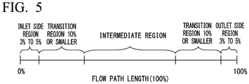
FIG. 5 is a view for describing a dimensional ratio of each region in the impeller according to the embodiment of the present disclosure. - Hereinafter, a centrifugal compressor according to an embodiment of the present disclosure will be described with reference to
FIG. 1 . As shown inFIG. 1 , acentrifugal compressor 1 includes arotary shaft 2, a journal bearing 5, a thrust bearing 6, animpeller 20, and acasing 10. Thecentrifugal compressor 1 of the present embodiment is a so-called uniaxial multi-stage centrifugal compressor including a plurality of stages of theimpellers 20. - The
rotary shaft 2 has a columnar shape extending in a direction of an axis O along a horizontal direction. Therotary shaft 2 is supported to be rotatable around the axis O by the journal bearing 5 on afirst end portion 3 side (other side in the direction of the axis O) and a second end portion 4 side (one side in the direction of the axis O) in the direction of the axis O. In therotary shaft 2, thefirst end portion 3 is supported by the thrust bearing 6. - The plurality of stages of the
impellers 20 are fitted to an outer peripheral surface of therotary shaft 2, and are provided at an interval in the direction of the axis O. Theimpellers 20 rotate around the axis O together with therotary shaft 2 so that gas (fluid) flowing into theimpellers 20 in the direction of the axis O is pumped outward in a radial direction. A detailed configuration of theimpeller 20 will be described later. - The
casing 10 is a member formed in a cylindrical shape, and accommodates therotary shaft 2, theimpeller 20, and the journal bearing 5. Thecasing 10 supports therotary shaft 2 to be rotatable via the journal bearing 5. In this manner, theimpeller 20 attached to therotary shaft 2 can rotate relative to thecasing 10. Thecasing 10 has anintroduction flow path 11, aconnection flow path 13, and adischarge flow path 16. - The
introduction flow path 11 introduces the gas from an outside of thecasing 10 to theimpeller 20 on a forefront stage which is disposed closest to the other side of the plurality ofimpellers 20 in the direction of the axis O. Theintroduction flow path 11 is open on an outer peripheral surface of thecasing 10, and an opening portion thereof is asuction port 12 of the gas. Theintroduction flow path 11 is connected to the other side of theimpeller 20 on the forefront stage in the direction of the axis O in an inner portion in the radial direction. - The
connection flow path 13 is a flow path that connects a pair of theimpellers 20 adjacent to each other in the direction of the axis O. Theconnection flow path 13 introduces the gas discharged outward in the radial direction from theimpeller 20 on a front stage side into theimpeller 20 on a rear stage side from the other side in the direction of the axis O. Theconnection flow path 13 has adiffuser flow path 14 and areturn flow path 15. - The
diffuser flow path 14 is connected to an outside of theimpeller 20 in the radial direction and converts kinematic energy into pressure energy while guiding the gas discharged outward in the radial direction from theimpeller 20 to the outside in the radial direction. Thereturn flow path 15 is connected to the outside of thediffuser flow path 14 in the radial direction, diverts the gas flowing outward in the radial direction to an inside in the radial direction, and guides the gas to theimpeller 20 on the rear stage side. - The
discharge flow path 16 discharges the gas discharged outward in the radial direction from theimpeller 20 on a final stage which is disposed closest to one side of the plurality ofimpellers 20 in the direction of the axis O to the outside of thecasing 10. Thedischarge flow path 16 is open on the outer peripheral surface of thecasing 10, and an opening portion thereof adischarge port 17 of the gas. Thedischarge flow path 16 is connected to the outside in the radial direction of theimpeller 20 on the final stage in an inner portion in the radial direction. - Next, a configuration of the
impeller 20 will be described with reference toFIGS. 2 to 4 . As shown inFIG. 2 , theimpeller 20 has adisc 30, ablade 40, and acover 36. - The
disc 30 is formed in a disc shape around the axis O. Thedisc 30 has a circular shape around the axis O and has a through-hole 31 penetrating in the direction of the axis O. An inner surface of the through-hole 31 is fitted into an outer peripheral surface of therotary shaft 2 such that theimpeller 20 is integrally fixed to therotary shaft 2. - A surface facing the other side in the direction of the axis O in the
disc 30 is a discrear surface 32 having a planar shape orthogonal to the axis O. A disc main surface 33 (main surface) gradually extending outward in the radial direction from the other side toward one side in the axial direction is formed from an end portion on the other side in the direction of the axis O of the through-hole 31 in thedisc 30 to an end portion outside in the radial direction of the discrear surface 32. A portion on the other side in the direction of the axis O in the discmain surface 33 faces outward in the radial direction, and is gradually curved to face the other side in the direction of the axis O toward one side in the direction of the axis O. That is, a diameter of the discmain surface 33 gradually increases toward one side from the other side in the direction of the axis O. The discmain surface 33 has a recessed and curved surface shape. - In the present embodiment, a disc
front end surface 34 having a planar shape orthogonal to the direction of the axis O is formed between an end portion on the other side in the direction of the axis O of the discmain surface 33 and an end portion on one side in the direction of the axis O of the through-hole 31. A discouter end surface 35 extending in the direction of the axis O and serving as an outer peripheral edge portion of thedisc 30 is provided between one end portion in one side in the direction of the axis O of the discmain surface 33 and an end portion outside in the radial direction of the discrear surface 32. - The plurality of
blades 40 are provided at an interval in the circumferential direction of the axis O on the discmain surface 33 in thedisc 30. Each of theblades 40 is curved toward a rear side (one side in the circumferential direction) in a rotation direction of theimpeller 20 from the inside in the radial direction to the outside in the radial direction. Each of theblades 40 extends while forming a projecting and curved surface which projects toward a front side in the rotation direction. - The
cover 36 covers the plurality ofblades 40 from an outer peripheral side. Thecover 36 is provided to face the discmain surface 33 so that theblade 40 is interposed between thedisc 30 and thecover 36. An innerperipheral surface 37 of thecover 36 is formed so that the diameter gradually increases toward one side from the other side in the direction of the axis O. The innerperipheral surface 37 of thecover 36 is curved in the same manner as the discmain surface 33 to correspond to the discmain surface 33. An end portion on a side opposite to the discmain surface 33 side in theblade 40 is fixed to the innerperipheral surface 37 of thecover 36. - The inner
peripheral surface 37 of thecover 36, the discmain surface 33, and the pair ofblades 40 adjacent to each other form a flow path (impeller flow path Fi) therebetween, which extends to be curved to the rear side in the rotational direction from one side toward the other side in the direction of the axis O. - The impeller flow path Fi is divided into a plurality of regions from the
inlet 51 to theoutlet 52. Specifically, the impeller flow path Fi has an inlet side region A1, a transition region A2, an intermediate region A3, a transition region A4, and an outlet side region A5 in this order from theinlet 51 toward theoutlet 52. As shown inFIG. 5 , when a length of the impeller flow path Fi is defined as 100%, the inlet side region A1 is a region of 3% to 5% from theinlet 51 of the impeller flow path Fi. The outlet side region A5 is a region of 3% to 5% from theoutlet 52 of the impeller flow path Fi. The length of the transition regions A2 and A4 is 10% or smaller, when the length of the impeller flow path Fi is defined as 100%. - As shown in
FIG. 3 , in the inlet side region A1 and the outlet side region A5, fillets (small fillet portions 60A) are each formed in a connection portion between theblade 40 and thedisc 30 and a connection portion between theblade 40 and thecover 36. More specifically, thesmall fillet portions 60A are each formed in a portion between the discmain surface 33 and apressure side surface 40A of theblade 40, a portion between the discmain surface 33 and asuction side surface 40B, a portion between the innerperipheral surface 37 of thecover 36 and thepressure side surface 40A of theblade 40, and a portion between the innerperipheral surface 37 of thecover 36 and thesuction side surface 40B. Each of thesmall fillet portions 60A has a curved surface having an arc shape, when viewed in the extending direction of the flow path Fi. A radius of curvature of thesmall fillet portion 60A is preferably as small as possible since the radius of curvature reduces a cross-sectional area of a flow path of a fluid entering the impeller (as described in the front stage). On the other hand, the blade of the impeller which centrifugally compresses the fluid greatly bends a flow direction by applying a large (turning) force to the fluid. Accordingly, in order to relieve stress acting on a joint portion among the blade, the disc, and cover, the fillet having required dimensions is set as the radius of curvature of thesmall fillet portion 60A. An example inFIG. 3 shows a configuration in the respectivesmall fillet portions 60A has mutually the same radius of curvature within the same cross section. However, it is also possible to adopt a configuration in which the radii of curvature are different from each other. - Furthermore, as shown in
FIG. 4 , in the intermediate region A3, fillets (large fillet portions 60B) are each formed in a connection portion between theblade 40 and thedisc 30 and a connection portion between theblade 40 and thecover 36. More specifically, thelarge fillet portions 60B are each formed in a portion between the discmain surface 33 and thepressure side surface 40A of theblade 40, a portion between the discmain surface 33 and thesuction side surface 40B, a portion between the innerperipheral surface 37 of thecover 36 and thepressure side surface 40A of theblade 40, and a portion between the innerperipheral surface 37 of thecover 36 and thesuction side surface 40B. Each of thelarge fillet portions 60B has a curved surface having an arc shape, when viewed in the extending direction of the flow path Fi. It is desirable that the radius of curvature of thelarge fillet portion 60B is set to be relatively larger than the radius of curvature of the above-describedsmall fillet portion 60A. More preferably, the radius of curvature of thelarge fillet portion 60B is 1.2 times to 3 times the radius of curvature of thesmall fillet portion 60A. Most preferably, the radius of curvature of thelarge fillet portion 60B is 1.5 times to 3 times the radius of curvature of thesmall fillet portion 60A. An example inFIG. 4 shows a configuration in which the respectivelarge fillet portions 60B have mutually the same radius of curvature within the same cross section. However, it is also possible to adopt a configuration in which the radii of curvature are different from each other. - Although not shown in detail, other fillets connecting the
small fillet portion 60A and thelarge fillet portion 60B to each other are formed in the transition regions A2 and A4. In the fillets of the transition regions A2 and A4, the radius of curvature gradually increases from thesmall fillet portion 60A toward thelarge fillet portion 60B. In this manner, thesmall fillet portion 60A and thelarge fillet portion 60B are smoothly connected to each other. - Next, an operation of the
centrifugal compressor 1 will be described. When thecentrifugal compressor 1 is driven, therotary shaft 2 is first rotated by an external power source. Theimpeller 20 is integrally rotated in conjunction with the rotation of therotary shaft 2. In this manner, an external fluid is fetched into thecentrifugal compressor 1 through the above-describedintroduction flow path 11. The fluid is compressed as the fluid flows through the flow path between theblades 40 of theimpeller 20, is converted into a high pressure fluid, and flows into theconnection flow path 13. The fluid flowing into theconnection flow path 13 is further compressed by theimpeller 20 in the rear stage. This cycle is repeated until the fluid reaches theimpeller 20 on the final stage, and finally, the fluid having a target pressure is discharged from thedischarge flow path 16. - Incidentally, as described above, in order to relieve stress concentration, fillets are formed in the connection portion between the
blade 40 and thedisc 30 and the connection portion between theblade 40 and thecover 36. In general, the radius of curvature of the fillet is constant over an entire region of the flow path. Here, in the impeller flow path Fi, particularly in the inlet side region A1, the cross-sectional area of the flow path is suddenly changed (decreases) due to a leading edge portion of the blade with respect to the flow path on the front stage side forming an annular space. Accordingly, the flow in the impeller flow path Fi may be disturbed in some cases. In addition, the above-described fillet is thicker than theblade 40. Accordingly, there is a possibility that the disturbance such as flow separation may start from the fillet. In this way, in order to suppress the influence on the flow, that is, a loss, it is desirable that the fillet is small. However, in order to relieve the stress concentration acting on the connection portion among the blade, the disc, and the cover, the fillet needs to have a corresponding size. That is, in order to secure strength while avoiding the loss in the impeller flow path, a size and a shape of the fillet need two contradictory requirements. - Therefore, in the present embodiment, the
small fillet portion 60A is formed in at least one of the inlet side region A1 and the outlet side region A5, and thelarge fillet portion 60B is formed in the intermediate region A3. According to this configuration, a behavior of the fluid is optimized in the inlet side region A1 and the outlet side region A5, and performance as theimpeller 20 can be improved. On the other hand, in the intermediate region A3, thecover 36 needs to be supported by theblade 40. Therefore, higher strength is required than that in the inlet side region A1 and the outlet side region A5. In the above-described configuration, thelarge fillet portion 60B having a large radius of curvature is formed in the intermediate region A3. Therefore, strength in the intermediate region A3 can be improved. - Here, in the one-piece type impeller in which the
disc 30, theblade 40, and thecover 36 are integrally formed, a tool is caused to reach the inside from theinlet 51 side or theoutlet 52 side of the impeller flow path Fi during a manufacturing process. In this manner, the flow path is formed by carrying out cutting work. When the fillet in the intermediate region is the large fillet, the amount of the cutting work decreases. Therefore, the configuration leads to a decrease in man-hours or times required for manufacturing theimpeller 20. - According to the above-described configuration, the transition regions A2 and A4 are formed between the
small fillet portion 60A and thelarge fillet portion 60B. In the transition regions A2 and A4, the radius of curvature gradually increases from thesmall fillet portion 60A toward thelarge fillet portion 60B. Therefore, the fluid can smoothly flow without causing a disturbance or a vortex in the flow of the fluid. In this manner, the performance of the impeller can be further improved. - Hitherto, the embodiment of the present disclosure has been described in detail with reference to the drawings. However, a specific configuration is not limited to the embodiment, and the present disclosure also includes a design change within the scope not departing from the concept of the present disclosure.
- For example, the above-described
impeller 20 is suitably applicable not only to thecentrifugal compressor 1 but also to a centrifugal pump for pumping a liquid. - In addition, in the above-described embodiment, an example has been described in which the
small fillet portions 60A are each formed in both the inlet side region A1 and the outlet side region A5. However, thesmall fillet portion 60A can be formed only in the inlet side region A1 or only in the outlet side region A5. In order to improve the performance of theimpeller 20, it is particularly desirable to form thesmall fillet portion 60A in the inlet side region A1. - The
impeller 20 and thecentrifugal compressor 1 which are described in each embodiment can be recognized as follows, for example. - (1) According to a first aspect, there is provided the
impeller 20 including thedisc 30 rotatable around the axis O, and having the main surface (disc main surface 33) extending outward in the radial direction toward one side in the direction of the axis O, the plurality ofblades 40 disposed on the main surface at an interval in the circumferential direction, and defining the flow path (impeller flow path Fi) extending to theoutlet 52 on one side from theinlet 51 on the other side in the direction of the axis O, and thecover 36 disposed to face the main surface and to cover the plurality ofblades 40. At least one of the inlet side region A1 including the end portion on theinlet 51 side and the outlet side region A5 including the end portion on theoutlet 52 side which are the connection portion between theblade 40 and the main surface and the connection portion between theblade 40 and thecover 36 has thesmall fillet portion 60A curved in the arc shape and having the relatively small radius of curvature when viewed in the extending direction of theblade 40. The intermediate region A3 formed between the inlet side region A1 and the outlet side region A5 which are the connection portion between theblade 40 and the main surface and the connection portion between theblade 40 and the cover has thelarge fillet portion 60B curved in the arc shape and having the relatively large radius of curvature when viewed in the extending direction of theblade 40. - According to the above-described configuration, the
small fillet portion 60A having the relatively small radius of curvature is formed in at least one of the inlet side region A1 and the outlet side region A5. Furthermore, thelarge fillet portion 60B having the relatively large radius of curvature is formed in the intermediate region A3 between the inlet side region A1 and the outlet side region A5. In this manner, the behavior of the fluid is optimized in at least one of the inlet side region A1 and the outlet side region A5, and the performance as theimpeller 20 can be improved. On the other hand, in the intermediate region A3, thecover 36 needs to be supported by theblade 40. Therefore, higher strength is required than that in the inlet side region A1 and the outlet side region A5. In the above-described configuration, thelarge fillet portion 60B having the large radius of curvature is formed in the intermediate region A3. Therefore, for example, a plate thickness is thicker than that when the radius of curvature is small. In this manner, the strength in the intermediate region A3 can be improved. - Incidentally, in the one-
piece type impeller 20 in which thedisc 30, theblade 40, and thecover 36 are integrally formed, the tool is caused to reach the inside from theinlet 51 side or theoutlet 52 side of the flow path during the manufacturing process. In this manner, the above-describedsmall fillet portion 60A is formed by carrying out cutting work. On the other hand, as described above, only thelarge fillet portion 60B is formed in the intermediate region A3. Therefore, in thelarge fillet portion 60B, it is not necessary to reduce the radius of curvature by carrying out the work, or the amount of the work can be minimized. As a result, it is possible to decrease the man-hours or the times required for manufacturing the impeller. - (2) According to a second aspect, the
impeller 20 may further include the transition regions A2 and A4 formed in at least one of the portion between the inlet side region A1 and the intermediate region A3 and the portion between the outlet side region A5 and the intermediate region A3, and having the radius of curvature which gradually increases from thesmall fillet portion 60A toward thelarge fillet portion 60B. - According to the above-described configuration, the transition regions A2 and A4 are formed between the
small fillet portion 60A and thelarge fillet portion 60B. In the transition regions A2 and A4, the radius of curvature gradually increases from thesmall fillet portion 60A toward thelarge fillet portion 60B. Therefore, the fluid can smoothly flow without causing a disturbance or a vortex in the flow of the fluid. In this manner, the performance of theimpeller 20 can be further improved. - (3) According to a third aspect, in the
impeller 20, the length of the inlet side region A1 and the outlet side region A5 is 3% to 5% when the length of the flow path is defined as 100%. - According to the above-described configuration, the behavior of the fluid in the inlet side region A1 and the outlet side region A5 is optimized, and the performance as the
impeller 20 can be further improved. In addition, the region requiring work for forming thesmall fillet portion 60A can be minimized. Therefore, theimpeller 20 can be more easily manufactured in a shorter period of time. - (4) According to a fourth aspect, in the
impeller 20, the length of the transition regions A2 and A4 is 10% or smaller when the length of the flow path is defined as 100%. - According to the above-described configuration, the length of the transition regions A2 and A4 is sufficiently secured. Therefore, the fluid can smoothly flow without causing the disturbance or the vortex in the flow of the fluid. In this manner, the performance of the
impeller 20 can be further improved. - (5) According to a fifth aspect, in the
impeller 20, the radius of curvature of thelarge fillet portion 60B is 1.2 times to 3 times the radius of curvature of thesmall fillet portion 60A. - According to the above-described configuration, the performance of the
impeller 20 can be further improved. - (6) According to a sixth aspect, there is provided the
centrifugal compressor 1 including therotary shaft 2 extending along the axis O, theimpeller 20 fixed to therotary shaft 2 according to any one of the above-described aspects, and thecasing 10 that covers therotary shaft 2 and theimpeller 20 from the outer peripheral side. - According to the above-described configuration, it is possible to provide the
centrifugal compressor 1 which can be more stably operated by improving both the performance and the strength of theimpeller 20. - While preferred embodiments of the invention have been described and shown above, it should be understood that these are exemplary of the invention and are not to be considered as limiting. Additions, omissions, substitutions, and other modifications can be made without departing from the spirit or scope of the present invention. Accordingly, the invention is not to be considered as being limited by the foregoing description, and is only limited by the scope of the appended claims.
-
- 1 centrifugal compressor
- 2 rotary shaft
- 3 first end portion
- 4 second end portion
- 5 journal bearing
- 6 thrust bearing
- 10 casing
- 11 introduction flow path
- 12 suction port
- 13 connection flow path
- 14 diffuser flow path
- 15 return flow path
- 16 discharge flow path
- 17 discharge port
- 20 impeller
- 30 disc
- 31 through-hole
- 32 disc rear surface
- 33 disc main surface
- 34 disc front end surface
- 35 disc outer end surface
- 36 cover
- 37 inner peripheral surface
- 40 blade
- 40A pressure side surface
- 40B suction side surface
- 51 inlet
- 52 outlet
- 60A small fillet portion
- 60B large fillet portion
- A1 inlet side region
- A2 transition region
- A3 intermediate region
- A4 transition region
- A5 outlet side region
- Fi impeller flow path (flow path)
- O axis
Claims (6)
- An impeller comprising:a disc rotatable around an axis, the disc having a main surface extending outward in a radial direction toward one side in an axial direction;a plurality of blades disposed on the main surface at an interval in a circumferential direction, and defining a flow path extending to an outlet on one side from an inlet on the other side in the axial direction; anda cover disposed to face the main surface to cover the plurality of blades,wherein at least one of an inlet side region including an end portion on the inlet side and an outlet side region including an end portion on the outlet side has a small fillet portion curved in an arc shape and having a relatively small radius of curvature when viewed in an extending direction of the blade at a connection portion between the blade and the main surface and a connection portion between the blade and the cover, andan intermediate region formed between the inlet side region and the outlet side region has a large fillet portion curved in an arc shape and having a relatively large radius of curvature when viewed in the extending direction of the blade at the connection portion between the blade and the main surface and the connection portion between the blade and the cover.
- The impeller according to claim 1, further comprising:a transition region formed in at least one of a portion between the inlet side region and the intermediate region and a portion between the outlet side region and the intermediate region, and having the radius of curvature which gradually increases from the small fillet portion toward the large fillet portion.
- The impeller according to claim 1 or 2,
wherein a length of the inlet side region and the outlet side region is 3% to 5% when a length of the flow path is defined as 100%. - The impeller according to claim 2,
wherein a length of the transition region is 10% or smaller when a length of the flow path is defined as 100%. - The impeller according to any one of claims 1 to 4,
wherein the radius of curvature of the large fillet portion is 1.2 times to 3 times the radius of curvature of the small fillet portion. - A centrifugal compressor comprising:a rotary shaft extending along an axis;the impeller according to any one of claims 1 to 5, which is fixed to the rotary shaft; anda casing that covers the rotary shaft and the impeller from an outer peripheral side.
Applications Claiming Priority (1)
| Application Number | Priority Date | Filing Date | Title |
|---|---|---|---|
| JP2020058251A JP7591871B2 (en) | 2020-03-27 | 2020-03-27 | Impeller for centrifugal compressor, and centrifugal compressor |
Publications (2)
| Publication Number | Publication Date |
|---|---|
| EP3885580A1 true EP3885580A1 (en) | 2021-09-29 |
| EP3885580B1 EP3885580B1 (en) | 2024-11-20 |
Family
ID=74859827
Family Applications (1)
| Application Number | Title | Priority Date | Filing Date |
|---|---|---|---|
| EP21161325.2A Active EP3885580B1 (en) | 2020-03-27 | 2021-03-08 | Impeller and centrifugal compressor |
Country Status (4)
| Country | Link |
|---|---|
| US (1) | US11401944B2 (en) |
| EP (1) | EP3885580B1 (en) |
| JP (1) | JP7591871B2 (en) |
| CN (1) | CN113446260B (en) |
Families Citing this family (3)
| Publication number | Priority date | Publication date | Assignee | Title |
|---|---|---|---|---|
| JP7767961B2 (en) * | 2022-02-08 | 2025-11-12 | 株式会社デンソー | centrifugal blower |
| EP4534852A1 (en) * | 2023-10-03 | 2025-04-09 | Honeywell International Inc. | Axially nested compressors |
| US12129859B1 (en) * | 2023-10-03 | 2024-10-29 | Honeywell International Inc. | Axially nested compressors |
Citations (5)
| Publication number | Priority date | Publication date | Assignee | Title |
|---|---|---|---|---|
| JPS6088898A (en) * | 1983-10-19 | 1985-05-18 | Sanyo Electric Co Ltd | Centrifugal fan |
| JP2012177320A (en) * | 2011-02-25 | 2012-09-13 | Mitsubishi Heavy Ind Ltd | Rotary machine |
| US9163642B2 (en) * | 2009-07-13 | 2015-10-20 | Mitsubishi Heavy Industries, Ltd. | Impeller and rotary machine |
| WO2018042653A1 (en) | 2016-09-05 | 2018-03-08 | 三菱重工コンプレッサ株式会社 | Method for manufacturing centrifugal rotary machine and method for manufacturing impeller therefor |
| JP2020058251A (en) | 2018-10-05 | 2020-04-16 | 株式会社クボタ | Combine-harvester |
Family Cites Families (8)
| Publication number | Priority date | Publication date | Assignee | Title |
|---|---|---|---|---|
| JPH08159088A (en) * | 1994-12-06 | 1996-06-18 | Ishikawajima Harima Heavy Ind Co Ltd | Impeller manufacturing method |
| US5735672A (en) * | 1996-09-16 | 1998-04-07 | Delaware Capital Formation, Inc. | Centrifugal compressor impeller |
| JP2001234885A (en) * | 2001-01-17 | 2001-08-31 | Hitachi Ltd | Multistage centrifugal compressor and impeller for multistage centrifugal compressor |
| CN101769266B (en) * | 2010-03-23 | 2011-08-31 | 上海交通大学 | Centrifugal fan blade |
| CN102011752B (en) * | 2010-12-20 | 2012-10-24 | 山东大学 | Manufacturing process of variable-curvature profile and cambered front-disk multi-blade centrifugal fan impeller |
| KR102208490B1 (en) * | 2014-07-07 | 2021-01-27 | 한화에어로스페이스 주식회사 | Method for manufacturing rotation part of rotary machine |
| US20160245297A1 (en) * | 2015-02-23 | 2016-08-25 | Howden Roots Llc | Impeller comprising variably-dimensioned fillet to secure blades and compressor comprised thereof |
| FI3440360T3 (en) * | 2016-04-06 | 2023-09-26 | Smidth As F L | A low inlet vortex impeller with improved hydrodynamic wear characteristics |
-
2020
- 2020-03-27 JP JP2020058251A patent/JP7591871B2/en active Active
-
2021
- 2021-03-02 US US17/189,660 patent/US11401944B2/en active Active
- 2021-03-08 EP EP21161325.2A patent/EP3885580B1/en active Active
- 2021-03-23 CN CN202110310561.1A patent/CN113446260B/en active Active
Patent Citations (5)
| Publication number | Priority date | Publication date | Assignee | Title |
|---|---|---|---|---|
| JPS6088898A (en) * | 1983-10-19 | 1985-05-18 | Sanyo Electric Co Ltd | Centrifugal fan |
| US9163642B2 (en) * | 2009-07-13 | 2015-10-20 | Mitsubishi Heavy Industries, Ltd. | Impeller and rotary machine |
| JP2012177320A (en) * | 2011-02-25 | 2012-09-13 | Mitsubishi Heavy Ind Ltd | Rotary machine |
| WO2018042653A1 (en) | 2016-09-05 | 2018-03-08 | 三菱重工コンプレッサ株式会社 | Method for manufacturing centrifugal rotary machine and method for manufacturing impeller therefor |
| JP2020058251A (en) | 2018-10-05 | 2020-04-16 | 株式会社クボタ | Combine-harvester |
Also Published As
| Publication number | Publication date |
|---|---|
| CN113446260A (en) | 2021-09-28 |
| CN113446260B (en) | 2023-11-21 |
| JP2021156223A (en) | 2021-10-07 |
| US11401944B2 (en) | 2022-08-02 |
| US20210301831A1 (en) | 2021-09-30 |
| JP7591871B2 (en) | 2024-11-29 |
| EP3885580B1 (en) | 2024-11-20 |
Similar Documents
| Publication | Publication Date | Title |
|---|---|---|
| US11401944B2 (en) | Impeller and centrifugal compressor | |
| CN104105886B (en) | Rotary machine | |
| US10400790B2 (en) | Compressor | |
| CN102365463A (en) | Impeller and rotary machine | |
| CN108869397B (en) | Volute for centrifugal pump and centrifugal pump | |
| US10947988B2 (en) | Impeller and centrifugal compressor | |
| EP3421814B1 (en) | Centrifugal compressor | |
| EP3421815B1 (en) | Centrifugal compressor | |
| EP3587828A1 (en) | Centrifugal compressor and turbo refrigerator | |
| EP3561312A1 (en) | Centrifugal compressor | |
| EP3096022A1 (en) | Impeller and rotating machine provided with same | |
| EP3702624B1 (en) | Impeller and rotating machine | |
| CN110869616A (en) | Multi-stage pump with enhanced thrust balancing features | |
| US11873822B2 (en) | Centrifugal compressor | |
| JP2024086911A (en) | Impeller and centrifugal compressor | |
| EP3770442A1 (en) | Centrifugal compressor | |
| EP3828417B1 (en) | Bridged stage piece | |
| EP3196479A1 (en) | Centrifugal compressor | |
| EP3839263A1 (en) | Shrouded impeller with shroud reinforcing struts in the impeller suction eye | |
| JP2004197738A (en) | Advanced diffuser for centrifugal compressor |
Legal Events
| Date | Code | Title | Description |
|---|---|---|---|
| PUAI | Public reference made under article 153(3) epc to a published international application that has entered the european phase |
Free format text: ORIGINAL CODE: 0009012 |
|
| STAA | Information on the status of an ep patent application or granted ep patent |
Free format text: STATUS: THE APPLICATION HAS BEEN PUBLISHED |
|
| AK | Designated contracting states |
Kind code of ref document: A1 Designated state(s): AL AT BE BG CH CY CZ DE DK EE ES FI FR GB GR HR HU IE IS IT LI LT LU LV MC MK MT NL NO PL PT RO RS SE SI SK SM TR |
|
| STAA | Information on the status of an ep patent application or granted ep patent |
Free format text: STATUS: REQUEST FOR EXAMINATION WAS MADE |
|
| 17P | Request for examination filed |
Effective date: 20220215 |
|
| RBV | Designated contracting states (corrected) |
Designated state(s): AL AT BE BG CH CY CZ DE DK EE ES FI FR GB GR HR HU IE IS IT LI LT LU LV MC MK MT NL NO PL PT RO RS SE SI SK SM TR |
|
| STAA | Information on the status of an ep patent application or granted ep patent |
Free format text: STATUS: EXAMINATION IS IN PROGRESS |
|
| 17Q | First examination report despatched |
Effective date: 20230215 |
|
| GRAP | Despatch of communication of intention to grant a patent |
Free format text: ORIGINAL CODE: EPIDOSNIGR1 |
|
| STAA | Information on the status of an ep patent application or granted ep patent |
Free format text: STATUS: GRANT OF PATENT IS INTENDED |
|
| INTG | Intention to grant announced |
Effective date: 20240618 |
|
| GRAS | Grant fee paid |
Free format text: ORIGINAL CODE: EPIDOSNIGR3 |
|
| GRAA | (expected) grant |
Free format text: ORIGINAL CODE: 0009210 |
|
| STAA | Information on the status of an ep patent application or granted ep patent |
Free format text: STATUS: THE PATENT HAS BEEN GRANTED |
|
| AK | Designated contracting states |
Kind code of ref document: B1 Designated state(s): AL AT BE BG CH CY CZ DE DK EE ES FI FR GB GR HR HU IE IS IT LI LT LU LV MC MK MT NL NO PL PT RO RS SE SI SK SM TR |
|
| REG | Reference to a national code |
Ref country code: GB Ref legal event code: FG4D |
|
| REG | Reference to a national code |
Ref country code: CH Ref legal event code: EP |
|
| REG | Reference to a national code |
Ref country code: DE Ref legal event code: R096 Ref document number: 602021021962 Country of ref document: DE |
|
| REG | Reference to a national code |
Ref country code: IE Ref legal event code: FG4D |
|
| RAP4 | Party data changed (patent owner data changed or rights of a patent transferred) |
Owner name: MITSUBISHI HEAVY INDUSTRIES COMPRESSOR CORPORATION |
|
| REG | Reference to a national code |
Ref country code: LT Ref legal event code: MG9D |
|
| REG | Reference to a national code |
Ref country code: NL Ref legal event code: MP Effective date: 20241120 |
|
| PG25 | Lapsed in a contracting state [announced via postgrant information from national office to epo] |
Ref country code: PT Free format text: LAPSE BECAUSE OF FAILURE TO SUBMIT A TRANSLATION OF THE DESCRIPTION OR TO PAY THE FEE WITHIN THE PRESCRIBED TIME-LIMIT Effective date: 20250320 Ref country code: HR Free format text: LAPSE BECAUSE OF FAILURE TO SUBMIT A TRANSLATION OF THE DESCRIPTION OR TO PAY THE FEE WITHIN THE PRESCRIBED TIME-LIMIT Effective date: 20241120 Ref country code: IS Free format text: LAPSE BECAUSE OF FAILURE TO SUBMIT A TRANSLATION OF THE DESCRIPTION OR TO PAY THE FEE WITHIN THE PRESCRIBED TIME-LIMIT Effective date: 20250320 |
|
| PG25 | Lapsed in a contracting state [announced via postgrant information from national office to epo] |
Ref country code: NL Free format text: LAPSE BECAUSE OF FAILURE TO SUBMIT A TRANSLATION OF THE DESCRIPTION OR TO PAY THE FEE WITHIN THE PRESCRIBED TIME-LIMIT Effective date: 20241120 Ref country code: FI Free format text: LAPSE BECAUSE OF FAILURE TO SUBMIT A TRANSLATION OF THE DESCRIPTION OR TO PAY THE FEE WITHIN THE PRESCRIBED TIME-LIMIT Effective date: 20241120 |
|
| REG | Reference to a national code |
Ref country code: AT Ref legal event code: MK05 Ref document number: 1743811 Country of ref document: AT Kind code of ref document: T Effective date: 20241120 |
|
| PG25 | Lapsed in a contracting state [announced via postgrant information from national office to epo] |
Ref country code: BG Free format text: LAPSE BECAUSE OF FAILURE TO SUBMIT A TRANSLATION OF THE DESCRIPTION OR TO PAY THE FEE WITHIN THE PRESCRIBED TIME-LIMIT Effective date: 20241120 |
|
| PG25 | Lapsed in a contracting state [announced via postgrant information from national office to epo] |
Ref country code: ES Free format text: LAPSE BECAUSE OF FAILURE TO SUBMIT A TRANSLATION OF THE DESCRIPTION OR TO PAY THE FEE WITHIN THE PRESCRIBED TIME-LIMIT Effective date: 20241120 |
|
| PG25 | Lapsed in a contracting state [announced via postgrant information from national office to epo] |
Ref country code: NO Free format text: LAPSE BECAUSE OF FAILURE TO SUBMIT A TRANSLATION OF THE DESCRIPTION OR TO PAY THE FEE WITHIN THE PRESCRIBED TIME-LIMIT Effective date: 20250220 |
|
| PG25 | Lapsed in a contracting state [announced via postgrant information from national office to epo] |
Ref country code: LV Free format text: LAPSE BECAUSE OF FAILURE TO SUBMIT A TRANSLATION OF THE DESCRIPTION OR TO PAY THE FEE WITHIN THE PRESCRIBED TIME-LIMIT Effective date: 20241120 Ref country code: GR Free format text: LAPSE BECAUSE OF FAILURE TO SUBMIT A TRANSLATION OF THE DESCRIPTION OR TO PAY THE FEE WITHIN THE PRESCRIBED TIME-LIMIT Effective date: 20250221 Ref country code: AT Free format text: LAPSE BECAUSE OF FAILURE TO SUBMIT A TRANSLATION OF THE DESCRIPTION OR TO PAY THE FEE WITHIN THE PRESCRIBED TIME-LIMIT Effective date: 20241120 |
|
| PG25 | Lapsed in a contracting state [announced via postgrant information from national office to epo] |
Ref country code: PL Free format text: LAPSE BECAUSE OF FAILURE TO SUBMIT A TRANSLATION OF THE DESCRIPTION OR TO PAY THE FEE WITHIN THE PRESCRIBED TIME-LIMIT Effective date: 20241120 |
|
| PG25 | Lapsed in a contracting state [announced via postgrant information from national office to epo] |
Ref country code: RS Free format text: LAPSE BECAUSE OF FAILURE TO SUBMIT A TRANSLATION OF THE DESCRIPTION OR TO PAY THE FEE WITHIN THE PRESCRIBED TIME-LIMIT Effective date: 20250220 |
|
| PG25 | Lapsed in a contracting state [announced via postgrant information from national office to epo] |
Ref country code: SM Free format text: LAPSE BECAUSE OF FAILURE TO SUBMIT A TRANSLATION OF THE DESCRIPTION OR TO PAY THE FEE WITHIN THE PRESCRIBED TIME-LIMIT Effective date: 20241120 |
|
| PG25 | Lapsed in a contracting state [announced via postgrant information from national office to epo] |
Ref country code: DK Free format text: LAPSE BECAUSE OF FAILURE TO SUBMIT A TRANSLATION OF THE DESCRIPTION OR TO PAY THE FEE WITHIN THE PRESCRIBED TIME-LIMIT Effective date: 20241120 |
|
| PG25 | Lapsed in a contracting state [announced via postgrant information from national office to epo] |
Ref country code: EE Free format text: LAPSE BECAUSE OF FAILURE TO SUBMIT A TRANSLATION OF THE DESCRIPTION OR TO PAY THE FEE WITHIN THE PRESCRIBED TIME-LIMIT Effective date: 20241120 |
|
| PG25 | Lapsed in a contracting state [announced via postgrant information from national office to epo] |
Ref country code: RO Free format text: LAPSE BECAUSE OF FAILURE TO SUBMIT A TRANSLATION OF THE DESCRIPTION OR TO PAY THE FEE WITHIN THE PRESCRIBED TIME-LIMIT Effective date: 20241120 |
|
| PG25 | Lapsed in a contracting state [announced via postgrant information from national office to epo] |
Ref country code: SK Free format text: LAPSE BECAUSE OF FAILURE TO SUBMIT A TRANSLATION OF THE DESCRIPTION OR TO PAY THE FEE WITHIN THE PRESCRIBED TIME-LIMIT Effective date: 20241120 |
|
| PG25 | Lapsed in a contracting state [announced via postgrant information from national office to epo] |
Ref country code: CZ Free format text: LAPSE BECAUSE OF FAILURE TO SUBMIT A TRANSLATION OF THE DESCRIPTION OR TO PAY THE FEE WITHIN THE PRESCRIBED TIME-LIMIT Effective date: 20241120 |
|
| REG | Reference to a national code |
Ref country code: DE Ref legal event code: R097 Ref document number: 602021021962 Country of ref document: DE |
|
| PG25 | Lapsed in a contracting state [announced via postgrant information from national office to epo] |
Ref country code: SE Free format text: LAPSE BECAUSE OF FAILURE TO SUBMIT A TRANSLATION OF THE DESCRIPTION OR TO PAY THE FEE WITHIN THE PRESCRIBED TIME-LIMIT Effective date: 20241120 |
|
| PLBE | No opposition filed within time limit |
Free format text: ORIGINAL CODE: 0009261 |
|
| STAA | Information on the status of an ep patent application or granted ep patent |
Free format text: STATUS: NO OPPOSITION FILED WITHIN TIME LIMIT |
|
| PG25 | Lapsed in a contracting state [announced via postgrant information from national office to epo] |
Ref country code: MC Free format text: LAPSE BECAUSE OF FAILURE TO SUBMIT A TRANSLATION OF THE DESCRIPTION OR TO PAY THE FEE WITHIN THE PRESCRIBED TIME-LIMIT Effective date: 20241120 |
|
| 26N | No opposition filed |
Effective date: 20250821 |
|
| REG | Reference to a national code |
Ref country code: CH Ref legal event code: H13 Free format text: ST27 STATUS EVENT CODE: U-0-0-H10-H13 (AS PROVIDED BY THE NATIONAL OFFICE) Effective date: 20251023 |
|
| PG25 | Lapsed in a contracting state [announced via postgrant information from national office to epo] |
Ref country code: LU Free format text: LAPSE BECAUSE OF NON-PAYMENT OF DUE FEES Effective date: 20250308 |
|
| GBPC | Gb: european patent ceased through non-payment of renewal fee |
Effective date: 20250308 |
|
| REG | Reference to a national code |
Ref country code: BE Ref legal event code: MM Effective date: 20250331 |
|
| PG25 | Lapsed in a contracting state [announced via postgrant information from national office to epo] |
Ref country code: GB Free format text: LAPSE BECAUSE OF NON-PAYMENT OF DUE FEES Effective date: 20250308 |
|
| PG25 | Lapsed in a contracting state [announced via postgrant information from national office to epo] |
Ref country code: FR Free format text: LAPSE BECAUSE OF NON-PAYMENT OF DUE FEES Effective date: 20250331 |
|
| PG25 | Lapsed in a contracting state [announced via postgrant information from national office to epo] |
Ref country code: BE Free format text: LAPSE BECAUSE OF NON-PAYMENT OF DUE FEES Effective date: 20250331 |
|
| PG25 | Lapsed in a contracting state [announced via postgrant information from national office to epo] |
Ref country code: CH Free format text: LAPSE BECAUSE OF NON-PAYMENT OF DUE FEES Effective date: 20250331 |
|
| PG25 | Lapsed in a contracting state [announced via postgrant information from national office to epo] |
Ref country code: IE Free format text: LAPSE BECAUSE OF NON-PAYMENT OF DUE FEES Effective date: 20250308 |
|
| PGFP | Annual fee paid to national office [announced via postgrant information from national office to epo] |
Ref country code: DE Payment date: 20260128 Year of fee payment: 6 |
|
| PGFP | Annual fee paid to national office [announced via postgrant information from national office to epo] |
Ref country code: IT Payment date: 20260220 Year of fee payment: 6 |