EP3885252A1 - Wing and aircraft - Google Patents
Wing and aircraft Download PDFInfo
- Publication number
- EP3885252A1 EP3885252A1 EP21153790.7A EP21153790A EP3885252A1 EP 3885252 A1 EP3885252 A1 EP 3885252A1 EP 21153790 A EP21153790 A EP 21153790A EP 3885252 A1 EP3885252 A1 EP 3885252A1
- Authority
- EP
- European Patent Office
- Prior art keywords
- blade
- flow path
- fan
- leading edge
- housing section
- Prior art date
- Legal status (The legal status is an assumption and is not a legal conclusion. Google has not performed a legal analysis and makes no representation as to the accuracy of the status listed.)
- Withdrawn
Links
Images




Classifications
-
- B—PERFORMING OPERATIONS; TRANSPORTING
- B64—AIRCRAFT; AVIATION; COSMONAUTICS
- B64C—AEROPLANES; HELICOPTERS
- B64C11/00—Propellers, e.g. of ducted type; Features common to propellers and rotors for rotorcraft
- B64C11/001—Shrouded propellers
-
- B—PERFORMING OPERATIONS; TRANSPORTING
- B64—AIRCRAFT; AVIATION; COSMONAUTICS
- B64C—AEROPLANES; HELICOPTERS
- B64C27/00—Rotorcraft; Rotors peculiar thereto
- B64C27/22—Compound rotorcraft, i.e. aircraft using in flight the features of both aeroplane and rotorcraft
- B64C27/26—Compound rotorcraft, i.e. aircraft using in flight the features of both aeroplane and rotorcraft characterised by provision of fixed wings
-
- B—PERFORMING OPERATIONS; TRANSPORTING
- B64—AIRCRAFT; AVIATION; COSMONAUTICS
- B64C—AEROPLANES; HELICOPTERS
- B64C21/00—Influencing air flow over aircraft surfaces by affecting boundary layer flow
-
- B—PERFORMING OPERATIONS; TRANSPORTING
- B64—AIRCRAFT; AVIATION; COSMONAUTICS
- B64C—AEROPLANES; HELICOPTERS
- B64C23/00—Influencing air flow over aircraft surfaces, not otherwise provided for
- B64C23/005—Influencing air flow over aircraft surfaces, not otherwise provided for by other means not covered by groups B64C23/02 - B64C23/08, e.g. by electric charges, magnetic panels, piezoelectric elements, static charges or ultrasounds
-
- B—PERFORMING OPERATIONS; TRANSPORTING
- B64—AIRCRAFT; AVIATION; COSMONAUTICS
- B64C—AEROPLANES; HELICOPTERS
- B64C29/00—Aircraft capable of landing or taking-off vertically, e.g. vertical take-off and landing [VTOL] aircraft
- B64C29/0008—Aircraft capable of landing or taking-off vertically, e.g. vertical take-off and landing [VTOL] aircraft having its flight directional axis horizontal when grounded
- B64C29/0016—Aircraft capable of landing or taking-off vertically, e.g. vertical take-off and landing [VTOL] aircraft having its flight directional axis horizontal when grounded the lift during taking-off being created by free or ducted propellers or by blowers
- B64C29/0025—Aircraft capable of landing or taking-off vertically, e.g. vertical take-off and landing [VTOL] aircraft having its flight directional axis horizontal when grounded the lift during taking-off being created by free or ducted propellers or by blowers the propellers being fixed relative to the fuselage
-
- B—PERFORMING OPERATIONS; TRANSPORTING
- B64—AIRCRAFT; AVIATION; COSMONAUTICS
- B64C—AEROPLANES; HELICOPTERS
- B64C3/00—Wings
- B64C3/10—Shape of wings
- B64C3/14—Aerofoil profile
-
- B—PERFORMING OPERATIONS; TRANSPORTING
- B64—AIRCRAFT; AVIATION; COSMONAUTICS
- B64C—AEROPLANES; HELICOPTERS
- B64C3/00—Wings
- B64C3/10—Shape of wings
- B64C3/14—Aerofoil profile
- B64C2003/143—Aerofoil profile comprising interior channels
Definitions
- the present disclosure relates to a blade and an aircraft.
- VTOL vertical take-off & landing
- the type of airframe used in an electric VTOL aircraft varies depending on requirements such as cruise speed, cruise range, and payload. For example, in a case where a fast cruise speed or a long cruise range is required, a tiltwing aircraft or a tiltrotor aircraft having a main wing is often employed.
- Patent Literature 1 US 2019/0,291,860 A
- the lift fan and the thrust fan are mounted separately, only the thrust fan is used while cruising, which is the period not including takeoff and landing, and thus, the lift fan acts as a drag element that inhibits the flow of air.
- Patent Literature 1 even in a configuration in which the thrust fan is provided at the trailing edge of the main wing and the lift fan is housed inside the main wing, the space in which the lift fan is housed causes a blade upper surface and a blade lower surface to communicate with each other and allow air to pass through, and there is a possibility that the performance as a blade deteriorates.
- Patent Literature 1 also discloses a louver that covers the housing space of the lift fan, but the louver and a mechanism for opening and closing the louver increase the weight of the airframe. As a result, there is a problem such as increase in power consumption or deterioration of flight stability.
- an object of the present disclosure is to provide a blade and an aircraft capable of preventing the passage of air between a blade upper surface and a blade lower surface without increasing weight, to thereby suppress deterioration of performance of the blade body.
- the blade and the aircraft of the present disclosure adopt the following technique.
- a blade including: a blade body configured to include a housing section that penetrates in a blade thickness direction between a leading edge and a trailing edge; a lift fan that is provided inside the housing section and is configured to generate an airflow in the blade thickness direction; and a thrust fan that is provided at the leading edge of the blade body and is configured to generate an airflow from the leading edge toward the trailing edge on a blade upper surface and a blade lower surface of the blade body.
- an aircraft according to another aspect of the present disclosure includes the above-described blade.
- the blade and the aircraft of the present disclosure it is possible to prevent the passage of air between the blade upper surface and the blade lower surface without increasing weight, and suppress deterioration of performance of the blade body.
- FIG. 1 is a perspective view of an aircraft 1 including the blades 10.
- FIG. 2 is a cross-sectional view of the blade 10 along the line II-II of FIG. 1 .
- FIG. 3 is a plan view of the blade 10 viewed from the arrow A illustrated in FIG. 1 .
- the aircraft 1 is a VTOL aircraft (a so-called compound aircraft) with an airframe in which a lift fan and a thrust fan are separately mounted.
- Each blade 10 is preferably employed in the blade structure of the aircraft 1.
- a case where one lift fan 40 is provided on one of the blades 10 will be described as an example.
- a plurality of lift fans 40 may be provided along the chord direction.
- each blade 10 includes a blade body 20, the lift fan 40, and a thrust fan 50.
- the blade body 20 is a known blade type in which the blade thickness changes from a leading edge 22a toward a trailing edge 22b.
- a housing section 21 is formed between the leading edge 22a and the trailing edge 22b.
- the housing section 21 is a space that penetrates from a blade upper surface 23a to a blade lower surface 23b in the blade thickness direction. As illustrated in FIG. 3 , the housing section 21 is a cylindrical space. As illustrated in FIGS. 2 and 3 , the lift fan 40 is housed in the housing section 21.
- the lift fan 40 is a fan that rotates about an axis XL and generates an airflow in the blade thickness direction.
- the lift fan 40 is mainly used for takeoff and landing (ascending/descending) of the aircraft 1.
- the lift fan 40 is driven by an electric motor, for example.
- the direction of the axis XL of the lift fan 40 substantially matches the blade thickness direction of the blade body 20 (that is, the penetrating direction of the housing section 21).
- the lift fan 40 is fully housed in the housing section 21 and does not protrude outward from the blade upper surface 23a and the blade lower surface 23b.
- the thrust fan 50 is a fan that is provided on the leading edge 22a of the blade body 20 and rotates about an axis XT, and generates an airflow along the blade body 20.
- the thrust fan 50 is mainly used for cruising (propelling) of the aircraft 1.
- the thrust fan 50 is driven by an electric motor, for example.
- the direction of the axis XT of the thrust fan 50 substantially matches the chord direction of the blade body 20 (that is, the direction from the leading edge 22a toward the trailing edge 22b).
- the thrust fan 50 is a so-called ducted fan provided with a duct 51.
- the diameter of the thrust fan 50 is preferably approximately the same as the maximum blade thickness of the blade body 20. Accordingly, the airflow generated by the thrust fan 50 can flow to the blade body 20 side without loss.
- a plurality of thrust fans 50 may be provided in the blade width direction. Accordingly, an airflow can be generated by the thrust fan 50 in a wide range in the blade width direction.
- an upper leading edge flow path 31 As illustrated in FIG. 2 , on the inside the blade body 20, an upper leading edge flow path 31, a lower leading edge flow path 32, and a trailing edge flow path 33 are formed.
- the upper leading edge flow path 31 is a flow path that causes the leading edge 22a and the housing section 21 to communicate with each other in the blade body 20 on which the thrust fan 50 is installed.
- an opening on the leading edge 22a side is an inlet 31a
- an opening on the housing section 21 side is an outlet 31b.
- the inlet 31a is located on the blade upper surface 23a side relative to the axis XT in the blade thickness direction.
- the outlet 31b is located on the blade upper surface 23a side relative to the lift fan 40 in the blade thickness direction. Accordingly, the air introduced from the inlet 31a is guided to the blade upper surface 23a side of the lift fan 40.
- the lower leading edge flow path 32 is a flow path that causes the leading edge 22a and the housing section 21 to communicate with each other in the blade body 20 on which the thrust fan 50 is installed.
- an opening on the leading edge 22a side is an inlet 32a
- an opening on the housing section 21 side is an outlet 32b.
- the inlet 32a is located on the blade lower surface 23b side relative to the axis XT in the blade thickness direction.
- the outlet 32b is located on the blade lower surface 23b side relative to the lift fan 40 in the blade thickness direction. Accordingly, the air introduced from the inlet 32a is guided to the blade lower surface 23b side of the lift fan 40.
- the trailing edge flow path 33 is a flow path that causes the housing section 21 and the blade upper surface 23a on the trailing edge 22b side relative to the housing section 21 to communicate with each other.
- an opening on the housing section 21 side is an inlet 33a
- an opening on the blade upper surface 23a side is an outlet 33b.
- Two inlets 33a are located on the blade upper surface 23a side and the blade lower surface 23b side, respectively, relative to the lift fan 40 in the blade thickness direction. Meanwhile, the outlet 33b is provided only on the blade upper surface 23a side. Accordingly, after the air introduced from each of the inlets 33a has been merged in the trailing edge flow path 33, the air is guided to the blade upper surface 23a on the trailing edge 22b side relative to the housing section 21.
- the upper leading edge flow path 31, the lower leading edge flow path 32, and the trailing edge flow path 33 are formed wide in the blade width direction.
- the upper leading edge flow path 31 and the lower leading edge flow path 32 gradually contract in a direction from the inlets 31a and 32a toward the outlets 31b and 32b. Accordingly, the flow velocity of the air from the inlets 31a and 32a toward the outlets 31b and 32b can be increased.
- the trailing edge flow path 33 gradually widens in a direction from the inlet 33a toward the outlet 33b. Accordingly, the air can be blown out in a wide range in the blade width direction, and the effects of peeling suppression, which will be described later, can be achieved in a wide range in the blade width direction.
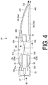
- FIG. 4 is a view illustrating the flow of air along the blade upper surface 23a and the blade lower surface 23b.
- FIG. 5 is a view illustrating the flow of air in the upper leading edge flow path 31, the lower leading edge flow path 32, and the trailing edge flow path 33.
- a high-speed airflow generated by the thrust fan 50 flows from the leading edge 22a of the blade body 20 along the blade upper surface 23a and the blade lower surface 23b toward the trailing edge 22b.
- the thrust fan 50 since the thrust fan 50 includes the duct 51, the airflow is smoothly guided to the blade upper surface 23a and the blade lower surface 23b. Accordingly, the airflow (exhaust gas) of the thrust fan 50 can be used to improve the lift force generated in the blade body 20. Therefore, the lift force can be increased while the aircraft 1 is being propelled by the thrust fan 50.
- the airflow flowing through the blade upper surface 23a flows so as to cover the opening on the blade upper surface 23a side of the housing section 21.
- the airflow flowing through the blade lower surface 23b flows so as to cover the opening on the blade lower surface 23b side of the housing section 21. Accordingly, the upper and lower surfaces of the housing section 21 are covered without providing a structural cover. Therefore, the passage of air between the blade upper surface 23a and the blade lower surface 23b via the housing section 21 can be prevented.
- a high-speed airflow generated by the thrust fan 50 is guided to the upper leading edge flow path 31 and the lower leading edge flow path 32 in addition to the blade upper surface 23a and the blade lower surface 23b.
- the air introduced from the inlet 31a of the upper leading edge flow path 31 is blown out from the outlet 31b after passing through the upper leading edge flow path 31.
- the air introduced from the inlet 31a increases in speed due to the change in the flow path width of the upper leading edge flow path 31 (refer to FIG. 3 ). Since the outlet 31b is on the blade upper surface 23a side relative to the lift fan 40 in the blade thickness direction, the air blown out from the outlet 31b flows so as to cover the blade upper surface 23a side of the lift fan 40 in the housing section 21.
- the air introduced from the inlet 32a of the lower leading edge flow path 32 is blown out from the outlet 32b after passing through the lower leading edge flow path 32.
- the air introduced from the inlet 31a increases in speed due to the change in the flow path width of the upper leading edge flow path 31 (refer to FIG. 3 ). Since the outlet 32b is on the blade lower surface 23b side relative to the lift fan 40 in the blade thickness direction, the air blown out from the outlet 32b flows so as to cover the blade lower surface 23b side of the lift fan 40 in the housing section 21.
- the upper and lower portions of the lift fan 40 are covered without providing a structural cover (for example, a mechanism such as a louver). Therefore, the passage of air between the blade upper surface 23a and the blade lower surface 23b via the housing section 21 can further be prevented.
- a structural cover for example, a mechanism such as a louver
- the air introduced from the two inlets 33a is merged in the trailing edge flow path 33, the air is blown out from the outlet 33b formed in the blade upper surface 23a.
- the air blown out from the outlet 32b flows along the blade upper surface 23a. Accordingly, it is possible to suppress peeling on the blade upper surface 23a on the trailing edge 22b side of the blade body 20 (the trailing edge 22b side relative to the outlet 32b).
- the air can be blown out in a wide range in the blade width direction due to a change in the flow path width of the trailing edge flow path 33 (refer to FIG. 3 ), and the effect of peeling suppression can be achieved in a wide range in the blade width direction.
- the present embodiment provides the blade body 20 including the housing section 21 that penetrates in the blade thickness direction between the leading edge 22a and the trailing edge 22b; the lift fan 40 that is provided inside the housing section 21 and generates an airflow in the blade thickness direction; and the thrust fan 50 that is provided at the leading edge 22a of the blade body 20, and generates an airflow from the leading edge 22a toward the trailing edge 22b on the blade upper surface 23a and the blade lower surface 23b of the blade body 20.
- a high-speed airflow generated by the thrust fan 50 along the blade upper surface 23a and the blade lower surface 23b covers the upper and lower surfaces of the housing section 21.
- the upper and lower surfaces of the housing section 21 are covered without providing a structural cover, and the passage of air between the blade upper surface 23a and the blade lower surface 23b via the housing section 21 can be prevented without increasing weight. Accordingly, it is possible to suppress deterioration of performance of the blade body 20.
- a high-speed airflow generated by the thrust fan 50 passes through the blade upper surface 23a and the blade lower surface 23b to obtain a greater lift force.
- the air from the thrust fan 50 can be guided to the blade upper surface 23a side of the lift fan 40 via the upper leading edge flow path 31. Accordingly, since it is possible to cover the blade upper surface 23a side of the lift fan 40 by a high-speed airflow from the thrust fan 50 without providing a structural cover, it is possible to further prevent the passage of air between the blade upper surface 23a and the blade lower surface 23b via the housing section 21 without increasing weight. Similarly, the air from the thrust fan 50 can be guided to the blade lower surface 23b side of the lift fan 40 via the lower leading edge flow path 32.
- the passage of air between the blade upper surface 23a and the blade lower surface 23b can further be prevented without increasing weight.
- the trailing edge flow path 33 is formed inside the blade body 20, air can be guided from the housing section 21 to the blade upper surface 23a on the trailing edge 22b side relative to the housing section 21. Accordingly, the air guided to the housing section 21 can be efficiently drawn in, and the flow of air generated on the upper and lower surfaces of the lift fan 40 in the housing section 21 can be smoothed. In addition, by guiding the air to the blade upper surface 23a, it is possible to suppress peeling on the trailing edge 22b side of the blade body 20.
- a plurality of housing sections 21 are formed between the leading edge 22a and the trailing edge 22b along the chord direction.
- One lift fan 40 is housed in each of the housing sections 21.
- an upper intermediate flow path 34 and a lower intermediate flow path 35 are formed on the inside of the blade body 20.
- the upper intermediate flow path 34 is a flow path that causes one housing section 21 and another housing section 21 to communicate with each other.
- an opening on the one housing section 21 side is an inlet 34a, and an opening on the other housing section 21 side is an outlet 34b.
- the inlet 34a and the outlet 34b are located on the blade upper surface 23a side relative to the lift fan 40 in the blade thickness direction.
- the lower intermediate flow path 35 is a flow path that causes one housing section 21 and another housing section 21 to communicate with each other.
- an opening on the one housing section 21 side is an inlet 35a, and an opening on the other housing section 21 side is an outlet 35b.
- the one housing section 21 referred to here is the housing section 21 positioned on the leading edge 22a side in the chord direction
- the other housing section 21 is the housing section 21 positioned on the trailing edge 22b side in the chord direction.
- the upstream side is the one housing section 21, and the downstream side is the other housing section 21.
- the inlet 34a and the outlet 34b are located on the blade lower surface 23b side relative to the lift fan 40 in the blade thickness direction.
- the air introduced from the inlet 34a of the upper intermediate flow path 34 is blown out from the outlet 34b after passing through the upper intermediate flow path 34.
- the outlet 34b is located on the blade upper surface 23a side relative to the lift fan 40 in the blade thickness direction, and thus, the air blown out from the outlet 34b flows so as to cover the blade upper surface 23a side of the lift fan 40 in the other housing section 21.
- the air introduced from the inlet 35a of the lower intermediate flow path 35 is blown out from the outlet 35b after passing through the lower intermediate flow path 35. Since the outlet 35b is located on the blade lower surface 23b side relative to the lift fan 40 in the blade thickness direction, the air blown out from the outlet 35b flows so as to cover the blade lower surface 23b side of the lift fan 40 in the housing section 21.
- the upper and lower portions of the lift fan 40 housed in the other housing section 21 are covered without providing a structural cover. Therefore, the passage of air between the blade upper surface 23a and the blade lower surface 23b via the housing section 21 can further be prevented.
- the blade according to one aspect of the present disclosure includes: the blade body (20) configured to include the housing section (21) that penetrates in the blade thickness direction between the leading edge (22a) and the trailing edge (22b); the lift fan (40) provided inside the housing section (21) and configured to generate an airflow in the blade thickness direction; and the thrust fan (50) provided at the leading edge (22a) of the blade body (20) and configured to generate an airflow from the leading edge (22a) toward the trailing edge (22b) on the blade upper surface (23a) and the blade lower surface (23b) of the blade body (20).
- the blade according to the present aspect includes the blade body (20) configured to include the housing section (21) that penetrates in the blade thickness direction between the leading edge (22a) and the trailing edge (22b); the lift fan (40) provided inside the housing section (21) and configured to generate an airflow in the blade thickness direction; and the thrust fan (50) provided at the leading edge (22a) of the blade body (20) and configured to generate an airflow from the leading edge (22a) toward the trailing edge (22b) on the blade upper surface (23a) and the blade lower surface (23b) of the blade body (20), a high-speed airflow generated by the thrust fan (50) along the blade upper surface (23a) and the blade lower surface (23b) covers the upper and lower surfaces (the blade upper surface (23a) and the blade lower surface (23b)) of the housing section (21).
- the upper and lower surfaces of the housing section (21) are covered without providing a structural cover, and the passage of air between the blade upper surface (23a) and the blade lower surface (23b) via the housing section (21) can be prevented without increasing weight. Accordingly, it is possible to suppress deterioration of performance of the blade body (20).
- the high-speed airflow generated by the thrust fan (50) passes through the blade surfaces to obtain a greater lift force.
- an electric motor is suitably used to drive the thrust fan (50) and the lift fan (40).
- the upper leading edge flow path (31) that causes the leading edge (22a) provided with the thrust fan (50) and the housing section (21) to communicate with each other, and guides air to the blade upper surface (23a) side of the lift fan (40)
- the lower leading edge flow path (32) that causes the leading edge (22a) provided with the thrust fan (50) and the housing section (21) to communicate with each other, and guides air to the blade lower surface (23b) side of the lift fan (40).
- the air from the thrust fan (50) can be guided to the blade upper surface (23a) side of the lift fan (40) via the upper leading edge flow path (31).
- the trailing edge flow path (33) that causes the housing section (21) and the blade upper surface (23a) on the trailing edge (22b) side from the housing section (21) to communicate with each other.
- the air can be guided from the housing section (21) to the blade upper surface (23a) on the trailing edge (22b) side from the housing section (21). Accordingly, the air guided to the housing section (21) can be efficiently drawn in, and the flow of air generated on the upper and lower surfaces of the lift fan (40) in the housing section (21) can smoothed.
- the air by guiding the air to the blade upper surface (23a), it is possible to suppress peeling on the trailing edge (22b) side of the blade body (20).
- a plurality of the housing sections (21) are formed at a plurality of locations along the chord direction, and a plurality of the lift fans (40) are provided corresponding to the plurality of housing sections (21).
- the thrust force during takeoff and landing generated by the lift fan (40) can be increased overall.
- the upper intermediate flow path (34) that causes one of the housing sections (21) and another of the housing sections (21) to communicate with each other, and guides air from the one of the housing sections (21) to the blade upper surface (23a) side of the lift fan (40) housed in the other of the housing sections (21), and the lower intermediate flow path (35) that causes one of the housing sections (21) and another of the housing sections (21) to communicate with each other, and guides air from the one of the housing sections (21) to the blade lower surface (23b) side of the lift fan (40) housed in the other of the housing sections (21).
- the upper intermediate flow path (34) that causes one of the housing sections (21) and another of the housing sections (21) to communicate with each other, and guides air from the one of the housing sections (21) to the blade upper surface (23a) side of the lift fan (40) housed in the other of the housing sections (21)
- the lower intermediate flow path (35) that causes one of the housing sections (21) and another of the housing sections (21) to communicate with each other, and guides air from the one of the housing sections (21) to the blade lower surface (23b) side of the lift fan (40) housed in the other of the housing sections (21)
- the air from the one of the housing sections (21) can be guided to the blade upper surface (23a) side of the lift fan (40) via the upper intermediate flow path (34).
- the thrust fan (50) is a ducted fan.
- the thrust fan (50) is a ducted fan, an airflow having a higher speed can be generated on the downstream side of the thrust fan (50).
- an aircraft according to another aspect of the present disclosure includes the above-described blade (10).
Landscapes
- Engineering & Computer Science (AREA)
- Aviation & Aerospace Engineering (AREA)
- Mechanical Engineering (AREA)
- Structures Of Non-Positive Displacement Pumps (AREA)
Abstract
Object
Provided are a wing and an aircraft that can prevent the passage of air between a wing upper surface and a wing lower surface without increasing weight, and suppress deterioration of performance of the wing body.
Solving Means
Provided are a wing body 20 configured to include a housing section 21 that penetrates in a wing thickness direction between a leading edge 22a and a trailing edge 22b; a lift fan 40 provided inside the housing section 21 and configured to generate an airflow in the wing thickness direction; and a thrust fan 50 provided at the leading edge 22a of the wing body 20 and configured to generate an airflow from the leading edge 22a toward the trailing edge 22b on a wing upper surface 23a and a wing lower surface 23b of the wing body 20.
Description
- The present disclosure relates to a blade and an aircraft.
- In recent years, development in the motorization of aircraft has been actively carried out in order to improve the performance of power electronics, and one said development is a vertical take-off & landing (VTOL) type aircraft.
- The type of airframe used in an electric VTOL aircraft varies depending on requirements such as cruise speed, cruise range, and payload. For example, in a case where a fast cruise speed or a long cruise range is required, a tiltwing aircraft or a tiltrotor aircraft having a main wing is often employed.
- However, when the main wing or the rotor is tilted (inclined), stable control of the flight becomes difficult. Thus, in a case where the cruise speed is slow and the cruise range is short, a fixed-rotor aircraft is often employed.
- In recent years, there has been an increase in the need for long distance transport, and the need for tiltwing aircraft or tiltrotor aircraft using a dispersion fan is expected to increase by taking advantage of motorization in the future.
- However, the mechanism for tilting a main wing and a rotor increases the weight of the airframe, and as a result, there have been problems such as increased power consumption or reduced flight stability. Therefore, for example, employing a VTOL aircraft (so-called compound aircraft) in which a lift fan and a thrust fan are separately mounted as disclosed in
Patent Literature 1 has been considered. - Patent Literature 1:
US 2019/0,291,860 A - In a configuration where the lift fan and the thrust fan are mounted separately, only the thrust fan is used while cruising, which is the period not including takeoff and landing, and thus, the lift fan acts as a drag element that inhibits the flow of air.
- In addition, as in the VTOL aircraft disclosed in
Patent Literature 1, even in a configuration in which the thrust fan is provided at the trailing edge of the main wing and the lift fan is housed inside the main wing, the space in which the lift fan is housed causes a blade upper surface and a blade lower surface to communicate with each other and allow air to pass through, and there is a possibility that the performance as a blade deteriorates. In contrast,Patent Literature 1 also discloses a louver that covers the housing space of the lift fan, but the louver and a mechanism for opening and closing the louver increase the weight of the airframe. As a result, there is a problem such as increase in power consumption or deterioration of flight stability. - In view of such circumstances, an object of the present disclosure is to provide a blade and an aircraft capable of preventing the passage of air between a blade upper surface and a blade lower surface without increasing weight, to thereby suppress deterioration of performance of the blade body.
- From the viewpoint of solving the above-described problem, the blade and the aircraft of the present disclosure adopt the following technique.
- That is, according to one aspect of the present disclosure, there is provided a blade including: a blade body configured to include a housing section that penetrates in a blade thickness direction between a leading edge and a trailing edge; a lift fan that is provided inside the housing section and is configured to generate an airflow in the blade thickness direction; and a thrust fan that is provided at the leading edge of the blade body and is configured to generate an airflow from the leading edge toward the trailing edge on a blade upper surface and a blade lower surface of the blade body.
- In addition, an aircraft according to another aspect of the present disclosure includes the above-described blade.
- According to the blade and the aircraft of the present disclosure, it is possible to prevent the passage of air between the blade upper surface and the blade lower surface without increasing weight, and suppress deterioration of performance of the blade body.
-
-
FIG. 1 is a perspective view of an aircraft including blades according to an embodiment of the present disclosure. -
FIG. 2 is a cross-sectional view of a blade along the line II-II ofFIG. 1 . -
FIG. 3 is a plan view of the blade viewed from the arrow A illustrated inFIG. 1 . -
FIG. 4 is a view illustrating a flow of air along a blade upper surface and a blade lower surface. -
FIG. 5 is a view illustrating the flow of air in an upper leading edge flow path, a lower leading edge flow path, and a trailing edge flow path. -
FIG. 6 is a cross-sectional view of a blade along the line II-II (refer toFIG. 1 ) according to a modified example. - Hereinafter, a blade and an aircraft according to an embodiment of the present disclosure will be described with reference to the drawings.
- An outline of a configuration of a
blade 10 will be described below with reference toFIGS. 1 to 3 . -
FIG. 1 is a perspective view of anaircraft 1 including theblades 10.FIG. 2 is a cross-sectional view of theblade 10 along the line II-II ofFIG. 1 .FIG. 3 is a plan view of theblade 10 viewed from the arrow A illustrated inFIG. 1 . - As illustrated in
FIG. 1 , theaircraft 1 is a VTOL aircraft (a so-called compound aircraft) with an airframe in which a lift fan and a thrust fan are separately mounted. Eachblade 10 is preferably employed in the blade structure of theaircraft 1. - Hereinafter, the configuration of the
blade 10 will be described in detail, but for ease of description, first, a case where onelift fan 40 is provided on one of theblades 10 will be described as an example. However, actually, as illustrated inFIG. 1 , a plurality oflift fans 40 may be provided along the chord direction. - As illustrated in
FIG. 2 , eachblade 10 includes ablade body 20, thelift fan 40, and athrust fan 50. - The
blade body 20 is a known blade type in which the blade thickness changes from a leadingedge 22a toward atrailing edge 22b. In theblade body 20, ahousing section 21 is formed between the leadingedge 22a and thetrailing edge 22b. - The
housing section 21 is a space that penetrates from a bladeupper surface 23a to a bladelower surface 23b in the blade thickness direction. As illustrated inFIG. 3 , thehousing section 21 is a cylindrical space. As illustrated inFIGS. 2 and3 , thelift fan 40 is housed in thehousing section 21. - As illustrated in
FIG. 2 , thelift fan 40 is a fan that rotates about an axis XL and generates an airflow in the blade thickness direction. Thelift fan 40 is mainly used for takeoff and landing (ascending/descending) of theaircraft 1. Thelift fan 40 is driven by an electric motor, for example. - The direction of the axis XL of the
lift fan 40 substantially matches the blade thickness direction of the blade body 20 (that is, the penetrating direction of the housing section 21). - The
lift fan 40 is fully housed in thehousing section 21 and does not protrude outward from the bladeupper surface 23a and the bladelower surface 23b. - As illustrated in
FIGS. 2 and3 , thethrust fan 50 is a fan that is provided on the leadingedge 22a of theblade body 20 and rotates about an axis XT, and generates an airflow along theblade body 20. Thethrust fan 50 is mainly used for cruising (propelling) of theaircraft 1. Thethrust fan 50 is driven by an electric motor, for example. - The direction of the axis XT of the
thrust fan 50 substantially matches the chord direction of the blade body 20 (that is, the direction from the leadingedge 22a toward thetrailing edge 22b). Thethrust fan 50 is a so-called ducted fan provided with aduct 51. As illustrated inFIG. 2 , the diameter of thethrust fan 50 is preferably approximately the same as the maximum blade thickness of theblade body 20. Accordingly, the airflow generated by thethrust fan 50 can flow to theblade body 20 side without loss. - As illustrated in
FIG. 3 , a plurality ofthrust fans 50 may be provided in the blade width direction. Accordingly, an airflow can be generated by thethrust fan 50 in a wide range in the blade width direction. - As illustrated in
FIG. 2 , on the inside theblade body 20, an upper leadingedge flow path 31, a lower leadingedge flow path 32, and a trailingedge flow path 33 are formed. - The upper leading
edge flow path 31 is a flow path that causes the leadingedge 22a and thehousing section 21 to communicate with each other in theblade body 20 on which thethrust fan 50 is installed. In the upper leadingedge flow path 31, an opening on theleading edge 22a side is aninlet 31a, and an opening on thehousing section 21 side is anoutlet 31b. - The
inlet 31a is located on the bladeupper surface 23a side relative to the axis XT in the blade thickness direction. In addition, theoutlet 31b is located on the bladeupper surface 23a side relative to thelift fan 40 in the blade thickness direction. Accordingly, the air introduced from theinlet 31a is guided to the bladeupper surface 23a side of thelift fan 40. - The lower leading
edge flow path 32 is a flow path that causes theleading edge 22a and thehousing section 21 to communicate with each other in theblade body 20 on which thethrust fan 50 is installed. In the lower leadingedge flow path 32, an opening on theleading edge 22a side is aninlet 32a, and an opening on thehousing section 21 side is anoutlet 32b. - The
inlet 32a is located on the bladelower surface 23b side relative to the axis XT in the blade thickness direction. In addition, theoutlet 32b is located on the bladelower surface 23b side relative to thelift fan 40 in the blade thickness direction. Accordingly, the air introduced from theinlet 32a is guided to the bladelower surface 23b side of thelift fan 40. - The trailing
edge flow path 33 is a flow path that causes thehousing section 21 and the bladeupper surface 23a on the trailingedge 22b side relative to thehousing section 21 to communicate with each other. In the trailingedge flow path 33, an opening on thehousing section 21 side is aninlet 33a, and an opening on the bladeupper surface 23a side is anoutlet 33b. - Two
inlets 33a are located on the bladeupper surface 23a side and the bladelower surface 23b side, respectively, relative to thelift fan 40 in the blade thickness direction. Meanwhile, theoutlet 33b is provided only on the bladeupper surface 23a side. Accordingly, after the air introduced from each of theinlets 33a has been merged in the trailingedge flow path 33, the air is guided to the bladeupper surface 23a on the trailingedge 22b side relative to thehousing section 21. - As illustrated in
FIG. 3 , the upper leadingedge flow path 31, the lower leadingedge flow path 32, and the trailingedge flow path 33 are formed wide in the blade width direction. - With this configuration, the upper leading
edge flow path 31 and the lower leadingedge flow path 32 gradually contract in a direction from theinlets outlets inlets outlets - In addition, the trailing
edge flow path 33 gradually widens in a direction from theinlet 33a toward theoutlet 33b. Accordingly, the air can be blown out in a wide range in the blade width direction, and the effects of peeling suppression, which will be described later, can be achieved in a wide range in the blade width direction. - The flow of the air in the
blades 10 will be described with reference toFIGS. 4 and5 . -
FIG. 4 is a view illustrating the flow of air along the bladeupper surface 23a and the bladelower surface 23b.FIG. 5 is a view illustrating the flow of air in the upper leadingedge flow path 31, the lower leadingedge flow path 32, and the trailingedge flow path 33. - As illustrated in
FIG. 4 , a high-speed airflow generated by thethrust fan 50 flows from theleading edge 22a of theblade body 20 along the bladeupper surface 23a and the bladelower surface 23b toward the trailingedge 22b. At this time, since thethrust fan 50 includes theduct 51, the airflow is smoothly guided to the bladeupper surface 23a and the bladelower surface 23b. Accordingly, the airflow (exhaust gas) of thethrust fan 50 can be used to improve the lift force generated in theblade body 20. Therefore, the lift force can be increased while theaircraft 1 is being propelled by thethrust fan 50. - The airflow flowing through the blade
upper surface 23a flows so as to cover the opening on the bladeupper surface 23a side of thehousing section 21. In addition, the airflow flowing through the bladelower surface 23b flows so as to cover the opening on the bladelower surface 23b side of thehousing section 21. Accordingly, the upper and lower surfaces of thehousing section 21 are covered without providing a structural cover. Therefore, the passage of air between the bladeupper surface 23a and the bladelower surface 23b via thehousing section 21 can be prevented. - As illustrated in
FIG. 5 , a high-speed airflow generated by thethrust fan 50 is guided to the upper leadingedge flow path 31 and the lower leadingedge flow path 32 in addition to the bladeupper surface 23a and the bladelower surface 23b. - The air introduced from the
inlet 31a of the upper leadingedge flow path 31 is blown out from theoutlet 31b after passing through the upper leadingedge flow path 31. At this time, the air introduced from theinlet 31a increases in speed due to the change in the flow path width of the upper leading edge flow path 31 (refer toFIG. 3 ). Since theoutlet 31b is on the bladeupper surface 23a side relative to thelift fan 40 in the blade thickness direction, the air blown out from theoutlet 31b flows so as to cover the bladeupper surface 23a side of thelift fan 40 in thehousing section 21. - The air introduced from the
inlet 32a of the lower leadingedge flow path 32 is blown out from theoutlet 32b after passing through the lower leadingedge flow path 32. At this time, the air introduced from theinlet 31a increases in speed due to the change in the flow path width of the upper leading edge flow path 31 (refer toFIG. 3 ). Since theoutlet 32b is on the bladelower surface 23b side relative to thelift fan 40 in the blade thickness direction, the air blown out from theoutlet 32b flows so as to cover the bladelower surface 23b side of thelift fan 40 in thehousing section 21. - Accordingly, the upper and lower portions of the
lift fan 40 are covered without providing a structural cover (for example, a mechanism such as a louver). Therefore, the passage of air between the bladeupper surface 23a and the bladelower surface 23b via thehousing section 21 can further be prevented. - The air which is guided from the upper leading
edge flow path 31 and the lower leadingedge flow path 32 to thehousing section 21, and covers the upper and lower portions of thelift fan 40, is guided from the twoinlets 33a to the trailingedge flow path 33. - After the air introduced from the two
inlets 33a is merged in the trailingedge flow path 33, the air is blown out from theoutlet 33b formed in the bladeupper surface 23a. The air blown out from theoutlet 32b flows along the bladeupper surface 23a. Accordingly, it is possible to suppress peeling on the bladeupper surface 23a on the trailingedge 22b side of the blade body 20 (the trailingedge 22b side relative to theoutlet 32b). At this time, the air can be blown out in a wide range in the blade width direction due to a change in the flow path width of the trailing edge flow path 33 (refer toFIG. 3 ), and the effect of peeling suppression can be achieved in a wide range in the blade width direction. - According to the present embodiment, the following effects are obtained.
- The present embodiment provides the
blade body 20 including thehousing section 21 that penetrates in the blade thickness direction between theleading edge 22a and the trailingedge 22b; thelift fan 40 that is provided inside thehousing section 21 and generates an airflow in the blade thickness direction; and thethrust fan 50 that is provided at theleading edge 22a of theblade body 20, and generates an airflow from theleading edge 22a toward the trailingedge 22b on the bladeupper surface 23a and the bladelower surface 23b of theblade body 20. Thus, a high-speed airflow generated by thethrust fan 50 along the bladeupper surface 23a and the bladelower surface 23b covers the upper and lower surfaces of thehousing section 21. Therefore, the upper and lower surfaces of thehousing section 21 are covered without providing a structural cover, and the passage of air between the bladeupper surface 23a and the bladelower surface 23b via thehousing section 21 can be prevented without increasing weight. Accordingly, it is possible to suppress deterioration of performance of theblade body 20. - In addition, a high-speed airflow generated by the
thrust fan 50 passes through the bladeupper surface 23a and the bladelower surface 23b to obtain a greater lift force. - Further, since the upper leading
edge flow path 31 and the lower leadingedge flow path 32 are formed inside the blade body, the air from thethrust fan 50 can be guided to the bladeupper surface 23a side of thelift fan 40 via the upper leadingedge flow path 31. Accordingly, since it is possible to cover the bladeupper surface 23a side of thelift fan 40 by a high-speed airflow from thethrust fan 50 without providing a structural cover, it is possible to further prevent the passage of air between the bladeupper surface 23a and the bladelower surface 23b via thehousing section 21 without increasing weight. Similarly, the air from thethrust fan 50 can be guided to the bladelower surface 23b side of thelift fan 40 via the lower leadingedge flow path 32. Accordingly, since it is possible to cover the bladelower surface 23b side of thelift fan 40 by using a high-speed airflow from thethrust fan 50 without providing a structural cover, the passage of air between the bladeupper surface 23a and the bladelower surface 23b can further be prevented without increasing weight. - In addition, since the trailing
edge flow path 33 is formed inside theblade body 20, air can be guided from thehousing section 21 to the bladeupper surface 23a on the trailingedge 22b side relative to thehousing section 21. Accordingly, the air guided to thehousing section 21 can be efficiently drawn in, and the flow of air generated on the upper and lower surfaces of thelift fan 40 in thehousing section 21 can be smoothed. In addition, by guiding the air to the bladeupper surface 23a, it is possible to suppress peeling on the trailingedge 22b side of theblade body 20. - In the above-described description, a case where one
lift fan 40 is provided with respect to one of theblades 10 for simplicity has been described as an example, but a plurality oflift fans 40 may be provided along the chord direction. - As illustrated in
FIG. 6 , in theblade body 20, a plurality ofhousing sections 21 are formed between theleading edge 22a and the trailingedge 22b along the chord direction. Onelift fan 40 is housed in each of thehousing sections 21. - The flow of air in the blade
upper surface 23a and the bladelower surface 23b and in the upper leadingedge flow path 31, the lower leadingedge flow path 32, and the trailingedge flow path 33 is as described above. - On the inside of the
blade body 20, an upperintermediate flow path 34 and a lowerintermediate flow path 35 are formed. - The upper
intermediate flow path 34 is a flow path that causes onehousing section 21 and anotherhousing section 21 to communicate with each other. In the upperintermediate flow path 34, an opening on the onehousing section 21 side is aninlet 34a, and an opening on theother housing section 21 side is anoutlet 34b. - The
inlet 34a and theoutlet 34b are located on the bladeupper surface 23a side relative to thelift fan 40 in the blade thickness direction. - The lower
intermediate flow path 35 is a flow path that causes onehousing section 21 and anotherhousing section 21 to communicate with each other. In the lowerintermediate flow path 35, an opening on the onehousing section 21 side is aninlet 35a, and an opening on theother housing section 21 side is anoutlet 35b. - Note that the one
housing section 21 referred to here is thehousing section 21 positioned on theleading edge 22a side in the chord direction, and theother housing section 21 is thehousing section 21 positioned on the trailingedge 22b side in the chord direction. In other words, in the flow direction of the airflow generated by thethrust fan 50, the upstream side is the onehousing section 21, and the downstream side is theother housing section 21. - The
inlet 34a and theoutlet 34b are located on the bladelower surface 23b side relative to thelift fan 40 in the blade thickness direction. - The air introduced from the
inlet 34a of the upperintermediate flow path 34 is blown out from theoutlet 34b after passing through the upperintermediate flow path 34. Theoutlet 34b is located on the bladeupper surface 23a side relative to thelift fan 40 in the blade thickness direction, and thus, the air blown out from theoutlet 34b flows so as to cover the bladeupper surface 23a side of thelift fan 40 in theother housing section 21. - The air introduced from the
inlet 35a of the lowerintermediate flow path 35 is blown out from theoutlet 35b after passing through the lowerintermediate flow path 35. Since theoutlet 35b is located on the bladelower surface 23b side relative to thelift fan 40 in the blade thickness direction, the air blown out from theoutlet 35b flows so as to cover the bladelower surface 23b side of thelift fan 40 in thehousing section 21. - Accordingly, the upper and lower portions of the
lift fan 40 housed in theother housing section 21 are covered without providing a structural cover. Therefore, the passage of air between the bladeupper surface 23a and the bladelower surface 23b via thehousing section 21 can further be prevented. - The blade and the aircraft according to one embodiment described above are understood, for example, as follows.
- That is, the blade according to one aspect of the present disclosure includes: the blade body (20) configured to include the housing section (21) that penetrates in the blade thickness direction between the leading edge (22a) and the trailing edge (22b); the lift fan (40) provided inside the housing section (21) and configured to generate an airflow in the blade thickness direction; and the thrust fan (50) provided at the leading edge (22a) of the blade body (20) and configured to generate an airflow from the leading edge (22a) toward the trailing edge (22b) on the blade upper surface (23a) and the blade lower surface (23b) of the blade body (20).
- Since the blade according to the present aspect includes the blade body (20) configured to include the housing section (21) that penetrates in the blade thickness direction between the leading edge (22a) and the trailing edge (22b); the lift fan (40) provided inside the housing section (21) and configured to generate an airflow in the blade thickness direction; and the thrust fan (50) provided at the leading edge (22a) of the blade body (20) and configured to generate an airflow from the leading edge (22a) toward the trailing edge (22b) on the blade upper surface (23a) and the blade lower surface (23b) of the blade body (20), a high-speed airflow generated by the thrust fan (50) along the blade upper surface (23a) and the blade lower surface (23b) covers the upper and lower surfaces (the blade upper surface (23a) and the blade lower surface (23b)) of the housing section (21). Therefore, the upper and lower surfaces of the housing section (21) are covered without providing a structural cover, and the passage of air between the blade upper surface (23a) and the blade lower surface (23b) via the housing section (21) can be prevented without increasing weight. Accordingly, it is possible to suppress deterioration of performance of the blade body (20).
- In addition, the high-speed airflow generated by the thrust fan (50) passes through the blade surfaces to obtain a greater lift force.
- Further, an electric motor is suitably used to drive the thrust fan (50) and the lift fan (40).
- In the blade according to the aspect of the present disclosure, on the inside of the blade body (20), there are formed the upper leading edge flow path (31) that causes the leading edge (22a) provided with the thrust fan (50) and the housing section (21) to communicate with each other, and guides air to the blade upper surface (23a) side of the lift fan (40), and the lower leading edge flow path (32) that causes the leading edge (22a) provided with the thrust fan (50) and the housing section (21) to communicate with each other, and guides air to the blade lower surface (23b) side of the lift fan (40).
- In the blade according to the present aspect, since, on the inside of the blade body (20), there are formed the upper leading edge flow path (31) that causes the leading edge (22a) provided with the thrust fan (50) and the housing section (21) to communicate with each other, and guides air to the blade upper surface (23a) side of the lift fan (40), and the lower leading edge flow path (32) that causes the leading edge (22a) provided with the thrust fan (50) and the housing section (21) to communicate with each other, and guides air to the blade lower surface (23b) side of the lift fan (40), the air from the thrust fan (50) can be guided to the blade upper surface (23a) side of the lift fan (40) via the upper leading edge flow path (31). Accordingly, since it is possible to cover the blade upper surface (23a) side of the lift fan (40) by using a high-speed airflow from the thrust fan (50) without providing a structural cover, it is possible to prevent the passage of air the blade upper surface (23a) and the blade lower surface (23b) via the housing section (21) without increasing weight. Similarly, the air from the thrust fan (50) can be guided to the blade lower surface (23b) side of the lift fan (40) via the lower leading edge flow path (32). Accordingly, since it is possible to cover the blade lower surface (23b) side of the lift fan (40) by using a high-speed airflow from the thrust fan (50) without providing a structural cover, it is possible to further prevent the passage of air between the blade upper surface (23a) and the blade lower surface (23b) without increasing weight.
- In addition, in the blade according to the aspect of the present disclosure, on the inside of the blade body (20), there is formed the trailing edge flow path (33) that causes the housing section (21) and the blade upper surface (23a) on the trailing edge (22b) side from the housing section (21) to communicate with each other.
- In the blade according to the present aspect, since, on the inside of the blade body (20), there is formed the trailing edge flow path (33) that causes the housing section (21) and the blade upper surface (23a) on the trailing edge (22b) side from the housing section (21) to communicate with each other, the air can be guided from the housing section (21) to the blade upper surface (23a) on the trailing edge (22b) side from the housing section (21). Accordingly, the air guided to the housing section (21) can be efficiently drawn in, and the flow of air generated on the upper and lower surfaces of the lift fan (40) in the housing section (21) can smoothed. In addition, by guiding the air to the blade upper surface (23a), it is possible to suppress peeling on the trailing edge (22b) side of the blade body (20).
- Further, in the blade according to the aspect of the present disclosure, a plurality of the housing sections (21) are formed at a plurality of locations along the chord direction, and a plurality of the lift fans (40) are provided corresponding to the plurality of housing sections (21).
- In the blade according to the present aspect, since a plurality of housing sections (21) are formed at a plurality of locations along the chord direction, and a plurality of the lift fans (40) are provided corresponding to the plurality of housing sections (21), the thrust force during takeoff and landing generated by the lift fan (40) can be increased overall.
- In addition, in the blade according to the aspect of the present disclosure, in the blade body (20), there are formed the upper intermediate flow path (34) that causes one of the housing sections (21) and another of the housing sections (21) to communicate with each other, and guides air from the one of the housing sections (21) to the blade upper surface (23a) side of the lift fan (40) housed in the other of the housing sections (21), and the lower intermediate flow path (35) that causes one of the housing sections (21) and another of the housing sections (21) to communicate with each other, and guides air from the one of the housing sections (21) to the blade lower surface (23b) side of the lift fan (40) housed in the other of the housing sections (21).
- In the blade according to the present aspect, since, in the blade body (20), there are formed the upper intermediate flow path (34) that causes one of the housing sections (21) and another of the housing sections (21) to communicate with each other, and guides air from the one of the housing sections (21) to the blade upper surface (23a) side of the lift fan (40) housed in the other of the housing sections (21), and the lower intermediate flow path (35) that causes one of the housing sections (21) and another of the housing sections (21) to communicate with each other, and guides air from the one of the housing sections (21) to the blade lower surface (23b) side of the lift fan (40) housed in the other of the housing sections (21), the air from the one of the housing sections (21) can be guided to the blade upper surface (23a) side of the lift fan (40) via the upper intermediate flow path (34). Accordingly, since it is possible to cover the blade upper surface (23a) side of the lift fan (40) without providing a structural cover, it is possible to prevent the passage of air between the blade upper surface (23a) and the blade lower surface (23b) via the housing section (21) without increasing weight. Similarly, the air from the one of the housing sections (21) can be guided to the blade lower surface (23b) side of the lift fan (40) via the lower intermediate flow path (35). Accordingly, since it is possible to cover the blade lower surface (23b) side of the lift fan (40) without providing a structural cover, it is possible to prevent the passage of air between the blade upper surface (23a) and the blade lower surface (23b) without increasing weight.
- In addition, in the blade according to the aspect of the present disclosure, the thrust fan (50) is a ducted fan.
- In the blade according to the present aspect, since the thrust fan (50) is a ducted fan, an airflow having a higher speed can be generated on the downstream side of the thrust fan (50).
- In addition, an aircraft according to another aspect of the present disclosure includes the above-described blade (10).
-
- 1
- Aircraft
- 10
- Blade
- 20
- Blade body
- 21
- Housing section
- 22a
- Leading edge
- 22b
- Trailing edge
- 23a
- Blade upper surface
- 23b
- Blade lower surface
- 31
- Upper leading edge flow path
- 31a
- Inlet
- 31b
- Outlet
- 32
- Lower leading edge flow path
- 32a
- Inlet
- 32b
- Outlet
- 33
- Trailing edge flow path
- 33a
- Inlet
- 33b
- Outlet
- 34
- Upper intermediate flow path
- 34a
- Inlet
- 34b
- Outlet
- 35
- Lower intermediate flow path
- 35a
- Inlet
- 35b
- Outlet
- 40
- Lift fan
- 50
- Thrust fan
- 51
- Duct
Claims (7)
- A blade comprising:a blade body configured to include a housing section that penetrates in a blade thickness direction between a leading edge and a trailing edge;a lift fan provided inside the housing section and configured to generate an airflow in the blade thickness direction; anda thrust fan provided at the leading edge of the blade body and configured to generate an airflow from the leading edge toward the trailing edge on a blade upper surface and a blade lower surface of the blade body.
- The blade according to claim 1, whereinon the inside of the blade body, there are formedan upper leading edge flow path that causes the leading edge provided with the thrust fan and the housing section to communicate with each other, and guides air to the blade upper surface side of the lift fan, anda lower leading edge flow path that causes the leading edge provided with the thrust fan and the housing section to communicate with each other, and guides air to the blade lower surface side of the lift fan.
- The blade according to claim 2, wherein
on the inside of the blade body, there is formed a trailing edge flow path that causes the housing section and the blade upper surface on the trailing edge side relative to the housing section to communicate with each other. - The blade according to any one of claims 1 to 3, whereina plurality of the housing sections are formed at a plurality of locations along a chord direction, anda plurality of the lift fans are provided corresponding to the plurality of housing sections.
- The blade according to claim 4, whereinin the blade body, there are formedan upper intermediate flow path that causes one of the housing sections and another of the housing sections to communicate with each other, and guides air from the one of the housing sections to the blade upper surface side of the lift fan housed in the other of the housing sections, anda lower intermediate flow path that causes one of the housing sections and another of the housing sections to communicate with each other, and guides air from the one of the housing sections to the blade lower surface side of the lift fan housed in the other of the housing sections.
- The blade according to any one of claims 1 to 5, wherein
the thrust fan is a ducted fan. - An aircraft comprising:
the blade according to any one of claims 1 to 6.
Applications Claiming Priority (1)
| Application Number | Priority Date | Filing Date | Title |
|---|---|---|---|
| JP2020053990A JP7346347B2 (en) | 2020-03-25 | 2020-03-25 | wings and aircraft |
Publications (1)
| Publication Number | Publication Date |
|---|---|
| EP3885252A1 true EP3885252A1 (en) | 2021-09-29 |
Family
ID=74346821
Family Applications (1)
| Application Number | Title | Priority Date | Filing Date |
|---|---|---|---|
| EP21153790.7A Withdrawn EP3885252A1 (en) | 2020-03-25 | 2021-01-27 | Wing and aircraft |
Country Status (3)
| Country | Link |
|---|---|
| EP (1) | EP3885252A1 (en) |
| JP (1) | JP7346347B2 (en) |
| CN (1) | CN113443135A (en) |
Cited By (1)
| Publication number | Priority date | Publication date | Assignee | Title |
|---|---|---|---|---|
| CN116119002A (en) * | 2023-04-14 | 2023-05-16 | 成都流体动力创新中心 | Wing flow control system based on duct fan driving cooperative blowing and sucking air |
Citations (3)
| Publication number | Priority date | Publication date | Assignee | Title |
|---|---|---|---|---|
| DE2922221A1 (en) * | 1979-05-31 | 1980-12-04 | Willibald Hiemer | Rotary-wing aircraft with propellers separate - has airstream from propellers discharging downwards into vertical ducting around lift rotors |
| CN108773486A (en) * | 2018-05-31 | 2018-11-09 | 江苏常探机器人有限公司 | It is a kind of with the compound auxiliary wing of ducted fan without the compound rotor aircraft of back pressure formula |
| US20190291860A1 (en) | 2016-10-27 | 2019-09-26 | Mono Aerospace Ip Ltd | Vertical take-off and landing aircraft and control method |
Family Cites Families (15)
| Publication number | Priority date | Publication date | Assignee | Title |
|---|---|---|---|---|
| JPS5822796A (en) * | 1981-08-01 | 1983-02-10 | 高畠 清志 | Duct-fan rear-flow blade-surface induction type high lift mechanism |
| US7267300B2 (en) | 2005-02-25 | 2007-09-11 | The Boeing Company | Aircraft capable of vertical and short take-off and landing |
| US8561935B2 (en) * | 2010-09-17 | 2013-10-22 | Karl F. Milde, Jr. | STOL and/or VTOL aircraft |
| GB201120258D0 (en) | 2011-11-24 | 2012-01-04 | Rolls Royce Plc | An aircraft |
| US9108725B1 (en) * | 2012-11-29 | 2015-08-18 | The Boeing Company | Method and apparatus for robust lift generation |
| WO2016009376A1 (en) * | 2014-07-18 | 2016-01-21 | Pegasus Universal Aerospace (Pty) Ltd. | Vertical take-off and landing aircraft |
| KR101938459B1 (en) | 2016-12-15 | 2019-01-14 | 한국항공우주연구원 | Aircraft |
| US10384776B2 (en) * | 2017-02-22 | 2019-08-20 | Bell Helicopter Textron Inc. | Tiltrotor aircraft having vertical lift and hover augmentation |
| CN207889978U (en) | 2017-05-03 | 2018-09-21 | 南京天钥谷航空科技有限公司 | A kind of Novel land mapping aerial device |
| FR3078098B1 (en) * | 2018-02-16 | 2020-06-19 | Safran Aircraft Engines | PROFILE STRUCTURE IN INCLINED LOCKINGS |
| JP6731604B2 (en) | 2018-03-31 | 2020-07-29 | 中松 義郎 | High-speed drones and other aircraft |
| JP7149116B2 (en) | 2018-06-27 | 2022-10-06 | 新明和工業株式会社 | aircraft |
| CN109263901A (en) | 2018-10-30 | 2019-01-25 | 佛山市神风航空科技有限公司 | A kind of suspension type folding rotor craft |
| CN111422342B (en) | 2019-09-29 | 2022-03-04 | 北京理工大学 | A variable shape fixed wing micro aircraft |
| CN111252239A (en) | 2019-10-12 | 2020-06-09 | 周武双 | Ducted helicopter |
-
2020
- 2020-03-25 JP JP2020053990A patent/JP7346347B2/en active Active
-
2021
- 2021-01-22 CN CN202110086786.3A patent/CN113443135A/en active Pending
- 2021-01-27 EP EP21153790.7A patent/EP3885252A1/en not_active Withdrawn
Patent Citations (3)
| Publication number | Priority date | Publication date | Assignee | Title |
|---|---|---|---|---|
| DE2922221A1 (en) * | 1979-05-31 | 1980-12-04 | Willibald Hiemer | Rotary-wing aircraft with propellers separate - has airstream from propellers discharging downwards into vertical ducting around lift rotors |
| US20190291860A1 (en) | 2016-10-27 | 2019-09-26 | Mono Aerospace Ip Ltd | Vertical take-off and landing aircraft and control method |
| CN108773486A (en) * | 2018-05-31 | 2018-11-09 | 江苏常探机器人有限公司 | It is a kind of with the compound auxiliary wing of ducted fan without the compound rotor aircraft of back pressure formula |
Cited By (2)
| Publication number | Priority date | Publication date | Assignee | Title |
|---|---|---|---|---|
| CN116119002A (en) * | 2023-04-14 | 2023-05-16 | 成都流体动力创新中心 | Wing flow control system based on duct fan driving cooperative blowing and sucking air |
| CN116119002B (en) * | 2023-04-14 | 2023-06-20 | 成都流体动力创新中心 | Wing flow control system based on duct fan driving cooperative blowing and sucking air |
Also Published As
| Publication number | Publication date |
|---|---|
| CN113443135A (en) | 2021-09-28 |
| JP7346347B2 (en) | 2023-09-19 |
| JP2021154759A (en) | 2021-10-07 |
Similar Documents
| Publication | Publication Date | Title |
|---|---|---|
| US12565327B2 (en) | Ejector and airfoil configurations | |
| US11492099B2 (en) | Aircraft nacelle having electric motor and thrust reversing air exhaust flaps | |
| US6113029A (en) | Aircraft capable of hovering and conventional flight | |
| CN106986038A (en) | Aircraft with rear engine | |
| US7611090B2 (en) | Reaction-drive rotorcraft having an adjustable blade jet | |
| EP4011765B1 (en) | A rotary wing aircraft with an asymmetrical rear section | |
| EP3885252A1 (en) | Wing and aircraft | |
| US10220939B2 (en) | Active airflow system and method of reducing drag for aircraft | |
| EP2597038A2 (en) | An Aircraft | |
| US11697493B2 (en) | Rotary wing aircraft with a shrouded tail propeller | |
| EP3090952B1 (en) | Engine nacelle | |
| EP3638587B1 (en) | Winglet ejector configurations | |
| US8876037B2 (en) | Rotorcraft counter-torque control assembly and method | |
| US20210316852A1 (en) | Centrifugal fans for vertical take-off and landing (vtol) aircraft propulsion | |
| Camci et al. | A VTOL-UAV Inlet flow distorti on reducition concept uising a new flow control approach: double-ducted-fan | |
| Camci et al. | A VTOL-UAV inlet flow distortion reduction concept using a new flow control approach: Double-Ducted-Fan (DDF) | |
| AS et al. | Numerical study of the flow around the ducted rotor propulsion with controlled leading part of the ring fairing |
Legal Events
| Date | Code | Title | Description |
|---|---|---|---|
| PUAI | Public reference made under article 153(3) epc to a published international application that has entered the european phase |
Free format text: ORIGINAL CODE: 0009012 |
|
| STAA | Information on the status of an ep patent application or granted ep patent |
Free format text: STATUS: THE APPLICATION HAS BEEN PUBLISHED |
|
| STAA | Information on the status of an ep patent application or granted ep patent |
Free format text: STATUS: THE APPLICATION HAS BEEN WITHDRAWN |
|
| AK | Designated contracting states |
Kind code of ref document: A1 Designated state(s): AL AT BE BG CH CY CZ DE DK EE ES FI FR GB GR HR HU IE IS IT LI LT LU LV MC MK MT NL NO PL PT RO RS SE SI SK SM TR |
|
| 18W | Application withdrawn |
Effective date: 20210907 |