EP3885249A1 - Drive source switching system for marine propulsion device including multiple drive sources, and method of switching drive sources of marine propulsion device - Google Patents
Drive source switching system for marine propulsion device including multiple drive sources, and method of switching drive sources of marine propulsion device Download PDFInfo
- Publication number
- EP3885249A1 EP3885249A1 EP21160995.3A EP21160995A EP3885249A1 EP 3885249 A1 EP3885249 A1 EP 3885249A1 EP 21160995 A EP21160995 A EP 21160995A EP 3885249 A1 EP3885249 A1 EP 3885249A1
- Authority
- EP
- European Patent Office
- Prior art keywords
- drive source
- shift
- driven member
- driving member
- state
- Prior art date
- Legal status (The legal status is an assumption and is not a legal conclusion. Google has not performed a legal analysis and makes no representation as to the accuracy of the status listed.)
- Granted
Links
Images






Classifications
-
- B—PERFORMING OPERATIONS; TRANSPORTING
- B63—SHIPS OR OTHER WATERBORNE VESSELS; RELATED EQUIPMENT
- B63H—MARINE PROPULSION OR STEERING
- B63H20/00—Outboard propulsion units, e.g. outboard motors or Z-drives; Arrangements thereof on vessels
- B63H20/14—Transmission between propulsion power unit and propulsion element
-
- B—PERFORMING OPERATIONS; TRANSPORTING
- B63—SHIPS OR OTHER WATERBORNE VESSELS; RELATED EQUIPMENT
- B63H—MARINE PROPULSION OR STEERING
- B63H21/00—Use of propulsion power plant or units on vessels
- B63H21/20—Use of propulsion power plant or units on vessels the vessels being powered by combinations of different types of propulsion units
-
- B—PERFORMING OPERATIONS; TRANSPORTING
- B63—SHIPS OR OTHER WATERBORNE VESSELS; RELATED EQUIPMENT
- B63H—MARINE PROPULSION OR STEERING
- B63H21/00—Use of propulsion power plant or units on vessels
- B63H21/21—Control means for engine or transmission, specially adapted for use on marine vessels
-
- B—PERFORMING OPERATIONS; TRANSPORTING
- B63—SHIPS OR OTHER WATERBORNE VESSELS; RELATED EQUIPMENT
- B63H—MARINE PROPULSION OR STEERING
- B63H23/00—Transmitting power from propulsion power plant to propulsive elements
- B63H23/02—Transmitting power from propulsion power plant to propulsive elements with mechanical gearing
- B63H23/10—Transmitting power from propulsion power plant to propulsive elements with mechanical gearing for transmitting drive from more than one propulsion power unit
- B63H23/18—Transmitting power from propulsion power plant to propulsive elements with mechanical gearing for transmitting drive from more than one propulsion power unit for alternative use of the propulsion power units
-
- B—PERFORMING OPERATIONS; TRANSPORTING
- B63—SHIPS OR OTHER WATERBORNE VESSELS; RELATED EQUIPMENT
- B63H—MARINE PROPULSION OR STEERING
- B63H20/00—Outboard propulsion units, e.g. outboard motors or Z-drives; Arrangements thereof on vessels
- B63H20/007—Trolling propulsion units
-
- B—PERFORMING OPERATIONS; TRANSPORTING
- B63—SHIPS OR OTHER WATERBORNE VESSELS; RELATED EQUIPMENT
- B63H—MARINE PROPULSION OR STEERING
- B63H21/00—Use of propulsion power plant or units on vessels
- B63H21/20—Use of propulsion power plant or units on vessels the vessels being powered by combinations of different types of propulsion units
- B63H2021/202—Use of propulsion power plant or units on vessels the vessels being powered by combinations of different types of propulsion units of hybrid electric type
- B63H2021/205—Use of propulsion power plant or units on vessels the vessels being powered by combinations of different types of propulsion units of hybrid electric type the second power unit being of the internal combustion engine type, or the like, e.g. a Diesel engine
-
- B—PERFORMING OPERATIONS; TRANSPORTING
- B63—SHIPS OR OTHER WATERBORNE VESSELS; RELATED EQUIPMENT
- B63H—MARINE PROPULSION OR STEERING
- B63H21/00—Use of propulsion power plant or units on vessels
- B63H21/21—Control means for engine or transmission, specially adapted for use on marine vessels
- B63H2021/216—Control means for engine or transmission, specially adapted for use on marine vessels using electric control means
-
- F—MECHANICAL ENGINEERING; LIGHTING; HEATING; WEAPONS; BLASTING
- F16—ENGINEERING ELEMENTS AND UNITS; GENERAL MEASURES FOR PRODUCING AND MAINTAINING EFFECTIVE FUNCTIONING OF MACHINES OR INSTALLATIONS; THERMAL INSULATION IN GENERAL
- F16H—GEARING
- F16H61/00—Control functions within control units of change-speed- or reversing-gearings for conveying rotary motion ; Control of exclusively fluid gearing, friction gearing, gearings with endless flexible members or other particular types of gearing
- F16H61/12—Detecting malfunction or potential malfunction, e.g. fail safe ; Circumventing or fixing failures
-
- Y—GENERAL TAGGING OF NEW TECHNOLOGICAL DEVELOPMENTS; GENERAL TAGGING OF CROSS-SECTIONAL TECHNOLOGIES SPANNING OVER SEVERAL SECTIONS OF THE IPC; TECHNICAL SUBJECTS COVERED BY FORMER USPC CROSS-REFERENCE ART COLLECTIONS [XRACs] AND DIGESTS
- Y02—TECHNOLOGIES OR APPLICATIONS FOR MITIGATION OR ADAPTATION AGAINST CLIMATE CHANGE
- Y02T—CLIMATE CHANGE MITIGATION TECHNOLOGIES RELATED TO TRANSPORTATION
- Y02T70/00—Maritime or waterways transport
- Y02T70/50—Measures to reduce greenhouse gas emissions related to the propulsion system
- Y02T70/5218—Less carbon-intensive fuels, e.g. natural gas, biofuels
- Y02T70/5236—Renewable or hybrid-electric solutions
Definitions
- the present invention relates to drive source switching systems that comprises a drive source switching mechanism that is configured to switch, between a first drive source and a second drive source of a marine propulsion device, and method of switching drive sources of the marine propulsion device.
- marine propulsion devices each including an electric motor and an internal combustion engine as its drive sources have been known.
- the use of an electric motor for a drive source of a marine propulsion device makes speed control of a marine vessel easier at very low speed, and it is suitable for correcting the position of a hull moved due to wind or waves e.g. in fishing.
- Such a marine propulsion device switches its drive source from an internal combustion engine to an electric motor, by moving a shift slider coupled to a propeller shaft, in the axial direction of the propeller shaft, and then meshing protrusions (teeth) provided on the shift slider with a gear (hereinafter, referred to as a "motor driven gear”) driven by the electric motor. It is disclosed in, for example, JP 2017-218016 A .
- said object is solved by a drive source switching system that comprises a drive source switching mechanism that is configured to switch, between a first drive source and a second drive source of a marine propulsion device having the features of independent claim 1. Moreover, according to the present invention said object is solved by method of switching drive sources of the marine propulsion device having the features of independent claim 17. Preferred embodiments are laid down in the dependent claims.
- a drive source switching system for a marine propulsion device comprises a first drive source, a second drive source, and a propeller shaft that rotates blades to generate a propulsive force.
- the drive source switching system further comprises a first driving member that transmits a drive force generated by the first drive source, and a second driving member that transmits a drive force generated by the second drive source.
- the drive source switching system further comprises a first driven member that is movable in an axial direction of the propeller shaft, engageably with the first driving member, and a second driven member that is movable in the axial direction of the propeller shaft, engageably with the second driving member.
- the drive source switching system further comprises a controller configured or programmed to control a movement of the first driven member.
- the first driven member transmits the drive force generated by the first drive source to the propeller shaft when engaged with the first driving member.
- the second driven member transmits a drive force generated by the second drive source to the propeller shaft when engaged with the second driving member.
- the controller moves the first driven member at a first position where the first driven member is not engaged with the first driving member, in the axial direction of the propeller shaft toward the first driving member, the controller moves back the first driven member in a direction of the first position when the first driven member fails to be engaged with the first driving member.
- the controller may move the first driven member toward the first driving member again after the failure.
- a drive source switching system for a marine propulsion device comprises a first drive source, a second drive source, and a propeller shaft that rotates blades to generate a propulsive force.
- the drive source switching system further comprises a drive source switching mechanism that switches, between the first drive source and the second drive source, a drive source that generates a drive force to be transmitted to the propeller shaft.
- the drive source switching system further comprises a controller configured or programmed to control the drive source switching mechanism to switch the drive source between the first drive source and the second drive source.
- the controller temporarily interrupts the switching the drive source between the first drive source and the second drive source.
- the controller may attempt the switching between the first drive source and the second drive source again after the failure.
- a marine propulsion device includes a first drive source, a second drive source, a propeller shaft that rotates blades to generate a propulsive force, a drive source switching mechanism that switches, between the first drive source and the second drive source, a drive source that generates a drive force to be transmitted to the propeller shaft, and a controller.
- a method of switching drive sources of the marine propulsion device comprises controlling, by the controller, the drive source switching mechanism to switch the drive source between the first drive source and the second drive source, and when switching the drive source between the first drive source and the second drive source is failed, temporarily interrupting, by the controller, switching the drive source between the first drive source and the second drive source.
- the controller moves back the first driven member to the direction of the first position when the first driven member fails to be engaged with the first driving member, or, the controller temporarily interrupts the switching between the first drive source and the second drive source when the controller fails to switch between these drive sources. It reduces impossible attempts to switch between the drive sources, resulting in smooth switching of the drive sources.
- FIG. 1 is a side view of a marine vessel to which a drive source switching system for a marine propulsion device according to an embodiment of the present teaching is provided.
- This marine vessel 10 is a planing boat, and includes a hull 11, a plurality of outboard motors 12 which define and function as marine propulsion devices mounted on the hull 11, and a plurality of trim tabs 13.
- a steering wheel 14 and a remote controller 15 which will be described later are provided in the vicinity of a cockpit in the hull 11.
- the outboard motors 12 are mounted on a stern of the hull 11 side by side.
- Each of the outboard motors 12 includes two drive sources.
- One is an engine 16 (a second drive source), which is, e.g., an internal combustion engine, and the other is an electric motor 17 (a first drive source).
- the outboard motors 12 each generates a propulsive force to move the hull 11 by using a propeller 18 (or blades to generate a propulsive force) that is rotatable by a driving force generated by the engine 16 or the electric motor 17.
- Each of the outboard motors 12 is mounted on the hull 11 via a mounting unit 19 such that it is able to turn about a substantially vertical steering axis in the mounting unit 19 in response to a vessel operator's operation of the steering wheel 14. With the outboard motors 12 turning in response to the operation of the steering wheel 14, the marine vessel 10 is steered. Trim tabs 13 are mounted on the stern on the port side and the starboard side such that they are able to swing about a substantially horizontal swing axis in the stern. The trim tabs 13 swinging about the swing axis adjust the lift generated at the stern of the hull 11 to control the posture of the hull 11.
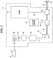
- FIG. 2 is a diagram schematically illustrating the configuration of one of the outboard motors 12 in FIG. 1 .
- the diagram mainly illustrates the engine 16, the electric motor 17 and the control system for switching the drive sources of the outboard motor 12 for explanation purposes, and the control systems for controlling drive forces generated by the drive sources are omitted.
- the outboard motor 12 includes the engine 16, the electric motor 17, and a propeller shaft 20.
- the propeller 18 is connected to the propeller shaft 20 and the propeller shaft 20 rotates the propeller 18 to generate a propulsive force.
- the outboard motor 12 further includes a shaft-like shift slider 21 (first driven member) coupled to the propeller shaft 20.
- the shift slider 21 is not necessarily disposed coaxially with the propeller shaft 20.
- the shift slider 21 is only required to be disposed at a position movable by a shift link mechanism 24 along the rotation axis of the propeller shaft 20.
- the outboard motor 12 further includes an engine-side clutch mechanism 22 and an electric motor-side clutch mechanism 23 that form a drive source switching mechanism.
- the engine-side clutch mechanism 22 switches transmission and non-transmission of the drive force from the engine 16 to the propeller shaft 20.
- the electric motor-side clutch mechanism 23 switches transmission and non-transmission of the drive force from the electric motor 17 to the shift slider 21.
- the outboard motor 12 further includes the shift link mechanism 24 (movement mechanism), an actuator 25 that moves the shift link mechanism 24, and an actuator motor 26 which is, e.g., an electric motor that operates the actuator 25.
- the shift link mechanism 24 is driven by the electric motor and moves the shift slider 21 or a dog clutch 39 which will be described later, in the axial direction of the propeller shaft 20.
- the axial direction of the shift slider 21 and the propeller shaft 20 will hereinafter be referred to simply as "axially" or "the axial direction”.
- the outboard motor 12 further includes an ECU 27 that transmits a drive signal (shift actuator drive signal) to the actuator motor 26, and an actuator head (AH) ECU 28 (controller) that requests the ECU 27 to switch the drive forces in response to an input from the remote controller 15.
- the engine 16 and the engine-side clutch mechanism 22 are connected by an engine drive shaft 29, and the electric motor 17 and the electric motor-side clutch mechanism 23 are connected by a motor drive shaft 30.
- the actuator 25 moves up and down a shift rod 31 that is connected to one end of an L-shaped link arm 32, and a tip of the shift slider 21 is connected to the other end of the link arm 32 via a pusher 33.
- the link arm 32 moves the shift slider 21 in the axial direction by converting the up and down movement of the shift rod 31 into the back and forth movement of the pusher 33.
- the shift slider 21 moves in the axial direction of the shift slider 21 (and the propeller shaft 20) engageably with a motor driven gear 35 which will be described later.
- the actuator 25 may be one that moves the shift rod 31 up and down by using the hydraulic pressure generated by the operation of the actuator motor 26, or one that mechanically converts the rotation of the actuator motor 26 to the up and down movement of the shift rod 31 by a ball screw.
- the AHECU 28 controls the movement of the shift slider 21 at least, and preferably further controls the movement of a forward-side driven gear 37 and a reverse-side driven gear 38 described later, thereby controlling the switching between the engine 16 and the electric motor 17 by the engine-side clutch mechanism 22 and the electric motor-side clutch mechanism 23.
- FIGS. 3 to 5 are enlarged partial views for explaining the configurations of the engine-side clutch mechanism 22, the electric motor-side clutch mechanism 23 and the shift link mechanism 24 illustrated in FIG. 2 .
- the electric motor-side clutch mechanism 23 includes a motor drive gear 34, a motor driven gear 35 (first driving member) and a plurality of protrusive engaged teeth 21a.
- the motor drive gear 34 is a bevel gear that is fixed to the lower end of the motor drive shaft 30 in the figure and is rotatable together with the motor drive shaft 30.
- the motor driven gear 35 (first driving member) is disposed so as to cover the shift slider 21.
- the protrusive engaged teeth 21a are disposed at equal intervals along the outer periphery of the shift slider 21.
- the motor driven gear 35 is a member that transmits the drive force generated by the electric motor 17, and includes a bevel gear portion 35a and a substantially cylindrical body 35b.
- the body 35b has a space 35c inside thereof.
- the space 35c accommodates the engaged teeth 21a of the shift slider 21 and extends in the axial direction so that the engaged teeth 21a can move in the axial direction.
- a plurality of engaging teeth 35d projects from the inner peripheral surface of the body 35b toward the space 35c.
- the engaging teeth 35d are disposed at equal intervals along the inner periphery of the body 35b.
- the motor drive gear 34 and the bevel gear portion 35a of the motor driven gear 35 are always engaged with each other, and the motor driven gear 35 is rotationally driven about the axis of a shift slider 21 by the motor drive gear 34. That is, the shift slider 21 and the motor driven gear 35 rotate about the axis of the propeller shaft 20, and, when engaged with the motor driven gear 35, the shift slider 21 transmits the drive force generated by the electric motor 17 to the propeller shaft 20.
- the engine-side clutch mechanism 22 includes an engine drive gear 36, the forward-side driven gear 37 (second driving member), the reverse-side driven gear 38 (second driving member) and the cylindrical dog clutch 39 (second driven member).
- the engine drive gear 36 is a bevel gear that is fixed to the lower end of the engine drive shaft 29 in the figure and is rotatable together with the engine drive shaft 29.
- the forward-side driven gear 37 (second driving member) is a bevel gear that is disposed so as to cover the propeller shaft 20 and transmits the drive force generated by the engine 16.
- the reverse-side driven gear 38 (second driving member) is a bevel gear disposed so as to face the forward-side driven gear 37.
- the cylindrical dog clutch 39 (second driven member) is disposed between the forward-side driven gear 37 and the reverse-side driven gear 38.
- the dog clutch 39 is a sleeve-shaped member disposed so as to cover the propeller shaft 20.
- a plurality of axially extending grooves is formed on the inner peripheral surface of the dog clutch 39, and the grooves are engaged with a plurality of axially extending protrusions projecting from the outer periphery of the propeller shaft 20. This allows the dog clutch 39 to rotate together with the propeller shaft 20 and move axially relative to the propeller shaft 20.
- the dog clutch 39 is movable in the axial direction of the propeller shaft 20 engageably with the forward-side driven gear 37 and the reverse-side driven gear 38, and, when engaged with the forward-side driven gear 37 and the reverse-side driven gear 38, transmits the drive force generated by the engine 16 to the propeller shaft 20.
- the forward-side driven gear 37 is provided with a plurality of teeth on a surface facing the dog clutch 39
- the dog clutch 39 is provided with a plurality of teeth on an end (front end) facing the forward-side driven gear 37.
- the reverse-side driven gear 38 is provided with a plurality of teeth on a surface facing the dog clutch 39
- the dog clutch 39 is provided with a plurality of teeth on an end (rear end) facing the reverse-side driven gear 38.
- the dog clutch 39 is movable in the axial direction by the shift link mechanism 24 via a mechanism that is not shown.
- both of the forward-side driven gear 37 and the reverse-side driven gear 38 are always engaged with the engine drive gear 36 and are rotationally driven on the axis of the propeller shaft 20 by the engine drive gear 36.
- the forward-side driven gear 37 and the reverse-side driven gear 38 are disposed facing each other so as to sandwich the engine drive gear 36 therebetween, the forward-side driven gear 37 and the reverse-side driven gear 38 rotate in opposite directions to each other.
- the forward-side driven gear 37 and the reverse-side driven gear 38 are not engaged with the dog clutch 39 when the motor driven gear 35 and the shift slider 21 are engaged with each other, and the motor driven gear 35 and the shift slider 21 are not engaged with each other when the forward-side driven gear 37 and the reverse-side driven gear 38 are engaged with the dog clutch 39.
- FIG. 3 illustrates the outboard motor 12 of which the shift state (i.e., state of the gears) is in the neutral state.
- the shift state i.e., state of the gears
- the drive force generated by the engine 16 is not transmitted to the propeller 18 and the drive force generated by the electric motor 17 is transmitted to the propeller 18.
- the shift rod 31 of the shift link mechanism 24 is positioned at an intermediate position that falls within a range in which the shift rod 31 is movable upward and downward. It brings the shift slider 21 and the dog clutch 39 at an intermediate position that falls within a range in which the shift slider 21 and the dog clutch 39 are movable in the axial direction so that the engaged teeth 21a of the shift slider 21 are engaged with the respective engaging teeth 35d of the motor driven gear 35 and the dog clutch 39 is engaged with neither the forward-side driven gear 37 nor the reverse-side driven gear 38.
- the drive force generated by the electric motor 17 is transmitted via the motor drive shaft 30, the motor drive gear 34, and the motor driven gear 35 to the shift slider 21 and then to the propeller shaft 20 to rotate the propeller 18.
- the rotation direction of the electric motor 17 is controlled by changing the pole of the current supplied to the electric motor 17, and hence the marine vessel 10 is movable forward and backward in the neutral state.
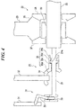
- FIG. 4 illustrates the outboard motor 12 of which the shift state is in the forward state. In the forward state, the drive force generated by the electric motor 17 is not transmitted to the propeller 18 and the drive force from the engine 16 is transmitted to the propeller 18.
- the shift rod 31 of the shift link mechanism 24 moves upward, and it moves the shift slider 21 and the dog clutch 39 axially forward (left direction in the figure) so that the engaged teeth 21a of the shift slider 21 are not engaged with the respective engaging teeth 35d of the motor driven gear 35 and the teeth at the front end of the dog clutch 39 are engaged with the respective teeth on the facing surface of the forward-side driven gear 37.
- the engaged teeth 21a are positioned axially forward of the respective engaging teeth 35d.
- the drive force generated by the engine 16 is transmitted to the propeller shaft 20 via the engine drive shaft 29, the engine drive gear 36, the forward-side driven gear 37, and the dog clutch 39 to rotate the propeller 18 forward. Since in the forward state, the propeller 18 rotates forward, which moves the marine vessel 10 only forward.
- FIG. 5 illustrates the outboard motor 12 of which the shift state is in the reverse state.
- the drive force generated by the electric motor 17 is not transmitted to the propeller 18 and the drive force from the engine 16 is transmitted to the propeller 18.
- the shift rod 31 of the shift link mechanism 24 moves downward, and it moves the shift slider 21 and the dog clutch 39 axially rearward (right direction in the figure) so that the engaged teeth 21a of the shift slider 21 are not engaged with the respective engaging teeth 35d of the motor driven gear 35 and the teeth at the rear end of the dog clutch 39 are engaged with the respective teeth on the facing surface of the reverse-side driven gear 38.
- the engaged teeth 21a are positioned axially rearward of the respective engaging teeth 35d.
- the drive force generated by the engine 16 is transmitted to the propeller shaft 20 via the engine drive shaft 29, the engine drive gear 36, the reverse-side driven gear 38, and the dog clutch 39 to rotate the propeller 18 reversely. Since in the reverse state, the propeller 18 rotates reversely, which moves the marine vessel 10 only reversely.
- FIG. 6 is a diagram explaining signal transmission in a control system for switching drive sources of the outboard motor 12.
- the remote controller 15 transmits to the AHECU 28, in response to an operation on an operation lever 15b by a vessel operator, a shift request that gives an instruction to switch the shift state of the outboard motor 12 to any of the neutral state, the forward state, and the reverse state.
- the remote controller 15 outputs a shift amount of 0% as a shift request in a case of switching the shift state of the outboard motor 12 to the neutral state, outputs a shift amount of 100% as a shift request in a case of switching the shift state of the outboard motor 12 to the forward state, and outputs a shift amount of -100% as a shift request in a case of switching the shift state of the outboard motor 12 to the reverse state.
- the AHECU 28 having received a shift request transfers the shift request to the ECU 27.
- the ECU 27 having received the shift request transmits, to the actuator motor 26, a shift actuator drive signal requesting a drive amount of the actuator motor 26 corresponding to the shift amount indicated by the shift request.
- the actuator motor 26 having received the shift actuator drive signal operates the actuator 25 in accordance with the requested drive amount.
- the actuator 25 includes a shift position sensor (which is not shown), and the shift position sensor detects the position of the shift rod 31 and transmits the detected position as shift position information to the ECU 27 via the actuator motor 26.
- the actuator 25 outputs the shift amount of 0% as shift position information in a case that the shift state of the outboard motor 12 is switched to the neutral state, outputs the shift amount of 100% as shift position information in a case that the shift state of the outboard motor 12 is switched to the forward state, and outputs the shift amount of -100% as shift position information in a case that the shift state of the outboard motor 12 is switched to the reverse state.
- the ECU 27 having received shift position information transfers the shift position information to the AHECU 28.
- the AHECU 28 having received the shift position information determines whether or not the shift amount of the shift position information and the shift amount of the shift request match each other.
- the remote controller 15 includes a semi-cylindrical body 15a and the operation lever 15b movable along the outer periphery of the body 15a, and a plurality of throttle positions of Fmax, F2, F1, N, R1, R2 and Rmax are set clockwise along the circumferential direction of the body 15a.
- the remote controller 15 includes a built-in mechanism that generates click feeling at each throttle position when the operation lever 15b is moved along the outer periphery of the body 15a, and facilitates the movement of the operation lever 15b to a desired throttle position when the vessel operator operates the operation lever 15b.
- Fmax is the maximum power position at which the forward propulsion force of the marine vessel 10 by the propeller 18 becomes maximum.
- Rmax is the maximum power position at which the rearward propulsion force of the marine vessel 10 by the propeller 18 becomes maximum.
- N is the origin position at which the outboard motor 12 generates no propulsion force.
- the region from N to Fmax is a forward region where the outboard motor 12 propels the marine vessel 10 forward, and the region from N to Rmax is a reverse region where the outboard motor 12 propels the marine vessel 10 rearward.
- the operation lever 15b operated by the vessel operator moves from N to Fmax through F1 and F2 in this order.
- the region from N to F1 is an electric motor forward region where the electric motor 17 alone rotates the propeller 18 forward, and in this region, the shift state of the outboard motor 12 becomes the neutral state.
- the region from F1 to F2 is a region where the shift state of the outboard motor 12 is switched from the neutral state to the forward state.
- the region from F2 to Fmax is an engine forward region where the engine 16 alone rotates the propeller 18 forward, and in this region, the shift state of the outboard motor 12 becomes the forward state.
- F1 and F2 may be combined into one throttle position, and when the operation lever 15b moves to the throttle position, the shift state of the outboard motor 12 may be switched from the neutral state to the forward state.
- the operation lever 15b moves from N to Rmax through R1 and R2 in this order.
- the region from N to R1 is an electric motor reverse region where the electric motor 17 alone rotates the propeller 18 reversely, and also in this region, the shift state of the outboard motor 12 becomes the neutral state.
- the region from R1 to R2 is a region where the shift state of the outboard motor 12 is switched from the neutral state to the reverse state.
- the region from R2 to Rmax is an engine reverse region where the engine 16 alone rotates the propeller 18 reversely, and also in this region, the shift state of the outboard motor 12 becomes the reverse state.
- R1 and R2 may be combined into one throttle position, and when the operation lever 15b moves to the throttle position, the shift state of the outboard motor 12 may be switched from the neutral state to the reverse state.
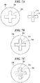
- FIGS. 7A to 7C are views explaining the workings of the outboard motor 12 to switch its shift state from the forward state or the reverse state to the neutral state, and each illustrates cross sections of the motor driven gear 35 and the shift slider 21. Referring to FIGS. 7A to 7C , a description is given of a situation that the shift state is not smoothly switched. In FIGS. 7A to 7C , for easy understanding, the engaging teeth 35d of the motor driven gear 35 and the engaged teeth 21a of the shift slider 21 are drawn largely in an exaggerated manner.
- FIG. 7A for example, four engaging teeth 35d project toward the space 35c of the body 35b of the motor driven gear 35, and, for example, four engaged teeth 21a project from the periphery of the shift slider 21.
- the motor driven gear 35 and the shift slider 21 having such configurations, in order to switch the shift state of the outboard motor 12 from the forward state or the reverse state to the neutral state, as illustrated in FIG. 7B , it is necessary for the engaged teeth 21a to enter the respective engaging grooves 35e each formed between two adjacent engaging teeth 35d.
- FIG. 7B and FIG. 7C described later, the shift slider 21 and the engaged teeth 21a are indicated by broken lines.
- the switching of the shift state is temporarily interrupted in a case that the shift state is not smoothly switched. That is, in a case of failure in switching the drive source to be used between the engine 16 and the electric motor 17, the AHECU 28 temporarily interrupts the switching between the drive sources. After having temporarily interrupted the switching between the drive sources, the AHECU 28 may attempt the switching between the drive sources again.
- the AHECU 28 moves the shift slider 21 at a predetermined position (first position) where the shift slider 21 is not engaged with the motor driven gear 35, in the axial direction of the propeller shaft 20 toward the motor driven gear 35, the AHECU 28 moves back the shift slider 21 in the direction of the first position when the shift slider 21 fails to be engaged with the motor driven gear 35.
- the AHECU 28 moves the dog clutch 39 at another predetermined position (second position) where the dog clutch 39 is not engaged with the forward-side driven gear 37 or the reverse-side driven gear 38, in the axial direction of the propeller shaft 20 toward the forward-side driven gear 37 or the reverse-side driven gear 38, the AHECU 28 moves back the dog clutch 39 in the direction of the second position when the dog clutch 39 fails to be engaged with the forward-side driven gear 37 or the reverse-side driven gear 38.
- the AHECU 28 moves the shift slider 21 that is not engaged with the motor driven gear 35, in the axial direction of the propeller shaft 20 from the first position toward the first driving member, the AHECU 28 brings, by the electric motor 17, the number or revolutions (hereinafter, referred to as a rotation speed) of the motor driven gear 35 close to the rotation speed of the shift slider 21.
- the engine 16 may rotate the shift slider 21 via the forward-side driven gear 37, the reverse-side driven gear 38, the dog clutch 39, and the propeller shaft 20, and the engine 16 may be brought into an idle state.
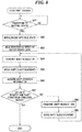
- FIG. 8 is a flowchart of the first shift change processing using a method of switching the drive sources of the marine propulsion device according to the present embodiment.
- the processing illustrated in FIG. 8 is carried out by the AHECU 28 executing a control program stored in advance in a memory or a non-transitory computer readable medium (which is not shown) when switching the shift state of the outboard motor 12 from the forward state to the neutral state.
- the AHECU 28 determines whether or not the operation lever 15b has been moved from F2 to F1 to request a transition of the shift state of the outboard motor 12 from the forward state to the neutral state (Step S81).
- step S81 if the transition from the forward state to the neutral state is not requested, the processing returns to step S81, and the AHECU 28 continues the determination.
- the AHECU 28 first brings the engine 16 into the idle state (Step S82).
- the remote controller 15 transmits a shift amount of 0% as a shift request to the AHECU 28.
- the AHECU 28 uses the electric motor 17 to adjust the rotation speed of the motor driven gear 35 rotated by the electric motor 17 so as to substantially match the rotation speed of the shift slider 21 rotated by the engine 16 via the engine-side clutch mechanism 22 and the propeller shaft 20 (Step S83).
- the AHECU 28 brings the rotation speed of the motor driven gear 35 close to the rotation speed of the shift slider 21, but does not cause the rotation speed of the motor driven gear 35 to completely match the rotation speed of the shift slider 21.
- the AHECU 28 transmits, to the ECU 27 the shift request (shift amount of 0%) transmitted from the remote controller 15 (Step S84), and the ECU 27 causes the shift link mechanism 24 to move the shift slider 21 axially rearward (Step S85).
- the shift state of the outboard motor 12 attempts to change from the forward state illustrated in FIG. 4 to the neutral state illustrated in FIG. 3 .
- the ECU 27 acquires shift position information indicating the position of the shift rod 31 detected by the actuator 25 (Step S86).
- the actuator 25 outputs the shift amount of 0% in a case that the shift state of the outboard motor 12 is successfully switched to the neutral state, and outputs the shift amount of 50% in a case that the engaged teeth 21a of the shift slider 21 fail to enter the respective engaging grooves 35e of the motor driven gear 35 and the shift state of the outboard motor 12 is not switched to the neutral state, as described in FIGS. 7A to 7C .
- the actuator 25 may output any of the following as the shift position information, rather than outputting uniformly the shift amount of 50% as the shift position information.
- the actuator 25 may output the progress rate corresponding to the actual operation amount of the actuator 25, the actual movement amount of the shift rod 31, or the actual movement amount of the shift slider 21 (e.g., 25% as a progress rate when the actuator 25 is operated only 25% of the rated operation amount).
- the ECU 27 then transfers the acquired shift position information to the AHECU 28, and the AHECU 28 having received the shift position information determines whether or not the shift amount of the shift request matches the shift amount of the shift position information (Step S87).
- step S87 if the shift amount of the shift request and the shift amount of the shift position information are both 0% and thus match each other, the AHECU 28 ends the present processing on an assumption that the shift state of the outboard motor 12 has been switched to the neutral state. On the other hand, if the shift amount of the shift position information is not 0% and the shift amount of the shift request and the shift amount of the shift position information do not match each other, the AHECU 28 transmits a shift amount of 100% as a shift request to the ECU 27 on an assumption that the shift state of the outboard motor 12 has not successfully switched to the neutral state (Step S88).
- the ECU 27 having received the shift request uses the shift link mechanism 24 to temporarily interrupt the axially rearward movement of the shift slider 21 and move the shift slider 21 axially forward (Step S89).
- the shift state of the outboard motor 12 returns to the forward state illustrated in FIG. 4 , and the shift slider 21 (in particular, the engaged teeth 21a) moves back in the direction of the movement start position (first position) at which the movement is started in step S85. That is, the switching of the shift state of the outboard motor 12 from the forward state to the neutral state is temporarily interrupted.
- step S89 the processing returns to step S84, where the AHECU 28 transmits, to the ECU 27, the shift request (shift amount of 0%) having been transmitted from the remote controller 15, and moves the shift slider 21 axially rearward again to attempt to switch the shift state of the outboard motor 12 from the forward state to the neutral state. That is, the series of processing of steps S84, S85, S86, S87 (NO), S88, and S89 is repeated unless the shift state of the outboard motor 12 is successfully switched to the neutral state.
- the rotation speed of the motor driven gear 35 and the rotation speed of the shift slider 21 do not completely match each other, which changes the relative position between the engaged tooth 21a and the corresponding engaging groove 35e with the lapse of time.
- the engaged teeth 21a can smoothly enter the respective engaging grooves 35e eventually. Therefore, by repeating the series of processing in steps S84, S85, S86, S87 (NO), S88, and S89, the engaged teeth 21a are allowed to smoothly enter the corresponding engaging grooves 35e, and as a result, the AHECU 28 smoothly switches the shift state of the outboard motor 12 from the forward state to the neutral state.
- the processing may return to step S84 after a certain period of delay time has elapsed after step S89 (i.e., the AHECU 28 may cause the shift slider 21 to move toward the motor driven gear 35 again after a certain period of delay time has elapsed), so as to intentionally change the relative position between the engaged teeth 21a and the respective engaging grooves 35e at time when the shift slider 21 meets the motor driven gear 35 and thus increase the possibility that the engaged teeth 21a smoothly enter the respective engaging grooves 35e.
- the processing may return to step S84 after a certain period of delay time has elapsed after step S89 (i.e., the AHECU 28 may cause the shift slider 21 to move toward the motor driven gear 35 again after a certain period of delay time has elapsed), so as to intentionally change the relative position between the engaged teeth 21a and the respective engaging grooves 35e at time when the shift slider 21 meets the motor driven gear 35 and thus increase the possibility that the engaged teeth 21a smoothly enter the respective engaging grooves 35e.
- FIG. 9 is a flowchart of the second shift change processing using a method of switching the drive sources of the marine propulsion device according to the present embodiment.
- the processing illustrated in FIG. 9 is carried out by the AHECU 28 executing a control program stored in advance in a memory or a non-transitory computer readable medium (which is not shown) when switching the shift state of the outboard motor 12 from the neutral state to the forward state.
- the AHECU 28 determines whether or not the operation lever 15b has been moved from F1 to F2 to request a transition of the shift state of the outboard motor 12 from the neutral state to the forward state (Step S91).
- step S91 if the transition from the neutral state to the forward state is not requested, the processing returns to step S91, and the AHECU 28 continues the determination.
- the AHECU 28 first brings the engine 16 into the idle state (Step S92).
- the remote controller 15 transmits a shift amount of 100% as a shift request to the AHECU 28.
- the AHECU 28 uses the electric motor 17 to adjust the rotation speed of the dog clutch 39 rotated by the electric motor 17 via the electric motor-side clutch mechanism 23, the shift slider 21, and the propeller shaft 20 so as to substantially match the rotation speed of the forward-side driven gear 37 rotated by the engine 16 (Step S93).
- the AHECU 28 brings the rotation speed of the dog clutch 39 close to the rotation speed of the forward-side driven gear 37, but does not cause the rotation speed of the dog clutch 39 to completely match the rotation speed of the forward-side driven gear 37.
- the AHECU 28 transmits, to the ECU 27 the shift request (shift amount of 100%) transmitted from the remote controller 15 (Step S94), and the ECU 27 causes the shift link mechanism 24 to move the dog clutch 39 axially forward (Step S95).
- the shift state of the outboard motor 12 attempts to change from the neutral state illustrated in FIG. 3 to the forward state illustrated in FIG. 4 .
- the ECU 27 acquires shift position information indicating the position of the shift rod 31 detected by the actuator 25 (Step S96).
- the actuator 25 outputs the shift amount of 100% in a case that the shift state of the outboard motor 12 is successfully switched to the forward state, and outputs the shift amount of 50% in a case that the teeth of the front end of the dog clutch 39 fail to enter the respective grooves each formed between the teeth of the facing surface of the forward-side driven gear 37 and the shift state of the outboard motor 12 is not switched to the forward state, as described above.
- the actuator 25 may output, as the shift position information, the progress rate corresponding to the actual operation amount of the actuator 25, for example.
- the ECU 27 then transfers the acquired shift position information to the AHECU 28, and the AHECU 28 having received the shift position information determines whether or not the shift amount of the shift request matches the shift amount of the shift position information (Step S97).
- step S97 if the shift amount of the shift request and the shift amount of the shift position information are both 100% and thus match each other, the AHECU 28 ends the present processing on an assumption that the shift state of the outboard motor 12 has been switched to the forward state. On the other hand, if the shift amount of the shift position information is not 100% and the shift amount of the shift request and the shift amount of the shift position information do not match each other, the AHECU 28 transmits a shift amount of 0% as a shift request to the ECU 27 on an assumption that the shift state of the outboard motor 12 has not successfully switched to the forward state (Step S98).
- the ECU 27 having received the shift request uses the shift link mechanism 24 to temporarily interrupt the axially forward movement of the dog clutch 39 and move the dog clutch 39 axially rearward (Step S99).
- the shift state of the outboard motor 12 returns to the neutral state illustrated in FIG. 3 , and the dog clutch 39 moves back in the direction of the movement start position (second position) at which the movement is started in step S95. That is, the switching of the shift state of the outboard motor 12 from the neutral state to the forward state is temporarily interrupted.
- step S99 the processing returns to step S94, where the AHECU 28 transmits, to the ECU 27, the shift request (shift amount of 100%) having been transmitted from the remote controller 15, and moves the dog clutch 39 axially forward again to attempt to switch the shift state of the outboard motor 12 from the neutral state to the forward state. That is, the series of processing of steps S94, S95, S96, S97 (NO), S98, and S99 is repeated unless the shift state of the outboard motor 12 is successfully switched to the forward state.
- the rotation speed of the dog clutch 39 does not completely match the rotation speed of the forward-side driven gear 37, which changes the relative position between the teeth of the front end of the dog clutch 39 and the corresponding grooves each formed between the teeth of the facing surface of the forward-side driven gear 37 with the lapse of time. Accordingly, when the ECU 27 moves the dog clutch 39 axially forward again, the teeth of the front end of the dog clutch 39 can smoothly enter the respective groove each formed between the teeth of the facing surface of the forward-side driven gear 37 eventually.
- the processing may return to step S94 after a certain period of delay time has elapsed after step S99 (i.e., the AHECU 28 may cause the dog clutch 39 to move toward the forward-side driven gear 37 again after a certain period of delay time has elapsed), so as to intentionally change the relative position between the teeth of the front end of the dog clutch 39 and the respective grooves each formed between the teeth of the facing surface of the forward-side driven gear 37 at time when the dog clutch 39 meets the forward-side driven gear 37 and thus increase the possibility that the teeth of the front end of the dog clutch 39 smoothly enter the respective grooves each formed between the teeth of the facing surface of the forward-side driven gear 37.
- this process it is similarly expected to reduce the number of repetitions of the series of processing described above, and it is thus possible to suppress the harness connected to the actuator motor 26 from generating heat.
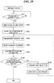
- FIG. 10 is a flowchart of the third shift change processing using a method of switching the drive sources of the marine propulsion device according to the present embodiment.
- the processing illustrated in FIG. 10 is carried out by the AHECU 28 executing a control program stored in advance in a memory or a non-transitory computer readable medium (which is not shown) when switching the shift state of the outboard motor 12 from the neutral state to the reverse state.
- the AHECU 28 determines whether or not the operation lever 15b has been moved from R1 to R2 to request a transition of the shift state of the outboard motor 12 from the neutral state to the reverse state (Step S101).
- step S101 if the transition from the neutral state to the reverse state is not requested, the processing returns to step S101, and the AHECU 28 continues the determination.
- the AHECU 28 first brings the engine 16 into the idle state (Step S102).
- the remote controller 15 transmits a shift amount of -100% as a shift request to the AHECU 28.
- the AHECU 28 uses the electric motor 17 to adjust the rotation speed of the dog clutch 39 rotated by the electric motor 17 via the electric motor-side clutch mechanism 23, the shift slider 21, and the propeller shaft 20 so as to substantially match the rotation speed of the reverse-side driven gear 38 rotated by the engine 16 (Step S103).
- the AHECU 28 brings the rotation speed of the dog clutch 39 close to the rotation speed of the reverse-side driven gear 38, but does not cause the rotation speed of the dog clutch 39 to completely match the rotation speed of the reverse-side driven gear 38.
- the AHECU 28 transmits, to the ECU 27 the shift request (shift amount of -100%) transmitted from the remote controller 15 (Step S104), and the ECU 27 causes the shift link mechanism 24 to move the dog clutch 39 axially rearward (Step S105).
- the shift state of the outboard motor 12 attempts to change from the neutral state illustrated in FIG. 3 to the reverse state illustrated in FIG. 5 .
- the ECU 27 acquires shift position information indicating the position of the shift rod 31 detected by the actuator 25 (Step S106).
- the actuator 25 outputs the shift amount of -100% in a case that the shift state of the outboard motor 12 is successfully switched to the reverse state, and outputs the shift amount of -50% in a case that the teeth of the rear end of the dog clutch 39 fail to enter the respective grooves each formed between the teeth of the facing surface of the reverse-side driven gear 38 and the shift state of the outboard motor 12 is not switched to the reverse state, as described above.
- the actuator 25 may output, as the shift position information, the progress rate corresponding to the actual operation amount of the actuator 25, for example.
- the ECU 27 then transfers the acquired shift position information to the AHECU 28, and the AHECU 28 having received the shift position information determines whether or not the shift amount of the shift request matches the shift amount of the shift position information (Step S107).
- step S107 if the shift amount of the shift request and the shift amount of the shift position information are both -100% and thus match each other, the AHECU 28 ends the present processing on an assumption that the shift state of the outboard motor 12 has been switched to the reverse state. On the other hand, if the shift amount of the shift position information is not -100% and the shift amount of the shift request and the shift amount of the shift position information do not match each other, the AHECU 28 transmits a shift amount of 0% as a shift request to the ECU 27 on an assumption that the shift state of the outboard motor 12 has not successfully switched to the reverse state (Step S108).
- the ECU 27 having received the shift request uses the shift link mechanism 24 to temporarily interrupt the axially rearward movement of the dog clutch 39 and move the dog clutch 39 axially forward (Step S109).
- the shift state of the outboard motor 12 returns to the reverse state illustrated in FIG. 5 , and the dog clutch 39 moves back in the direction of the movement start position (second position) at which the movement is started in step S105. That is, the switching of the shift state of the outboard motor 12 from the neutral state to the reverse state is temporarily interrupted.
- step S109 the processing returns to step S104, where the AHECU 28 transmits, to the ECU 27, the shift request (shift amount of -100%) having been transmitted from the remote controller 15, and moves the dog clutch 39 axially rearward again to attempt to switch the shift state of the outboard motor 12 from the neutral state to the reverse state. That is, the series of processing of steps S104, S105, S106, S107 (NO), S108, and S109 is repeated unless the shift state of the outboard motor 12 is successfully switched to the reverse state.
- the rotation speed of the dog clutch 39 does not completely match the rotation speed of the reverse-side driven gear 38, which changes the relative position between the teeth of the rear end of the dog clutch 39 and the corresponding grooves each formed between the teeth of the facing surface of the reverse-side driven gear 38 with the lapse of time. Accordingly, when the ECU 27 moves the dog clutch 39 axially rearward again, the teeth of the rear end of the dog clutch 39 can smoothly enter the respective grooves each formed between the teeth of the facing surface of the reverse-side driven gear 38 eventually.
- the processing may return to step S104 after a certain period of delay time has elapsed after step S109 (i.e., the AHECU 28 may cause the dog clutch 39 to move toward the reverse-side driven gear 38 again after a certain period of delay time has elapsed), so as to intentionally change the relative position between the teeth of the rear end of the dog clutch 39 and the respective grooves each formed between the teeth of the facing surface of the reverse-side driven gear 38 at time when the dog clutch 39 meets the reverse-side driven gear 38 and thus increase the possibility that the teeth of the rear end of the dog clutch 39 smoothly enter the respective grooves each formed between the teeth of the facing surface of the reverse-side driven gear 38.
- this process it is similarly expected to reduce the number of repetitions of the series of processing described above, and it is thus possible to suppress the harness connected to the actuator motor 26 from generating heat.
- FIG. 11 is a flowchart of the fourth shift change processing using a method of switching the drive sources of the marine propulsion device according to the present embodiment.
- the processing of FIG. 11 is carried out by the AHECU 28 executing a control program stored in advance in a memory or a non-transitory computer readable medium (which is not shown) when switching the shift state of the outboard motor 12 from the reverse state to the neutral state.
- the AHECU 28 determines whether or not the operation lever 15b has been moved from R2 to R1 to request a transition of the shift state of the outboard motor 12 from the reverse state to the neutral state (Step S111).
- step S111 if the transition from the reverse state to the neutral state is not requested, the processing returns to step S111, and the AHECU 28 continues the determination.
- the AHECU 28 first brings the engine 16 into the idle state (Step S112).
- the remote controller 15 transmits a shift amount of 0% as a shift request to the AHECU 28.
- the AHECU 28 uses the electric motor 17 to adjust the rotation speed of the motor driven gear 35 rotated by the electric motor 17 so as to substantially match the rotation speed of the shift slider 21 rotated by the engine 16 via the engine-side clutch mechanism 22 and the propeller shaft 20 (Step S113).
- the AHECU 28 brings the rotation speed of the motor driven gear 35 close to the rotation speed of the shift slider 21, but does not cause the rotation speed of the motor driven gear 35 to completely match the rotation speed of the shift slider 21.
- the AHECU 28 transmits, to the ECU 27 the shift request (shift amount of 0%) transmitted from the remote controller 15 (Step S114), and the ECU 27 causes the shift link mechanism 24 to move the shift slider 21 axially forward (Step S115).
- the shift state of the outboard motor 12 attempts to change from the reverse state illustrated in FIG. 5 to the neutral state illustrated in FIG. 3 .
- the ECU 27 acquires shift position information indicating the position of the shift rod 31 detected by the actuator 25 (Step S116).
- the actuator 25 outputs the shift amount of 0% in a case that the shift state of the outboard motor 12 is successfully switched to the neutral state, and outputs the shift amount of -50% in a case that the shift state of the outboard motor 12 is not switched from the reverse state to the neutral state.
- the actuator 25 may output, as the shift position information, the progress rate corresponding to the actual operation amount of the actuator 25, for example.
- the ECU 27 then transfers the acquired shift position information to the AHECU 28, and the AHECU 28 having received the shift position information determines whether or not the shift amount of the shift request matches the shift amount of the shift position information (Step S117).
- step S117 if the shift amount of the shift request and the shift amount of the shift position information are both 0% and thus match each other, the AHECU 28 ends the present processing on an assumption that the shift state of the outboard motor 12 has been switched to the neutral state. On the other hand, if the shift amount of the shift position information is not 0% and the shift amount of the shift request and the shift amount of the shift position information do not match each other, the AHECU 28 transmits a shift amount of -100% as a shift request to the ECU 27 on an assumption that the shift state of the outboard motor 12 has not successfully switched to the neutral state (Step S118).
- the ECU 27 having received the shift request uses the shift link mechanism 24 to temporarily interrupt the axially forward movement of the shift slider 21 and move the shift slider 21 axially rearward (Step S119).
- the shift state of the outboard motor 12 returns to the reverse state illustrated in FIG. 5 , and the shift slider 21 moves back in the direction of the movement start position (first position) at which the movement is started in step S115. That is, the switching of the shift state of the outboard motor 12 from the reverse state to the neutral state is temporarily interrupted.
- step S119 the processing returns to step S114, where the AHECU 28 transmits, to the ECU 27, the shift request (shift amount of 0%) having been transmitted from the remote controller 15, and moves the shift slider 21 axially forward again to attempt to switch the shift state of the outboard motor 12 from the reverse state to the neutral state. That is, the series of processing of steps S114, S115, S116, S117 (NO), S118, and S119 is repeated unless the shift state of the outboard motor 12 is successfully switched to the neutral state.
- the rotation speed of the motor driven gear 35 and the rotation speed of the shift slider 21 do not completely match each other, which changes the relative position between the engaged teeth 21a and the corresponding engaging grooves 35e with the lapse of time.
- the engaged teeth 21a can smoothly enter the respective engaging grooves 35e eventually. Therefore, by repeating the series of processing in steps S114, S115, S116, S117 (NO), S118, and S119, the engaged teeth 21a are allowed to smoothly enter the respective engaging grooves 35e, and as a result, the AHECU 28 smoothly switches the shift state of the outboard motor 12 from the reverse state to the neutral state.
- the processing may return to step S114 after a certain period of delay time has elapsed after step S119 (i.e., the AHECU 28 may cause the shift slider 21 to move toward the motor driven gear 35 again after a certain period of delay time has elapsed), so as to intentionally change the relative position between the engaged teeth 21a and the respective engaging grooves 35e at time when the shift slider 21 meets the motor driven gear 35 and thus increase the possibility that the engaged teeth 21a smoothly enter the respective engaging grooves 35e.
- the AHECU 28 may cause the shift slider 21 to move toward the motor driven gear 35 again after a certain period of delay time has elapsed
- the AHECU 28 when switching the shift state of the outboard motor 12, the AHECU 28 brings the engine 16 into the idle state.
- the rotation speed of the engine 16 at the time of switching the shift state is not limited to the rotation speed of idling and can be determined freely as far as the rotation speed of the motor driven gear 35 rotated by the electric motor 17 is adjusted so as to substantially match the rotation speed of the shift slider 21 rotated by the engine 16 or the rotation speed of the dog clutch 39 rotated by the electric motor 17 is adjusted so as to substantially match the rotation speed of the forward-side driven gear 37 or the reverse-side driven gear 38 rotated by the engine 16.
- the AHECU 28 interrupts switching of the shift state temporarily (for a predetermined period of time) in a case that the switching of the shift state is not smoothly performed in all of the switching of the shift state from the neutral state to the forward state, the switching of the shift state from the neutral state to the reverse state, the switching of the shift state from the forward state to the neutral state, and the switching of the shift state from the reverse state to the neutral state.
- the AHECU 28 may omit temporary interruption (interruption for the predetermined period of time) of the switching of the shift state in the switching of the shift state where the edge of each tooth to be engaged is tapered to easily mesh.
- marine propulsion devices to which the present teaching is applicable is not limited to outboard motors, and the present teaching is also applicable to inboard/outboard motors (stern drive, inboard motor/outboard drive) and inboard motors having a mechanism that switches between an engine and an electric motor as a drive source.
Landscapes
- Chemical & Material Sciences (AREA)
- Engineering & Computer Science (AREA)
- Combustion & Propulsion (AREA)
- Mechanical Engineering (AREA)
- Ocean & Marine Engineering (AREA)
- Gear-Shifting Mechanisms (AREA)
- Mechanical Operated Clutches (AREA)
- Control Of Transmission Device (AREA)
Abstract
Description
- The present invention relates to drive source switching systems that comprises a drive source switching mechanism that is configured to switch, between a first drive source and a second drive source of a marine propulsion device, and method of switching drive sources of the marine propulsion device.
- In recent years, marine propulsion devices each including an electric motor and an internal combustion engine as its drive sources have been known. The use of an electric motor for a drive source of a marine propulsion device, makes speed control of a marine vessel easier at very low speed, and it is suitable for correcting the position of a hull moved due to wind or waves e.g. in fishing.
- Such a marine propulsion device switches its drive source from an internal combustion engine to an electric motor, by moving a shift slider coupled to a propeller shaft, in the axial direction of the propeller shaft, and then meshing protrusions (teeth) provided on the shift slider with a gear (hereinafter, referred to as a "motor driven gear") driven by the electric motor. It is disclosed in, for example,
JP 2017-218016 A - It has been proposed typically to install, in a mechanism that meshes protrusions (teeth) with a gear, a synchronizing mechanism for synchronizing the number of revolutions of the protrusions with the number of revolutions of the gear to be meshed, so that the protrusions and the gear can smoothly mesh with each other.
- When an electric motor is retrofitted into a marine propulsion device, it is sometimes difficult to install the synchronization mechanism in the marine propulsion device together with the electric motor, because there is not enough space in the marine propulsion device. The retrofit of an electric motor needs miniaturization of the protrusions provided on the shift slider and the motor driven gear, and it is also difficult to apply taper processing that facilitates meshing to the edges of the protrusions and the edge of the motor driven gear, from the viewpoint of securing their strength.
- As a result, when the protrusions provided on the shift slider mesh with the motor driven gear, an abnormal noise may be generated by collision between the protrusions and the motor driven gear. In some cases, because of unsuccessful meshing between the protrusions and the gear, the actuator that moves the shift slider continues to move the shift slider for a series of attempts to mesh the protrusions and the motor driven gear, resulting in applying a large load to the drive motor of the actuator. That is, there is still room for improvement in marine propulsion devices including an electric motor together with an internal combustion engine as their drive sources, in terms of switching the drive sources.
- It is the object of the present invention to provide a drive source switching system that comprises a drive source switching mechanism that is configured to switch, between a first drive source and a second drive source of a marine propulsion device, and method of switching drive sources of the marine propulsion device, which enable smooth switching of the drive sources.
- According to the present invention said object is solved by a drive source switching system that comprises a drive source switching mechanism that is configured to switch, between a first drive source and a second drive source of a marine propulsion device having the features of independent claim 1. Moreover, according to the present invention said object is solved by method of switching drive sources of the marine propulsion device having the features of
independent claim 17. Preferred embodiments are laid down in the dependent claims. - According to an embodiment of the present teaching, a drive source switching system for a marine propulsion device, comprises a first drive source, a second drive source, and a propeller shaft that rotates blades to generate a propulsive force. The drive source switching system further comprises a first driving member that transmits a drive force generated by the first drive source, and a second driving member that transmits a drive force generated by the second drive source. The drive source switching system further comprises a first driven member that is movable in an axial direction of the propeller shaft, engageably with the first driving member, and a second driven member that is movable in the axial direction of the propeller shaft, engageably with the second driving member. The drive source switching system further comprises a controller configured or programmed to control a movement of the first driven member. The first driven member transmits the drive force generated by the first drive source to the propeller shaft when engaged with the first driving member. The second driven member transmits a drive force generated by the second drive source to the propeller shaft when engaged with the second driving member. In a case that the controller moves the first driven member at a first position where the first driven member is not engaged with the first driving member, in the axial direction of the propeller shaft toward the first driving member, the controller moves back the first driven member in a direction of the first position when the first driven member fails to be engaged with the first driving member. The controller may move the first driven member toward the first driving member again after the failure.
- According to another embodiment of the present teaching, a drive source switching system for a marine propulsion device, comprises a first drive source, a second drive source, and a propeller shaft that rotates blades to generate a propulsive force. The drive source switching system further comprises a drive source switching mechanism that switches, between the first drive source and the second drive source, a drive source that generates a drive force to be transmitted to the propeller shaft. The drive source switching system further comprises a controller configured or programmed to control the drive source switching mechanism to switch the drive source between the first drive source and the second drive source. When switching the drive source between the first drive source and the second drive source is failed, the controller temporarily interrupts the switching the drive source between the first drive source and the second drive source. The controller may attempt the switching between the first drive source and the second drive source again after the failure.
- According to another embodiment of the present teaching, a marine propulsion device includes a first drive source, a second drive source, a propeller shaft that rotates blades to generate a propulsive force, a drive source switching mechanism that switches, between the first drive source and the second drive source, a drive source that generates a drive force to be transmitted to the propeller shaft, and a controller. A method of switching drive sources of the marine propulsion device comprises controlling, by the controller, the drive source switching mechanism to switch the drive source between the first drive source and the second drive source, and when switching the drive source between the first drive source and the second drive source is failed, temporarily interrupting, by the controller, switching the drive source between the first drive source and the second drive source.
- According to an embodiment of the present teaching, the controller moves back the first driven member to the direction of the first position when the first driven member fails to be engaged with the first driving member, or, the controller temporarily interrupts the switching between the first drive source and the second drive source when the controller fails to switch between these drive sources. It reduces impossible attempts to switch between the drive sources, resulting in smooth switching of the drive sources.
- Further features of the present teaching will become apparent from the following description of preferred embodiments with reference to the attached drawings.
- The above and other elements, features, steps, characteristics and advantages of the present teaching will become more apparent from the following detailed description of the preferred embodiments with reference to the attached drawings.
-
-
FIG. 1 is a side view of a marine vessel to which a drive source switching system for a marine propulsion device according to an embodiment of the present teaching is provided. -
FIG. 2 is a diagram schematically illustrating a configuration of an outboard motor inFIG. 1 . -
FIG. 3 is a view for explaining the outboard motor the shift state of which is in a neutral state. -
FIG. 4 is a view for explaining the outboard motor the shift state of which is in a forward state. -
FIG. 5 is a view for explaining the outboard motor the shift state of which is in a reverse state. -
FIG. 6 is a diagram explaining signal transmission in a control system for switching drive sources of the outboard motor. -
FIGS. 7A to 7C are views explaining the workings of the outboard motor to switch its shift state from the forward state or the reverse state to the neutral state. -
FIG. 8 is a flowchart illustrating first shift change processing. -
FIG. 9 is a flowchart illustrating second shift change processing. -
FIG. 10 is a flowchart illustrating third shift change processing. -
FIG. 11 is a flowchart illustrating fourth shift change processing. - Hereinafter, preferred embodiments of the present teaching will be described with reference to the drawings.
-
FIG. 1 is a side view of a marine vessel to which a drive source switching system for a marine propulsion device according to an embodiment of the present teaching is provided. Thismarine vessel 10 is a planing boat, and includes ahull 11, a plurality ofoutboard motors 12 which define and function as marine propulsion devices mounted on thehull 11, and a plurality oftrim tabs 13. Asteering wheel 14 and aremote controller 15 which will be described later are provided in the vicinity of a cockpit in thehull 11. - The
outboard motors 12 are mounted on a stern of thehull 11 side by side. Each of theoutboard motors 12 includes two drive sources. One is an engine 16 (a second drive source), which is, e.g., an internal combustion engine, and the other is an electric motor 17 (a first drive source). Theoutboard motors 12 each generates a propulsive force to move thehull 11 by using a propeller 18 (or blades to generate a propulsive force) that is rotatable by a driving force generated by theengine 16 or theelectric motor 17. - Each of the
outboard motors 12 is mounted on thehull 11 via amounting unit 19 such that it is able to turn about a substantially vertical steering axis in themounting unit 19 in response to a vessel operator's operation of thesteering wheel 14. With theoutboard motors 12 turning in response to the operation of thesteering wheel 14, themarine vessel 10 is steered.Trim tabs 13 are mounted on the stern on the port side and the starboard side such that they are able to swing about a substantially horizontal swing axis in the stern. Thetrim tabs 13 swinging about the swing axis adjust the lift generated at the stern of thehull 11 to control the posture of thehull 11. -
FIG. 2 is a diagram schematically illustrating the configuration of one of theoutboard motors 12 inFIG. 1 . The diagram mainly illustrates theengine 16, theelectric motor 17 and the control system for switching the drive sources of theoutboard motor 12 for explanation purposes, and the control systems for controlling drive forces generated by the drive sources are omitted. - The
outboard motor 12 includes theengine 16, theelectric motor 17, and apropeller shaft 20. Thepropeller 18 is connected to thepropeller shaft 20 and thepropeller shaft 20 rotates thepropeller 18 to generate a propulsive force. Theoutboard motor 12 further includes a shaft-like shift slider 21 (first driven member) coupled to thepropeller shaft 20. Theshift slider 21 is not necessarily disposed coaxially with thepropeller shaft 20. Theshift slider 21 is only required to be disposed at a position movable by ashift link mechanism 24 along the rotation axis of thepropeller shaft 20. - The
outboard motor 12 further includes an engine-sideclutch mechanism 22 and an electric motor-sideclutch mechanism 23 that form a drive source switching mechanism. The engine-sideclutch mechanism 22 switches transmission and non-transmission of the drive force from theengine 16 to thepropeller shaft 20. The electric motor-sideclutch mechanism 23 switches transmission and non-transmission of the drive force from theelectric motor 17 to theshift slider 21. Theoutboard motor 12 further includes the shift link mechanism 24 (movement mechanism), anactuator 25 that moves theshift link mechanism 24, and anactuator motor 26 which is, e.g., an electric motor that operates theactuator 25. Theshift link mechanism 24 is driven by the electric motor and moves theshift slider 21 or adog clutch 39 which will be described later, in the axial direction of thepropeller shaft 20. In the present embodiment, the axial direction of theshift slider 21 and thepropeller shaft 20 will hereinafter be referred to simply as "axially" or "the axial direction". - The
outboard motor 12 further includes anECU 27 that transmits a drive signal (shift actuator drive signal) to theactuator motor 26, and an actuator head (AH) ECU 28 (controller) that requests theECU 27 to switch the drive forces in response to an input from theremote controller 15. Theengine 16 and the engine-sideclutch mechanism 22 are connected by anengine drive shaft 29, and theelectric motor 17 and the electric motor-sideclutch mechanism 23 are connected by amotor drive shaft 30. - In the
shift link mechanism 24, theactuator 25 moves up and down ashift rod 31 that is connected to one end of an L-shapedlink arm 32, and a tip of theshift slider 21 is connected to the other end of thelink arm 32 via apusher 33. Thelink arm 32 moves theshift slider 21 in the axial direction by converting the up and down movement of theshift rod 31 into the back and forth movement of thepusher 33. Thus, theshift slider 21 moves in the axial direction of the shift slider 21 (and the propeller shaft 20) engageably with a motor drivengear 35 which will be described later. It should be noted that theactuator 25 may be one that moves theshift rod 31 up and down by using the hydraulic pressure generated by the operation of theactuator motor 26, or one that mechanically converts the rotation of theactuator motor 26 to the up and down movement of theshift rod 31 by a ball screw. - The
AHECU 28 controls the movement of theshift slider 21 at least, and preferably further controls the movement of a forward-side drivengear 37 and a reverse-side drivengear 38 described later, thereby controlling the switching between theengine 16 and theelectric motor 17 by the engine-sideclutch mechanism 22 and the electric motor-sideclutch mechanism 23. -
FIGS. 3 to 5 are enlarged partial views for explaining the configurations of the engine-sideclutch mechanism 22, the electric motor-sideclutch mechanism 23 and theshift link mechanism 24 illustrated inFIG. 2 . - The electric motor-side
clutch mechanism 23 includes amotor drive gear 34, a motor driven gear 35 (first driving member) and a plurality of protrusive engagedteeth 21a. Themotor drive gear 34 is a bevel gear that is fixed to the lower end of themotor drive shaft 30 in the figure and is rotatable together with themotor drive shaft 30. The motor driven gear 35 (first driving member) is disposed so as to cover theshift slider 21. The protrusive engagedteeth 21a are disposed at equal intervals along the outer periphery of theshift slider 21. The motor drivengear 35 is a member that transmits the drive force generated by theelectric motor 17, and includes abevel gear portion 35a and a substantiallycylindrical body 35b. Thebody 35b has aspace 35c inside thereof. Thespace 35c accommodates the engagedteeth 21a of theshift slider 21 and extends in the axial direction so that the engagedteeth 21a can move in the axial direction. A plurality of engagingteeth 35d projects from the inner peripheral surface of thebody 35b toward thespace 35c. The engagingteeth 35d are disposed at equal intervals along the inner periphery of thebody 35b. - In the electric motor-side
clutch mechanism 23, themotor drive gear 34 and thebevel gear portion 35a of the motor drivengear 35 are always engaged with each other, and the motor drivengear 35 is rotationally driven about the axis of ashift slider 21 by themotor drive gear 34. That is, theshift slider 21 and the motor drivengear 35 rotate about the axis of thepropeller shaft 20, and, when engaged with the motor drivengear 35, theshift slider 21 transmits the drive force generated by theelectric motor 17 to thepropeller shaft 20. - The engine-side
clutch mechanism 22 includes anengine drive gear 36, the forward-side driven gear 37 (second driving member), the reverse-side driven gear 38 (second driving member) and the cylindrical dog clutch 39 (second driven member). Theengine drive gear 36 is a bevel gear that is fixed to the lower end of theengine drive shaft 29 in the figure and is rotatable together with theengine drive shaft 29. The forward-side driven gear 37 (second driving member) is a bevel gear that is disposed so as to cover thepropeller shaft 20 and transmits the drive force generated by theengine 16. The reverse-side driven gear 38 (second driving member) is a bevel gear disposed so as to face the forward-side drivengear 37. The cylindrical dog clutch 39 (second driven member) is disposed between the forward-side drivengear 37 and the reverse-side drivengear 38. - The
dog clutch 39 is a sleeve-shaped member disposed so as to cover thepropeller shaft 20. A plurality of axially extending grooves is formed on the inner peripheral surface of thedog clutch 39, and the grooves are engaged with a plurality of axially extending protrusions projecting from the outer periphery of thepropeller shaft 20. This allows thedog clutch 39 to rotate together with thepropeller shaft 20 and move axially relative to thepropeller shaft 20. Thus, thedog clutch 39 is movable in the axial direction of thepropeller shaft 20 engageably with the forward-side drivengear 37 and the reverse-side drivengear 38, and, when engaged with the forward-side drivengear 37 and the reverse-side drivengear 38, transmits the drive force generated by theengine 16 to thepropeller shaft 20. The forward-side drivengear 37 is provided with a plurality of teeth on a surface facing thedog clutch 39, and thedog clutch 39 is provided with a plurality of teeth on an end (front end) facing the forward-side drivengear 37. The reverse-side drivengear 38 is provided with a plurality of teeth on a surface facing thedog clutch 39, and thedog clutch 39 is provided with a plurality of teeth on an end (rear end) facing the reverse-side drivengear 38. Together with theshift slider 21, thedog clutch 39 is movable in the axial direction by theshift link mechanism 24 via a mechanism that is not shown. - In the engine-side
clutch mechanism 22, both of the forward-side drivengear 37 and the reverse-side drivengear 38 are always engaged with theengine drive gear 36 and are rotationally driven on the axis of thepropeller shaft 20 by theengine drive gear 36. However, since the forward-side drivengear 37 and the reverse-side drivengear 38 are disposed facing each other so as to sandwich theengine drive gear 36 therebetween, the forward-side drivengear 37 and the reverse-side drivengear 38 rotate in opposite directions to each other. - In the above configuration, the forward-side driven
gear 37 and the reverse-side drivengear 38 are not engaged with thedog clutch 39 when the motor drivengear 35 and theshift slider 21 are engaged with each other, and the motor drivengear 35 and theshift slider 21 are not engaged with each other when the forward-side drivengear 37 and the reverse-side drivengear 38 are engaged with thedog clutch 39. -
FIG. 3 illustrates theoutboard motor 12 of which the shift state (i.e., state of the gears) is in the neutral state. In the neutral state, the drive force generated by theengine 16 is not transmitted to thepropeller 18 and the drive force generated by theelectric motor 17 is transmitted to thepropeller 18. - In the neutral state, the
shift rod 31 of theshift link mechanism 24 is positioned at an intermediate position that falls within a range in which theshift rod 31 is movable upward and downward. It brings theshift slider 21 and thedog clutch 39 at an intermediate position that falls within a range in which theshift slider 21 and thedog clutch 39 are movable in the axial direction so that the engagedteeth 21a of theshift slider 21 are engaged with the respectiveengaging teeth 35d of the motor drivengear 35 and thedog clutch 39 is engaged with neither the forward-side drivengear 37 nor the reverse-side drivengear 38. - In this arrangement, the drive force generated by the
electric motor 17 is transmitted via themotor drive shaft 30, themotor drive gear 34, and the motor drivengear 35 to theshift slider 21 and then to thepropeller shaft 20 to rotate thepropeller 18. The rotation direction of theelectric motor 17 is controlled by changing the pole of the current supplied to theelectric motor 17, and hence themarine vessel 10 is movable forward and backward in the neutral state. -
FIG. 4 illustrates theoutboard motor 12 of which the shift state is in the forward state. In the forward state, the drive force generated by theelectric motor 17 is not transmitted to thepropeller 18 and the drive force from theengine 16 is transmitted to thepropeller 18. - In the forward state, the
shift rod 31 of theshift link mechanism 24 moves upward, and it moves theshift slider 21 and thedog clutch 39 axially forward (left direction in the figure) so that the engagedteeth 21a of theshift slider 21 are not engaged with the respectiveengaging teeth 35d of the motor drivengear 35 and the teeth at the front end of thedog clutch 39 are engaged with the respective teeth on the facing surface of the forward-side drivengear 37. After this movement, the engagedteeth 21a are positioned axially forward of the respectiveengaging teeth 35d. - In this arrangement, the drive force generated by the
engine 16 is transmitted to thepropeller shaft 20 via theengine drive shaft 29, theengine drive gear 36, the forward-side drivengear 37, and thedog clutch 39 to rotate thepropeller 18 forward. Since in the forward state, thepropeller 18 rotates forward, which moves themarine vessel 10 only forward. -
FIG. 5 illustrates theoutboard motor 12 of which the shift state is in the reverse state. In the reverse state, the drive force generated by theelectric motor 17 is not transmitted to thepropeller 18 and the drive force from theengine 16 is transmitted to thepropeller 18. - In the reverse state, the
shift rod 31 of theshift link mechanism 24 moves downward, and it moves theshift slider 21 and thedog clutch 39 axially rearward (right direction in the figure) so that the engagedteeth 21a of theshift slider 21 are not engaged with the respectiveengaging teeth 35d of the motor drivengear 35 and the teeth at the rear end of thedog clutch 39 are engaged with the respective teeth on the facing surface of the reverse-side drivengear 38. After this movement, the engagedteeth 21a are positioned axially rearward of the respectiveengaging teeth 35d. - In this arrangement, the drive force generated by the
engine 16 is transmitted to thepropeller shaft 20 via theengine drive shaft 29, theengine drive gear 36, the reverse-side drivengear 38, and thedog clutch 39 to rotate thepropeller 18 reversely. Since in the reverse state, thepropeller 18 rotates reversely, which moves themarine vessel 10 only reversely. -
FIG. 6 is a diagram explaining signal transmission in a control system for switching drive sources of theoutboard motor 12. Theremote controller 15 transmits to theAHECU 28, in response to an operation on anoperation lever 15b by a vessel operator, a shift request that gives an instruction to switch the shift state of theoutboard motor 12 to any of the neutral state, the forward state, and the reverse state. Theremote controller 15 outputs a shift amount of 0% as a shift request in a case of switching the shift state of theoutboard motor 12 to the neutral state, outputs a shift amount of 100% as a shift request in a case of switching the shift state of theoutboard motor 12 to the forward state, and outputs a shift amount of -100% as a shift request in a case of switching the shift state of theoutboard motor 12 to the reverse state. TheAHECU 28 having received a shift request transfers the shift request to theECU 27. TheECU 27 having received the shift request transmits, to theactuator motor 26, a shift actuator drive signal requesting a drive amount of theactuator motor 26 corresponding to the shift amount indicated by the shift request. Theactuator motor 26 having received the shift actuator drive signal operates theactuator 25 in accordance with the requested drive amount. - The
actuator 25 includes a shift position sensor (which is not shown), and the shift position sensor detects the position of theshift rod 31 and transmits the detected position as shift position information to theECU 27 via theactuator motor 26. Theactuator 25 outputs the shift amount of 0% as shift position information in a case that the shift state of theoutboard motor 12 is switched to the neutral state, outputs the shift amount of 100% as shift position information in a case that the shift state of theoutboard motor 12 is switched to the forward state, and outputs the shift amount of -100% as shift position information in a case that the shift state of theoutboard motor 12 is switched to the reverse state. - The
ECU 27 having received shift position information transfers the shift position information to theAHECU 28. TheAHECU 28 having received the shift position information determines whether or not the shift amount of the shift position information and the shift amount of the shift request match each other. - The
remote controller 15 includes asemi-cylindrical body 15a and theoperation lever 15b movable along the outer periphery of thebody 15a, and a plurality of throttle positions of Fmax, F2, F1, N, R1, R2 and Rmax are set clockwise along the circumferential direction of thebody 15a. Theremote controller 15 includes a built-in mechanism that generates click feeling at each throttle position when theoperation lever 15b is moved along the outer periphery of thebody 15a, and facilitates the movement of theoperation lever 15b to a desired throttle position when the vessel operator operates theoperation lever 15b. - Fmax is the maximum power position at which the forward propulsion force of the
marine vessel 10 by thepropeller 18 becomes maximum. Rmax is the maximum power position at which the rearward propulsion force of themarine vessel 10 by thepropeller 18 becomes maximum. N is the origin position at which theoutboard motor 12 generates no propulsion force. In theremote controller 15, the region from N to Fmax is a forward region where theoutboard motor 12 propels themarine vessel 10 forward, and the region from N to Rmax is a reverse region where theoutboard motor 12 propels themarine vessel 10 rearward. - The
operation lever 15b operated by the vessel operator moves from N to Fmax through F1 and F2 in this order. The region from N to F1 is an electric motor forward region where theelectric motor 17 alone rotates thepropeller 18 forward, and in this region, the shift state of theoutboard motor 12 becomes the neutral state. The region from F1 to F2 is a region where the shift state of theoutboard motor 12 is switched from the neutral state to the forward state. The region from F2 to Fmax is an engine forward region where theengine 16 alone rotates thepropeller 18 forward, and in this region, the shift state of theoutboard motor 12 becomes the forward state. It should be noted that F1 and F2 may be combined into one throttle position, and when theoperation lever 15b moves to the throttle position, the shift state of theoutboard motor 12 may be switched from the neutral state to the forward state. - Similarly, the
operation lever 15b moves from N to Rmax through R1 and R2 in this order. The region from N to R1 is an electric motor reverse region where theelectric motor 17 alone rotates thepropeller 18 reversely, and also in this region, the shift state of theoutboard motor 12 becomes the neutral state. The region from R1 to R2 is a region where the shift state of theoutboard motor 12 is switched from the neutral state to the reverse state. The region from R2 to Rmax is an engine reverse region where theengine 16 alone rotates thepropeller 18 reversely, and also in this region, the shift state of theoutboard motor 12 becomes the reverse state. It should be noted that R1 and R2 may be combined into one throttle position, and when theoperation lever 15b moves to the throttle position, the shift state of theoutboard motor 12 may be switched from the neutral state to the reverse state. - When switching the shift state of the
outboard motor 12, the shift state is sometimes not smoothly switched.FIGS. 7A to 7C are views explaining the workings of theoutboard motor 12 to switch its shift state from the forward state or the reverse state to the neutral state, and each illustrates cross sections of the motor drivengear 35 and theshift slider 21. Referring toFIGS. 7A to 7C , a description is given of a situation that the shift state is not smoothly switched. InFIGS. 7A to 7C , for easy understanding, the engagingteeth 35d of the motor drivengear 35 and the engagedteeth 21a of theshift slider 21 are drawn largely in an exaggerated manner. - As illustrated in
FIG. 7A , for example, fourengaging teeth 35d project toward thespace 35c of thebody 35b of the motor drivengear 35, and, for example, four engagedteeth 21a project from the periphery of theshift slider 21. In the motor drivengear 35 and theshift slider 21 having such configurations, in order to switch the shift state of theoutboard motor 12 from the forward state or the reverse state to the neutral state, as illustrated inFIG. 7B , it is necessary for the engagedteeth 21a to enter the respectiveengaging grooves 35e each formed between two adjacentengaging teeth 35d. InFIG. 7B and FIG. 7C described later, theshift slider 21 and the engagedteeth 21a are indicated by broken lines. - However, as illustrated in
FIG. 7C , in a case that the positions of the engagedteeth 21a and the respectiveengaging grooves 35e are out of alignment, the engagedteeth 21a cannot enter the respectiveengaging grooves 35e, and the shift state is not smoothly switched from the forward state or the reverse state to the neutral state. In this situation, the engagedteeth 21a and the engagingteeth 35d may collide with each other and make abnormal noise. Further, theshift link mechanism 24 attempting to continue the axial movement of theshift slider 21 may apply large load to theactuator motor 26 as a result of the attempt. - In a case of switching the shift state of the
outboard motor 12 from the neutral state to the forward state or the reverse state, there may be a situation that the teeth of the front end of thedog clutch 39 and the respective grooves each formed between teeth of the facing surface of the forward-side drivengear 37 are out of alignment, and a situation that the teeth of the rear end of thedog clutch 39 and the respective grooves each formed between teeth of the facing surface of the reverse-side drivengear 38 are out of alignment. In these situations, it is similarly impossible to smoothly switch the shift state from the neutral state to the forward state or the reverse state. - In the present embodiment, to solve the issue, the switching of the shift state is temporarily interrupted in a case that the shift state is not smoothly switched. That is, in a case of failure in switching the drive source to be used between the
engine 16 and theelectric motor 17, theAHECU 28 temporarily interrupts the switching between the drive sources. After having temporarily interrupted the switching between the drive sources, theAHECU 28 may attempt the switching between the drive sources again. - Specifically, in a case that the
AHECU 28 moves theshift slider 21 at a predetermined position (first position) where theshift slider 21 is not engaged with the motor drivengear 35, in the axial direction of thepropeller shaft 20 toward the motor drivengear 35, theAHECU 28 moves back theshift slider 21 in the direction of the first position when theshift slider 21 fails to be engaged with the motor drivengear 35. In another case that theAHECU 28 moves thedog clutch 39 at another predetermined position (second position) where thedog clutch 39 is not engaged with the forward-side drivengear 37 or the reverse-side drivengear 38, in the axial direction of thepropeller shaft 20 toward the forward-side drivengear 37 or the reverse-side drivengear 38, theAHECU 28 moves back thedog clutch 39 in the direction of the second position when thedog clutch 39 fails to be engaged with the forward-side drivengear 37 or the reverse-side drivengear 38. - In another case that the
AHECU 28 moves theshift slider 21 that is not engaged with the motor drivengear 35, in the axial direction of thepropeller shaft 20 from the first position toward the first driving member, theAHECU 28 brings, by theelectric motor 17, the number or revolutions (hereinafter, referred to as a rotation speed) of the motor drivengear 35 close to the rotation speed of theshift slider 21. In the case that theAHECU 28 moves theshift slider 21 that is not engaged with the motor drivengear 35, in the axial direction of thepropeller shaft 20 from the first position toward the first driving member, theengine 16 may rotate theshift slider 21 via the forward-side drivengear 37, the reverse-side drivengear 38, thedog clutch 39, and thepropeller shaft 20, and theengine 16 may be brought into an idle state. -
FIG. 8 is a flowchart of the first shift change processing using a method of switching the drive sources of the marine propulsion device according to the present embodiment. The processing illustrated inFIG. 8 is carried out by theAHECU 28 executing a control program stored in advance in a memory or a non-transitory computer readable medium (which is not shown) when switching the shift state of theoutboard motor 12 from the forward state to the neutral state. - In the flowchart of
FIG. 8 , in response to the vessel operator operating theoperation lever 15b of theremote controller 15, theAHECU 28 determines whether or not theoperation lever 15b has been moved from F2 to F1 to request a transition of the shift state of theoutboard motor 12 from the forward state to the neutral state (Step S81). - In step S81, if the transition from the forward state to the neutral state is not requested, the processing returns to step S81, and the
AHECU 28 continues the determination. If the transition from the forward state to the neutral state is requested, theAHECU 28 first brings theengine 16 into the idle state (Step S82). At this time, as described above, theremote controller 15 transmits a shift amount of 0% as a shift request to theAHECU 28. Thereafter, theAHECU 28 uses theelectric motor 17 to adjust the rotation speed of the motor drivengear 35 rotated by theelectric motor 17 so as to substantially match the rotation speed of theshift slider 21 rotated by theengine 16 via the engine-sideclutch mechanism 22 and the propeller shaft 20 (Step S83). However, at this time, theAHECU 28 brings the rotation speed of the motor drivengear 35 close to the rotation speed of theshift slider 21, but does not cause the rotation speed of the motor drivengear 35 to completely match the rotation speed of theshift slider 21. - Subsequently, the
AHECU 28 transmits, to theECU 27 the shift request (shift amount of 0%) transmitted from the remote controller 15 (Step S84), and theECU 27 causes theshift link mechanism 24 to move theshift slider 21 axially rearward (Step S85). At this time, the shift state of theoutboard motor 12 attempts to change from the forward state illustrated inFIG. 4 to the neutral state illustrated inFIG. 3 . - Thereafter, the
ECU 27 acquires shift position information indicating the position of theshift rod 31 detected by the actuator 25 (Step S86). As for the shift position information, theactuator 25 outputs the shift amount of 0% in a case that the shift state of theoutboard motor 12 is successfully switched to the neutral state, and outputs the shift amount of 50% in a case that the engagedteeth 21a of theshift slider 21 fail to enter the respectiveengaging grooves 35e of the motor drivengear 35 and the shift state of theoutboard motor 12 is not switched to the neutral state, as described inFIGS. 7A to 7C . In a case that the shift state of theoutboard motor 12 is not switched to the neutral state, theactuator 25 may output any of the following as the shift position information, rather than outputting uniformly the shift amount of 50% as the shift position information. For example, theactuator 25 may output the progress rate corresponding to the actual operation amount of theactuator 25, the actual movement amount of theshift rod 31, or the actual movement amount of the shift slider 21 (e.g., 25% as a progress rate when theactuator 25 is operated only 25% of the rated operation amount). - The
ECU 27 then transfers the acquired shift position information to theAHECU 28, and theAHECU 28 having received the shift position information determines whether or not the shift amount of the shift request matches the shift amount of the shift position information (Step S87). - In step S87, if the shift amount of the shift request and the shift amount of the shift position information are both 0% and thus match each other, the
AHECU 28 ends the present processing on an assumption that the shift state of theoutboard motor 12 has been switched to the neutral state. On the other hand, if the shift amount of the shift position information is not 0% and the shift amount of the shift request and the shift amount of the shift position information do not match each other, theAHECU 28 transmits a shift amount of 100% as a shift request to theECU 27 on an assumption that the shift state of theoutboard motor 12 has not successfully switched to the neutral state (Step S88). - Next, the
ECU 27 having received the shift request (shift amount of 100%) uses theshift link mechanism 24 to temporarily interrupt the axially rearward movement of theshift slider 21 and move theshift slider 21 axially forward (Step S89). At this time, the shift state of theoutboard motor 12 returns to the forward state illustrated inFIG. 4 , and the shift slider 21 (in particular, the engagedteeth 21a) moves back in the direction of the movement start position (first position) at which the movement is started in step S85. That is, the switching of the shift state of theoutboard motor 12 from the forward state to the neutral state is temporarily interrupted. At this time, it is not necessary for theshift slider 21 to completely return to the movement start position, and it is sufficient for theshift slider 21 to return to at least the position where the engagedteeth 21a are separated from the engagingteeth 35d of the motor drivengear 35. - After step S89, the processing returns to step S84, where the
AHECU 28 transmits, to theECU 27, the shift request (shift amount of 0%) having been transmitted from theremote controller 15, and moves theshift slider 21 axially rearward again to attempt to switch the shift state of theoutboard motor 12 from the forward state to the neutral state. That is, the series of processing of steps S84, S85, S86, S87 (NO), S88, and S89 is repeated unless the shift state of theoutboard motor 12 is successfully switched to the neutral state. Here, as described above, the rotation speed of the motor drivengear 35 and the rotation speed of theshift slider 21 do not completely match each other, which changes the relative position between the engagedtooth 21a and the corresponding engaginggroove 35e with the lapse of time. Accordingly, when theECU 27 moves theshift slider 21 axially rearward again, the engagedteeth 21a can smoothly enter the respectiveengaging grooves 35e eventually. Therefore, by repeating the series of processing in steps S84, S85, S86, S87 (NO), S88, and S89, the engagedteeth 21a are allowed to smoothly enter the corresponding engaginggrooves 35e, and as a result, theAHECU 28 smoothly switches the shift state of theoutboard motor 12 from the forward state to the neutral state. - It should be noted that if the series of processing of steps S84, S85, S86, S87 (NO), S88, and S89 is repeated many times, it is also conceivable that a load is applied to the
actuator motor 26, a harness connected to theactuator motor 26 generates heat, the generated heat amount exceeds the allowable heat amount of the harness, and a fuse, the harness, and the like are blown. Therefore, the processing may return to step S84 after a certain period of delay time has elapsed after step S89 (i.e., theAHECU 28 may cause theshift slider 21 to move toward the motor drivengear 35 again after a certain period of delay time has elapsed), so as to intentionally change the relative position between the engagedteeth 21a and the respectiveengaging grooves 35e at time when theshift slider 21 meets the motor drivengear 35 and thus increase the possibility that the engagedteeth 21a smoothly enter the respectiveengaging grooves 35e. With this process, it is expected to reduce the number of repetitions of the series of processing described above, and it is thus possible to suppress the harness from generating heat. -
FIG. 9 is a flowchart of the second shift change processing using a method of switching the drive sources of the marine propulsion device according to the present embodiment. The processing illustrated inFIG. 9 is carried out by theAHECU 28 executing a control program stored in advance in a memory or a non-transitory computer readable medium (which is not shown) when switching the shift state of theoutboard motor 12 from the neutral state to the forward state. - In the flowchart of
FIG. 9 , in response to the vessel operator operating theoperation lever 15b of theremote controller 15, theAHECU 28 determines whether or not theoperation lever 15b has been moved from F1 to F2 to request a transition of the shift state of theoutboard motor 12 from the neutral state to the forward state (Step S91). - In step S91, if the transition from the neutral state to the forward state is not requested, the processing returns to step S91, and the
AHECU 28 continues the determination. If the transition from the neutral state to the forward state is requested, theAHECU 28 first brings theengine 16 into the idle state (Step S92). At this time, as described above, theremote controller 15 transmits a shift amount of 100% as a shift request to theAHECU 28. Thereafter, theAHECU 28 uses theelectric motor 17 to adjust the rotation speed of thedog clutch 39 rotated by theelectric motor 17 via the electric motor-sideclutch mechanism 23, theshift slider 21, and thepropeller shaft 20 so as to substantially match the rotation speed of the forward-side drivengear 37 rotated by the engine 16 (Step S93). However, at this time, theAHECU 28 brings the rotation speed of thedog clutch 39 close to the rotation speed of the forward-side drivengear 37, but does not cause the rotation speed of thedog clutch 39 to completely match the rotation speed of the forward-side drivengear 37. - Subsequently, the
AHECU 28 transmits, to theECU 27 the shift request (shift amount of 100%) transmitted from the remote controller 15 (Step S94), and theECU 27 causes theshift link mechanism 24 to move thedog clutch 39 axially forward (Step S95). At this time, the shift state of theoutboard motor 12 attempts to change from the neutral state illustrated inFIG. 3 to the forward state illustrated inFIG. 4 . - Thereafter, the
ECU 27 acquires shift position information indicating the position of theshift rod 31 detected by the actuator 25 (Step S96). As for the shift position information, theactuator 25 outputs the shift amount of 100% in a case that the shift state of theoutboard motor 12 is successfully switched to the forward state, and outputs the shift amount of 50% in a case that the teeth of the front end of thedog clutch 39 fail to enter the respective grooves each formed between the teeth of the facing surface of the forward-side drivengear 37 and the shift state of theoutboard motor 12 is not switched to the forward state, as described above. In a case that the shift state of theoutboard motor 12 is not switched to the forward state, theactuator 25 may output, as the shift position information, the progress rate corresponding to the actual operation amount of theactuator 25, for example. - The
ECU 27 then transfers the acquired shift position information to theAHECU 28, and theAHECU 28 having received the shift position information determines whether or not the shift amount of the shift request matches the shift amount of the shift position information (Step S97). - In step S97, if the shift amount of the shift request and the shift amount of the shift position information are both 100% and thus match each other, the
AHECU 28 ends the present processing on an assumption that the shift state of theoutboard motor 12 has been switched to the forward state. On the other hand, if the shift amount of the shift position information is not 100% and the shift amount of the shift request and the shift amount of the shift position information do not match each other, theAHECU 28 transmits a shift amount of 0% as a shift request to theECU 27 on an assumption that the shift state of theoutboard motor 12 has not successfully switched to the forward state (Step S98). - Next, the
ECU 27 having received the shift request (shift amount of 0%) uses theshift link mechanism 24 to temporarily interrupt the axially forward movement of thedog clutch 39 and move thedog clutch 39 axially rearward (Step S99). At this time, the shift state of theoutboard motor 12 returns to the neutral state illustrated inFIG. 3 , and thedog clutch 39 moves back in the direction of the movement start position (second position) at which the movement is started in step S95. That is, the switching of the shift state of theoutboard motor 12 from the neutral state to the forward state is temporarily interrupted. At this time, it is not necessary for thedog clutch 39 to completely return to the movement start position, and it is sufficient for thedog clutch 39 to return to at least the position where the teeth of the front end of thedog clutch 39 is separated from the teeth of the facing surface of the forward-side drivengear 37. - After step S99, the processing returns to step S94, where the
AHECU 28 transmits, to theECU 27, the shift request (shift amount of 100%) having been transmitted from theremote controller 15, and moves thedog clutch 39 axially forward again to attempt to switch the shift state of theoutboard motor 12 from the neutral state to the forward state. That is, the series of processing of steps S94, S95, S96, S97 (NO), S98, and S99 is repeated unless the shift state of theoutboard motor 12 is successfully switched to the forward state. Here, as described above, the rotation speed of thedog clutch 39 does not completely match the rotation speed of the forward-side drivengear 37, which changes the relative position between the teeth of the front end of thedog clutch 39 and the corresponding grooves each formed between the teeth of the facing surface of the forward-side drivengear 37 with the lapse of time. Accordingly, when theECU 27 moves thedog clutch 39 axially forward again, the teeth of the front end of thedog clutch 39 can smoothly enter the respective groove each formed between the teeth of the facing surface of the forward-side drivengear 37 eventually. Therefore, by repeating the series of processing in steps S94, S95, S96, S97 (NO), S98, and S99, the teeth at the front end of thedog clutch 39 is allowed to smoothly enter the respective grooves each formed between teeth of the facing surface of the forward-side drivengear 37, and as a result, theAHECU 28 smoothly switches the shift state of theoutboard motor 12 from the neutral state to the forward state. - The processing may return to step S94 after a certain period of delay time has elapsed after step S99 (i.e., the
AHECU 28 may cause thedog clutch 39 to move toward the forward-side drivengear 37 again after a certain period of delay time has elapsed), so as to intentionally change the relative position between the teeth of the front end of thedog clutch 39 and the respective grooves each formed between the teeth of the facing surface of the forward-side drivengear 37 at time when thedog clutch 39 meets the forward-side drivengear 37 and thus increase the possibility that the teeth of the front end of thedog clutch 39 smoothly enter the respective grooves each formed between the teeth of the facing surface of the forward-side drivengear 37. With this process, it is similarly expected to reduce the number of repetitions of the series of processing described above, and it is thus possible to suppress the harness connected to theactuator motor 26 from generating heat. -
FIG. 10 is a flowchart of the third shift change processing using a method of switching the drive sources of the marine propulsion device according to the present embodiment. The processing illustrated inFIG. 10 is carried out by theAHECU 28 executing a control program stored in advance in a memory or a non-transitory computer readable medium (which is not shown) when switching the shift state of theoutboard motor 12 from the neutral state to the reverse state. - In the flowchart of
FIG. 10 , in response to the vessel operator operating theoperation lever 15b of theremote controller 15, theAHECU 28 determines whether or not theoperation lever 15b has been moved from R1 to R2 to request a transition of the shift state of theoutboard motor 12 from the neutral state to the reverse state (Step S101). - In step S101, if the transition from the neutral state to the reverse state is not requested, the processing returns to step S101, and the
AHECU 28 continues the determination. If the transition from the neutral state to the reverse state is requested, theAHECU 28 first brings theengine 16 into the idle state (Step S102). At this time, as described above, theremote controller 15 transmits a shift amount of -100% as a shift request to theAHECU 28. Thereafter, theAHECU 28 uses theelectric motor 17 to adjust the rotation speed of thedog clutch 39 rotated by theelectric motor 17 via the electric motor-sideclutch mechanism 23, theshift slider 21, and thepropeller shaft 20 so as to substantially match the rotation speed of the reverse-side drivengear 38 rotated by the engine 16 (Step S103). However, at this time, theAHECU 28 brings the rotation speed of thedog clutch 39 close to the rotation speed of the reverse-side drivengear 38, but does not cause the rotation speed of thedog clutch 39 to completely match the rotation speed of the reverse-side drivengear 38. - Subsequently, the
AHECU 28 transmits, to theECU 27 the shift request (shift amount of -100%) transmitted from the remote controller 15 (Step S104), and theECU 27 causes theshift link mechanism 24 to move thedog clutch 39 axially rearward (Step S105). At this time, the shift state of theoutboard motor 12 attempts to change from the neutral state illustrated inFIG. 3 to the reverse state illustrated inFIG. 5 . - Thereafter, the
ECU 27 acquires shift position information indicating the position of theshift rod 31 detected by the actuator 25 (Step S106). As for the shift position information, theactuator 25 outputs the shift amount of -100% in a case that the shift state of theoutboard motor 12 is successfully switched to the reverse state, and outputs the shift amount of -50% in a case that the teeth of the rear end of thedog clutch 39 fail to enter the respective grooves each formed between the teeth of the facing surface of the reverse-side drivengear 38 and the shift state of theoutboard motor 12 is not switched to the reverse state, as described above. In a case that the shift state of theoutboard motor 12 is not switched to the reverse state, theactuator 25 may output, as the shift position information, the progress rate corresponding to the actual operation amount of theactuator 25, for example. - The
ECU 27 then transfers the acquired shift position information to theAHECU 28, and theAHECU 28 having received the shift position information determines whether or not the shift amount of the shift request matches the shift amount of the shift position information (Step S107). - In step S107, if the shift amount of the shift request and the shift amount of the shift position information are both -100% and thus match each other, the
AHECU 28 ends the present processing on an assumption that the shift state of theoutboard motor 12 has been switched to the reverse state. On the other hand, if the shift amount of the shift position information is not -100% and the shift amount of the shift request and the shift amount of the shift position information do not match each other, theAHECU 28 transmits a shift amount of 0% as a shift request to theECU 27 on an assumption that the shift state of theoutboard motor 12 has not successfully switched to the reverse state (Step S108). - Next, the
ECU 27 having received the shift request (shift amount of 0%) uses theshift link mechanism 24 to temporarily interrupt the axially rearward movement of thedog clutch 39 and move thedog clutch 39 axially forward (Step S109). At this time, the shift state of theoutboard motor 12 returns to the reverse state illustrated inFIG. 5 , and thedog clutch 39 moves back in the direction of the movement start position (second position) at which the movement is started in step S105. That is, the switching of the shift state of theoutboard motor 12 from the neutral state to the reverse state is temporarily interrupted. At this time, it is not necessary for thedog clutch 39 to completely return to the movement start position, and it is sufficient for thedog clutch 39 to return to at least the position where the teeth of the rear end of thedog clutch 39 is separated from the tooth of the facing surface of the reverse-side drivengear 38. - After step S109, the processing returns to step S104, where the
AHECU 28 transmits, to theECU 27, the shift request (shift amount of -100%) having been transmitted from theremote controller 15, and moves thedog clutch 39 axially rearward again to attempt to switch the shift state of theoutboard motor 12 from the neutral state to the reverse state. That is, the series of processing of steps S104, S105, S106, S107 (NO), S108, and S109 is repeated unless the shift state of theoutboard motor 12 is successfully switched to the reverse state. Here, as described above, the rotation speed of thedog clutch 39 does not completely match the rotation speed of the reverse-side drivengear 38, which changes the relative position between the teeth of the rear end of thedog clutch 39 and the corresponding grooves each formed between the teeth of the facing surface of the reverse-side drivengear 38 with the lapse of time. Accordingly, when theECU 27 moves thedog clutch 39 axially rearward again, the teeth of the rear end of thedog clutch 39 can smoothly enter the respective grooves each formed between the teeth of the facing surface of the reverse-side drivengear 38 eventually. Therefore, by repeating the series of processing in steps S104, S105, S106, S107 (NO), S108, and S109, the teeth at the rear end of thedog clutch 39 is allowed to smoothly enter the respective grooves each formed between the teeth of the facing surface of the reverse-side drivengear 38, and as a result, theAHECU 28 smoothly switches the shift state of theoutboard motor 12 from the neutral state to the reverse state. - The processing may return to step S104 after a certain period of delay time has elapsed after step S109 (i.e., the
AHECU 28 may cause thedog clutch 39 to move toward the reverse-side drivengear 38 again after a certain period of delay time has elapsed), so as to intentionally change the relative position between the teeth of the rear end of thedog clutch 39 and the respective grooves each formed between the teeth of the facing surface of the reverse-side drivengear 38 at time when thedog clutch 39 meets the reverse-side drivengear 38 and thus increase the possibility that the teeth of the rear end of thedog clutch 39 smoothly enter the respective grooves each formed between the teeth of the facing surface of the reverse-side drivengear 38. With this process, it is similarly expected to reduce the number of repetitions of the series of processing described above, and it is thus possible to suppress the harness connected to theactuator motor 26 from generating heat. -
FIG. 11 is a flowchart of the fourth shift change processing using a method of switching the drive sources of the marine propulsion device according to the present embodiment. The processing ofFIG. 11 is carried out by theAHECU 28 executing a control program stored in advance in a memory or a non-transitory computer readable medium (which is not shown) when switching the shift state of theoutboard motor 12 from the reverse state to the neutral state. - In the flowchart of
FIG. 11 , in response to the vessel operator operating theoperation lever 15b of theremote controller 15, theAHECU 28 determines whether or not theoperation lever 15b has been moved from R2 to R1 to request a transition of the shift state of theoutboard motor 12 from the reverse state to the neutral state (Step S111). - In step S111, if the transition from the reverse state to the neutral state is not requested, the processing returns to step S111, and the
AHECU 28 continues the determination. If the transition from the reverse state to the neutral state is requested, theAHECU 28 first brings theengine 16 into the idle state (Step S112). At this time, as described above, theremote controller 15 transmits a shift amount of 0% as a shift request to theAHECU 28. Thereafter, theAHECU 28 uses theelectric motor 17 to adjust the rotation speed of the motor drivengear 35 rotated by theelectric motor 17 so as to substantially match the rotation speed of theshift slider 21 rotated by theengine 16 via the engine-sideclutch mechanism 22 and the propeller shaft 20 (Step S113). However, also at this time, theAHECU 28 brings the rotation speed of the motor drivengear 35 close to the rotation speed of theshift slider 21, but does not cause the rotation speed of the motor drivengear 35 to completely match the rotation speed of theshift slider 21. - Subsequently, the
AHECU 28 transmits, to theECU 27 the shift request (shift amount of 0%) transmitted from the remote controller 15 (Step S114), and theECU 27 causes theshift link mechanism 24 to move theshift slider 21 axially forward (Step S115). At this time, the shift state of theoutboard motor 12 attempts to change from the reverse state illustrated inFIG. 5 to the neutral state illustrated inFIG. 3 . - Thereafter, the
ECU 27 acquires shift position information indicating the position of theshift rod 31 detected by the actuator 25 (Step S116). As for the shift position information, as described above, theactuator 25 outputs the shift amount of 0% in a case that the shift state of theoutboard motor 12 is successfully switched to the neutral state, and outputs the shift amount of -50% in a case that the shift state of theoutboard motor 12 is not switched from the reverse state to the neutral state. In a case that the shift state of theoutboard motor 12 is not switched to the neutral state, theactuator 25 may output, as the shift position information, the progress rate corresponding to the actual operation amount of theactuator 25, for example. - The
ECU 27 then transfers the acquired shift position information to theAHECU 28, and theAHECU 28 having received the shift position information determines whether or not the shift amount of the shift request matches the shift amount of the shift position information (Step S117). - In step S117, if the shift amount of the shift request and the shift amount of the shift position information are both 0% and thus match each other, the
AHECU 28 ends the present processing on an assumption that the shift state of theoutboard motor 12 has been switched to the neutral state. On the other hand, if the shift amount of the shift position information is not 0% and the shift amount of the shift request and the shift amount of the shift position information do not match each other, theAHECU 28 transmits a shift amount of -100% as a shift request to theECU 27 on an assumption that the shift state of theoutboard motor 12 has not successfully switched to the neutral state (Step S118). - Next, the
ECU 27 having received the shift request (shift amount of -100%) uses theshift link mechanism 24 to temporarily interrupt the axially forward movement of theshift slider 21 and move theshift slider 21 axially rearward (Step S119). At this time, the shift state of theoutboard motor 12 returns to the reverse state illustrated inFIG. 5 , and theshift slider 21 moves back in the direction of the movement start position (first position) at which the movement is started in step S115. That is, the switching of the shift state of theoutboard motor 12 from the reverse state to the neutral state is temporarily interrupted. At this time, it is not necessary for theshift slider 21 to completely return to the movement start position, and it is sufficient for theshift slider 21 to return to at least the position where the engagedteeth 21a are separated from the engagingteeth 35d of the motor drivengear 35. - After step S119, the processing returns to step S114, where the
AHECU 28 transmits, to theECU 27, the shift request (shift amount of 0%) having been transmitted from theremote controller 15, and moves theshift slider 21 axially forward again to attempt to switch the shift state of theoutboard motor 12 from the reverse state to the neutral state. That is, the series of processing of steps S114, S115, S116, S117 (NO), S118, and S119 is repeated unless the shift state of theoutboard motor 12 is successfully switched to the neutral state. Here, as described above, the rotation speed of the motor drivengear 35 and the rotation speed of theshift slider 21 do not completely match each other, which changes the relative position between the engagedteeth 21a and the corresponding engaginggrooves 35e with the lapse of time. Accordingly, when theECU 27 moves theshift slider 21 axially forward again, the engagedteeth 21a can smoothly enter the respectiveengaging grooves 35e eventually. Therefore, by repeating the series of processing in steps S114, S115, S116, S117 (NO), S118, and S119, the engagedteeth 21a are allowed to smoothly enter the respectiveengaging grooves 35e, and as a result, theAHECU 28 smoothly switches the shift state of theoutboard motor 12 from the reverse state to the neutral state. - The processing may return to step S114 after a certain period of delay time has elapsed after step S119 (i.e., the
AHECU 28 may cause theshift slider 21 to move toward the motor drivengear 35 again after a certain period of delay time has elapsed), so as to intentionally change the relative position between the engagedteeth 21a and the respectiveengaging grooves 35e at time when theshift slider 21 meets the motor drivengear 35 and thus increase the possibility that the engagedteeth 21a smoothly enter the respectiveengaging grooves 35e. With this process, it is similarly expected to reduce the number of repetitions of the series of processing described above, and it is thus possible to suppress the harness connected to theactuator motor 26 from generating heat. - According to the processing illustrated in
FIGS. 8 to 11 , since theAHECU 28 smoothly switches the shift state of theoutboard motor 12, it is possible to avoid repetition of collision between the engagedteeth 21a of theshift slider 21 and the respectiveengaging teeth 35d of the motor drivengear 35, and repetition of collision between the teeth of the end portion of thedog clutch 39 and the respective teeth of the facing surface of the forward-side drivengear 37 or the reverse-side drivengear 38, and it is hence possible to suppress abnormal noise from occurring. Furthermore, since the movement of theshift slider 21 or thedog clutch 39 is not continued when the switching of the shift state is not successful, it is possible to suppress a large load from being applied to theactuator 25 and theactuator motor 26 of theshift link mechanism 24. - In the above-described embodiment, when switching the shift state of the
outboard motor 12, theAHECU 28 brings theengine 16 into the idle state. However, the rotation speed of theengine 16 at the time of switching the shift state is not limited to the rotation speed of idling and can be determined freely as far as the rotation speed of the motor drivengear 35 rotated by theelectric motor 17 is adjusted so as to substantially match the rotation speed of theshift slider 21 rotated by theengine 16 or the rotation speed of thedog clutch 39 rotated by theelectric motor 17 is adjusted so as to substantially match the rotation speed of the forward-side drivengear 37 or the reverse-side drivengear 38 rotated by theengine 16. - In the above-described embodiment, the
AHECU 28 interrupts switching of the shift state temporarily (for a predetermined period of time) in a case that the switching of the shift state is not smoothly performed in all of the switching of the shift state from the neutral state to the forward state, the switching of the shift state from the neutral state to the reverse state, the switching of the shift state from the forward state to the neutral state, and the switching of the shift state from the reverse state to the neutral state. However, theAHECU 28 may omit temporary interruption (interruption for the predetermined period of time) of the switching of the shift state in the switching of the shift state where the edge of each tooth to be engaged is tapered to easily mesh. - Furthermore, marine propulsion devices to which the present teaching is applicable is not limited to outboard motors, and the present teaching is also applicable to inboard/outboard motors (stern drive, inboard motor/outboard drive) and inboard motors having a mechanism that switches between an engine and an electric motor as a drive source.
Claims (18)
- A drive source switching system comprising:a drive source switching mechanism (22, 23) that is configured to switch, between a first drive source (17) and a second drive source (16) of a marine propulsion device, the drive source that generates a drive force to be transmitted to a propeller shaft (20) of the marine propulsion device; anda controller (28) configured or programmed to control the drive source switching mechanism (22, 23) to switch the drive source between the first drive source (17) and the second drive source (16),wherein when switching the drive source between the first drive source (17) and the second drive source (16) is failed, andthe controller (28) is configured to temporarily interrupt and/or to move back the switching the drive source between the first drive source (17) and the second drive source (16).
- The drive source switching system according to claim 1, wherein when the switching the drive source between the first drive source (17) and the second drive source (16) is failed, the controller (28) is configured to temporarily interrupt the switching the drive source between the first drive source (17) and the second drive source (16) and is configured to then attempt the switching the drive source between the first drive source (17) and the second drive source (16) again.
- The drive source switching system according to claim 1 or 2, wherein
the drive source switching mechanism (22, 23) comprises
a first driving member (35) configured to transmit a drive force generated by the first drive source (17);
a second driving member (37, 38) configured to transmit a drive force generated by the second drive source (16);
a first driven member (21) that is movable in an axial direction of the propeller shaft (20), engageably with the first driving member (35); and
a second driven member (39) that is movable in the axial direction of the propeller shaft (20), engageably with the second driving member (37, 38); and
the controller (28) is configured or programmed to control a movement of the first driven member (21),
wherein the first driven member (21) is configured to transmit the drive force generated by the first drive source (17) to the propeller shaft (20) when engaged with the first driving member (35),
the second driven member (39) is configured to transmit the drive force generated by the second drive source (16) to the propeller shaft (20) when engaged with the second driving member (37, 38), and
in a case that the controller (28) operates to move the first driven member (21) at a first position where the first driven member (21) is not engaged with the first driving member (35), in the axial direction of the propeller shaft (20) toward the first driving member (35), the controller (28) operates to interrupt a movement of the first driving member (35) and/or to move back the first driven member (21) in a direction of the first position when the first driven member (21) fails to be engaged with the first driving member (35). - The drive source switching system according to claim 3, wherein when the first driven member (21) fails to be engaged with the first driving member (35), the controller (28) is configured to temporarily move back the first driven member (21) in the direction of the first position and configured to then then move the first driven member (21) toward the first driving member (35) again.
- The drive source switching system according to claim 4, wherein when the first driven member (21) fails to be engaged with the first driving member (35), the controller (28) is configured to temporarily move back the first driven member (21) to the direction of the first position and is configured to then move the first driven member (21) toward the first driving member (35) again after a predetermined period of delay time has elapsed.
- The drive source switching system according to at least one of the claims 3 to 5, wherein the controller (28) is further configured or programmed to control a movement of the second driven member (39), and
in a case that the controller (28) moves the second driven member (39) at a second position where the second driven member (39) is not engaged with the second driving member (37, 38), in the axial direction of the propeller shaft (20) toward the second driving member (37, 38), the controller (28) is configured to move back the second driven member (39) in a direction of the second position when the second driven member (39) fails to be engaged with the second driving member (37, 38). - The drive source switching system according to claim 6, wherein when the second driven member (39) fails to be engaged with the second driving member (37, 38), the controller (28) is configured to temporarily move back the second driven member (39) in the direction of the second position and then moves the second driven member (39) toward the second driving member (37, 38) again.
- The drive source switching system according to claim 7, wherein when the second driven member (39) fails to be engaged with the second driving member (37, 38), the controller (28) is configured to temporarily move back the second driven member (39) in the direction of the second position and then moves the second driven member (39) toward the second driving member (37, 38) again after another predetermined period of delay time has elapsed.
- The drive source switching system according to at least one of the claims 3 to 8, wherein when the first driving member (35) and the first driven member (21) are engaged with each other, the second driving member (37, 38) and the second driven member (39) are not engaged with each other, and
when the second driving member (37, 38) and the second driven member (39) are engaged with each other, the first driving member (35) and the first driven member (21) are not engaged with each other. - The drive source switching system according to at least one of the claims 3 to 9, further comprising:a movement mechanism that moves the first driven member (21) or the second driven member (39) in the axial direction of the propeller shaft (20), whereinthe movement mechanism is driven by an actuator motor (26).
- The drive source switching system according to at least one of the claims 3 to 10, wherein the first driven member (21) is disposed at a position movable along a rotation axis of the propeller shaft (20).
- The drive source switching system according to at least one of the claims 1 to 11, wherein the first drive source (17) is an electric motor, and the second drive source (16) is an internal combustion engine.
- The drive source switching system according to claim 12, wherein the first driving member (35) and the first driven member (21) are configured to rotate on an axis of the propeller shaft (20), and
in a case that the controller (28) moves the first driven member (21) at the first position in the axial direction of the propeller shaft (20) toward the first driving member (35), the controller (28) is configured to bring, by the electric motor (17), a rotation speed of the first driving member (35) close to a rotation speed of the first driven member (21). - The drive source switching system according to claim 13, wherein when bringing, by the electric motor (17), a rotation speed of the first driving member (35) close to a rotation speed of the first driven member (21), the controller (28) is configured to not match the rotation speed of the first driving member (35) with the rotation speed of the first driven member (21).
- The drive source switching system according to claim 13 or 14, wherein in a case that the controller (28) moves the first driven member (21) at the first position in the axial direction of the propeller shaft (20) toward the first driving member (35), the internal combustion engine rotates the first driven member (21) via the second driving member (37, 38), the second driven member (39) and the propeller shaft (20), the system is configured to bring the internal combustion engine into an idle state.
- The drive source switching system to at least one of the claims 1 to 15, wherein the marine propulsion device is an outboard motor.
- A method of switching drive sources of the marine propulsion device between a first drive source (17) and a second drive source (16),the drive source that generates a drive force to be transmitted to a propeller shaft (20) of the marine propulsion device, the method comprises:controlling the switch of the drive source between the first drive source (17) and the second drive source (16),wherein when switching the drive source between the first drive source (17) and the second drive source (16) is failed, temporarily interrupting and/or moving back the switching of the drive source between the first drive source (17) and the second drive source (16).
- A method of switching drive sources of the marine propulsion device according to claim 17, wherein when the switching the drive source between the first drive source (17) and the second drive source (16) is failed, temporarily interrupting the switching of the drive source between the first drive source (17) and the second drive source (16) and then attempting the switching of the drive source between the first drive source (17) and the second drive source (16) again.
Applications Claiming Priority (1)
| Application Number | Priority Date | Filing Date | Title |
|---|---|---|---|
| JP2020045214A JP2021146755A (en) | 2020-03-16 | 2020-03-16 | Control system for ship propulsion machine, and method for switching drive source of ship propulsion machine |
Publications (2)
| Publication Number | Publication Date |
|---|---|
| EP3885249A1 true EP3885249A1 (en) | 2021-09-29 |
| EP3885249B1 EP3885249B1 (en) | 2024-08-14 |
Family
ID=74859319
Family Applications (1)
| Application Number | Title | Priority Date | Filing Date |
|---|---|---|---|
| EP21160995.3A Active EP3885249B1 (en) | 2020-03-16 | 2021-03-05 | Drive source switching system for marine propulsion device including multiple drive sources, and method of switching drive sources of marine propulsion device |
Country Status (3)
| Country | Link |
|---|---|
| US (1) | US11560209B2 (en) |
| EP (1) | EP3885249B1 (en) |
| JP (1) | JP2021146755A (en) |
Families Citing this family (2)
| Publication number | Priority date | Publication date | Assignee | Title |
|---|---|---|---|---|
| JP2022049413A (en) * | 2020-09-16 | 2022-03-29 | ヤマハ発動機株式会社 | Outboard motor and ship propulsion system |
| JP2024003425A (en) | 2022-06-27 | 2024-01-15 | ヤマハ発動機株式会社 | Marine propulsion engines and outboard motors |
Citations (4)
| Publication number | Priority date | Publication date | Assignee | Title |
|---|---|---|---|---|
| US8454402B1 (en) * | 2011-03-11 | 2013-06-04 | Brunswick Corporation | Systems and methods for performing a shift in a transmission in marine propulsion systems |
| JP2017218016A (en) | 2016-06-07 | 2017-12-14 | ヤマハ発動機株式会社 | Ship propulsion machine |
| US10155578B1 (en) * | 2017-08-16 | 2018-12-18 | Brunswick Corporation | Method and system for controlling a marine drive during shift sensor fault |
| EP3613664A1 (en) * | 2018-08-23 | 2020-02-26 | Yamaha Hatsudoki Kabushiki Kaisha | Hybrid type vessel propulsion apparatus |
Family Cites Families (6)
| Publication number | Priority date | Publication date | Assignee | Title |
|---|---|---|---|---|
| JPH04102759A (en) | 1990-08-15 | 1992-04-03 | Komatsu Ltd | Engagement control for transmission shift gear |
| JP2009202732A (en) * | 2008-02-27 | 2009-09-10 | Yamaha Motor Co Ltd | Marine vessel propulsion system |
| US9014909B1 (en) * | 2013-02-06 | 2015-04-21 | Brunswick Corporation | Systems and methods for diagnosing a fault state of a shift linkage in a marine propulsion device |
| US9043058B1 (en) * | 2013-03-14 | 2015-05-26 | Brunswick Corporation | Systems and methods for facilitating shift changes in marine propulsion devices |
| US9410621B2 (en) * | 2014-10-13 | 2016-08-09 | Zf Friedrichshafen Ag | Method for operating an automatic transmission in a limp mode |
| JP2020029185A (en) * | 2018-08-23 | 2020-02-27 | ヤマハ発動機株式会社 | Hybrid ship propulsion |
-
2020
- 2020-03-16 JP JP2020045214A patent/JP2021146755A/en active Pending
-
2021
- 2021-02-25 US US17/184,632 patent/US11560209B2/en active Active
- 2021-03-05 EP EP21160995.3A patent/EP3885249B1/en active Active
Patent Citations (4)
| Publication number | Priority date | Publication date | Assignee | Title |
|---|---|---|---|---|
| US8454402B1 (en) * | 2011-03-11 | 2013-06-04 | Brunswick Corporation | Systems and methods for performing a shift in a transmission in marine propulsion systems |
| JP2017218016A (en) | 2016-06-07 | 2017-12-14 | ヤマハ発動機株式会社 | Ship propulsion machine |
| US10155578B1 (en) * | 2017-08-16 | 2018-12-18 | Brunswick Corporation | Method and system for controlling a marine drive during shift sensor fault |
| EP3613664A1 (en) * | 2018-08-23 | 2020-02-26 | Yamaha Hatsudoki Kabushiki Kaisha | Hybrid type vessel propulsion apparatus |
Also Published As
| Publication number | Publication date |
|---|---|
| EP3885249B1 (en) | 2024-08-14 |
| US11560209B2 (en) | 2023-01-24 |
| JP2021146755A (en) | 2021-09-27 |
| US20210284311A1 (en) | 2021-09-16 |
Similar Documents
| Publication | Publication Date | Title |
|---|---|---|
| EP3613663B1 (en) | Hybrid type vessel propulsion apparatus | |
| US8277270B2 (en) | Boat propulsion unit | |
| CA2543269C (en) | Control method and control system for a controllable pitch marine propeller | |
| US10612461B2 (en) | Watercraft and system for operating same | |
| US8317556B2 (en) | Boat propulsion system, and control device and control method therefor | |
| EP3885249B1 (en) | Drive source switching system for marine propulsion device including multiple drive sources, and method of switching drive sources of marine propulsion device | |
| US10234031B2 (en) | Engine control system and method | |
| JP5128144B2 (en) | Ship propulsion device and ship | |
| EP1857357B1 (en) | Control system of a propulsion unit of a watercraft | |
| US20140303809A1 (en) | Remote control device for vessel and remote control method for vessel propulsion device | |
| JP4256418B2 (en) | Ship cruise control system | |
| EP4357237B9 (en) | Watercraft propulsion system, watercraft and watercraft propulsion control method | |
| US12589852B2 (en) | Ship steering control device | |
| JP2009241754A (en) | Vessel propulsion unit | |
| EP3868645B1 (en) | Marine propulsion system and control method | |
| EP3895980B1 (en) | Control system for marine propulsion device, control method for the same, and marine vessel | |
| US12187399B2 (en) | Marine propulsion device with forward/reverse shifting mechanism, and marine vessel | |
| US7698052B2 (en) | Engine rotation control device and boat | |
| EP3590822A1 (en) | Marine propulsion system and ship | |
| JP6848398B2 (en) | Outboard motor control device | |
| US7996123B2 (en) | Device and method for controlling the engine speed and the slip of the clutch of a ship's propulsion system | |
| JP6855769B2 (en) | Outboard motor control device | |
| JP2024101414A (en) | Ship steering system and ship equipped with same |
Legal Events
| Date | Code | Title | Description |
|---|---|---|---|
| PUAI | Public reference made under article 153(3) epc to a published international application that has entered the european phase |
Free format text: ORIGINAL CODE: 0009012 |
|
| STAA | Information on the status of an ep patent application or granted ep patent |
Free format text: STATUS: THE APPLICATION HAS BEEN PUBLISHED |
|
| AK | Designated contracting states |
Kind code of ref document: A1 Designated state(s): AL AT BE BG CH CY CZ DE DK EE ES FI FR GB GR HR HU IE IS IT LI LT LU LV MC MK MT NL NO PL PT RO RS SE SI SK SM TR |
|
| STAA | Information on the status of an ep patent application or granted ep patent |
Free format text: STATUS: REQUEST FOR EXAMINATION WAS MADE |
|
| 17P | Request for examination filed |
Effective date: 20220304 |
|
| RBV | Designated contracting states (corrected) |
Designated state(s): AL AT BE BG CH CY CZ DE DK EE ES FI FR GB GR HR HU IE IS IT LI LT LU LV MC MK MT NL NO PL PT RO RS SE SI SK SM TR |
|
| STAA | Information on the status of an ep patent application or granted ep patent |
Free format text: STATUS: EXAMINATION IS IN PROGRESS |
|
| 17Q | First examination report despatched |
Effective date: 20230712 |
|
| RIC1 | Information provided on ipc code assigned before grant |
Ipc: B63H 21/20 20060101ALN20240312BHEP Ipc: B63H 23/18 20060101ALI20240312BHEP Ipc: B63H 20/14 20060101ALI20240312BHEP Ipc: B63H 20/00 20060101AFI20240312BHEP |
|
| RIC1 | Information provided on ipc code assigned before grant |
Ipc: B63H 21/20 20060101ALN20240403BHEP Ipc: B63H 23/18 20060101ALI20240403BHEP Ipc: B63H 20/14 20060101ALI20240403BHEP Ipc: B63H 20/00 20060101AFI20240403BHEP |
|
| GRAP | Despatch of communication of intention to grant a patent |
Free format text: ORIGINAL CODE: EPIDOSNIGR1 |
|
| STAA | Information on the status of an ep patent application or granted ep patent |
Free format text: STATUS: GRANT OF PATENT IS INTENDED |
|
| INTG | Intention to grant announced |
Effective date: 20240517 |
|
| GRAS | Grant fee paid |
Free format text: ORIGINAL CODE: EPIDOSNIGR3 |
|
| GRAA | (expected) grant |
Free format text: ORIGINAL CODE: 0009210 |
|
| STAA | Information on the status of an ep patent application or granted ep patent |
Free format text: STATUS: THE PATENT HAS BEEN GRANTED |
|
| AK | Designated contracting states |
Kind code of ref document: B1 Designated state(s): AL AT BE BG CH CY CZ DE DK EE ES FI FR GB GR HR HU IE IS IT LI LT LU LV MC MK MT NL NO PL PT RO RS SE SI SK SM TR |
|
| REG | Reference to a national code |
Ref country code: GB Ref legal event code: FG4D |
|
| REG | Reference to a national code |
Ref country code: CH Ref legal event code: EP |
|
| REG | Reference to a national code |
Ref country code: DE Ref legal event code: R096 Ref document number: 602021017054 Country of ref document: DE |
|
| REG | Reference to a national code |
Ref country code: IE Ref legal event code: FG4D |
|
| REG | Reference to a national code |
Ref country code: LT Ref legal event code: MG9D |
|
| REG | Reference to a national code |
Ref country code: NL Ref legal event code: MP Effective date: 20240814 |
|
| PG25 | Lapsed in a contracting state [announced via postgrant information from national office to epo] |
Ref country code: NO Free format text: LAPSE BECAUSE OF FAILURE TO SUBMIT A TRANSLATION OF THE DESCRIPTION OR TO PAY THE FEE WITHIN THE PRESCRIBED TIME-LIMIT Effective date: 20241114 |
|
| REG | Reference to a national code |
Ref country code: AT Ref legal event code: MK05 Ref document number: 1713082 Country of ref document: AT Kind code of ref document: T Effective date: 20240814 |
|
| PG25 | Lapsed in a contracting state [announced via postgrant information from national office to epo] |
Ref country code: NL Free format text: LAPSE BECAUSE OF FAILURE TO SUBMIT A TRANSLATION OF THE DESCRIPTION OR TO PAY THE FEE WITHIN THE PRESCRIBED TIME-LIMIT Effective date: 20240814 Ref country code: GR Free format text: LAPSE BECAUSE OF FAILURE TO SUBMIT A TRANSLATION OF THE DESCRIPTION OR TO PAY THE FEE WITHIN THE PRESCRIBED TIME-LIMIT Effective date: 20241115 Ref country code: PT Free format text: LAPSE BECAUSE OF FAILURE TO SUBMIT A TRANSLATION OF THE DESCRIPTION OR TO PAY THE FEE WITHIN THE PRESCRIBED TIME-LIMIT Effective date: 20241216 Ref country code: PL Free format text: LAPSE BECAUSE OF FAILURE TO SUBMIT A TRANSLATION OF THE DESCRIPTION OR TO PAY THE FEE WITHIN THE PRESCRIBED TIME-LIMIT Effective date: 20240814 Ref country code: FI Free format text: LAPSE BECAUSE OF FAILURE TO SUBMIT A TRANSLATION OF THE DESCRIPTION OR TO PAY THE FEE WITHIN THE PRESCRIBED TIME-LIMIT Effective date: 20240814 |
|
| PG25 | Lapsed in a contracting state [announced via postgrant information from national office to epo] |
Ref country code: BG Free format text: LAPSE BECAUSE OF FAILURE TO SUBMIT A TRANSLATION OF THE DESCRIPTION OR TO PAY THE FEE WITHIN THE PRESCRIBED TIME-LIMIT Effective date: 20240814 |
|
| PG25 | Lapsed in a contracting state [announced via postgrant information from national office to epo] |
Ref country code: LV Free format text: LAPSE BECAUSE OF FAILURE TO SUBMIT A TRANSLATION OF THE DESCRIPTION OR TO PAY THE FEE WITHIN THE PRESCRIBED TIME-LIMIT Effective date: 20240814 |
|
| PG25 | Lapsed in a contracting state [announced via postgrant information from national office to epo] |
Ref country code: AT Free format text: LAPSE BECAUSE OF FAILURE TO SUBMIT A TRANSLATION OF THE DESCRIPTION OR TO PAY THE FEE WITHIN THE PRESCRIBED TIME-LIMIT Effective date: 20240814 Ref country code: IS Free format text: LAPSE BECAUSE OF FAILURE TO SUBMIT A TRANSLATION OF THE DESCRIPTION OR TO PAY THE FEE WITHIN THE PRESCRIBED TIME-LIMIT Effective date: 20241214 |
|
| PG25 | Lapsed in a contracting state [announced via postgrant information from national office to epo] |
Ref country code: HR Free format text: LAPSE BECAUSE OF FAILURE TO SUBMIT A TRANSLATION OF THE DESCRIPTION OR TO PAY THE FEE WITHIN THE PRESCRIBED TIME-LIMIT Effective date: 20240814 |
|
| PG25 | Lapsed in a contracting state [announced via postgrant information from national office to epo] |
Ref country code: RS Free format text: LAPSE BECAUSE OF FAILURE TO SUBMIT A TRANSLATION OF THE DESCRIPTION OR TO PAY THE FEE WITHIN THE PRESCRIBED TIME-LIMIT Effective date: 20241114 Ref country code: ES Free format text: LAPSE BECAUSE OF FAILURE TO SUBMIT A TRANSLATION OF THE DESCRIPTION OR TO PAY THE FEE WITHIN THE PRESCRIBED TIME-LIMIT Effective date: 20240814 |
|
| PG25 | Lapsed in a contracting state [announced via postgrant information from national office to epo] |
Ref country code: RS Free format text: LAPSE BECAUSE OF FAILURE TO SUBMIT A TRANSLATION OF THE DESCRIPTION OR TO PAY THE FEE WITHIN THE PRESCRIBED TIME-LIMIT Effective date: 20241114 Ref country code: PT Free format text: LAPSE BECAUSE OF FAILURE TO SUBMIT A TRANSLATION OF THE DESCRIPTION OR TO PAY THE FEE WITHIN THE PRESCRIBED TIME-LIMIT Effective date: 20241216 Ref country code: PL Free format text: LAPSE BECAUSE OF FAILURE TO SUBMIT A TRANSLATION OF THE DESCRIPTION OR TO PAY THE FEE WITHIN THE PRESCRIBED TIME-LIMIT Effective date: 20240814 Ref country code: NO Free format text: LAPSE BECAUSE OF FAILURE TO SUBMIT A TRANSLATION OF THE DESCRIPTION OR TO PAY THE FEE WITHIN THE PRESCRIBED TIME-LIMIT Effective date: 20241114 Ref country code: NL Free format text: LAPSE BECAUSE OF FAILURE TO SUBMIT A TRANSLATION OF THE DESCRIPTION OR TO PAY THE FEE WITHIN THE PRESCRIBED TIME-LIMIT Effective date: 20240814 Ref country code: LV Free format text: LAPSE BECAUSE OF FAILURE TO SUBMIT A TRANSLATION OF THE DESCRIPTION OR TO PAY THE FEE WITHIN THE PRESCRIBED TIME-LIMIT Effective date: 20240814 Ref country code: IS Free format text: LAPSE BECAUSE OF FAILURE TO SUBMIT A TRANSLATION OF THE DESCRIPTION OR TO PAY THE FEE WITHIN THE PRESCRIBED TIME-LIMIT Effective date: 20241214 Ref country code: HR Free format text: LAPSE BECAUSE OF FAILURE TO SUBMIT A TRANSLATION OF THE DESCRIPTION OR TO PAY THE FEE WITHIN THE PRESCRIBED TIME-LIMIT Effective date: 20240814 Ref country code: GR Free format text: LAPSE BECAUSE OF FAILURE TO SUBMIT A TRANSLATION OF THE DESCRIPTION OR TO PAY THE FEE WITHIN THE PRESCRIBED TIME-LIMIT Effective date: 20241115 Ref country code: FI Free format text: LAPSE BECAUSE OF FAILURE TO SUBMIT A TRANSLATION OF THE DESCRIPTION OR TO PAY THE FEE WITHIN THE PRESCRIBED TIME-LIMIT Effective date: 20240814 Ref country code: ES Free format text: LAPSE BECAUSE OF FAILURE TO SUBMIT A TRANSLATION OF THE DESCRIPTION OR TO PAY THE FEE WITHIN THE PRESCRIBED TIME-LIMIT Effective date: 20240814 Ref country code: BG Free format text: LAPSE BECAUSE OF FAILURE TO SUBMIT A TRANSLATION OF THE DESCRIPTION OR TO PAY THE FEE WITHIN THE PRESCRIBED TIME-LIMIT Effective date: 20240814 Ref country code: AT Free format text: LAPSE BECAUSE OF FAILURE TO SUBMIT A TRANSLATION OF THE DESCRIPTION OR TO PAY THE FEE WITHIN THE PRESCRIBED TIME-LIMIT Effective date: 20240814 |
|
| PG25 | Lapsed in a contracting state [announced via postgrant information from national office to epo] |
Ref country code: RO Free format text: LAPSE BECAUSE OF FAILURE TO SUBMIT A TRANSLATION OF THE DESCRIPTION OR TO PAY THE FEE WITHIN THE PRESCRIBED TIME-LIMIT Effective date: 20240814 Ref country code: DK Free format text: LAPSE BECAUSE OF FAILURE TO SUBMIT A TRANSLATION OF THE DESCRIPTION OR TO PAY THE FEE WITHIN THE PRESCRIBED TIME-LIMIT Effective date: 20240814 Ref country code: SM Free format text: LAPSE BECAUSE OF FAILURE TO SUBMIT A TRANSLATION OF THE DESCRIPTION OR TO PAY THE FEE WITHIN THE PRESCRIBED TIME-LIMIT Effective date: 20240814 |
|
| PG25 | Lapsed in a contracting state [announced via postgrant information from national office to epo] |
Ref country code: EE Free format text: LAPSE BECAUSE OF FAILURE TO SUBMIT A TRANSLATION OF THE DESCRIPTION OR TO PAY THE FEE WITHIN THE PRESCRIBED TIME-LIMIT Effective date: 20240814 |
|
| PG25 | Lapsed in a contracting state [announced via postgrant information from national office to epo] |
Ref country code: CZ Free format text: LAPSE BECAUSE OF FAILURE TO SUBMIT A TRANSLATION OF THE DESCRIPTION OR TO PAY THE FEE WITHIN THE PRESCRIBED TIME-LIMIT Effective date: 20240814 |
|
| PG25 | Lapsed in a contracting state [announced via postgrant information from national office to epo] |
Ref country code: SK Free format text: LAPSE BECAUSE OF FAILURE TO SUBMIT A TRANSLATION OF THE DESCRIPTION OR TO PAY THE FEE WITHIN THE PRESCRIBED TIME-LIMIT Effective date: 20240814 |
|
| REG | Reference to a national code |
Ref country code: DE Ref legal event code: R097 Ref document number: 602021017054 Country of ref document: DE |
|
| PLBE | No opposition filed within time limit |
Free format text: ORIGINAL CODE: 0009261 |
|
| STAA | Information on the status of an ep patent application or granted ep patent |
Free format text: STATUS: NO OPPOSITION FILED WITHIN TIME LIMIT |
|
| 26N | No opposition filed |
Effective date: 20250515 |
|
| PG25 | Lapsed in a contracting state [announced via postgrant information from national office to epo] |
Ref country code: SE Free format text: LAPSE BECAUSE OF FAILURE TO SUBMIT A TRANSLATION OF THE DESCRIPTION OR TO PAY THE FEE WITHIN THE PRESCRIBED TIME-LIMIT Effective date: 20240814 |
|
| REG | Reference to a national code |
Ref country code: DE Ref legal event code: R119 Ref document number: 602021017054 Country of ref document: DE |
|
| PG25 | Lapsed in a contracting state [announced via postgrant information from national office to epo] |
Ref country code: MC Free format text: LAPSE BECAUSE OF FAILURE TO SUBMIT A TRANSLATION OF THE DESCRIPTION OR TO PAY THE FEE WITHIN THE PRESCRIBED TIME-LIMIT Effective date: 20240814 |
|
| REG | Reference to a national code |
Ref country code: CH Ref legal event code: H13 Free format text: ST27 STATUS EVENT CODE: U-0-0-H10-H13 (AS PROVIDED BY THE NATIONAL OFFICE) Effective date: 20251023 |
|
| PG25 | Lapsed in a contracting state [announced via postgrant information from national office to epo] |
Ref country code: LU Free format text: LAPSE BECAUSE OF NON-PAYMENT OF DUE FEES Effective date: 20250305 |
|
| GBPC | Gb: european patent ceased through non-payment of renewal fee |
Effective date: 20250305 |
|
| REG | Reference to a national code |
Ref country code: BE Ref legal event code: MM Effective date: 20250331 |
|
| PG25 | Lapsed in a contracting state [announced via postgrant information from national office to epo] |
Ref country code: DE Free format text: LAPSE BECAUSE OF NON-PAYMENT OF DUE FEES Effective date: 20251001 |
|
| PG25 | Lapsed in a contracting state [announced via postgrant information from national office to epo] |
Ref country code: GB Free format text: LAPSE BECAUSE OF NON-PAYMENT OF DUE FEES Effective date: 20250305 |
|
| PG25 | Lapsed in a contracting state [announced via postgrant information from national office to epo] |
Ref country code: BE Free format text: LAPSE BECAUSE OF NON-PAYMENT OF DUE FEES Effective date: 20250331 |
|
| PG25 | Lapsed in a contracting state [announced via postgrant information from national office to epo] |
Ref country code: CH Free format text: LAPSE BECAUSE OF NON-PAYMENT OF DUE FEES Effective date: 20250331 |
|
| PG25 | Lapsed in a contracting state [announced via postgrant information from national office to epo] |
Ref country code: IE Free format text: LAPSE BECAUSE OF NON-PAYMENT OF DUE FEES Effective date: 20250305 |
|
| PGFP | Annual fee paid to national office [announced via postgrant information from national office to epo] |
Ref country code: IT Payment date: 20260324 Year of fee payment: 6 |
|
| PGFP | Annual fee paid to national office [announced via postgrant information from national office to epo] |
Ref country code: FR Payment date: 20260323 Year of fee payment: 6 |