EP3885168B1 - Sensor module and auto defog sensor - Google Patents
Sensor module and auto defog sensor Download PDFInfo
- Publication number
- EP3885168B1 EP3885168B1 EP19888026.2A EP19888026A EP3885168B1 EP 3885168 B1 EP3885168 B1 EP 3885168B1 EP 19888026 A EP19888026 A EP 19888026A EP 3885168 B1 EP3885168 B1 EP 3885168B1
- Authority
- EP
- European Patent Office
- Prior art keywords
- substrate part
- housing
- sensor
- curved
- base substrate
- Prior art date
- Legal status (The legal status is an assumption and is not a legal conclusion. Google has not performed a legal analysis and makes no representation as to the accuracy of the status listed.)
- Active
Links
Images


Classifications
-
- G—PHYSICS
- G01—MEASURING; TESTING
- G01K—MEASURING TEMPERATURE; MEASURING QUANTITY OF HEAT; THERMALLY-SENSITIVE ELEMENTS NOT OTHERWISE PROVIDED FOR
- G01K1/00—Details of thermometers not specially adapted for particular types of thermometer
- G01K1/14—Supports; Fastening devices; Arrangements for mounting thermometers in particular locations
- G01K1/143—Supports; Fastening devices; Arrangements for mounting thermometers in particular locations for measuring surface temperatures
-
- G—PHYSICS
- G01—MEASURING; TESTING
- G01K—MEASURING TEMPERATURE; MEASURING QUANTITY OF HEAT; THERMALLY-SENSITIVE ELEMENTS NOT OTHERWISE PROVIDED FOR
- G01K7/00—Measuring temperature based on the use of electric or magnetic elements directly sensitive to heat ; Power supply therefor, e.g. using thermoelectric elements
- G01K7/16—Measuring temperature based on the use of electric or magnetic elements directly sensitive to heat ; Power supply therefor, e.g. using thermoelectric elements using resistive elements
- G01K7/22—Measuring temperature based on the use of electric or magnetic elements directly sensitive to heat ; Power supply therefor, e.g. using thermoelectric elements using resistive elements the element being a non-linear resistance, e.g. thermistor
-
- B—PERFORMING OPERATIONS; TRANSPORTING
- B60—VEHICLES IN GENERAL
- B60H—ARRANGEMENTS OF HEATING, COOLING, VENTILATING OR OTHER AIR-TREATING DEVICES SPECIALLY ADAPTED FOR PASSENGER OR GOODS SPACES OF VEHICLES
- B60H1/00—Heating, cooling or ventilating devices
- B60H1/00642—Control systems or circuits; Control members or indication devices for heating, cooling or ventilating devices
- B60H1/00735—Control systems or circuits characterised by their input, i.e. by the detection, measurement or calculation of particular conditions, e.g. signal treatment, dynamic models
- B60H1/00792—Arrangement of detectors
-
- G—PHYSICS
- G01—MEASURING; TESTING
- G01K—MEASURING TEMPERATURE; MEASURING QUANTITY OF HEAT; THERMALLY-SENSITIVE ELEMENTS NOT OTHERWISE PROVIDED FOR
- G01K1/00—Details of thermometers not specially adapted for particular types of thermometer
- G01K1/08—Protective devices, e.g. casings
-
- G—PHYSICS
- G01—MEASURING; TESTING
- G01N—INVESTIGATING OR ANALYSING MATERIALS BY DETERMINING THEIR CHEMICAL OR PHYSICAL PROPERTIES
- G01N27/00—Investigating or analysing materials by the use of electric, electrochemical, or magnetic means
- G01N27/02—Investigating or analysing materials by the use of electric, electrochemical, or magnetic means by investigating impedance
- G01N27/04—Investigating or analysing materials by the use of electric, electrochemical, or magnetic means by investigating impedance by investigating resistance
- G01N27/12—Investigating or analysing materials by the use of electric, electrochemical, or magnetic means by investigating impedance by investigating resistance of a solid body in dependence upon absorption of a fluid; of a solid body in dependence upon reaction with a fluid, for detecting components in the fluid
- G01N27/121—Investigating or analysing materials by the use of electric, electrochemical, or magnetic means by investigating impedance by investigating resistance of a solid body in dependence upon absorption of a fluid; of a solid body in dependence upon reaction with a fluid, for detecting components in the fluid for determining moisture content, e.g. humidity, of the fluid
-
- B—PERFORMING OPERATIONS; TRANSPORTING
- B60—VEHICLES IN GENERAL
- B60H—ARRANGEMENTS OF HEATING, COOLING, VENTILATING OR OTHER AIR-TREATING DEVICES SPECIALLY ADAPTED FOR PASSENGER OR GOODS SPACES OF VEHICLES
- B60H1/00—Heating, cooling or ventilating devices
- B60H1/00642—Control systems or circuits; Control members or indication devices for heating, cooling or ventilating devices
- B60H1/00735—Control systems or circuits characterised by their input, i.e. by the detection, measurement or calculation of particular conditions, e.g. signal treatment, dynamic models
- B60H1/00785—Control systems or circuits characterised by their input, i.e. by the detection, measurement or calculation of particular conditions, e.g. signal treatment, dynamic models by the detection of humidity or frost
Definitions
- the present invention relates to a sensor module capable of accurately and rapidly measuring a temperature of a surface and to an auto defog sensor (ADS) comprising such a sensor module.
- the ADS is capable of effectively predicting and/or detecting fogging of a surface.
- ADSs for predicting and/or detecting fogging on a surface are known. Relevant surfaces include windshields, windows and mirrors.
- An ADS may be employed to predict and/or detect fogging on a windshield of a vehicle or on amirror e.g. in the bathroom.
- Such ADSs predict and/or detect fogging, which begins to form on the surface, and may in association with a heating and/or an air conditioning system automatically prevent or remove the fogging.
- an ADS may be employed on the windshield of the vehicle, thereby allowing a driver to drive safely.
- Such ADSs have already been disclosed domestically and internationally.
- An example thereof includes an ADS disclosed in U.S. Patent No. 6,422,062 .
- This ADS includes a glass temperature sensor, a relative humidity sensor, and an ambient air temperature sensor, and to calculate a relatively accurate dew point value, the relative humidity sensor and the ambient air temperature sensor are located to be adjacent to each other so as to measure a humidity level and a temperature at the same point.
- a surface temperature is generally measured by a temperature sensor being adhered to the surface by an adhesive member.
- a gap may be generated between the temperature measurement unit and the adhesive member due to various reasons such as the glass surface being curved or foreign substances being introduced between the temperature measurement unit and the adhesive member. Then, an error may occur in the measured surface temperature, and fog may not be effectively predicted and/or detected.
- Another example includes an ADS disclosed in U.S. Patent No. 7,770,433 .
- a surface temperature is measured by a temperature sensor, which is pressed against the windshield by a spring.
- This spring enables a good thermal contact between the tem- perature sensor and the windshield but it has a high thermal mass and it provides a strong thermal contact to the sensor.
- the temperature sensor may react slower to changes of the temperature of the windshield and the measured temperature may less accurately correspond to the temperature of the windshield.
- the spring and the assembly of the spring may be complex and costly.
- KR 10 2017 0018546 A A further example of an ADS is disclosed in KR 10 2017 0018546 A . It comprises a flexible printed circuit board provided with a temperature sensor. The flexible printed circuit board is bent so as to contact a wind shield surface and soldered at both of its ends to another (non-flexible) printed circuit board. Before soldering, the flexible circuit board is passed through holes in the other printed circuit board.
- JP 2012 233 862 A discloses a measuring table including a plurality of temperature sensors integrated in the measuring table. Each of the temperature sensors is pressed against objects placed on the measuring table by means of a flexible substrate portion, on which the respective temperature sensor is mounted.
- the present invention is directed to providing a sensor module capable of accurately and rapidly measuring a temperature of a surface.
- an object of the present invention to provide an auto defog sensor with improved manufacturability that is capable of accurately and rapidly predicting and/or detecting fogging of a surface.
- a sensor module according to claim 1 is provided.
- the housing has a contact face arranged and configured for installation on a surface, wherein the contact face of the housing has an opening.
- a flexible substrate has a base substrate part fixed inside the housing and a curved substrate part which extends in a bent form from the base substrate part and has an extension end fixed inside the housing so that a contact part of the curved substrate part is withdrawn in a convexly bent form from the opening of the housing and configured to press against the surface.
- the temperature sensor is arranged on or in the contact part of the curved substrate part and configured to measure a temperature of the surface.
- the contact part of the curved substrate part presses against the surface only by means of the curvature and the elasticity of the flexible substrate.
- the curved substrate part is guided to be bent from the base substrate part by a guiding block which is arranged inside the housing.
- the flexible substrate may include a stiffener laminated at the extension end of the curved substrate part and/or laminated at the base substrate part.
- the curved substrate part includes a pair of fixing pieces protruding from both sides of the extension end.
- the housing includes a pair of fitting pieces protruding from an inner wall of the housing so that a central portion of the extension end of the curved substrate part is fitted therebetween, and a pair of hooks protruding from the inner wall of the housing so that the fixing pieces are respectively hung thereon and fixed.
- the temperature sensor may be formed as athermistor. Advantages of a thermistor may be that it may be cheap and that it may have a small thermal mass and that it may therefore have a fast response time.
- An auto defog sensor comprises the sensor module and further comprises a humidity sensor arranged and configured to measure an ambient humidity.
- the temperature sensor is integrated in a semiconductor chip and the humidity sensor is integrated in the same semiconductor chip.
- An advantage of this embodiment is that temperature and humidity are directly measured at the surface ("direct ADS") and that therefore only one single temperature sensor is required.
- direct ADS directly measured at the surface
- the auto defog sensor further comprises a second temperature sensor mounted on the base substrate part which is arranged and configured to measure an ambient temperature and wherein the humidity sensor is mounted on the base substrate part ("indirect ADS").
- the second temperature sensor is integrated in a semiconductor chip and the humidity sensor is integrated in the same semiconductor chip.
- the present invention is able to provide an auto defog sensor with improved manufacturability that is capable of accurately and rapidly predicting and/or detecting fogging of a surface.
- the present invention is able to reduce the thermal mass than using a hard printed circuit board (Hard Printed Circuit Board) to measure the surface temperature.
- a hard printed circuit board Hard Printed Circuit Board
- the manufacturability can be improved compared to connecting the base substrate part and the curved substrate part by soldering or the like.
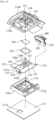
- FIG. 1 is a longitudinal cross-sectional view of a sensor module according to an embodiment of the present invention.
- a sensor module 1 includes a housing 110, a flexible substrate 120, and a temperature sensor 130.
- the housing 110 has a contact face 110c arranged and configured for installation on a surface 10.
- the surface 10 may include a windshield, a window and a mirror.
- the contact face 110c of the housing 110 has an opening 111.
- An adhesive member 117 is disposed to adhere the contact face 110c of the housing 110 to the surface 10.
- the housing 110 has an inner space.
- the housing 110 fixes and supports a base substrate part 121 of the flexible substrate 120 therein. Accordingly, the housing 110 may accommodate and protect the base substrate part 121.
- the opening 111 may be formed in a portion of the housing 110 facing the surface 10. The housing 110 withdraws a part of a curved substrate part 126 of the flexible substrate 120 via the opening 111.
- the flexible substrate 120 has the base substrate part 121 and the curved substrate part 126.
- the base substrate part 121 is fixed inside the housing 110. Accordingly, the flexible substrate 120 may be supported in the housing 110 by the base substratepart 121.
- the base substrate part 121 has a form in which a circuit is configured on a substrate formed of a material having a property of being curved.
- the curved substrate part 126 extends in a bent form of being curved from the base substrate part 121 and has an extension end 127 fixed inside the housing 110 so that a contact part 126a of the curved substrate part 126 is withdrawn via the opening 111 of the housing 110 and configured to press against the surface 10.
- the contact part 126a of the curved substrate part 126 presses against the surface 10 only by means of the curvature and the elasticity of the flexible substrate 120. Accordingly, the curved substrate part 126 is curved in a natural form and have its own tension.
- the curved substrate part 126 is integrally formed with the base substrate part 121, has a property of being curved, and is connected in circuit with the base substrate part 121.
- the flexible substrate 120 may be a flexible printed circuit board.
- the curved substrate part 126 is curved and deformed when in contact with the surface 10 while the contact part 126a is withdrawn via the opening 111 of the housing 110 so that the curved substrate part 126 remains adhered to the surface 10 due to its own tension. Accordingly, even when the surface 10 is curved, the contact part 126a of the curved substrate part 126 is deformed corresponding to the curved form of the surface 10 so that the curved substrate part 126 is adhered to the surface 10 due to its own tension.
- the curved substrate part 126 when the contact part 126a is in contact with the surface 10, the curved substrate part 126 acts like a spring due to its own tension. Accordingly, the curved substrate part 126 improves thermal contact with the surface 10 even without an additional pressing means such as a spring or a pressing rod, and due to the omission of an additional pressing means, thermal mass may be minimized.
- the temperature sensor 130 is arranged on or in the contact part 126a of the curved substrate part 126 and is configured to measure a temperature of the surface 10. That is, the temperature sensor 130 measures the temperature of the surface 10 through the curved substrate part 126 while the contact part 126a of the curved substrate part 126 is in contact with the surface 10.
- the sensor module 100 uses a single flexible substrate 120 having a relatively small thickness to measure the temperature of the surface 10. Accordingly, thermal mass may be reduced in comparison to when a hard printed circuit board (HPCB) is used.
- HPCB hard printed circuit board
- the single flexible substrate 120 is used to manufacture the base substrate part 121 and the curved substrate part 126 in an integrated form, manufacturability may be improved in comparison to when the base substrate part 121 is manufactured using a HPCB, the curved substrate part 126 is manufactured using a flexible substrate, and thebase substrate part 121 and the curved substrate part 126 are connected by soldering or the like.
- the curved substrate part 126 when the contact part 126a of the curved substrate part 126 is in contact with the surface 10 while being withdrawn via the opening 111 of the housing 110, the curved substrate part 126 may remain adhered to the surface 10 due to its own tension regardless of the curved form of the surface 10. Accordingly, since the temperature sensor 130 may promptly and accurately measure the temperature of the surface 10 through the curved substrate part 126, a prompt and accurate response is performed according to changes in fog conditions so that fog may be effectively removed from the surface 10.
- FIG. 2 is an exploded perspective view of a flexible substrate in FIG. 1 .
- the flexible substrate 120 may include a stiffener 120a laminated on at least part of the extension end 127 of the curved substrate part 126.
- the stiffener 120b may be further laminated on at least part of the base substrate part 121.
- the stiffener 120a may be laminated on fixing pieces 127a of the curved substrate part 126.
- the stiffener 120b may be laminated on an surface of the base substrate part 121 excluding a region in which a second temperature sensor 140a, a humidity sensor 140b and a control circuit module 170 are mounted and a region in which substrate terminals 123 are formed.
- the extension end 127 of the curved substrate part 126 and the base substrate part 121 are fixed inside the housing 110 while being stiffened by the stiffener 120a.
- the curved substrate part 126 may more stably maintain the curved form.
- the curved substrate part 126 may have sufficient tension even when the curved substrate part 126 has a relatively short length.
- FIG. 3 is a perspective view illustrating a state in which a curved substrate part is fixed to a housing in FIG. 1 .
- FIG. 4 is an exploded perspective view of FIG. 3 ;
- the curved substrate part 126 includes a pair of fixing pieces 127a protruding from both sides of the extension end 127.
- the housing 110 includes a pair of fitting pieces 113 and a pair of hooks 114.
- the pair of fitting pieces 113 protrude from an inner wall of the housing 110 sc that a central portion of the extension end 127 of the curved substrate part 126 is fitted therebetween.
- the pair of hooks 114 protrude from the inner wall of the housing 110 so that the fixing pieces 127a are respectively hung thereon and fixed. Accordingly, since the fixing pieces 127a of the curved substrate part 126 are fixed by being respectively hung on the hooks 114 while the central portion of the extension end 127 of the curved substrate part 126 is fitted between the fitting pieces 113, the extension end 127 of the curved substrate part 126 may be fixed inside the housing 110.
- the curved substrate part 126 may have a fixing hole formed in the extension end 127, and a fixing protrusion configured to be fitted to the fixing hole may be formed inside the housing 110 so that the extension end 127 of the curved substrate part 126 is fixed inside the housing 110.
- FIG. 5 is a perspective view of an auto defog sensor comprising the sensor module illustrated in FIG 1 .
- FIG. 6 is a perspective view illustrating a contact side of the auto defog sensor illustrated in FIG. 5 .
- FIG. 7 is a longitudinal cross-sectional view of FIG. 5 .
- FIG. 8 is a longitudinal cross-sectional view illustrating a state in which an auto defog sensor is adhered to a surface in FIG. 7 .
- FIG. 9 is an exploded perspective view of a part of the auto defog sensor illustrated in FIG. 5 .
- FIG. 10 is an exploded perspective view of FIG. 9 .
- the housing 110 may include a housing main body 110a and a housing cover 110b.
- the housing main body 110a has the opening 111.
- the housing main body 110a has an open side which faces a side that comprises the opening 111.
- the housing cover 110b is configured to cover the open side of the housing main body 110a.
- the fitting pieces 113 and the hooks 114 are formed in an inner wall of the housing cover 110b.
- the housing 110 has the form in which the housing main body 110a and the housing cover 110b are assembled to or separated from each other, thereby facilitating assembly of the flexible substrate 120, a connector 180, or the like accommodated in the housing 110.
- the housing cover 110b may have a form in which the circumference of the housing cover 110b surrounds the circumference of the housing main body 110a.
- the housing main body 110a may have coupling protrusions 115a formed in an outer wall, and the housing cover 110b may have coupling grooves 115b formed in a circumferential inner wall so that the coupling protrusions 115a are respectively fitted thereto.
- the housing cover 110b may be easily adhered to or detached from the housing main body 110a by coupling or separation between the coupling protrusions 115a and the coupling grooves 115b.
- the base substrate part 121 may be supported on the open side of the housing main body 110a.
- the housing main body 110a may include a hollow support part 116.
- the hollow support part 116 protrudes in a hollow form from an inner surface of the contact face 110c of the housing main body 110a, has an open side at the protruded end and is configured to support a central portion of the base substrate part 121.
- the hollow support part 116 may be formed in the shape of a quadrilateral container having a hollow.
- the base substrate part 121 is supported by the open side ofthe housing main body 110a and the open side of the hollow support part 116.
- the base substrate part 121 and the curved substrate part 126 may be insulated from each other due to an enclosure of the housing main body 110a and the hollow of the hollow support part 116. Accordingly, the base substrate part 121 and the curved substrate part 126 are less affected by ambient heat such that the temperature sensor 130 is able to more accurately measure the temperature of the surface 10.
- the housing main body 110a may be adhered to the surface 10 by the adhesive member 117.
- the adhesive member 117 is disposed to adhere the contact face 110c of the housing main body 110a to the surface 10.
- the adhesive member 117 has a size corresponding to that of the contact face 110c of the housing main body 110a, and the curved substrate part 126 may pass through a hole 117a of the adhesive member 117 formed in a portion corresponding to the opening 111 of the housing main body 110a.
- Both surfaces of the adhesive member 117 have an adhesive property.
- the contact face 110c of the housing main body 110a is adhered to one adhesive surface of the adhesive member 117, and the surface 10 is adhered to the other adhesive surface of the adhesive member 117.
- the adhesive member 117 may be formed of a soft material so that the adhesive member 117 has a sufficient adhesive force even when the housing main body 110a is adhered to a curved or bent surface 10.
- the adhesive member 117 may be formed as a double-sided tape.
- the temperature sensor 130 may be mounted in an opposite surface side of the contacted surface of the contact part 126a and be connected to a circuit of the curved substrate part 126. That is, the temperature sensor 130 is disposed opposite the surface 10 while the contact part 126a of the curved substrate part 126 is disposed therebetween. Accordingly, the temperature sensor 130 may receive heat of the surface 10 from the curved substrate part 126, which is in contact with the surface 10 and measure the temperature of the surface 10. To reduce thermal mass, it may be advantageous for the size of the temperature sensor 130 to be reduced.
- the temperature sensor 130 may comprise or be a thermistor.
- the base substrate part 121 may include extending pieces 122.
- the extending pieces 122 respectively extend from both sides of the base substrate part 121 while the curved substrate part 126 is disposed therebetween, and the extending pieces 122 are fixed inside the housing 110. Accordingly, an area in which the base substrate part 121 is fixed inside the housing 110, i.e., fixed to the open side of the housing main body 110a, may be increased, and the base substrate part 121 may be more stably supported.
- Each of the extending pieces 122 may extend while being spaced apart from the curved substrate part 126. Accordingly, the curved substrate part 126 may be smoothly deformed without interfering with the base substrate part 121. A connection portion at which the extending pieces 122 and the curved substrate part 126 are connected is processed to be round so that tearing of the connection portion is prevented.
- the curved substrate part 126 may extend with a width narrower than the width of the base substrate part 121.
- the tension of the curved substrate part 126 may decrease as the width of the curved substrate part 126 becomes narrower. Conversely, the tension of the curved substrate part 126 may increase as the width of the curved substrate part 126 is wider.
- the width of the curved substrate part 126 may be set to be in an optimal range in consideration of the tension of the curved substrate part 126. That is, the width of the curved substrate part 126 may be set to be in a range that satisfies a condition that the tension of the curved substrate part 126 be maintained to a set value or higher.
- Portions of the curved substrate part 126 may be formed to have a constant width, excluding a portion connected to the base substrate part 121 and a portion fixed to the housing 110.
- the curved substrate part 126 may extend by being bent in the form of being inflected from the portion connected to the base substrate part 121 toward the contact part 126a.
- the curved substrate part 126 is guided to be bent to the surface 10 from the base substrate part 121 by a guiding block 112 which is arranged inside the housing 110.
- a protruded surface of the guiding block 112 is inclined in a direction in which the curved substrate part 126 extends.
- the contact part 126a of the curved substrate part 126 is withdrawn in a convexly bent form from the opening 111 of the housing 110. Accordingly, the curved substrate part 126 is curved in a natural form and have its own tension.
- the sensor module 1 further may comprise the connector 180.
- the connector 180 may be connected to the substrate terminals 123 of the base substrate part 121 by connector terminals 182 while the connector 180 is aligned by aligning protrusions 181 fitted to aligning holes 124 of the base substrate part 121.
- the aligning holes 124 may be formed corresponding to the open side of the housing main body 110a, and the aligning protrusions 181 may be fitted thereto.
- a body portion of the connector 180 may be supported by being fitted to a rear end opening of the housing main body 110a so that the base substrate part 121 is adhered to the open side of the housing main body 110a.
- an auto defog sensor 100 comprises the sensor module 1, further may comprise the second temperature sensor 140a and the humidity sensor 140b.
- the second temperature sensor 140a may be disposed on the base substrate part 121.
- the second temperature sensor 140a may be mounted on the base substrate part 121 which is arranged and configured to measure an ambient temperature.
- the second temperature sensor 140a and the humidity sensor 140b may be used along with the temperature sensor 130 to accurately calculate a dew point value.
- the humidity sensor 140b may be arranged and configured to measure an ambient humidity.
- the humidity sensor 140b may be mounted on the base substrate part 121.
- the humidity sensor 140b may be separated with the second temperature sensor 140a and be mounted on the base substrate part 121.
- the humidity sensor 140b may integrated with the second temperature sensor 140a or the temperature sensor 130.
- the temperature sensor 130 is integrated in a semiconductor chip and wherein the humidity sensor 140b is integrated in the same semiconductor chip.
- the second temperature sensor 140a is integrated in a semiconductor chip and wherein the humidity sensor 140b is integrated in the same semiconductor chip.
- the hollow accommodating part 119 protrudes in a hollow form from a surrounding inner wall of the air inlet 118 and accommodates the second temperature sensor 140a.
- the hollow accommodating part 119 may be formed in the shape of a quadrilateral container having a hollow.
- the hollow accommodating part 119 may be formed to protrude from an inner wall of the housing cover 110b. While the housing cover 110b is mounted on the housing main body 110a, the protruded end of the hollow accommodating part 119 presses a faced surface of the base substrate part 121 via a sealing tape 150, thereby fixing the base substrate part 121 to the housing main body 110a.
- the sealing tape 150 seals between the hollow accommodating part 119 and the base substrate part 121.
- the sealing tape 150 prevents introduction of foreign substances through a gap between the hollow accommodating part 119 and the base substratepart 121.
- the sealing tape 150 may be formed in the shape of a quadrilateral ring to correspond to the form of the protruded end of the hollow accommodating part 119.
- the sealing tape 150 may be adhered to at least one of the base substrate part 121 and the hollow accommodating part 119.
- the second temperature sensor 140a is mounted in the base substrate part 121 disposed inside the housing 110 and is accommodated in the hollow accommodating part 119 while the temperature sensor 130 is mounted in the contact part 126a of the curved substrate part 126 withdrawn via the opening 111 of the housing 110.
- the second temperature sensor 140a and the temperature sensor 130 may be spatially divided. Accordingly, since measurement of temperature of the surface 10 and measurement of temperature of the indoor e.g. of the vehicle may be sufficiently separated, a prompt and accurate response may be performed according to changes in fog conditions.
- a filter 160 may be installed in the air inlet 118.
- the filter 160 removes foreign substances from air introduced via the air inlet 118.
- the filter 160 may be disposed inside the air inlet 118.
- the filter 160 may be formed as a membrane filter.
- the auto defog sensor 100 may comprise the control circuit module 170.
- the control circuit module 170 may be disposed on the base substrate part 121.
- the control circuit module 170 may be mounted on the base substrate part 121 and accommodated in the hollow accommodating part 119.
- the control circuit module 170 compares a dew point, which is obtained by computing a value measured by the second temperature sensor 140a and the humidity sensor 140b, with the temperature of the surface 10 measured by the temperature sensor 130 and selectively outputs a fog detection signal.
- the control circuit module 170 calculates a dew point on the basis of a generally-known formula which calculates a dew point from a relative humidity value and an indoor temperature value. Next, the control circuit module 170 compares the calculated dew point with the temperature of the surface, and when the dew point has a value higher than or equal to the temperature of the surface, the control circuit module 170 predicts that fog may be formed on the surface 10 and outputs a fog detection signal.
- the fog detection signal output as above is provided to an air conditioning system of the vehicle, thereby allowing air conditioning to be performed so that fog is not formed on the surface 10.
- the connector 180 may be in charge of power supply and data input/output of the control circuit module 170. That is, the connector 180 may be connected via a wire harness to a control box configured to control electric components of the vehicle. Accordingly, when a fog detection signal is input from the control circuit module 170 to the control box via the connector 180, the control box may perform control to remove fog or prevent fogging on the surface 10 by performing dehumidification using the air conditioning system.
- thermal mass can be reduced in comparison to when a UPCB is used to measure a temperature of a surface.
Landscapes
- Physics & Mathematics (AREA)
- General Physics & Mathematics (AREA)
- Mechanical Engineering (AREA)
- Chemical & Material Sciences (AREA)
- Engineering & Computer Science (AREA)
- Thermal Sciences (AREA)
- Analytical Chemistry (AREA)
- Life Sciences & Earth Sciences (AREA)
- Health & Medical Sciences (AREA)
- Biochemistry (AREA)
- General Health & Medical Sciences (AREA)
- Immunology (AREA)
- Pathology (AREA)
- Electrochemistry (AREA)
- Chemical Kinetics & Catalysis (AREA)
- Nonlinear Science (AREA)
- Measuring Temperature Or Quantity Of Heat (AREA)
- Testing Or Calibration Of Command Recording Devices (AREA)
- Air-Conditioning For Vehicles (AREA)
Description
- The present invention relates to a sensor module capable of accurately and rapidly measuring a temperature of a surface and to an auto defog sensor (ADS) comprising such a sensor module. The ADS is capable of effectively predicting and/or detecting fogging of a surface.
- Generally, ADSs for predicting and/or detecting fogging on a surface are known. Relevant surfaces include windshields, windows and mirrors. An ADS may be employed to predict and/or detect fogging on a windshield of a vehicle or on amirror
e.g. in the bathroom. Such ADSs predict and/or detect fogging, which begins to form on the surface, and may in association with a heating and/or an air conditioning system automatically prevent or remove the fogging. In a vehicle an ADS may be employed on the windshield of the vehicle, thereby allowing a driver to drive safely. - Such ADSs have already been disclosed domestically and internationally. An example thereof includes an ADS disclosed in
U.S. Patent No. 6,422,062 . This ADS includes a glass temperature sensor, a relative humidity sensor, and an ambient air temperature sensor, and to calculate a relatively accurate dew point value, the relative humidity sensor and the ambient air temperature sensor are located to be adjacent to each other so as to measure a humidity level and a temperature at the same point. - However, according to the related art, a surface temperature is generally measured by a temperature sensor being adhered to the surface by an adhesive member. Thus, there is a concern that a gap may be generated between the temperature measurement unit and the adhesive member due to various reasons such as the glass surface being curved or foreign substances being introduced between the temperature measurement unit and the adhesive member. Then, an error may occur in the measured surface temperature, and fog may not be effectively predicted and/or detected.
- Another example includes an ADS disclosed in
U.S. Patent No. 7,770,433 . Here, a surface temperature is measured by a temperature sensor, which is pressed against the windshield by a spring. This spring enables a good thermal contact between the tem- perature sensor and the windshield but it has a high thermal mass and it provides a strong thermal contact to the sensor. Thus, the temperature sensor may react slower to changes of the temperature of the windshield and the measured temperature may less accurately correspond to the temperature of the windshield. Additionally, the spring and the assembly of the spring may be complex and costly. - A further example of an ADS is disclosed in
KR 10 2017 0018546 A -
JP 2012 233 862 A - The present invention is directed to providing a sensor module capable of accurately and rapidly measuring a temperature of a surface.
- Furthermore, it is an object of the present invention to provide an auto defog sensor with improved manufacturability that is capable of accurately and rapidly predicting and/or detecting fogging of a surface.
- To achieve the above object, a sensor module according to
claim 1 is provided. The housing has a contact face arranged and configured for installation on a surface, wherein the contact face of the housing has an opening. A flexible substrate has a base substrate part fixed inside the housing and a curved substrate part which extends in a bent form from the base substrate part and has an extension end fixed inside the housing so that a contact part of the curved substrate part is withdrawn in a convexly bent form from the opening of the housing and configured to press against the surface. The temperature sensor is arranged on or in the contact part of the curved substrate part and configured to measure a temperature of the surface. - According to the invention, the contact part of the curved substrate part presses against the surface only by means of the curvature and the elasticity of the flexible substrate. An advantage of the invention is that additional parts may be spared and that thereby the thermal mass is reduced and thereby the response time to temperature changes is shortened.
- The curved substrate part is guided to be bent from the base substrate part by a guiding block which is arranged inside the housing. An advantage of this is that the thermal contact of the temperature sensor to the surface is increased and remains reliable over time. Therefore, accuracy and reliability may be increased.
- In a preferred embodiment, the flexible substrate may include a stiffener laminated at the extension end of the curved substrate part and/or laminated at the base substrate part. According to the invention, the curved substrate part includes a pair of fixing pieces protruding from both sides of the extension end.
- According to the invention, the housing includes a pair of fitting pieces protruding from an inner wall of the housing so that a central portion of the extension end of the curved substrate part is fitted therebetween, and a pair of hooks protruding from the inner wall of the housing so that the fixing pieces are respectively hung thereon and fixed. The temperature sensor may be formed as athermistor. Advantages of a thermistor may be that it may be cheap and that it may have a small thermal mass and that it may therefore have a fast response time.
- An auto defog sensor comprises the sensor module and further comprises a humidity sensor arranged and configured to measure an ambient humidity.
- In an embodiment, the temperature sensor is integrated in a semiconductor chip and the humidity sensor is integrated in the same semiconductor chip. An advantage of this embodiment is that temperature and humidity are directly measured at the surface ("direct ADS") and that therefore only one single temperature sensor is required. By using the same, single, small semiconductor chip for the temperature and the humidity, the size and therefore the thermal mass may be small and therefore the response time may be fast.
- In another embodiment, the auto defog sensor further comprises a second temperature sensor mounted on the base substrate part which is arranged and configured to measure an ambient temperature and wherein the humidity sensor is mounted on the base substrate part ("indirect ADS"). For this embodiment, preferably, the second temperature sensor is integrated in a semiconductor chip and the humidity sensor is integrated in the same semiconductor chip.
- The present invention is able to provide an auto defog sensor with improved manufacturability that is capable of accurately and rapidly predicting and/or detecting fogging of a surface.
- The present invention is able to reduce the thermal mass than using a hard printed circuit board (Hard Printed Circuit Board) to measure the surface temperature.
- According to the present invention, by manufacturing the base substrate part as a hard printed circuit board and the curved substrate part as a flexible substrate, the manufacturability can be improved compared to connecting the base substrate part and the curved substrate part by soldering or the like.
- In addition, according to the present invention, it is possible to effectively remove the fogging of a surface by making a quick and accurate response according to the change of the fogging condition.
-
-
FIG. 1 is a longitudinal cross-sectional view of a sensor module according to an embodiment of the present invention; -
FIG. 2 is an exploded perspective view of a flexible substrate inFIG. 1 ; -
FIG. 3 is a perspective view illustrating a state in which a curved substrate part is fixed to a housing inFIG. 1 , -
FIG. 4 is an exploded perspective view ofFIG. 3 ; -
FIG. 5 is a perspective view of an auto defog sensor comprising the sensor module illustrated inFIG 1 ; -
FIG. 6 is a perspective view illustrating a contact side of the auto defog sensor illustrated inFIG. 5 ; -
FIG. 7 is a longitudinal cross-sectional view ofFIG. 5 ; -
FIG. 8 is a longitudinal cross-sectional view illustrating a state in which an auto defog sensor is adhered to a surface inFIG. 7 ; -
FIG. 9 is an exploded perspective view of a part of the auto defog sensor illustrated inFIG. 5 ; and -
FIG. 10 is an exploded perspective view ofFIG. 9 ; - The present invention will be described in detail below with reference to the accompanying drawings. Here, like configurations will be denoted by like reference numerals, repetitive description will be avoided, and detailed description of known functions and configurations that may unnecessarily blur the gist of the present invention will be omitted. Embodiments of the present invention are provided to more fully describe the present invention to those of ordinary skill in the art. Therefore, the shape, sizes, or the like of the elements in the drawings may be exaggerated for clarity of description.
-
FIG. 1 is a longitudinal cross-sectional view of a sensor module according to an embodiment of the present invention. - Referring to
FIG. 1 , asensor module 1 includes ahousing 110, aflexible substrate 120, and atemperature sensor 130. - The
housing 110 has acontact face 110c arranged and configured for installation on asurface 10. Thesurface 10 may include a windshield, a window and a mirror. Thecontact face 110c of thehousing 110 has anopening 111. Anadhesive member 117 is disposed to adhere thecontact face 110c of thehousing 110 to thesurface 10. - The
housing 110 has an inner space. Thehousing 110 fixes and supports abase substrate part 121 of theflexible substrate 120 therein. Accordingly, thehousing 110 may accommodate and protect thebase substrate part 121. Theopening 111 may be formed in a portion of thehousing 110 facing thesurface 10. Thehousing 110 withdraws a part of acurved substrate part 126 of theflexible substrate 120 via theopening 111. - The
flexible substrate 120 has thebase substrate part 121 and thecurved substrate part 126. Thebase substrate part 121 is fixed inside thehousing 110. Accordingly, theflexible substrate 120 may be supported in thehousing 110 by thebase substratepart 121. Thebase substrate part 121 has a form in which a circuit is configured on a substrate formed of a material having a property of being curved. - The
curved substrate part 126 extends in a bent form of being curved from thebase substrate part 121 and has anextension end 127 fixed inside thehousing 110 so that acontact part 126a of thecurved substrate part 126 is withdrawn via theopening 111 of thehousing 110 and configured to press against thesurface 10. Thecontact part 126a of thecurved substrate part 126 presses against thesurface 10 only by means of the curvature and the elasticity of theflexible substrate 120. Accordingly, thecurved substrate part 126 is curved in a natural form and have its own tension. - The
curved substrate part 126 is integrally formed with thebase substrate part 121, has a property of being curved, and is connected in circuit with thebase substrate part 121. Theflexible substrate 120 may be a flexible printed circuit board. - The
curved substrate part 126 is curved and deformed when in contact with thesurface 10 while thecontact part 126a is withdrawn via theopening 111 of thehousing 110 so that thecurved substrate part 126 remains adhered to thesurface 10 due to its own tension. Accordingly, even when thesurface 10 is curved, thecontact part 126a of thecurved substrate part 126 is deformed corresponding to the curved form of thesurface 10 so that thecurved substrate part 126 is adhered to thesurface 10 due to its own tension. - That is, when the
contact part 126a is in contact with thesurface 10, thecurved substrate part 126 acts like a spring due to its own tension. Accordingly, thecurved substrate part 126 improves thermal contact with thesurface 10 even without an additional pressing means such as a spring or a pressing rod, and due to the omission of an additional pressing means, thermal mass may be minimized. - The
temperature sensor 130 is arranged on or in thecontact part 126a of thecurved substrate part 126 and is configured to measure a temperature of thesurface 10. That is, thetemperature sensor 130 measures the temperature of thesurface 10 through thecurved substrate part 126 while thecontact part 126a of thecurved substrate part 126 is in contact with thesurface 10. - As described above, the
sensor module 100 according to the embodiment of the present invention uses a singleflexible substrate 120 having a relatively small thickness to measure the temperature of thesurface 10. Accordingly, thermal mass may be reduced in comparison to when a hard printed circuit board (HPCB) is used. - In addition, in the embodiment of the present invention, since the single
flexible substrate 120 is used to manufacture thebase substrate part 121 and thecurved substrate part 126 in an integrated form, manufacturability may be improved in comparison to when thebase substrate part 121 is manufactured using a HPCB, thecurved substrate part 126 is manufactured using a flexible substrate, andthebase substrate part 121 and thecurved substrate part 126 are connected by soldering or the like. - According to the embodiment of the present invention, when the
contact part 126a of thecurved substrate part 126 is in contact with thesurface 10 while being withdrawn via theopening 111 of thehousing 110, thecurved substrate part 126 may remain adhered to thesurface 10 due to its own tension regardless of the curved form of thesurface 10. Accordingly, since thetemperature sensor 130 may promptly and accurately measure the temperature of thesurface 10 through thecurved substrate part 126, a prompt and accurate response is performed according to changes in fog conditions so that fog may be effectively removed from thesurface 10. -
FIG. 2 is an exploded perspective view of a flexible substrate inFIG. 1 . - Referring to
FIG. 2 , theflexible substrate 120 may include astiffener 120a laminated on at least part of theextension end 127 of thecurved substrate part 126. Thestiffener 120b may be further laminated on at least part of thebase substrate part 121. Thestiffener 120a may be laminated on fixingpieces 127a of thecurved substrate part 126. In addition, thestiffener 120b may be laminated on an surface of thebase substrate part 121 excluding a region in which asecond temperature sensor 140a, ahumidity sensor 140b and acontrol circuit module 170 are mounted and a region in whichsubstrate terminals 123 are formed. - As described above, the
extension end 127 of thecurved substrate part 126 and thebase substrate part 121 are fixed inside thehousing 110 while being stiffened by thestiffener 120a. Thus, thecurved substrate part 126 may more stably maintain the curved form. In addition, thecurved substrate part 126 may have sufficient tension even when thecurved substrate part 126 has a relatively short length. -
FIG. 3 is a perspective view illustrating a state in which a curved substrate part is fixed to a housing inFIG. 1 .FIG. 4 is an exploded perspective view ofFIG. 3 ; - Referring to
FIGS. 3 and 4 , thecurved substrate part 126 includes a pair of fixingpieces 127a protruding from both sides of theextension end 127. In addition, thehousing 110 includes a pair offitting pieces 113 and a pair ofhooks 114. - The pair of
fitting pieces 113 protrude from an inner wall of thehousing 110 sc that a central portion of theextension end 127 of thecurved substrate part 126 is fitted therebetween. The pair ofhooks 114 protrude from the inner wall of thehousing 110 so that the fixingpieces 127a are respectively hung thereon and fixed. Accordingly, since the fixingpieces 127a of thecurved substrate part 126 are fixed by being respectively hung on thehooks 114 while the central portion of theextension end 127 of thecurved substrate part 126 is fitted between thefitting pieces 113, theextension end 127 of thecurved substrate part 126 may be fixed inside thehousing 110. - As another example, although not illustrated and not forming part of the invention, the
curved substrate part 126 may have a fixing hole formed in theextension end 127, and a fixing protrusion configured to be fitted to the fixing hole may be formed inside thehousing 110 so that theextension end 127 of thecurved substrate part 126 is fixed inside thehousing 110. -
FIG. 5 is a perspective view of an auto defog sensor comprising the sensor module illustrated inFIG 1 .FIG. 6 is a perspective view illustrating a contact side of the auto defog sensor illustrated inFIG. 5 .FIG. 7 is a longitudinal cross-sectional view ofFIG. 5 .FIG. 8 is a longitudinal cross-sectional view illustrating a state in which an auto defog sensor is adhered to a surface inFIG. 7 .FIG. 9 is an exploded perspective view of a part of the auto defog sensor illustrated inFIG. 5 .FIG. 10 is an exploded perspective view ofFIG. 9 . - Referring to
FIGS. 5 to 10 , thehousing 110 may include a housingmain body 110a and ahousing cover 110b. The housingmain body 110a has theopening 111. The housingmain body 110a has an open side which faces a side that comprises theopening 111. - The
housing cover 110b is configured to cover the open side of the housingmain body 110a. Thefitting pieces 113 and thehooks 114 are formed in an inner wall of thehousing cover 110b. - The
housing 110 has the form in which the housingmain body 110a and thehousing cover 110b are assembled to or separated from each other, thereby facilitating assembly of theflexible substrate 120, aconnector 180, or the like accommodated in thehousing 110. - The
housing cover 110b may have a form in which the circumference of thehousing cover 110b surrounds the circumference of the housingmain body 110a. The housingmain body 110a may havecoupling protrusions 115a formed in an outer wall, and thehousing cover 110b may havecoupling grooves 115b formed in a circumferential inner wall so that thecoupling protrusions 115a are respectively fitted thereto. Thehousing cover 110b may be easily adhered to or detached from the housingmain body 110a by coupling or separation between thecoupling protrusions 115a and thecoupling grooves 115b. - The
base substrate part 121 may be supported on the open side of the housingmain body 110a. The housingmain body 110a may include ahollow support part 116. Thehollow support part 116 protrudes in a hollow form from an inner surface of thecontact face 110c of the housingmain body 110a, has an open side at the protruded end and is configured to support a central portion of thebase substrate part 121. Thehollow support part 116 may be formed in the shape of a quadrilateral container having a hollow. - As described above, the
base substrate part 121 is supported by the open side ofthe housingmain body 110a and the open side of thehollow support part 116. Thus, thebase substrate part 121 and thecurved substrate part 126 may be insulated from each other due to an enclosure of the housingmain body 110a and the hollow of thehollow support part 116. Accordingly, thebase substrate part 121 and thecurved substrate part 126 are less affected by ambient heat such that thetemperature sensor 130 is able to more accurately measure the temperature of thesurface 10. - The housing
main body 110a may be adhered to thesurface 10 by theadhesive member 117. Theadhesive member 117 is disposed to adhere thecontact face 110c of the housingmain body 110a to thesurface 10. Theadhesive member 117 has a size corresponding to that of thecontact face 110c of the housingmain body 110a, and thecurved substrate part 126 may pass through ahole 117a of theadhesive member 117 formed in a portion corresponding to theopening 111 of the housingmain body 110a. - Both surfaces of the
adhesive member 117 have an adhesive property. Thecontact face 110c of the housingmain body 110a is adhered to one adhesive surface of theadhesive member 117, and thesurface 10 is adhered to the other adhesive surface of theadhesive member 117. Theadhesive member 117 may be formed of a soft material so that theadhesive member 117 has a sufficient adhesive force even when the housingmain body 110a is adhered to a curved orbent surface 10. For example, theadhesive member 117 may be formed as a double-sided tape. - Meanwhile, the
temperature sensor 130 may be mounted in an opposite surface side of the contacted surface of thecontact part 126a and be connected to a circuit of thecurved substrate part 126. That is, thetemperature sensor 130 is disposed opposite thesurface 10 while thecontact part 126a of thecurved substrate part 126 is disposed therebetween. Accordingly, thetemperature sensor 130 may receive heat of thesurface 10 from thecurved substrate part 126, which is in contact with thesurface 10 and measure the temperature of thesurface 10. To reduce thermal mass, it may be advantageous for the size of thetemperature sensor 130 to be reduced. For example, thetemperature sensor 130 may comprise or be a thermistor. - Meanwhile, the
base substrate part 121 may include extendingpieces 122. The extendingpieces 122 respectively extend from both sides of thebase substrate part 121 while thecurved substrate part 126 is disposed therebetween, and the extendingpieces 122 are fixed inside thehousing 110. Accordingly, an area in which thebase substrate part 121 is fixed inside thehousing 110, i.e., fixed to the open side of the housingmain body 110a, may be increased, and thebase substrate part 121 may be more stably supported. - Each of the extending
pieces 122 may extend while being spaced apart from thecurved substrate part 126. Accordingly, thecurved substrate part 126 may be smoothly deformed without interfering with thebase substrate part 121. A connection portion at which the extendingpieces 122 and thecurved substrate part 126 are connected is processed to be round so that tearing of the connection portion is prevented. - Meanwhile, the
curved substrate part 126 may extend with a width narrower than the width of thebase substrate part 121. The tension of thecurved substrate part 126 may decrease as the width of thecurved substrate part 126 becomes narrower. Conversely, the tension of thecurved substrate part 126 may increase as the width of thecurved substrate part 126 is wider. Accordingly, the width of thecurved substrate part 126 may be set to be in an optimal range in consideration of the tension of thecurved substrate part 126. That is, the width of thecurved substrate part 126 may be set to be in a range that satisfies a condition that the tension of thecurved substrate part 126 be maintained to a set value or higher. - Portions of the
curved substrate part 126 may be formed to have a constant width, excluding a portion connected to thebase substrate part 121 and a portion fixed to thehousing 110. Thecurved substrate part 126 may extend by being bent in the form of being inflected from the portion connected to thebase substrate part 121 toward thecontact part 126a. - The
curved substrate part 126 is guided to be bent to thesurface 10 from thebase substrate part 121 by a guidingblock 112 which is arranged inside thehousing 110. A protruded surface of the guidingblock 112 is inclined in a direction in which thecurved substrate part 126 extends. In addition, thecontact part 126a of thecurved substrate part 126 is withdrawn in a convexly bent form from theopening 111 of thehousing 110. Accordingly, thecurved substrate part 126 is curved in a natural form and have its own tension. - Meanwhile, the
sensor module 1 further may comprise theconnector 180. Theconnector 180 may be connected to thesubstrate terminals 123 of thebase substrate part 121 byconnector terminals 182 while theconnector 180 is aligned by aligningprotrusions 181 fitted to aligningholes 124 of thebase substrate part 121. Here, the aligningholes 124 may be formed corresponding to the open side of the housingmain body 110a, and the aligningprotrusions 181 may be fitted thereto. A body portion of theconnector 180 may be supported by being fitted to a rear end opening of the housingmain body 110a so that thebase substrate part 121 is adhered to the open side of the housingmain body 110a. - Meanwhile, an
auto defog sensor 100 comprises thesensor module 1, further may comprise thesecond temperature sensor 140a and thehumidity sensor 140b. - The
second temperature sensor 140a may be disposed on thebase substrate part 121. Thesecond temperature sensor 140a may be mounted on thebase substrate part 121 which is arranged and configured to measure an ambient temperature. Thesecond temperature sensor 140a and thehumidity sensor 140b may be used along with thetemperature sensor 130 to accurately calculate a dew point value. - The
humidity sensor 140b may be arranged and configured to measure an ambient humidity. Thehumidity sensor 140b may be mounted on thebase substrate part 121. Thehumidity sensor 140b may be separated with thesecond temperature sensor 140a and be mounted on thebase substrate part 121. - Another example, the
humidity sensor 140b may integrated with thesecond temperature sensor 140a or thetemperature sensor 130. Thetemperature sensor 130 is integrated in a semiconductor chip and wherein thehumidity sensor 140b is integrated in the same semiconductor chip. Thesecond temperature sensor 140a is integrated in a semiconductor chip and wherein thehumidity sensor 140b is integrated in the same semiconductor chip. - The
auto defog sensor 100 may comprise anair inlet 118 and a hollowaccommodating part 119. Theair inlet 118 is formed in a side which faces thecontact face 110c of thehousing 110 corresponding to thesecond temperature sensor 140a on the basis of the state that thehousing 110 is placed above thesurface 10. Theair inlet 118 allows air flowing along thesurface 10 to be provided to thesecond temperature sensor 140a. Theair inlet 118 may be divided into a plurality of compartments by partitions. Theair inlet 118 may be formed in thehousing cover 110b. - The hollow
accommodating part 119 protrudes in a hollow form from a surrounding inner wall of theair inlet 118 and accommodates thesecond temperature sensor 140a. The hollowaccommodating part 119 may be formed in the shape of a quadrilateral container having a hollow. The hollowaccommodating part 119 may be formed to protrude from an inner wall of thehousing cover 110b. While thehousing cover 110b is mounted on the housingmain body 110a, the protruded end of the hollowaccommodating part 119 presses a faced surface of thebase substrate part 121 via a sealingtape 150, thereby fixing thebase substrate part 121 to the housingmain body 110a. - The sealing
tape 150 seals between the hollowaccommodating part 119 and thebase substrate part 121. The sealingtape 150 prevents introduction of foreign substances through a gap between the hollowaccommodating part 119 and thebase substratepart 121. The sealingtape 150 may be formed in the shape of a quadrilateral ring to correspond to the form of the protruded end of the hollowaccommodating part 119. The sealingtape 150 may be adhered to at least one of thebase substrate part 121 and the hollowaccommodating part 119. - As described above, the
second temperature sensor 140a is mounted in thebase substrate part 121 disposed inside thehousing 110 and is accommodated in the hollowaccommodating part 119 while thetemperature sensor 130 is mounted in thecontact part 126a of thecurved substrate part 126 withdrawn via theopening 111 of thehousing 110. Thus, in addition to having different mounting heights, thesecond temperature sensor 140a and thetemperature sensor 130 may be spatially divided. Accordingly, since measurement of temperature of thesurface 10 and measurement of temperature of the indoor e.g. of the vehicle may be sufficiently separated, a prompt and accurate response may be performed according to changes in fog conditions. - A
filter 160 may be installed in theair inlet 118. Thefilter 160 removes foreign substances from air introduced via theair inlet 118. Thefilter 160 may be disposed inside theair inlet 118. Thefilter 160 may be formed as a membrane filter. - The
auto defog sensor 100 may comprise thecontrol circuit module 170. Thecontrol circuit module 170 may be disposed on thebase substrate part 121. Thecontrol circuit module 170 may be mounted on thebase substrate part 121 and accommodated in the hollowaccommodating part 119. Thecontrol circuit module 170 compares a dew point, which is obtained by computing a value measured by thesecond temperature sensor 140a and thehumidity sensor 140b, with the temperature of thesurface 10 measured by thetemperature sensor 130 and selectively outputs a fog detection signal. - That is, the
control circuit module 170 calculates a dew point on the basis of a generally-known formula which calculates a dew point from a relative humidity value and an indoor temperature value. Next, thecontrol circuit module 170 compares the calculated dew point with the temperature of the surface, and when the dew point has a value higher than or equal to the temperature of the surface, thecontrol circuit module 170 predicts that fog may be formed on thesurface 10 and outputs a fog detection signal. The fog detection signal output as above is provided to an air conditioning system of the vehicle, thereby allowing air conditioning to be performed so that fog is not formed on thesurface 10. - The
connector 180 may be in charge of power supply and data input/output of thecontrol circuit module 170. That is, theconnector 180 may be connected via a wire harness to a control box configured to control electric components of the vehicle. Accordingly, when a fog detection signal is input from thecontrol circuit module 170 to the control box via theconnector 180, the control box may perform control to remove fog or prevent fogging on thesurface 10 by performing dehumidification using the air conditioning system. - The present invention has been described above with reference to the embodiments illustrated in the drawings, but the description is merely illustrative. Therefore, the actual technical scope of the present invention should be defined on the basis of the claims below.
- According to the present invention, thermal mass can be reduced in comparison to when a UPCB is used to measure a temperature of a surface.
Claims (13)
- A sensor module (1) for installation on a surface (10) comprising:a housing (110) which has a contact face (110c) arranged and configured for installation on the surface (10), wherein the contact face (110c) of the housing (110) has an opening (111);a flexible substrate (120) having a base substrate part (121) fixed inside the housing (110) and a curved substrate part (126) which extends in a bent form from the base substrate part (121) and has an extension end (127) fixed inside the housing (110) so that a contact part (126a) of the curved substrate part (126) is withdrawn in a convexly bent form from the opening (111) of the housing (110) and configured to press against the surface (10); anda temperature sensor (130) arranged on or in the contact part (126a) of the curved substrate part (126) and configured to measure a temperature of the surface (10),wherein the curved substrate part (126) is guided to be bent from the base substrate part (121) by a guiding block (112) which is arranged inside the housing (110),characterized in that the curved substrate part (126) includes a pair of fixing pieces (127a) protruding from both sides of the extension end (127); andthe housing (110) includes a pair of fitting pieces (113) protruding from an inner wall of the housing (110) so that a central portion of the extension end (127) of the curved substrate part (126) is fitted therebetween, and a pair of hooks (114) protruding from the inner wall of the housing (110) so that the fixing pieces (127a) are respectively hung thereon and fixed;and in that a protruded surface of the guiding block (112) is inclined in a direction in which the curved substrate part (126) extends, such that the curved substrate part (126) is curved in a natural form and has its own tension.
- The sensor module of claim 1, wherein the contact part (126a) of the curved substrate part (126) presses against the surface (10) only by means of the curvature and the elasticity of the flexible substrate (120).
- The sensor module according to claim 1, wherein the flexible substrate (120) comprises a stiffener (120a) laminated on at least part of the extension end (127) of the curved substrate part (126).
- The sensor module according to claim 1, wherein the flexible substrate (120) comprises a stiffener (120b) laminated on at least part of the base substrate part (121).
- The sensor module according to claim 1, wherein the temperature sensor (130) comprises a thermistor.
- The sensor module according to claim 1, wherein the housing (110) further includes:a housing main body (110a) which has the opening (111) and an open side which faces a side that comprises the opening (111); anda housing cover (110b) which is configured to cover the open side of the housing main body (110a).
- The sensor module according to claim 6, wherein the base substrate part (121) is supported on the open side of the housing main body (110a).
- The sensor module according to the claim 6, wherein the housing main body (110a) includes a hollow support part (116) which protrudes in a hollow form from an inner surface of the contact face (110c), has an open side at the protruded end and is configured to support a central portion of the base substrate part (121).
- The sensor module according to claim 1, further comprising a connector (180) connected to substrate terminals (123) of the base substrate part (121) by connector terminals (182) of the connector while the connector (180) is aligned by aligning protrusions (181) fitted to aligning holes (124) of the base substrate part (121).
- The sensor module according to claim 1, wherein the base substrate part (121) includes extending pieces (122) which respectively extend from both sides of the base substrate part (121) while the curved substrate part (126) is disposed therebetween and which are fixed inside the housing (110).
- The sensor module according to claim 10, wherein each of the extending pieces (122) extend while being spaced apart from the curved substrate part (126).
- An auto defog sensor comprising the sensor module according to claim 1, and further comprising a humidity sensor (140b) arranged and configured to measure an ambient humidity.
- The auto defog sensor of claim 12, 44- further comprising a semiconductor chip, wherein the temperature sensor (130) is integrated in the semiconductor chip and wherein the humidity sensor (140b) is integrated in the same semiconductor chip.
Applications Claiming Priority (2)
| Application Number | Priority Date | Filing Date | Title |
|---|---|---|---|
| KR1020180145476A KR102186933B1 (en) | 2018-11-22 | 2018-11-22 | Sensor module and auto defog sensor |
| PCT/KR2019/014250 WO2020105881A1 (en) | 2018-11-22 | 2019-10-28 | Sensor module and auto defog sensor |
Publications (3)
| Publication Number | Publication Date |
|---|---|
| EP3885168A1 EP3885168A1 (en) | 2021-09-29 |
| EP3885168A4 EP3885168A4 (en) | 2022-08-17 |
| EP3885168B1 true EP3885168B1 (en) | 2024-08-14 |
Family
ID=70774579
Family Applications (1)
| Application Number | Title | Priority Date | Filing Date |
|---|---|---|---|
| EP19888026.2A Active EP3885168B1 (en) | 2018-11-22 | 2019-10-28 | Sensor module and auto defog sensor |
Country Status (5)
| Country | Link |
|---|---|
| US (1) | US12031876B2 (en) |
| EP (1) | EP3885168B1 (en) |
| KR (1) | KR102186933B1 (en) |
| CN (1) | CN113329894B (en) |
| WO (1) | WO2020105881A1 (en) |
Families Citing this family (7)
| Publication number | Priority date | Publication date | Assignee | Title |
|---|---|---|---|---|
| DE102019109575A1 (en) * | 2019-04-11 | 2020-10-15 | Valeo Schalter Und Sensoren Gmbh | Sensor unit for vehicles |
| EP3800452B1 (en) * | 2019-10-04 | 2021-12-15 | MEAS France | Temperature sensor device for a windshield of a vehicle |
| KR102538564B1 (en) | 2020-10-20 | 2023-06-01 | 암페놀센싱코리아 유한회사 | Auto defog sensor unit |
| EP4123274B1 (en) * | 2021-07-19 | 2025-06-04 | TE Connectivity Sensors France | Sensor with printed circuit board based contact |
| KR102625683B1 (en) * | 2021-11-09 | 2024-01-16 | 주식회사 머제스 | Device for indoor environment monitoring |
| KR20250109317A (en) * | 2024-01-10 | 2025-07-17 | 현대자동차주식회사 | Sensor defog sensor |
| DE102024121390A1 (en) * | 2024-07-26 | 2026-01-29 | Valeo Schalter Und Sensoren Gmbh | Sensor assembly for a motor vehicle, method for manufacturing a sensor assembly and motor vehicle with a sensor assembly |
Family Cites Families (9)
| Publication number | Priority date | Publication date | Assignee | Title |
|---|---|---|---|---|
| US6422062B1 (en) | 2000-08-29 | 2002-07-23 | Delphi Technologies, Inc. | Integrated glass fog sensor unit |
| FI20031875A0 (en) | 2003-12-19 | 2003-12-19 | Valtion Teknillinen | Coil arrangement and method for vehicle tires |
| DE602006008844D1 (en) | 2006-07-19 | 2009-10-15 | Sensirion Holding Ag | Moisture sensor to detect fogging on a window |
| JP5129338B2 (en) * | 2007-10-01 | 2013-01-30 | オート・エレクトロニック・コーポレーション | Fog detection device for car window glass |
| JP2010043930A (en) * | 2008-08-12 | 2010-02-25 | Tateyama Kagaku Kogyo Kk | Noncontact temperature sensor |
| DE102010026563A1 (en) * | 2010-07-08 | 2012-01-12 | Hella Kgaa Hueck & Co. | Sensor arrangement for detecting state variables |
| JP5701144B2 (en) * | 2011-05-09 | 2015-04-15 | 株式会社第一測範製作所 | Temperature measuring unit and temperature measuring device using the same |
| KR101499746B1 (en) * | 2013-09-25 | 2015-03-18 | 암페놀센싱코리아 유한회사 | Defog sensor unit |
| KR101717577B1 (en) * | 2015-08-10 | 2017-03-27 | 주식회사 원진일렉트로닉스 | Defog sensing device for cars |
-
2018
- 2018-11-22 KR KR1020180145476A patent/KR102186933B1/en active Active
-
2019
- 2019-10-28 WO PCT/KR2019/014250 patent/WO2020105881A1/en not_active Ceased
- 2019-10-28 EP EP19888026.2A patent/EP3885168B1/en active Active
- 2019-10-28 CN CN201980089453.7A patent/CN113329894B/en active Active
- 2019-10-28 US US17/414,311 patent/US12031876B2/en active Active
Also Published As
| Publication number | Publication date |
|---|---|
| CN113329894B (en) | 2024-04-05 |
| WO2020105881A1 (en) | 2020-05-28 |
| KR102186933B1 (en) | 2020-12-04 |
| EP3885168A1 (en) | 2021-09-29 |
| US12031876B2 (en) | 2024-07-09 |
| US20220373405A1 (en) | 2022-11-24 |
| KR20200060021A (en) | 2020-05-29 |
| CN113329894A (en) | 2021-08-31 |
| EP3885168A4 (en) | 2022-08-17 |
Similar Documents
| Publication | Publication Date | Title |
|---|---|---|
| EP3885168B1 (en) | Sensor module and auto defog sensor | |
| EP2195634B1 (en) | Apparatus for detecting fogged window of vehicle | |
| JP4511969B2 (en) | Fixing device for sensor means | |
| EP1799475B1 (en) | An environmental control system for a vehicle | |
| JP5378166B2 (en) | Temperature and humidity detector | |
| KR20170002995A (en) | Apparatus for Detecting Temperature and Humidity for Vehicle | |
| JP5459273B2 (en) | Raindrop detector | |
| KR101124680B1 (en) | Apparatus for detecting vehicle window fogging status | |
| KR20220141800A (en) | mounting device | |
| CN121577191A (en) | Sensor components and heat exchangers | |
| US12092527B2 (en) | Temperature sensor device for a windshield of a vehicle | |
| CN101297183B (en) | Electronic thermometer | |
| KR102566252B1 (en) | Auto defog sensor | |
| JP2016075656A (en) | Humidity detector | |
| JP2005345461A (en) | Air purification system and method for diagnosing malfunction thereof | |
| KR101901722B1 (en) | Constant temperature sensor module and smart refrigeration monitoring defrosting system having the same | |
| KR102538564B1 (en) | Auto defog sensor unit | |
| US20230032079A1 (en) | Thermometer structure with high stability and system using the same | |
| KR20050114014A (en) | Apparatus for detecting a window fogging status | |
| JP3434010B2 (en) | Temperature sensor | |
| KR20060009664A (en) | Fogging Detection Sensor Module | |
| CN120287789A (en) | Automatic defogging sensor | |
| JP2021082387A (en) | Heater device |
Legal Events
| Date | Code | Title | Description |
|---|---|---|---|
| STAA | Information on the status of an ep patent application or granted ep patent |
Free format text: STATUS: THE INTERNATIONAL PUBLICATION HAS BEEN MADE |
|
| PUAI | Public reference made under article 153(3) epc to a published international application that has entered the european phase |
Free format text: ORIGINAL CODE: 0009012 |
|
| STAA | Information on the status of an ep patent application or granted ep patent |
Free format text: STATUS: REQUEST FOR EXAMINATION WAS MADE |
|
| 17P | Request for examination filed |
Effective date: 20210622 |
|
| AK | Designated contracting states |
Kind code of ref document: A1 Designated state(s): AL AT BE BG CH CY CZ DE DK EE ES FI FR GB GR HR HU IE IS IT LI LT LU LV MC MK MT NL NO PL PT RO RS SE SI SK SM TR |
|
| DAV | Request for validation of the european patent (deleted) | ||
| DAX | Request for extension of the european patent (deleted) | ||
| A4 | Supplementary search report drawn up and despatched |
Effective date: 20220720 |
|
| RIC1 | Information provided on ipc code assigned before grant |
Ipc: G01K 1/143 20210101ALI20220714BHEP Ipc: G01N 27/12 20060101ALI20220714BHEP Ipc: G01K 1/08 20210101ALI20220714BHEP Ipc: B60H 1/00 20060101AFI20220714BHEP |
|
| STAA | Information on the status of an ep patent application or granted ep patent |
Free format text: STATUS: EXAMINATION IS IN PROGRESS |
|
| 17Q | First examination report despatched |
Effective date: 20230829 |
|
| GRAP | Despatch of communication of intention to grant a patent |
Free format text: ORIGINAL CODE: EPIDOSNIGR1 |
|
| STAA | Information on the status of an ep patent application or granted ep patent |
Free format text: STATUS: GRANT OF PATENT IS INTENDED |
|
| INTG | Intention to grant announced |
Effective date: 20240327 |
|
| P01 | Opt-out of the competence of the unified patent court (upc) registered |
Effective date: 20240528 |
|
| GRAS | Grant fee paid |
Free format text: ORIGINAL CODE: EPIDOSNIGR3 |
|
| GRAA | (expected) grant |
Free format text: ORIGINAL CODE: 0009210 |
|
| STAA | Information on the status of an ep patent application or granted ep patent |
Free format text: STATUS: THE PATENT HAS BEEN GRANTED |
|
| AK | Designated contracting states |
Kind code of ref document: B1 Designated state(s): AL AT BE BG CH CY CZ DE DK EE ES FI FR GB GR HR HU IE IS IT LI LT LU LV MC MK MT NL NO PL PT RO RS SE SI SK SM TR |
|
| REG | Reference to a national code |
Ref country code: GB Ref legal event code: FG4D |
|
| REG | Reference to a national code |
Ref country code: CH Ref legal event code: EP |
|
| REG | Reference to a national code |
Ref country code: DE Ref legal event code: R096 Ref document number: 602019057162 Country of ref document: DE |
|
| REG | Reference to a national code |
Ref country code: IE Ref legal event code: FG4D |
|
| REG | Reference to a national code |
Ref country code: LT Ref legal event code: MG9D |
|
| REG | Reference to a national code |
Ref country code: NL Ref legal event code: MP Effective date: 20240814 |
|
| PG25 | Lapsed in a contracting state [announced via postgrant information from national office to epo] |
Ref country code: NO Free format text: LAPSE BECAUSE OF FAILURE TO SUBMIT A TRANSLATION OF THE DESCRIPTION OR TO PAY THE FEE WITHIN THE PRESCRIBED TIME-LIMIT Effective date: 20241114 |
|
| REG | Reference to a national code |
Ref country code: AT Ref legal event code: MK05 Ref document number: 1712980 Country of ref document: AT Kind code of ref document: T Effective date: 20240814 |
|
| PG25 | Lapsed in a contracting state [announced via postgrant information from national office to epo] |
Ref country code: FI Free format text: LAPSE BECAUSE OF FAILURE TO SUBMIT A TRANSLATION OF THE DESCRIPTION OR TO PAY THE FEE WITHIN THE PRESCRIBED TIME-LIMIT Effective date: 20240814 Ref country code: NL Free format text: LAPSE BECAUSE OF FAILURE TO SUBMIT A TRANSLATION OF THE DESCRIPTION OR TO PAY THE FEE WITHIN THE PRESCRIBED TIME-LIMIT Effective date: 20240814 Ref country code: GR Free format text: LAPSE BECAUSE OF FAILURE TO SUBMIT A TRANSLATION OF THE DESCRIPTION OR TO PAY THE FEE WITHIN THE PRESCRIBED TIME-LIMIT Effective date: 20241115 Ref country code: PT Free format text: LAPSE BECAUSE OF FAILURE TO SUBMIT A TRANSLATION OF THE DESCRIPTION OR TO PAY THE FEE WITHIN THE PRESCRIBED TIME-LIMIT Effective date: 20241216 Ref country code: PL Free format text: LAPSE BECAUSE OF FAILURE TO SUBMIT A TRANSLATION OF THE DESCRIPTION OR TO PAY THE FEE WITHIN THE PRESCRIBED TIME-LIMIT Effective date: 20240814 |
|
| PG25 | Lapsed in a contracting state [announced via postgrant information from national office to epo] |
Ref country code: BG Free format text: LAPSE BECAUSE OF FAILURE TO SUBMIT A TRANSLATION OF THE DESCRIPTION OR TO PAY THE FEE WITHIN THE PRESCRIBED TIME-LIMIT Effective date: 20240814 |
|
| PG25 | Lapsed in a contracting state [announced via postgrant information from national office to epo] |
Ref country code: LV Free format text: LAPSE BECAUSE OF FAILURE TO SUBMIT A TRANSLATION OF THE DESCRIPTION OR TO PAY THE FEE WITHIN THE PRESCRIBED TIME-LIMIT Effective date: 20240814 |
|
| PG25 | Lapsed in a contracting state [announced via postgrant information from national office to epo] |
Ref country code: AT Free format text: LAPSE BECAUSE OF FAILURE TO SUBMIT A TRANSLATION OF THE DESCRIPTION OR TO PAY THE FEE WITHIN THE PRESCRIBED TIME-LIMIT Effective date: 20240814 Ref country code: IS Free format text: LAPSE BECAUSE OF FAILURE TO SUBMIT A TRANSLATION OF THE DESCRIPTION OR TO PAY THE FEE WITHIN THE PRESCRIBED TIME-LIMIT Effective date: 20241214 |
|
| PG25 | Lapsed in a contracting state [announced via postgrant information from national office to epo] |
Ref country code: HR Free format text: LAPSE BECAUSE OF FAILURE TO SUBMIT A TRANSLATION OF THE DESCRIPTION OR TO PAY THE FEE WITHIN THE PRESCRIBED TIME-LIMIT Effective date: 20240814 |
|
| PG25 | Lapsed in a contracting state [announced via postgrant information from national office to epo] |
Ref country code: RS Free format text: LAPSE BECAUSE OF FAILURE TO SUBMIT A TRANSLATION OF THE DESCRIPTION OR TO PAY THE FEE WITHIN THE PRESCRIBED TIME-LIMIT Effective date: 20241114 Ref country code: ES Free format text: LAPSE BECAUSE OF FAILURE TO SUBMIT A TRANSLATION OF THE DESCRIPTION OR TO PAY THE FEE WITHIN THE PRESCRIBED TIME-LIMIT Effective date: 20240814 |
|
| PG25 | Lapsed in a contracting state [announced via postgrant information from national office to epo] |
Ref country code: RS Free format text: LAPSE BECAUSE OF FAILURE TO SUBMIT A TRANSLATION OF THE DESCRIPTION OR TO PAY THE FEE WITHIN THE PRESCRIBED TIME-LIMIT Effective date: 20241114 Ref country code: PT Free format text: LAPSE BECAUSE OF FAILURE TO SUBMIT A TRANSLATION OF THE DESCRIPTION OR TO PAY THE FEE WITHIN THE PRESCRIBED TIME-LIMIT Effective date: 20241216 Ref country code: PL Free format text: LAPSE BECAUSE OF FAILURE TO SUBMIT A TRANSLATION OF THE DESCRIPTION OR TO PAY THE FEE WITHIN THE PRESCRIBED TIME-LIMIT Effective date: 20240814 Ref country code: NO Free format text: LAPSE BECAUSE OF FAILURE TO SUBMIT A TRANSLATION OF THE DESCRIPTION OR TO PAY THE FEE WITHIN THE PRESCRIBED TIME-LIMIT Effective date: 20241114 Ref country code: NL Free format text: LAPSE BECAUSE OF FAILURE TO SUBMIT A TRANSLATION OF THE DESCRIPTION OR TO PAY THE FEE WITHIN THE PRESCRIBED TIME-LIMIT Effective date: 20240814 Ref country code: LV Free format text: LAPSE BECAUSE OF FAILURE TO SUBMIT A TRANSLATION OF THE DESCRIPTION OR TO PAY THE FEE WITHIN THE PRESCRIBED TIME-LIMIT Effective date: 20240814 Ref country code: IS Free format text: LAPSE BECAUSE OF FAILURE TO SUBMIT A TRANSLATION OF THE DESCRIPTION OR TO PAY THE FEE WITHIN THE PRESCRIBED TIME-LIMIT Effective date: 20241214 Ref country code: HR Free format text: LAPSE BECAUSE OF FAILURE TO SUBMIT A TRANSLATION OF THE DESCRIPTION OR TO PAY THE FEE WITHIN THE PRESCRIBED TIME-LIMIT Effective date: 20240814 Ref country code: GR Free format text: LAPSE BECAUSE OF FAILURE TO SUBMIT A TRANSLATION OF THE DESCRIPTION OR TO PAY THE FEE WITHIN THE PRESCRIBED TIME-LIMIT Effective date: 20241115 Ref country code: FI Free format text: LAPSE BECAUSE OF FAILURE TO SUBMIT A TRANSLATION OF THE DESCRIPTION OR TO PAY THE FEE WITHIN THE PRESCRIBED TIME-LIMIT Effective date: 20240814 Ref country code: ES Free format text: LAPSE BECAUSE OF FAILURE TO SUBMIT A TRANSLATION OF THE DESCRIPTION OR TO PAY THE FEE WITHIN THE PRESCRIBED TIME-LIMIT Effective date: 20240814 Ref country code: BG Free format text: LAPSE BECAUSE OF FAILURE TO SUBMIT A TRANSLATION OF THE DESCRIPTION OR TO PAY THE FEE WITHIN THE PRESCRIBED TIME-LIMIT Effective date: 20240814 Ref country code: AT Free format text: LAPSE BECAUSE OF FAILURE TO SUBMIT A TRANSLATION OF THE DESCRIPTION OR TO PAY THE FEE WITHIN THE PRESCRIBED TIME-LIMIT Effective date: 20240814 |
|
| PG25 | Lapsed in a contracting state [announced via postgrant information from national office to epo] |
Ref country code: RO Free format text: LAPSE BECAUSE OF FAILURE TO SUBMIT A TRANSLATION OF THE DESCRIPTION OR TO PAY THE FEE WITHIN THE PRESCRIBED TIME-LIMIT Effective date: 20240814 Ref country code: DK Free format text: LAPSE BECAUSE OF FAILURE TO SUBMIT A TRANSLATION OF THE DESCRIPTION OR TO PAY THE FEE WITHIN THE PRESCRIBED TIME-LIMIT Effective date: 20240814 Ref country code: SM Free format text: LAPSE BECAUSE OF FAILURE TO SUBMIT A TRANSLATION OF THE DESCRIPTION OR TO PAY THE FEE WITHIN THE PRESCRIBED TIME-LIMIT Effective date: 20240814 |
|
| PG25 | Lapsed in a contracting state [announced via postgrant information from national office to epo] |
Ref country code: EE Free format text: LAPSE BECAUSE OF FAILURE TO SUBMIT A TRANSLATION OF THE DESCRIPTION OR TO PAY THE FEE WITHIN THE PRESCRIBED TIME-LIMIT Effective date: 20240814 |
|
| PG25 | Lapsed in a contracting state [announced via postgrant information from national office to epo] |
Ref country code: CZ Free format text: LAPSE BECAUSE OF FAILURE TO SUBMIT A TRANSLATION OF THE DESCRIPTION OR TO PAY THE FEE WITHIN THE PRESCRIBED TIME-LIMIT Effective date: 20240814 |
|
| PG25 | Lapsed in a contracting state [announced via postgrant information from national office to epo] |
Ref country code: SK Free format text: LAPSE BECAUSE OF FAILURE TO SUBMIT A TRANSLATION OF THE DESCRIPTION OR TO PAY THE FEE WITHIN THE PRESCRIBED TIME-LIMIT Effective date: 20240814 Ref country code: IT Free format text: LAPSE BECAUSE OF FAILURE TO SUBMIT A TRANSLATION OF THE DESCRIPTION OR TO PAY THE FEE WITHIN THE PRESCRIBED TIME-LIMIT Effective date: 20240814 |
|
| REG | Reference to a national code |
Ref country code: DE Ref legal event code: R097 Ref document number: 602019057162 Country of ref document: DE |
|
| REG | Reference to a national code |
Ref country code: CH Ref legal event code: PL |
|
| PLBE | No opposition filed within time limit |
Free format text: ORIGINAL CODE: 0009261 |
|
| STAA | Information on the status of an ep patent application or granted ep patent |
Free format text: STATUS: NO OPPOSITION FILED WITHIN TIME LIMIT |
|
| PG25 | Lapsed in a contracting state [announced via postgrant information from national office to epo] |
Ref country code: MC Free format text: LAPSE BECAUSE OF FAILURE TO SUBMIT A TRANSLATION OF THE DESCRIPTION OR TO PAY THE FEE WITHIN THE PRESCRIBED TIME-LIMIT Effective date: 20240814 |
|
| PG25 | Lapsed in a contracting state [announced via postgrant information from national office to epo] |
Ref country code: LU Free format text: LAPSE BECAUSE OF NON-PAYMENT OF DUE FEES Effective date: 20241028 Ref country code: BE Free format text: LAPSE BECAUSE OF NON-PAYMENT OF DUE FEES Effective date: 20241031 |
|
| 26N | No opposition filed |
Effective date: 20250515 |
|
| PG25 | Lapsed in a contracting state [announced via postgrant information from national office to epo] |
Ref country code: CH Free format text: LAPSE BECAUSE OF NON-PAYMENT OF DUE FEES Effective date: 20241031 |
|
| REG | Reference to a national code |
Ref country code: BE Ref legal event code: MM Effective date: 20241031 |
|
| PG25 | Lapsed in a contracting state [announced via postgrant information from national office to epo] |
Ref country code: SE Free format text: LAPSE BECAUSE OF FAILURE TO SUBMIT A TRANSLATION OF THE DESCRIPTION OR TO PAY THE FEE WITHIN THE PRESCRIBED TIME-LIMIT Effective date: 20240814 |
|
| PG25 | Lapsed in a contracting state [announced via postgrant information from national office to epo] |
Ref country code: IE Free format text: LAPSE BECAUSE OF NON-PAYMENT OF DUE FEES Effective date: 20241028 |
|
| PGFP | Annual fee paid to national office [announced via postgrant information from national office to epo] |
Ref country code: DE Payment date: 20251029 Year of fee payment: 7 |
|
| PGFP | Annual fee paid to national office [announced via postgrant information from national office to epo] |
Ref country code: GB Payment date: 20251024 Year of fee payment: 7 |
|
| PGFP | Annual fee paid to national office [announced via postgrant information from national office to epo] |
Ref country code: FR Payment date: 20251024 Year of fee payment: 7 |
|
| PG25 | Lapsed in a contracting state [announced via postgrant information from national office to epo] |
Ref country code: HU Free format text: LAPSE BECAUSE OF FAILURE TO SUBMIT A TRANSLATION OF THE DESCRIPTION OR TO PAY THE FEE WITHIN THE PRESCRIBED TIME-LIMIT; INVALID AB INITIO Effective date: 20191028 |
|
| PG25 | Lapsed in a contracting state [announced via postgrant information from national office to epo] |
Ref country code: CY Free format text: LAPSE BECAUSE OF FAILURE TO SUBMIT A TRANSLATION OF THE DESCRIPTION OR TO PAY THE FEE WITHIN THE PRESCRIBED TIME-LIMIT; INVALID AB INITIO Effective date: 20191028 |