EP3885139A1 - Sheet separation device, laminator, image forming apparatus, and image forming system - Google Patents
Sheet separation device, laminator, image forming apparatus, and image forming system Download PDFInfo
- Publication number
- EP3885139A1 EP3885139A1 EP21162301.2A EP21162301A EP3885139A1 EP 3885139 A1 EP3885139 A1 EP 3885139A1 EP 21162301 A EP21162301 A EP 21162301A EP 3885139 A1 EP3885139 A1 EP 3885139A1
- Authority
- EP
- European Patent Office
- Prior art keywords
- sheet
- ply sheet
- ply
- conveyance
- sheets
- Prior art date
- Legal status (The legal status is an assumption and is not a legal conclusion. Google has not performed a legal analysis and makes no representation as to the accuracy of the status listed.)
- Granted
Links
Images








Classifications
-
- B—PERFORMING OPERATIONS; TRANSPORTING
- B32—LAYERED PRODUCTS
- B32B—LAYERED PRODUCTS, i.e. PRODUCTS BUILT-UP OF STRATA OF FLAT OR NON-FLAT, e.g. CELLULAR OR HONEYCOMB, FORM
- B32B37/00—Methods or apparatus for laminating, e.g. by curing or by ultrasonic bonding
- B32B37/14—Methods or apparatus for laminating, e.g. by curing or by ultrasonic bonding characterised by the properties of the layers
- B32B37/142—Laminating of sheets, panels or inserts, e.g. stiffeners, by wrapping in at least one outer layer, or inserting into a preformed pocket
-
- B—PERFORMING OPERATIONS; TRANSPORTING
- B29—WORKING OF PLASTICS; WORKING OF SUBSTANCES IN A PLASTIC STATE IN GENERAL
- B29C—SHAPING OR JOINING OF PLASTICS; SHAPING OF MATERIAL IN A PLASTIC STATE, NOT OTHERWISE PROVIDED FOR; AFTER-TREATMENT OF THE SHAPED PRODUCTS, e.g. REPAIRING
- B29C63/00—Lining or sheathing, i.e. applying preformed layers or sheathings of plastics; Apparatus therefor
- B29C63/0004—Component parts, details or accessories; Auxiliary operations
- B29C63/0013—Removing old coatings
-
- B—PERFORMING OPERATIONS; TRANSPORTING
- B29—WORKING OF PLASTICS; WORKING OF SUBSTANCES IN A PLASTIC STATE IN GENERAL
- B29C—SHAPING OR JOINING OF PLASTICS; SHAPING OF MATERIAL IN A PLASTIC STATE, NOT OTHERWISE PROVIDED FOR; AFTER-TREATMENT OF THE SHAPED PRODUCTS, e.g. REPAIRING
- B29C63/00—Lining or sheathing, i.e. applying preformed layers or sheathings of plastics; Apparatus therefor
- B29C63/02—Lining or sheathing, i.e. applying preformed layers or sheathings of plastics; Apparatus therefor using sheet or web-like material
-
- B—PERFORMING OPERATIONS; TRANSPORTING
- B32—LAYERED PRODUCTS
- B32B—LAYERED PRODUCTS, i.e. PRODUCTS BUILT-UP OF STRATA OF FLAT OR NON-FLAT, e.g. CELLULAR OR HONEYCOMB, FORM
- B32B37/00—Methods or apparatus for laminating, e.g. by curing or by ultrasonic bonding
- B32B37/14—Methods or apparatus for laminating, e.g. by curing or by ultrasonic bonding characterised by the properties of the layers
- B32B37/16—Methods or apparatus for laminating, e.g. by curing or by ultrasonic bonding characterised by the properties of the layers with all layers existing as coherent layers before laminating
- B32B37/18—Methods or apparatus for laminating, e.g. by curing or by ultrasonic bonding characterised by the properties of the layers with all layers existing as coherent layers before laminating involving the assembly of discrete sheets or panels only
- B32B37/182—Methods or apparatus for laminating, e.g. by curing or by ultrasonic bonding characterised by the properties of the layers with all layers existing as coherent layers before laminating involving the assembly of discrete sheets or panels only one or more of the layers being plastic
- B32B37/185—Laminating sheets, panels or inserts between two discrete plastic layers
-
- B—PERFORMING OPERATIONS; TRANSPORTING
- B65—CONVEYING; PACKING; STORING; HANDLING THIN OR FILAMENTARY MATERIAL
- B65H—HANDLING THIN OR FILAMENTARY MATERIAL, e.g. SHEETS, WEBS, CABLES
- B65H5/00—Feeding articles separated from piles; Feeding articles to machines
- B65H5/30—Opening devices for folded sheets or signatures
- B65H5/301—Opening devices for folded sheets or signatures comprising blade-like means inserted between the parts to be opened
-
- B—PERFORMING OPERATIONS; TRANSPORTING
- B65—CONVEYING; PACKING; STORING; HANDLING THIN OR FILAMENTARY MATERIAL
- B65H—HANDLING THIN OR FILAMENTARY MATERIAL, e.g. SHEETS, WEBS, CABLES
- B65H5/00—Feeding articles separated from piles; Feeding articles to machines
- B65H5/30—Opening devices for folded sheets or signatures
- B65H5/305—Opening devices for folded sheets or signatures comprising rotary means for opening the folded sheets
-
- B—PERFORMING OPERATIONS; TRANSPORTING
- B65—CONVEYING; PACKING; STORING; HANDLING THIN OR FILAMENTARY MATERIAL
- B65H—HANDLING THIN OR FILAMENTARY MATERIAL, e.g. SHEETS, WEBS, CABLES
- B65H7/00—Controlling article feeding, separating, pile-advancing, or associated apparatus, to take account of incorrect feeding, absence of articles, or presence of faulty articles
- B65H7/02—Controlling article feeding, separating, pile-advancing, or associated apparatus, to take account of incorrect feeding, absence of articles, or presence of faulty articles by feelers or detectors
-
- B—PERFORMING OPERATIONS; TRANSPORTING
- B32—LAYERED PRODUCTS
- B32B—LAYERED PRODUCTS, i.e. PRODUCTS BUILT-UP OF STRATA OF FLAT OR NON-FLAT, e.g. CELLULAR OR HONEYCOMB, FORM
- B32B37/00—Methods or apparatus for laminating, e.g. by curing or by ultrasonic bonding
- B32B37/0046—Methods or apparatus for laminating, e.g. by curing or by ultrasonic bonding characterised by constructional aspects of the apparatus
- B32B2037/0061—Methods or apparatus for laminating, e.g. by curing or by ultrasonic bonding characterised by constructional aspects of the apparatus the apparatus being an office laminator
-
- B—PERFORMING OPERATIONS; TRANSPORTING
- B32—LAYERED PRODUCTS
- B32B—LAYERED PRODUCTS, i.e. PRODUCTS BUILT-UP OF STRATA OF FLAT OR NON-FLAT, e.g. CELLULAR OR HONEYCOMB, FORM
- B32B38/00—Ancillary operations in connection with laminating processes
- B32B38/14—Printing or colouring
-
- B—PERFORMING OPERATIONS; TRANSPORTING
- B65—CONVEYING; PACKING; STORING; HANDLING THIN OR FILAMENTARY MATERIAL
- B65H—HANDLING THIN OR FILAMENTARY MATERIAL, e.g. SHEETS, WEBS, CABLES
- B65H2301/00—Handling processes for sheets or webs
- B65H2301/50—Auxiliary process performed during handling process
- B65H2301/51—Modifying a characteristic of handled material
- B65H2301/511—Processing surface of handled material upon transport or guiding thereof, e.g. cleaning
- B65H2301/5112—Processing surface of handled material upon transport or guiding thereof, e.g. cleaning removing material from outer surface
- B65H2301/51122—Processing surface of handled material upon transport or guiding thereof, e.g. cleaning removing material from outer surface peeling layer of material
-
- B—PERFORMING OPERATIONS; TRANSPORTING
- B65—CONVEYING; PACKING; STORING; HANDLING THIN OR FILAMENTARY MATERIAL
- B65H—HANDLING THIN OR FILAMENTARY MATERIAL, e.g. SHEETS, WEBS, CABLES
- B65H2513/00—Dynamic entities; Timing aspects
- B65H2513/40—Movement
-
- B—PERFORMING OPERATIONS; TRANSPORTING
- B65—CONVEYING; PACKING; STORING; HANDLING THIN OR FILAMENTARY MATERIAL
- B65H—HANDLING THIN OR FILAMENTARY MATERIAL, e.g. SHEETS, WEBS, CABLES
- B65H2513/00—Dynamic entities; Timing aspects
- B65H2513/40—Movement
- B65H2513/42—Route, path
-
- B—PERFORMING OPERATIONS; TRANSPORTING
- B65—CONVEYING; PACKING; STORING; HANDLING THIN OR FILAMENTARY MATERIAL
- B65H—HANDLING THIN OR FILAMENTARY MATERIAL, e.g. SHEETS, WEBS, CABLES
- B65H2801/00—Application field
- B65H2801/24—Post -processing devices
- B65H2801/27—Devices located downstream of office-type machines
Definitions
- This disclosure relates to a sheet separation device configured to separate a two-ply sheet in which two sheets are overlapped and bonded together at a bonding portion of the two-ply sheet, a laminator including the sheet separation device, an image forming apparatus including the sheet separation device, such as a copier, a printer, a facsimile machine, and a multi-functional apparatus having at least two functions of the copier, the printer, and the facsimile machine, and an image forming system including the sheet separation device.
- a sheet separation device i.e. a laminator
- a laminator separates a two-ply sheet in which two sheets are overlapped and bonded together at a bonding portion of the two-ply sheet (for example, see JP-2006-160429-A ).
- the laminator in JP-2006-160429-A includes the sheet separation device that separates two sheets of a laminated sheet that is a two-ply sheet in which one sides of the two sheets are bonded at one end of the two-ply sheet, and inserts protective paper that is an insertion sheet therebetween.
- This disclosure is made in light of solving the above-described problems, and an object of this disclosure is to provide a sheet separation device, a laminator, an image forming apparatus, and an image forming system, which can preferably and effectively separate two sheets constituting the two-ply sheet without increasing the size of the separation device.
- the sheet separation device 1 separates a non-bonding portion of a two-ply sheet PJ in which two sheets P1 and P2 are overlapped and bonded together at one end of the two-ply sheet PJ as a bonding portion A of the two-ply sheet PJ (see FIGS. 10A to 10E and other drawings).
- the two-ply sheet PJ in the present embodiment is made of two sheets P1 and P2 overlapped and bonded together at one side of four sides as the bonding portion A. That is, in the two-ply sheet PJ made of two sheets P1 and P2, only one sides of the two sheets P1 and P2 are connected by thermal welding or the like as the bonding portion A, and the other sides of the two sheets P1 and P2 are not connected.
- a transparent film sheet that is, a laminate sheet
- the sheet separation device 1 separates the two sheets P1 and P2 constituting the tow-ply sheet PJ (i.e. separates the other side of the two sheets that is opposite the bonding portion A that maintains bonding the two sheets P1 and P2). Subsequently, the sheet separation device 1 inserts an insertion sheet PM between the separated two sheets P1 and P2.
- the insertion sheet PM is a sheet such as one plain sheet or a photograph.
- the sheet separation device 1 includes a first feed tray 11, a second feed tray 12, a first feed roller 2, a second feed roller 3, a first conveyance roller pair 4, a second conveyance roller pair 5, a third conveyance roller pair 6, an ejection tray 13, a first sensor 41, a second sensor 42, a third sensor 43, a fourth sensor 44, a fifth sensor 45, an abnormality detection sensor 46 as an abnormal detection device, a winding roller 20, a moving mechanism 30, and a separation claw 16 as a separator (see FIGS. 6B to 6C , FIGS. 10A to 10E , or the like).
- the above-described structure can reduce a disadvantage that the two-ply sheet PJ (particularly, the tip of the other end) is damaged. Since a part of the two-ply sheet PJ including a damaged front end surface is hard for the laminating process, the configuration of the present disclosure is useful.
- the compression spring 33 functions as a biasing member that biases the arm 31 so that the gripper 32 moves from the releasing position illustrated in FIG. 2B to the gripping position illustrated in FIG. 2A .
- one end of the compression spring 33 is connected to a fixed part near the rotation shaft 20a, and the other end the compression spring 33 is connected to one end of the arm 31 that is an end opposite to the other end of the arm 31 connected to the gripper 32 with respect to the support shaft 31a.
- the arm 31 not contacting the cam 34 is biased by the compression spring 33 and presses the gripper 32 against the receiving portion 20b.
- This state is referred to as a closed state.
- the gripper 32 and the receiving portion 20b can grip the two-ply sheet PJ.
- the fourth sensor 44 is the sheet detection sensor to detect two-ply sheet PJ conveyed between the winding roller 20 and the third conveyance roller pair 6.
- the fourth sensor 44 detects the front end of the two-ply sheet PJ conveyed to the winding roller 20 by the third conveyance roller pair 6. Based on results detected by the fourth sensor 44, the controller controls the moving mechanism 30.
- the fourth sensor 44 is disposed on the conveyance path between the winding roller 20 and the third conveyance roller pair 6. As illustrated in FIGS. 4D and 5A , the third conveyance roller pair 6 conveys the two-ply sheet PJ in the reverse direction toward the position of the winding roller 20, so that the gripped portion B of the two-ply sheet PJ becomes a front end in the reverse direction conveyance, and the fourth sensor 44 detects the front end of the two-ply sheet PJ conveyed in the reverse direction, that is, the tip of one end of the gripped portion B.
- the separation claws 16 are claw-shaped members that move from standby positions illustrated in FIG. 10A and are inserted into the gap C formed between two sheets P1 and P2 at a predetermined position of the two-ply sheet PJ.
- the predetermined position is a position at which the separation claws 16 as the separator can enter the gap formed between the two sheets P1 and P2 and is determined by experiments.
- the gap formed between the two sheets P1 and P2 becomes largest at the predetermined position in the sheet separation device 1.
- the motor 77 drives to rotate the motor shaft in a direction indicated by arrow in FIG. 12 (i.e. clockwise), the gear pulley 78 rotates counterclockwise, the timing belt 80 rotates counterclockwise, and the pair of separation claws 16 moves from the outside portions in the width direction to the center portion in the width direction (that is, the pair of separation claws 16 approaches each other).
- the motor 77 drives to rotate the motor shaft in the direction opposite to the arrow direction in FIG. 12
- the pair of separation claws 16 moves from the center portion in the width direction toward the outside portions in the width direction (that is, the pair of the separation claws 16 moves in a direction away from each other).
- the controller controls a driving device 76 (see FIG. 12 ) to move the pair of separation claws 16 as follows. As illustrated in FIGS. 10B and 10C , the pair of separation claws 16 is inserted into the both ends of the gap C in the two-ply sheet PJ in the width direction and relatively moves to the other end of the two-ply sheet PJ that is the gripped portion B. After the pair of separation claws 16 reaches to the other end of the two-ply sheet PJ, as illustrated in FIG. 10D , the pair of separation claws 16 on the other end of the two-ply sheet PJ moves in the width direction from the both ends of the two-ply sheet PJ to the center of the two-ply sheet PJ between the two sheets P1 and P2. To enable the above-described operations of the pair of separation claws 16, the driving device 76 is configured so that the pair of separation claws 16 can move from the standby positions to positions at which the pair of separation claws 16 is close to each other.
- the above-described configuration allows the separation claws 16 as a divider to easily function, that is, separately guide the two sheets P1 and P2 to the two branched conveyance paths K4 and K5.
- the function of the separation claws 16 as the divider is described below.
- the separation claws 16 guide the two sheets P1 and P2 separated by the separation claws 16 to the two branched conveyance paths K4 and K5, respectively.
- the first sheet P1 is guided to the first branched conveyance path K4
- the second sheet P2 is guided to the second branched conveyance path K5.
- the separation claws 16 move to the standby positions, and the second conveyance roller pair 5 conveys the insertion sheet PM to the third conveyance path K3, that is, the right side in FIGS. 8A to 8C to insert the insertion sheet PM between the two sheets P1 and P2 separated from the two-ply sheet PJ.
- the separation claws 16 in the present embodiment functions as a separator that separates (in other words, peels) the non-bonding portion of the two-ply sheet PJ configured by the two sheets P1 and P2, and also functions as a divider that separately guides the separated two sheets P1 and P2 to the two branched conveyance paths K4 and K5, respectively. Accordingly, the above-described configuration can reduce the size and cost of the sheet separation device 1 compared to the sheet separation device including both the separator and the divider. That is, the above-described configuration can satisfactorily separate the two sheets P1 and P2 constituting the two-ply sheet PJ.
- the separation claw 16 includes a tapered portion 16c1.
- a length of the tapered portion 16c1 in the thickness direction of the two-ply sheet PJ (that is the vertical direction in FIG. 13D ) gradually increases outward in the width direction of the two-ply sheet PJ.
- the tip of the second plate 16c near the center of the two-ply sheet PJ in the width direction of the two-ply sheet PJ is positioned further outward in the width direction of the two-ply sheet PJ than the tip of the first plate 16b near the center of the two-ply sheet PJ in the width direction of the two-ply sheet PJ.
- the back end of the second plate 16c that is an outer end of the second plate 16c in the width direction of the two-ply sheet PJ is the same position in the width direction of the two-ply sheet PJ as the back end of the first plate 16b that is an outer end of the first plate 16b in the width direction of the two-ply sheet PJ.
- the tapered portion 16c1 extends in a horizontal direction in FIG. 13D from the tip of the second plate 16c near the center of the two-ply sheet PJ in the width direction of the two-ply sheet PJ and gradually increases the vertical length from the left to the right in FIG. 13D .
- the second plate 16c has an upper trapezoidal portion and a lower trapezoidal portion that sandwich the first plate 16b as illustrated in FIG. 13D .
- the second plate 16c (that is, the separation claw 16) including the tapered portion 16c1 as described above prevents a disadvantage that the separation claw 16 is caught by the sheet P1 or P2 when the separation claw 16 enters into the gap C in the two-ply sheet PJ from the standby position as illustrated in FIGS. 10A and 10B . That is, the separation claw 16 smoothly enters the gap C in the two-ply sheet PJ, and the second plate 16c separates the two sheets P1 and P2 at a sufficient interval.
- the separation claw 16 includes a tapered portion 16b1.
- a length of the tapered portion 16b1 in the conveyance direction of the two-ply sheet PJ (that is the horizontal direction in FIG. 13B ) gradually increases outward in the width direction of the two-ply sheet PJ.
- the tip of the first plate 16b near the center of the two-ply sheet PJ in the width direction of the two-ply sheet PJ is positioned nearer to the center of the two-ply sheet PJ in the width direction of the two-ply sheet PJ than the tip of the second plate 16c near the center of the two-ply sheet PJ in the width direction of the two-ply sheet PJ.
- the first plate 16b (that is, the separation claw 16) including the tapered portion 16b 1 as described above prevents the disadvantage that the separation claw 16 is caught by an end of the tow-ply sheet PJ forming a gap C in the width direction of the two-ply sheet PJ when the separation claw 16 enters into the gap C in the two-ply sheet PJ from the standby position as illustrated in FIGS. 10A and 10B . That is, the separation claw 16 smoothly enters the gap C in the two-ply sheet PJ, increases the width of the gap C, and separates the two sheets P1 and P2.
- the first guide 25 is described below.
- the first guide 25 is disposed between the separation claws 16 and the winding roller 20 in the third conveyance path K3 and functions as a limiter to limit an amount of slack (in other words, a deflection amount) of the first sheet P1 that is an inner sheet of the two sheet P1 and P2 of the two-ply sheet PJ wound around the winding roller 20.
- the first guide 25 as the limiter is a conveyance guide disposed on the side in which the winding roller 20 is disposed with respect to an imaginary plane S1, that is, above the imaginary plane S1 in FIG. 6A , in the third conveyance path.
- the imaginary plane S1 is an imaginary plane passing through the winding start position W of the winding roller 20 and the nip of the third conveyance roller pair 6 in the third conveyance path (see FIG. 6A ).
- the first guide 25 has a shape like a triangular prism having a plane along the outer circumferential surface of the winding roller 20, and the plane covers a part of the outer circumferential surface of the winding roller 20 and is separated from the winding roller 20 by a predetermined gap.
- the first guide 25 functions as a conveyance guide of the third conveyance path K3 and a conveyance guide of the first branched conveyance path K4. That is, the first guide 25 guides the sheet conveyed on the third conveyance path K3, the sheet conveyed on the first branched conveyance path K4, and the sheet wound around the winding roller 20.
- the first guide 25 limits bending the two-ply sheet PJ upward (in particular, bending the first sheet P1 upward) between the winding roller 20 and the third conveyance roller pair 6. Therefore, the gap C in the two-ply sheet PJ that is mainly formed by bending the first sheet P1 upward is intensively formed between the first guide 25 and the third conveyance roller pair 6. Accordingly, the above-described configuration can increase the size of the gap C even if the winding amount of the two-ply sheet PJ wound around the winding roller 20 is not large, and the separation claws 16 can smoothly enter the gap C to separate the two-ply sheet PJ.
- the second guide 26 is disposed between the separation claws 16 and the winding roller 20 in the third conveyance path K3 and functions as a guide to guide the second sheet P2 that is an outer sheet of the two sheet P1 and P2 of the two-ply sheet PJ wound around the winding roller 20.
- a clearance between the first guide 25 and the second guide 26 is set to be a value by which the sheet having the largest thickness can be conveyed to limit a gap between the sheets P1 and P2 of the two-ply sheet PJ between the first guide 25 and the second guide 26 not to be too large. Therefore, the gap C in the two-ply sheet PJ that is mainly formed by bending the first sheet P1 upward is intensively formed between an end of the first guide 25 and the third conveyance roller pair 6. Accordingly, the separation claws 16 can smoothly enter the gap C to separate the two-ply sheet PJ.
- the abnormality detection sensor 46 functions as an abnormality detection device to detect an abnormal state in which the gap C formed between the two sheets P1 and P2 at a predetermined position (that is between the third conveyance roller pair 6 and the winding roller 20) is not larger than a predetermined size before movements of the separation claws 16 from the standby positions (that is, movements from the standby positions illustrated in FIG. 10A to separation positions illustrated in FIGS. 9 and 10B ).
- the predetermined size is a size of the gap C into which the separation claws 16 can enter and is determined by experiments. That is, the abnormality detection sensor 46 as the abnormality detection device detects the abnormal state in which the gap C formed between the two sheets P1 and P2 at a predetermined position is not larger than the predetermined size before the separation claws 16 are inserted into the gap C.
- the winding roller 20 rotates in reverse (that is, counterclockwise) while the gripper 32 grips the two-ply sheet PJ, and the third conveyance roller pair 6 again rotates in reverse together with the winding roller 20.
- the gap C is formed between the two sheets P1 and P2 of the two-ply sheet PJ between the winding roller 20 and the third conveyance roller pair 6 as illustrated in FIG. 5D .
- the first guide 25 and the second guide 26 limit the bend of the two-ply sheet PJ in the vicinity of the winding roller 20. Accordingly, the gap C of the two-ply sheet PJ is intensively formed near the third conveyance roller pair 6.
- the gripped portion B of the two-ply sheet PJ gripped by the gripper 32 does not generate a slip between the sheets P1 and P2.
- winding the two-ply sheet PJ around the winding roller 20 generates the difference in winding circumferential length between the two sheets P1 and P2 and, therefore, causes a slip between the two sheets P1 and P2, and a conveyance amount of the inner sheet P1 is smaller than a conveyance amount of the outer sheet P2.
- slack occurs in the inner sheet P1 between the nip of the third conveyance roller pair 6 and the winding roller 20.
- Winding the two-ply sheet PJ around the winding roller 20 one or more times additionally generates the difference in winding circumferential length between the inner circumference and the outer circumference by the thickness of the sheet and increases the slack.
- step S12 of FIG. 11B the controller stops forward rotation in the third conveyance roller pair 6 and forward rotation in the winding roller 20 after the forward rotation in the third conveyance roller pair 6 conveys the two-ply sheet PJ by a predetermined amount of X4.
- the gripped portion B of the two-ply sheet PJ is positioned on the third conveyance path K3 (that is, at the winding start position W illustrated in FIG. 5B ), and the gripper 32 can release the gripped portion B.
- the controller stops forward rotation in the third conveyance roller pair 6 and forward rotation in the winding roller 20 after the forward rotation in the third conveyance roller pair 6 conveys the two-ply sheet PJ by a predetermined amount of X4.
- the gripped portion B of the two-ply sheet PJ is positioned on the third conveyance path K3 (that is, at the winding start position W illustrated in FIG. 5B ), and the gripper 32 can release the gripped portion B.
- FIG. 7A the controller stops forward rotation in the third conveyance roller pair
- the gripper 32 moves from the releasing position to the gripping position, and, at this time, the fourth sensor 44 detects the gripped portion B of the two-ply sheet PJ that is the other end of the two-ply sheet PJ and the back end of the two-ply sheet PJ conveyed in the forward direction.
- the second conveyance roller pair 5 starts feeding the insertion sheet PM from the second feed tray 12 (see FIG. 1 ) in step S19 of FIG. 11B .
- the third sensor 43 detects the front end of the insertion sheet PM conveyed in the forward direction that is also referred to as the one end of the insertion sheet PM.
- the separation claws 16 move to the standby position.
- the controller uses the timing at which the third sensor 43 detects the front end of the insertion sheet PM as a trigger in step S20 of FIG. 11B .
- the third conveyance roller pair 6 again starts the conveyance of the two-ply sheet PJ in the forward direction in step S21 of FIG. 11B as illustrated in FIGS. 8C and 10E .
- the insertion sheet PM is accurately sandwiched at a desired position between the two sheets P1 and P2.
- the controller ends processes to insert the insertion sheet PM between the two sheets P1 and P2 in the two-ply sheet PJ.
- the controller determines that the gap C in the two-ply sheet PJ is not the sufficiently large gap equal to or larger than the predetermined distance F in step S29 of FIG. 11A , that is, when the controller determines that the abnormal state occurs based on results detected by the abnormality detection sensor 46, the controller determines that subsequent separation operations of separation claws 16 cause various kinds of problems and does not move the separation claws 16 from the standby positions to the separation positions.
- the controller controls the operation display panel 49 (see FIG. 1 ) to notify that the occurrence of the abnormal state stops the separation operations and the insertion operations of the insertion sheet PM in step S30 of FIG. 11A .
- the left half of the substantially cross shape of the separation claw 16 in FIG. 13C is replaced with a triangle having a top toward the left side in FIG. 13C as illustrated in FIG. 14C .
- the left top of the separation claw 16 faces the bonding portion A of the two-ply sheet PJ and the third conveyance roller pair 6. This part is like a wedge.
- the pyramidal portion 16d has slopes.
- a length of the slope in the vertical direction (that is the direction in which the gap C is formed) gradually decreases toward the bonding portion A of the two-ply sheet PJ. Accordingly, the two sheets P1 and P2 are guided along the slopes to the two branched conveyance paths K4 and K5, respectively.
- the motor 82 drives to rotate the motor shaft in a direction indicated by arrow in FIG. 16 (i.e. clockwise), the gear pinion 84 rotates counterclockwise, and the pair of separation claws 16 moves from the outside portions in the width direction to the center portion in the width direction (that is, the pair of separation claws 16 approaches each other).
- the motor 82 drives to rotate the motor shaft in the direction opposite to the arrow direction in FIG. 16 , the pair of separation claws 16 moves from the center portion in the width direction toward the outside portions in the width direction (that is, the pair of the separation claws 16 moves in a direction away from each other).
- a laminator 50 as the third variation includes the sheet separation device 1 illustrated in FIG. 1 .
- the laminator 50 includes a lamination processor 51 downstream from the third conveyance roller pair 6 in the sheet separation device 1 in the forward direction.
- the lamination processor 51 performs a laminating process on the two-ply sheet PJ in which the insertion sheet PM is inserted between the two sheets P1 and P2 separated by the sheet separation device 1 (that is, the normally processed two-ply sheet PJ).
- the two-ply sheet PJ (into which the insertion sheet PM has been inserted after the separation operations) passes through the fourth conveyance path K6 and is conveyed to the lamination processor 51.
- the two-ply sheet PJ into which the insertion sheet PM is inserted inside passes through the lamination processor 51, and the entire region of the two-ply sheet PJ is joined.
- the two-ply sheet PJ subjected to the laminating process described above is ejected to the outside of the lamination processor 51 by an ejection roller pair 7 and is placed on the ejection tray 13.
- the laminator 50 includes the operation display panel 49.
- the controller determines that the abnormal state occurs based on the results detected by the abnormality detection sensor 46, the controller controls the operation display panel 49 to display that the occurrence of the abnormal state stops the separation operations and the insertion operations of the insertion sheet PM.
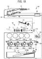
- an image forming apparatus 100 as the fourth variation includes the laminator 50 illustrated in FIG. 17 and an image forming apparatus main body that forms an image on a sheet P.
- multiple pairs of sheet conveying rollers disposed in the document feeder 110 feed the original document D from a document loading table and conveys the original document D in a direction indicated by arrow in FIG. 18 , and the original document D passes over the document reading device 102.
- the document reading device 102 optically reads image data of the original document D passing over the document reading device 102.
- the image data optically read by the document reading device 102 is converted into electric signals and transmitted to a writing device 103.
- the images formed on the photoconductor drums 105Y, 105M, 105C, and 105K are transferred and superimposed onto the intermediate transfer belt 178 to form a color image.
- the color image formed on the intermediate transfer belt 178 is transferred to the surface of a sheet P (which is a sheet to be the insertion sheet PM) fed and conveyed by a feed roller 197 from a feeding device 112 at a position at which the intermediate transfer belt 178 faces the secondary transfer roller 189.
- the sheet P After the color image is transferred onto the surface of the sheet P (that is the insertion sheet PM), the sheet P is conveyed to the position of a fixing device 120.
- the fixing device 120 fixes the transferred color image on the sheet P.
- the sheet P is ejected from the image forming apparatus main body of the image forming apparatus 100 by an ejection roller pair 131 and is fed into the laminator 50 as the insertion sheet PM.
- the laminator 50 including the sheet separation device 1 receives the insertion sheet PM
- the laminator 50 has completed the process described with reference to FIGS. 4A to 7C (that is, the process to separate the two-ply sheet PJ) and performs the process described with reference to FIGS. 8A to 8C (that is, the process to insert the insertion sheet PM into the two-ply sheet PJ) after the laminator 50 (the sheet separation device 1) receives the insertion sheet PM.
- the ejection roller pair 7 ejects the two-ply sheet PJ to the outside of the lamination processor 51 to place the two-ply sheet PJ on the ejection tray 13.
- the image forming apparatus 100 includes the laminator 50, but may include the sheet separation device 1 illustrated in FIG. 1 .
- the image forming apparatus 100 according to the fourth variation is a color image forming apparatus but may be a monochrome image forming apparatus.
- the image forming apparatus 100 according to the fourth variation employs electrophotography, but the present disclosure is not limited to this.
- the present disclosure may be applied to other types of image forming apparatuses such as an inkjet image forming apparatus and a stencil printing machine.
- the image forming apparatus 100 performs the image formation described above with reference to FIG. 17 and ejects the sheet P (that is the insertion sheet formed a desired image) from the ejection roller pair 131 to the laminator 50, and the laminator 50 performs the laminating process on the two-ply sheet PJ into which the insertion sheet PM has been inserted, and the ejection roller pair 7 ejects the two-ply sheet PJ to the outside of the laminator 50 to place the two-ply sheet PJ on the ejection tray 13.
- the sheet P that is the insertion sheet formed a desired image
- the image forming apparatus 100 in the image forming system 200 ejects the sheet P formed the image by the image formation process from a second ejection roller pair 132 to the outside of the image forming apparatus 100 to place the sheet P on a second ejection tray 150.
- the image forming system 200 includes the detachable laminator 50.
- the image forming system 200 may include the sheet separation device 1 illustrated in FIG. 1 detachable.
- the image forming system 200 includes the operation display panel 49.
- the controller determines that the abnormal state occurs based on the results detected by the abnormality detection sensor 46, the controller controls the operation display panel 49 to display that the occurrence of the abnormal state stops the separation operations and the insertion operations of the insertion sheet PM.
- the sheet separation device 1 separates the non-bonding portion of the two-ply sheet PJ in which the two sheets P1 and P2 are overlapped and bonded at one end as the bonding portion A and includes the separation claws 16 as the separator that are inserted into the gap C formed between the two sheets P1 and P2 of the two-ply sheet PJ at a predetermined positions.
- the separation claws 16 guide the two sheets P1 and P2 separated by the separation claws 16 to the two branched conveyance paths K4 and K5 that branch off in different directions, respectively.
- the above-described mechanism can satisfactorily and efficiently separate the two sheets P1 and P2 constituting the two-ply sheet PJ.
- the two branched conveyance paths K4 and K5 branch off in different directions from the third conveyance path K3 between the separation claws 16 as the separator and the winding roller 20.
- the third conveyance path K3 is interposed by the two branched conveyance paths K4 and K5.
- the two branched conveyance paths K4 and K5 may branch off at the position of the separation claws 16 as the separator in different directions from the third conveyance path K3 interposed by the two branched conveyance paths K4 and K5.
- the present disclosure is not limited to the above-described embodiment and variations, and the configuration of the present embodiment can be appropriately modified other than suggested in the above embodiment and variations within a scope of the technological concept of the present disclosure.
- the number, position, and shape of the components described above are not limited to those embodiments described above. Desirable number, position, and shape can be determined to perform the present disclosure.
- the "end surface" of the two-ply sheet is defined as a side surface extending in the thickness direction and connecting the front surface and the back surface of the two-ply sheet. Accordingly, there are four end surfaces of the rectangular two-ply sheet on the front, back, left, and right.
Landscapes
- Engineering & Computer Science (AREA)
- Manufacturing & Machinery (AREA)
- Mechanical Engineering (AREA)
- Folding Of Thin Sheet-Like Materials, Special Discharging Devices, And Others (AREA)
- Lining Or Joining Of Plastics Or The Like (AREA)
Abstract
Description
- This disclosure relates to a sheet separation device configured to separate a two-ply sheet in which two sheets are overlapped and bonded together at a bonding portion of the two-ply sheet, a laminator including the sheet separation device, an image forming apparatus including the sheet separation device, such as a copier, a printer, a facsimile machine, and a multi-functional apparatus having at least two functions of the copier, the printer, and the facsimile machine, and an image forming system including the sheet separation device.
- A sheet separation device (i.e. a laminator) separates a two-ply sheet in which two sheets are overlapped and bonded together at a bonding portion of the two-ply sheet (for example, see
JP-2006-160429-A JP-2006-160429-A - Conventional sheet separation devices are large and expensive because the sheet separation devices use large devices such as two suction devices to separate two sheets constituting a two-ply sheet.
- This disclosure is made in light of solving the above-described problems, and an object of this disclosure is to provide a sheet separation device, a laminator, an image forming apparatus, and an image forming system, which can preferably and effectively separate two sheets constituting the two-ply sheet without increasing the size of the separation device.
- The present disclosure provides a sheet separation device, a laminator, an image forming apparatus, and an image forming system, which can satisfactorily separate ends of the two sheets constituting the two-ply sheet in which two sheets are overlapped and bonded together at one end as a bonding portion of the two-ply sheet without increasing the size of the separation device. In order to achieve this object, there is provided a sheet separation device according to
claim 1. Advantageous embodiments are defined by the dependent claims. - Advantageously, the sheet separation device is configured to separate a non-bonding portion of a two-ply sheet in which two sheets are overlapped and bonded together at one end as a bonding portion of the two-ply sheet. The sheet separation device includes tow branched conveyance paths and a separator. The two branched conveyance paths are branched in different directions. The separator is configured to be inserted into a gap formed between the two sheets of the two-ply sheet, separate the two sheets, and guide the two sheets to the two branched conveyance paths, respectively.
- The present disclosure can provide the sheet separation device, the laminator, the image forming apparatus, and the image forming system, which can preferably and effectively separate the two sheets constituting the two-ply sheet without increasing the size of the separation device.
- A more complete appreciation of the disclosure and many of the attendant advantages thereof will be readily obtained as the same becomes better understood by reference to the following detailed description when considered in connection with the accompanying drawings, wherein:
-
FIG. 1 is a schematic view illustrating an overall configuration of a sheet separation device according to an embodiment of the present disclosure; -
FIG. 2A is a side view illustrating a gripper that has moved to a gripping position in the sheet separation device illustrated inFIG. 1 ; -
FIG. 2B is a side view illustrating the gripper that has moved to a releasing position in the sheet separation device illustrated inFIG. 1 ; -
FIG. 3A is a perspective view illustrating the gripper that has moved to the gripping position in the sheet separation device illustrated inFIG. 1 ; -
FIG. 3B is a perspective view illustrating the gripper that has moved to the releasing position in the sheet separation device illustrated inFIG. 1 ; -
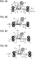
FIGS. 4A to 4D are schematic views of the main part of the sheet separation device illustrated inFIG. 1 , illustrating operations of the sheet separation device; -
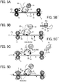
FIGS. 5A to 5D are schematic views of the main part of the sheet separation device illustrated inFIG. 1 , illustrating operations of the sheet separation device, subsequent from the operations ofFIGS. 4A to 4D ; -
FIGS. 6A to 6C are schematic views of the main part of the sheet separation device illustrated inFIG. 1 , illustrating operations of the sheet separation device, subsequent from the operations ofFIGS. 5A to 5D ; -
FIGS. 7A to 7C are schematic views of the main part of the sheet separation device illustrated inFIG. 1 , illustrating operations of the sheet separation device, subsequent from the operations ofFIGS. 6A to 6C ; -
FIGS. 8A to 8C are schematic views of the main part of the sheet separation device illustrated inFIG. 1 , illustrating operations of the sheet separation device, subsequent from the operations ofFIGS. 7A to 7C ; -
FIG. 9 is a schematic view illustrating separation claws inserted into a two-ply sheet in a width direction of the two-ply sheet; -
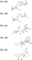
FIGS. 10A to 10E are perspective views illustrating operations of the separation claws; -
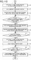
FIG. 11 includingFIGS. 11A and11B is a flowchart illustrating control performed in the sheet separation device; -
FIG. 12 is a schematic view illustrating a configuration of a driving device for the separation claws; -
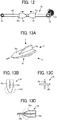
FIG. 13A is a perspective view of the separation claw; -
FIG. 13B is a plan view of the separation claw as viewed from the Z direction inFIG. 13A ; -
FIG. 13C is a rear view of the separation claw as viewed from the Y direction inFIG. 13A ; -
FIG. 13D is a side view of the separation claw as viewed from the X direction inFIG. 13A ; -
FIG. 14A is a perspective view of the separation claw according to a first variation; -
FIG. 14B is a plan view of the separation claw according to the first variation, as viewed from the Z direction inFIG. 14A ; -
FIG. 14C is a rear view of the separation claw as viewed from the Y direction inFIG. 14A ; -
FIG. 14D is a front view of the separation claw according to the first variation as viewed from the - Y direction inFIG. 14A ; -
FIG. 14E is a side view of the separation claw according to the first variation as viewed from the X direction inFIG. 14A ; -
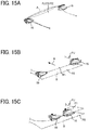
FIGS. 15A to 15C are perspective views illustrating operations of the separation claw inFIGS. 14A to 14E ; -
FIG. 16 is a schematic view illustrating a configuration of a driving device for the separation claws in a second variation; -
FIG. 17 is a schematic view illustrating a laminator according to a third variation; -
FIG. 18 is a schematic view illustrating an image forming apparatus according to a fourth variation; and -
FIG. 19 is a schematic view illustrating an image forming system according to a fifth variation. - The accompanying drawings are intended to depict embodiments of the present disclosure and should not be interpreted to limit the scope thereof. The accompanying drawings are not to be considered as drawn to scale unless explicitly noted. Also, identical or similar reference numerals designate identical or similar components throughout the several views.
- In describing embodiments illustrated in the drawings, specific terminology is employed for the sake of clarity. However, the disclosure of this patent specification is not intended to be limited to the specific terminology so selected and it is to be understood that each specific element includes all technical equivalents that operate in a similar manner and achieve similar results.
- Referring now to the drawings, embodiments of the present disclosure are described below. As used herein, the singular forms "a," "an," and "the" are intended to include the plural forms as well, unless the context clearly indicates otherwise. Identical reference numerals are assigned to identical components or equivalents and a description of those components is simplified or omitted.
- A configuration and operations of a
sheet separation device 1 are described below with reference toFIG. 1 . - The
sheet separation device 1 separates a non-bonding portion of a two-ply sheet PJ in which two sheets P1 and P2 are overlapped and bonded together at one end of the two-ply sheet PJ as a bonding portion A of the two-ply sheet PJ (seeFIGS. 10A to 10E and other drawings). - The two-ply sheet PJ in the present embodiment is made of two sheets P1 and P2 overlapped and bonded together at one side of four sides as the bonding portion A. That is, in the two-ply sheet PJ made of two sheets P1 and P2, only one sides of the two sheets P1 and P2 are connected by thermal welding or the like as the bonding portion A, and the other sides of the two sheets P1 and P2 are not connected. As the two sheets P1 and P2 constituting the two-ply sheet PJ, a transparent film sheet (that is, a laminate sheet) may be used.
- The
sheet separation device 1 separates the two sheets P1 and P2 constituting the tow-ply sheet PJ (i.e. separates the other side of the two sheets that is opposite the bonding portion A that maintains bonding the two sheets P1 and P2). Subsequently, thesheet separation device 1 inserts an insertion sheet PM between the separated two sheets P1 and P2. The insertion sheet PM is a sheet such as one plain sheet or a photograph. - As illustrated in
FIG. 1 , thesheet separation device 1 includes afirst feed tray 11, asecond feed tray 12, afirst feed roller 2, asecond feed roller 3, a first conveyance roller pair 4, a secondconveyance roller pair 5, a thirdconveyance roller pair 6, anejection tray 13, a first sensor 41, asecond sensor 42, athird sensor 43, afourth sensor 44, afifth sensor 45, anabnormality detection sensor 46 as an abnormal detection device, a windingroller 20, a movingmechanism 30, and aseparation claw 16 as a separator (seeFIGS. 6B to 6C ,FIGS. 10A to 10E , or the like). - Additionally, the
sheet separation device 1 includes a plurality of conveyance paths such as a first conveyance path K1, a second conveyance path K2, a third conveyance path K3, a first branched conveyance path K4, and a second branched conveyance path K5. The above-described conveyance paths K1 to K5 each include two conveyance guide plates facing each other to guide and convey the sheet such as the two-ply sheet PJ or the insertion sheet PM. - Specifically, the two-ply sheet PJ is stacked on the
first feed tray 11. Thefirst feed roller 2 feeds the uppermost two-ply sheet PJ on thefirst feed tray 11 to the first conveyance roller pair 4, and the first conveyance roller pair 4 conveys the two-ply sheet PJ to the first conveyance path K1. - The insertion sheet PM is stacked on the
second feed tray 12. Thesecond feed roller 3 feeds the uppermost insertion sheet PM on thesecond feed tray 12 to the second conveyance path K2. - Each of the first to third conveyance roller pairs 4 to 6 includes a drive roller and a driven roller, and conveys the sheet nipped by the nips. The third conveyance path K3 includes, from the upstream side, the second
conveyance roller pair 5, the windingroller 20, and the thirdconveyance roller pair 6. The windingroller 20 and the thirdconveyance roller pair 6 is configured to be able to rotate in forward or in reverse. The thirdconveyance roller pair 6 can convey the sheet in the forward direction that is the left direction inFIG. 1 and in the reverse direction that is the right direction inFIG. 1 . The thirdconveyance roller pair 6 also functions as an ejection roller pair that ejects the sheet to theejection tray 13. - Each of the first to fifth sensors 41 to 45 as a sheet detection sensor is a reflective photosensor that optically detects whether the sheet is present at the position of each sensor. The first sensor 41 is disposed in the vicinity of the downstream side of the first conveyance roller pair 4. The
second sensor 42 is disposed in the vicinity of the downstream side of thesecond feed roller 3. Thethird sensor 43 is disposed in the vicinity of the downstream side of the secondconveyance roller pair 5. Thefourth sensor 44 is disposed in the vicinity of the downstream side of the winding roller 20 (that is the left side of the windingroller 20 inFIG. 1 ) and the upstream side of the third conveyance roller pair 6 (that is the right side of the thirdconveyance roller pair 6 inFIG. 1 ). Thefifth sensor 45 is disposed downstream the third conveyance roller pair 6 (that is the left side of the thirdconveyance roller pair 6 inFIG. 1 ). - With reference to
FIGS. 2A, 2B ,3A, 3B ,5B to 5D , and6A , the windingroller 20 is described. In the windingroller 20, agripper 32 that is one example of a gripper grips a gripped portion B of the two-ply sheet PJ at a winding start position W (seeFIG. 5B ). The gripped portion B is an end of the two-ply sheet PJ that is opposite an end at which the bonding portion A is formed, which is referred to as the other end of the two-ply sheet PJ. While thegripper 32 grips the gripped portion B of the two-ply sheet PJ, the windingroller 20 rotates in a predetermined rotation direction (counterclockwise inFIG. 5B ) to wrap the two-ply sheet PJ around the windingroller 20. - The winding
roller 20 can rotate about arotation shaft 20a in forward and in reverse. A controller controls a drive motor that drives the windingroller 20. The controller includes one or more processing circuits or circuitry. Processing circuitry includes a programmed processor, as a processor includes circuitry. A processing circuit also includes devices such as an application specific integrated circuit (ASIC), a digital signal processor (DSP), a field programmable gate array (FPGA), and conventional circuit components. - Specifically, the two-ply sheet PJ starts from the
first feed tray 11 and passes through the first conveyance path K1, and the secondconveyance roller pair 5 conveys the two-ply sheet PJ in the forward direction along the third conveyance path K3. The two-ply sheet PJ passes through the winding start position W of the windingroller 20 once and is conveyed to a position of the thirdconveyance roller pair 6 that is a position at which the back end of the two-ply sheet PJ passes through thefourth sensor 44 but does not pass through the thirdconveyance roller pair 6, that is, the position in front of the thirdconveyance roller pair 6. - Thereafter, the third
conveyance roller pair 6 rotates in reverse to convey the two-ply sheet PJ in the reverse direction to the position of the windingroller 20 that is the winding start position W, and thegripper 32 grips the two-ply sheet PJ. The gripped two-ply sheet PJ is further conveyed, and the windingroller 20 rotates counterclockwise inFIG. 1 to wrap the two-ply sheet PJ around the windingroller 20. - With reference to
FIG. 5C' , when the two-ply sheet PJ is wound around the windingroller 20, a length of a sheet wound around the windingroller 20 is proportional to a distance from the center of the windingroller 20 to the sheet. Therefore, since a first sheet P1 is nearer to the center of the windingroller 20 than a second sheet P2, a length of the first sheet P1 wound around the windingroller 20 is shorter than a length of the second sheet P2 wound around the windingroller 20. As a result, misalignment occurs in a part of the two-ply sheet PJ in which the sheet P1 is in close contact with the sheet P2 (in other words, the part in which the sheet P1 sticks to the sheet P2) other than the bonding portion A and the gripped portion B. As illustrated inFIGS. 5D and6A , the misalignment causes the upper first sheet P1 to slack and bend upward and forms a gap C between the two sheets P1 and P2 in the vicinity of the bonding portion A that is referred to as one end of the two-ply sheet PJ. As described above, the two sheets P1 and P2 that are in close contact with each other without any gap are separated from each other. - In the present embodiment, in order to significantly form the gap C as described above, that is, to increase the difference between lengths of the sheets P1 and P2 wound around the winding
roller 20, the two-ply sheet PJ is wound around the windingroller 20 at least once or more. - Thus, in the present embodiment, winding the two-ply sheet PJ around the winding
roller 20 can separate the two-ply sheet PJ without increasing the size and cost of thesheet separation device 1. - As illustrated in
FIG. 5B' , thegripper 32 in the present embodiment is configured to grip the gripped portion B of the two-ply sheet PJ without contacting the end surface of the other end of the gripped portion B on any member. - Specifically, the
gripper 32 is configured to sandwich and grip the gripped portion B of the two-ply sheet PJ between thegripper 32 and a receivingportion 20b of the windingroller 20 without causing any member to abut and restrict the end surface of the other end of the two-ply sheet PJ, in other words, without causing any member to hit or contact the end surface of the two-ply sheet PJ. The receivingportion 20b is a part of an outer circumferential portion of the windingroller 20 and faces thegripper 32. - More specifically, the two-ply sheet PJ is not gripped and sandwiched by the
gripper 32 and the receivingportion 20b in a state in which a specific member such as thegripper 32 abuts on the end surface of the other end (that is the tip of the other end). Without abutting the end surface of the other end that is the tip of the other end to any member, the two-ply sheet PJ is sandwiched and gripped by theouter gripper 32 and theinner receiving portion 20b. - Compared with a structure that abuts the end surface of the tip of the two-ply sheet PJ on a member, the above-described structure can reduce a disadvantage that the two-ply sheet PJ (particularly, the tip of the other end) is damaged. Since a part of the two-ply sheet PJ including a damaged front end surface is hard for the laminating process, the configuration of the present disclosure is useful.
- In the present embodiment, the bonding portion A of the two-ply sheet PJ wound around the winding
roller 20 is the one end of the two-ply sheet PJ. The one end is opposite to the other end serving as the gripped portion B. - In the present embodiment, at least one of the
gripper 32 and the receivingportion 20b is made of elastic material such as rubber. - Compared with a sheet separation device including the
gripper 32 and the receivingportion 20b that are rigid bodies made of metal or resin, the above-described sheet separation device can increase a gripping force to grip the two-ply sheet PJ and prevent surfaces of the two-ply sheet PJ from being damaged. In particular, the sheet separation device including thegripper 32 and the receivingportion 20b made of the elastic material easily exhibits the above-described effect. - As illustrated in
FIGS. 2A to 3B , the movingmechanism 30 moves thegripper 32 between a gripping position (a position illustrated inFIGS. 2A and3A ) at which thegripper 32 can grip the two-ply sheet PJ and a releasing position (a position illustrated inFIGS. 2B and3B ) at which thegripper 32 is released from the gripping position. - Specifically, the moving
mechanism 30 includes anarm 31, acompression spring 33 as a biasing member, acam 34, and a motor that rotates thecam 34 in forward or in reverse. - The
arm 31 holds thegripper 32, and thearm 31 and thegripper 32 are held together by the windingroller 20 to be rotatable about asupport shaft 31a. In the present embodiment, thegripper 32 is connected to the tip ofarm 31, and thegripper 32 and thearm 31 are made as one part. Alternatively, thegripper 32 and thearm 31 may be made as separate members, and thegripper 32 may be disposed on thearm 31, that is, may be held by thearm 31. In any case, thearm 31 holding thegripper 32 rotates around therotation shaft 20a together with the windingroller 20. - The
compression spring 33 functions as a biasing member that biases thearm 31 so that thegripper 32 moves from the releasing position illustrated inFIG. 2B to the gripping position illustrated inFIG. 2A . Specifically, one end of thecompression spring 33 is connected to a fixed part near therotation shaft 20a, and the other end thecompression spring 33 is connected to one end of thearm 31 that is an end opposite to the other end of thearm 31 connected to thegripper 32 with respect to thesupport shaft 31a. - The
cam 34 pushes thearm 31 against the biasing force of thecompression spring 33 as the biasing member so that thegripper 32 moves from the gripping position illustrated inFIG. 2A to the releasing position illustrated inFIG. 2B . A motor controlled by the controller drives thecam 34 to rotate in forward or in reverse at a desired rotation angle. Thecam 34 is held by a housing of thesheet separation device 1 so as to be rotatable about acam shaft 34a independently of the windingroller 20. - In the moving
mechanism 30 configured as described above, as illustrated inFIGS. 2A and3A , thearm 31 not contacting thecam 34 is biased by thecompression spring 33 and presses thegripper 32 against the receivingportion 20b. This state is referred to as a closed state. In the closed state, thegripper 32 and the receivingportion 20b can grip the two-ply sheet PJ. - In contrast, as illustrated in
FIGS. 2B and3B , thearm 31 pressed by thecam 34 rotates counterclockwise inFIG. 2B about thesupport shaft 31a against the urging force of thecompression spring 33 and separates thegripper 32 from the receivingportion 20b. This state is referred to as an open state. In the open state, the two-ply sheet PJ is not gripped, which is referred to as a grip release state. - In the present embodiment, as illustrated in
FIGS. 3A and 3B , the windingroller 20 includes a plurality of roller portions (i.e. seven roller portions in the present embodiment) separated in the axial direction of the windingroller 20. Corresponding to the roller portions, thecam 34 includes a plurality of portions separated in the axial direction. - Setting portions separated in the axial direction to grip the two-ply sheet PJ as described above, that is, not setting entire area in the axial direction to grip the two-ply sheet PJ can share load necessary to grip the two-ply sheet PJ. The above-described configuration is useful when a necessary gripping force becomes large.
- With reference to
FIGS. 1 ,4D , and5A , the following describes thefourth sensor 44 in thesheet separation device 1 in the present embodiment. Thefourth sensor 44 is the sheet detection sensor to detect two-ply sheet PJ conveyed between the windingroller 20 and the thirdconveyance roller pair 6. Thefourth sensor 44 detects the front end of the two-ply sheet PJ conveyed to the windingroller 20 by the thirdconveyance roller pair 6. Based on results detected by thefourth sensor 44, the controller controls the movingmechanism 30. - Specifically, the
fourth sensor 44 is disposed on the conveyance path between the windingroller 20 and the thirdconveyance roller pair 6. As illustrated inFIGS. 4D and5A , the thirdconveyance roller pair 6 conveys the two-ply sheet PJ in the reverse direction toward the position of the windingroller 20, so that the gripped portion B of the two-ply sheet PJ becomes a front end in the reverse direction conveyance, and thefourth sensor 44 detects the front end of the two-ply sheet PJ conveyed in the reverse direction, that is, the tip of one end of the gripped portion B. The controller uses a timing at which thefourth sensor 44 detects the tip of one end of the gripped portion B as a trigger to adjust and control a timing to stop the two-ply sheet PJ at the gripping position and a timing at which thegripper 32 grips the gripped portion B. Specifically, after a predetermined time has passed since thefourth sensor 44 detected the front end of the two-ply sheet PJ, the thirdconveyance roller pair 6 stops the reverse direction conveyance of the two-ply sheet PJ, and thecam 34 rotates to pivot thearm 31 of the movingmechanism 30 so that thegripper 32 moves from the releasing position illustrated inFIG. 2B to the gripping position illustrated inFIG. 2A . - The above-described control accurately performs an operation in which the end surface of the two-ply sheet PJ is sandwiched by the
gripper 32 and the receivingportion 20b without abutting the end surface of the two-ply sheet PJ on any member. - As described above, the third
conveyance roller pair 6 conveys the other end (i.e. the gripped portion B) of the two-ply sheet PJ as a front end toward the winding start position W of the windingroller 20 in the third conveyance path K3 between the thirdconveyance roller pair 6 and the windingroller 20. - With reference to
FIGS. 6A to 6C ,9 ,10A to 10E , and12 , theseparation claws 16 as a separator are described. Theseparation claws 16 are claw-shaped members that move from standby positions illustrated inFIG. 10A and are inserted into the gap C formed between two sheets P1 and P2 at a predetermined position of the two-ply sheet PJ. The predetermined position is a position at which theseparation claws 16 as the separator can enter the gap formed between the two sheets P1 and P2 and is determined by experiments. Preferably, the gap formed between the two sheets P1 and P2 becomes largest at the predetermined position in thesheet separation device 1. - Specifically, the
separation claws 16 are inserted into the gap C formed between two sheets P1 and P2 at a position between the windingroller 20 and the thirdconveyance roller pair 6 from the standby positions outside both ends of the two-ply sheet PJ in the width direction of the two-ply sheet PJ in which the other end (that is the gripped portion B) is wound by the windingroller 20 and the one end (that is the bonding portion A) is nipped by the thirdconveyance roller pair 6. - More specifically, in the present embodiment, the
separation claws 16 are a pair of separation claws as a pair of separators disposed at both sides of the third conveyance path K3 in the width direction that is the direction perpendicular to a plane on whichFIGS. 6A to 6C are illustrated and the horizontal direction inFIGS. 9 and12 . - As illustrated in
FIGS. 10A to 10E , and13A to 13D , the vertical length of theseparation claw 16 in the thickness direction of the two-ply sheet PJ gradually increases from the tip to the end of theseparation claw 16. Theseparation claws 16 is moved in the width direction of the two-ply sheet PJ by driving device 76 (seeFIG. 12 ) controlled by the controller. - The
separation claws 16 configured as described above ordinarily stand by at standby positions at which theseparation claws 16 do not interfere with the conveyance of the sheet such as the two-ply sheet PJ in the third conveyance path K3. As illustrated inFIG. 10A , the standby positions are outside of the sheet P in the width direction of the sheet P. Subsequently, as illustrated inFIGS. 9 and10B , theseparation claws 16 enter the gap C in the two-ply sheet PJ when the two-ply sheet PJ (configured by two sheets P1 and P2) is separated. As a result, theseparation claws 16 secure the gap C to be large. - As illustrated in
FIG. 12 , the drivingdevice 76 moves the pair ofseparation claws 16 in the width direction and includes amotor 77, agear pulley 78, apulley 79, atiming belt 80. - The
gear pulley 78 has a step-like ring shape including a gear that meshes with a motor gear disposed on a motor shaft of themotor 77 and a pulley that stretches and supports thetiming belt 80 together with thepulley 79. Oneseparation claw 16 of the pair ofseparation claws 16 includes the fixedportion 16a fixed to the belt surface of the timing belt 64 that is the upper side of the belt surface inFIG. 15 , and theother separation claw 16 includes the fixedportion 16a fixed to the other belt surface of the timing belt 64 that is the lower side of the belt surface inFIG. 15 . - In the driving
device 76 as configured described above, themotor 77 drives to rotate the motor shaft in a direction indicated by arrow inFIG. 12 (i.e. clockwise), thegear pulley 78 rotates counterclockwise, thetiming belt 80 rotates counterclockwise, and the pair ofseparation claws 16 moves from the outside portions in the width direction to the center portion in the width direction (that is, the pair ofseparation claws 16 approaches each other). In contrast, when themotor 77 drives to rotate the motor shaft in the direction opposite to the arrow direction inFIG. 12 , the pair ofseparation claws 16 moves from the center portion in the width direction toward the outside portions in the width direction (that is, the pair of theseparation claws 16 moves in a direction away from each other). - The
separation claws 16 are inserted into the gap C in the two-ply sheet PJ, relatively move from the one end of the two-ply sheet PJ near the bonding portion A to the other end of the two-ply sheet PJ near the gripped portion B, and subsequently move in the width direction between the two sheets P1 and P2 at the other end of the two-ply sheet PJ. - Specifically, the controller controls a driving device 76 (see
FIG. 12 ) to move the pair ofseparation claws 16 as follows. As illustrated inFIGS. 10B and 10C , the pair ofseparation claws 16 is inserted into the both ends of the gap C in the two-ply sheet PJ in the width direction and relatively moves to the other end of the two-ply sheet PJ that is the gripped portion B. After the pair ofseparation claws 16 reaches to the other end of the two-ply sheet PJ, as illustrated inFIG. 10D , the pair ofseparation claws 16 on the other end of the two-ply sheet PJ moves in the width direction from the both ends of the two-ply sheet PJ to the center of the two-ply sheet PJ between the two sheets P1 and P2. To enable the above-described operations of the pair ofseparation claws 16, the drivingdevice 76 is configured so that the pair ofseparation claws 16 can move from the standby positions to positions at which the pair ofseparation claws 16 is close to each other. - The above-described mechanism including the winding
roller 20 winding the two-ply sheet PJ and theseparation claws 16 inserted into the two-ply sheet PJ to separate the two-ply sheet PJ can reduce the size of the sheet separation device as compared with a mechanism using a large-scale device such as a vacuum device to separate the two-ply sheet PJ. That is, without increasing the size of thesheet separation device 1, the above-described mechanism can satisfactorily separate the two sheets P1 and P2 constituting the two-ply sheet PJ. - In particular, since the
separation claws 16 in the present embodiment move over substantially an entire region of the two-ply sheet PJ on the other end of the two-ply sheet PJ (that is the back end of the two-ply sheet PJ), theseparation claws 16 can sufficiently separate (in other words, peel) the other end of the two sheets P1 and P2 constituting the two-ply sheet PJ that is opposite the bonding portion A. The above-described configuration prevents a disadvantage that the other end of the two-ply sheet PJ that is opposite the bonding portion A is not sufficiently separated and the insertion sheet PM (seeFIG. 10E ) cannot be inserted into the other end of the two-ply sheet PJ. Additionally, the above-described configuration allows theseparation claws 16 as a divider to easily function, that is, separately guide the two sheets P1 and P2 to the two branched conveyance paths K4 and K5. The function of theseparation claws 16 as the divider is described below. - With reference to
FIGS. 7A to 7C , theseparation claws 16 as the divider are described. Theseparation claws 16 also function as the divider that guides the two sheets P1 and P2 separated by theseparation claws 16 to the two branched conveyance paths K4 and K5 that branch off in different directions, respectively. - Specifically, as illustrated in
FIG. 7C , the two branched conveyance paths K4 and K5 branch off in different directions from the third conveyance path K3 between theseparation claws 16 and the windingroller 20. In other words, the third conveyance path K3 is interposed by the two branched conveyance paths K4 and K5. The first branched conveyance path K4 branches upward from the third conveyance path K3, and the second branched conveyance path K5 branches downward from the third conveyance path K3. - As illustrated in
FIGS. 7A to 7C , the thirdconveyance roller pair 6 conveys the one end of the two-ply sheet PJ to the left side inFIG. 7A after theseparation claws 16 are inserted into the gap C until the winding of the other end of the two-ply sheet PJ on the windingroller 20 is released (seeFIGS. 10A to FIG. 10C ). After the winding of the other end of the two-ply sheet PJ on the windingroller 20 is released, theseparation claws 16 move to a center portion of the two-ply sheet PJ as illustrated inFIG. 10D and stop at the center portion, and the thirdconveyance roller pair 6 conveys the other end of the two-ply sheet PJ to the right side inFIG. 7 again. Then, theseparation claws 16 guide the two sheets P1 and P2 separated by theseparation claws 16 to the two branched conveyance paths K4 and K5, respectively. As a result, the first sheet P1 is guided to the first branched conveyance path K4, and the second sheet P2 is guided to the second branched conveyance path K5. Subsequently, as illustrated inFIGS. 8A to 8C and10E , theseparation claws 16 move to the standby positions, and the secondconveyance roller pair 5 conveys the insertion sheet PM to the third conveyance path K3, that is, the right side inFIGS. 8A to 8C to insert the insertion sheet PM between the two sheets P1 and P2 separated from the two-ply sheet PJ. - As described above, the
separation claws 16 in the present embodiment functions as a separator that separates (in other words, peels) the non-bonding portion of the two-ply sheet PJ configured by the two sheets P1 and P2, and also functions as a divider that separately guides the separated two sheets P1 and P2 to the two branched conveyance paths K4 and K5, respectively. Accordingly, the above-described configuration can reduce the size and cost of thesheet separation device 1 compared to the sheet separation device including both the separator and the divider. That is, the above-described configuration can satisfactorily separate the two sheets P1 and P2 constituting the two-ply sheet PJ. - With reference to
FIG. 13 , theseparation claw 16 according to the present embodiment as the separator is more specifically described. Theseparation claw 16 includes afirst plate 16b and asecond plate 16c. The thickness direction of thefirst plate 16b is substantially the same as the thickness direction of the two-ply sheet PJ. Thesecond plate 16c intersects thefirst plate 16b in the thickness direction of thefirst plate 16b. Thefirst plate 16b and thesecond plate 16c are formed as one part. -
FIG. 13A is a perspective view of theseparation claw 16. InFIG. 13A , theseparation claw 16 moves in a direction indicated by a white arrow, that is, moves toward the gap C in the two-ply sheet PJ.FIG. 13C is a rear view of theseparation claw 16 viewed from y direction inFIG. 13A . As illustrated inFIG. 13C , theseparation claw 16 has a substantially cross shape configured by thefirst plate 16b extending in the lateral direction inFIG. 13C that is a conveyance direction of the two-ply sheet PJ and thesecond plate 16c extending in the vertical direction that is a direction in which the gap C is formed. - As illustrated in
FIG. 10D , thesecond plate 16c extending in the thickness direction of the two-ply sheet PJ (that is the direction in which the gap C is formed) as described above can enlarge the distance between the two sheets P1 and P2 by at least a vertical length of thesecond plate 16c when theseparation claw 16 enters between the two sheets P1 and P2. As a result, theseparation claws 16 can easily guide the two sheets P1 and P2 to the two branched conveyance paths K4 and K5, respectively. That is, the function of theseparation claw 16 as the divider is easily exhibited. - As illustrated in
FIG. 13D , theseparation claw 16 includes a tapered portion 16c1. A length of the tapered portion 16c1 in the thickness direction of the two-ply sheet PJ (that is the vertical direction inFIG. 13D ) gradually increases outward in the width direction of the two-ply sheet PJ. - Specifically, as illustrated in
FIGS. 13A, 13B, and 13D , the tip of thesecond plate 16c near the center of the two-ply sheet PJ in the width direction of the two-ply sheet PJ is positioned further outward in the width direction of the two-ply sheet PJ than the tip of thefirst plate 16b near the center of the two-ply sheet PJ in the width direction of the two-ply sheet PJ. In addition, the back end of thesecond plate 16c that is an outer end of thesecond plate 16c in the width direction of the two-ply sheet PJ is the same position in the width direction of the two-ply sheet PJ as the back end of thefirst plate 16b that is an outer end of thefirst plate 16b in the width direction of the two-ply sheet PJ. The tapered portion 16c1 extends in a horizontal direction inFIG. 13D from the tip of thesecond plate 16c near the center of the two-ply sheet PJ in the width direction of the two-ply sheet PJ and gradually increases the vertical length from the left to the right inFIG. 13D . - More specifically, the
second plate 16c has an upper trapezoidal portion and a lower trapezoidal portion that sandwich thefirst plate 16b as illustrated inFIG. 13D . - The
second plate 16c (that is, the separation claw 16) including the tapered portion 16c1 as described above prevents a disadvantage that theseparation claw 16 is caught by the sheet P1 or P2 when theseparation claw 16 enters into the gap C in the two-ply sheet PJ from the standby position as illustrated inFIGS. 10A and 10B . That is, theseparation claw 16 smoothly enters the gap C in the two-ply sheet PJ, and thesecond plate 16c separates the two sheets P1 and P2 at a sufficient interval. - As illustrated in
FIG. 13B , theseparation claw 16 includes a tapered portion 16b1. A length of the tapered portion 16b1 in the conveyance direction of the two-ply sheet PJ (that is the horizontal direction inFIG. 13B ) gradually increases outward in the width direction of the two-ply sheet PJ. - Specifically, as illustrated in
FIGS. 13A, 13B, and 13D , the tip of thefirst plate 16b near the center of the two-ply sheet PJ in the width direction of the two-ply sheet PJ is positioned nearer to the center of the two-ply sheet PJ in the width direction of the two-ply sheet PJ than the tip of thesecond plate 16c near the center of the two-ply sheet PJ in the width direction of the two-ply sheet PJ. - The tapered
portion 16bFIG. 13B from the tip of thefirst plate 16b near the center of the two-ply sheet PJ in the width direction of the two-ply sheet PJ, and a length of the taperedportion 16bFIG. 13B . - More specifically, as illustrated in
FIG. 13B , the tip of thefirst plate 16b is substantially V-shaped. - The
first plate 16b (that is, the separation claw 16) including the taperedportion 16bseparation claw 16 is caught by an end of the tow-ply sheet PJ forming a gap C in the width direction of the two-ply sheet PJ when theseparation claw 16 enters into the gap C in the two-ply sheet PJ from the standby position as illustrated inFIGS. 10A and 10B . That is, theseparation claw 16 smoothly enters the gap C in the two-ply sheet PJ, increases the width of the gap C, and separates the two sheets P1 and P2. - With reference to
FIGS. 6A to 6C , thefirst guide 25 is described below. Thefirst guide 25 is disposed between theseparation claws 16 and the windingroller 20 in the third conveyance path K3 and functions as a limiter to limit an amount of slack (in other words, a deflection amount) of the first sheet P1 that is an inner sheet of the two sheet P1 and P2 of the two-ply sheet PJ wound around the windingroller 20. - Specifically, the
first guide 25 as the limiter is a conveyance guide disposed on the side in which the windingroller 20 is disposed with respect to an imaginary plane S1, that is, above the imaginary plane S1 inFIG. 6A , in the third conveyance path. The imaginary plane S1 is an imaginary plane passing through the winding start position W of the windingroller 20 and the nip of the thirdconveyance roller pair 6 in the third conveyance path (seeFIG. 6A ). Thefirst guide 25 has a shape like a triangular prism having a plane along the outer circumferential surface of the windingroller 20, and the plane covers a part of the outer circumferential surface of the windingroller 20 and is separated from the windingroller 20 by a predetermined gap. Thefirst guide 25 functions as a conveyance guide of the third conveyance path K3 and a conveyance guide of the first branched conveyance path K4. That is, thefirst guide 25 guides the sheet conveyed on the third conveyance path K3, the sheet conveyed on the first branched conveyance path K4, and the sheet wound around the windingroller 20. - In the third conveyance path K3, the
first guide 25 limits bending the two-ply sheet PJ upward (in particular, bending the first sheet P1 upward) between the windingroller 20 and the thirdconveyance roller pair 6. Therefore, the gap C in the two-ply sheet PJ that is mainly formed by bending the first sheet P1 upward is intensively formed between thefirst guide 25 and the thirdconveyance roller pair 6. Accordingly, the above-described configuration can increase the size of the gap C even if the winding amount of the two-ply sheet PJ wound around the windingroller 20 is not large, and theseparation claws 16 can smoothly enter the gap C to separate the two-ply sheet PJ. - With reference to
FIGS. 6 A to 6 C , thesecond guide 26 is described below. Thesecond guide 26 is disposed between theseparation claws 16 and the windingroller 20 in the third conveyance path K3 and functions as a guide to guide the second sheet P2 that is an outer sheet of the two sheet P1 and P2 of the two-ply sheet PJ wound around the windingroller 20. - Specifically, the
second guide 26 as the guide is a conveyance guide disposed on the side in which the windingroller 20 is not disposed with respect to the imaginary plane S1, that is, below the imaginary plane S1 inFIG. 6A , in the third conveyance path. Thesecond guide 26 is disposed to face the lower surface of the sheet from a portion upstream from the secondconveyance roller pair 5 to a portion downstream from the thirdconveyance roller pair 6 in the forward direction. That is, thesecond guide 26 guides the sheet conveyed on the third conveyance path K3. - In the third conveyance path K3 between the winding
roller 20 and the thirdconveyance roller pair 6, a clearance between thefirst guide 25 and thesecond guide 26 is set to be a value by which the sheet having the largest thickness can be conveyed to limit a gap between the sheets P1 and P2 of the two-ply sheet PJ between thefirst guide 25 and thesecond guide 26 not to be too large. Therefore, the gap C in the two-ply sheet PJ that is mainly formed by bending the first sheet P1 upward is intensively formed between an end of thefirst guide 25 and the thirdconveyance roller pair 6. Accordingly, theseparation claws 16 can smoothly enter the gap C to separate the two-ply sheet PJ. - With reference to
FIGS. 6A to 6C , theabnormality detection sensor 46 is described below. Theabnormality detection sensor 46 functions as an abnormality detection device to detect an abnormal state in which the gap C formed between the two sheets P1 and P2 at a predetermined position (that is between the thirdconveyance roller pair 6 and the winding roller 20) is not larger than a predetermined size before movements of theseparation claws 16 from the standby positions (that is, movements from the standby positions illustrated inFIG. 10A to separation positions illustrated inFIGS. 9 and10B ). The predetermined size is a size of the gap C into which theseparation claws 16 can enter and is determined by experiments. That is, theabnormality detection sensor 46 as the abnormality detection device detects the abnormal state in which the gap C formed between the two sheets P1 and P2 at a predetermined position is not larger than the predetermined size before theseparation claws 16 are inserted into the gap C. - In other words, at a timing at which the gap C is formed between the two sheets P1 and P2 as illustrated in
FIGS. 5D and6A , theabnormality detection sensor 46 as the abnormality detection device detects the abnormal state such as a state in which the gap is not formed at all or a state in which the gap is not formed as a sufficient gap C. - In the present embodiment, the controller notifies the occurrence of the abnormal state when the abnormal state is detected by the
abnormality detection sensor 46 that is the abnormality detection device. Specifically, as illustrated inFIG. 1 , thesheet separation device 1 includes anoperation display panel 49 as an operation display device on the exterior of thesheet separation device 1 to display various kinds of information about thesheet separation device 1 and input various kinds of commands. When the controller determines that the abnormal state occurs based on the results detected by theabnormality detection sensor 46, that is, when the two-ply sheet PJ does not have the sufficiently large gap C, the controller controls theoperation display panel 49 to display that the abnormal state is detected. For example, theoperation display panel 49 displays "Since an abnormality has occurred, the process of inserting the insertion sheet is stopped. Please check the setting direction of the two-ply sheet in the first feed tray. If the setting direction is correct and similar abnormalities are repeated, please contact a service person. ". - The above-described
abnormality detection sensor 46 as the abnormality detection device may be a lever type sensor that comes into contact with the upper first sheet P1 of the two-ply sheet PJ forming the gap C larger than the predetermined size or other type sensors. - With reference to
FIGS. 4A to 8C , the following describes operations of thesheet separation device 1 to separate the two-ply sheet PJ. - In the description of the operations, operations of the
separation claws 16 is appropriately described with reference toFIGS. 9 to 10E , and the control flow is described with reference to a flowchart ofFIG. 11 , that is,FIGS. 11A and11B . - After the
first feed roller 2 and the first conveyance roller pair 4 start feeding the two-ply sheet PJ from thefirst feed tray 11 in step S1 ofFIG. 11A , as illustrated inFIG. 4A , the secondconveyance roller pair 5 conveys the two-ply sheet PJ with the bonding portion A as a front end in the forward direction that is a direction from the right side to the left side inFIG. 4A in the third conveyance path K3. - At this time, the controller controls the moving
mechanism 30 so that thegripper 32 is positioned at the gripping position. That is, thecam 34 moves to a rotational position at which thecam 34 does not push thearm 31. When thegripper 32 is positioned at the gripping position as described above, thegripper 32 does not interfere the sheet conveyance in the third conveyance path K3. Theseparation claws 16 stand by at the standby positions (illustrated inFIG. 10A ) at which theseparation claws 16 do not interfere with the conveyance of the sheets in the third conveyance path K3. Subsequently, the controller determines whether thethird sensor 43 detects the bonding portion A of the two-ply sheet PJ (that is a front end of the two-ply sheet PJ conveyed in the forward direction and the one end of the two-ply sheet PJ) in step S2 ofFIG. 11A . - The controller uses a timing at which the
third sensor 43 detects the bonding portion A as a trigger and, as illustrated inFIG. 4B , the controller controls the thirdconveyance roller pair 6 to convey the two-ply sheet PJ in the forward direction by a predetermined amount X1 until the gripped portion B of the two-ply sheet PJ (that is the other end of the two-ply sheet PJ and a back end of the two-ply sheet PJ conveyed in the forward direction) passes through the position of the windingroller 20 in step S3 ofFIG. 11A . - As illustrated in
FIG. 4C , the controller temporarily stops the thirdconveyance roller pair 6 to stop the conveyance of the two-ply sheet PJ conveyed by the predetermined amount X1 and controls thegripper 32 to move from the gripping position to the releasing position in step S4 ofFIG. 11A . That is, thecam 34 moves to a rotational position at which thecam 34 pushes thearm 31. In this state, the gripped portion B of the two-ply sheet PJ can be received between thegripper 32 and the receivingportion 20b. - Then, as illustrated in
FIG. 4D , the thirdconveyance roller pair 6 rotates in reverse to start conveyance of the two-ply sheet PJ in the reverse direction in step S5 ofFIG. 11A . At this time, thefourth sensor 44 detects the gripped portion B of the two-ply sheet PJ that is the other end of the two-ply sheet PJ and the front end of the two-ply sheet PJ conveyed in the reverse direction. - Subsequently, as illustrated in
FIG. 5A , the controller uses the timing at which thefourth sensor 44 detects the gripped portion B of the two-ply sheet PJ as a trigger in step S6 ofFIG. 11A and stops the conveyance of the two-ply sheet PJ in step S7 ofFIG. 11A at a timing at which the thirdconveyance roller pair 6 conveys the two-ply sheet PJ by a predetermined amount X2 that is a timing at which the gripped portion B of the two-ply sheet PJ reaches the position of the windingroller 20 that is the winding start position W. - After the gripped portion B reaches the winding start position W, as illustrated in
FIG. 5B , thegripper 32 is moved from the releasing position to the gripping position in step S8 ofFIG. 11A . That is, thecam 34 moves to a rotational position at which thecam 34 does not push thearm 31. In step S8, as illustrated inFIG. 5B' , the end surface of the other end of the two-ply sheet PJ does not abut on any member, and the gripped portion B is gripped between thegripper 32 and the receivingportion 20b. - Next, as illustrated in
FIG. 5C , the windingroller 20 rotates in reverse (that is, counterclockwise) while thegripper 32 grips the two-ply sheet PJ, and the thirdconveyance roller pair 6 again rotates in reverse together with the windingroller 20. As the windingroller 20 rotates, the gap C is formed between the two sheets P1 and P2 of the two-ply sheet PJ between the windingroller 20 and the thirdconveyance roller pair 6 as illustrated inFIG. 5D . While the gap C is formed, thefirst guide 25 and thesecond guide 26 limit the bend of the two-ply sheet PJ in the vicinity of the windingroller 20. Accordingly, the gap C of the two-ply sheet PJ is intensively formed near the thirdconveyance roller pair 6. - Since the controller uses the timing at which the
fourth sensor 44 disposed downstream from the thirdconveyance roller pair 6 in the reverse direction detects the gripped portion B of the two-ply sheet PJ conveyed in the reverse direction as the trigger to determine the timing at which thegripper 32 and the receivingportion 20b grip the gripped portion B, the gripped portion B of the two-ply sheet PJ can be accurately conveyed to a desired gripping position regardless of variations in sheet lengths with respect to the sheet conveyance amount X2 (Note that the size of sheets includes an error even if the sheets are sold as the same size). - The
fourth sensor 44 can shorten the sheet conveyance amount X2 that is measured since thefourth sensor 44 detects the front end of the two-ply sheet PJ conveyed in the reverse direction regardless of the sheet length. Therefore, the above-described configuration can reduce variation in the conveyance amount X2 and enables an accurate conveyance of the gripped portion B of the two-ply sheet PJ to the desired gripping position. Accordingly, thefourth sensor 44 is preferably disposed near the windingroller 20. - With reference to
FIG. 5C' , a mechanism that winding the two-ply sheet PJ around the windingroller 20 generates the gap C in the two-ply sheet PJ between the windingroller 20 and the thirdconveyance roller pair 6 is described above. - The following additionally describes the mechanism.
- In the two-ply sheet PJ wound around the winding
roller 20, the gripped portion B of the two-ply sheet PJ gripped by thegripper 32 does not generate a slip between the sheets P1 and P2. However, winding the two-ply sheet PJ around the windingroller 20 generates the difference in winding circumferential length between the two sheets P1 and P2 and, therefore, causes a slip between the two sheets P1 and P2, and a conveyance amount of the inner sheet P1 is smaller than a conveyance amount of the outer sheet P2. As a result, slack occurs in the inner sheet P1 between the nip of the thirdconveyance roller pair 6 and the windingroller 20. Winding the two-ply sheet PJ around the windingroller 20 one or more times additionally generates the difference in winding circumferential length between the inner circumference and the outer circumference by the thickness of the sheet and increases the slack. - Specifically, a distance from the
rotation shaft 20a (i.e. the center of the shaft) of the windingroller 20 to the outer sheet P2 is R + ΔR when a distance from therotation shaft 20a (i.e. the center of the shaft) of the windingroller 20 to the inner sheet P1 is R, and the thickness of the inner sheet P1 is Δ R. The difference between a radius of the inner sheet P1 wound around the windingroller 20 and a radius of the outer sheet P2 wound around the inner sheet P1, that is, the thickness of the inner sheet P1 Δ R, generates a circumferential length difference of 2 × Δ R × π when the two-ply sheet PJ is wound around the windingroller 20 by one round. Therefore, winding the two-ply sheet PJ around the winding roller 20 M times generates thecircumferential length difference 2 × ΔR × π × M that is a slack of the inner sheet P1. - Finally, the slack is accumulated between the third
conveyance roller pair 6 and the windingroller 20, and the gap C corresponding to 2 × ΔR × π × M is formed between the two sheets P1 and P2. - In step S9 of
FIG. 11A , after the windingroller 20 starts the winding of the two-ply sheet PJ, as illustrated inFIG. 6A , the thirdconveyance roller pair 6 stops the conveyance of the two-ply sheet PJ and the windingroller 20 stops the winding of the two-ply sheet PJ at the timing at which the thirdconveyance roller pair 6 conveys the two-ply sheet by a predetermined amount X3. - In this state, the two-ply sheet PJ is wound around the winding
roller 20 one or more times, and the gap C in the two-ply sheet PJ (a distance between the sheet P1 and the sheet P2) is sufficiently widened if the two-ply sheet PJ is normally separated. When the gap C is widened, the controller determines whether the gap C formed in the two-ply sheet PJ is equal to or larger than a predetermined distance F based on results detected by theabnormality detection sensor 46 in step S29 ofFIG. 11A . When the controller determines that the gap C is the sufficiently large gap equal to or larger than the predetermined size F, the controller determines that subsequent separation operations of theseparation claws 16 do not cause a problem and controls theseparation claws 16 to insert into the gap C sufficiently widened in the two-ply sheet PJ as illustrated inFIG. 6 B in step S10 ofFIG. 11A . That is, as illustrated inFIGS. 9 and10A , each of the pair ofseparation claws 16 is moved from the standby position to the separation position. - Next, as illustrated in
FIG. 6C , the thirdconveyance roller pair 6 and the windingroller 20 start rotating in forward, that is, clockwise in step S11 ofFIG. 11A after theseparation claws 16 are inserted into the gap C. That is, as illustrated inFIGS. 10A to 10C , theseparation claws 16 inserted into the gap C of the two-ply sheet PJ relatively move from the one end A to the other end B with respect to the two-ply sheet PJ. The above-described relative movement in the present embodiment is caused by moving the two-ply sheet PJ itself in a direction indicated by arrow inFIGS. 10B and 10C without changing the positions ofseparation claws 16 in the conveyance direction. - In step S12 of
FIG. 11B , as illustrated inFIG. 7A , the controller stops forward rotation in the thirdconveyance roller pair 6 and forward rotation in the windingroller 20 after the forward rotation in the thirdconveyance roller pair 6 conveys the two-ply sheet PJ by a predetermined amount of X4. At this time, the gripped portion B of the two-ply sheet PJ is positioned on the third conveyance path K3 (that is, at the winding start position W illustrated inFIG. 5B ), and thegripper 32 can release the gripped portion B. In addition, as illustrated inFIG. 10C , theseparation claws 16 stop near the other end of the two-ply sheet PJ after theseparation claws 16 are inserted into the gap C of the two-ply sheet PJ and relatively moves to the other end B of the two-ply sheet PJ with respect to the two-ply sheet PJ. - In this state, the
gripper 32 moves from the gripping position to the releasing position in step S13 ofFIG. 11B . That is, thecam 34 moves to a rotational position at which thecam 34 does not push thearm 31. Thegripper 32 releases gripping the two-ply sheet PJ. In the present embodiment, thecam 34 in the movingmechanism 30 moves to release the gripping of thegripper 32, but the thirdconveyance roller pair 6 may pull the two-ply sheet PJ from thegripper 32 to release the gripping and convey the two-ply sheet without the above-described movement of thecam 34 in the movingmechanism 30 when a pulling force due to the conveyance of the thirdconveyance roller pair 6 is larger than a force of thegripper 32 that grips the tow-ply sheet PJ. In step S14 ofFIG. 11B , as illustrated inFIG. 7B , the thirdconveyance roller pair 6 again rotates in forward to start conveyance of the two-ply sheet PJ in the forward direction. - In addition, after the gripped portion B of the two-ply sheet PJ that is the other end of the two-ply sheet PJ and the back end of the two-ply sheet PJ passes over a branch portion between the third conveyance path K3 and the branched conveyance paths K4 and K5, the
gripper 32 moves from the releasing position to the gripping position, and, at this time, thefourth sensor 44 detects the gripped portion B of the two-ply sheet PJ that is the other end of the two-ply sheet PJ and the back end of the two-ply sheet PJ conveyed in the forward direction. The controller determines whether the thirdconveyance roller pair 6 conveys the two-ply sheet PJ by a predetermined amount X5 after the timing, as a trigger, at which thefourth sensor 44 detects the back end of the two-ply sheet PJ conveyed in the forward direction in step S15 ofFIG. 11B and stops the conveyance of the two-ply sheet PJ when the thirdconveyance roller pair 6 conveys the two-ply sheet PJ by the predetermined amount X5. In step S31 ofFIG. 11B , theseparation claws 16 move in the width direction as illustrated inFIG. 10D . As a result, as illustrated inFIG. 7B , back ends of the two sheets P1 and P2 of the two-ply sheet PJ conveyed in the forward direction are separated and largely opened (seeFIG. 10D ). - Then, as illustrated in
FIG. 7C , the thirdconveyance roller pair 6 rotates in reverse to start conveyance of the two-ply sheet PJ in the reverse direction in step S16 ofFIG. 11B . At this time, since theseparation claws 16 are disposed at the switching positions at which theseparation claws 16 block the two-ply sheet PJ moving to the third conveyance path K3 (that is the position illustrated inFIG. 10D ), the two sheets P1 and P2 separated each other are guided to the two branched conveyance paths K4 and K5, respectively, as illustrated inFIG. 7C . At this time, the fifth sensor 45 (seeFIG. 1 ) detects the bonding portion A of the two-ply sheet PJ that is the one end of the two-ply sheet PJ and the back end of the two-ply sheet PJ conveyed in the reverse direction. - Subsequently, the controller uses, as a trigger, the timing at which the fifth sensor 45 (see
FIG. 1 ) detects the back end of the two-ply sheet PJ conveyed in the reverse direction that is the bonding portion A in step S 17 ofFIG. 11B and stops the conveyance of the two-ply sheet PJ at a timing at which the thirdconveyance roller pair 6 conveys the two-ply sheet PJ by a predetermined amount X6 as illustrated inFIG. 8A in step S18 ofFIG. 11B . When the thirdconveyance roller pair 6 conveys the two-ply sheet PJ by the predetermined amount X6, the bonding portion A of the two-ply sheet PJ is in the nip of the thirdconveyance roller pair 6 or at a position slightly leftward from the nip. That is, the thirdconveyance roller pair 6 nips the one end of the two-ply sheet PJ. - Subsequently, as illustrated in
FIG. 8A , the secondconveyance roller pair 5 starts feeding the insertion sheet PM from the second feed tray 12 (seeFIG. 1 ) in step S19 ofFIG. 11B . At this time, thethird sensor 43 detects the front end of the insertion sheet PM conveyed in the forward direction that is also referred to as the one end of the insertion sheet PM. In addition, as illustrated inFIG. 8B , theseparation claws 16 move to the standby position. Subsequently, the controller uses the timing at which thethird sensor 43 detects the front end of the insertion sheet PM as a trigger in step S20 ofFIG. 11B . - After the second
conveyance roller pair 5 conveys the insertion sheet PM by a predetermined amount X7 since thethird sensor 43 detects the front end of the insertion sheet PM, the thirdconveyance roller pair 6 again starts the conveyance of the two-ply sheet PJ in the forward direction in step S21 ofFIG. 11B as illustrated inFIGS. 8C and10E . At this time, the insertion sheet PM is accurately sandwiched at a desired position between the two sheets P1 and P2. Thus, the controller ends processes to insert the insertion sheet PM between the two sheets P1 and P2 in the two-ply sheet PJ. The thirdconveyance roller pair 6 conveys the two-ply sheet PJ with the insertion sheet PM inserted therein in the forward direction, and the two-ply sheet PJ with the insertion sheet PM inserted therein is ejected and placed on the ejection tray 13 (seeFIG. 1 ). - In contrast, when the controller determines that the gap C in the two-ply sheet PJ is not the sufficiently large gap equal to or larger than the predetermined distance F in step S29 of
FIG. 11A , that is, when the controller determines that the abnormal state occurs based on results detected by theabnormality detection sensor 46, the controller determines that subsequent separation operations ofseparation claws 16 cause various kinds of problems and does not move theseparation claws 16 from the standby positions to the separation positions. In addition, the controller controls the operation display panel 49 (seeFIG. 1 ) to notify that the occurrence of the abnormal state stops the separation operations and the insertion operations of the insertion sheet PM in step S30 ofFIG. 11A . - Next, a first variation is described.
- The sheet separation device according to the first variation includes a
separation claw 16 different from the separation claw described above. As illustrated inFIGS. 14A to 14D , theseparation claw 16 in the first variation includes aplate 16b and apyramidal portion 16d that are integrally formed.FIG. 14A is a perspective view of theseparation claw 16 according to the first variation.FIG. 14B is a top view of theseparation claw 16 according to the first variation.FIG. 14C is a rear view of theseparation claw 16 according to the first variation viewed from the - Y direction.FIG. 14D is a front view of theseparation claw 16 according to the first variation viewed from the + Y direction.FIG. 14E is a side view of theseparation claw 16 according to the first variation viewed from the X direction. - The thickness direction of the
plate 16b is substantially the same as the thickness direction of the two-ply sheet PJ. One end of thepyramidal portion 16d extends in the thickness direction of theplate 16b and intersects an end of theplate 16b that is farther from the two branched conveyance paths K4 and K5 (that is, the end of theplate 16b on the left side inFIG. 7 ) than another end of theplate 16b. The thickness of thepyramidal portion 16d in the thickness direction of theplate 16b gradually decreases in the direction away from theplate 16b (toward the left side inFIG. 7 ). - That is, in the
separation claw 16 in the first variation, the left half of the substantially cross shape of theseparation claw 16 inFIG. 13C is replaced with a triangle having a top toward the left side inFIG. 13C as illustrated inFIG. 14C . The left top of theseparation claw 16 faces the bonding portion A of the two-ply sheet PJ and the thirdconveyance roller pair 6. This part is like a wedge. - The
pyramidal portion 16d having a thickness extending in the thickness direction of the two-ply sheet PJ (that is the direction in which the gap C is formed) as described above can separate back ends of the two sheets P1 and P2 by at least a vertical length of thepyramidal portion 16d when theseparation claws 16 enter between the two sheets P1 and P2 as illustrated inFIG. 15C . As a result, theseparation claws 16 can easily guide the two sheets P1 and P2 to the two branched conveyance paths K4 and K5, respectively. That is, the function of theseparation claw 16 as the divider is easily exhibited. - In particular, the
pyramidal portion 16d has slopes. A length of the slope in the vertical direction (that is the direction in which the gap C is formed) gradually decreases toward the bonding portion A of the two-ply sheet PJ. Accordingly, the two sheets P1 and P2 are guided along the slopes to the two branched conveyance paths K4 and K5, respectively. - As illustrated in
FIGS. 15A to 15C , theseparation claws 16 in the first variation also operate in the same manner as the separation claws described with reference toFIGS. 10A to 10E . - As illustrated in
FIGS. 14C and 14D , theseparation claw 16 in the first variation includes a tapered portion 16d2. A length of the tapered portion 16d2 in the thickness direction of the two-ply sheet PJ (that is the vertical direction inFIGS. 14C and 14D ) gradually increases outward in the width direction of the two-ply sheet PJ. The above-described configuration prevents the disadvantage that theseparation claw 16 is caught by the sheet P1 or P2 when theseparation claw 16 enters the gap C in the two-ply sheet PJ from the standby position as illustrated inFIG. 15A . - As illustrated in
FIGS. 14B and 14E , theseparation claw 16 in the first variation includes tapered portions 16b1 and 16d1. A length of each of the tapered portions 16b1 and 16d1 in the thickness direction of the two-ply sheet PJ (that is the horizontal direction inFIGS. 14B and 14E ) gradually increases outward in the conveyance direction of the two-ply sheet PJ. The above-described configuration prevents the disadvantage that theseparation claw 16 is caught by the bonding portion of the two-ply sheet PJ when theseparation claw 16 enters into the gap C in the two-ply sheet PJ from the standby position as illustrated inFIG. 15B . - Next, a second variation is described.
- The sheet separation device according to the second variation includes a driving
device 81 that moves theseparation claw 16 in the width direction of the two-ply sheet PJ. As illustrated inFIG. 16 , the drivingdevice 81 in the second variation uses a pinion rack type mechanism that is different from the belttype driving device 76 inFIG. 12 . - Specifically, the driving
device 81 in the second variation includes amotor 82, agear pinion 84,racks gear pinion 84 has a step-like ring shape including a gear that meshes with a motor gear disposed on a motor shaft of themotor 82 and a pinion gear that meshes with each of rack gears of a pair ofracks separation claw 16 of the pair ofseparation claws 16 includes the fixedportion 16a fixed to therack 83A, and theother separation claw 16 includes the fixedportion 16a fixed to therack 83B. - In the driving
device 81 as configured described above, themotor 82 drives to rotate the motor shaft in a direction indicated by arrow inFIG. 16 (i.e. clockwise), thegear pinion 84 rotates counterclockwise, and the pair ofseparation claws 16 moves from the outside portions in the width direction to the center portion in the width direction (that is, the pair ofseparation claws 16 approaches each other). In contrast, when themotor 82 drives to rotate the motor shaft in the direction opposite to the arrow direction inFIG. 16 , the pair ofseparation claws 16 moves from the center portion in the width direction toward the outside portions in the width direction (that is, the pair of theseparation claws 16 moves in a direction away from each other). - A third variation is described.
- As illustrated in
FIG. 17 , alaminator 50 as the third variation includes thesheet separation device 1 illustrated inFIG. 1 . - The
laminator 50 includes alamination processor 51 downstream from the thirdconveyance roller pair 6 in thesheet separation device 1 in the forward direction. Thelamination processor 51 performs a laminating process on the two-ply sheet PJ in which the insertion sheet PM is inserted between the two sheets P1 and P2 separated by the sheet separation device 1 (that is, the normally processed two-ply sheet PJ). - The
lamination processor 51 includes a plurality of heat and pressure roller pairs that apply heat and pressure to the two-ply sheet PJ while conveying, in the forward direction, the two-ply sheet PJ into which the insertion sheet PM is inserted. The fourth conveyance path K6 is disposed between the thirdconveyance roller pair 6 and thelamination processor 51. - As described above with reference to
FIGS. 4A to 8C , the two-ply sheet PJ (into which the insertion sheet PM has been inserted after the separation operations) passes through the fourth conveyance path K6 and is conveyed to thelamination processor 51. The two-ply sheet PJ into which the insertion sheet PM is inserted inside passes through thelamination processor 51, and the entire region of the two-ply sheet PJ is joined. The two-ply sheet PJ subjected to the laminating process described above is ejected to the outside of thelamination processor 51 by anejection roller pair 7 and is placed on theejection tray 13. - As described above, the
laminator 50 according to the third variation performs a process to feed the sheets PJ and PM, a process to separate the two sheets P1 and P2 in the two-ply sheet PJ, a process to insert the insertion sheet PM into the space between the two separated sheets P1 and P2, and a process to perform the laminating process on the two-ply sheet PJ in which the insertion sheet PM is inserted, as a sequence of processes, thus enhancing the convenience for a user. - The
laminator 50 includes theoperation display panel 49. When the controller determines that the abnormal state occurs based on the results detected by theabnormality detection sensor 46, the controller controls theoperation display panel 49 to display that the occurrence of the abnormal state stops the separation operations and the insertion operations of the insertion sheet PM. - A fourth variation is described.
- As illustrated in
FIG. 18 , animage forming apparatus 100 as the fourth variation includes thelaminator 50 illustrated inFIG. 17 and an image forming apparatus main body that forms an image on a sheet P. - With reference to
FIG. 18 , in theimage forming apparatus 100, multiple pairs of sheet conveying rollers disposed in thedocument feeder 110 feed the original document D from a document loading table and conveys the original document D in a direction indicated by arrow inFIG. 18 , and the original document D passes over thedocument reading device 102. Thedocument reading device 102 optically reads image data of the original document D passing over thedocument reading device 102. The image data optically read by thedocument reading device 102 is converted into electric signals and transmitted to awriting device 103. - The
writing device 103 emits laser beams onto the photoconductor drums 105Y, 105M, 105C, and 105K based on the electric signals of the image data in each of colors, respectively, performing an exposure process. On the photoconductor drums 105Y, 105M, 105C, and 105K of theimage forming units - The images formed on the photoconductor drums 105Y, 105M, 105C, and 105K are transferred and superimposed onto the
intermediate transfer belt 178 to form a color image. The color image formed on theintermediate transfer belt 178 is transferred to the surface of a sheet P (which is a sheet to be the insertion sheet PM) fed and conveyed by afeed roller 197 from afeeding device 112 at a position at which theintermediate transfer belt 178 faces thesecondary transfer roller 189. - After the color image is transferred onto the surface of the sheet P (that is the insertion sheet PM), the sheet P is conveyed to the position of a
fixing device 120. The fixingdevice 120 fixes the transferred color image on the sheet P. - Thereafter, the sheet P is ejected from the image forming apparatus main body of the
image forming apparatus 100 by anejection roller pair 131 and is fed into thelaminator 50 as the insertion sheet PM. When thelaminator 50 including thesheet separation device 1 receives the insertion sheet PM, thelaminator 50 has completed the process described with reference toFIGS. 4A to 7C (that is, the process to separate the two-ply sheet PJ) and performs the process described with reference toFIGS. 8A to 8C (that is, the process to insert the insertion sheet PM into the two-ply sheet PJ) after the laminator 50 (the sheet separation device 1) receives the insertion sheet PM. After thelamination processor 51 performs the laminating process on the two-ply sheet PJ into which the insertion sheet PM is inserted, theejection roller pair 7 ejects the two-ply sheet PJ to the outside of thelamination processor 51 to place the two-ply sheet PJ on theejection tray 13. - As described above, a series of image formation processes (i.e. printing operations) in the
image forming apparatus 100 and a series of sheet separation processes and the laminating process using the insertion sheet PM on which the image is formed are completed. - In the fourth variation, the
image forming apparatus 100 includes thelaminator 50, but may include thesheet separation device 1 illustrated inFIG. 1 . - The
image forming apparatus 100 includes theoperation display panel 49. When the controller determines that the abnormal state occurs based on the results detected by theabnormality detection sensor 46, the controller controls theoperation display panel 49 to display that the occurrence of the abnormal state stops the separation operations and the insertion operations of the insertion sheet PM. - The
image forming apparatus 100 according to the fourth variation is a color image forming apparatus but may be a monochrome image forming apparatus. Theimage forming apparatus 100 according to the fourth variation employs electrophotography, but the present disclosure is not limited to this. The present disclosure may be applied to other types of image forming apparatuses such as an inkjet image forming apparatus and a stencil printing machine. - A fifth variation is described.
- As illustrated in
FIG. 19 , animage forming system 200 according to the fifth variation includes theimage forming apparatus 100 illustrated inFIG. 18 that forms the image on the sheet P and thelaminator 50 illustrated inFIG. 17 , and thelaminator 50 is detachably attached to theimage forming apparatus 100. - In the
image forming system 200 illustrated inFIG. 19 , theimage forming apparatus 100 performs the image formation described above with reference toFIG. 17 and ejects the sheet P (that is the insertion sheet formed a desired image) from theejection roller pair 131 to thelaminator 50, and thelaminator 50 performs the laminating process on the two-ply sheet PJ into which the insertion sheet PM has been inserted, and theejection roller pair 7 ejects the two-ply sheet PJ to the outside of thelaminator 50 to place the two-ply sheet PJ on theejection tray 13. - When such a laminating process is not performed, the
image forming apparatus 100 in theimage forming system 200 ejects the sheet P formed the image by the image formation process from a secondejection roller pair 132 to the outside of theimage forming apparatus 100 to place the sheet P on asecond ejection tray 150. - The
laminator 50 is detachably attached to theimage forming apparatus 100 and can be detached from theimage forming apparatus 100 when thelaminator 50 is not necessary. Theimage forming apparatus 100 from which thelaminator 50 is detached uses aplacement surface 149 to place thelaminator 50 as an ejection tray to place the sheet P formed the image by the image formation process and ejected from theejection roller pair 131 to the outside of theimage forming apparatus 100. - In the fifth variation, the
image forming system 200 includes thedetachable laminator 50. However, theimage forming system 200 may include thesheet separation device 1 illustrated inFIG. 1 detachable. - The
image forming system 200 includes theoperation display panel 49. When the controller determines that the abnormal state occurs based on the results detected by theabnormality detection sensor 46, the controller controls theoperation display panel 49 to display that the occurrence of the abnormal state stops the separation operations and the insertion operations of the insertion sheet PM. - As described above, the
sheet separation device 1 according to the present embodiment separates the non-bonding portion of the two-ply sheet PJ in which the two sheets P1 and P2 are overlapped and bonded at one end as the bonding portion A and includes theseparation claws 16 as the separator that are inserted into the gap C formed between the two sheets P1 and P2 of the two-ply sheet PJ at a predetermined positions. Theseparation claws 16 guide the two sheets P1 and P2 separated by theseparation claws 16 to the two branched conveyance paths K4 and K5 that branch off in different directions, respectively. - Thus, without increasing the size of the
sheet separation device 1, the above-described mechanism can satisfactorily and efficiently separate the two sheets P1 and P2 constituting the two-ply sheet PJ. - In the present embodiment of the present disclosure, the two branched conveyance paths K4 and K5 branch off in different directions from the third conveyance path K3 between the
separation claws 16 as the separator and the windingroller 20. In other words, the third conveyance path K3 is interposed by the two branched conveyance paths K4 and K5. Alternatively, the two branched conveyance paths K4 and K5 may branch off at the position of theseparation claws 16 as the separator in different directions from the third conveyance path K3 interposed by the two branched conveyance paths K4 and K5. - The present disclosure is not limited to the above-described embodiment and variations, and the configuration of the present embodiment can be appropriately modified other than suggested in the above embodiment and variations within a scope of the technological concept of the present disclosure. The number, position, and shape of the components described above are not limited to those embodiments described above. Desirable number, position, and shape can be determined to perform the present disclosure.
- In the present disclosure, the "end surface" of the two-ply sheet is defined as a side surface extending in the thickness direction and connecting the front surface and the back surface of the two-ply sheet. Accordingly, there are four end surfaces of the rectangular two-ply sheet on the front, back, left, and right.
- The above-described embodiments are illustrative and do not limit this disclosure. Thus, numerous additional modifications and variations are possible in light of the above teachings. For example, elements at least one of features of different illustrative and exemplary embodiments herein may be combined with each other at least one of substituted for each other within the scope of this disclosure and appended claims. The number, position, and shape of the components described above are not limited to those embodiments described above. Desirable number, position, and shape can be determined to perform the present disclosure.
Claims (13)
- A sheet separation device (1) configured to separate a non-bonding portion (B) of a two-ply sheet (PJ) in which two sheets (P1, P2) are overlapped and bonded together at one end (A) as a bonding portion (A) of the two-ply sheet (PJ), the sheet separation device (1) comprising:two branched conveyance paths (K4, K5) branched in different directions; anda separator (16) configured to be inserted into a gap (C) formed between the two sheets (PI, P2) of the two-ply sheet (PJ), separate the two sheets (PI, P2), and guide the two sheets (PI, P2) to the two branched conveyance paths (K4, K5), respectively.
- The sheet separation device (1) according to claim 1, further comprising:a winding roller (20) configured to rotate and wind the two-ply sheet (PJ); anda conveyance roller pair (6) configured to convey the two-ply sheet (PJ) toward the winding roller (20) with another end (B) of the two-ply sheet (PJ) as a front end, said another end (B) opposite the one end (A), in a conveyance path (K3) between the winding roller (20) and the conveyance roller pair (6),wherein the gap (C) is formed between the two sheets (PI, P2) of the two-ply sheet (PJ) between the winding roller (20) and the conveyance roller pair (6), and the two-ply sheet (PJ) has said another end (B) wound around the winding roller (20) and the one end (A) nipped by the conveyance roller pair (6), andwherein the two branched conveyance paths (K4, K5) branch off at a position of the separator (16) or a position between the separator (16) and the winding roller (20) in different directions from the conveyance path (K3) interposed between the two branched conveyance paths (K4, K5).
- The sheet separation device (1) according to claim 2, further comprising another conveyance roller pair (5) configured to convey and insert an insertion sheet (PM) into a space between the two sheets (PI, P2) separated by the separator (16),
wherein the conveyance roller pair (6) is configured to convey the two-ply sheet (PJ), after the separator (16) is inserted into the gap (C), to release said another end (B) of the two-ply sheet (PJ) wound around the winding roller (20) from the winding roller (20) and subsequently convey the two-ply sheet (PJ) toward the winding roller (20),
wherein the separator (16) is configured to guide the two sheets (PI, P2) separated by the separator (16) to the two branched conveyance paths (K4, K5), respectively, and
wherein said another conveyance roller pair (5) is configured to convey the insertion sheet (PM) toward the one end (A) of the two-ply sheet (PJ) in the conveyance path (K3) and insert the insertion sheet (PM) between the two sheets (PI, P2) separated. - The sheet separation device (1) according to claim 2 or 3, further comprising:a receiving portion (20b) of the winding roller (20);a gripper (32) configured to grip said another end (B) of the two-ply sheet (PJ) as a gripped portion (B) with the receiving portion (20b); anda moving mechanism (30) configured to move the gripper (32) between a gripping position at which the gripper (32) grips the two-ply sheet (PJ) and a releasing position at which the gripper (32) is released from the gripping position.
- The sheet separation device (1) according to any one of claims 1 to 4,
wherein the separator (16) includes a tapered portion (16c1) having a length in a thickness direction of the two-ply sheet (PJ), the length gradually increasing outward in a width direction of the two-ply sheet (PJ). - The sheet separation device (1) according to any one of claims 1 to 5, wherein the separator (16) includes a tapered portion (16b1) having a length in a conveyance direction of the two-ply sheet (PJ), the length gradually increasing outward in a width direction of the two-ply sheet (PJ).
- The sheet separation device (1) according to any one of claims 1 to 6,
wherein the separator (16) includes
a first plate (16b) having a thickness direction that is same as a thickness direction of the two-ply sheet (PJ) and
a second plate (16c) intersecting the first plate (16b) in the thickness direction. - The sheet separation device (1) according to any one of claims 1 to 6,
wherein the separator (16) includes
a plate (16b) having a thickness direction that is same as a thickness direction of the two-ply sheet (PJ) and
a pyramidal portion (16d) intersecting an end of the plate (16b) that is farther from the two branched conveyance paths (K4, K5) than another end of the plate (16b),
wherein a thickness of the pyramidal portion (16d) in the thickness direction of the plate (16b) gradually decreases in a direction away from the plate (16b). - The sheet separation device (1) according to any one of claims 1 to 8,
wherein the separator (16) is configured to move in a width direction of the two-ply sheet (PJ) between the two sheets (PI, P2) at another end (B) of the two-ply sheet (PJ) opposite the one end (A), after the separator (16) is inserted into the gap (C) in the two-ply sheet (PJ), and relatively move from the one end (A) of the two-ply sheet (PJ) to said another end (B) of the two-ply sheet (PJ). - The sheet separation device (1) according to claim 9,
wherein the separator (16) is one of a pair of separators (16), and
wherein the pair of separators (16) is configured to move from both ends of the two-ply sheet (PJ) in the width direction of the two-ply sheet (PJ) to a center portion of the two-ply sheet (PJ) in the width direction of the two-ply sheet (PJ) between the two sheets (PI, P2) at said another end (B) of the two-ply sheet (PJ) after the pair of separators (16) is inserted into both ends of the gap (C) in the width direction of the two-ply sheet (PJ) and relatively moves from the one end (A) of the two-ply sheet (PJ) to said another end (B) of the two-ply sheet (PJ). - A laminator (50) comprising:the sheet separation device (1) according to any one of claims 1 to 10; anda lamination processor (51) configured to perform a laminating process on the two-ply sheet (PJ) including an insertion sheet (PM) inserted between the two sheets (PI, P2) separated by the sheet separation device (1).
- An image forming apparatus (100) comprising:one of the sheet separation device (1) according to any one of claims 1 to 10 and the laminator (50) according to claim 11; andan image forming apparatus main body configured to form an image on a sheet.
- An image forming system (200) comprising:An image forming apparatus (100) configured to form an image on a sheet; andone of the sheet separation device (1) according to any one of claims 1 to 10 detachably attached to the image forming apparatus (100) and the laminator (50) according to claim 11 detachably attached to the image forming apparatus (100).
Applications Claiming Priority (1)
| Application Number | Priority Date | Filing Date | Title |
|---|---|---|---|
| JP2020050393A JP7415304B2 (en) | 2020-03-22 | 2020-03-22 | Sheet peeling device, lamination processing device, image forming device, and image forming system |
Publications (2)
| Publication Number | Publication Date |
|---|---|
| EP3885139A1 true EP3885139A1 (en) | 2021-09-29 |
| EP3885139B1 EP3885139B1 (en) | 2023-07-12 |
Family
ID=74873574
Family Applications (1)
| Application Number | Title | Priority Date | Filing Date |
|---|---|---|---|
| EP21162301.2A Active EP3885139B1 (en) | 2020-03-22 | 2021-03-12 | Sheet separation device, laminator, image forming apparatus, and image forming system |
Country Status (2)
| Country | Link |
|---|---|
| EP (1) | EP3885139B1 (en) |
| JP (1) | JP7415304B2 (en) |
Cited By (2)
| Publication number | Priority date | Publication date | Assignee | Title |
|---|---|---|---|---|
| CN115946434A (en) * | 2022-12-15 | 2023-04-11 | 苏州市越海拉伸机械有限公司 | Separating device for laminated metal composite material |
| US12565043B2 (en) | 2023-03-24 | 2026-03-03 | Ricoh Company, Ltd. | Piezoelectric actuator, liquid discharge head, and liquid discharge apparatus |
Families Citing this family (1)
| Publication number | Priority date | Publication date | Assignee | Title |
|---|---|---|---|---|
| JP7825145B2 (en) * | 2021-12-24 | 2026-03-06 | 株式会社リコー | Lamination processing device, image forming device, and image forming system |
Citations (4)
| Publication number | Priority date | Publication date | Assignee | Title |
|---|---|---|---|---|
| JP2006160429A (en) | 2004-12-06 | 2006-06-22 | Nippon Off Ramineetaa Kk | Method for inserting protective paper leaf into laminated film and laminating apparatus |
| US20200341414A1 (en) * | 2019-04-25 | 2020-10-29 | Ricoh Company, Ltd. | Sheet separation device, laminator, image forming apparatus, and image forming system |
| US20200338877A1 (en) * | 2019-04-25 | 2020-10-29 | Ricoh Company, Ltd. | Sheet separation device, laminator, image forming apparatus, and image forming system |
| US10857776B2 (en) * | 2019-01-31 | 2020-12-08 | Ricoh Company, Ltd. | Sheet separation device, laminator, image forming apparatus, and image forming system |
Family Cites Families (6)
| Publication number | Priority date | Publication date | Assignee | Title |
|---|---|---|---|---|
| JP2747614B2 (en) * | 1990-02-26 | 1998-05-06 | 英信 鯨 | Embedded machine |
| JP3307459B2 (en) * | 1993-05-13 | 2002-07-24 | 日本オフィスラミネーター株式会社 | Folding method and folding machine |
| JPH09150456A (en) * | 1995-11-29 | 1997-06-10 | Ricoh Co Ltd | Laminated image recording device |
| US20040033095A1 (en) * | 2001-02-27 | 2004-02-19 | International Game Technology. | Thermal printer with dual head-audit trail |
| TWI366515B (en) * | 2009-09-25 | 2012-06-21 | Primax Electronics Ltd | Automatic sheet laminating apparatus and automatic sheet laminating method |
| JP7247612B2 (en) * | 2019-01-31 | 2023-03-29 | 株式会社リコー | Sheet peeling device, lamination processing device, image forming apparatus and image forming system, and sheet peeling method |
-
2020
- 2020-03-22 JP JP2020050393A patent/JP7415304B2/en active Active
-
2021
- 2021-03-12 EP EP21162301.2A patent/EP3885139B1/en active Active
Patent Citations (4)
| Publication number | Priority date | Publication date | Assignee | Title |
|---|---|---|---|---|
| JP2006160429A (en) | 2004-12-06 | 2006-06-22 | Nippon Off Ramineetaa Kk | Method for inserting protective paper leaf into laminated film and laminating apparatus |
| US10857776B2 (en) * | 2019-01-31 | 2020-12-08 | Ricoh Company, Ltd. | Sheet separation device, laminator, image forming apparatus, and image forming system |
| US20200341414A1 (en) * | 2019-04-25 | 2020-10-29 | Ricoh Company, Ltd. | Sheet separation device, laminator, image forming apparatus, and image forming system |
| US20200338877A1 (en) * | 2019-04-25 | 2020-10-29 | Ricoh Company, Ltd. | Sheet separation device, laminator, image forming apparatus, and image forming system |
Cited By (2)
| Publication number | Priority date | Publication date | Assignee | Title |
|---|---|---|---|---|
| CN115946434A (en) * | 2022-12-15 | 2023-04-11 | 苏州市越海拉伸机械有限公司 | Separating device for laminated metal composite material |
| US12565043B2 (en) | 2023-03-24 | 2026-03-03 | Ricoh Company, Ltd. | Piezoelectric actuator, liquid discharge head, and liquid discharge apparatus |
Also Published As
| Publication number | Publication date |
|---|---|
| JP2021147205A (en) | 2021-09-27 |
| EP3885139B1 (en) | 2023-07-12 |
| JP7415304B2 (en) | 2024-01-17 |
Similar Documents
| Publication | Publication Date | Title |
|---|---|---|
| US11375073B2 (en) | Sheet separation device, laminator, image forming apparatus, and image forming system | |
| US11947287B2 (en) | Sheet separation device, laminator, image forming apparatus, and image forming system | |
| EP3895894B1 (en) | Sheet separation device, sheet laminator, image forming apparatus, and image forming system | |
| US11385588B2 (en) | Sheet laminator, image forming apparatus, and image forming system | |
| US11975520B2 (en) | Sheet processing device, sheet laminator, image forming apparatus, and image forming system | |
| US11269273B2 (en) | Image forming apparatus and image forming system incorporating the image forming apparatus | |
| US11592778B2 (en) | Image forming apparatus and image forming system incorporating the image forming apparatus | |
| US11899389B2 (en) | Sheet processing apparatus, laminator, image forming apparatus, and image forming system | |
| EP3885139B1 (en) | Sheet separation device, laminator, image forming apparatus, and image forming system | |
| US12280579B2 (en) | Sheet processing apparatus and image forming system | |
| US12264028B2 (en) | Sheet stacker, sheet laminator, image forming apparatus, and image forming system | |
| US20230303352A1 (en) | Sheet processing apparatus and image forming system | |
| EP3888914B1 (en) | Sheet separation device, laminator, image forming apparatus, and image forming system | |
| EP4121290B1 (en) | Sheet separation device, laminator, image forming apparatus, and image forming system | |
| JP7765754B2 (en) | Sheet peeling device, laminating device, image forming device, and image forming system | |
| JP2023119558A (en) | SHEET PROCESSING APPARATUS AND IMAGE FORMING SYSTEM |
Legal Events
| Date | Code | Title | Description |
|---|---|---|---|
| PUAI | Public reference made under article 153(3) epc to a published international application that has entered the european phase |
Free format text: ORIGINAL CODE: 0009012 |
|
| STAA | Information on the status of an ep patent application or granted ep patent |
Free format text: STATUS: REQUEST FOR EXAMINATION WAS MADE |
|
| 17P | Request for examination filed |
Effective date: 20210312 |
|
| AK | Designated contracting states |
Kind code of ref document: A1 Designated state(s): AL AT BE BG CH CY CZ DE DK EE ES FI FR GB GR HR HU IE IS IT LI LT LU LV MC MK MT NL NO PL PT RO RS SE SI SK SM TR |
|
| GRAP | Despatch of communication of intention to grant a patent |
Free format text: ORIGINAL CODE: EPIDOSNIGR1 |
|
| STAA | Information on the status of an ep patent application or granted ep patent |
Free format text: STATUS: GRANT OF PATENT IS INTENDED |
|
| RIC1 | Information provided on ipc code assigned before grant |
Ipc: B65H 7/02 20060101ALI20230119BHEP Ipc: B65H 5/30 20060101ALI20230119BHEP Ipc: B29C 63/02 20060101ALI20230119BHEP Ipc: B32B 38/14 20060101AFI20230119BHEP |
|
| INTG | Intention to grant announced |
Effective date: 20230203 |
|
| GRAS | Grant fee paid |
Free format text: ORIGINAL CODE: EPIDOSNIGR3 |
|
| GRAA | (expected) grant |
Free format text: ORIGINAL CODE: 0009210 |
|
| STAA | Information on the status of an ep patent application or granted ep patent |
Free format text: STATUS: THE PATENT HAS BEEN GRANTED |
|
| P01 | Opt-out of the competence of the unified patent court (upc) registered |
Effective date: 20230502 |
|
| AK | Designated contracting states |
Kind code of ref document: B1 Designated state(s): AL AT BE BG CH CY CZ DE DK EE ES FI FR GB GR HR HU IE IS IT LI LT LU LV MC MK MT NL NO PL PT RO RS SE SI SK SM TR |
|
| REG | Reference to a national code |
Ref country code: CH Ref legal event code: EP |
|
| REG | Reference to a national code |
Ref country code: DE Ref legal event code: R096 Ref document number: 602021003347 Country of ref document: DE |
|
| REG | Reference to a national code |
Ref country code: IE Ref legal event code: FG4D |
|
| REG | Reference to a national code |
Ref country code: NL Ref legal event code: FP |
|
| REG | Reference to a national code |
Ref country code: LT Ref legal event code: MG9D |
|
| REG | Reference to a national code |
Ref country code: AT Ref legal event code: MK05 Ref document number: 1586714 Country of ref document: AT Kind code of ref document: T Effective date: 20230712 |
|
| PG25 | Lapsed in a contracting state [announced via postgrant information from national office to epo] |
Ref country code: GR Free format text: LAPSE BECAUSE OF FAILURE TO SUBMIT A TRANSLATION OF THE DESCRIPTION OR TO PAY THE FEE WITHIN THE PRESCRIBED TIME-LIMIT Effective date: 20231013 |
|
| PG25 | Lapsed in a contracting state [announced via postgrant information from national office to epo] |
Ref country code: ES Free format text: LAPSE BECAUSE OF FAILURE TO SUBMIT A TRANSLATION OF THE DESCRIPTION OR TO PAY THE FEE WITHIN THE PRESCRIBED TIME-LIMIT Effective date: 20230712 |
|
| PG25 | Lapsed in a contracting state [announced via postgrant information from national office to epo] |
Ref country code: IS Free format text: LAPSE BECAUSE OF FAILURE TO SUBMIT A TRANSLATION OF THE DESCRIPTION OR TO PAY THE FEE WITHIN THE PRESCRIBED TIME-LIMIT Effective date: 20231112 |
|
| PG25 | Lapsed in a contracting state [announced via postgrant information from national office to epo] |
Ref country code: SE Free format text: LAPSE BECAUSE OF FAILURE TO SUBMIT A TRANSLATION OF THE DESCRIPTION OR TO PAY THE FEE WITHIN THE PRESCRIBED TIME-LIMIT Effective date: 20230712 Ref country code: RS Free format text: LAPSE BECAUSE OF FAILURE TO SUBMIT A TRANSLATION OF THE DESCRIPTION OR TO PAY THE FEE WITHIN THE PRESCRIBED TIME-LIMIT Effective date: 20230712 Ref country code: PT Free format text: LAPSE BECAUSE OF FAILURE TO SUBMIT A TRANSLATION OF THE DESCRIPTION OR TO PAY THE FEE WITHIN THE PRESCRIBED TIME-LIMIT Effective date: 20231113 Ref country code: NO Free format text: LAPSE BECAUSE OF FAILURE TO SUBMIT A TRANSLATION OF THE DESCRIPTION OR TO PAY THE FEE WITHIN THE PRESCRIBED TIME-LIMIT Effective date: 20231012 Ref country code: LV Free format text: LAPSE BECAUSE OF FAILURE TO SUBMIT A TRANSLATION OF THE DESCRIPTION OR TO PAY THE FEE WITHIN THE PRESCRIBED TIME-LIMIT Effective date: 20230712 Ref country code: LT Free format text: LAPSE BECAUSE OF FAILURE TO SUBMIT A TRANSLATION OF THE DESCRIPTION OR TO PAY THE FEE WITHIN THE PRESCRIBED TIME-LIMIT Effective date: 20230712 Ref country code: IS Free format text: LAPSE BECAUSE OF FAILURE TO SUBMIT A TRANSLATION OF THE DESCRIPTION OR TO PAY THE FEE WITHIN THE PRESCRIBED TIME-LIMIT Effective date: 20231112 Ref country code: HR Free format text: LAPSE BECAUSE OF FAILURE TO SUBMIT A TRANSLATION OF THE DESCRIPTION OR TO PAY THE FEE WITHIN THE PRESCRIBED TIME-LIMIT Effective date: 20230712 Ref country code: GR Free format text: LAPSE BECAUSE OF FAILURE TO SUBMIT A TRANSLATION OF THE DESCRIPTION OR TO PAY THE FEE WITHIN THE PRESCRIBED TIME-LIMIT Effective date: 20231013 Ref country code: FI Free format text: LAPSE BECAUSE OF FAILURE TO SUBMIT A TRANSLATION OF THE DESCRIPTION OR TO PAY THE FEE WITHIN THE PRESCRIBED TIME-LIMIT Effective date: 20230712 Ref country code: ES Free format text: LAPSE BECAUSE OF FAILURE TO SUBMIT A TRANSLATION OF THE DESCRIPTION OR TO PAY THE FEE WITHIN THE PRESCRIBED TIME-LIMIT Effective date: 20230712 Ref country code: AT Free format text: LAPSE BECAUSE OF FAILURE TO SUBMIT A TRANSLATION OF THE DESCRIPTION OR TO PAY THE FEE WITHIN THE PRESCRIBED TIME-LIMIT Effective date: 20230712 |
|
| PG25 | Lapsed in a contracting state [announced via postgrant information from national office to epo] |
Ref country code: PL Free format text: LAPSE BECAUSE OF FAILURE TO SUBMIT A TRANSLATION OF THE DESCRIPTION OR TO PAY THE FEE WITHIN THE PRESCRIBED TIME-LIMIT Effective date: 20230712 |
|
| REG | Reference to a national code |
Ref country code: DE Ref legal event code: R097 Ref document number: 602021003347 Country of ref document: DE |
|
| PG25 | Lapsed in a contracting state [announced via postgrant information from national office to epo] |
Ref country code: SM Free format text: LAPSE BECAUSE OF FAILURE TO SUBMIT A TRANSLATION OF THE DESCRIPTION OR TO PAY THE FEE WITHIN THE PRESCRIBED TIME-LIMIT Effective date: 20230712 Ref country code: RO Free format text: LAPSE BECAUSE OF FAILURE TO SUBMIT A TRANSLATION OF THE DESCRIPTION OR TO PAY THE FEE WITHIN THE PRESCRIBED TIME-LIMIT Effective date: 20230712 Ref country code: EE Free format text: LAPSE BECAUSE OF FAILURE TO SUBMIT A TRANSLATION OF THE DESCRIPTION OR TO PAY THE FEE WITHIN THE PRESCRIBED TIME-LIMIT Effective date: 20230712 Ref country code: DK Free format text: LAPSE BECAUSE OF FAILURE TO SUBMIT A TRANSLATION OF THE DESCRIPTION OR TO PAY THE FEE WITHIN THE PRESCRIBED TIME-LIMIT Effective date: 20230712 Ref country code: CZ Free format text: LAPSE BECAUSE OF FAILURE TO SUBMIT A TRANSLATION OF THE DESCRIPTION OR TO PAY THE FEE WITHIN THE PRESCRIBED TIME-LIMIT Effective date: 20230712 Ref country code: SK Free format text: LAPSE BECAUSE OF FAILURE TO SUBMIT A TRANSLATION OF THE DESCRIPTION OR TO PAY THE FEE WITHIN THE PRESCRIBED TIME-LIMIT Effective date: 20230712 |
|
| PLBE | No opposition filed within time limit |
Free format text: ORIGINAL CODE: 0009261 |
|
| STAA | Information on the status of an ep patent application or granted ep patent |
Free format text: STATUS: NO OPPOSITION FILED WITHIN TIME LIMIT |
|
| PG25 | Lapsed in a contracting state [announced via postgrant information from national office to epo] |
Ref country code: IT Free format text: LAPSE BECAUSE OF FAILURE TO SUBMIT A TRANSLATION OF THE DESCRIPTION OR TO PAY THE FEE WITHIN THE PRESCRIBED TIME-LIMIT Effective date: 20230712 |
|
| 26N | No opposition filed |
Effective date: 20240415 |
|
| PG25 | Lapsed in a contracting state [announced via postgrant information from national office to epo] |
Ref country code: SI Free format text: LAPSE BECAUSE OF FAILURE TO SUBMIT A TRANSLATION OF THE DESCRIPTION OR TO PAY THE FEE WITHIN THE PRESCRIBED TIME-LIMIT Effective date: 20230712 |
|
| REG | Reference to a national code |
Ref country code: CH Ref legal event code: PL |
|
| PG25 | Lapsed in a contracting state [announced via postgrant information from national office to epo] |
Ref country code: BG Free format text: LAPSE BECAUSE OF FAILURE TO SUBMIT A TRANSLATION OF THE DESCRIPTION OR TO PAY THE FEE WITHIN THE PRESCRIBED TIME-LIMIT Effective date: 20230712 |
|
| PG25 | Lapsed in a contracting state [announced via postgrant information from national office to epo] |
Ref country code: LU Free format text: LAPSE BECAUSE OF NON-PAYMENT OF DUE FEES Effective date: 20240312 |
|
| PG25 | Lapsed in a contracting state [announced via postgrant information from national office to epo] |
Ref country code: MC Free format text: LAPSE BECAUSE OF FAILURE TO SUBMIT A TRANSLATION OF THE DESCRIPTION OR TO PAY THE FEE WITHIN THE PRESCRIBED TIME-LIMIT Effective date: 20230712 |
|
| PG25 | Lapsed in a contracting state [announced via postgrant information from national office to epo] |
Ref country code: MC Free format text: LAPSE BECAUSE OF FAILURE TO SUBMIT A TRANSLATION OF THE DESCRIPTION OR TO PAY THE FEE WITHIN THE PRESCRIBED TIME-LIMIT Effective date: 20230712 Ref country code: LU Free format text: LAPSE BECAUSE OF NON-PAYMENT OF DUE FEES Effective date: 20240312 Ref country code: BG Free format text: LAPSE BECAUSE OF FAILURE TO SUBMIT A TRANSLATION OF THE DESCRIPTION OR TO PAY THE FEE WITHIN THE PRESCRIBED TIME-LIMIT Effective date: 20230712 |
|
| REG | Reference to a national code |
Ref country code: BE Ref legal event code: MM Effective date: 20240331 |
|
| PG25 | Lapsed in a contracting state [announced via postgrant information from national office to epo] |
Ref country code: BE Free format text: LAPSE BECAUSE OF NON-PAYMENT OF DUE FEES Effective date: 20240331 |
|
| PG25 | Lapsed in a contracting state [announced via postgrant information from national office to epo] |
Ref country code: IE Free format text: LAPSE BECAUSE OF NON-PAYMENT OF DUE FEES Effective date: 20240312 |
|
| PG25 | Lapsed in a contracting state [announced via postgrant information from national office to epo] |
Ref country code: IE Free format text: LAPSE BECAUSE OF NON-PAYMENT OF DUE FEES Effective date: 20240312 Ref country code: BE Free format text: LAPSE BECAUSE OF NON-PAYMENT OF DUE FEES Effective date: 20240331 Ref country code: CH Free format text: LAPSE BECAUSE OF NON-PAYMENT OF DUE FEES Effective date: 20240331 |
|
| PG25 | Lapsed in a contracting state [announced via postgrant information from national office to epo] |
Ref country code: CY Free format text: LAPSE BECAUSE OF FAILURE TO SUBMIT A TRANSLATION OF THE DESCRIPTION OR TO PAY THE FEE WITHIN THE PRESCRIBED TIME-LIMIT; INVALID AB INITIO Effective date: 20210312 |
|
| PG25 | Lapsed in a contracting state [announced via postgrant information from national office to epo] |
Ref country code: HU Free format text: LAPSE BECAUSE OF FAILURE TO SUBMIT A TRANSLATION OF THE DESCRIPTION OR TO PAY THE FEE WITHIN THE PRESCRIBED TIME-LIMIT; INVALID AB INITIO Effective date: 20210312 |
|
| PG25 | Lapsed in a contracting state [announced via postgrant information from national office to epo] |
Ref country code: TR Free format text: LAPSE BECAUSE OF FAILURE TO SUBMIT A TRANSLATION OF THE DESCRIPTION OR TO PAY THE FEE WITHIN THE PRESCRIBED TIME-LIMIT Effective date: 20230712 |
|
| PGFP | Annual fee paid to national office [announced via postgrant information from national office to epo] |
Ref country code: GB Payment date: 20260324 Year of fee payment: 6 |
|
| PGFP | Annual fee paid to national office [announced via postgrant information from national office to epo] |
Ref country code: DE Payment date: 20260319 Year of fee payment: 6 |
|
| PGFP | Annual fee paid to national office [announced via postgrant information from national office to epo] |
Ref country code: NL Payment date: 20260319 Year of fee payment: 6 |
|
| PGFP | Annual fee paid to national office [announced via postgrant information from national office to epo] |
Ref country code: FR Payment date: 20260323 Year of fee payment: 6 |