EP3884869A1 - System and method for tracking x-ray tube focal spot position background - Google Patents
System and method for tracking x-ray tube focal spot position background Download PDFInfo
- Publication number
- EP3884869A1 EP3884869A1 EP21165189.8A EP21165189A EP3884869A1 EP 3884869 A1 EP3884869 A1 EP 3884869A1 EP 21165189 A EP21165189 A EP 21165189A EP 3884869 A1 EP3884869 A1 EP 3884869A1
- Authority
- EP
- European Patent Office
- Prior art keywords
- image
- focal spot
- shift
- pixel
- artificial target
- Prior art date
- Legal status (The legal status is an assumption and is not a legal conclusion. Google has not performed a legal analysis and makes no representation as to the accuracy of the status listed.)
- Pending
Links
Images






Classifications
-
- A—HUMAN NECESSITIES
- A61—MEDICAL OR VETERINARY SCIENCE; HYGIENE
- A61B—DIAGNOSIS; SURGERY; IDENTIFICATION
- A61B6/00—Apparatus or devices for radiation diagnosis; Apparatus or devices for radiation diagnosis combined with radiation therapy equipment
- A61B6/40—Arrangements for generating radiation specially adapted for radiation diagnosis
- A61B6/4021—Arrangements for generating radiation specially adapted for radiation diagnosis involving movement of the focal spot
-
- A—HUMAN NECESSITIES
- A61—MEDICAL OR VETERINARY SCIENCE; HYGIENE
- A61B—DIAGNOSIS; SURGERY; IDENTIFICATION
- A61B6/00—Apparatus or devices for radiation diagnosis; Apparatus or devices for radiation diagnosis combined with radiation therapy equipment
- A61B6/50—Apparatus or devices for radiation diagnosis; Apparatus or devices for radiation diagnosis combined with radiation therapy equipment specially adapted for specific body parts; specially adapted for specific clinical applications
- A61B6/502—Apparatus or devices for radiation diagnosis; Apparatus or devices for radiation diagnosis combined with radiation therapy equipment specially adapted for specific body parts; specially adapted for specific clinical applications for diagnosis of breast, i.e. mammography
-
- A—HUMAN NECESSITIES
- A61—MEDICAL OR VETERINARY SCIENCE; HYGIENE
- A61B—DIAGNOSIS; SURGERY; IDENTIFICATION
- A61B6/00—Apparatus or devices for radiation diagnosis; Apparatus or devices for radiation diagnosis combined with radiation therapy equipment
- A61B6/52—Devices using data or image processing specially adapted for radiation diagnosis
- A61B6/5205—Devices using data or image processing specially adapted for radiation diagnosis involving processing of raw data to produce diagnostic data
-
- A—HUMAN NECESSITIES
- A61—MEDICAL OR VETERINARY SCIENCE; HYGIENE
- A61B—DIAGNOSIS; SURGERY; IDENTIFICATION
- A61B6/00—Apparatus or devices for radiation diagnosis; Apparatus or devices for radiation diagnosis combined with radiation therapy equipment
- A61B6/58—Testing, adjusting or calibrating thereof
- A61B6/582—Calibration
- A61B6/583—Calibration using calibration phantoms
-
- A—HUMAN NECESSITIES
- A61—MEDICAL OR VETERINARY SCIENCE; HYGIENE
- A61B—DIAGNOSIS; SURGERY; IDENTIFICATION
- A61B6/00—Apparatus or devices for radiation diagnosis; Apparatus or devices for radiation diagnosis combined with radiation therapy equipment
- A61B6/58—Testing, adjusting or calibrating thereof
- A61B6/582—Calibration
- A61B6/585—Calibration of detector units
-
- A—HUMAN NECESSITIES
- A61—MEDICAL OR VETERINARY SCIENCE; HYGIENE
- A61B—DIAGNOSIS; SURGERY; IDENTIFICATION
- A61B6/00—Apparatus or devices for radiation diagnosis; Apparatus or devices for radiation diagnosis combined with radiation therapy equipment
- A61B6/58—Testing, adjusting or calibrating thereof
- A61B6/587—Alignment of source unit to detector unit
-
- H—ELECTRICITY
- H05—ELECTRIC TECHNIQUES NOT OTHERWISE PROVIDED FOR
- H05G—X-RAY TECHNIQUE
- H05G1/00—X-ray apparatus involving X-ray tubes; Circuits therefor
- H05G1/08—Electrical details
- H05G1/26—Measuring, controlling or protecting
- H05G1/30—Controlling
- H05G1/52—Target size or shape; Direction of electron beam, e.g. in tubes with one anode and more than one cathode
Definitions
- Imaging based on the use of x-rays is commonplace in medical imaging technology, such as mammography or tomosynthesis systems.
- the x-rays used in such imaging technology are often generated through the use of an x-ray tube.
- a voltage or signal may be applied across a filament of the x-ray tube causing electrons that form an electron beam to be emitted from the filament.
- the emitted electrons form an electron beam that accelerates towards an anode of the x-ray tube.
- the electron beam impacts the anode, which causes the emission of x-rays from the anode that form the x-ray beam used for imaging.
- the area in which the electron beam impacts the anode is referred to as the focal spot.
- the x-ray tube Due to the design of the x-ray tube and additional outside factors, the x-ray tube is susceptible to unstable focal spot position during successive image captures. A change in focal spot position can induce artifacts that may reduce the diagnostic usefulness of the resultant medical images. Additionally, the change in focal spot position is uncertain and unpredictable from one image capture to the next.
- Examples of the present disclosure describe a method and system for tracking a change in position of a focal spot of an x-ray tube.
- the technology relates to a method for tracking a position of a focal spot of an x-ray tube.
- An example method may include receiving an initial image from an image capturing system comprising the x-ray tube, where the initial image may include an artificial target at a first position in the initial image, generating a gain map based on the initial image, and receiving a subsequent image from the image capturing system, where the subsequent image may include the artificial target.
- the method may also include applying the gain map to the subsequent image to generate a normalized subsequent image, and identifying a shift of the artificial target from the first position in the initial image to a second position in the normalized subsequent image, the shift corresponding to a change in the position of the focal spot from the capture of the initial image to the capture of the subsequent image.
- a profile plot may be generated along a line intersecting the artificial target in a region of the normalized subsequent image, where the profile plot includes pixel intensity values for a predefined range of pixels in the region along a direction of the line.
- a first pixel having a local maximum pixel intensity value and a second pixel having a local minimum pixel intensity value may be identified within the predefined range of pixels, and a pixel distance between the first pixel and the second pixel may be determined.
- a median pixel intensity value for the predefined range of pixels may be determined.
- the first pixel having the local maximum pixel intensity value may be identified based on a determination that a pixel intensity value of the first pixel is greater than the median pixel intensity value by at least a threshold value.
- the second pixel having the local minimum pixel intensity value may be identified based on a determination that a pixel intensity value of the second pixel is less than the median pixel intensity value by at least a threshold value.
- the normalized subsequent image may be adjusted based on the pixel distance.
- the gain map may be adjusted based on the pixel distance and reapplied to the subsequent image.
- the pixel distance may be converted to a focal spot shift vector representing the change in the position of the focal spot in the direction of the line.
- a control signal may be generated based on the focal spot shift vector for transmission to an apparatus that is capable of controlling dimensions of an electron beam received at an anode of the x-ray tube, where the dimensions of the electron beam may affect the position of the focal spot on the anode, and the control signal may cause the apparatus to adjust the dimensions of the electron beam to reverse the change in the position of the focal spot in the direction of the line.
- the artificial target may be arranged substantially parallel to an x-axis of a detector, and the shift of the artificial target from the first position to the second position may be identified in a direction parallel to a y-axis of the detector, the shift corresponding to the change in the position of the focal spot in the direction parallel to the y-axis of the detector.
- the artificial target may be arranged substantially parallel to a y-axis of a detector, and the shift of the artificial target from the first position to the second position may be identified in a direction parallel to an x-axis of the detector, the shift corresponding to the change in the position of the focal spot in the direction parallel to the x-axis of the detector.
- the initial image and the subsequent image may include at least two artificial targets.
- a first artificial target of the at least two artificial targets may be arranged in a first direction and a second artificial target of the at least two artificial targets may be arranged in a second direction.
- a shift of the first artificial target from a first position in the initial image to a second position in the normalized subsequent image may be identified, the shift corresponding to a change in the position of the focal spot in the second direction.
- a shift of the second artificial target from a first position in the initial image to a second position in the normalized subsequent image may be identified, the shift corresponding to a change in the position of the focal spot in the first direction.
- a profile plot may be generated along a line in the second direction that intersects the first artificial target in a region of the normalized subsequent image, where the profile plot includes pixel intensity values for a predefined range of pixels in the region along the second direction of the line.
- a first pixel having a local maximum pixel intensity value and a second pixel having a local minimum pixel intensity value may be identified within the predefined range of pixels, a pixel distance between the first pixel and the second pixel in the second direction may be determined, and the pixel distance may be converted to a second direction focal spot shift vector representing the change in the position of the focal spot in the second direction.
- a profile plot may be generated along a line in the first direction that intersects the second artificial target in a region of the normalized subsequent image, where the profile plot includes pixel intensity values for a predefined range of pixels in the region along the first direction of the line.
- a first pixel having a local maximum pixel intensity value and a second pixel having a local minimum pixel intensity value may be identified within the predefined range of pixels, a pixel distance between the first pixel and the second pixel in the first direction may be determined, and the pixel distance may be converted to a first direction focal spot shift vector representing the change in the position of the focal spot in the first direction.
- a resultant focal spot shift vector may be determined based on the first direction focal spot shift vector and the second direction focal spot shift vector.
- An angle associated with the resultant focal spot shift vector may be determined based on the first direction focal spot shift vector and the second direction focal spot shift vector, and a control signal may be generated based on the angle for transmission to an apparatus that is capable of controlling dimensions of an electron beam received at an anode of the x-ray tube, where the dimensions of the electron beam may affect the position of the focal spot on the anode, and the control signal may cause the apparatus to adjust the dimensions of the electron beam to reverse the change in the position of the focal spot in the first direction and the second direction.
- the technology in another aspect, relates to a system for tracking and adjusting a position of a focal spot of an x-ray tube.
- An example system may include an image capturing system comprising at least the x-ray tube and a detector, an artificial target, an apparatus that is capable of controlling dimensions of an electron beam received at an anode of the x-ray tube, where the dimensions of the electron beam may affect the position of the focal spot on the anode, and an image processing system communicatively coupled to the image capturing system and the apparatus.
- the image processing system may include at least a processor, and a memory coupled to the processor and storing instructions.
- the processor may receive, from the image capturing system, an initial image including the artificial target at a first position in the initial image, and generate a gain map based on the initial image.
- the processor may also receive a subsequent image including the artificial target from the image capturing system, apply the gain map to the subsequent image to generate a normalized subsequent image, and identify a shift of the artificial target from the first position in the initial image to a second position in the normalized subsequent image, where the shift corresponds to a change in the position of the focal spot from the capture of the initial image to the capture of the subsequent image.
- the processor may further generate a control signal to cause the apparatus to adjust the dimensions of the electron beam to reverse the change in the position of the focal spot, and transmit the control signal to the apparatus.
- the technology relates to a calibration method to enable a position of a focal spot of an x-ray tube to be tracked during patient imaging.
- An example method includes receiving an initial image and a subsequent image from an image capturing system comprising an x-ray tube, the initial image including a mesh object artificial target at a first position in the initial image and the subsequent image including the mesh object artificial target at a second position in the subsequent image, and generating a gain map from the initial image and applying the gain map to the subsequent image to generate a normalized subsequent image.
- the example method also includes identifying, for a plurality of regions across the x-axis and the y-axis in the normalized subsequent image, a shift of the mesh object artificial target within the respective region from the first position to the second position, where the respective region corresponds to one of x- and y-axis pixel coordinates of the image.
- the example method further includes determining a maximum shift across the x-axis and the y-axis, the maximum shift representing a change in a position of the focal spot, identifying at least one of an x-axis pixel coordinate and a y-axis pixel coordinate where an artificial target is to be positioned for patient imaging, deriving a ratio of the maximum shift to a shift identified at a region corresponding to the at least one of the x-axis pixel coordinate and the y-axis pixel coordinate where the artificial target is to be positioned for patient imaging, and applying the ratio to an identified shift of the artificial target in a pair of subsequently captured patient images to determine the change in the position of the focal spot.
- the technology relates to a computing device to track a change to a position of a focal spot of an x-ray tube for correcting image shifts caused by the change.
- An example computing device may include a processor and a memory coupled to the processor.
- the memory may store instructions, that when executed by the processor, cause the processor to: receive an initial image from an image capturing system comprising the x-ray tube, the initial image including an artificial target at a first position in the initial image; generate a gain map based on the initial image; receive a subsequent image captured by the image capturing system, the subsequent image including the artificial target; apply the gain map to the subsequent image to generate a normalized subsequent image; identify a shift of the artificial target from the first position in the initial image to a second position in the normalized subsequent image, the shift corresponding to a change in the position of the focal spot from the capture of the initial image to the capture of the subsequent image; and adjust the normalized subsequent image based on the identified shift.
- the technology relates to a method for identifying an artifact induced by a change in a position of a focal spot of an x-ray tube.
- An example method may include receiving an initial pair of images from an image capturing system comprising the x-ray tube, the initial pair of images including an artificial target at a first position in an initial high energy image and an initial low energy image, generating a high energy gain map based on the initial high energy image, and generating a low energy gain map based on the initial low energy image.
- the method may also include receiving a subsequent pair of images from the image capturing system, the subsequent pair of images including the artificial target in a subsequent high energy image and a subsequent low energy image, applying the high energy gain map to the subsequent high energy image to create a high-gain normalized high energy image, applying the low energy gain map to the subsequent high energy image to create a low-gain normalized high energy image, and subtracting the low-gain normalized high energy image from the high-gain normalized high energy image to identify an artifact in the high-gain normalized high energy image
- the technology in another aspect, relates to a method for identifying an artifact induced by a change in a position of a focal spot of an x-ray tube.
- An example method includes receiving an initial pair of images from an image capturing system comprising the x-ray tube, the initial pair of images including an artificial target at a first position in an initial high energy image and an initial low energy image, generating a high energy gain map based on the initial high energy image, and generating a low energy gain map based on the initial low energy image.
- the method also includes receiving a subsequent pair of images from the image capturing system, the subsequent pair of images including the artificial target in a subsequent high energy image and a subsequent low energy image, applying the low energy gain map to the subsequent low energy image to create a low-gain normalized low energy image, applying the high energy gain map to the subsequent low energy image to create a high-gain normalized low energy image, and subtracting the high-gain normalized low energy image from the low-gain normalized low energy image to identify an artifact in the low-gain normalized low energy image.
- x-ray tubes in medical imaging systems are susceptible to an unstable focal spot position during successive image captures.
- the unstable focal spot position may be caused by heat generation during tube loading, where the heat increases over successive usage (e.g., successive image captures), and thus instability increases as the number of image captures increase.
- the change in focal spot position is uncertain and unpredictable from capture to capture.
- the unstable focal spot positions result in arbitrary projection paths for the x-ray beams that may cause any objects in the projection paths to be in different spatial locations among the successive images.
- a spatial shift of the objects in the subsequent image may cause two sets of objects to be visualized in the normalized subsequent image rather than a blank, uniform image. For example, one set may be visualized at a first position of the objects in the initial image, while the other set may be visualized at a second position of the objects in subsequent image, as described in detail below.
- the spatial shift may cause the objects to manifest as artifacts in the normalized subsequent image. Additional factors in conjunction with the focal spot instability may contribute to the induction of artifacts. For example, other objects in the projection paths of the x-ray beams, such as an x-ray filter, a collimator blade tip, an anti-scatter grid, or carbon fiber material within the imaging system may appear differently (e.g., spatially shift) as successive images are captured.
- the change in focal spot position may cause a defect in the x-ray filter (e.g., a wrinkle) that forms an x-ray filter induced artifact.
- the change in focal spot position may also cause the collimator blade tip, based on its position, to induce a chest wall band artifact. These artifacts may reduce the diagnostic usefulness of the resultant medical images.
- the technologies described herein relate to a method and system for tracking changes in focal spot position throughout successive images captures to overcome the challenges caused by the focal spot instability.
- one or more artificial targets are captured in an initial image from which a gain map is generated.
- the artificial targets are further captured in subsequent images, and the artificial targets accounted for within the gain map may serve as references when the gain map is applied to the subsequent images to identify shifts in position of the artificial targets from the initial image to the subsequent image (e.g., in pixels).
- the shift may correspond to a change in position of the focal spot from capture of the initial image to capture of the subsequent image.
- one or more of mathematical corrections may be applied to the subsequent image and/or physical corrections may be applied to the system for future imaging to reduce or eliminate any undesirable artifacts and improve image quality for diagnostic evaluations.
- FIG. 1A is a schematic view of an example breast imaging system 100.
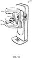
- FIG. 1B is a perspective view of the breast imaging system 100.
- the breast imaging system 100 immobilizes a patient's breast 102 for x-ray imaging (one or more of a mammography mode, a tomosynthesis mode, and a computed tomography (CT) mode) via a breast compression immobilizer unit 104 that includes a static breast support platform 106 and a moveable compression paddle 108.
- the breast support platform 106 and the compression paddle 108 each have a compression surface 110 and 112, respectively, that move towards each other to compress and immobilize the breast 102.
- the compression surface 110, 112 is exposed so as to directly contact the breast 102.
- the breast support platform 106 also houses an image receptor 116 and, optionally, a tilting mechanism 118, and optionally an anti-scatter grid.
- the immobilizer unit 104 is in a path of an imaging beam 120 emanating from x-ray source 122, such that the beam 120 impinges on the image receptor 116.
- the immobilizer unit 104 is supported on a first support arm 124 and the x-ray source 122 is supported on a second support arm 126.
- support arms 124 and 126 can rotate as a unit about an axis 128 between different imaging orientations such as cranial-caudal (CC) and mediolateral oblique (MLO) views, so that the breast imaging system 100 can take a mammogram projection image at each orientation.
- the image receptor 116 remains in place relative to the breast support platform 106 while an image is taken.
- the immobilizer unit 104 releases the breast 102 for movement of arms 124, 126 to a different imaging orientation.
- the support arm 124 stays in place, with the breast 102 immobilized and remaining in place, while at least the second support arm 126 rotates the x-ray source 122 relative to the immobilizer unit 104 and the compressed breast 102 about the axis 128.
- the breast imaging system 100 takes plural tomosynthesis projection images of the breast 102 at respective angles of the beam 120 relative to the breast 102.
- the image receptor 116 may be tilted relative to the breast support platform 106 and in sync with the rotation of the second support arm 126.
- the tilting can be through the same angle as the rotation of the x-ray source 122, but may also be through a different angle selected such that the beam 120 remains substantially in the same position on the image receptor 116 for each of the plural images.
- the tilting can be about an axis 130, which can but need not be in the image plane of the image receptor 116.
- the tilting mechanism 118 that is coupled to the image receptor 116 can drive the image receptor 116 in a tilting motion.
- the breast support platform 106 can be horizontal or can be at an angle to the horizontal, e.g., at an orientation similar to that for conventional MLO imaging in mammography.
- the breast imaging system 100 can be solely a mammography system, a CT system, or a tomosynthesis system, or a "combo" system that can perform multiple forms of imaging.
- An example of such a combo system has been offered by the assignee hereof under the trade name Selenia Dimensions.
- the breast imaging system 100 images the breast 102 by emitting an x-ray beam 120 from the x-ray source 122.
- an x-ray filter may be placed between the x-ray source 122 and the breast 102 to control wavelengths present in the x-ray beam 120 in order to regulate an energy of the x-rays that pass through the breast 102.
- the x-ray beam 120 passes through the breast 102 where it is detected by the image receptor 116.
- the image receptor 116 may include a plurality of pixels that detect the intensity of the x-ray beam 120 at a plurality of locations after the x-ray beam has passed through the breast 102.
- the attenuation of the x-ray beam 120 as it passes through the breast 102 changes depending on the structures of the breast 102. Accordingly, images of the breast may be produced from the detected x-ray beam 120.
- the image receptor 116 produces imaging information in the form of electric signals, and supplies that imaging information to an image processor 132 for processing and generating x-ray images of the breast 102.
- a system control and work station unit 138 including software controls the operation of the system and interacts with the operator to receive commands and deliver information including images of the breast 102.
- the system control and work station unit 138 may also include software for controlling the operation of the x-ray source 122.
- the x-ray beam 120 may be generated through the use of the x-ray source 122 that includes an x-ray tube. As described in more detail with reference to FIG. 2 , a voltage or signal may be applied across a filament of the x-ray tube causing electrons to be emitted from the filament.
- the emitted electrons form an electron beam that accelerates towards an anode of the x-ray tube.
- the electron beam impacts the anode, which causes the emission of x-rays from the anode that form the x-ray beam 120 used for imaging.
- the area in which the electron beam impacts the anode is referred to as the focal spot.
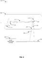
- FIG. 2 is an example system 200 for tracking a position of a focal spot of an x-ray tube.
- the system 200 may be a part of the breast imaging system 100 described with reference to FIGs. 1A and 1B .
- the system 200 may include an image capturing system comprising at least an x-ray tube 202 and a detector 204, at least one artificial target 206, and an image processing system 208.
- the x-ray tube 202 may be included as at least part of the x-ray source 122 shown and described above with reference to FIGs. 1A and 1B .
- a body of the x-ray tube 202 houses a cathode assembly including at least one filament 210 and a focusing cup 212.
- the filament 210 may be placed adjacent to the focusing cup 212 and between the focusing cup 212 and an anode 214.
- the filament 210 may be made from a material with a high melting point, such as tungsten.
- a voltage or signal may be applied across the filament 210 via wires connected to each end of the filament 210, indicated by the 1+ for the positive connection to the filament 210 and the 1- for the negative connection to the filament 210.
- a current flows through the filament 210, which heats the filament 210 and causes electrons to be emitted from the filament 210. Due to a voltage difference between the cathode assembly and the anode 214, the electrons emitted from the filament 210 are accelerated towards the anode 214. The accelerated electrons form an electron beam 216 that travels along an electron beam path. The electron beam 216 impacts the anode 214, which causes the emission of x-rays 218 from the anode 214.
- the x-rays 218 exit the body of the x-ray tube 202 through a tube window 220. The x-rays 218 that exit through the window 220 form the x-ray beam that is used for imaging, such as x-ray beam 120 discussed above with reference to FIGS. 1A-1B .
- the area in which the electron beam 216 impacts the anode 214 is referred to as the focal spot 222.
- the size of the focal spot 222 relates to the resolution desired for the imaging process. For instance, a small focal spot 222 may be used where high resolution of a small area is desired.
- the position of the focal spot 222 on the anode 214, as well as the angle of the anode 214, also has an effect on the direction of the x-rays 218 produced from the anode 214.
- the size and position of the focal spot 222 may be controlled or modified by the focusing cup 212.
- the focusing cup 212 may include a negative charge that repels the electrons emitted from the filament 210. That charge, the distribution of that charge, and the shape of the focusing cup 212 may be selected or configured to direct the electrons emitted from the filament 210 to the focal spot 222 on the anode 214.
- the artificial target 206 may be composed of a material that highly attenuates x-rays, such as metal.
- metal such as titanium.
- the artificial target may be a flexible strand or rod (e.g., a wire) of varying diameters.
- the artificial target 206 may be arranged substantially parallel to an x-axis of the detector 204 and at least a portion of the artificial target 206 may be within a projection path of an x-ray beam formed from the x-rays 218.
- the artificial target 206 may be arranged substantially parallel to a y-axis of the detector 204 and at least a portion of the artificial target 206 may be within a projection path of an x-ray beam formed from the x-rays 218.
- the system 200 may include at least two artificial targets, as shown and described in FIG. 3 .
- the artificial target 206 may be a mesh object that is arranged to extend across an entirety of the window 220 of the x-ray tube 202, as shown and described with reference to FIG. 8 .
- the artificial target 206 may be attached to the exterior of the body of the x-ray tube 202 or otherwise fastened to another component of the imaging system such that the artificial target 206 remains substantially stationary throughout the imaging process.
- the artificial target 206 may be removable (e.g., detachable) from the body of the x-ray tube 202 and/or attached in a manner that the artificial target 206 may be moved in and out of the projection path of an x-ray beam.
- the detector 204 may be included as at least part of the image receptor 116 shown and described above with reference to FIGs.1A and 1B .
- the detector 204 may detect an x-ray beam formed from the x-rays 218 after the x-ray beam passes through at least a portion of the artificial target 206.
- the detector 204 may convert the attenuated x-ray beam into an electrical signal that is then converted to an image by the image processing system 208.
- the detector 204 may be a flat-panel digital x-ray detector that includes a plurality of pixels. Each pixel may capture a portion of the x-ray beam. The captured x-rays for each pixel may then be converted into an image having corresponding pixels.
- the image can include at least the portion of the artificial target 206 as the artificial target is located within the x-ray beam and positioned between the x-ray tube 202 and the detector 204.
- the image processing system may include at least the image processor 132 shown and described above with reference to FIGs. 1A and 1B .
- a position of the focal spot 222 may change.
- a projection path for the x-ray beam may correspondingly change causing any objects, such as the artificial target 206, in the respective projection paths to be different (e.g., spatially shifted) among the image captures.
- the artificial target 206 is a substantially stationary target, a first position of the artificial target 206 in an initial image may be different than a second position of the artificial target 206 in a subsequent image.
- the image processing system 208 may identify the shift of the artificial target 206 from the first position to the second position, where the shift corresponds to the change in the position of the focal spot 222 from the capture of the initial image to the capture of the subsequent image.
- a current image e.g., the subsequent image
- the subsequent image may be adjusted according to a same magnitude but opposite direction of the identified shift.
- the system 200 may also include an apparatus that is capable of controlling dimensions of an electron beam received at the anode 214, where the dimensions of the electron beam affect the position of the focal spot 222 on the anode 214. Therefore, a control signal may be generated that causes the apparatus to adjust the dimensions of the electron beam to reverse the change in the position of the focal spot 222 for subsequent imaging. Example apparatuses are described in detail below with reference to FIGs. 10-12 .
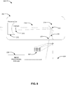
- FIG. 3 is a view of an example arrangement of at least two artificial targets 302, 304 in a system for tracking a position of a focal spot of an x-ray tube 202.
- the system may be similar to the system 200, shown and described above with reference to FIG. 2 , with the exception that the system includes two artificial targets 302, 304.
- the view is from the perspective of a detector, such as the detector 204 shown and described with reference to FIG. 2 , looking up towards the body of the x-ray tube 202.
- the first artificial target 302 and the second artificial target 304 may be arranged relative to the tube window 220 of the x-ray tube 202 and the detector.
- the first artificial target 302 and the second artificial target 304 may be arranged such that the x-rays 218 exiting the body of the x-ray tube 202 through the tube window 220 form an x-ray beam that passes through at least a portion of the artificial targets 302, 304 for detection by the detector.
- the artificial targets 302, 304 may be arranged such that at least a portion of each of the artificial targets 302, 304 is within a projection path of the x-ray beam.
- the detector may convert the attenuated x-ray beam into an electrical signal that is then converted to an image by an image processing system, such as the image processing system 208 shown and described with reference to FIG. 2 .
- the image may include the portions of first artificial target 302 and the second artificial target 304 that are within the x-ray beam path.
- the first artificial target 302 may be arranged in a first direction and the second artificial target 304 may be arranged in a second direction.
- the first direction may be substantially parallel to an x-axis of the detector and the second direction may be parallel to a y-axis of the detector.
- a position of the focal spot of the anode may change each time a new electron beam impacts the anode (e.g., each time a new image is to be captured).
- a projection path for an x-ray beam formed by the x-rays 218 emitted from the anode may correspondingly change causing any objects, such as the first artificial target 302 and the second artificial target 304, in the respective projection path to be different (e.g., spatially shifted) among the image captures.
- a position of the first artificial target 302 and the second artificial target 304 in an initial image may be different than a position of the first artificial target 302 and the second artificial target 304 in a subsequent image.
- the image processing system may identify a shift of the first artificial target 302 from a first position in the initial image to a second position in the subsequent image.
- the shift may correspond to a change in the position of the focal spot in the second direction.
- the image processing system may identify the shift along a second direction that is substantially parallel to the y-axis of the detectors and thus, the change in the position of the focal spot along the y-axis.
- the image processing system may identify a shift of the second artificial target 304 from a first position in the initial image to a second position in the subsequent image.
- the shift may correspond to a change in the position of the focal spot in the first direction.
- the image processing system may identify the shift along a first direction that is substantially parallel to the x-axis of the detector and thus, the change in the position of the focal spot along the x-axis.
- FIG. 4A illustrates an example representation of a normalized subsequent image 400 when a focal spot position has changed.
- FIG. 4B depicts the normalized subsequent image 400 from which the representation in FIG. 4A is based.
- the image 400 may be generated by a system that is similar to the system 200 shown and described with reference to FIG. 2 , with the exception that it includes at least a first artificial target 302 and a second artificial target 304 as shown and described with reference to FIG. 3 .
- the image processing system may receive an initial image from the image capturing system for use in gain map generation, as described further below.
- the initial image may be an Automatic Exposure Control (AEC) Scout image.
- the initial image may include the first artificial target 302 and the second artificial target 304 at respective positions in the initial image.
- AEC Automatic Exposure Control
- initial image data that is received from the detector of the image capturing system may be in a raw format, such as pixels.
- the detector may include a plurality of pixels, and there may be inherent differences (e.g., different amplification gains and offsets) in the response of different pixels to the x-ray beam detected at the detector.
- incident x-ray intensity across the detector surface may be nonuniform due to the "heel effect", for example, leading to further variances between pixel values that the pixels provide.
- gain calibration and image correction techniques may be employed.
- a gain map may be generated on a pixel-by-pixel basis to equalize or correct for the variances in pixel values recorded in the initial image data. For example, in an initial captured image, a median pixel intensity value for all the pixels of the detector may be determined. For each individual pixel, a ratio of the median intensity value to a value of the respective pixel may yield a coefficient that is applied to the respective pixel to correct the respective pixel (e.g., to equalize the intensity value of the pixel each of the other pixels). The collection of those coefficients for each pixel may be referred to as a gain map.
- a gain map may be generated for each type of exposure mode (e.g., for each type of filter applied for CEDM as discussed further with reference to FIGs.
- a new gain map may be generated at predetermined time intervals.
- the gain map may be generated using techniques described in commonly assigned U.S. Pat. No. 7,991,106 , which is hereby incorporated by reference in its entirety. These techniques are provided merely as examples, and those having skill in the art will recognize and understand additional or different techniques for generating a gain map.
- the artificial targets 302, 304 block the x-rays attempting to pass therethrough and prevent these x-rays from reaching the detector. Accordingly, in the initial image data that is received from the detector, the pixels corresponding to the respective positions of the artificial targets 302, 304 in the initial image may appear white due to lower pixel intensity values than the surrounding imaged environment resulting from the artificial targets 302, 304 blocking the x-rays from reaching the detector. Accordingly, when generating a gain map based on the initial image, the pixel intensity values corresponding to the respective positions of the artificial targets 302, 304 in the initial image will be lower than the median pixel intensity value for all the pixels.
- the coefficients in the gain map for the pixels corresponding to the respective positions of the first artificial target 302 and the second artificial target 304 in the initial image will be a value greater than one to increase intensity (e.g., to equalize intensity with other pixels), or another type of value that compensates for the presence of the first artificial target 302 and the second artificial target 304.
- the gain map may be stored in memory of the image processing system and applied to subsequent images that are received to normalize the subsequent images. Normalization may involve correction of pixel values according to the gain map to bring the pixel values in the subsequent image closer to the pixel values that would have been produced if all the pixels had the same response to uniform exposure to the x-ray beam. Additionally, the coefficients in the gain map for the pixels corresponding to the respective positions of the artificial targets 302, 304 in the initial image may serve as references for an initial position of the focal spot during the capture of the initial image, and thus application of the gain map can identify whether the focal spot position has changed or not.
- a subsequent image including the artificial targets 302, 304 may be received. Similar to the initial image, the artificial targets 302, 304 in the subsequent image may appear white due to lower pixel intensity values associated with the artificial targets 302, 304 than the surrounding imaged environment.
- the gain map generated from the initial image can then be applied to correct for these lower pixel intensity values such that the pixel intensity values will be equal across all pixels (e.g., equal one) forming a blank, uniform image as the normalized subsequent image.
- this equalization is dependent on the respective positions of the artificial targets 302, 304 in the initial image from which the gain map was generated not changing in the subsequent image such that the coefficients of the gain map, when applied, may align with the corresponding pixels to create the blank, uniform image.
- the projection paths for the x-ray beams may be maintained such that the artificial targets 302, 304 remain in a same respective position in the subsequent image as the initial image.
- the application of the gain map causes the proper coefficients to be applied to the pixels corresponding the artificial targets 302, 304 in the subsequent image.
- the pixel intensity values will be equal across all pixels (e.g., equal one) forming the blank, uniform image as the normalized subsequent image. In other words, the artificial targets 302, 304 will not be visible in the normalized subsequent image.
- the projection paths for the x-ray beams may be different causing the artificial targets 302, 304 to be in different positions in the subsequent image.
- the coefficients for the pixels corresponding to the respective positions of the artificial targets 302, 304 in the initial image do not align with the pixels corresponding to the position of the artificial targets 302, 304 in the subsequent image, which prevents the blank, uniform image from forming. Rather the coefficients are applied to pixels in the subsequent image that are of a higher pixel intensity value (e.g., applied to pixels corresponding to areas where x-rays were not blocked from reaching detector).
- phantom targets that appear overcompensated are visible in the normalized subsequent image.
- the phantom targets are present at the first position of the artificial targets 302, 304 in the initial image from which the gain map was generated.
- the artificial targets 302, 304 maintain their white appearance in the normalized subsequent image and are present at the second position of the artificial targets 302, 304 in the subsequent image.
- two sets of the artificial targets 302, 304 are visible in the normalized subsequent image, one set corresponding to the position of the artificial targets 302, 304 in the initial image and the other set corresponding to the position of the artificial targets 302, 304 in the subsequent image.
- the image 400 is an example of the normalized subsequent image when the focal spot position has changed.
- the image 400 shows a first position 402 of the first artificial target 302 and a first position 404 of the second artificial target 304 in the initial image from which the gain map was generated (e.g. the phantom targets), as well as a second position 406 of the first artificial target 302 and a second position 408 of the second artificial target 304 in the subsequent image.
- the image processing system may identify a shift of the first artificial target 302 from the first position 402 to the second position 406, where the shift corresponds to a change in the position of the focal spot from the capture of the initial image to the capture of the subsequent image.
- the shift identified is along the y-axis, and thus the shift corresponds to a focal spot position change along the y-axis.
- a profile plot is generated, as shown and described with reference to FIG. 6 .
- the image processing system may identify a shift of the second artificial target 304 from the first position 404 to the second position 408, where the shift corresponds to a change in the position of the focal spot from the capture of the initial image to the capture of the subsequent image.
- the shift identified is along the x-axis, and thus the shift corresponds to a focal spot position change along the x-axis.
- a profile plot is generated, as shown and described with reference to FIG. 5 .
- the changes in focal spot position may induce artifacts that degrade a quality of the image 400.
- other factors may contribute to the induction of artifacts.
- other objects in the projection paths of the x-ray beams such as an x-ray filter, a collimator blade tip, an anti-scatter grid, or carbon fiber material of the breast support platform 106, may appear differently (e.g., spatially shift) as successive images are captured.
- the change in focal spot position may cause a defect in the x-ray filter (e.g., a wrinkle) forming an x-ray filter induced artifact, such as artifact 410.
- a position of collimator blade tip may result in a chest wall band artifact. Degradation of image quality caused by artifacts, such as the artifact 410, may reduce the diagnostic usefulness of the resultant medical images.
- the image 400 can be adjusted to account for the shift and remove the artifact 410.
- the image 400 can be adjusted according to a same magnitude but opposite direction of the shift.
- the changes in the position of the focal spot determined based on the shift can be reversed for subsequent imaging by utilizing an apparatus of the system that is capable of controlling dimensions of an electron beam received at the anode, where the dimensions of the electron beam affect the position of the focal spot.
- methods described in detail with reference to FIGs. 15 and 16 may be performed to remove the x-ray filter induced artifact 410 from the image 400.
- FIG. 5 illustrates a profile plot generated to identify a shift in position of an artificial target along an x-axis.
- Image 500 may be a portion of the image 400 shown and described with reference to FIGs. 4A and 4B (e.g., a portion of the normalized subsequent image).
- Image 500 includes the second artificial target 304 that is arranged substantially parallel to the y-axis of the detector, enabling identification of the shift in position of the second artificial target 304 along a direction that is substantially parallel to the x-axis of the detector (e.g., enable identification of a shift along the x-axis).
- a profile plot 506 may be generated along a line 502 intersecting the second artificial target 304 in a region 504 of the image 500. As illustrated, a direction of the line 502 may be along the x-axis.
- the profile plot 506 may include pixel intensity values for a predefined range of pixels in the region 504 along the direction of the line 502.
- the x-axis 508 of the profile plot 506 may include the predefined range of pixels along the x-axis (e.g., a range of x-axis pixel coordinates)
- the y-axis 510 of the profile plot 506 may include pixel intensity values corresponding to each pixel within the predefined range of pixels.
- a local maximum and a local minimum and the pixel intensity values thereof may be identified. For example, a first pixel 512 having a local maximum pixel intensity value and a second pixel 514 having a local minimum pixel intensity value may be identified.
- identifying the local maximum and the local minimum may further include determining a median pixel intensity value 518 for the predefined range of pixels, where the pixels having local maximum and minimum intensity values are greater than or less than the median pixel intensity value 518, respectively, by at least a threshold value.
- the first pixel 512 having the local maximum pixel intensity value may have a pixel intensity value greater than the median pixel intensity value 518 by at least a threshold value.
- the second pixel 514 having the local minimum pixel intensity value may have a pixel intensity value less than the median pixel intensity value 518 by at least a threshold value.
- local maxima and local minima may be identified using parsing methods, such as C++ or two-dimensional (2D) array parsing methods.
- parsing methods such as C++ or two-dimensional (2D) array parsing methods.
- a 2D region of interest (ROI) for both the artificial targets 302, 304 may be known. Because there are only the artificial targets 302, 304 in the fixed regions, the minimum and the maximum from a row or column of the fixed 2D ROI is easily identified via parsing the 2D array.
- the 2D ROI for the second artificial target 304 may be parsed to identify the first pixel 512 having the local maximum pixel intensity value and the second pixel 514 having the local minimum pixel intensity value from a row of the fixed 2D ROI.
- local maxima and local minima may be identified through data analytics algorithms.
- the findpeaks function and the islocalmin functions available in the MATLAB software product available from The MathWorks, Inc. of Natick, MA are capable of identifying local maxima and minima as well as the values for those local maxima and minima.
- the findpeaks function and the islocalmin functions may be capable of identifying local maxima and minima that satisfy threshold value requirements using prominence measurements (e.g., prominence of a peak or valley measures how much the peak or valley stands out due to its intrinsic height and its location relative to other peaks or valleys). These functions are provided merely as examples, and those having skill in the art will recognize and understand additional or different techniques for identifying maxima and minima within sets of data.
- the position of the second artificial target 304 changes from the first position 404 to the second position 408. Therefore, when the gain map generated from the initial image is applied to the subsequent image to generate the normalized subsequent image (e.g., image 500), the gain map coefficients for the pixels corresponding to the first position 404 of the second artificial target 304 in the initial image do not align with the pixels corresponding to the second position 408 of the second artificial target 304 in the subsequent image, which prevents a blank, uniform image from forming in the image 500.
- the gain map generated from the initial image is applied to the subsequent image to generate the normalized subsequent image (e.g., image 500)
- the gain map coefficients for the pixels corresponding to the first position 404 of the second artificial target 304 in the initial image do not align with the pixels corresponding to the second position 408 of the second artificial target 304 in the subsequent image, which prevents a blank, uniform image from forming in the image 500.
- the gain map coefficients for the pixels corresponding to the first position 404 of the second artificial target 304 which are values greater than one, are applied to pixels in the subsequent image that are of a higher pixel intensity value.
- a phantom target having an overcompensated appearance e.g., due to the higher intensity value comparative to the median pixel intensity value 518, is visible in the image 500 at the first position 404 of the second artificial target 304.
- the first pixel 512 having the local maximum pixel intensity value in the profile plot 506 may correspond to the first position 404.
- the second artificial target 304 maintains a white appearance (e.g., due to a lower intensity value comparative to the median pixel intensity value 518) in the image 500 at the second position 408 of the second artificial target 304. Accordingly, the second pixel 514 having the local minimum pixel intensity value in the profile plot 506 may correspond to the second position 408 of the second artificial target 304.
- a pixel distance 516 between the first pixel 512 and the second pixel 514 may be determined.
- the pixel distance 516 may represent the shift (in pixels) of the position of the second artificial target 304 along the x-axis from the initial image to the subsequent image.
- FIG. 6 illustrates a profile plot generated to identify a shift in position of an artificial target along a y-axis.
- Image 600 may be a portion of the image 400 shown and described with reference to FIGs. 4A and 4B (e.g., a portion of the normalized subsequent image).
- Image 600 includes the first artificial target 302 that is arranged substantially parallel to the x-axis of the detector, enabling identification of the shift in position of the first artificial target 302 along a direction that is substantially parallel to the y-axis of the detector (e.g., enabling identification of a shift along the y-axis).
- a profile plot 606 may be generated along a line 602 intersecting the first artificial target 302 in a region 604 of the image 600. As illustrated, a direction of the line 602 may be along the y-axis.
- the profile plot 606 may include pixel intensity values for a predefined range of pixels in the region 604 along the direction of the line 602.
- the x-axis 608 of the profile plot 606 may include the predefined range of pixels along the y-axis (e.g., a range of y-axis pixel coordinates), and the y-axis 610 of the profile plot 606 may include pixel intensity values corresponding to each pixel within the predefined range of pixels.
- a local maximum and a local minimum and the pixel intensity values thereof may be identified. For example, a first pixel 612 having a local maximum pixel intensity value and a second pixel 614 having a local minimum pixel intensity value may be identified.
- the local maxima and local minima may be identified using parsing methods.
- the 2D ROI for the first artificial target 302 may be parsed to identify the first pixel 612 having the local maximum pixel intensity value and the second pixel 614 having the local minimum pixel intensity value from a column of the fixed 2D ROI.
- the local maxima and local minima may be identified through data analytics algorithms.
- identifying the local maximum and the local minimum may further include determining a median pixel intensity value 618 for the predefined range of pixels, where the pixels having local maximum and minimum intensity values are greater than or less than the median pixel intensity value 618, respectively, by at least a threshold value.
- the gain map generated from the initial image is applied to the subsequent image to generate the normalized subsequent image (e.g., image 600)
- the gain map coefficients for the pixels corresponding to the first position 402 of the artificial target 302 in the initial image do not align with the pixels corresponding to the second position 406 of the artificial target 302 in the subsequent image, which prevents a blank, uniform image from forming in the image 600.
- the gain map coefficients for the pixels corresponding to the first position 402 of the artificial target 302 in the initial image which are values greater than one, are applied to pixels in the subsequent image that are already of a higher pixel intensity value.
- a phantom target having an overcompensated appearance e.g., due to the higher intensity value comparative to the median pixel intensity value 618, is visible in the image 600 at the first position 402 of the artificial target 302.
- the first pixel 612 having the local maximum pixel intensity value in the profile plot 606 may correspond to the first position 402.
- the artificial target 302 maintains a white appearance (e.g., due to a lower intensity value comparative to the median pixel intensity value 618) in the image 600 at the second position 406 of the artificial targets 302. Accordingly, the second pixel 614 having the local minimum pixel intensity value in the profile plot 606 may correspond to the second position 406 of the first artificial target 302.
- a pixel distance 616 between the first pixel 612 and the second pixel 614 may be determined.
- the pixel distance 616 may represent the shift (in pixels) of the position of the first artificial target 302 from the initial image to the subsequent image along the y-axis.
- an entirety of the image 400 may be adjusted based on the pixel distance 516 and the pixel distance 616 to correct for the shift along the x-axis and the y-axis, respectively.
- the image may be corrected in the x- and y-axes according to a same magnitude but opposite direction of the identified shifts.
- the image 400 may be shifted 21 pixels in a positive direction along the x-axis and 22 pixels in the positive direction along the y-axis.
- the gain map generated based on the initial image may be adjusted based on the pixel distance 516 and the pixel distance 616, and reapplied to the subsequent image to generate a new normalized subsequent image.
- the pixel distance 516 may correspond to a change in position of the focal spot along the x-axis and the pixel distance 616 may correspond to a change in position of the focal spot along the y-axis.
- the pixel distance 516 may be converted to a first focal spot shift vector representing the change in the position of the focal spot along the x-axis
- the pixel distance 616 may be converted to a second focal spot shift vector representing the change in the position of the focal spot along the y-axis, as described in greater detail with reference to FIG. 7 below.
- a control signal may then be generated based on the first and second focal spot shift vectors for transmission to an apparatus of the system that is capable of controlling dimensions of an electron beam received at the anode of the x-ray tube.
- dimensions of the electron beam may affect the position of the focal spot on the anode, and thus the control signal may cause the apparatus to adjust the dimensions of the electron beam to reverse the change in the position of the focal spot along the x-axis and y-axis for subsequent imaging.
- FIG. 7 illustrates example focal spot shift vectors.
- a pixel distance representing the shift of the second artificial target along the x-axis may be determined as described with reference to FIG. 5 .
- the pixel distance may correspond to a change in position of the focal spot along the x-axis.
- the pixel distance may be a magnitude of a first focal spot shift vector (H) 702.
- the first focal spot shift vector (H) 702 may have one of a positive or a negative direction along the x-axis. As illustrated in FIG. 7 , the first focal spot shift vector (H) 702 may have a negative direction along the x-axis.
- the positive or negative direction may be based on a position of the first pixel where the local maximum occurs (e.g., a peak) relative to the second pixel where the local minimum occurs (a valley). For example, if the first pixel has a higher x-axis coordinate value than the second pixel causing the valley to occur to the left of the peak, such as first pixel 512 and second pixel 514 in FIG. 5 , the first focal spot shift vector (H) 702 may have a negative direction along the x-axis. Alternatively, if the first pixel has a lower x-axis coordinate value than the second pixel causing the peak to occur to the left of the valley, the first focal spot shift vector (H) 702 may have a positive direction along the x-axis.
- a pixel distance representing the shift of the first artificial target along the y-axis may be determined as described with reference to FIG. 6 .
- the pixel distance may correspond to a change in position of the focal spot along the y-axis.
- the pixel distance may be a magnitude of a second focal spot shift vector (V) 704.
- the second focal spot shift vector (V) 704 may have one of a positive or a negative direction along the y-axis. As illustrated in FIG. 7 , the second focal spot shift vector (V) 704 may have a negative direction along the y-axis.
- the positive or negative direction may be based on a position of the first pixel where the local maximum occurs (e.g., a peak) relative to the second pixel where the local minimum occurs (a valley).
- the second focal spot shift vector (V) 704 may have a negative direction along the y-axis.
- the first focal spot shift vector (H) 702 may have a positive direction along the y-axis.
- a resultant focal spot shift vector (S) 706 may be determined based on the first focal spot shift vector (H) 702 and the second focal spot shift vector (V) 704.
- the resultant focal spot shift vector 706 (S) may be converted from pixels to another distance unit (e.g., micrometers) at the focal spot using a multiplier. For example, each pixel has a defined width and length that may be measured in micrometers.
- a first angle ( ⁇ 1 ) 708 associated with the resultant focal spot shift vector (S) 706 may be determined based on the first focal spot shift vector (H) 702 and the second focal spot shift vector (V) 704.
- H is 21 pixels and V is 22 pixels
- a control signal may then be generated based on the first angle ( ⁇ 1 ) 708 for transmission to an apparatus of the system, shown and described with reference to FIGs. 10-12 , that is capable of controlling dimensions of an electron beam received at the anode of the x-ray tube.
- the dimensions of the electron beam affect the position of the focal spot on the anode, and therefore, the control signal may cause the apparatus to adjust the dimensions of the electron beam to reverse the change in the position of the focal spot along the x-axis and the y-axis.
- a second angle ( ⁇ 2 ) 710 congruent to the first angle ( ⁇ 1 ) 708 may be identified.
- the second angle ( ⁇ 2 ) 710 may have a same measure in degrees (e.g., 46.33°) but is in an opposite direction to enable reversal of the change of the position of the focal spot.
- the control signal may cause the apparatus to adjust the dimensions of the electron beam by the magnitude and direction of the second angle ( ⁇ 2 ) 710.
- FIG. 8 is an example system 800 having a mesh object artificial target 802 for tracking a position of a focal spot 222 of an x-ray tube 202.
- the system 800 may be utilized for calibration, as discussed in greater detail below.
- the system 800 is similar to the system 200 shown and described with reference to FIG. 2 , with the exception of a type of artificial target implemented by the system 800.
- the artificial target in system 800 may be a mesh object artificial target 802.
- the mesh object artificial target 802 may be arranged relative to the tube window 220 and the detector 204 to extend along an x-axis and a y-axis across an entirety of the tube window 220.
- the mesh object artificial target 802 may be formed from connected strands of metal (e.g., wires) or other material that highly attenuates x-rays.
- the strands can be connected to form a grid pattern.
- a first set of strands may be arranged substantially parallel to the y-axis of the detector 204 and extend across an entirety of the tube window 220, while a second set of strands may be arranged substantially parallel to the x-axis of the detector 204 and extend across an entirety of the tube window 220.
- the mesh object artificial target 802 or at least a portion of the strands thereof may be attached to the body of the x-ray tube 202 or otherwise positioned such that the mesh object artificial target 802 remains stationary throughout the imaging process.
- the mesh object artificial target 802 may be removable (e.g., detachable) from the body of the x-ray tube 202 and/or attached in a manner that the mesh object artificial target 802 may be moved in and out of the projection path of an x-ray beam.
- a position of the focal spot 222 may change.
- a projection path for the x-ray beam may correspondingly change causing any objects, such as the mesh object artificial target 802, in the respective projection paths to be different (e.g., spatially shifted) among the image captures.
- a first position of the mesh object artificial target 802 in an initial image may be different than a second position of the mesh object artificial target 802 in a subsequent image due to the focal spot shift.
- the image processing system 208 may identify the shift of the mesh object artificial target 802 from the first position to the second position, where the shift corresponds to the change in the position of the focal spot 222.
- the shift of the mesh object artificial target 802 may be identified on a per-strand basis. For example, the shift may be identified for each strand of the first set of strands in the mesh object artificial target 802 that are positioned substantially parallel to the y-axis of the detector 204. Additionally, the shift may be identified for each strand of the second set of strands in the mesh object artificial target 802 that are positioned substantially parallel to the x-axis of the detector 204. In some examples, shifts may be identified throughout the entirety of the image, however the value or rate of the shifts identified for the respective strands may be different based on the x-axis or y-axis position of the strands relative to an apex of the focal spot.
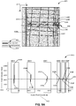
- FIG. 9A illustrates an example representation of a normalized subsequent image 900 when a focal spot position has changed, and a corresponding profile plot 910 generated to identify a shift in position of a mesh object artificial target along an x-axis.
- FIG. 9B depicts the normalized subsequent image 900 from which the representation in FIG. 9A is based.
- the image 900 may be generated by the system 800 having a mesh object artificial target 802 as shown and described with reference to FIG. 8 .
- the image processing system may receive an initial image from the image capturing system.
- the initial image may include the mesh object artificial target 802 at a respective position in the initial image.
- Again map may be generated based on the initial image, and applied to a subsequently received image that includes the mesh object artificial target 802 to generate a normalized subsequent image.
- the gain map may be generated and applied in a similar manner described above with reference to FIGs. 4A and 4B , where application of the gain map may identify whether the focal spot position during the capture of the initial image and the capture of the subsequent image has changed.
- the image 900 is an example of the normalized subsequent image when the focal spot position has changed.
- the projection paths for the x-ray beams may be different causing the mesh object artificial target 802 to be in different positions in the subsequent image
- the mesh object artificial target 802 is at a first position in the initial image versus a second position in the subsequent image.
- two sets of the mesh object artificial target 802 are visualized in the normalized subsequent image, where one set is at the first position and the other set is at the second position for reasons further detailed with reference to FIGs. 4A and 4B .
- the image 900 shows a first position 902 of the mesh object artificial target 802 in the initial image from which the gain map was generated (e.g., the phantom targets), as well as a second position 904 of the mesh object artificial target 802 in the subsequent image.
- the mesh object artificial target 802 would not be visible in the normalized subsequent image resulting in a blank, uniform image for reasons further detailed with reference to FIGs. 4A and 4B .
- the image processing system may identify a shift of the mesh object artificial target 802 from the first position 902 to the second position 904 along a direction substantially parallel to the x-axis of the detector (e.g., along the x-axis).
- the shift corresponds to a change in the position of the focal spot along the x-axis from the capture of the initial image to the capture of the subsequent image.
- the shift may be identified on a per-strand basis. For example, a shift may be identified for each strand of the first set of strands in the mesh object artificial target 802 that are positioned substantially parallel to the y-axis of the detector.
- the profile plot 910 may be generated along a line 906 intersecting each strand of the first set of strands in respective regions 908A, 908B, 908C, 908D, 908E, and 908F, collectively regions 908, of the image 900. As illustrated, a direction of the line 906 may be along the x-axis.
- the profile plot 910 may include pixel intensity values for a predefined range of pixels in each of the regions 908 along the direction of the line 906.
- the x-axis 912 of the profile plot 910 may include the predefined range of pixels along the x-axis
- the y-axis 914 of the profile plot 910 may include pixel intensity values corresponding to each pixel within the predefined range of pixels.
- a first pixel 916 having a local maximum pixel intensity value and a second pixel 918 having a local minimum pixel intensity value may be identified.
- first pixels 916A, 916B, 916C, 916D, 916E, and 916F may correspond to a local maximum pixel intensity value for the respective regions 908A, 908B, 908C, 908D, 908E, and 908F.
- Second pixels 918A, 918B, 918C. 918D, 918E, and 918F may correspond to a local minimum pixel intensity value for the respective regions 908A, 908B, 908C, 908D, 908E, and 908F.
- identifying pixels having local maximum and minimum intensity values may further include determining a median pixel intensity value 920 for the predefined range of pixels, where the pixels having local maximum and minimum intensity values are greater than or less than the median pixel intensity value 920, respectively, by at least a threshold value.
- a pixel distance between the first pixel 916 and the second pixel 918 may be determined for each of the regions 908.
- the pixel distance may represent the shift (in pixels) of the particular strand of the mesh object artificial target 802 corresponding to the region 908 from the capture of the initial image to the capture of the subsequent image.
- the value or rate of the shifts identified for the respective strands e.g., a pixel distance between the first pixel 916 and the second pixel 918 for each of the regions 908 are different based on the x-axis coordinate position of the strands relative to an apex of the focal spot.
- FIG. 10A illustrates an example representation of a normalized subsequent image when a focal spot position has changed and a corresponding profile plot generated to identify a shift in position of a mesh object artificial target along a y-axis.
- FIG. 10B is an example of an actual normalized subsequent image from which the representation in FIG. 10A is based.
- the image 1000 may be generated by the system 800 having a mesh object artificial target 802 as shown and described with reference to FIG. 8 .
- the image processing system may receive an initial image from the image capturing system.
- the initial image may include the mesh object artificial target 802 at a respective position in the initial image.
- a gain map may be generated based on the initial image, and applied to a subsequently received image that includes the mesh object artificial target 802 to generate a normalized subsequent image.
- the gain map may be generated and applied in a similar manner described above with reference to FIGs. 4A and 4B , where application of the gain map may identify whether the focal spot position during the capture of the initial image and the capture of the subsequent image has changed.
- the image 1000 is an example of the normalized subsequent image when the focal spot position has changed.
- the projection paths for the x-ray beams may be different causing the mesh object artificial target 802 to be in different positions in the subsequent image.
- the mesh object artificial target 802 is at a first position in the initial image versus a second position in the subsequent image.
- two sets of the mesh object artificial target 802 are visualized in the normalized subsequent image, where one set is at the first position and the other set is at the second position for reasons further detailed with reference to FIGs. 4A and 4B .
- the image 1000 shows a first position 1002 of the mesh object artificial target 802 in the initial image from which the gain map was generated (e.g., the phantom targets), as well as a second position 1004 of the mesh object artificial target 802 in the subsequent image.
- the mesh object artificial target 802 would not be visible in the normalized subsequent image resulting in a blank, uniform image for reasons further detailed with reference to FIGs. 4A and 4B .
- the image processing system may identify a shift of the mesh object artificial target 802 from the first position 1002 to the second position 1004 along a direction substantially parallel to the y-axis of the detector (e.g., along the y-axis).
- the shift corresponds to a change in the position of the focal spot along the y-axis from the capture of the initial image to the capture of the subsequent image.
- the shift may be identified on a per-strand basis. For example, a shift may be identified for each strand of the second set of strands in the mesh object artificial target 802 that are positioned substantially parallel to the x-axis of the detector.
- the profile plot 1010 may be generated along a line 1006 intersecting each strand of the second set of strands in respective regions 1008A, 1008B, 1008C, 1008D, 1008E, 1008F, 1008G, and 1008H, collectively regions 1008, of the image 1000.
- a direction of the line 1006 may be along the y-axis.
- the profile plot 1010 may include pixel intensity values for a predefined range of pixels in each of the regions 1008 along the direction of the line 1006.
- the x-axis 1012 of the profile plot 1010 may include the predefined range of pixels along the y-axis
- the y-axis 1014 of the profile plot 1010 may include pixel intensity values corresponding to each pixel within the predefined range of pixels.
- a first pixel 1016 having a local maximum pixel intensity value and a second pixel 1018 having a local minimum pixel intensity value may be identified.
- first pixels 1016A, 1016B, 1016C, 1016D, 1016E, 1016F, 1016G, and 1016H may correspond to a local maximum pixel intensity value for the respective regions 1008A, 1008B, 1008C, 1008D, 1008E, 1008F, 1008G, and 1008H.
- Second pixels 1018A, 1018B, 1018C, 1018D, 1018E, 1018F, 1018G, and 1018H may correspond to a local minimum pixel intensity value for the respective regions 1008A, 1008B, 1008C, 1008D, 1008E, 1008F, 1008G, and 1008H.
- identifying pixels having local maximum and minimum intensity values may further include determining a median pixel intensity value 1020 for the predefined range of pixels, where the pixels having local maximum and minimum intensity values are greater than or less than the median pixel intensity value 1020, respectively, by at least a threshold value.
- a pixel distance between the first pixel 1016 and the second pixel 1018 may be determined for each of the regions 1008.
- the pixel distance may represent the shift (in pixels) of the particular strand of the mesh object artificial target 802 corresponding to the region 1008 from the capture of the initial image to the capture of the subsequent image.
- the value or rate of the shifts identified for the respective strands e.g., a pixel distance between the first pixel 1016 and the second pixel 1018 for each of the regions 1008 are different based on the y-axis coordinate position of the strands relative to an apex of the focal spot.
- the x-rays As the plurality of x-rays are projected within the x-ray beam from the focal spot to the detector, at least a portion of the x-rays (e.g., focal spot central rays) follow a substantially linear projection path from an apex of the focal spot to the detector. This path is illustrated by element 930 in FIGs. 9A-9B and element 1030 in FIGs. 10A-10B .
- this substantially linear path is adjacent to a chest wall of the patient whose breast is positioned in a breast imaging system, such as the breast imaging system 100.
- a value or rate of the shifts identified for the respective strands of the mesh object artificial target 802 may be different based on the position of the strands along the x- and y-axes relative to the apex of the focal spot (e.g., relative to elements 930, 1030 representing the projection path of the focal spot central rays from the apex of the focal spot).
- the strands positioned on the right hand side of the image 900 that are closest to the apex of the focal spot may experience larger shifts than the strands positioned toward the middle and left hand side of the image 900.
- values of the shifts may decrease for strands that are positioned increasingly further away from the apex of the focal (e.g., shift values decrease from regions 908F to 908A).
- the maximum shift may be associated with an x-axis pixel coordinate within the substantially linear projection path of the focal spot central rays 930.
- the maximum shift identified may be determined as the central focal spot shift along the x-axis, which represents an actual change in position of the focal spot (in pixels) along the x-axis.
- Table 1 includes example values for relative focal spot shit across the x-axis of the image 900, where each x-axis pixel coordinate corresponds to one of the regions 908A, 908B, 908C, 908D, 908E, and 908F.
- the maximum shift may be 33.58 pixels at x-axis pixel coordinate 2849 corresponding to region 908F in image 900, the region within the substantially linear projection path of the focal spot central rays 930.
- the strands positioned in the middle of the image 1000 that are closest to the apex of the focal spot may experience larger shifts than those strands positioned further away in the top and the bottom of the image 1000.
- values of the shifts may decrease for strands that are positioned increasingly further away from the apex of the focal spot (e.g., shift values decrease from regions 1008E to 1008A and from regions 1008E to 1008H).
- the maximum shift may be associated with a y-axis pixel coordinate within the substantially linear projection path of the focal spot central rays 1030.
- the maximum shift identified may be determined as the central focal spot shift along the y-axis, which represents an actual change in position of the focal spot (in pixels) along the y-axis.
- Table 2 includes example pixel values for relative focal spot shit across the y-axis of the image 1000, where each y-axis pixel coordinate corresponds to one of the regions 1008A, 1008B, 1008C, 1008D, 1008E, 1008F, 1008G and 1008H.
- the maximum shift may be 20.6 pixels at y-axis pixel coordinate 1421 corresponding to region 1008E in image 1000, the region within the substantially linear projection path of the focal spot central rays 1030.
- the central focal spot shift along the x- and y-axes represents the actual change of position in the focal spot along the x- and y-axes.
- targets such as the mesh object artificial target 802 and/or any other target positioned within the substantially linear projection path of the focal spot central rays 930, 1030 cannot be used while imaging the breast because the targets will obstruct a view of the breast.
- artificial targets such as the artificial targets 302, 304 are positioned at a back of the field of view (e.g., furthest away from the chest wall) so that the artificial targets 302, 304 do not overlap with any portion of the imaged breast.
- the second artificial target 304 may be positioned near x-axis pixel coordinate 288 corresponding to region 908A, and the first artificial target 302 may be positioned near y-axis pixel coordinate 98 corresponding to region 1008A. Accordingly, when identifying the shift of the artificial targets 302, 304 in captured images of the breast, the position of the artificial targets 302, 304 must be taken into account as the shift identified will be less than the actual change of position in the focal spot due to the highly angled projection path of the x-rays at the back of the field of view relative to the substantially linear projection path of the focal spot central rays 930, 1030 near the chest wall.
- the system 800 having the mesh object artificial target 802 may be implemented prior to imaging the patient's breast for calibration purposes. For example, prior to positioning and imaging the breast, images, such as images 900,1000, may be captured that include the mesh object artificial target 802. From these images 900, 1000, shifts across the x- and y-axes are identified, and values such as those shown in Table 1 and Table 2 are obtained.
- a ratio of the central focal spot shift to the relative spot shift at the back of the field of view where the artificial targets 302, 304 are to be positioned when imaging the patient's breast can be determined.
- This ratio is also referred to herein as the central focal spot to target ratio.
- the central focal spot to target ratio can then be applied to the shift of the artificial targets 302, 304 identified in subsequent captured images of the breast. For example, referring back to Table 1, if the relative spot shift at the central focal spot is 33.58 pixels and the relative spot shift at the x-axis pixel coordinate 288 where the second artificial target 304 is to be positioned in subsequent images is 9.4 pixels, then the central focal spot to target ratio is 33.58:9.4, which is approximately 3.57.
- the central focal spot to target ratio is 20.6:9.3, which is approximately 2.2.
- similar ratios may be obtained between the relative spot shift at the central focal spot and the relative spot shift at each of the x-axis pixel coordinates and the y-axis pixel coordinates obtained (e.g., for each of coordinates in Table 1 and Table 2). Therefore, when adjusting an image to correct for the shift created by the change in focal spot position, each portion of the image may be adjusted appropriately, as described in greater detail below.
- the mesh object artificial target 802 may then be replaced with the artificial targets 302, 304 so as not to obstruct the imaging of the breast.
- the artificial targets 302, 304 are positioned at a back of the field of view (e.g., furthest away from the chest wall) so that the artificial targets 302, 304 do not overlap with any portion of the imaged breast.
- the breast may then be positioned in the imaging field and at least a pair of images (e.g., an initial image and a subsequent image) of the breast may be captured with the artificial targets 302, 304 present. Shifts of each of the artificial targets 302, 304 from a first position to a second position between the initial image and subsequent image may be identified as described in detail with reference to FIGs.
- the identified shift for the first artificial target 302 may then be multiplied by the central focal spot to target ratio determined during the calibration (e.g., by approximately 2.2) to reflect the actual change in focal spot position along the y-axis.
- the identified shift for the second artificial target 304 may then be multiplied by the central focal spot to target ratio determined during the calibration (e.g., by approximately 3.57) to reflect the actual change in focal spot position along the x-axis.
- the subsequent image of the breast may then be adjusted based on the identified change in focal spot position along the x- and y-axes and/or the change in the position of the focal spot may be physically reversed (e.g., using electrodes or magnets positioned relative the x-ray tube) for subsequent imaging.
- each region of the image may be adjusted independently to account for the differences in shift across the image. For example, using the ratios obtained between the relative spot shift at the central focal spot and the relative spot shift at each of the x-axis pixel coordinates and the y-axis pixel coordinates obtained (e.g., for each of coordinates in Table 1 and Table 2), appropriate shift values for each region of the image can be calculated. The pixels of the image in each region may then be shifted according to a same magnitude as the calculated shift value for the region but in an opposite direction.
- the identified shift of the second artificial target 304 along the x-axis is 10 pixels and the second artificial target was placed at x-axis coordinate 288, then using the central focal spot to target ratio obtained from Table 1, it can be determined that the maximum shift at x-axis coordinate 2849 was 35.7 pixels (e.g., ratio of 3.57 multiplied by the shift of 10 pixels). The shift can then be identified at each of the other x-coordinates corresponding to the respective regions of the image based on ratios obtained.
- the ratio of the relative shift of central focal spot to the relative shift of at the x-axis coordinate 1095 is 1.89 (e.g., 33.58:17.77). Therefore, when it is determined that the maximum shift at x-coordinate 2849 is 35.7 pixels, the shift for the region in the image corresponding to the x-coordinate 1095 is 18.8 (e.g., 35.7/1.89).
- the maximum shift along the x- and y-axes representing the actual change in position of the focal spot may be the pixel distance values converted to the focal spot shift vectors. Therefore, the pixel distance shift identified for the first artificial target 302 along the y-axis and the pixel distance shift identified for the second artificial target 304 along the x-axis are multiplied by the respective central focal spot to target ratios to obtain the maximum shift along the x- and y-axes. Using a similar method described above with reference to FIG. 7 , the pixel distances associated with the maximum shift may be converted to focal spot shift vectors representing the change in the position of the focal spot along the x- and y-axes.
- a control signal may then be generated based on the focal spot shift vectors for transmission to an apparatus of the system that is capable of controlling dimensions of an electron beam received at the anode of the x-ray tube.
- dimensions of the electron beam may affect the position of the focal spot on the anode, and thus the control signal may cause the apparatus to adjust the dimensions of the electron beam to reverse the change in the position of the focal spot along the x- and y- axes for subsequent imaging.
- FIG. 11 is an example system 1100 having an apparatus comprised of magnets 1102, 1104 that is capable of controlling dimensions of an electron beam 216.
- the system 1100 is similar to the system 200 shown and described with reference to FIG. 2 , with the exception that the system 1100 includes the apparatus comprised of magnets 1102, 1104, and at least a first artificial target 302 and a second artificial target 304 as shown and described with reference to FIG. 3 .
- the system 1100 may include only one artificial target, such as the artificial target 206, as shown and described with reference to FIG. 2 .
- the system 1100 may include a mesh object artificial target, similar to the mesh object artificial target 802 shown and described with reference to FIG. 8 .
- the apparatus may be a component housed within the x-ray tube 202. In other examples, and as illustrated in FIG. 11 , the apparatus may be arranged exterior to the x-ray tube 202.
- the apparatus can include at least two magnets: a first magnet 1102 and a second magnet 1104.
- the magnets 1102, 1104 may be electromagnets that are capable of being controlled electronically. For example, providing a signal to the magnets 1102, 1104 may vary the strength of the magnetic field of the magnets 1102, 1104.
- the first magnet 1102 may be configured to deflect the electron beam 216 in one direction.
- the second magnet 1104 may be configured to deflect the electron beam 216 in an opposite direction.
- a projection path for an x-ray beam formed by the x-rays emitted from the anode 214 may correspondingly change causing any objects, such as the first artificial target 302 and the second artificial target 304, in the respective projection path to be different (e.g., spatially shifted) among the image captures.
- a position of the first artificial target 302 and the second artificial target 304 in an initial image can be different than a position of the first artificial target 302 and the second artificial target 304 in a subsequent image even though the first artificial target 302 and the second artificial target 304 are stationary targets.
- the image processing system 208 can identify a shift of the first artificial target 302 and the second artificial target 304 from a first position in the initial image to a second position in the subsequent image, where the shift corresponds to a change in the position of the focal spot 222.
- the first artificial target 302 may be arranged substantially parallel to the x-axis of the detector 204
- the second artificial target 304 may be arranged substantially parallel to the y-axis of the detector 204. Therefore, the image processing system 208 may identify the shift along both x- and y-axes and thus, the change in the position of the focal spot 222 along the x- and y-axes.
- the shift of the first artificial target 302 and the second artificial target 304 from the first position in the initial image to the second position in the subsequent image may be identified in one or more directions (e.g., along x- and y-axes) by generating profile plots.
- pixel distances representing the identified shift of the artificial targets 302, 304 along the x- and/or y-axes may be converted to first and second focal spot shift vectors, respectively.
- a resultant focal spot shift vector and a first angle associated with the resultant focal spot shift vector may then be determined based on the first and second focal spot shift vectors.
- a control signal may then be generated based on the first angle associated with the resultant focal spot shift vector that may cause the apparatus of the system 1100 to adjust the dimensions of the electron beam 216.
- the control signal may identify a second angle that is congruent to the first angle associated with the resultant focal spot shift vector (e.g., has a same measure in degrees or magnitude) but is in an opposite direction to enable reversal of the change of the position of the focal spot 222.
- the control signal may cause the apparatus of the system 1100 to adjust the dimensions of the electron beam 216 by the magnitude and direction of the second angle to reverse the change in the position of the focal spot 222 for subsequent (e.g., future) imaging.
- the control signal may cause the first magnet 1102 to deflect the electron beam 216 in the one direction based on a strength of the first magnet 1102 as a function of the identified shift. Additionally or alternatively, based on the direction of the second angle, the control signal may cause the second magnet 1104 to deflect the electron beam 216 in the opposite direction based on a strength of the second magnet 1104 as a function of the identified shift.
- At least one of the first magnet 1102 and the second magnet 1104 may be positioned parallel to the first focal spot shift vector, while the other of the first magnet 1102 and the second magnet 1104 may be positioned parallel to the second focal spot shift vector.
- the first magnet 1102 and the second magnet 1104 may be positioned 90 degrees from another, and may work individually or in conjunction with one another based on the direction of the second angle to deflect the electron beam 216 along the x- and/or y-axes.
- the first magnet 1102 and the second magnet 1104 may be arranged in a different manner (e.g., diagonally).
- the apparatus may include a single magnet that is able to deflect electron beam 216 in one direction.
- FIG. 12 is another example system 1200 having an apparatus comprised of electrodes that is capable of controlling dimensions of an electron beam.
- the system 1200 is similar to the system 200 shown and described with reference to FIG. 2 , with the exception that the system 1200 includes the apparatus comprised of electrodes, and at least a first artificial target 302 and a second artificial target 304 as shown and described with reference to FIG. 3 .
- the system 1200 may include only one artificial target, such as the artificial target 206, as shown and described with reference to FIG. 2 .
- the system 1200 may include a mesh object artificial target, similar to the mesh object artificial target 802 shown and described with reference to FIG. 8 .
- the apparatus may be a component housed within the x-ray tube 202, as illustrated. In other examples, the apparatus may be arranged exterior to the x-ray tube 202.
- the apparatus can include a set of electrodes: a first electrode 1202 and a second electrode 1204.
- a control signal may be applied across wires or terminals connected to the electrodes 1202, 1204 as depicted by the Control+ and Control- in FIG. 11 .
- the first electrode 1202 may be positioned opposite a path of the electron beam 216 from the second electrode 1204.
- the control signal When the control signal is applied across the first electrode 1202 and the second electrode 1204, an electric field is generated between them. The electric field interacts with the electrons in the electron beam 216 due to the negative charge of the electrons in the electron beam 216.
- the electrons in the electron beam 216 may either be drawn towards the first electrode 1202 (e.g., electrons may be deflected in one direction) or drawn towards the second electrode 1204 (e.g., electrons may be deflected in an opposite direction).
- the position that the electron beam 216 impacts the anode 214 may be altered.
- the position of the focal spot 222 may be altered.
- a position of the focal spot 222 of the anode 214 can change.
- a projection path for an x-ray beam formed by the x-rays emitted from the anode 214 may correspondingly change causing any objects, such as the first artificial target 302 and the second artificial target 304, in the respective projection path to be different (e.g., spatially shifted) among the image captures.
- a position of the first artificial target 302 and the second artificial target 304 in an initial image may be different than a position of the first artificial target 302 and the second artificial target 304 in a subsequent image.
- the image processing system 208 may identify a shift of the first artificial target 302 and the second artificial target 304 from a first position in the initial image to a second position in the subsequent image, where the shift corresponds to a change in the position of the focal spot 222.
- the first artificial target 302 may be arranged substantially parallel to the x-axis of the detector 204
- the second artificial target 304 may be arranged substantially parallel to the y-axis of the detector 204. Therefore, the image processing system 208 may identify the shift along both x- and y-axes and thus, the change in the position of the focal spot 222 along the x- and y-axes.
- the shift of the first artificial target 302 and the second artificial target 304 from the first position in the initial image to the second position in the subsequent image may be identified in one or more directions (e.g., along x- and y-axes) by generating profile plots.
- pixel distances representing the identified shift of the artificial targets 302, 304 along the x- and/or y-axes may be converted to first and second focal spot shift vectors, respectively.
- a resultant focal spot shift vector and a first angle associated with the resultant focal spot shift vector may then be determined based on the first and second focal spot shift vectors.
- the control signal applied across the wires or terminals connected to the electrodes 1202, 1204 may be generated based on the first angle associated with the resultant focal spot shift vector. For example, a second angle that is congruent to the first angle associated with the resultant focal spot shift vector (e.g., has a same measure in degrees or magnitude) but is in an opposite direction may be identified to enable reversal of the change of the position of the focal spot 222 for subsequent (e.g., future) imaging.
- the control signal may cause the dimensions of the electron beam 216 to adjust by the magnitude and direction of the second angle.
- the control signal may cause the electrons in the electron beam 216 to be drawn towards the first electrode 1202 (e.g., electrons may be deflected in one direction). The electrons may be deflected in the one direction based on the strength of the electrical field generated by the electrodes 1202, 1204 as a function of the identified shift.
- the control signal may cause the electrons in the electron beam 216 to be drawn towards the second electrode 1204 (e.g., electrons may be deflected in an opposite direction). The electrons may be deflected in the opposite direction based on the strength of the electrical field generated by the electrodes 1202, 1204 as a function of the identified shift.
- the first electrode 1202 and the second electrode 1204 may only enable movement of the electron beam 216 in a first direction (e.g., only up and down along the y-axis or right and left along the x-axis). Therefore, the apparatus may include additional pairs of electrodes, described in greater detail with reference to FIG. 13 below, to allow for additional control of the electron beam 216 such that the electron beam 216 may be moved in a second direction, as well as the first (e.g., the electron beam 216 may move both up and down along the y-axis and right and left along the x-axis).
- FIG. 13 is an example arrangement 1300 of electrodes. While only two electrodes (e.g., the first electrode 1202 and the second electrode 1204) were depicted in the apparatus shown and described with reference to FIG. 12 , additional electrodes, such as a third electrode 1302 and a fourth electrode 1304, may also be included to manipulate or control the electron beam 216.
- the first electrode 1202 and the second electrode 1204 may form a first pair of electrodes 1202, 1204, while the third electrode 1302 and the fourth electrode 1304 may form a second pair of electrodes 1302, 1304.
- the view depicted in FIG. 13 is an orthogonal view from the schematic view depicted in FIG. 12 . Accordingly, the electron beam 216 may be viewed as coming out of the page.
- the third electrode 1302 may be positioned opposite a path of the electron beam 216 from the fourth electrode 1304.
- the second pair of electrodes 1302, 1304 may be positioned such that they are orthogonal to the first pair of electrodes 1202, 1204.
- the second pair of electrodes 1302, 1304 allow for additional control of the electron beam 216 such that the electron beam 216 may be moved in a second direction.
- the first pair of electrodes 1202, 1204 may be used to move the electron beam 216 in a first direction (e.g., along the y-axis) and the second pair of electrodes 1302, 1304 may be used to move the electron beam in a second direction (e.g., along the x-axis).
- Additional pairs of electrodes may also be added to move the electron beam 216 in different or additional directions as well.
- the second pair of electrodes 1302, 1304 may be controlled by a second control signal.
- a terminal of the third electrode 1302 and the terminal of the fourth electrode 1304 may be connected to the control signal source as indicated by the Control2+ and Control-designations in FIG. 13 .
- the second control signal may be generated and determined in substantially the same manner as the first control signal used to control the first pair of electrodes 1202, 1204 described above with reference to FIG. 12 .
- the first control signal may be different from the second control signal and have different characteristics.
- FIG. 14A illustrates an example method 1400 for tracking a position of a focal spot of an x-ray tube, such as the focal spot 222 of the x-ray tube 202 shown and described with reference to FIG. 2 .
- the method 1400 may be performed by an image processing system, such as image processing system 208 shown and described with reference to FIG. 2 .
- the method 1400 may begin at operation 1402, where an initial image may be received from an image capturing system that includes the x-ray tube.
- the initial image may include an artificial target at a first position in the initial image.
- a gain map may be generated based on the initial image.
- a subsequent image may be received from the image capturing system.
- the subsequent image may also include the artificial target.
- the gain map generated at operation 1404 may be applied to the subsequent image to generate a normalized subsequent image.
- the application of the gain map to the subsequent image may reveal that a position of the artificial target has changed from the first position in the initial image.
- a shift of the artificial target from the first position in the initial image to a second position in the normalized subsequent image may be identified, where the shift corresponds to a change in the position of the focal spot from the capture of the initial image to the capture of the subsequent image. Identification of the shift of the artificial target, and thus identification of the change in the position of the focal spot, is described with reference to FIG. 14B .
- the normalized subsequent image may be adjusted based on the identified shift to correct for the shift in the normalized subsequent image. Additionally or alternatively, a control signal may be generated for transmission to an apparatus of the system capable of reversing the change in the position of the focal spot for subsequent imaging by adjusting dimensions of an electron beam received at an anode of the x-ray tube that affect the position of the focal spot on the anode.
- an imaging system such as the breast imaging system 100 in FIG. 1
- an imaging system may be used to capture images of a patient's breast.
- an initial image may be captured that includes the artificial target.
- the artificial target may then be removed such that the artificial target is no longer within the projection path of the x-ray beam.
- the breast may then be positioned in the imaging field and an image of the breast may be captured without the artificial target present.
- the breast may be removed and the artificial target repositioned such that artificial target is again within the projection path of the x-ray beam.
- a subsequent image that includes the artificial target may then be captured.
- a change in focal spot position may then be identified using the initial and subsequent images having the artificial target.
- the captured image of the breast may then be adjusted based on the identified change in focal spot position and/or the change in the position of the focal spot may be physically reversed (e.g., using electrodes or magnets positioned relative the x-ray tube) for subsequent imaging.
- the artificial target may remain present when the image of the breast is captured, as described below with reference to FIG. 15 .
- the artificial target may be positioned such that the location of the artificial target in the result image does not overlap with any portion of the imaged breast.
- FIG. 14B illustrates an example method 1420 for identifying a change in focal spot position.
- the method 1420 can be used to at least partially perform the operation 1410 described in FIG. 14 .
- the method 1420 may be performed by an image processing system, such as image processing system 208 shown and described with reference to FIG. 2 .
- a profile plot may be generated along a line intersecting the artificial target in a region of the normalized subsequent image.
- the profile plot may include pixel intensity values for a predefined range of pixels in the region along a direction of the line.
- the profile plot may be generated along the x-axis as shown and described with reference to FIG. 5 .
- the profile plot may be generated along the y-axis as shown and described with reference to FIG. 6 .
- a median pixel intensity value for the predefined range of pixels may be determined. Based on the median pixel intensity value, a first pixel having a local maximum pixel intensity value and a second pixel having a local minimum pixel intensity value may be determined within the predefined range of pixels at operations 1426 and 1428. For example, at operation 1426, a first pixel having a local maximum pixel intensity value that is greater that the median pixel intensity value by at least a threshold value may be identified. At operation 1428, a second pixel having a local minimum pixel intensity value that is less than the median pixel intensity value by at least a threshold value may be identified.
- a pixel distance between the first pixel and the second pixel may be determined.
- the pixel distance may be used to adjust the normalized subsequent image to correct for (e.g., reverse) the shift.
- the pixel distance may be used to adjust the gain map, which may then be reapplied to the normalized subsequent image.
- the normalized subsequent image or the gain map may be adjusted according to a same magnitude of the pixel distance but in an opposite direction to correct for the shift.
- the pixel distance may be converted to a focal spot shift vector that represents a change in the position of the focal spot in the direction of the line from the capture of the initial image to the capture of the subsequent image.
- a control signal may be generated based on the focal spot shift vector for transmission to an apparatus that is capable of controlling dimensions of an electron beam received at an anode of the x-ray tube, such as the apparatus shown and described with reference to FIG. 11 or the apparatus shown and described with reference to FIGs. 12 and 13 .
- the dimensions of the electron beam affect the position of the focal spot on the anode, and therefore, the control signal may cause the apparatus to adjust the dimensions of the electron beam to reverse the change in the position of the focal spot in the direction of the line.
- FIG. 15 illustrates an example calibration method 1500.
- the example calibration method 1500 may be performed in conjunction with and/or prior to other described methods, such as the methods 1400, 1420 described with reference to FIGs. 14A and 14B .
- the calibration method1500 may be performed by an image processing system, such as image processing system 208 shown and described with reference to FIG. 2 .
- a mesh object artificial target similar to the mesh object artificial target 802 described with reference to FIG. 8 , may be arranged relative to an image capturing system that comprises an x-ray tube and a detector.
- the mesh object artificial target may be comprised of a first set of strands substantially parallel to the y-axis of the detector and a second set of strands that intersect with the first set of strands and are substantially parallel to the x-axis of the detector.
- a pair of images comprising an initial image and subsequent image may be received from the image capturing system.
- the initial image may include the mesh object artificial target at a first position.
- the subsequent image may include mesh object artificial target at a second position.
- a gain map may be generated from the initial image and applied to the subject image to generate a normalized subsequent image.
- the normalized subsequent image may include a plurality of regions across the x-axis and the y-axis. Each region across the x-axis may represent a strand from the first set of strands at a particular x-coordinate (e.g., regions 908 in FIGs. 9A-9B ), and each region across the y-axis may represent a strand from the second set of strands at a particular y-axis coordinate (e.g., regions 1008 in FIGs. 10A-10B ).
- a shift of the mesh object artificial target from the first position to the second position may be identified within each region of the plurality of regions.
- the shift for each region may be identified using similar operations described with reference to the method 1420 in FIG. 14B .
- the shifts may be different across the image, due to an angle of the projection path of the x-rays from the focal spot to the detector. For example, a portion of the x-rays may follow a linear projection path from the apex of the focal spot to the detector, while remaining x-rays may follow progressively angled projection paths from the focal spot to the detector as the projection paths increase in distance from the substantially linear projection path along the x- and y-axes. This causes the intensity of the x-ray beam to drop as it projects further away from the apex of the focal spot. Resultantly, progressively smaller shifts are identified among the regions that are further away from the apex of the focal spot.
- a maximum shift across the x-axis and a maximum shift across the y-axis may be determined at operation 1508.
- the maximum shift across the x- and y-axes may occur at respective x- and y-axis coordinates of regions located within the linear projection path from the apex of the focal spot to the detector.
- the maximum shift across the x- and y-axes may represent an actual change in position of the focal spot.
- an x-axis pixel coordinate and/or a y-axis coordinate at which an artificial target is to be positioned for patient imaging is identified.
- targets such as the mesh object artificial target and/or any other target positioned within the substantially linear projection path from the apex of the focal spot (e.g., near the chest wall) cannot be used while imaging a patient's breast because the targets will obstruct a view of the breast.
- an artificial target is positioned at a back of the field of view (e.g., furthest away from the chest wall) so that the artificial target does not overlap with any portion of the imaged breast.
- the position of the artificial target must be taken into account as the shift identified will be less than the actual change of position in the focal spot due to the highly angled projection path of the x-rays at the back of the field of view relative to the substantially linear projection path from the apex of the focal spot near the chest wall.
- a ratio of the maximum shift determined at operation 1508 to a shift identified at the x-axis pixel coordinate and/or y-axis pixel coordinate where the artificial target is to be positioned for patient imaging is derived.
- similar ratios of the maximum shift to each of the other shifts identified across the regions may also be derived for use in independently adjusting each region of the image to correct for respective shifts.
- the ratio determined at operation 1512 may be applied to a shift of the artificial target identified in a pair of subsequently captured patient images to determine the change in the position of the focal spot.
- the ratio can be applied to the shift identified at operation 1410 with reference to FIG. 4A , further described as the pixel distance between the first and second pixel determined at operation 1430 with reference to FIG. 4B .
- the patient images may then be adjusted to correct for the pixel shift caused by the change in position of the focal spot, and/or the position of the focal spot may be physically reversed.
- FIG. 16 illustrates an example method 1600 for identifying an artifact.
- the method 1600 may be performed by an image processing system, such as image processing system 208 of system 200 shown and described with reference to FIG. 2 .
- the method 1600 may be performed when contrast-enhanced digital mammography (CEDM) is implemented by the system for x-ray imaging.
- CEDM contrast-enhanced digital mammography
- a contrast medium may be administered intravenously to a patient (e.g., via an antecubital vein).
- Two images may be captured sequentially.
- One image may be a high energy image, while the other image may be a low energy image.
- the high energy image may be obtained by applying a first type of x-ray filter (e.g., a copper (Cu) filter).
- the low energy image may be obtained by applying a second type of x-ray filter (e.g., a rhodium (Rh) filter or a silver (Ag) filter).
- the electronic gains for the high energy image and the low energy image charge integration may be the same.
- the high energy image and the low energy image positions may be substantially the same (e.g.at a fixed angle).
- the high energy image and the low energy image may be digitally subtracted from each other to produce a single image that highlights areas of neovascularity.
- One source of artifacts in the single image caused by the change in position of the focal spot from the capture of the initial pair of images to the capture of the subsequent pair of images may be an x-ray filter induced artifact.
- the change in focal spot position may cause a defect in the x-ray filter (e.g., a wrinkle) as a result of the x-ray beam projecting through a different region of the filter in the subsequent image captures.
- the method 1600 may be implemented to identify an artifact within the high energy image.
- a Cu filter artifact e.g., a defect or wrinkle in the Cu filter
- the method 1600 may begin at operation 1602, where an initial pair of images may be received from an image capturing system.
- the initial pair of images may include an initial high energy image and an initial low energy image.
- the initial high energy image may include an artificial target at a first position.
- the initial low energy image may include the artificial target at a first position.
- a high energy gain map may be generated based on the initial high energy image, and a low energy gain map may be generated based on the initial low energy image.
- the high energy gain map and the low energy gain map may be generated in a same or similar manner as described above with reference to FIGs. 4A and 4B .
- the high energy gain map and the low energy gain map may be stored in memory of the image processing system.
- a subsequent pair of images may be received from the image capturing system.
- the subsequent pair of images may include a subsequent high energy image and a subsequent low energy image. Both the subsequent high energy image and the subsequent low energy image may include the artificial target.
- the high-gain normalized high energy image may have a Cu filter artifact present in the high energy image.
- the low-gain normalized energy image may not include the artifact due to the application of the low energy gain map, which was generated from the initial low energy image during which the Rh filter rather than the Cu filter was applied.
- the low-gain normalized high energy image (A k ) may be subtracted from the high-gain normalized high energy image (R k ) to identify the artifact (Q k ) in the high-gain normalized high energy image as shown in equation (3) below:
- Q k A k ⁇ R k
- the difference between the high-gain normalized high energy image (e.g., having the artifact) and the low-gain normalized high energy image (e.g., not having the artifact) may be the Cu filter artifact induced by the change in focal spot position.
- the high-gain normalized high energy image may then be adjusted to remove the artifact.
- the operations in method 1600 may be performed on a pixel-by-pixel basis to identify pixels that are representative of artifacts.
- FIG. 17 illustrates an example method 1700 for identifying an artifact.
- the method 1700 may be performed by an image processing system, such as image processing system 208 of system 200 shown and described with reference to FIG. 2 . Similar to the method 1600 described above with reference to FIG. 16 , in some examples, the method 1700 may be performed when CEDM is implemented by the system for x-ray imaging.
- two images may be captured when CEDM is implemented.
- One image may be a high energy image, while the other image may be a low energy image.
- Artifacts may be present in one or both of the high energy image and the low energy image due to the change in focal spot position. For example, as described with reference to FIG. 16 , a defect or wrinkle in the Cu filter applied for the capture of the high energy image may be present in the high energy image. Similarly, a defect or wrinkle in the Rh filter applied for the capture of the low energy image may be present in the low energy image.
- the method 1700 may be implemented to identify an artifact within the low energy image captured.
- an Rh filter artifact e.g., a defect or wrinkle in the Rh filter
- the method 1700 may begin at operation 1702, where an initial pair of images may be received from an image capturing system.
- the initial pair of images may include an initial high energy image and an initial low energy image.
- the initial high energy image may include an artificial target at a first position.
- the initial low energy image may include the artificial target at a first position.
- a high energy gain map may be generated based on the initial high energy image, and a low energy gain map may be generated based on the initial low energy image.
- the high energy gain map and the low energy gain map may be generated in a same or similar manner as described above with reference to FIGs. 4A and 4B .
- the high energy gain map and the low energy gain map may be stored in memory of the image processing system.
- a subsequent pair of images may be received from the image capturing system.
- the subsequent pair of images may include a subsequent high energy image and a subsequent low energy image. Both the subsequent high energy image and the subsequent low energy image may include the artificial target.
- the low energy gain map may be applied to the subsequent low energy image to create a low-gain normalized low energy image.
- the low-gain normalized low energy image may have an Rh filter artifact present in the low energy image.
- the high energy gain map may be applied to the subsequent low energy image to create a high-gain normalized low energy image.
- the high-gain normalized low energy image may not include the artifact due to the application of the high energy gain map, which was generated from the initial high energy image during which the Cu filter rather than the Rh filter was applied.
- the high-gain normalized low energy image may be subtracted from the low-gain normalized low energy image to identify the artifact in the low-gain normalized low energy image.
- the difference between the low-gain normalized high energy image (e.g., having the artifact) and the high-gain normalized high energy image (e.g., not having the artifact) may be the Rh filter artifact.
- the low-gain normalized low energy image may then be adjusted to remove the artifact.
- both method 1600 described with reference to FIG. 16 and method 1700 may be performed such that any filter artifacts (e.g., both Cu and Rh filter artifacts) induced by the change in focal spot position can be identified and removed in the high-gain normalized high energy image and the low-gain normalized low energy image, respectively.
- the high-gain normalized high energy image and the low-gain normalized low energy image may then be digitally subtracted from each other to produce the single image that highlights areas of neovascularity.
- FIG. 18 illustrates one example of a suitable operating environment 1800 in which one or more of the present embodiments can be implemented.
- This operating environment may be incorporated directly into the imaging systems disclosed herein, or may be incorporated into a computer system discrete from, but used to control, the imaging systems described herein.
- This is only one example of a suitable operating environment and is not intended to suggest any limitation as to the scope of use or functionality.
- Other computing systems, environments, and/or configurations that can be suitable for use include, but are not limited to, imaging systems, personal computers, server computers, hand-held or laptop devices, multiprocessor systems, microprocessor-based systems, programmable consumer electronics such as smart phones, network PCs, minicomputers, mainframe computers, tablets, distributed computing environments that include any of the above systems or devices, and the like.
- operating environment 1800 typically includes at least one processing unit 1802 and memory 1804.
- memory 1804 storing, among other things, instructions to perform the image acquisition and processing methods disclosed herein
- This most basic configuration is illustrated in FIG. 18 by dashed line 1806.
- environment 1800 can also include storage devices (removable, 1808, and/or non-removable, 1810) including, but not limited to, magnetic or optical disks or tape.
- environment 1800 can also have input device(s) 1814 such as touch screens, keyboard, mouse, pen, voice input, etc., and/or output device(s) 1816 such as a display, speakers, printer, etc. Also included in the environment can be one or more communication connections 1812, such as LAN, WAN, point to point, Bluetooth, RF, etc.
- input device(s) 1814 such as touch screens, keyboard, mouse, pen, voice input, etc.
- output device(s) 1816 such as a display, speakers, printer, etc.
- communication connections 1812 such as LAN, WAN, point to point, Bluetooth, RF, etc.
- Operating environment 1800 typically includes at least some form of computer readable media.
- Computer readable media can be any available media that can be accessed by processing unit 1802 or other devices comprising the operating environment.
- Computer readable media can comprise computer storage media and communication media.
- Computer storage media includes volatile and nonvolatile, removable and non-removable media implemented in any method or technology for storage of information such as computer readable instructions, data structures, program modules or other data.
- Computer storage media includes, RAM, ROM, EEPROM, flash memory or other memory technology, CD-ROM, digital versatile disks (DVD) or other optical storage, magnetic cassettes, magnetic tape, magnetic disk storage or other magnetic storage devices, solid state storage, or any other tangible medium which can be used to store the desired information.
- Communication media embodies computer readable instructions, data structures, program modules, or other data in a modulated data signal such as a carrier wave or other transport mechanism and includes any information delivery media.
- modulated data signal means a signal that has one or more of its characteristics set or changed in such a manner as to encode information in the signal.
- communication media includes wired media such as a wired network or direct-wired connection, and wireless media such as acoustic, RF, infrared and other wireless media. Combinations of the any of the above should also be included within the scope of computer readable media.
- a computer-readable device is a hardware device incorporating computer storage media.
- the operating environment 1800 can be a single computer operating in a networked environment using logical connections to one or more remote computers.
- the remote computer can be a personal computer, a server, a router, a network PC, a peer device or other common network node, and typically includes many or all of the elements described above as well as others not so mentioned.
- the logical connections can include any method supported by available communications media.
- Such networking environments are commonplace in offices, enterprise-wide computer networks, intranets and the Internet.
- the components described herein comprise such modules or instructions executable by a computer system that can be stored on computer storage medium and other tangible mediums and transmitted in communication media.
- Computer storage media includes volatile and non-volatile, removable and non-removable media implemented in any method or technology for storage of information such as computer readable instructions, data structures, program modules, or other data. Combinations of any of the above should also be included within the scope of readable media.
- computer system is part of a network that stores data in remote storage media for use by the computer system.
- the present technology is able to track a change in focal spot position throughout successive image captures using one or more artificial targets.
- the artificial targets may be captured in an initial image associated with gain map generation, as well as in subsequent images to which the gain map is applied.
- a shift in the artificial targets from a first position in the gain map to a second position in the subsequent image may be identified, where the shift corresponds to a change in focal spot position from the capture of the initial image to the capture of the subsequent image.
- a last image captured e.g., the normalized subsequent image
- the normalized subsequent image may be adjusted according to a same magnitude but opposite direction as the identified shift.
- a position of the focal spot may be physically corrected to reverse the change in focal spot position for subsequent imaging to prevent induction of artifacts in the subsequent imaging.
Landscapes
- Health & Medical Sciences (AREA)
- Life Sciences & Earth Sciences (AREA)
- Engineering & Computer Science (AREA)
- Medical Informatics (AREA)
- General Health & Medical Sciences (AREA)
- Heart & Thoracic Surgery (AREA)
- Surgery (AREA)
- Nuclear Medicine, Radiotherapy & Molecular Imaging (AREA)
- Optics & Photonics (AREA)
- Pathology (AREA)
- Radiology & Medical Imaging (AREA)
- Biomedical Technology (AREA)
- Physics & Mathematics (AREA)
- Molecular Biology (AREA)
- High Energy & Nuclear Physics (AREA)
- Animal Behavior & Ethology (AREA)
- Biophysics (AREA)
- Public Health (AREA)
- Veterinary Medicine (AREA)
- Computer Vision & Pattern Recognition (AREA)
- Dentistry (AREA)
- Oral & Maxillofacial Surgery (AREA)
- Toxicology (AREA)
- Apparatus For Radiation Diagnosis (AREA)
Abstract
Methods and devices for tracking an x-ray tube focal spot position are described. As successive images are captured by an image capturing system that includes the x-ray tube, the focal spot may change position. To track the change, one or more artificial targets may be arranged relative to the image capturing system such that an initial image is received that includes the artificial targets at a first position in the initial image. A gain map may be generated based on the initial image, and applied to a subsequent image received that also includes the artificial targets to generate a normalized subsequent image. A shift of the artificial targets from the first position in the initial image to a second position in the normalized subsequent image may be identified, where the shift corresponds to the focal spot's position change. Mathematical and/or physical adjustments may be made to correct for the change.
Description
- Imaging based on the use of x-rays is commonplace in medical imaging technology, such as mammography or tomosynthesis systems. The x-rays used in such imaging technology are often generated through the use of an x-ray tube. For example, to produce an x-ray beam for imaging, a voltage or signal may be applied across a filament of the x-ray tube causing electrons that form an electron beam to be emitted from the filament. The emitted electrons form an electron beam that accelerates towards an anode of the x-ray tube. The electron beam impacts the anode, which causes the emission of x-rays from the anode that form the x-ray beam used for imaging. The area in which the electron beam impacts the anode is referred to as the focal spot.
- Due to the design of the x-ray tube and additional outside factors, the x-ray tube is susceptible to unstable focal spot position during successive image captures. A change in focal spot position can induce artifacts that may reduce the diagnostic usefulness of the resultant medical images. Additionally, the change in focal spot position is uncertain and unpredictable from one image capture to the next.
- It is with respect to these and other general considerations that the aspects disclosed herein have been made. Also, although relatively specific problems may be discussed, it should be understood that the examples should not be limited to solving the specific problems identified in the background or elsewhere in this disclosure.
- Examples of the present disclosure describe a method and system for tracking a change in position of a focal spot of an x-ray tube.
- In one aspect, the technology relates to a method for tracking a position of a focal spot of an x-ray tube. An example method may include receiving an initial image from an image capturing system comprising the x-ray tube, where the initial image may include an artificial target at a first position in the initial image, generating a gain map based on the initial image, and receiving a subsequent image from the image capturing system, where the subsequent image may include the artificial target. The method may also include applying the gain map to the subsequent image to generate a normalized subsequent image, and identifying a shift of the artificial target from the first position in the initial image to a second position in the normalized subsequent image, the shift corresponding to a change in the position of the focal spot from the capture of the initial image to the capture of the subsequent image.
- In an example, to identify the shift, a profile plot may be generated along a line intersecting the artificial target in a region of the normalized subsequent image, where the profile plot includes pixel intensity values for a predefined range of pixels in the region along a direction of the line. A first pixel having a local maximum pixel intensity value and a second pixel having a local minimum pixel intensity value may be identified within the predefined range of pixels, and a pixel distance between the first pixel and the second pixel may be determined. In some examples, a median pixel intensity value for the predefined range of pixels may be determined. The first pixel having the local maximum pixel intensity value may be identified based on a determination that a pixel intensity value of the first pixel is greater than the median pixel intensity value by at least a threshold value. The second pixel having the local minimum pixel intensity value may be identified based on a determination that a pixel intensity value of the second pixel is less than the median pixel intensity value by at least a threshold value.
- In another example, the normalized subsequent image may be adjusted based on the pixel distance. The gain map may be adjusted based on the pixel distance and reapplied to the subsequent image. The pixel distance may be converted to a focal spot shift vector representing the change in the position of the focal spot in the direction of the line. A control signal may be generated based on the focal spot shift vector for transmission to an apparatus that is capable of controlling dimensions of an electron beam received at an anode of the x-ray tube, where the dimensions of the electron beam may affect the position of the focal spot on the anode, and the control signal may cause the apparatus to adjust the dimensions of the electron beam to reverse the change in the position of the focal spot in the direction of the line.
- In a further example, the artificial target may be arranged substantially parallel to an x-axis of a detector, and the shift of the artificial target from the first position to the second position may be identified in a direction parallel to a y-axis of the detector, the shift corresponding to the change in the position of the focal spot in the direction parallel to the y-axis of the detector. The artificial target may be arranged substantially parallel to a y-axis of a detector, and the shift of the artificial target from the first position to the second position may be identified in a direction parallel to an x-axis of the detector, the shift corresponding to the change in the position of the focal spot in the direction parallel to the x-axis of the detector.
- In a yet further example, the initial image and the subsequent image may include at least two artificial targets. A first artificial target of the at least two artificial targets may be arranged in a first direction and a second artificial target of the at least two artificial targets may be arranged in a second direction. A shift of the first artificial target from a first position in the initial image to a second position in the normalized subsequent image may be identified, the shift corresponding to a change in the position of the focal spot in the second direction. A shift of the second artificial target from a first position in the initial image to a second position in the normalized subsequent image may be identified, the shift corresponding to a change in the position of the focal spot in the first direction.
- In an example, to identify the shift of the first artificial target, a profile plot may be generated along a line in the second direction that intersects the first artificial target in a region of the normalized subsequent image, where the profile plot includes pixel intensity values for a predefined range of pixels in the region along the second direction of the line. A first pixel having a local maximum pixel intensity value and a second pixel having a local minimum pixel intensity value may be identified within the predefined range of pixels, a pixel distance between the first pixel and the second pixel in the second direction may be determined, and the pixel distance may be converted to a second direction focal spot shift vector representing the change in the position of the focal spot in the second direction. To identify the shift of the second artificial target, a profile plot may be generated along a line in the first direction that intersects the second artificial target in a region of the normalized subsequent image, where the profile plot includes pixel intensity values for a predefined range of pixels in the region along the first direction of the line. A first pixel having a local maximum pixel intensity value and a second pixel having a local minimum pixel intensity value may be identified within the predefined range of pixels, a pixel distance between the first pixel and the second pixel in the first direction may be determined, and the pixel distance may be converted to a first direction focal spot shift vector representing the change in the position of the focal spot in the first direction.
- In another example, a resultant focal spot shift vector may be determined based on the first direction focal spot shift vector and the second direction focal spot shift vector. An angle associated with the resultant focal spot shift vector may be determined based on the first direction focal spot shift vector and the second direction focal spot shift vector, and a control signal may be generated based on the angle for transmission to an apparatus that is capable of controlling dimensions of an electron beam received at an anode of the x-ray tube, where the dimensions of the electron beam may affect the position of the focal spot on the anode, and the control signal may cause the apparatus to adjust the dimensions of the electron beam to reverse the change in the position of the focal spot in the first direction and the second direction.
- In another aspect, the technology relates to a system for tracking and adjusting a position of a focal spot of an x-ray tube. An example system may include an image capturing system comprising at least the x-ray tube and a detector, an artificial target, an apparatus that is capable of controlling dimensions of an electron beam received at an anode of the x-ray tube, where the dimensions of the electron beam may affect the position of the focal spot on the anode, and an image processing system communicatively coupled to the image capturing system and the apparatus. The image processing system may include at least a processor, and a memory coupled to the processor and storing instructions. When the instructions are executed by the processor, the processor may receive, from the image capturing system, an initial image including the artificial target at a first position in the initial image, and generate a gain map based on the initial image. When the instructions are executed by the processor, the processor may also receive a subsequent image including the artificial target from the image capturing system, apply the gain map to the subsequent image to generate a normalized subsequent image, and identify a shift of the artificial target from the first position in the initial image to a second position in the normalized subsequent image, where the shift corresponds to a change in the position of the focal spot from the capture of the initial image to the capture of the subsequent image. When the instructions are executed by the processor, the processor may further generate a control signal to cause the apparatus to adjust the dimensions of the electron beam to reverse the change in the position of the focal spot, and transmit the control signal to the apparatus.
- In a further aspect, the technology relates to a calibration method to enable a position of a focal spot of an x-ray tube to be tracked during patient imaging. An example method includes receiving an initial image and a subsequent image from an image capturing system comprising an x-ray tube, the initial image including a mesh object artificial target at a first position in the initial image and the subsequent image including the mesh object artificial target at a second position in the subsequent image, and generating a gain map from the initial image and applying the gain map to the subsequent image to generate a normalized subsequent image. The example method also includes identifying, for a plurality of regions across the x-axis and the y-axis in the normalized subsequent image, a shift of the mesh object artificial target within the respective region from the first position to the second position, where the respective region corresponds to one of x- and y-axis pixel coordinates of the image. The example method further includes determining a maximum shift across the x-axis and the y-axis, the maximum shift representing a change in a position of the focal spot, identifying at least one of an x-axis pixel coordinate and a y-axis pixel coordinate where an artificial target is to be positioned for patient imaging, deriving a ratio of the maximum shift to a shift identified at a region corresponding to the at least one of the x-axis pixel coordinate and the y-axis pixel coordinate where the artificial target is to be positioned for patient imaging, and applying the ratio to an identified shift of the artificial target in a pair of subsequently captured patient images to determine the change in the position of the focal spot.
- In a yet further aspect, the technology relates to a computing device to track a change to a position of a focal spot of an x-ray tube for correcting image shifts caused by the change. An example computing device may include a processor and a memory coupled to the processor. The memory may store instructions, that when executed by the processor, cause the processor to: receive an initial image from an image capturing system comprising the x-ray tube, the initial image including an artificial target at a first position in the initial image; generate a gain map based on the initial image; receive a subsequent image captured by the image capturing system, the subsequent image including the artificial target; apply the gain map to the subsequent image to generate a normalized subsequent image; identify a shift of the artificial target from the first position in the initial image to a second position in the normalized subsequent image, the shift corresponding to a change in the position of the focal spot from the capture of the initial image to the capture of the subsequent image; and adjust the normalized subsequent image based on the identified shift.
- In an aspect, the technology relates to a method for identifying an artifact induced by a change in a position of a focal spot of an x-ray tube. An example method may include receiving an initial pair of images from an image capturing system comprising the x-ray tube, the initial pair of images including an artificial target at a first position in an initial high energy image and an initial low energy image, generating a high energy gain map based on the initial high energy image, and generating a low energy gain map based on the initial low energy image. The method may also include receiving a subsequent pair of images from the image capturing system, the subsequent pair of images including the artificial target in a subsequent high energy image and a subsequent low energy image, applying the high energy gain map to the subsequent high energy image to create a high-gain normalized high energy image, applying the low energy gain map to the subsequent high energy image to create a low-gain normalized high energy image, and subtracting the low-gain normalized high energy image from the high-gain normalized high energy image to identify an artifact in the high-gain normalized high energy image
- In another aspect, the technology relates to a method for identifying an artifact induced by a change in a position of a focal spot of an x-ray tube. An example method includes receiving an initial pair of images from an image capturing system comprising the x-ray tube, the initial pair of images including an artificial target at a first position in an initial high energy image and an initial low energy image, generating a high energy gain map based on the initial high energy image, and generating a low energy gain map based on the initial low energy image. The method also includes receiving a subsequent pair of images from the image capturing system, the subsequent pair of images including the artificial target in a subsequent high energy image and a subsequent low energy image, applying the low energy gain map to the subsequent low energy image to create a low-gain normalized low energy image, applying the high energy gain map to the subsequent low energy image to create a high-gain normalized low energy image, and subtracting the high-gain normalized low energy image from the low-gain normalized low energy image to identify an artifact in the low-gain normalized low energy image.
- This Summary is provided to introduce a selection of concepts in a simplified form that are further described below in the Detailed Description. This Summary is not intended to identify key features or essential features of the claimed subject matter, nor is it intended to be used to limit the scope of the claimed subject matter. Additional aspects, features, and/or advantages of examples will be set forth in part in the description which follows and, in part, will be apparent from the description, or may be learned by practice of the disclosure.
- Non-limiting and non-exhaustive examples are described with reference to the following figures.
- FIG. 1A
- is a schematic view of an example breast imaging system.
- FIG. 1B
- is a perspective view of the breast imaging system of
FIG. 1A . - FIG. 2
- is an example system for tracking a position of a focal spot of an x-ray tube.
- FIG. 3
- is a view of an example arrangement of at least two artificial targets in the system shown and described in
FIG. 2 . - FIG. 4A
- is an example representation of a normalized subsequent image when a focal spot position has changed.
- FIG. 4B
- is an example of an actual normalized subsequent image from which the representation in
FIG. 4A is based. - FIG. 5
- illustrates a profile plot generated to identify a shift in position of an artificial target along an x-axis.
- FIG. 6
- illustrates a profile plot generated to identify a shift in position of an artificial target along a y-axis.
- FIG. 7
- illustrates example focal spot shift vectors.
- FIG. 8
- is an example system having a mesh object artificial target for tracking a position of a focal spot of an x-ray tube.
- FIG. 9A
- illustrates an example representation of a normalized subsequent image when a focal spot position has changed and a corresponding profile plot generated to identify a shift in position of a mesh object artificial target along an x-axis.
- FIG. 9B
- is an example of an actual normalized subsequent image from which the representation in
FIG. 9A is based. - FIG. 10A
- illustrates an example representation of a normalized subsequent image when a focal spot position has changed and a corresponding profile plot generated to identify a shift in position of a mesh object artificial target along a y-axis.
- FIG. 10B
- is an example of an actual normalized subsequent image from which the representation in
FIG. 10A is based. - FIG. 11
- is an example system having an apparatus comprised of magnets that is capable of controlling dimensions of an electron beam.
- FIG. 12
- is another example system having an apparatus comprised of electrodes that is capable of controlling dimensions of an electron beam.
- FIG. 13
- is an example arrangement of electrodes.
- FIG. 14A
- depicts an example method for tracking a position of a focal spot.
- FIG. 14B
- depicts an example method for identifying a change in focal spot position.
- FIG. 15
- illustrates an example calibration method.
- FIG. 16
- depicts an example method for identifying an artifact.
- FIG. 17
- depicts another example method for identifying an artifact.
- FIG. 18
- illustrates one example of a suitable operating environment in which one or more of the present examples can be implemented.
- As discussed above, x-ray tubes in medical imaging systems are susceptible to an unstable focal spot position during successive image captures. The unstable focal spot position may be caused by heat generation during tube loading, where the heat increases over successive usage (e.g., successive image captures), and thus instability increases as the number of image captures increase. The change in focal spot position is uncertain and unpredictable from capture to capture. The unstable focal spot positions result in arbitrary projection paths for the x-ray beams that may cause any objects in the projection paths to be in different spatial locations among the successive images. Therefore, if the focal spot position has changed, when a gain map generated from an initial image is applied to a subsequent image to normalize the subsequent image, a spatial shift of the objects in the subsequent image may cause two sets of objects to be visualized in the normalized subsequent image rather than a blank, uniform image. For example, one set may be visualized at a first position of the objects in the initial image, while the other set may be visualized at a second position of the objects in subsequent image, as described in detail below.
- In some examples, the spatial shift may cause the objects to manifest as artifacts in the normalized subsequent image. Additional factors in conjunction with the focal spot instability may contribute to the induction of artifacts. For example, other objects in the projection paths of the x-ray beams, such as an x-ray filter, a collimator blade tip, an anti-scatter grid, or carbon fiber material within the imaging system may appear differently (e.g., spatially shift) as successive images are captured. Among other examples, the change in focal spot position may cause a defect in the x-ray filter (e.g., a wrinkle) that forms an x-ray filter induced artifact. The change in focal spot position may also cause the collimator blade tip, based on its position, to induce a chest wall band artifact. These artifacts may reduce the diagnostic usefulness of the resultant medical images.
- The technologies described herein relate to a method and system for tracking changes in focal spot position throughout successive images captures to overcome the challenges caused by the focal spot instability. For example, one or more artificial targets are captured in an initial image from which a gain map is generated. The artificial targets are further captured in subsequent images, and the artificial targets accounted for within the gain map may serve as references when the gain map is applied to the subsequent images to identify shifts in position of the artificial targets from the initial image to the subsequent image (e.g., in pixels). The shift may correspond to a change in position of the focal spot from capture of the initial image to capture of the subsequent image. Once the shift and corresponding position change are identified, one or more of mathematical corrections may be applied to the subsequent image and/or physical corrections may be applied to the system for future imaging to reduce or eliminate any undesirable artifacts and improve image quality for diagnostic evaluations.
- In describing examples and embodiments illustrated in the drawings, specific terminology is employed for the sake of clarity. However, the disclosure of this patent specification is not intended to be limited to the specific terminology so selected and it is to be understood that each specific element includes all technical equivalents that operate in a similar manner.
-
FIG. 1A is a schematic view of an examplebreast imaging system 100.FIG. 1B is a perspective view of thebreast imaging system 100. Referring concurrently toFIGS. 1A and1B , thebreast imaging system 100 immobilizes a patient'sbreast 102 for x-ray imaging (one or more of a mammography mode, a tomosynthesis mode, and a computed tomography (CT) mode) via a breastcompression immobilizer unit 104 that includes a staticbreast support platform 106 and amoveable compression paddle 108. Thebreast support platform 106 and thecompression paddle 108 each have acompression surface breast 102. In known systems, thecompression surface breast 102. Thebreast support platform 106 also houses animage receptor 116 and, optionally, atilting mechanism 118, and optionally an anti-scatter grid. Theimmobilizer unit 104 is in a path of animaging beam 120 emanating fromx-ray source 122, such that thebeam 120 impinges on theimage receptor 116. - The
immobilizer unit 104 is supported on afirst support arm 124 and thex-ray source 122 is supported on asecond support arm 126. For mammography, supportarms axis 128 between different imaging orientations such as cranial-caudal (CC) and mediolateral oblique (MLO) views, so that thebreast imaging system 100 can take a mammogram projection image at each orientation. In operation, theimage receptor 116 remains in place relative to thebreast support platform 106 while an image is taken. Theimmobilizer unit 104 releases thebreast 102 for movement ofarms support arm 124 stays in place, with thebreast 102 immobilized and remaining in place, while at least thesecond support arm 126 rotates thex-ray source 122 relative to theimmobilizer unit 104 and thecompressed breast 102 about theaxis 128. Thebreast imaging system 100 takes plural tomosynthesis projection images of thebreast 102 at respective angles of thebeam 120 relative to thebreast 102. - Concurrently and optionally, the
image receptor 116 may be tilted relative to thebreast support platform 106 and in sync with the rotation of thesecond support arm 126. The tilting can be through the same angle as the rotation of thex-ray source 122, but may also be through a different angle selected such that thebeam 120 remains substantially in the same position on theimage receptor 116 for each of the plural images. The tilting can be about anaxis 130, which can but need not be in the image plane of theimage receptor 116. Thetilting mechanism 118 that is coupled to theimage receptor 116 can drive theimage receptor 116 in a tilting motion. For tomosynthesis imaging and/or CT imaging, thebreast support platform 106 can be horizontal or can be at an angle to the horizontal, e.g., at an orientation similar to that for conventional MLO imaging in mammography. Thebreast imaging system 100 can be solely a mammography system, a CT system, or a tomosynthesis system, or a "combo" system that can perform multiple forms of imaging. An example of such a combo system has been offered by the assignee hereof under the trade name Selenia Dimensions. - The
breast imaging system 100 images thebreast 102 by emitting anx-ray beam 120 from thex-ray source 122. In some examples, an x-ray filter may be placed between thex-ray source 122 and thebreast 102 to control wavelengths present in thex-ray beam 120 in order to regulate an energy of the x-rays that pass through thebreast 102. After passing through the filter, thex-ray beam 120 passes through thebreast 102 where it is detected by theimage receptor 116. Theimage receptor 116 may include a plurality of pixels that detect the intensity of thex-ray beam 120 at a plurality of locations after the x-ray beam has passed through thebreast 102. The attenuation of thex-ray beam 120 as it passes through thebreast 102 changes depending on the structures of thebreast 102. Accordingly, images of the breast may be produced from the detectedx-ray beam 120. For instance, theimage receptor 116 produces imaging information in the form of electric signals, and supplies that imaging information to animage processor 132 for processing and generating x-ray images of thebreast 102. A system control andwork station unit 138 including software controls the operation of the system and interacts with the operator to receive commands and deliver information including images of thebreast 102. The system control andwork station unit 138 may also include software for controlling the operation of thex-ray source 122. - One challenge with the
breast imaging system 100, particularly when x-ray imaging is a mode requiring successive image captures such as a contrast-enhanced digital mammography (CEDM) mode and a tomosynthesis mode, is focal spot instability throughout the successive image captures. Focal spot instability may degrade image quality and thus reduce the diagnostic usefulness of the resultant medical images. For example, thex-ray beam 120 may be generated through the use of thex-ray source 122 that includes an x-ray tube. As described in more detail with reference toFIG. 2 , a voltage or signal may be applied across a filament of the x-ray tube causing electrons to be emitted from the filament. The emitted electrons form an electron beam that accelerates towards an anode of the x-ray tube. The electron beam impacts the anode, which causes the emission of x-rays from the anode that form thex-ray beam 120 used for imaging. The area in which the electron beam impacts the anode is referred to as the focal spot. -
FIG. 2 is anexample system 200 for tracking a position of a focal spot of an x-ray tube. Thesystem 200 may be a part of thebreast imaging system 100 described with reference toFIGs. 1A and1B . Thesystem 200 may include an image capturing system comprising at least anx-ray tube 202 and adetector 204, at least oneartificial target 206, and animage processing system 208. - The
x-ray tube 202 may be included as at least part of thex-ray source 122 shown and described above with reference toFIGs. 1A and1B . A body of thex-ray tube 202 houses a cathode assembly including at least onefilament 210 and a focusingcup 212. Thefilament 210 may be placed adjacent to the focusingcup 212 and between the focusingcup 212 and ananode 214. Thefilament 210 may be made from a material with a high melting point, such as tungsten. A voltage or signal may be applied across thefilament 210 via wires connected to each end of thefilament 210, indicated by the 1+ for the positive connection to thefilament 210 and the 1- for the negative connection to thefilament 210. When the signal or voltage is applied across thefilament 210, a current flows through thefilament 210, which heats thefilament 210 and causes electrons to be emitted from thefilament 210. Due to a voltage difference between the cathode assembly and theanode 214, the electrons emitted from thefilament 210 are accelerated towards theanode 214. The accelerated electrons form anelectron beam 216 that travels along an electron beam path. Theelectron beam 216 impacts theanode 214, which causes the emission ofx-rays 218 from theanode 214. Thex-rays 218 exit the body of thex-ray tube 202 through atube window 220. Thex-rays 218 that exit through thewindow 220 form the x-ray beam that is used for imaging, such asx-ray beam 120 discussed above with reference toFIGS. 1A-1B . - The area in which the
electron beam 216 impacts theanode 214 is referred to as thefocal spot 222. The size of thefocal spot 222 relates to the resolution desired for the imaging process. For instance, a smallfocal spot 222 may be used where high resolution of a small area is desired. The position of thefocal spot 222 on theanode 214, as well as the angle of theanode 214, also has an effect on the direction of thex-rays 218 produced from theanode 214. The size and position of thefocal spot 222 may be controlled or modified by the focusingcup 212. For instance, the focusingcup 212 may include a negative charge that repels the electrons emitted from thefilament 210. That charge, the distribution of that charge, and the shape of the focusingcup 212 may be selected or configured to direct the electrons emitted from thefilament 210 to thefocal spot 222 on theanode 214. - The
artificial target 206 may be composed of a material that highly attenuates x-rays, such as metal. One example type of metal that may be used is titanium. The artificial target may be a flexible strand or rod (e.g., a wire) of varying diameters. In some examples, theartificial target 206 may be arranged substantially parallel to an x-axis of thedetector 204 and at least a portion of theartificial target 206 may be within a projection path of an x-ray beam formed from thex-rays 218. In other examples, theartificial target 206 may be arranged substantially parallel to a y-axis of thedetector 204 and at least a portion of theartificial target 206 may be within a projection path of an x-ray beam formed from thex-rays 218. In further examples, thesystem 200 may include at least two artificial targets, as shown and described inFIG. 3 . In yet further examples, theartificial target 206 may be a mesh object that is arranged to extend across an entirety of thewindow 220 of thex-ray tube 202, as shown and described with reference toFIG. 8 . Theartificial target 206 may be attached to the exterior of the body of thex-ray tube 202 or otherwise fastened to another component of the imaging system such that theartificial target 206 remains substantially stationary throughout the imaging process. In some examples, theartificial target 206 may be removable (e.g., detachable) from the body of thex-ray tube 202 and/or attached in a manner that theartificial target 206 may be moved in and out of the projection path of an x-ray beam. - The
detector 204 may be included as at least part of theimage receptor 116 shown and described above with reference toFIGs.1A and1B . Thedetector 204 may detect an x-ray beam formed from thex-rays 218 after the x-ray beam passes through at least a portion of theartificial target 206. Thedetector 204 may convert the attenuated x-ray beam into an electrical signal that is then converted to an image by theimage processing system 208. For instance, thedetector 204 may be a flat-panel digital x-ray detector that includes a plurality of pixels. Each pixel may capture a portion of the x-ray beam. The captured x-rays for each pixel may then be converted into an image having corresponding pixels. The image can include at least the portion of theartificial target 206 as the artificial target is located within the x-ray beam and positioned between thex-ray tube 202 and thedetector 204. The image processing system may include at least theimage processor 132 shown and described above with reference toFIGs. 1A and1B . - Each time a new electron beam impacts the anode 214 (e.g., each time a signal or voltage is applied across the
filament 210, causing electrons to be emitted from thefilament 210 and form an electron beam that accelerates towards the anode 214), a position of thefocal spot 222 may change. When the position of thefocal spot 222 changes from one image capture to a next image capture, a projection path for the x-ray beam may correspondingly change causing any objects, such as theartificial target 206, in the respective projection paths to be different (e.g., spatially shifted) among the image captures. Resultantly, although theartificial target 206 is a substantially stationary target, a first position of theartificial target 206 in an initial image may be different than a second position of theartificial target 206 in a subsequent image. - The
image processing system 208 may identify the shift of theartificial target 206 from the first position to the second position, where the shift corresponds to the change in the position of thefocal spot 222 from the capture of the initial image to the capture of the subsequent image. Once the shift is identified, a current image (e.g., the subsequent image) can be adjusted to correct for the shift. For example, the subsequent image may be adjusted according to a same magnitude but opposite direction of the identified shift. Additionally or alternatively, thesystem 200 may also include an apparatus that is capable of controlling dimensions of an electron beam received at theanode 214, where the dimensions of the electron beam affect the position of thefocal spot 222 on theanode 214. Therefore, a control signal may be generated that causes the apparatus to adjust the dimensions of the electron beam to reverse the change in the position of thefocal spot 222 for subsequent imaging. Example apparatuses are described in detail below with reference toFIGs. 10-12 . -
FIG. 3 is a view of an example arrangement of at least twoartificial targets x-ray tube 202. The system may be similar to thesystem 200, shown and described above with reference toFIG. 2 , with the exception that the system includes twoartificial targets detector 204 shown and described with reference toFIG. 2 , looking up towards the body of thex-ray tube 202. - The first
artificial target 302 and the secondartificial target 304 may be arranged relative to thetube window 220 of thex-ray tube 202 and the detector. As one example, the firstartificial target 302 and the secondartificial target 304 may be arranged such that thex-rays 218 exiting the body of thex-ray tube 202 through thetube window 220 form an x-ray beam that passes through at least a portion of theartificial targets artificial targets artificial targets image processing system 208 shown and described with reference toFIG. 2 . The image may include the portions of firstartificial target 302 and the secondartificial target 304 that are within the x-ray beam path. - In some examples, the first
artificial target 302 may be arranged in a first direction and the secondartificial target 304 may be arranged in a second direction. As one example, the first direction may be substantially parallel to an x-axis of the detector and the second direction may be parallel to a y-axis of the detector. As described above with reference toFIG. 2 , a position of the focal spot of the anode may change each time a new electron beam impacts the anode (e.g., each time a new image is to be captured). A projection path for an x-ray beam formed by thex-rays 218 emitted from the anode may correspondingly change causing any objects, such as the firstartificial target 302 and the secondartificial target 304, in the respective projection path to be different (e.g., spatially shifted) among the image captures. Resultantly, a position of the firstartificial target 302 and the secondartificial target 304 in an initial image may be different than a position of the firstartificial target 302 and the secondartificial target 304 in a subsequent image. - The image processing system may identify a shift of the first
artificial target 302 from a first position in the initial image to a second position in the subsequent image. The shift may correspond to a change in the position of the focal spot in the second direction. For example, continuing the above example where the firstartificial target 302 is arranged in a first direction that is substantially parallel to the x-axis of the detector, the image processing system may identify the shift along a second direction that is substantially parallel to the y-axis of the detectors and thus, the change in the position of the focal spot along the y-axis. - Similarly, the image processing system may identify a shift of the second
artificial target 304 from a first position in the initial image to a second position in the subsequent image. The shift may correspond to a change in the position of the focal spot in the first direction. For example, continuing the above example where the secondartificial target 304 may be arranged in a second direction that is substantially parallel to the y-axis of the detector, the image processing system may identify the shift along a first direction that is substantially parallel to the x-axis of the detector and thus, the change in the position of the focal spot along the x-axis. - Additional details for identifying the shift in position of the first
artificial target 302 and the secondartificial target 304 from the capture of the initial image to the capture of the subsequent image is discussed with reference toFIGs. 4A-B ,5 and6 below. -
FIG. 4A illustrates an example representation of a normalizedsubsequent image 400 when a focal spot position has changed.FIG. 4B depicts the normalizedsubsequent image 400 from which the representation inFIG. 4A is based. Referring concurrently toFIGS. 4A and4B , theimage 400 may be generated by a system that is similar to thesystem 200 shown and described with reference toFIG. 2 , with the exception that it includes at least a firstartificial target 302 and a secondartificial target 304 as shown and described with reference toFIG. 3 . The image processing system may receive an initial image from the image capturing system for use in gain map generation, as described further below. In some examples, the initial image may be an Automatic Exposure Control (AEC) Scout image. The initial image may include the firstartificial target 302 and the secondartificial target 304 at respective positions in the initial image. - In some examples, initial image data that is received from the detector of the image capturing system may be in a raw format, such as pixels. For example, the detector may include a plurality of pixels, and there may be inherent differences (e.g., different amplification gains and offsets) in the response of different pixels to the x-ray beam detected at the detector. In some examples, there are variances between pixel values that the pixels provide, even when exposed to the same x-ray input. Additionally, incident x-ray intensity across the detector surface may be nonuniform due to the "heel effect", for example, leading to further variances between pixel values that the pixels provide. To equalize or correct for the variances in pixel values, gain calibration and image correction techniques may be employed.
- As one example of gain calibration, a gain map may be generated on a pixel-by-pixel basis to equalize or correct for the variances in pixel values recorded in the initial image data. For example, in an initial captured image, a median pixel intensity value for all the pixels of the detector may be determined. For each individual pixel, a ratio of the median intensity value to a value of the respective pixel may yield a coefficient that is applied to the respective pixel to correct the respective pixel (e.g., to equalize the intensity value of the pixel each of the other pixels). The collection of those coefficients for each pixel may be referred to as a gain map. A gain map may be generated for each type of exposure mode (e.g., for each type of filter applied for CEDM as discussed further with reference to
FIGs. 15 and16 ). In some examples, a new gain map may be generated at predetermined time intervals. In further examples, particularly when tomosynthesis imaging is implemented, the gain map may be generated using techniques described in commonly assignedU.S. Pat. No. 7,991,106 , which is hereby incorporated by reference in its entirety. These techniques are provided merely as examples, and those having skill in the art will recognize and understand additional or different techniques for generating a gain map. - When the x-rays within the x-ray beam are projected from the focal spot to the detector, the
artificial targets artificial targets artificial targets artificial targets artificial target 302 and the secondartificial target 304 in the initial image will be a value greater than one to increase intensity (e.g., to equalize intensity with other pixels), or another type of value that compensates for the presence of the firstartificial target 302 and the secondartificial target 304. - The gain map may be stored in memory of the image processing system and applied to subsequent images that are received to normalize the subsequent images. Normalization may involve correction of pixel values according to the gain map to bring the pixel values in the subsequent image closer to the pixel values that would have been produced if all the pixels had the same response to uniform exposure to the x-ray beam. Additionally, the coefficients in the gain map for the pixels corresponding to the respective positions of the
artificial targets - As one example, a subsequent image including the
artificial targets artificial targets artificial targets artificial targets - If the position of the focal spot has not changed from the capture of the initial image and the subsequent image, the projection paths for the x-ray beams may be maintained such that the
artificial targets artificial targets artificial targets - Alternatively, if the focal spot has changed from the capture of the initial image and the subsequent image, the projection paths for the x-ray beams may be different causing the
artificial targets artificial targets artificial targets artificial targets artificial targets artificial targets artificial targets artificial targets artificial targets artificial targets - The
image 400 is an example of the normalized subsequent image when the focal spot position has changed. Theimage 400 shows afirst position 402 of the firstartificial target 302 and afirst position 404 of the secondartificial target 304 in the initial image from which the gain map was generated (e.g. the phantom targets), as well as asecond position 406 of the firstartificial target 302 and asecond position 408 of the secondartificial target 304 in the subsequent image. - The image processing system may identify a shift of the first
artificial target 302 from thefirst position 402 to thesecond position 406, where the shift corresponds to a change in the position of the focal spot from the capture of the initial image to the capture of the subsequent image. When the firstartificial target 302 is arranged substantially parallel to the x-axis of the detector, as illustrated, the shift identified is along the y-axis, and thus the shift corresponds to a focal spot position change along the y-axis. To identify the shift, a profile plot is generated, as shown and described with reference toFIG. 6 . - Additionally, the image processing system may identify a shift of the second
artificial target 304 from thefirst position 404 to thesecond position 408, where the shift corresponds to a change in the position of the focal spot from the capture of the initial image to the capture of the subsequent image. When the secondartificial target 304 is arranged substantially parallel to the y-axis of the detector, as illustrated, the shift identified is along the x-axis, and thus the shift corresponds to a focal spot position change along the x-axis. To identify the shift, a profile plot is generated, as shown and described with reference toFIG. 5 . - The changes in focal spot position may induce artifacts that degrade a quality of the
image 400. In conjunction with focal spot position changes, other factors, may contribute to the induction of artifacts. For example, other objects in the projection paths of the x-ray beams, such as an x-ray filter, a collimator blade tip, an anti-scatter grid, or carbon fiber material of thebreast support platform 106, may appear differently (e.g., spatially shift) as successive images are captured. As one example, the change in focal spot position may cause a defect in the x-ray filter (e.g., a wrinkle) forming an x-ray filter induced artifact, such asartifact 410. As another example, a position of collimator blade tip may result in a chest wall band artifact. Degradation of image quality caused by artifacts, such as theartifact 410, may reduce the diagnostic usefulness of the resultant medical images. - By identifying the shift of the
artificial targets image 400 can be adjusted to account for the shift and remove theartifact 410. For example, theimage 400 can be adjusted according to a same magnitude but opposite direction of the shift. Additionally or alternatively, the changes in the position of the focal spot determined based on the shift can be reversed for subsequent imaging by utilizing an apparatus of the system that is capable of controlling dimensions of an electron beam received at the anode, where the dimensions of the electron beam affect the position of the focal spot. In other examples, dependent on a type of imaging implemented, methods described in detail with reference toFIGs. 15 and16 may be performed to remove the x-ray filter inducedartifact 410 from theimage 400. -
FIG. 5 illustrates a profile plot generated to identify a shift in position of an artificial target along an x-axis.Image 500 may be a portion of theimage 400 shown and described with reference toFIGs. 4A and4B (e.g., a portion of the normalized subsequent image).Image 500 includes the secondartificial target 304 that is arranged substantially parallel to the y-axis of the detector, enabling identification of the shift in position of the secondartificial target 304 along a direction that is substantially parallel to the x-axis of the detector (e.g., enable identification of a shift along the x-axis). Aprofile plot 506 may be generated along aline 502 intersecting the secondartificial target 304 in aregion 504 of theimage 500. As illustrated, a direction of theline 502 may be along the x-axis. - The
profile plot 506 may include pixel intensity values for a predefined range of pixels in theregion 504 along the direction of theline 502. For example, thex-axis 508 of theprofile plot 506 may include the predefined range of pixels along the x-axis (e.g., a range of x-axis pixel coordinates), and the y-axis 510 of theprofile plot 506 may include pixel intensity values corresponding to each pixel within the predefined range of pixels. Within the predefined range of pixels, a local maximum and a local minimum and the pixel intensity values thereof may be identified. For example, afirst pixel 512 having a local maximum pixel intensity value and asecond pixel 514 having a local minimum pixel intensity value may be identified. - In some examples, identifying the local maximum and the local minimum may further include determining a median
pixel intensity value 518 for the predefined range of pixels, where the pixels having local maximum and minimum intensity values are greater than or less than the medianpixel intensity value 518, respectively, by at least a threshold value. For example, thefirst pixel 512 having the local maximum pixel intensity value may have a pixel intensity value greater than the medianpixel intensity value 518 by at least a threshold value. Thesecond pixel 514 having the local minimum pixel intensity value may have a pixel intensity value less than the medianpixel intensity value 518 by at least a threshold value. - In some examples, local maxima and local minima may be identified using parsing methods, such as C++ or two-dimensional (2D) array parsing methods. For example, a 2D region of interest (ROI) for both the
artificial targets artificial targets FIG. 5 specifically, the 2D ROI for the secondartificial target 304 may be parsed to identify thefirst pixel 512 having the local maximum pixel intensity value and thesecond pixel 514 having the local minimum pixel intensity value from a row of the fixed 2D ROI. - In other examples, local maxima and local minima may be identified through data analytics algorithms. For example, the findpeaks function and the islocalmin functions available in the MATLAB software product available from The MathWorks, Inc. of Natick, MA, are capable of identifying local maxima and minima as well as the values for those local maxima and minima. Additionally, the findpeaks function and the islocalmin functions may be capable of identifying local maxima and minima that satisfy threshold value requirements using prominence measurements (e.g., prominence of a peak or valley measures how much the peak or valley stands out due to its intrinsic height and its location relative to other peaks or valleys). These functions are provided merely as examples, and those having skill in the art will recognize and understand additional or different techniques for identifying maxima and minima within sets of data.
- As described in greater detail with reference to
FIGs. 4A and4B , when the focal spot position has changed from the initial image capture to the subsequent image capture, the position of the secondartificial target 304 changes from thefirst position 404 to thesecond position 408. Therefore, when the gain map generated from the initial image is applied to the subsequent image to generate the normalized subsequent image (e.g., image 500), the gain map coefficients for the pixels corresponding to thefirst position 404 of the secondartificial target 304 in the initial image do not align with the pixels corresponding to thesecond position 408 of the secondartificial target 304 in the subsequent image, which prevents a blank, uniform image from forming in theimage 500. Rather the gain map coefficients for the pixels corresponding to thefirst position 404 of the secondartificial target 304, which are values greater than one, are applied to pixels in the subsequent image that are of a higher pixel intensity value. As a result, a phantom target having an overcompensated appearance (e.g., due to the higher intensity value comparative to the median pixel intensity value 518) is visible in theimage 500 at thefirst position 404 of the secondartificial target 304. Accordingly, thefirst pixel 512 having the local maximum pixel intensity value in theprofile plot 506 may correspond to thefirst position 404. Additionally, because the gain map coefficients for the pixels corresponding to thefirst position 404 of the secondartificial target 304 are not being applied to the pixels corresponding to the position of the secondartificial target 304 in the subsequent image, the secondartificial target 304 maintains a white appearance (e.g., due to a lower intensity value comparative to the median pixel intensity value 518) in theimage 500 at thesecond position 408 of the secondartificial target 304. Accordingly, thesecond pixel 514 having the local minimum pixel intensity value in theprofile plot 506 may correspond to thesecond position 408 of the secondartificial target 304. - Once the pixels corresponding to the local maximum and the local minimum are identified (e.g., the
first pixel 512 and thesecond pixel 514, respectively), apixel distance 516 between thefirst pixel 512 and thesecond pixel 514 may be determined. Thepixel distance 516 may represent the shift (in pixels) of the position of the secondartificial target 304 along the x-axis from the initial image to the subsequent image. -
FIG. 6 illustrates a profile plot generated to identify a shift in position of an artificial target along a y-axis.Image 600 may be a portion of theimage 400 shown and described with reference toFIGs. 4A and4B (e.g., a portion of the normalized subsequent image).Image 600 includes the firstartificial target 302 that is arranged substantially parallel to the x-axis of the detector, enabling identification of the shift in position of the firstartificial target 302 along a direction that is substantially parallel to the y-axis of the detector (e.g., enabling identification of a shift along the y-axis). Aprofile plot 606 may be generated along aline 602 intersecting the firstartificial target 302 in aregion 604 of theimage 600. As illustrated, a direction of theline 602 may be along the y-axis. - The
profile plot 606 may include pixel intensity values for a predefined range of pixels in theregion 604 along the direction of theline 602. For example, thex-axis 608 of theprofile plot 606 may include the predefined range of pixels along the y-axis (e.g., a range of y-axis pixel coordinates), and the y-axis 610 of theprofile plot 606 may include pixel intensity values corresponding to each pixel within the predefined range of pixels. Within the predefined range of pixels, a local maximum and a local minimum and the pixel intensity values thereof may be identified. For example, afirst pixel 612 having a local maximum pixel intensity value and asecond pixel 614 having a local minimum pixel intensity value may be identified. As previously discussed with reference toFIG. 5 , the local maxima and local minima may be identified using parsing methods. With respect toFIG. 6 specifically, the 2D ROI for the firstartificial target 302 may be parsed to identify thefirst pixel 612 having the local maximum pixel intensity value and thesecond pixel 614 having the local minimum pixel intensity value from a column of the fixed 2D ROI. Alternatively, the local maxima and local minima may be identified through data analytics algorithms. Additionally, in some examples, identifying the local maximum and the local minimum may further include determining a medianpixel intensity value 618 for the predefined range of pixels, where the pixels having local maximum and minimum intensity values are greater than or less than the medianpixel intensity value 618, respectively, by at least a threshold value. - As described in greater detail with reference to
FIGs. 4A and4B , when the focal spot position has changed from the initial image capture to the subsequent image capture, the position of theartificial target 302 changes from thefirst position 402 to thesecond position 406. Therefore, when the gain map generated from the initial image is applied to the subsequent image to generate the normalized subsequent image (e.g., image 600), the gain map coefficients for the pixels corresponding to thefirst position 402 of theartificial target 302 in the initial image do not align with the pixels corresponding to thesecond position 406 of theartificial target 302 in the subsequent image, which prevents a blank, uniform image from forming in theimage 600. Rather the gain map coefficients for the pixels corresponding to thefirst position 402 of theartificial target 302 in the initial image, which are values greater than one, are applied to pixels in the subsequent image that are already of a higher pixel intensity value. As a result, a phantom target having an overcompensated appearance (e.g., due to the higher intensity value comparative to the median pixel intensity value 618) is visible in theimage 600 at thefirst position 402 of theartificial target 302. Accordingly, thefirst pixel 612 having the local maximum pixel intensity value in theprofile plot 606 may correspond to thefirst position 402. Additionally, because the gain map coefficients for the pixels corresponding to thefirst position 402 of theartificial target 302 in the initial image are not being applied to the pixels corresponding to the position of theartificial target 302 in the subsequent image, theartificial target 302 maintains a white appearance (e.g., due to a lower intensity value comparative to the median pixel intensity value 618) in theimage 600 at thesecond position 406 of theartificial targets 302. Accordingly, thesecond pixel 614 having the local minimum pixel intensity value in theprofile plot 606 may correspond to thesecond position 406 of the firstartificial target 302. - Once the pixels corresponding to the local maximum and the local minimum are identified (e.g., the
first pixel 612 and thesecond pixel 614, respectively), apixel distance 616 between thefirst pixel 612 and thesecond pixel 614 may be determined. Thepixel distance 616 may represent the shift (in pixels) of the position of the firstartificial target 302 from the initial image to the subsequent image along the y-axis. - In some examples, once the
pixel distance 516 representing the shift of the secondartificial target 304 along the x-axis, shown and described with reference toFIG. 5 , and thepixel distance 616 representing the shift of the firstartificial target 302 along the y-axis are determined, an entirety of theimage 400 may be adjusted based on thepixel distance 516 and thepixel distance 616 to correct for the shift along the x-axis and the y-axis, respectively. The image may be corrected in the x- and y-axes according to a same magnitude but opposite direction of the identified shifts. For example, if thepixel distance 516 is determined to be 21 pixels in a negative direction along the x-axis and thepixel distance 616 is determined to be 22 pixels in a negative direction along the y-axis, theimage 400 may be shifted 21 pixels in a positive direction along the x-axis and 22 pixels in the positive direction along the y-axis. In other examples, the gain map generated based on the initial image may be adjusted based on thepixel distance 516 and thepixel distance 616, and reapplied to the subsequent image to generate a new normalized subsequent image. - Additionally, the
pixel distance 516 may correspond to a change in position of the focal spot along the x-axis and thepixel distance 616 may correspond to a change in position of the focal spot along the y-axis. In further examples, thepixel distance 516 may be converted to a first focal spot shift vector representing the change in the position of the focal spot along the x-axis, and thepixel distance 616 may be converted to a second focal spot shift vector representing the change in the position of the focal spot along the y-axis, as described in greater detail with reference toFIG. 7 below. A control signal may then be generated based on the first and second focal spot shift vectors for transmission to an apparatus of the system that is capable of controlling dimensions of an electron beam received at the anode of the x-ray tube. For example, dimensions of the electron beam may affect the position of the focal spot on the anode, and thus the control signal may cause the apparatus to adjust the dimensions of the electron beam to reverse the change in the position of the focal spot along the x-axis and y-axis for subsequent imaging. -
FIG. 7 illustrates example focal spot shift vectors. A pixel distance representing the shift of the second artificial target along the x-axis may be determined as described with reference toFIG. 5 . The pixel distance may correspond to a change in position of the focal spot along the x-axis. The pixel distance may be a magnitude of a first focal spot shift vector (H) 702. The first focal spot shift vector (H) 702 may have one of a positive or a negative direction along the x-axis. As illustrated inFIG. 7 , the first focal spot shift vector (H) 702 may have a negative direction along the x-axis. The positive or negative direction may be based on a position of the first pixel where the local maximum occurs (e.g., a peak) relative to the second pixel where the local minimum occurs (a valley). For example, if the first pixel has a higher x-axis coordinate value than the second pixel causing the valley to occur to the left of the peak, such asfirst pixel 512 andsecond pixel 514 inFIG. 5 , the first focal spot shift vector (H) 702 may have a negative direction along the x-axis. Alternatively, if the first pixel has a lower x-axis coordinate value than the second pixel causing the peak to occur to the left of the valley, the first focal spot shift vector (H) 702 may have a positive direction along the x-axis. - A pixel distance representing the shift of the first artificial target along the y-axis may be determined as described with reference to
FIG. 6 . The pixel distance may correspond to a change in position of the focal spot along the y-axis. The pixel distance may be a magnitude of a second focal spot shift vector (V) 704. The second focal spot shift vector (V) 704 may have one of a positive or a negative direction along the y-axis. As illustrated inFIG. 7 , the second focal spot shift vector (V) 704 may have a negative direction along the y-axis. The positive or negative direction may be based on a position of the first pixel where the local maximum occurs (e.g., a peak) relative to the second pixel where the local minimum occurs (a valley). For example, if the first pixel has a lower y-axis coordinate value than the second pixel causing the peak to occur to the left of the valley, such asfirst pixel 612 andsecond pixel 614 inFIG. 6 , the second focal spot shift vector (V) 704 may have a negative direction along the y-axis. Alternatively, if the first pixel has a higher y-axis coordinate value than the second pixel along the y-axis causing the valley to occur to the left of the peak, the first focal spot shift vector (H) 702 may have a positive direction along the y-axis. - A resultant focal spot shift vector (S) 706 may be determined based on the first focal spot shift vector (H) 702 and the second focal spot shift vector (V) 704. For example, to determine the resultant focal spot shift vector (S) 706, the Pythagorean Theorem may be applied (e.g., S2 = H2 + V2). As one example, when H is 21 pixels and V is 22 pixels, S2 = 212 + 222, therefore S = √(441+484) = 30.41 pixels. The resultant focal spot shift vector 706 (S) may be converted from pixels to another distance unit (e.g., micrometers) at the focal spot using a multiplier. For example, each pixel has a defined width and length that may be measured in micrometers.
- A first angle (θ1) 708 associated with the resultant focal spot shift vector (S) 706 may be determined based on the first focal spot shift vector (H) 702 and the second focal spot shift vector (V) 704. For example, tan (θ1) = V/H represents a direction of the resultant focal spot shift vector (S) 706, and therefore θ1= tan-1 (V/H). Continuing the above example, when H is 21 pixels and V is 22 pixels, θ1 = tan-1 (22/21) = 46.33°.
- A control signal may then be generated based on the first angle (θ1) 708 for transmission to an apparatus of the system, shown and described with reference to
FIGs. 10-12 , that is capable of controlling dimensions of an electron beam received at the anode of the x-ray tube. The dimensions of the electron beam affect the position of the focal spot on the anode, and therefore, the control signal may cause the apparatus to adjust the dimensions of the electron beam to reverse the change in the position of the focal spot along the x-axis and the y-axis. For example, a second angle (θ2) 710 congruent to the first angle (θ1) 708 may be identified. The second angle (θ2) 710 may have a same measure in degrees (e.g., 46.33°) but is in an opposite direction to enable reversal of the change of the position of the focal spot. The control signal may cause the apparatus to adjust the dimensions of the electron beam by the magnitude and direction of the second angle (θ2) 710. -
FIG. 8 is anexample system 800 having a mesh objectartificial target 802 for tracking a position of afocal spot 222 of anx-ray tube 202. In some examples, thesystem 800 may be utilized for calibration, as discussed in greater detail below. Thesystem 800 is similar to thesystem 200 shown and described with reference toFIG. 2 , with the exception of a type of artificial target implemented by thesystem 800. For example, the artificial target insystem 800 may be a mesh objectartificial target 802. - The mesh object
artificial target 802 may be arranged relative to thetube window 220 and thedetector 204 to extend along an x-axis and a y-axis across an entirety of thetube window 220. In some examples, the mesh objectartificial target 802 may be formed from connected strands of metal (e.g., wires) or other material that highly attenuates x-rays. As one example, the strands can be connected to form a grid pattern. For example, a first set of strands may be arranged substantially parallel to the y-axis of thedetector 204 and extend across an entirety of thetube window 220, while a second set of strands may be arranged substantially parallel to the x-axis of thedetector 204 and extend across an entirety of thetube window 220. The mesh objectartificial target 802 or at least a portion of the strands thereof may be attached to the body of thex-ray tube 202 or otherwise positioned such that the mesh objectartificial target 802 remains stationary throughout the imaging process. In some examples, the mesh objectartificial target 802 may be removable (e.g., detachable) from the body of thex-ray tube 202 and/or attached in a manner that the mesh objectartificial target 802 may be moved in and out of the projection path of an x-ray beam. - Each time a new electron beam impacts the anode 214 (e.g., each time a signal or voltage is applied across the
filament 210, causing electrons to be emitted from thefilament 210 and form an electron beam that accelerates towards the anode 214), a position of thefocal spot 222 may change. When the position of thefocal spot 222 changes from one image capture to another, a projection path for the x-ray beam may correspondingly change causing any objects, such as the mesh objectartificial target 802, in the respective projection paths to be different (e.g., spatially shifted) among the image captures. Resultantly, although the mesh objectartificial target 802 is a substantially stationary target, a first position of the mesh objectartificial target 802 in an initial image may be different than a second position of the mesh objectartificial target 802 in a subsequent image due to the focal spot shift. Theimage processing system 208 may identify the shift of the mesh objectartificial target 802 from the first position to the second position, where the shift corresponds to the change in the position of thefocal spot 222. - In some examples, the shift of the mesh object
artificial target 802 may be identified on a per-strand basis. For example, the shift may be identified for each strand of the first set of strands in the mesh objectartificial target 802 that are positioned substantially parallel to the y-axis of thedetector 204. Additionally, the shift may be identified for each strand of the second set of strands in the mesh objectartificial target 802 that are positioned substantially parallel to the x-axis of thedetector 204. In some examples, shifts may be identified throughout the entirety of the image, however the value or rate of the shifts identified for the respective strands may be different based on the x-axis or y-axis position of the strands relative to an apex of the focal spot. -
FIG. 9A illustrates an example representation of a normalizedsubsequent image 900 when a focal spot position has changed, and acorresponding profile plot 910 generated to identify a shift in position of a mesh object artificial target along an x-axis.FIG. 9B depicts the normalizedsubsequent image 900 from which the representation inFIG. 9A is based. Referring concurrently toFIGS. 9A and9B , theimage 900 may be generated by thesystem 800 having a mesh objectartificial target 802 as shown and described with reference toFIG. 8 . For example, the image processing system may receive an initial image from the image capturing system. The initial image may include the mesh objectartificial target 802 at a respective position in the initial image. Again map may be generated based on the initial image, and applied to a subsequently received image that includes the mesh objectartificial target 802 to generate a normalized subsequent image. The gain map may be generated and applied in a similar manner described above with reference toFIGs. 4A and4B , where application of the gain map may identify whether the focal spot position during the capture of the initial image and the capture of the subsequent image has changed. - The
image 900 is an example of the normalized subsequent image when the focal spot position has changed. When the focal spot changes, the projection paths for the x-ray beams may be different causing the mesh objectartificial target 802 to be in different positions in the subsequent image For example, the mesh objectartificial target 802 is at a first position in the initial image versus a second position in the subsequent image. As a result, when the gain map generated from the initial image is applied to the subsequent image, two sets of the mesh objectartificial target 802 are visualized in the normalized subsequent image, where one set is at the first position and the other set is at the second position for reasons further detailed with reference toFIGs. 4A and4B . For example, theimage 900 shows afirst position 902 of the mesh objectartificial target 802 in the initial image from which the gain map was generated (e.g., the phantom targets), as well as asecond position 904 of the mesh objectartificial target 802 in the subsequent image. Had there been no change to the focal spot position, the mesh objectartificial target 802 would not be visible in the normalized subsequent image resulting in a blank, uniform image for reasons further detailed with reference toFIGs. 4A and4B . - The image processing system may identify a shift of the mesh object
artificial target 802 from thefirst position 902 to thesecond position 904 along a direction substantially parallel to the x-axis of the detector (e.g., along the x-axis). The shift corresponds to a change in the position of the focal spot along the x-axis from the capture of the initial image to the capture of the subsequent image. In some examples, the shift may be identified on a per-strand basis. For example, a shift may be identified for each strand of the first set of strands in the mesh objectartificial target 802 that are positioned substantially parallel to the y-axis of the detector. - To identify the shift, the
profile plot 910 may be generated along aline 906 intersecting each strand of the first set of strands inrespective regions image 900. As illustrated, a direction of theline 906 may be along the x-axis. - The
profile plot 910 may include pixel intensity values for a predefined range of pixels in each of the regions 908 along the direction of theline 906. For example, thex-axis 912 of theprofile plot 910 may include the predefined range of pixels along the x-axis, and the y-axis 914 of theprofile plot 910 may include pixel intensity values corresponding to each pixel within the predefined range of pixels. Within the predefined range of pixels for each of the regions 908, a first pixel 916 having a local maximum pixel intensity value and a second pixel 918 having a local minimum pixel intensity value may be identified. For example,first pixels respective regions Second pixels respective regions - As previously discussed with reference to
FIGs. 5 and6 , local maxima and local minima may be identified through parsing methods or data analytics algorithms. Additionally, in some examples, identifying pixels having local maximum and minimum intensity values may further include determining a medianpixel intensity value 920 for the predefined range of pixels, where the pixels having local maximum and minimum intensity values are greater than or less than the medianpixel intensity value 920, respectively, by at least a threshold value. - A pixel distance between the first pixel 916 and the second pixel 918 may be determined for each of the regions 908. The pixel distance may represent the shift (in pixels) of the particular strand of the mesh object
artificial target 802 corresponding to the region 908 from the capture of the initial image to the capture of the subsequent image. As described in greater detail below following the description ofFIGs. 10A and10B , the value or rate of the shifts identified for the respective strands (e.g., a pixel distance between the first pixel 916 and the second pixel 918 for each of the regions 908) are different based on the x-axis coordinate position of the strands relative to an apex of the focal spot. -
FIG. 10A illustrates an example representation of a normalized subsequent image when a focal spot position has changed and a corresponding profile plot generated to identify a shift in position of a mesh object artificial target along a y-axis.FIG. 10B is an example of an actual normalized subsequent image from which the representation inFIG. 10A is based. - Referring concurrently to
FIGS. 10A and10B , theimage 1000 may be generated by thesystem 800 having a mesh objectartificial target 802 as shown and described with reference toFIG. 8 . For example, the image processing system may receive an initial image from the image capturing system. The initial image may include the mesh objectartificial target 802 at a respective position in the initial image. A gain map may be generated based on the initial image, and applied to a subsequently received image that includes the mesh objectartificial target 802 to generate a normalized subsequent image. The gain map may be generated and applied in a similar manner described above with reference toFIGs. 4A and4B , where application of the gain map may identify whether the focal spot position during the capture of the initial image and the capture of the subsequent image has changed. - The
image 1000 is an example of the normalized subsequent image when the focal spot position has changed. When the focal spot changes, the projection paths for the x-ray beams may be different causing the mesh objectartificial target 802 to be in different positions in the subsequent image. For example, the mesh objectartificial target 802 is at a first position in the initial image versus a second position in the subsequent image. As a result, when the gain map generated from the initial image is applied to the subsequent image, two sets of the mesh objectartificial target 802 are visualized in the normalized subsequent image, where one set is at the first position and the other set is at the second position for reasons further detailed with reference toFIGs. 4A and4B . For example, theimage 1000 shows afirst position 1002 of the mesh objectartificial target 802 in the initial image from which the gain map was generated (e.g., the phantom targets), as well as asecond position 1004 of the mesh objectartificial target 802 in the subsequent image. Had there been no change to the focal spot position, the mesh objectartificial target 802 would not be visible in the normalized subsequent image resulting in a blank, uniform image for reasons further detailed with reference toFIGs. 4A and4B . - The image processing system may identify a shift of the mesh object
artificial target 802 from thefirst position 1002 to thesecond position 1004 along a direction substantially parallel to the y-axis of the detector (e.g., along the y-axis). The shift corresponds to a change in the position of the focal spot along the y-axis from the capture of the initial image to the capture of the subsequent image. In some examples, the shift may be identified on a per-strand basis. For example, a shift may be identified for each strand of the second set of strands in the mesh objectartificial target 802 that are positioned substantially parallel to the x-axis of the detector. - To identify the shift, the
profile plot 1010 may be generated along aline 1006 intersecting each strand of the second set of strands inrespective regions image 1000. As illustrated, a direction of theline 1006 may be along the y-axis. - The
profile plot 1010 may include pixel intensity values for a predefined range of pixels in each of the regions 1008 along the direction of theline 1006. For example, thex-axis 1012 of theprofile plot 1010 may include the predefined range of pixels along the y-axis, and the y-axis 1014 of theprofile plot 1010 may include pixel intensity values corresponding to each pixel within the predefined range of pixels. Within the predefined range of pixels for each of the regions 1008, a first pixel 1016 having a local maximum pixel intensity value and a second pixel 1018 having a local minimum pixel intensity value may be identified. For example,first pixels respective regions Second pixels respective regions - As previously discussed with reference to
FIGs. 5 and6 , local maxima and local minima may be identified through parsing methods or data analytics algorithms. Additionally, in some examples, identifying pixels having local maximum and minimum intensity values may further include determining a medianpixel intensity value 1020 for the predefined range of pixels, where the pixels having local maximum and minimum intensity values are greater than or less than the medianpixel intensity value 1020, respectively, by at least a threshold value. - A pixel distance between the first pixel 1016 and the second pixel 1018 may be determined for each of the regions 1008. The pixel distance may represent the shift (in pixels) of the particular strand of the mesh object
artificial target 802 corresponding to the region 1008 from the capture of the initial image to the capture of the subsequent image. As described next, the value or rate of the shifts identified for the respective strands (e.g., a pixel distance between the first pixel 1016 and the second pixel 1018 for each of the regions 1008) are different based on the y-axis coordinate position of the strands relative to an apex of the focal spot. - Referring concurrently to
FIGs. 9A-9B and10A-10B , as the plurality of x-rays are projected within the x-ray beam from the focal spot to the detector, at least a portion of the x-rays (e.g., focal spot central rays) follow a substantially linear projection path from an apex of the focal spot to the detector. This path is illustrated byelement 930 inFIGs. 9A-9B andelement 1030 inFIGs. 10A-10B . When performing x-ray imaging of a patient's breast, this substantially linear path is adjacent to a chest wall of the patient whose breast is positioned in a breast imaging system, such as thebreast imaging system 100. Remaining portions of the x-rays follow progressively angled projection paths from the focal spot to the detector as the projection paths increase in distance from the substantially linear projection path along the x- and y-axes. The progressively angled projection paths cause the intensity of the x-rays to drop as they are projected further away from the apex of the focal spot. As a result, a value or rate of the shifts identified for the respective strands of the mesh objectartificial target 802 may be different based on the position of the strands along the x- and y-axes relative to the apex of the focal spot (e.g., relative toelements - For example, for the first set of strands arranged substantially parallel to the y-axis of the detector described with respect to
FIGs. 9A-9B , the strands positioned on the right hand side of theimage 900 that are closest to the apex of the focal spot may experience larger shifts than the strands positioned toward the middle and left hand side of theimage 900. For example, values of the shifts may decrease for strands that are positioned increasingly further away from the apex of the focal (e.g., shift values decrease fromregions 908F to 908A). Thus, the maximum shift may be associated with an x-axis pixel coordinate within the substantially linear projection path of the focal spotcentral rays 930. The maximum shift identified may be determined as the central focal spot shift along the x-axis, which represents an actual change in position of the focal spot (in pixels) along the x-axis. - Table 1 includes example values for relative focal spot shit across the x-axis of the
image 900, where each x-axis pixel coordinate corresponds to one of theregions region 908F inimage 900, the region within the substantially linear projection path of the focal spotcentral rays 930.Table 1: Relative Focal Spot Shift Values along x-axis Region X-axis Pixel Coordinate Relative Focal Spot Shift (in pixels) 908A 288 9.4 908B 1095 17.77 908C 1894 22.4 908D 2466 27.9 908E 2666 32.53 908F 2849 33.58 - For the second set of strands arranged substantially parallel to the x-axis of the detector described with respect to
FIGs. 10A-10B , the strands positioned in the middle of theimage 1000 that are closest to the apex of the focal spot may experience larger shifts than those strands positioned further away in the top and the bottom of theimage 1000. For example, values of the shifts may decrease for strands that are positioned increasingly further away from the apex of the focal spot (e.g., shift values decrease fromregions 1008E to 1008A and fromregions 1008E to 1008H). Thus, the maximum shift may be associated with a y-axis pixel coordinate within the substantially linear projection path of the focal spotcentral rays 1030. The maximum shift identified may be determined as the central focal spot shift along the y-axis, which represents an actual change in position of the focal spot (in pixels) along the y-axis. - Table 2 includes example pixel values for relative focal spot shit across the y-axis of the
image 1000, where each y-axis pixel coordinate corresponds to one of theregions region 1008E inimage 1000, the region within the substantially linear projection path of the focal spotcentral rays 1030.Table 2: Relative Focal Spot Shift Values along y-axis Region Y-axis Pixel Coordinate Relative Focal Spot Shift (in pixels) 1008A 98 9.3 1008B 487 10.2 1008C 854 14 1008D 1233 16.8 1008E 1421 20.6 1008F 1706 18.6 1008G 2107 18.6 1008H 2497 17.7 - As discussed above, the central focal spot shift along the x- and y-axes represents the actual change of position in the focal spot along the x- and y-axes. However, in a clinical setting, targets such as the mesh object
artificial target 802 and/or any other target positioned within the substantially linear projection path of the focal spotcentral rays artificial targets artificial targets artificial target 304 may be positioned near x-axis pixel coordinate 288 corresponding toregion 908A, and the firstartificial target 302 may be positioned near y-axis pixel coordinate 98 corresponding toregion 1008A. Accordingly, when identifying the shift of theartificial targets artificial targets central rays - Therefore, the
system 800 having the mesh objectartificial target 802 may be implemented prior to imaging the patient's breast for calibration purposes. For example, prior to positioning and imaging the breast, images, such asimages artificial target 802. From theseimages - To account for the position of the artificial targets in subsequent images, a ratio of the central focal spot shift to the relative spot shift at the back of the field of view where the
artificial targets artificial targets artificial target 304 is to be positioned in subsequent images is 9.4 pixels, then the central focal spot to target ratio is 33.58:9.4, which is approximately 3.57. Similarly, referring back to Table 2, if the relative spot shift at the central focal spot is 20.6 pixels and the relative spot shift at the y-axis pixel coordinate 98 where the firstartificial target 302 is to be positioned in subsequent images is 9.3 pixels, then the central focal spot to target ratio is 20.6:9.3, which is approximately 2.2. - In further examples, similar ratios may be obtained between the relative spot shift at the central focal spot and the relative spot shift at each of the x-axis pixel coordinates and the y-axis pixel coordinates obtained (e.g., for each of coordinates in Table 1 and Table 2). Therefore, when adjusting an image to correct for the shift created by the change in focal spot position, each portion of the image may be adjusted appropriately, as described in greater detail below.
- Following calibration, the mesh object
artificial target 802 may then be replaced with theartificial targets artificial targets artificial targets artificial targets artificial targets FIGs. 5 and6 . The identified shift for the firstartificial target 302 may then be multiplied by the central focal spot to target ratio determined during the calibration (e.g., by approximately 2.2) to reflect the actual change in focal spot position along the y-axis. Similarly, the identified shift for the secondartificial target 304 may then be multiplied by the central focal spot to target ratio determined during the calibration (e.g., by approximately 3.57) to reflect the actual change in focal spot position along the x-axis. The subsequent image of the breast may then be adjusted based on the identified change in focal spot position along the x- and y-axes and/or the change in the position of the focal spot may be physically reversed (e.g., using electrodes or magnets positioned relative the x-ray tube) for subsequent imaging. - In some examples, when adjusting the subsequent image of the breast, each region of the image may be adjusted independently to account for the differences in shift across the image. For example, using the ratios obtained between the relative spot shift at the central focal spot and the relative spot shift at each of the x-axis pixel coordinates and the y-axis pixel coordinates obtained (e.g., for each of coordinates in Table 1 and Table 2), appropriate shift values for each region of the image can be calculated. The pixels of the image in each region may then be shifted according to a same magnitude as the calculated shift value for the region but in an opposite direction. To provide an example, if in the pair of images of the breast, the identified shift of the second
artificial target 304 along the x-axis is 10 pixels and the second artificial target was placed at x-axis coordinate 288, then using the central focal spot to target ratio obtained from Table 1, it can be determined that the maximum shift at x-axis coordinate 2849 was 35.7 pixels (e.g., ratio of 3.57 multiplied by the shift of 10 pixels). The shift can then be identified at each of the other x-coordinates corresponding to the respective regions of the image based on ratios obtained. For example, for x- axis coordinate 1095, the ratio of the relative shift of central focal spot to the relative shift of at the x-axis coordinate 1095 is 1.89 (e.g., 33.58:17.77). Therefore, when it is determined that the maximum shift at x-coordinate 2849 is 35.7 pixels, the shift for the region in the image corresponding to the x-coordinate 1095 is 18.8 (e.g., 35.7/1.89). - When the position of the focal spot is physically reversed for subsequent imaging, the maximum shift along the x- and y-axes representing the actual change in position of the focal spot may be the pixel distance values converted to the focal spot shift vectors. Therefore, the pixel distance shift identified for the first
artificial target 302 along the y-axis and the pixel distance shift identified for the secondartificial target 304 along the x-axis are multiplied by the respective central focal spot to target ratios to obtain the maximum shift along the x- and y-axes. Using a similar method described above with reference toFIG. 7 , the pixel distances associated with the maximum shift may be converted to focal spot shift vectors representing the change in the position of the focal spot along the x- and y-axes. A control signal may then be generated based on the focal spot shift vectors for transmission to an apparatus of the system that is capable of controlling dimensions of an electron beam received at the anode of the x-ray tube. For example, dimensions of the electron beam may affect the position of the focal spot on the anode, and thus the control signal may cause the apparatus to adjust the dimensions of the electron beam to reverse the change in the position of the focal spot along the x- and y- axes for subsequent imaging. -
FIG. 11 is anexample system 1100 having an apparatus comprised ofmagnets electron beam 216. Thesystem 1100 is similar to thesystem 200 shown and described with reference toFIG. 2 , with the exception that thesystem 1100 includes the apparatus comprised ofmagnets artificial target 302 and a secondartificial target 304 as shown and described with reference toFIG. 3 . In other examples, thesystem 1100 may include only one artificial target, such as theartificial target 206, as shown and described with reference toFIG. 2 . In further examples, thesystem 1100 may include a mesh object artificial target, similar to the mesh objectartificial target 802 shown and described with reference toFIG. 8 . - In some examples, the apparatus may be a component housed within the
x-ray tube 202. In other examples, and as illustrated inFIG. 11 , the apparatus may be arranged exterior to thex-ray tube 202. The apparatus can include at least two magnets: afirst magnet 1102 and asecond magnet 1104. Themagnets magnets magnets first magnet 1102 may be configured to deflect theelectron beam 216 in one direction. Thesecond magnet 1104 may be configured to deflect theelectron beam 216 in an opposite direction. - Each time a
new electron beam 216 impacts the anode 214 (e.g., each time a new image is to be captured), a position of thefocal spot 222 of theanode 214 can change. A projection path for an x-ray beam formed by the x-rays emitted from theanode 214 may correspondingly change causing any objects, such as the firstartificial target 302 and the secondartificial target 304, in the respective projection path to be different (e.g., spatially shifted) among the image captures. Resultantly, a position of the firstartificial target 302 and the secondartificial target 304 in an initial image can be different than a position of the firstartificial target 302 and the secondartificial target 304 in a subsequent image even though the firstartificial target 302 and the secondartificial target 304 are stationary targets. Theimage processing system 208 can identify a shift of the firstartificial target 302 and the secondartificial target 304 from a first position in the initial image to a second position in the subsequent image, where the shift corresponds to a change in the position of thefocal spot 222. As one example, the firstartificial target 302 may be arranged substantially parallel to the x-axis of thedetector 204, and the secondartificial target 304 may be arranged substantially parallel to the y-axis of thedetector 204. Therefore, theimage processing system 208 may identify the shift along both x- and y-axes and thus, the change in the position of thefocal spot 222 along the x- and y-axes. - As shown and described with reference to
FIG. 5 andFIG. 6 , the shift of the firstartificial target 302 and the secondartificial target 304 from the first position in the initial image to the second position in the subsequent image may be identified in one or more directions (e.g., along x- and y-axes) by generating profile plots. As shown and described with reference toFIG. 7 , pixel distances representing the identified shift of theartificial targets - A control signal may then be generated based on the first angle associated with the resultant focal spot shift vector that may cause the apparatus of the
system 1100 to adjust the dimensions of theelectron beam 216. For example, the control signal may identify a second angle that is congruent to the first angle associated with the resultant focal spot shift vector (e.g., has a same measure in degrees or magnitude) but is in an opposite direction to enable reversal of the change of the position of thefocal spot 222. The control signal may cause the apparatus of thesystem 1100 to adjust the dimensions of theelectron beam 216 by the magnitude and direction of the second angle to reverse the change in the position of thefocal spot 222 for subsequent (e.g., future) imaging. For example, based on the direction of the second angle, the control signal may cause thefirst magnet 1102 to deflect theelectron beam 216 in the one direction based on a strength of thefirst magnet 1102 as a function of the identified shift. Additionally or alternatively, based on the direction of the second angle, the control signal may cause thesecond magnet 1104 to deflect theelectron beam 216 in the opposite direction based on a strength of thesecond magnet 1104 as a function of the identified shift. - In some examples, at least one of the
first magnet 1102 and thesecond magnet 1104 may be positioned parallel to the first focal spot shift vector, while the other of thefirst magnet 1102 and thesecond magnet 1104 may be positioned parallel to the second focal spot shift vector. Thus, thefirst magnet 1102 and thesecond magnet 1104 may be positioned 90 degrees from another, and may work individually or in conjunction with one another based on the direction of the second angle to deflect theelectron beam 216 along the x- and/or y-axes. In other examples, thefirst magnet 1102 and thesecond magnet 1104 may be arranged in a different manner (e.g., diagonally). Additionally, while two magnets are shown and described herein to enable deflection of theelectron beam 216 in two directions (e.g., along the x- and y-axes) in other examples, the apparatus may include a single magnet that is able to deflectelectron beam 216 in one direction. -
FIG. 12 is anotherexample system 1200 having an apparatus comprised of electrodes that is capable of controlling dimensions of an electron beam. Thesystem 1200 is similar to thesystem 200 shown and described with reference toFIG. 2 , with the exception that thesystem 1200 includes the apparatus comprised of electrodes, and at least a firstartificial target 302 and a secondartificial target 304 as shown and described with reference toFIG. 3 . In other examples, thesystem 1200 may include only one artificial target, such as theartificial target 206, as shown and described with reference toFIG. 2 . In further examples, thesystem 1200 may include a mesh object artificial target, similar to the mesh objectartificial target 802 shown and described with reference toFIG. 8 . - In some examples, the apparatus may be a component housed within the
x-ray tube 202, as illustrated. In other examples, the apparatus may be arranged exterior to thex-ray tube 202. The apparatus can include a set of electrodes: afirst electrode 1202 and asecond electrode 1204. A control signal may be applied across wires or terminals connected to theelectrodes FIG. 11 . Thefirst electrode 1202 may be positioned opposite a path of theelectron beam 216 from thesecond electrode 1204. - When the control signal is applied across the
first electrode 1202 and thesecond electrode 1204, an electric field is generated between them. The electric field interacts with the electrons in theelectron beam 216 due to the negative charge of the electrons in theelectron beam 216. Depending on the control signal, the electrons in theelectron beam 216 may either be drawn towards the first electrode 1202 (e.g., electrons may be deflected in one direction) or drawn towards the second electrode 1204 (e.g., electrons may be deflected in an opposite direction). By manipulating the control signal applied across thefirst electrode 1202 and thesecond electrode 1204, the position that theelectron beam 216 impacts theanode 214 may be altered. Thus, the position of thefocal spot 222 may be altered. - Each time a
new electron beam 216 impacts the anode 214 (e.g., each time a new image is to be captured), a position of thefocal spot 222 of theanode 214 can change. A projection path for an x-ray beam formed by the x-rays emitted from theanode 214 may correspondingly change causing any objects, such as the firstartificial target 302 and the secondartificial target 304, in the respective projection path to be different (e.g., spatially shifted) among the image captures. Resultantly, a position of the firstartificial target 302 and the secondartificial target 304 in an initial image may be different than a position of the firstartificial target 302 and the secondartificial target 304 in a subsequent image. Theimage processing system 208 may identify a shift of the firstartificial target 302 and the secondartificial target 304 from a first position in the initial image to a second position in the subsequent image, where the shift corresponds to a change in the position of thefocal spot 222. As one example, the firstartificial target 302 may be arranged substantially parallel to the x-axis of thedetector 204, and the secondartificial target 304 may be arranged substantially parallel to the y-axis of thedetector 204. Therefore, theimage processing system 208 may identify the shift along both x- and y-axes and thus, the change in the position of thefocal spot 222 along the x- and y-axes. - As shown and described with reference to
FIG. 5 andFIG. 6 , the shift of the firstartificial target 302 and the secondartificial target 304 from the first position in the initial image to the second position in the subsequent image may be identified in one or more directions (e.g., along x- and y-axes) by generating profile plots. As shown and described with reference toFIG. 7 , pixel distances representing the identified shift of theartificial targets - To reverse the change in position of the
focal spot 222, the control signal applied across the wires or terminals connected to theelectrodes focal spot 222 for subsequent (e.g., future) imaging. The control signal may cause the dimensions of theelectron beam 216 to adjust by the magnitude and direction of the second angle. For example, based on the direction of the second angle, the control signal may cause the electrons in theelectron beam 216 to be drawn towards the first electrode 1202 (e.g., electrons may be deflected in one direction). The electrons may be deflected in the one direction based on the strength of the electrical field generated by theelectrodes electron beam 216 to be drawn towards the second electrode 1204 (e.g., electrons may be deflected in an opposite direction). The electrons may be deflected in the opposite direction based on the strength of the electrical field generated by theelectrodes - In some examples, the
first electrode 1202 and thesecond electrode 1204 may only enable movement of theelectron beam 216 in a first direction (e.g., only up and down along the y-axis or right and left along the x-axis). Therefore, the apparatus may include additional pairs of electrodes, described in greater detail with reference toFIG. 13 below, to allow for additional control of theelectron beam 216 such that theelectron beam 216 may be moved in a second direction, as well as the first (e.g., theelectron beam 216 may move both up and down along the y-axis and right and left along the x-axis). -
FIG. 13 is anexample arrangement 1300 of electrodes. While only two electrodes (e.g., thefirst electrode 1202 and the second electrode 1204) were depicted in the apparatus shown and described with reference toFIG. 12 , additional electrodes, such as athird electrode 1302 and afourth electrode 1304, may also be included to manipulate or control theelectron beam 216. Thefirst electrode 1202 and thesecond electrode 1204 may form a first pair ofelectrodes third electrode 1302 and thefourth electrode 1304 may form a second pair ofelectrodes FIG. 13 is an orthogonal view from the schematic view depicted inFIG. 12 . Accordingly, theelectron beam 216 may be viewed as coming out of the page. - Within the second pair of
electrodes third electrode 1302 may be positioned opposite a path of theelectron beam 216 from thefourth electrode 1304. The second pair ofelectrodes electrodes electrodes electron beam 216 such that theelectron beam 216 may be moved in a second direction. In the example depicted, the first pair ofelectrodes electron beam 216 in a first direction (e.g., along the y-axis) and the second pair ofelectrodes electron beam 216 in different or additional directions as well. - The second pair of
electrodes third electrode 1302 and the terminal of thefourth electrode 1304 may be connected to the control signal source as indicated by the Control2+ and Control-designations inFIG. 13 . The second control signal may be generated and determined in substantially the same manner as the first control signal used to control the first pair ofelectrodes FIG. 12 . The first control signal, however, may be different from the second control signal and have different characteristics. -
FIG. 14A illustrates anexample method 1400 for tracking a position of a focal spot of an x-ray tube, such as thefocal spot 222 of thex-ray tube 202 shown and described with reference toFIG. 2 . In some examples, themethod 1400 may be performed by an image processing system, such asimage processing system 208 shown and described with reference toFIG. 2 . - The
method 1400 may begin atoperation 1402, where an initial image may be received from an image capturing system that includes the x-ray tube. The initial image may include an artificial target at a first position in the initial image. Atoperation 1404, a gain map may be generated based on the initial image. - At
operation 1406, a subsequent image may be received from the image capturing system. The subsequent image may also include the artificial target. Atoperation 1408, the gain map generated atoperation 1404 may be applied to the subsequent image to generate a normalized subsequent image. The application of the gain map to the subsequent image may reveal that a position of the artificial target has changed from the first position in the initial image. - At
operation 1410, a shift of the artificial target from the first position in the initial image to a second position in the normalized subsequent image may be identified, where the shift corresponds to a change in the position of the focal spot from the capture of the initial image to the capture of the subsequent image. Identification of the shift of the artificial target, and thus identification of the change in the position of the focal spot, is described with reference toFIG. 14B . - At
optional operation 1412, the normalized subsequent image may be adjusted based on the identified shift to correct for the shift in the normalized subsequent image. Additionally or alternatively, a control signal may be generated for transmission to an apparatus of the system capable of reversing the change in the position of the focal spot for subsequent imaging by adjusting dimensions of an electron beam received at an anode of the x-ray tube that affect the position of the focal spot on the anode. - To provide an example clinical scenario in which the
method 1400 may be implemented, an imaging system, such as thebreast imaging system 100 inFIG. 1 , may be used to capture images of a patient's breast. Prior to positioning and imaging the breast, an initial image may be captured that includes the artificial target. The artificial target may then be removed such that the artificial target is no longer within the projection path of the x-ray beam. The breast may then be positioned in the imaging field and an image of the breast may be captured without the artificial target present. The breast may be removed and the artificial target repositioned such that artificial target is again within the projection path of the x-ray beam. A subsequent image that includes the artificial target may then be captured. A change in focal spot position may then be identified using the initial and subsequent images having the artificial target. The captured image of the breast may then be adjusted based on the identified change in focal spot position and/or the change in the position of the focal spot may be physically reversed (e.g., using electrodes or magnets positioned relative the x-ray tube) for subsequent imaging. In other examples, the artificial target may remain present when the image of the breast is captured, as described below with reference toFIG. 15 . In such examples, the artificial target may be positioned such that the location of the artificial target in the result image does not overlap with any portion of the imaged breast. -
FIG. 14B illustrates anexample method 1420 for identifying a change in focal spot position. In some examples, themethod 1420 can be used to at least partially perform theoperation 1410 described inFIG. 14 . Themethod 1420 may be performed by an image processing system, such asimage processing system 208 shown and described with reference toFIG. 2 . - At
operation 1422, a profile plot may be generated along a line intersecting the artificial target in a region of the normalized subsequent image. The profile plot may include pixel intensity values for a predefined range of pixels in the region along a direction of the line. In some examples, the profile plot may be generated along the x-axis as shown and described with reference toFIG. 5 . In other examples, the profile plot may be generated along the y-axis as shown and described with reference toFIG. 6 . - At
operation 1424, a median pixel intensity value for the predefined range of pixels may be determined. Based on the median pixel intensity value, a first pixel having a local maximum pixel intensity value and a second pixel having a local minimum pixel intensity value may be determined within the predefined range of pixels atoperations operation 1426, a first pixel having a local maximum pixel intensity value that is greater that the median pixel intensity value by at least a threshold value may be identified. Atoperation 1428, a second pixel having a local minimum pixel intensity value that is less than the median pixel intensity value by at least a threshold value may be identified. - At
operation 1430, a pixel distance between the first pixel and the second pixel may be determined. In some examples, the pixel distance may be used to adjust the normalized subsequent image to correct for (e.g., reverse) the shift. In further examples, the pixel distance may be used to adjust the gain map, which may then be reapplied to the normalized subsequent image. For example, the normalized subsequent image or the gain map may be adjusted according to a same magnitude of the pixel distance but in an opposite direction to correct for the shift. - At
operation 1432, the pixel distance may be converted to a focal spot shift vector that represents a change in the position of the focal spot in the direction of the line from the capture of the initial image to the capture of the subsequent image. In some examples, a control signal may be generated based on the focal spot shift vector for transmission to an apparatus that is capable of controlling dimensions of an electron beam received at an anode of the x-ray tube, such as the apparatus shown and described with reference toFIG. 11 or the apparatus shown and described with reference toFIGs. 12 and13 . The dimensions of the electron beam affect the position of the focal spot on the anode, and therefore, the control signal may cause the apparatus to adjust the dimensions of the electron beam to reverse the change in the position of the focal spot in the direction of the line. -
FIG. 15 illustrates anexample calibration method 1500. Theexample calibration method 1500 may be performed in conjunction with and/or prior to other described methods, such as themethods FIGs. 14A and14B . In some examples, the calibration method1500 may be performed by an image processing system, such asimage processing system 208 shown and described with reference toFIG. 2 . - For the calibration (e.g., prior to patient imaging), a mesh object artificial target, similar to the mesh object
artificial target 802 described with reference toFIG. 8 , may be arranged relative to an image capturing system that comprises an x-ray tube and a detector. The mesh object artificial target may be comprised of a first set of strands substantially parallel to the y-axis of the detector and a second set of strands that intersect with the first set of strands and are substantially parallel to the x-axis of the detector. Atoperation 1502, a pair of images comprising an initial image and subsequent image may be received from the image capturing system. The initial image may include the mesh object artificial target at a first position. The subsequent image may include mesh object artificial target at a second position. - At
operation 1504, a gain map may be generated from the initial image and applied to the subject image to generate a normalized subsequent image. The normalized subsequent image may include a plurality of regions across the x-axis and the y-axis. Each region across the x-axis may represent a strand from the first set of strands at a particular x-coordinate (e.g., regions 908 inFIGs. 9A-9B ), and each region across the y-axis may represent a strand from the second set of strands at a particular y-axis coordinate (e.g., regions 1008 inFIGs. 10A-10B ). - At
operation 1506, a shift of the mesh object artificial target from the first position to the second position may be identified within each region of the plurality of regions. The shift for each region may be identified using similar operations described with reference to themethod 1420 inFIG. 14B . The shifts may be different across the image, due to an angle of the projection path of the x-rays from the focal spot to the detector. For example, a portion of the x-rays may follow a linear projection path from the apex of the focal spot to the detector, while remaining x-rays may follow progressively angled projection paths from the focal spot to the detector as the projection paths increase in distance from the substantially linear projection path along the x- and y-axes. This causes the intensity of the x-ray beam to drop as it projects further away from the apex of the focal spot. Resultantly, progressively smaller shifts are identified among the regions that are further away from the apex of the focal spot. - From among the shifts identified at
operation 1506, a maximum shift across the x-axis and a maximum shift across the y-axis may be determined atoperation 1508. The maximum shift across the x- and y-axes may occur at respective x- and y-axis coordinates of regions located within the linear projection path from the apex of the focal spot to the detector. The maximum shift across the x- and y-axes may represent an actual change in position of the focal spot. - At
operation 1510, an x-axis pixel coordinate and/or a y-axis coordinate at which an artificial target is to be positioned for patient imaging is identified. As previously discussed, targets such as the mesh object artificial target and/or any other target positioned within the substantially linear projection path from the apex of the focal spot (e.g., near the chest wall) cannot be used while imaging a patient's breast because the targets will obstruct a view of the breast. Instead, an artificial target is positioned at a back of the field of view (e.g., furthest away from the chest wall) so that the artificial target does not overlap with any portion of the imaged breast. Accordingly, when identifying the shift of the artificial target in captured images of the breast, the position of the artificial target must be taken into account as the shift identified will be less than the actual change of position in the focal spot due to the highly angled projection path of the x-rays at the back of the field of view relative to the substantially linear projection path from the apex of the focal spot near the chest wall. - At
operation 1512, a ratio of the maximum shift determined atoperation 1508 to a shift identified at the x-axis pixel coordinate and/or y-axis pixel coordinate where the artificial target is to be positioned for patient imaging (e.g., the coordinate(s) identified at operation 1510) is derived. In some examples, similar ratios of the maximum shift to each of the other shifts identified across the regions may also be derived for use in independently adjusting each region of the image to correct for respective shifts. - At
operation 1514, the ratio determined atoperation 1512 may be applied to a shift of the artificial target identified in a pair of subsequently captured patient images to determine the change in the position of the focal spot. For example, the ratio can be applied to the shift identified atoperation 1410 with reference toFIG. 4A , further described as the pixel distance between the first and second pixel determined atoperation 1430 with reference toFIG. 4B . The patient images may then be adjusted to correct for the pixel shift caused by the change in position of the focal spot, and/or the position of the focal spot may be physically reversed. -
FIG. 16 illustrates anexample method 1600 for identifying an artifact. Themethod 1600 may be performed by an image processing system, such asimage processing system 208 ofsystem 200 shown and described with reference toFIG. 2 . In some examples, themethod 1600 may be performed when contrast-enhanced digital mammography (CEDM) is implemented by the system for x-ray imaging. - For CEDM, a contrast medium may be administered intravenously to a patient (e.g., via an antecubital vein). Two images may be captured sequentially. One image may be a high energy image, while the other image may be a low energy image. The high energy image may be obtained by applying a first type of x-ray filter (e.g., a copper (Cu) filter). The low energy image may be obtained by applying a second type of x-ray filter (e.g., a rhodium (Rh) filter or a silver (Ag) filter). The electronic gains for the high energy image and the low energy image charge integration may be the same. Additionally, the high energy image and the low energy image positions may be substantially the same (e.g.at a fixed angle). The high energy image and the low energy image may be digitally subtracted from each other to produce a single image that highlights areas of neovascularity.
- One source of artifacts in the single image caused by the change in position of the focal spot from the capture of the initial pair of images to the capture of the subsequent pair of images may be an x-ray filter induced artifact. For example, the change in focal spot position may cause a defect in the x-ray filter (e.g., a wrinkle) as a result of the x-ray beam projecting through a different region of the filter in the subsequent image captures.
- The
method 1600 may be implemented to identify an artifact within the high energy image. For example, a Cu filter artifact (e.g., a defect or wrinkle in the Cu filter) may be present in the image due the change in focal spot position. Themethod 1600 may begin atoperation 1602, where an initial pair of images may be received from an image capturing system. The initial pair of images may include an initial high energy image and an initial low energy image. The initial high energy image may include an artificial target at a first position. The initial low energy image may include the artificial target at a first position. - At
operation 1604, a high energy gain map may be generated based on the initial high energy image, and a low energy gain map may be generated based on the initial low energy image. The high energy gain map and the low energy gain map may be generated in a same or similar manner as described above with reference toFIGs. 4A and4B . The high energy gain map and the low energy gain map may be stored in memory of the image processing system. - At
operation 1606, a subsequent pair of images may be received from the image capturing system. The subsequent pair of images may include a subsequent high energy image and a subsequent low energy image. Both the subsequent high energy image and the subsequent low energy image may include the artificial target. - At
operation 1608, the high energy gain map (GheCu) may be applied to the subsequent high energy image (IheCu) to create a high-gain normalized high energy image (Rk), as shown in equation (1) below:
- At
operation 1610, the low energy gain map (GleRh) may be applied to the subsequent high energy image (IheCu) to create a low-gain normalized energy image (Ak), as shown in equation (2) below:
- At
operation 1612, the low-gain normalized high energy image (Ak) may be subtracted from the high-gain normalized high energy image (Rk) to identify the artifact (Qk) in the high-gain normalized high energy image as shown in equation (3) below:

method 1600 may be performed on a pixel-by-pixel basis to identify pixels that are representative of artifacts. -
FIG. 17 illustrates anexample method 1700 for identifying an artifact. Themethod 1700 may be performed by an image processing system, such asimage processing system 208 ofsystem 200 shown and described with reference toFIG. 2 . Similar to themethod 1600 described above with reference toFIG. 16 , in some examples, themethod 1700 may be performed when CEDM is implemented by the system for x-ray imaging. - As previously discussed, two images may be captured when CEDM is implemented. One image may be a high energy image, while the other image may be a low energy image. Artifacts may be present in one or both of the high energy image and the low energy image due to the change in focal spot position. For example, as described with reference to
FIG. 16 , a defect or wrinkle in the Cu filter applied for the capture of the high energy image may be present in the high energy image. Similarly, a defect or wrinkle in the Rh filter applied for the capture of the low energy image may be present in the low energy image. - The
method 1700 may be implemented to identify an artifact within the low energy image captured. For example, an Rh filter artifact (e.g., a defect or wrinkle in the Rh filter) may be present in the image due the change in focal spot position. Themethod 1700 may begin atoperation 1702, where an initial pair of images may be received from an image capturing system. The initial pair of images may include an initial high energy image and an initial low energy image. The initial high energy image may include an artificial target at a first position. The initial low energy image may include the artificial target at a first position. - At
operation 1704, a high energy gain map may be generated based on the initial high energy image, and a low energy gain map may be generated based on the initial low energy image. The high energy gain map and the low energy gain map may be generated in a same or similar manner as described above with reference toFIGs. 4A and4B . The high energy gain map and the low energy gain map may be stored in memory of the image processing system. - At
operation 1706, a subsequent pair of images may be received from the image capturing system. The subsequent pair of images may include a subsequent high energy image and a subsequent low energy image. Both the subsequent high energy image and the subsequent low energy image may include the artificial target. - At
operation 1708, the low energy gain map may be applied to the subsequent low energy image to create a low-gain normalized low energy image. The low-gain normalized low energy image may have an Rh filter artifact present in the low energy image. Atoperation 1710, the high energy gain map may be applied to the subsequent low energy image to create a high-gain normalized low energy image. The high-gain normalized low energy image may not include the artifact due to the application of the high energy gain map, which was generated from the initial high energy image during which the Cu filter rather than the Rh filter was applied. - At
operation 1712, the high-gain normalized low energy image may be subtracted from the low-gain normalized low energy image to identify the artifact in the low-gain normalized low energy image. For example, the difference between the low-gain normalized high energy image (e.g., having the artifact) and the high-gain normalized high energy image (e.g., not having the artifact) may be the Rh filter artifact. In some examples, the low-gain normalized low energy image may then be adjusted to remove the artifact. - In some examples, both
method 1600 described with reference toFIG. 16 andmethod 1700 may be performed such that any filter artifacts (e.g., both Cu and Rh filter artifacts) induced by the change in focal spot position can be identified and removed in the high-gain normalized high energy image and the low-gain normalized low energy image, respectively. The high-gain normalized high energy image and the low-gain normalized low energy image may then be digitally subtracted from each other to produce the single image that highlights areas of neovascularity. -
FIG. 18 illustrates one example of asuitable operating environment 1800 in which one or more of the present embodiments can be implemented. This operating environment may be incorporated directly into the imaging systems disclosed herein, or may be incorporated into a computer system discrete from, but used to control, the imaging systems described herein. This is only one example of a suitable operating environment and is not intended to suggest any limitation as to the scope of use or functionality. Other computing systems, environments, and/or configurations that can be suitable for use include, but are not limited to, imaging systems, personal computers, server computers, hand-held or laptop devices, multiprocessor systems, microprocessor-based systems, programmable consumer electronics such as smart phones, network PCs, minicomputers, mainframe computers, tablets, distributed computing environments that include any of the above systems or devices, and the like. - In its most basic configuration,
operating environment 1800 typically includes at least oneprocessing unit 1802 andmemory 1804. Depending on the exact configuration and type of computing device, memory 1804 (storing, among other things, instructions to perform the image acquisition and processing methods disclosed herein) can be volatile (such as RAM), non-volatile (such as ROM, flash memory, etc.), or some combination of the two. This most basic configuration is illustrated inFIG. 18 by dashedline 1806. Further,environment 1800 can also include storage devices (removable, 1808, and/or non-removable, 1810) including, but not limited to, magnetic or optical disks or tape. Similarly,environment 1800 can also have input device(s) 1814 such as touch screens, keyboard, mouse, pen, voice input, etc., and/or output device(s) 1816 such as a display, speakers, printer, etc. Also included in the environment can be one ormore communication connections 1812, such as LAN, WAN, point to point, Bluetooth, RF, etc. -
Operating environment 1800 typically includes at least some form of computer readable media. Computer readable media can be any available media that can be accessed byprocessing unit 1802 or other devices comprising the operating environment. By way of example, and not limitation, computer readable media can comprise computer storage media and communication media. Computer storage media includes volatile and nonvolatile, removable and non-removable media implemented in any method or technology for storage of information such as computer readable instructions, data structures, program modules or other data. Computer storage media includes, RAM, ROM, EEPROM, flash memory or other memory technology, CD-ROM, digital versatile disks (DVD) or other optical storage, magnetic cassettes, magnetic tape, magnetic disk storage or other magnetic storage devices, solid state storage, or any other tangible medium which can be used to store the desired information. Communication media embodies computer readable instructions, data structures, program modules, or other data in a modulated data signal such as a carrier wave or other transport mechanism and includes any information delivery media. The term "modulated data signal" means a signal that has one or more of its characteristics set or changed in such a manner as to encode information in the signal. By way of example, and not limitation, communication media includes wired media such as a wired network or direct-wired connection, and wireless media such as acoustic, RF, infrared and other wireless media. Combinations of the any of the above should also be included within the scope of computer readable media. A computer-readable device is a hardware device incorporating computer storage media. - The
operating environment 1800 can be a single computer operating in a networked environment using logical connections to one or more remote computers. The remote computer can be a personal computer, a server, a router, a network PC, a peer device or other common network node, and typically includes many or all of the elements described above as well as others not so mentioned. The logical connections can include any method supported by available communications media. Such networking environments are commonplace in offices, enterprise-wide computer networks, intranets and the Internet. - In some embodiments, the components described herein comprise such modules or instructions executable by a computer system that can be stored on computer storage medium and other tangible mediums and transmitted in communication media. Computer storage media includes volatile and non-volatile, removable and non-removable media implemented in any method or technology for storage of information such as computer readable instructions, data structures, program modules, or other data. Combinations of any of the above should also be included within the scope of readable media. In some embodiments, computer system is part of a network that stores data in remote storage media for use by the computer system.
- In light of the foregoing, it should be appreciated that the present technology is able to track a change in focal spot position throughout successive image captures using one or more artificial targets. For example, the artificial targets may be captured in an initial image associated with gain map generation, as well as in subsequent images to which the gain map is applied. Following application of the gain map to a subsequent image, a shift in the artificial targets from a first position in the gain map to a second position in the subsequent image may be identified, where the shift corresponds to a change in focal spot position from the capture of the initial image to the capture of the subsequent image. Based on the identified shift, a last image captured (e.g., the normalized subsequent image) may be adjusted to correct for the change in order to remove any artifacts induced by the change. For example, the normalized subsequent image may be adjusted according to a same magnitude but opposite direction as the identified shift. Additionally or alternatively, a position of the focal spot may be physically corrected to reverse the change in focal spot position for subsequent imaging to prevent induction of artifacts in the subsequent imaging.
- The embodiments described herein may be employed using software, hardware, or a combination of software and hardware to implement and perform the systems and methods disclosed herein. Although specific devices have been recited throughout the disclosure as performing specific functions, one of skill in the art will appreciate that these devices are provided for illustrative purposes, and other devices may be employed to perform the functionality disclosed herein without departing from the scope of the disclosure.
- This disclosure describes some embodiments of the present technology with reference to the accompanying drawings, in which only some of the possible embodiments were shown. Other aspects may, however, be embodied in many different forms and should not be construed as limited to the embodiments set forth herein. Rather, these embodiments were provided so that this disclosure was thorough and complete and fully conveyed the scope of the possible embodiments to those skilled in the art. Further, as used herein and in the claims, the phrase "at least one of element A, element B, or element C" is intended to convey any of: element A, element B, element C, elements A and B, elements A and C, elements B and C, and elements A, B, and C.
- Although specific embodiments are described herein, the scope of the technology is not limited to those specific embodiments. One skilled in the art will recognize other embodiments or improvements that are within the scope and spirit of the present technology. Therefore, the specific structure, acts, or media are disclosed only as illustrative embodiments. The scope of the technology is defined by the following claims and any equivalents therein.
Claims (15)
- A method (1400) for tracking a position of a focal spot (222) of an x-ray tube (202), the method comprising:receiving an initial image from an image capturing system comprising the x-ray tube, the initial image including an artificial target (206) at a first position in the initial image;generating a gain map based on the initial image;receiving a subsequent image from the image capturing system, the subsequent image including the artificial target;applying the gain map to the subsequent image to generate a normalized subsequent image; andidentifying a shift of the artificial target from the first position in the initial image to a second position in the normalized subsequent image, the shift corresponding to a change in the position of the focal spot from capture of the initial image to capture of the subsequent image.
- The method of claim 1, wherein identifying the shift comprises:generating a profile plot along a line intersecting the artificial target in a region of the normalized subsequent image, the profile plot including pixel intensity values for a predefined range of pixels in the region along a direction of the line;within the predefined range of pixels, identifying a first pixel having a local maximum pixel intensity value and a second pixel having a local minimum pixel intensity value; anddetermining a pixel distance between the first pixel and the second pixel, the method preferably further comprising:reapplying the gain map to the subsequent image.adjusting the normalized subsequent image based on the pixel distance and/ oradjusting the gain map based on the pixel distance; and
- The method of claim 2, further comprising:converting the pixel distance to a focal spot shift vector representing the change in the position of the focal spot in the direction of the line; andgenerating a control signal based on the focal spot shift vector for transmission to an apparatus that is capable of controlling dimensions of an electron beam received at an anode of the x-ray tube, wherein the dimensions of the electron beam affect the position of the focal spot on the anode, and the control signal causes the apparatus to adjust the dimensions of the electron beam to reverse the change in the position of the focal spot in the direction of the line.
- The method of claim 2 or 3, further comprising:determining a median pixel intensity value for the predefined range of pixels;identifying the first pixel having the local maximum pixel intensity value based on a determination that a pixel intensity value of the first pixel is greater than the median pixel intensity value by at least a threshold value; andidentifying the second pixel having the local minimum pixel intensity value based on a determination that a pixel intensity value of the second pixel is less than the median pixel intensity value by at least a threshold value.
- The method of any of the previous claims, wherein the artificial target is arranged substantially parallel to an x-axis of a detector, and identifying the shift of the artificial target comprises identifying the shift from the first position to the second position in a direction parallel to a y-axis of the detector, the shift corresponding to the change in the position of the focal spot in the direction parallel to the y-axis of the detector and/or, wherein the artificial target is arranged substantially parallel to a y-axis of a detector, and identifying the shift of the artificial target comprises identifying the shift from the first position to the second position in a direction parallel to a x-axis of the detector, the shift corresponding to the change in the position of the focal spot in the direction parallel to the x-axis of the detector.
- The method any of the previous claims, wherein:the initial image and the subsequent image include at least two artificial targets;a first artificial target of the at least two artificial targets is arranged in a first direction and a second artificial target of the at least two artificial targets is arranged in a second direction, andthe method further comprises:identifying a shift of the first artificial target from a first position in the initial image to a second position in the normalized subsequent image, the shift corresponding to a change in the position of the focal spot in the second direction; andidentifying a shift of the second artificial target from a first position in the initial image to a second position in the normalized subsequent image, the shift corresponding to a change in the position of the focal spot in the first direction.
- The method of claim 6, further comprising:generating a profile plot along a line in the second direction that intersects the first artificial target in a region of the normalized subsequent image, the profile plot including pixel intensity values for a predefined range of pixels in the region along the second direction of the line;within the predefined range of pixels, identifying a first pixel having a local maximum pixel intensity value and a second pixel having a local minimum pixel intensity value;determining a pixel distance between the first pixel and the second pixel in the second direction; andconverting the pixel distance to a second direction focal spot shift vector representing the change in the position of the focal spot in the second direction.
- The method of claim 7, further comprising:generating a profile plot along a line in the first direction that intersects the second artificial target in a region of the normalized subsequent image, the profile plot including pixel intensity values for a predefined range of pixels in the region along the first direction of the line;within the predefined range of pixels, identifying a first pixel having a local maximum pixel intensity value and a second pixel having a local minimum pixel intensity value;determining a pixel distance between the first pixel and the second pixel in the first direction; andconverting the pixel distance to a first direction focal spot shift vector representing the change in the position of the focal spot in the first direction.
- The method of claim 8, further comprising:determining a resultant focal spot shift vector based on the first direction focal spot shift vector and the second direction focal spot shift vector;determining an angle associated with the resultant focal spot shift vector based on the first direction focal spot shift vector and the second direction focal spot shift vector; andgenerating a control signal based on the angle for transmission to an apparatus that is capable of controlling dimensions of an electron beam received at an anode of the x-ray tube, wherein the dimensions of the electron beam affect the position of the focal spot on the anode, and the control signal causes the apparatus to adjust the dimensions of the electron beam to reverse the change in the position of the focal spot in the first direction and the second direction.
- A system (200) for tracking and adjusting a position of a focal spot (222) of an x-ray tube (202), the system comprising:an image capturing system comprising at least the x-ray tube and a detector (204);an artificial target (206);an apparatus that is capable of controlling dimensions of an electron beam (216) received at an anode (214) of the x-ray tube, wherein the dimensions of the electron beam affect the position of the focal spot on the anode;an image processing system (208) communicatively coupled to the image capturing system and the apparatus, the image processing system including at least:a processor (132); anda memory coupled to the processor and storing instructions, that when executed by the processor, cause the processor to:receive, from the image capturing system, an initial image including the artificial target at a first position in the initial image;generate a gain map based on the initial image;receive, from the image capturing system, a subsequent image including the artificial target;apply the gain map to the subsequent image to generate a normalized subsequent image;identify a shift of the artificial target from the first position in the initial image to a second position in the normalized subsequent image, the shift corresponding to a change in the position of the focal spot from capture of the initial image to capture of the subsequent image;generate a control signal to cause the apparatus to adjust the dimensions of the electron beam to reverse the change in the position of the focal spot; andtransmit the control signal to the apparatus.
- The system of claim 10, wherein the artificial target is comprised of a metal or a material that highly attenuates x-rays or wherein the artificial target is arranged substantially parallel to one of an x-axis or a y-axis of the detector or wherein the artificial target is a mesh object that is arranged to extend along an x-axis and a y-axis across an entirety of a window of the x-ray tube.
- The system of claim 10 or 11, the system comprising at least two artificial targets, wherein a first artificial target is arranged substantially parallel to an x-axis of the detector, and a second artificial target is arranged substantially parallel to a y-axis of the detector.
- The system of claims 10-12, wherein the apparatus comprises at least a first magnet (1102) configured to deflect the electron beam in one direction and a second magnet (1104) configured to deflect the electron beam in an opposite direction, and the control signal causes the first magnet to deflect the electron beam in the one direction based on a strength of the first magnet as a function of the identified shift, and the second magnet to deflect the electron beam in the opposite direction based on a strength of the second magnet as a function of the identified shift.
- The system of claims 10-13, wherein the apparatus comprises two pairs of electrodes configured to generate an electrical field that controls the dimensions of the electron beam, the two pairs of electrodes including a first pair of electrodes (1202, 1204) configured to deflect the electron beam in one direction based on a strength of the electrical field as a function of the identified shift, and a second pair of electrodes (1302, 1304) configured to deflect the electron beam in an opposite direction based on the strength of the electrical field as a function of the identified shift.
- A calibration method (1500) to enable a position of a focal spot of an x-ray tube to be tracked during patient imaging, the method comprising:receiving an initial image and a subsequent image from an image capturing system comprising the x-ray tube, the initial image including a mesh object artificial target at a first position in the initial image and the subsequent image including the mesh object artificial target at a second position in the subsequent image; (1502)generating a gain map from the initial image and applying the gain map to the subsequent image to generate a normalized subsequent image; (1504)for a plurality of regions across an x-axis and a y-axis in the normalized subsequent image, identifying a shift of the mesh object artificial target within the respective region from the first position to the second position, wherein the respective region corresponds to one of x- and y-axis pixel coordinates of the image; (1506)determining a maximum shift across the x-axis and the y-axis, the maximum shift representing a change in a position of the focal spot; (1508)identifying at least one of an x-axis pixel coordinate and a y-axis pixel coordinate where an artificial target is to be positioned for patient imaging; (1510)deriving a ratio of the maximum shift to a shift identified at a region from the plurality of regions corresponding to the at least one of the x-axis pixel coordinate and the y-axis pixel coordinate where the artificial target is to be positioned for patient imaging; (1512) andapplying the ratio to an identified shift of the artificial target in a pair of subsequently captured patient images to determine the change in the position of the focal spot. (1514)
Applications Claiming Priority (1)
| Application Number | Priority Date | Filing Date | Title |
|---|---|---|---|
| US202063000996P | 2020-03-27 | 2020-03-27 |
Publications (1)
| Publication Number | Publication Date |
|---|---|
| EP3884869A1 true EP3884869A1 (en) | 2021-09-29 |
Family
ID=75252391
Family Applications (1)
| Application Number | Title | Priority Date | Filing Date |
|---|---|---|---|
| EP21165189.8A Pending EP3884869A1 (en) | 2020-03-27 | 2021-03-26 | System and method for tracking x-ray tube focal spot position background |
Country Status (2)
| Country | Link |
|---|---|
| US (1) | US11471118B2 (en) |
| EP (1) | EP3884869A1 (en) |
Families Citing this family (4)
| Publication number | Priority date | Publication date | Assignee | Title |
|---|---|---|---|---|
| EP3832689A3 (en) | 2019-12-05 | 2021-08-11 | Hologic, Inc. | Systems and methods for improved x-ray tube life |
| CN114264227B (en) * | 2021-11-26 | 2023-07-25 | 武汉联影生命科学仪器有限公司 | Device and method for measuring focal spot size and position |
| US12414217B2 (en) | 2022-02-07 | 2025-09-09 | Hologic, Inc. | Systems and methods for adaptively controlling filament current in an X-ray tube |
| CN119403488A (en) * | 2022-07-05 | 2025-02-07 | 豪洛捷公司 | Wide-angle automatic exposure control in tomosynthesis |
Citations (2)
| Publication number | Priority date | Publication date | Assignee | Title |
|---|---|---|---|---|
| US7991106B2 (en) | 2008-08-29 | 2011-08-02 | Hologic, Inc. | Multi-mode tomosynthesis/mammography gain calibration and image correction using gain map information from selected projection angles |
| US20130077748A1 (en) * | 2011-09-26 | 2013-03-28 | Felix Althoff | X-ray apparatus |
Family Cites Families (348)
| Publication number | Priority date | Publication date | Assignee | Title |
|---|---|---|---|---|
| GB415709A (en) | 1933-02-28 | 1934-08-28 | Frank Edmund Bancroft | Improvements in and relating to vacuum electric discharge tubes |
| JP4054402B2 (en) | 1997-04-25 | 2008-02-27 | 株式会社東芝 | X-ray tomography equipment |
| US3365575A (en) | 1964-12-10 | 1968-01-23 | Charles & Stella Guttman Breas | Breast x-ray apparatus with means to accurately position the body of a patient |
| US3502878A (en) | 1967-09-22 | 1970-03-24 | Us Health Education & Welfare | Automatic x-ray apparatus for limiting the field size of a projected x-ray beam in response to film size and to source-to-film distance |
| US3863073A (en) | 1973-04-26 | 1975-01-28 | Machlett Lab Inc | Automatic system for precise collimation of radiation |
| US3971950A (en) | 1975-04-14 | 1976-07-27 | Xerox Corporation | Independent compression and positioning device for use in mammography |
| JPS5753531Y2 (en) | 1977-05-04 | 1982-11-19 | ||
| US4160906A (en) | 1977-06-23 | 1979-07-10 | General Electric Company | Anatomically coordinated user dominated programmer for diagnostic x-ray apparatus |
| DE2838901C2 (en) | 1978-09-06 | 1986-11-06 | Siemens AG, 1000 Berlin und 8000 München | Catapult drawer |
| DE3037621A1 (en) | 1980-10-04 | 1982-05-27 | Philips Patentverwaltung Gmbh, 2000 Hamburg | TRANSLUCTION ARRANGEMENT FOR TAKING LAYER IMAGES OF A THREE-DIMENSIONAL OBJECT |
| US4380086A (en) | 1980-11-24 | 1983-04-12 | Picker Corporation | Radiation imaging system with cyclically shiftable grid assembly |
| FR2512024A1 (en) | 1981-08-27 | 1983-03-04 | Adir | TRICYCLIC ETHERS, PREPARATION THEREOF AND PHARMACEUTICAL COMPOSITIONS CONTAINING THEM |
| DE3236081A1 (en) | 1982-09-29 | 1984-03-29 | Siemens AG, 1000 Berlin und 8000 München | RECORDING DEVICE |
| FR2549248B1 (en) | 1983-06-24 | 1986-01-31 | Thomson Csf | RETRACTABLE CASSETTE HOLDER FOR RADIOLOGICAL AND RADIOGRAPHIC EXAMINATION APPARATUS |
| DE3339775A1 (en) | 1983-11-03 | 1985-05-15 | Siemens AG, 1000 Berlin und 8000 München | X-RAY DIAGNOSTIC DEVICE WITH RADIATION FILTERS |
| JPS60129034A (en) | 1983-12-16 | 1985-07-10 | 横河メディカルシステム株式会社 | Operation table of x-ray tomographic apparatus |
| JPH074354B2 (en) | 1984-10-29 | 1995-01-25 | 富士写真フイルム株式会社 | Radiation image information recording / reading device |
| US4662379A (en) | 1984-12-20 | 1987-05-05 | Stanford University | Coronary artery imaging system using gated tomosynthesis |
| US4706269A (en) | 1985-03-11 | 1987-11-10 | Reina Leo J | Anti-scatter grid structure |
| US4773087A (en) | 1986-04-14 | 1988-09-20 | University Of Rochester | Quality of shadowgraphic x-ray images |
| US4760589A (en) | 1986-04-21 | 1988-07-26 | Siczek Aldona A | Grid cabinet and cassette tray for an X-ray examination apparatus |
| USRE33634E (en) | 1986-09-23 | 1991-07-09 | Method and structure for optimizing radiographic quality by controlling X-ray tube voltage, current focal spot size and exposure time | |
| US4763343A (en) | 1986-09-23 | 1988-08-09 | Yanaki Nicola E | Method and structure for optimizing radiographic quality by controlling X-ray tube voltage, current, focal spot size and exposure time |
| US4821727A (en) | 1986-10-30 | 1989-04-18 | Elscint Ltd. | Mammographic biopsy needle holder system |
| US4819258A (en) | 1986-11-28 | 1989-04-04 | Bennett X-Ray Corp. | Auto-setting of KV in an x-ray machine after selection of technic factors |
| US4752948A (en) | 1986-12-01 | 1988-06-21 | University Of Chicago | Mobile radiography alignment device |
| US4799248A (en) | 1987-08-06 | 1989-01-17 | Picker International, Inc. | X-ray tube having multiple cathode filaments |
| US5051904A (en) | 1988-03-24 | 1991-09-24 | Olganix Corporation | Computerized dynamic tomography system |
| US4901335A (en) | 1988-11-03 | 1990-02-13 | Ferlic Daniel J | Mammography apparatus |
| DK654488A (en) | 1988-11-23 | 1990-05-24 | Nordisk Roentgen Tech App | ROENTGENAPPARAT |
| FR2645006A1 (en) | 1989-03-29 | 1990-10-05 | Gen Electric Cgr | MAMMOGRAPH HAVING INTEGRATED STEREOTAXIC VIEWING DEVICE AND METHOD OF USING SUCH A MAMMOGRAPHER |
| FR2646340A1 (en) | 1989-04-28 | 1990-11-02 | Gen Electric Cgr | ADJUSTABLE CASSETTE HOLDER IN DIMENSION AND POSITION FOR MAMMOGRAPHY |
| EP0406455B1 (en) | 1989-07-03 | 1994-09-21 | Siemens Aktiengesellschaft | X-ray diagnostic apparatus for mammographies |
| US4969174A (en) | 1989-09-06 | 1990-11-06 | General Electric Company | Scanning mammography system with reduced scatter radiation |
| CA2014918A1 (en) | 1989-09-06 | 1991-03-06 | James A. Mcfaul | Scanning mammography system with improved skin line viewing |
| US4998270A (en) | 1989-09-06 | 1991-03-05 | General Electric Company | Mammographic apparatus with collimated controllable X-ray intensity and plurality filters |
| US5240011A (en) | 1991-11-27 | 1993-08-31 | Fischer Imaging Corporation | Motorized biopsy needle positioner |
| US5078142A (en) | 1989-11-21 | 1992-01-07 | Fischer Imaging Corporation | Precision mammographic needle biopsy system |
| US5415169A (en) | 1989-11-21 | 1995-05-16 | Fischer Imaging Corporation | Motorized mammographic biopsy apparatus |
| US5212637A (en) | 1989-11-22 | 1993-05-18 | Stereometrix Corporation | Method of investigating mammograms for masses and calcifications, and apparatus for practicing such method |
| US5844965A (en) | 1989-11-24 | 1998-12-01 | Thomas Jefferson University | Method and apparatus for using film density measurements of a radiograph to monitor the reproducibility of X-ray exposure parameters of a mammography unit |
| US5199056A (en) | 1989-11-28 | 1993-03-30 | Darrah Carol J | Mammography compression paddle |
| US5864146A (en) | 1996-11-13 | 1999-01-26 | University Of Massachusetts Medical Center | System for quantitative radiographic imaging |
| US5481623A (en) | 1990-04-19 | 1996-01-02 | Fuji Photo Film Co., Ltd. | Apparatus for determining an image position on imaging media |
| FR2668359B1 (en) | 1990-10-24 | 1998-02-20 | Gen Electric Cgr | MAMMOGRAPH PROVIDED WITH A PERFECTED NEEDLE HOLDER. |
| US5142557A (en) | 1990-12-21 | 1992-08-25 | Photometrics Ltd. | CCD and phosphor screen digital radiology apparatus and method for high resolution mammography |
| DE4104166A1 (en) | 1991-02-12 | 1992-08-13 | Elscint Ltd | Surgical and positioning and holding needles for mammographic biopsy - has X=ray transmission characteristic differing from that of body tissue to locate lesions when applied to breast |
| US5129911A (en) | 1991-03-11 | 1992-07-14 | Siczek Bernard W | Orbital aiming device |
| DE4124294C2 (en) | 1991-07-22 | 1997-03-20 | Siemens Ag | Method for operating an X-ray tube and use of the method |
| US5163075A (en) | 1991-08-08 | 1992-11-10 | Eastman Kodak Company | Contrast enhancement of electrographic imaging |
| US5941832A (en) | 1991-09-27 | 1999-08-24 | Tumey; David M. | Method and apparatus for detection of cancerous and precancerous conditions in a breast |
| US5594769A (en) | 1991-11-27 | 1997-01-14 | Thermotrex Corporation | Method and apparatus for obtaining stereotactic mammographic guided needle breast biopsies |
| US5289520A (en) | 1991-11-27 | 1994-02-22 | Lorad Corporation | Stereotactic mammography imaging system with prone position examination table and CCD camera |
| US5274690A (en) | 1992-01-06 | 1993-12-28 | Picker International, Inc. | Rotating housing and anode/stationary cathode x-ray tube with magnetic susceptor for holding the cathode stationary |
| US5359637A (en) | 1992-04-28 | 1994-10-25 | Wake Forest University | Self-calibrated tomosynthetic, radiographic-imaging system, method, and device |
| US5256370B1 (en) | 1992-05-04 | 1996-09-03 | Indium Corp America | Lead-free alloy containing tin silver and indium |
| JPH05329143A (en) | 1992-06-01 | 1993-12-14 | Toshiba Corp | Ct scanner |
| US5596200A (en) | 1992-10-14 | 1997-01-21 | Primex | Low dose mammography system |
| US5291539A (en) | 1992-10-19 | 1994-03-01 | General Electric Company | Variable focussed X-ray grid |
| WO1994017533A1 (en) | 1993-01-27 | 1994-08-04 | Oleg Sokolov | Cellular x-ray grid |
| FR2703237B1 (en) | 1993-03-29 | 1995-05-19 | Ge Medical Syst Sa | Mammograph equipped with a stereotaxic camera with digital detector and method of using such a mammograph. |
| US5451789A (en) | 1993-07-19 | 1995-09-19 | Board Of Regents, The University Of Texas System | High performance positron camera |
| US5365562A (en) | 1993-09-20 | 1994-11-15 | Fischer Imaging Corporation | Digital imaging apparatus |
| US6075879A (en) | 1993-09-29 | 2000-06-13 | R2 Technology, Inc. | Method and system for computer-aided lesion detection using information from multiple images |
| US5983123A (en) | 1993-10-29 | 1999-11-09 | United States Surgical Corporation | Methods and apparatus for performing ultrasound and enhanced X-ray imaging |
| US5474072A (en) | 1993-10-29 | 1995-12-12 | Neovision Corporation | Methods and apparatus for performing sonomammography |
| US5526394A (en) | 1993-11-26 | 1996-06-11 | Fischer Imaging Corporation | Digital scan mammography apparatus |
| US5452367A (en) | 1993-11-29 | 1995-09-19 | Arch Development Corporation | Automated method and system for the segmentation of medical images |
| CA2113752C (en) | 1994-01-19 | 1999-03-02 | Stephen Michael Rooks | Inspection system for cross-sectional imaging |
| JPH07230778A (en) | 1994-02-17 | 1995-08-29 | Hitachi Medical Corp | X-ray tube |
| DE4414689C2 (en) | 1994-04-26 | 1996-08-29 | Siemens Ag | X-ray diagnostic device |
| US5483072A (en) | 1994-08-04 | 1996-01-09 | Bennett X-Ray Technologies | Automatic position control system for x-ray machines |
| DE4434704C1 (en) | 1994-09-28 | 1995-06-29 | Siemens Ag | X=ray tube with annular vacuum housing |
| US5553111A (en) | 1994-10-26 | 1996-09-03 | The General Hospital Corporation | Apparatus and method for improved tissue imaging |
| US5506877A (en) | 1994-11-23 | 1996-04-09 | The General Hospital Corporation | Mammography breast compression device and method |
| US5657362A (en) | 1995-02-24 | 1997-08-12 | Arch Development Corporation | Automated method and system for computerized detection of masses and parenchymal distortions in medical images |
| US5606589A (en) | 1995-05-09 | 1997-02-25 | Thermo Trex Corporation | Air cross grids for mammography and methods for their manufacture and use |
| US5999836A (en) | 1995-06-06 | 1999-12-07 | Nelson; Robert S. | Enhanced high resolution breast imaging device and method utilizing non-ionizing radiation of narrow spectral bandwidth |
| US6216540B1 (en) | 1995-06-06 | 2001-04-17 | Robert S. Nelson | High resolution device and method for imaging concealed objects within an obscuring medium |
| US6345194B1 (en) | 1995-06-06 | 2002-02-05 | Robert S. Nelson | Enhanced high resolution breast imaging device and method utilizing non-ionizing radiation of narrow spectral bandwidth |
| US5930330A (en) | 1995-09-29 | 1999-07-27 | New Mexico Biophysics | Method and apparatus for multitaxis scanning system |
| US5818898A (en) | 1995-11-07 | 1998-10-06 | Kabushiki Kaisha Toshiba | X-ray imaging apparatus using X-ray planar detector |
| US5693948A (en) | 1995-11-21 | 1997-12-02 | Loral Fairchild Corporation | Advanced CCD-based x-ray image sensor system |
| US5627869A (en) | 1995-11-22 | 1997-05-06 | Thermotrex Corporation | Mammography apparatus with proportional collimation |
| FI955636A0 (en) | 1995-11-23 | 1995-11-23 | Planmed Oy | Foerfarande och system Foer styrning av funktionerna av en mammografiaanordning |
| US5769086A (en) | 1995-12-06 | 1998-06-23 | Biopsys Medical, Inc. | Control system and method for automated biopsy device |
| US5844242A (en) | 1996-01-26 | 1998-12-01 | The United States Of America As Represented By The Administrator Of The National Aeronautics And Space Administration | Digital mammography with a mosaic of CCD arrays |
| US5706327A (en) | 1996-02-09 | 1998-01-06 | Trex Medical Corporation | Method and apparatus for mammographic compression |
| JP2000504832A (en) | 1996-02-12 | 2000-04-18 | ザ ユニバーシティ オブ アクロン | Multimedia detector for medical images |
| DE19619915A1 (en) | 1996-05-17 | 1997-11-20 | Siemens Ag | Process for creating tomosynthesis images |
| DE19619924A1 (en) | 1996-05-17 | 1997-11-20 | Siemens Ag | Tomosynthetic image generating method |
| DE19619925C2 (en) | 1996-05-17 | 1999-09-09 | Sirona Dental Systems Gmbh | X-ray diagnostic device for tomosynthesis |
| DE19619913C2 (en) | 1996-05-17 | 2001-03-15 | Sirona Dental Systems Gmbh | X-ray diagnostic device for tomosynthesis |
| JP4458553B2 (en) | 1996-07-23 | 2010-04-28 | ザ ジェネラル ホスピタル コーポレイション | Tomographic apparatus for chest imaging |
| US5776062A (en) | 1996-10-15 | 1998-07-07 | Fischer Imaging Corporation | Enhanced breast imaging/biopsy system employing targeted ultrasound |
| US5986662A (en) | 1996-10-16 | 1999-11-16 | Vital Images, Inc. | Advanced diagnostic viewer employing automated protocol selection for volume-rendered imaging |
| US6293282B1 (en) | 1996-11-05 | 2001-09-25 | Jerome Lemelson | System and method for treating select tissue in living being |
| US6137527A (en) | 1996-12-23 | 2000-10-24 | General Electric Company | System and method for prompt-radiology image screening service via satellite |
| JPH10305030A (en) | 1997-03-06 | 1998-11-17 | Canon Inc | Radiation imaging apparatus and driving method of radiation imaging apparatus |
| US5841829A (en) | 1997-05-13 | 1998-11-24 | Analogic Corporation | Optimal channel filter for CT system with wobbling focal spot |
| US5901197A (en) | 1997-08-20 | 1999-05-04 | Continental X-Ray Corporation | Method of extending the life of a multiple filament x-ray tube |
| US5999639A (en) | 1997-09-04 | 1999-12-07 | Qualia Computing, Inc. | Method and system for automated detection of clustered microcalcifications from digital mammograms |
| US6442288B1 (en) | 1997-12-17 | 2002-08-27 | Siemens Aktiengesellschaft | Method for reconstructing a three-dimensional image of an object scanned in the context of a tomosynthesis, and apparatus for tomosynthesis |
| JP3554172B2 (en) | 1998-01-09 | 2004-08-18 | キヤノン株式会社 | Radiography equipment |
| US6175117B1 (en) | 1998-01-23 | 2001-01-16 | Quanta Vision, Inc. | Tissue analysis apparatus |
| US6289235B1 (en) | 1998-03-05 | 2001-09-11 | Wake Forest University | Method and system for creating three-dimensional images using tomosynthetic computed tomography |
| US6081577A (en) | 1998-07-24 | 2000-06-27 | Wake Forest University | Method and system for creating task-dependent three-dimensional images |
| US6375352B1 (en) | 1999-10-01 | 2002-04-23 | General Electric Company | Apparatus and method for obtaining x-ray tomosynthesis data for mammography |
| US6141398A (en) | 1998-08-25 | 2000-10-31 | General Electric Company | Protocol driven image reconstruction, display, and processing in a multislice imaging system |
| US6101236A (en) | 1998-10-02 | 2000-08-08 | University Of Iowa Research Foundation | Iterative method and apparatus for x-ray computed tomographic fluoroscopy |
| US6125167A (en) | 1998-11-25 | 2000-09-26 | Picker International, Inc. | Rotating anode x-ray tube with multiple simultaneously emitting focal spots |
| WO2000051484A2 (en) | 1998-11-25 | 2000-09-08 | Fischer Imaging Corporation | User interface system for mammographic imager |
| FR2786388B1 (en) | 1998-11-27 | 2001-02-16 | Ge Medical Syst Sa | METHOD FOR DETECTING FABRIC OF A SPECIFIC NATURE IN DIGITAL RADIOLOGY AND ITS USE FOR ADJUSTING THE EXPOSURE PARAMETERS |
| US6269176B1 (en) | 1998-12-21 | 2001-07-31 | Eastman Kodak Company | Method for x-ray antiscatter grid detection and suppression in digital radiography |
| US6574629B1 (en) | 1998-12-23 | 2003-06-03 | Agfa Corporation | Picture archiving and communication system |
| US6149301A (en) | 1998-12-30 | 2000-11-21 | General Electric Company | X-ray target centering apparatus for radiographic imaging system |
| US6292531B1 (en) | 1998-12-31 | 2001-09-18 | General Electric Company | Methods and apparatus for generating depth information mammography images |
| US6233473B1 (en) | 1999-02-16 | 2001-05-15 | Hologic, Inc. | Determining body composition using fan beam dual-energy x-ray absorptiometry |
| US6272207B1 (en) | 1999-02-18 | 2001-08-07 | Creatv Microtech, Inc. | Method and apparatus for obtaining high-resolution digital X-ray and gamma ray images |
| US6957099B1 (en) | 1999-02-23 | 2005-10-18 | Teraview Limited | Method and apparatus for terahertz imaging |
| US6256369B1 (en) | 1999-03-31 | 2001-07-03 | Analogic Corporation | Computerized tomography scanner with longitudinal flying focal spot |
| US6256370B1 (en) | 2000-01-24 | 2001-07-03 | General Electric Company | Method and apparatus for performing tomosynthesis |
| US6689142B1 (en) | 1999-04-26 | 2004-02-10 | Scimed Life Systems, Inc. | Apparatus and methods for guiding a needle |
| US6292530B1 (en) | 1999-04-29 | 2001-09-18 | General Electric Company | Method and apparatus for reconstructing image data acquired by a tomosynthesis x-ray imaging system |
| FI991036A7 (en) | 1999-05-06 | 2000-11-07 | Planmeca Oy | Tomosynthesis method and device in tomosynthesis imaging |
| DE19922346C2 (en) | 1999-05-14 | 2003-06-18 | Siemens Ag | X-ray diagnostic device for tomosynthesis or layering |
| US6244507B1 (en) | 1999-06-25 | 2001-06-12 | Canon Kabushiki Kaisha | Automatic grid parameter logging for digital radiography |
| US6243441B1 (en) | 1999-07-13 | 2001-06-05 | Edge Medical Devices | Active matrix detector for X-ray imaging |
| US6542575B1 (en) | 1999-08-31 | 2003-04-01 | General Electric Company | Correction methods and apparatus for digital x-ray imaging |
| US6282264B1 (en) | 1999-10-06 | 2001-08-28 | Hologic, Inc. | Digital flat panel x-ray detector positioning in diagnostic radiology |
| US6490476B1 (en) | 1999-10-14 | 2002-12-03 | Cti Pet Systems, Inc. | Combined PET and X-ray CT tomograph and method for using same |
| US6480565B1 (en) | 1999-11-18 | 2002-11-12 | University Of Rochester | Apparatus and method for cone beam volume computed tomography breast imaging |
| US6987831B2 (en) | 1999-11-18 | 2006-01-17 | University Of Rochester | Apparatus and method for cone beam volume computed tomography breast imaging |
| US6633674B1 (en) | 1999-11-24 | 2003-10-14 | General Electric Company | Picture archiving and communication system employing improved data compression |
| FR2803069B1 (en) | 1999-12-28 | 2002-12-13 | Ge Medical Syst Sa | METHOD AND SYSTEM FOR COMPENSATING THE THICKNESS OF AN ORGAN |
| US6411836B1 (en) | 1999-12-30 | 2002-06-25 | General Electric Company | Method and apparatus for user preferences configuring in an image handling system |
| US6418189B1 (en) | 2000-01-24 | 2002-07-09 | Analogic Corporation | Explosive material detection apparatus and method using dual energy information of a scan |
| US6399951B1 (en) | 2000-02-02 | 2002-06-04 | Ut-Battelle, Llc | Simultaneous CT and SPECT tomography using CZT detectors |
| US6496557B2 (en) | 2000-02-09 | 2002-12-17 | Hologic, Inc. | Two-dimensional slot x-ray bone densitometry, radiography and tomography |
| US6744848B2 (en) | 2000-02-11 | 2004-06-01 | Brandeis University | Method and system for low-dose three-dimensional imaging of a scene |
| US7206462B1 (en) | 2000-03-17 | 2007-04-17 | The General Hospital Corporation | Method and system for the detection, comparison and volumetric quantification of pulmonary nodules on medical computed tomography scans |
| GB0006598D0 (en) | 2000-03-17 | 2000-05-10 | Isis Innovation | Three-dimensional reconstructions from images |
| US6327336B1 (en) | 2000-06-05 | 2001-12-04 | Direct Radiography Corp. | Radiogram showing location of automatic exposure control sensor |
| JP4163370B2 (en) | 2000-06-08 | 2008-10-08 | 富士フイルム株式会社 | Abnormal shadow candidate detection system |
| US6909792B1 (en) | 2000-06-23 | 2005-06-21 | Litton Systems, Inc. | Historical comparison of breast tissue by image processing |
| US7196519B2 (en) | 2000-07-28 | 2007-03-27 | Fonar Corporation | Stand-up vertical field MRI apparatus |
| JP2002052018A (en) | 2000-08-11 | 2002-02-19 | Canon Inc | Image display device, image display method, and storage medium |
| US8565860B2 (en) | 2000-08-21 | 2013-10-22 | Biosensors International Group, Ltd. | Radioactive emission detector equipped with a position tracking system |
| FR2813973B1 (en) | 2000-09-08 | 2003-06-20 | Ge Med Sys Global Tech Co Llc | METHOD AND DEVICE FOR GENERATING THREE-DIMENSIONAL IMAGES AND APPARATUS FOR RADIOLOGY THEREOF |
| WO2002028154A1 (en) | 2000-09-29 | 2002-04-04 | Analogic Corporation | Method of and system for improving the signal to noise characteristics of images from a digital |
| US6553096B1 (en) | 2000-10-06 | 2003-04-22 | The University Of North Carolina Chapel Hill | X-ray generating mechanism using electron field emission cathode |
| US20040213378A1 (en) | 2003-04-24 | 2004-10-28 | The University Of North Carolina At Chapel Hill | Computed tomography system for imaging of human and small animal |
| JP2004512081A (en) | 2000-10-20 | 2004-04-22 | コーニンクレッカ フィリップス エレクトロニクス エヌ ヴィ | Tomographic synthesis in a limited angle range |
| US6758824B1 (en) | 2000-11-06 | 2004-07-06 | Suros Surgical Systems, Inc. | Biopsy apparatus |
| WO2002069808A2 (en) | 2000-11-06 | 2002-09-12 | Suros Surgical Systems, Inc. | Biopsy apparatus |
| US6925200B2 (en) | 2000-11-22 | 2005-08-02 | R2 Technology, Inc. | Graphical user interface for display of anatomical information |
| SE0004298D0 (en) | 2000-11-23 | 2000-11-23 | Siemens Elema Ab | Radiology Unit |
| US7103205B2 (en) | 2000-11-24 | 2006-09-05 | U-Systems, Inc. | Breast cancer screening with ultrasound image overlays |
| US7556602B2 (en) | 2000-11-24 | 2009-07-07 | U-Systems, Inc. | Breast cancer screening with adjunctive ultrasound mammography |
| US7597663B2 (en) | 2000-11-24 | 2009-10-06 | U-Systems, Inc. | Adjunctive ultrasound processing and display for breast cancer screening |
| US20020090055A1 (en) | 2000-11-27 | 2002-07-11 | Edge Medical Devices Ltd. | Digital X-ray bucky including grid storage |
| US6748046B2 (en) | 2000-12-06 | 2004-06-08 | Teradyne, Inc. | Off-center tomosynthesis |
| US6501819B2 (en) | 2000-12-18 | 2002-12-31 | Ge Medical Systems Global Technology Company, Llc | Medical diagnostic method and apparatus to control dual energy exposure techniques based on image information |
| FR2818116B1 (en) | 2000-12-19 | 2004-08-27 | Ge Med Sys Global Tech Co Llc | MAMMOGRAPHY APPARATUS |
| EP1346322A1 (en) | 2000-12-22 | 2003-09-24 | Koninklijke Philips Electronics N.V. | Stereoscopic viewing of a region between clipping planes |
| US6463181B2 (en) | 2000-12-22 | 2002-10-08 | The United States Of America As Represented By The Secretary Of The Navy | Method for optimizing visual display of enhanced digital images |
| US6970586B2 (en) | 2001-01-31 | 2005-11-29 | General Electric Company | Detector framing node architecture to communicate image data |
| EP1364374A4 (en) | 2001-02-01 | 2006-11-22 | Creatv Microtech Inc | tNTI-SCATTER GRIDS AND COLLIMATOR DESIGNS, AND THEIR MOTION, FABRICATION AND ASSEMBLY |
| US6486764B2 (en) | 2001-02-16 | 2002-11-26 | Delphi Technologies, Inc. | Rotary position sensor |
| US6480572B2 (en) | 2001-03-09 | 2002-11-12 | Koninklijke Philips Electronics N.V. | Dual filament, electrostatically controlled focal spot for x-ray tubes |
| EP1424939A4 (en) | 2001-03-30 | 2005-05-18 | Univ Duke | TOMOGRAPHY BY EMISSION AND SPECIFIC OPACITY OF THE APPLICATION |
| US6702459B2 (en) | 2001-04-11 | 2004-03-09 | The Uab Research Foundation | Mobile radiography system and process |
| US6620111B2 (en) | 2001-04-20 | 2003-09-16 | Ethicon Endo-Surgery, Inc. | Surgical biopsy device having automatic rotation of the probe for taking multiple samples |
| JP2004535858A (en) | 2001-05-16 | 2004-12-02 | コーニンクレッカ フィリップス エレクトロニクス エヌ ヴィ | Method and apparatus for visualizing a three-dimensional data set |
| US6965793B2 (en) | 2001-06-28 | 2005-11-15 | Chemimage Corporation | Method for Raman chemical imaging of endogenous chemicals to reveal tissue lesion boundaries in tissue |
| US6784433B2 (en) | 2001-07-16 | 2004-08-31 | Edge Medical Devices Ltd. | High resolution detector for X-ray imaging |
| WO2003010556A2 (en) | 2001-07-25 | 2003-02-06 | Dentsply International Inc. | Real-time digital x-ray imaging apparatus |
| US6611575B1 (en) | 2001-07-27 | 2003-08-26 | General Electric Company | Method and system for high resolution 3D visualization of mammography images |
| AU2002332758A1 (en) | 2001-08-31 | 2003-03-18 | Analogic Corporation | Image positioning method and system for tomosynthesis in a digital x-ray radiography system |
| US6632020B2 (en) | 2001-10-12 | 2003-10-14 | General Electric Company | Method and apparatus for calibrating an imaging system |
| US6674835B2 (en) | 2001-10-12 | 2004-01-06 | General Electric Co. | Methods and apparatus for estimating a material composition of an imaged object |
| US7609806B2 (en) | 2004-10-18 | 2009-10-27 | Hologic Inc. | Mammography system and method employing offset compression paddles, automatic collimations, and retractable anti-scatter grid |
| EP1444873A2 (en) | 2001-10-19 | 2004-08-11 | Hologic, Inc. | Mammography system and method employing offset compression paddles, automatic collimation, and retractable anti-scatter grid |
| US6626849B2 (en) | 2001-11-01 | 2003-09-30 | Ethicon Endo-Surgery, Inc. | MRI compatible surgical biopsy device |
| US20030097055A1 (en) | 2001-11-21 | 2003-05-22 | Philips Medical Systems(Cleveland), Inc. | Method of reviewing tomographic scans with a large number of images |
| US6895077B2 (en) | 2001-11-21 | 2005-05-17 | University Of Massachusetts Medical Center | System and method for x-ray fluoroscopic imaging |
| US6751285B2 (en) | 2001-11-21 | 2004-06-15 | General Electric Company | Dose management system for mammographic tomosynthesis |
| US6978040B2 (en) | 2001-12-19 | 2005-12-20 | Canon Kabushiki Kaisha | Optical recovery of radiographic geometry |
| US20050051453A1 (en) | 2001-12-21 | 2005-03-10 | Inhale Therapeutic Systems, Inc. | Sealing a pharmaceutical formulation in a package |
| US6647092B2 (en) | 2002-01-18 | 2003-11-11 | General Electric Company | Radiation imaging system and method of collimation |
| US6633626B2 (en) | 2002-02-01 | 2003-10-14 | General Electric Company | Methods and apparatus for correcting scatter |
| US20030149364A1 (en) | 2002-02-01 | 2003-08-07 | Ajay Kapur | Methods, system and apparatus for digital imaging |
| US6909790B2 (en) | 2002-02-15 | 2005-06-21 | Inventec Corporation | System and method of monitoring moving objects |
| SE524458C2 (en) | 2002-03-01 | 2004-08-10 | Mamea Imaging Ab | Protective device by an X-ray apparatus |
| US7218766B2 (en) | 2002-04-15 | 2007-05-15 | General Electric Company | Computer aided detection (CAD) for 3D digital mammography |
| US20030194050A1 (en) | 2002-04-15 | 2003-10-16 | General Electric Company | Multi modality X-ray and nuclear medicine mammography imaging system and method |
| US6882700B2 (en) | 2002-04-15 | 2005-04-19 | General Electric Company | Tomosynthesis X-ray mammogram system and method with automatic drive system |
| US7139000B2 (en) | 2002-05-13 | 2006-11-21 | Ge Medical Systems Global Technology Company, Llc | Method, system and computer product for displaying axial images |
| US7295691B2 (en) | 2002-05-15 | 2007-11-13 | Ge Medical Systems Global Technology Company, Llc | Computer aided diagnosis of an image set |
| US6748047B2 (en) | 2002-05-15 | 2004-06-08 | General Electric Company | Scatter correction method for non-stationary X-ray acquisitions |
| US7263214B2 (en) | 2002-05-15 | 2007-08-28 | Ge Medical Systems Global Technology Company Llc | Computer aided diagnosis from multiple energy images |
| US6748044B2 (en) | 2002-09-13 | 2004-06-08 | Ge Medical Systems Global Technology Company, Llc | Computer assisted analysis of tomographic mammography data |
| US6574304B1 (en) | 2002-09-13 | 2003-06-03 | Ge Medical Systems Global Technology Company, Llc | Computer aided acquisition of medical images |
| US6940943B2 (en) | 2002-10-07 | 2005-09-06 | General Electric Company | Continuous scan tomosynthesis system and method |
| US6970531B2 (en) | 2002-10-07 | 2005-11-29 | General Electric Company | Continuous scan RAD tomosynthesis system and method |
| US6825838B2 (en) | 2002-10-11 | 2004-11-30 | Sonocine, Inc. | 3D modeling system |
| US7760924B2 (en) | 2002-11-27 | 2010-07-20 | Hologic, Inc. | System and method for generating a 2D image from a tomosynthesis data set |
| US7123684B2 (en) | 2002-11-27 | 2006-10-17 | Hologic, Inc. | Full field mammography with tissue exposure control, tomosynthesis, and dynamic field of view processing |
| US10638994B2 (en) | 2002-11-27 | 2020-05-05 | Hologic, Inc. | X-ray mammography with tomosynthesis |
| US6597762B1 (en) | 2002-11-27 | 2003-07-22 | Ge Medical Systems Global Technology Co., Llc | Method and apparatus of lesion detection and validation based on multiple reviews of a CT image |
| US7831296B2 (en) | 2002-11-27 | 2010-11-09 | Hologic, Inc. | X-ray mammography with tomosynthesis |
| US8571289B2 (en) | 2002-11-27 | 2013-10-29 | Hologic, Inc. | System and method for generating a 2D image from a tomosynthesis data set |
| US7616801B2 (en) | 2002-11-27 | 2009-11-10 | Hologic, Inc. | Image handling and display in x-ray mammography and tomosynthesis |
| US8565372B2 (en) | 2003-11-26 | 2013-10-22 | Hologic, Inc | System and method for low dose tomosynthesis |
| US7577282B2 (en) | 2002-11-27 | 2009-08-18 | Hologic, Inc. | Image handling and display in X-ray mammography and tomosynthesis |
| US7110490B2 (en) | 2002-12-10 | 2006-09-19 | General Electric Company | Full field digital tomosynthesis method and apparatus |
| DE10301071A1 (en) | 2003-01-14 | 2004-07-22 | Siemens Ag | Adjusting x-ray tube focal spot position involves measuring spot position signal, generating deflection signal depending on position signal, applying deflection signal to electron beam deflector |
| US20040146221A1 (en) | 2003-01-23 | 2004-07-29 | Siegel Scott H. | Radiography Image Management System |
| US7356113B2 (en) | 2003-02-12 | 2008-04-08 | Brandeis University | Tomosynthesis imaging system and method |
| US7319734B2 (en) | 2003-04-11 | 2008-01-15 | Hologic, Inc. | Method and apparatus for blocking radiographic scatter |
| US7092482B2 (en) | 2003-04-11 | 2006-08-15 | Fischer Imaging Corporation | Signal profiling for medical imaging systems |
| JP4497837B2 (en) | 2003-05-12 | 2010-07-07 | キヤノン株式会社 | Radiation imaging equipment |
| US6895076B2 (en) | 2003-06-03 | 2005-05-17 | Ge Medical Systems Global Technology Company, Llc | Methods and apparatus for multiple image acquisition on a digital detector |
| US6846289B2 (en) | 2003-06-06 | 2005-01-25 | Fischer Imaging Corporation | Integrated x-ray and ultrasound medical imaging system |
| AU2004251359B2 (en) | 2003-06-25 | 2009-01-22 | Siemens Medical Solutions Usa, Inc. | Systems and methods for automated diagnosis and decision support for breast imaging |
| US6950493B2 (en) | 2003-06-25 | 2005-09-27 | Besson Guy M | Dynamic multi-spectral CT imaging |
| US6901132B2 (en) | 2003-06-26 | 2005-05-31 | General Electric Company | System and method for scanning an object in tomosynthesis applications |
| US7433507B2 (en) | 2003-07-03 | 2008-10-07 | Ge Medical Systems Global Technology Co. | Imaging chain for digital tomosynthesis on a flat panel detector |
| JP3942178B2 (en) | 2003-07-29 | 2007-07-11 | ジーイー・メディカル・システムズ・グローバル・テクノロジー・カンパニー・エルエルシー | X-ray CT system |
| US7894646B2 (en) | 2003-08-01 | 2011-02-22 | Hitachi Medical Corporation | Medical image diagnosis support device and method for calculating degree of deformation from normal shapes of organ regions |
| US6885724B2 (en) | 2003-08-22 | 2005-04-26 | Ge Medical Systems Global Technology Company, Llc | Radiographic tomosynthesis image acquisition utilizing asymmetric geometry |
| US7869862B2 (en) | 2003-10-15 | 2011-01-11 | Varian Medical Systems, Inc. | Systems and methods for functional imaging using contrast-enhanced multiple-energy computed tomography |
| US20050089205A1 (en) | 2003-10-23 | 2005-04-28 | Ajay Kapur | Systems and methods for viewing an abnormality in different kinds of images |
| US7065179B2 (en) | 2003-11-07 | 2006-06-20 | General Electric Company | Multiple target anode assembly and system of operation |
| DE10353611B4 (en) | 2003-11-17 | 2013-01-17 | Siemens Aktiengesellschaft | X-ray diagnostic device for mammography examinations |
| US8768026B2 (en) | 2003-11-26 | 2014-07-01 | Hologic, Inc. | X-ray imaging with x-ray markers that provide adjunct information but preserve image quality |
| EP1694210B1 (en) | 2003-11-26 | 2012-03-28 | Koninklijke Philips Electronics N.V. | Workflow optimization for high throughput imaging environment |
| SE526371C2 (en) | 2003-12-01 | 2005-08-30 | Xcounter Ab | Device and method for obtaining tomography, tomosynthesis and still image data for an object |
| US7244063B2 (en) | 2003-12-18 | 2007-07-17 | General Electric Company | Method and system for three dimensional tomosynthesis imaging |
| US20050135555A1 (en) | 2003-12-23 | 2005-06-23 | Claus Bernhard Erich H. | Method and system for simultaneously viewing rendered volumes |
| US7653229B2 (en) | 2003-12-23 | 2010-01-26 | General Electric Company | Methods and apparatus for reconstruction of volume data from projection data |
| SE528366C2 (en) | 2004-02-13 | 2006-10-31 | Sectra Mamea Ab | Method and apparatus for X-ray imaging |
| US7142633B2 (en) | 2004-03-31 | 2006-11-28 | General Electric Company | Enhanced X-ray imaging system and method |
| US20060009693A1 (en) | 2004-04-08 | 2006-01-12 | Techniscan, Inc. | Apparatus for imaging and treating a breast |
| JP4691552B2 (en) | 2004-05-14 | 2011-06-01 | コーニンクレッカ フィリップス エレクトロニクス エヌ ヴィ | Breast cancer diagnosis system and method |
| GB0411402D0 (en) | 2004-05-21 | 2004-06-23 | Tissuomics Ltd | Penetrating radiation measurements |
| JP4743472B2 (en) | 2004-06-30 | 2011-08-10 | 日立工機株式会社 | Tabletop cutting machine |
| EP1764038A4 (en) | 2004-07-07 | 2010-03-24 | Toshiba Kk | X-ray inspecting method and x-ray inspecting device |
| EP1623672A1 (en) | 2004-08-04 | 2006-02-08 | Siemens Aktiengesellschaft | X-ray apparatus, in particular for a device for x-ray mammography |
| US7323692B2 (en) | 2004-08-10 | 2008-01-29 | Research Foundation Of State University Of New York | Flat-panel detector with avalanche gain |
| US7725153B2 (en) | 2004-10-04 | 2010-05-25 | Hologic, Inc. | Estimating visceral fat by dual-energy x-ray absorptiometry |
| DE102004051401A1 (en) | 2004-10-21 | 2006-05-24 | Siemens Ag | Method for diagnosis in three-dimensional imaging, in particular in mammography |
| DE102004063995A1 (en) | 2004-10-25 | 2006-08-17 | Siemens Ag | Tomography apparatus and method for a tomography apparatus for generating multiple energy images |
| EP2602743B1 (en) | 2004-11-15 | 2014-11-05 | Hologic, Inc. | Matching geometry generation and display of mammograms and tomosynthesis images |
| EP3106094B1 (en) | 2004-11-26 | 2021-09-08 | Hologic, Inc. | Integrated multi-mode mammography/tomosynthesis x-ray system |
| US7539284B2 (en) | 2005-02-11 | 2009-05-26 | Besson Guy M | Method and system for dynamic low dose X-ray imaging |
| FR2882246B1 (en) | 2005-02-21 | 2007-05-18 | Gen Electric | MAMMOGRAPHIC APPARATUS PROVIDED WITH A SCREEN FOR PROTECTING THE HEAD OF A PATIENT |
| KR100907248B1 (en) | 2005-04-21 | 2009-07-10 | (주)안트로젠 | Volume replacement method of body by transplantation of differentiated young fat cells and biodegradable polymer |
| DE102005022899B4 (en) | 2005-05-18 | 2026-04-02 | Siemens Healthineers Ag | Method and equipment for generating a digital tomosynthetic 3D X-ray image of an examination object |
| US7492858B2 (en) | 2005-05-20 | 2009-02-17 | Varian Medical Systems, Inc. | System and method for imaging and treatment of tumorous tissue in breasts using computed tomography and radiotherapy |
| CN101233519A (en) | 2005-07-26 | 2008-07-30 | 皇家飞利浦电子股份有限公司 | Revolutionary series control for medical imaging archive manager |
| US7245694B2 (en) | 2005-08-15 | 2007-07-17 | Hologic, Inc. | X-ray mammography/tomosynthesis of patient's breast |
| JP2007054528A (en) | 2005-08-26 | 2007-03-08 | Shimadzu Corp | X-ray imaging method and apparatus |
| DE202005013910U1 (en) | 2005-09-02 | 2005-11-24 | Siemens Ag | Mammography unit has face shield moving within X-ray source head to provide withdrawn, protruding and transport positions |
| FR2890553B1 (en) | 2005-09-13 | 2007-11-23 | Gen Electric | MIXED X-RAY DEVICE |
| US8423123B2 (en) | 2005-09-30 | 2013-04-16 | Given Imaging Ltd. | System and method for in-vivo feature detection |
| US7885378B2 (en) | 2005-10-19 | 2011-02-08 | The General Hospital Corporation | Imaging system and related techniques |
| US7180977B2 (en) | 2005-10-24 | 2007-02-20 | Xcounter Ab | Scanning-based detection of ionizing radiaion for tomosynthesis |
| US7302031B2 (en) | 2005-10-27 | 2007-11-27 | Sectra Mamea Ab | Method and arrangement relating to X-ray imaging |
| US7630531B2 (en) | 2006-01-31 | 2009-12-08 | Mevis Medical Solutions, Inc. | Enhanced navigational tools for comparing medical images |
| WO2007095330A2 (en) | 2006-02-15 | 2007-08-23 | Hologic Inc | Breast biopsy and needle localization using tomosynthesis systems |
| JP4769097B2 (en) | 2006-03-01 | 2011-09-07 | 富士フイルム株式会社 | Mammography device and breast compression plate used in the mammography device |
| US20070223651A1 (en) | 2006-03-21 | 2007-09-27 | Wagenaar Douglas J | Dual modality mammography device |
| US7489761B2 (en) | 2006-03-27 | 2009-02-10 | Hologic, Inc. | Breast compression for digital mammography, tomosynthesis and other modalities |
| WO2007120904A2 (en) | 2006-04-14 | 2007-10-25 | Fuzzmed, Inc. | System, method, and device for personal medical care, intelligent analysis, and diagnosis |
| US20090238328A1 (en) | 2006-05-05 | 2009-09-24 | Koninklijke Philips Electronics N.V. | X-ray tube with oscillating anode |
| US20090080602A1 (en) | 2006-08-03 | 2009-03-26 | Kenneth Brooks | Dedicated breast radiation imaging/therapy system |
| US7616731B2 (en) | 2006-08-30 | 2009-11-10 | General Electric Company | Acquisition and reconstruction of projection data using a stationary CT geometry |
| JP2008067933A (en) | 2006-09-14 | 2008-03-27 | Toshiba Corp | Digital mammography equipment |
| JP4874755B2 (en) | 2006-09-29 | 2012-02-15 | 富士フイルム株式会社 | Radiation imaging equipment |
| EP2074642B1 (en) | 2006-10-13 | 2011-01-19 | Philips Intellectual Property & Standards GmbH | X-ray emitting device and method of producing an electron beam to produce x-ray radiation in an x-ray emitting device |
| JP4851296B2 (en) | 2006-10-26 | 2012-01-11 | 富士フイルム株式会社 | Radiation tomographic image acquisition apparatus and radiation tomographic image acquisition method |
| US20100020938A1 (en) | 2006-12-12 | 2010-01-28 | Koninklijke Philips Electronics N.V. | Device and method for x-ray tube focal spot size and position control |
| JP2008159317A (en) | 2006-12-21 | 2008-07-10 | Hitachi Medical Corp | X-ray tube device and x-ray apparatus using it |
| US10682107B2 (en) | 2007-01-31 | 2020-06-16 | Philips Digital Mammography Sweden Ab | Method and arrangement relating to x-ray imaging |
| JP5248031B2 (en) | 2007-04-23 | 2013-07-31 | ジーイー・メディカル・システムズ・グローバル・テクノロジー・カンパニー・エルエルシー | X-ray CT system |
| GB2465726A (en) | 2007-08-23 | 2010-06-02 | Fischer Medical Technologies Inc | Improved computed tomography breast imaging and biopsy system |
| US7630533B2 (en) | 2007-09-20 | 2009-12-08 | Hologic, Inc. | Breast tomosynthesis with display of highlighted suspected calcifications |
| DE102008004473A1 (en) | 2008-01-15 | 2009-07-23 | Siemens Aktiengesellschaft | Method and device for generating a tomosynthetic 3D X-ray image |
| JP5558672B2 (en) | 2008-03-19 | 2014-07-23 | 株式会社東芝 | Image processing apparatus and X-ray computed tomography apparatus |
| US7832901B2 (en) | 2008-03-24 | 2010-11-16 | Cooper Technologies Company | Beam adjustment mechanism for an LED light fixture |
| CN101983034B (en) | 2008-03-31 | 2013-02-13 | 皇家飞利浦电子股份有限公司 | Fast tomosynthesis scanner apparatus and ct-based method based on rotational step-and-shoot image acquisition without focal spot motion during continuous tube movement for use in cone-beam volume ct mammography imaging |
| US20110178389A1 (en) | 2008-05-02 | 2011-07-21 | Eigen, Inc. | Fused image moldalities guidance |
| RU2508052C2 (en) | 2008-05-09 | 2014-02-27 | Конинклейке Филипс Электроникс Н.В. | System for x-ray examination with in-built drive device for performing translational and/or rotary movements of focus spot, of, at least, one anode, emitting x-ray radiation, relative to immobile installation position and with means for compensation of resulting parallel and/or angular shifts of emitted x-ray beams |
| US7792245B2 (en) | 2008-06-24 | 2010-09-07 | Hologic, Inc. | Breast tomosynthesis system with shifting face shield |
| DE102008050571A1 (en) | 2008-10-06 | 2010-04-15 | Siemens Aktiengesellschaft | Tomosynthesis apparatus and method for operating a tomosynthesis apparatus |
| US7792241B2 (en) | 2008-10-24 | 2010-09-07 | General Electric Company | System and method of fast KVP switching for dual energy CT |
| AU2009316352A1 (en) | 2008-11-24 | 2010-05-27 | Hologic Inc. | Method and system for controlling x-ray focal spot characteristics for tomosynthesis and mammography imaging |
| US8515005B2 (en) | 2009-11-23 | 2013-08-20 | Hologic Inc. | Tomosynthesis with shifting focal spot and oscillating collimator blades |
| EP2359282A2 (en) | 2008-11-28 | 2011-08-24 | Fujifilm Medical Systems U.S.A. Inc. | Active overlay system and method for accessing and manipulating imaging dislays |
| EP2378974B1 (en) | 2008-12-17 | 2013-04-03 | Koninklijke Philips Electronics N.V. | X-ray examination apparatus and method |
| US7885384B2 (en) | 2009-01-26 | 2011-02-08 | General Electric Company | System and method to manage maintenance of a radiological imaging system |
| US8170320B2 (en) | 2009-03-03 | 2012-05-01 | Hologic, Inc. | Mammography/tomosynthesis systems and methods automatically deriving breast characteristics from breast x-ray images and automatically adjusting image processing parameters accordingly |
| DE102009021023A1 (en) | 2009-05-13 | 2010-11-18 | Siemens Aktiengesellschaft | Mammography procedure and mammography device |
| US8484728B2 (en) | 2009-06-03 | 2013-07-09 | Apple Inc. | Managing securely installed applications |
| CN102481146B (en) | 2009-10-08 | 2016-08-17 | 霍罗吉克公司 | Breast needle biopsy system and method of use thereof |
| US8451972B2 (en) | 2009-10-23 | 2013-05-28 | Arineta Ltd. | Methods, circuits, devices, apparatus, assemblies and systems for computer tomography |
| DE102010027871B4 (en) | 2010-04-16 | 2013-11-21 | Siemens Aktiengesellschaft | Ring cathode segment with nanostructure as electron emitter |
| CN102883655B (en) | 2010-05-07 | 2015-07-08 | 皇家飞利浦电子股份有限公司 | Motion compensation and patient feedback in medical imaging systems |
| EP2575620B1 (en) | 2010-06-02 | 2022-01-19 | Mayo Foundation For Medical Education And Research | Method and apparatus for dual-modality ultrasonic and nuclear emission mammography |
| US9498180B2 (en) | 2010-08-05 | 2016-11-22 | Hologic, Inc. | Detecting and quantifying patient motion during tomosynthesis scans |
| JP2012050519A (en) | 2010-08-31 | 2012-03-15 | Fujifilm Corp | Mammographic apparatus |
| CA2813591C (en) | 2010-10-05 | 2020-09-22 | Hologic, Inc. | Upright x-ray breast imaging with a ct mode, multiple tomosynthesis modes, and a mammography mode |
| JP6057922B2 (en) | 2011-03-08 | 2017-01-11 | ホロジック, インコーポレイテッドHologic, Inc. | System and method for dual energy and / or contrast enhanced breast imaging for screening, diagnosis and biopsy |
| US20120236987A1 (en) | 2011-03-18 | 2012-09-20 | David Ruimi | Multiple energy ct scanner |
| DE102011007215A1 (en) | 2011-04-12 | 2012-10-18 | Siemens Aktiengesellschaft | An electron source for generating an electron beam and an X-ray source for generating X-radiation |
| WO2013184213A2 (en) | 2012-05-14 | 2013-12-12 | The General Hospital Corporation | A distributed, field emission-based x-ray source for phase contrast imaging |
| US8798230B2 (en) | 2012-11-19 | 2014-08-05 | Samsung Electronics Co., Ltd. | Radiation imaging apparatus, computed tomography apparatus, and radiation imaging method |
| KR20150001181A (en) | 2013-06-26 | 2015-01-06 | 삼성전자주식회사 | The X-ray generator and X-ray photographing apparatus including the same |
| ES2954561T3 (en) | 2013-10-09 | 2023-11-23 | Hologic Inc | X-ray breast tomosynthesis that enhances spatial resolution, even in the thickness direction of a flattened breast |
| US20150347693A1 (en) | 2014-05-30 | 2015-12-03 | Intelerad Medical Systems Incorporated | Method and system for selecting readers for the analysis of radiology orders using due-in-time requirements of radiology orders |
| US9844358B2 (en) * | 2014-06-04 | 2017-12-19 | Varian Medical Systems, Inc. | Imaging-based self-adjusting radiation therapy systems, devices, and methods |
| WO2016057960A1 (en) | 2014-10-10 | 2016-04-14 | Radish Medical Solutions, Inc. | Apparatus, system and method for cloud based diagnostics and image archiving and retrieval |
| US10405813B2 (en) | 2015-02-04 | 2019-09-10 | Dental Imaging Technologies Corporation | Panoramic imaging using multi-spectral X-ray source |
| US20160331339A1 (en) | 2015-05-15 | 2016-11-17 | The Trustees Of Columbia University In The City Of New York | Systems And Methods For Early Detection And Monitoring Of Osteoarthritis |
| KR101728046B1 (en) | 2015-08-27 | 2017-04-18 | 삼성전자주식회사 | Tomography apparatus and method for reconstructing a tomography image thereof |
| WO2017185028A1 (en) | 2016-04-22 | 2017-10-26 | Hologic, Inc. | Tomosynthesis with shifting focal spot x-ray system using an addressable array |
| US10470733B2 (en) | 2016-05-09 | 2019-11-12 | Canon Medical Systems Corporation | X-ray CT device and medical information management device |
| US11380510B2 (en) | 2016-05-16 | 2022-07-05 | Nano-X Imaging Ltd. | X-ray tube and a controller thereof |
| CN109310877B (en) | 2016-06-23 | 2020-10-02 | 深圳市奥沃医学新技术发展有限公司 | Method for imaging by using ray source, shielding body, treatment head and treatment equipment |
| US10373792B2 (en) | 2016-06-28 | 2019-08-06 | General Electric Company | Cathode assembly for use in X-ray generation |
| US11610687B2 (en) | 2016-09-06 | 2023-03-21 | Merative Us L.P. | Automated peer review of medical imagery |
| US10096106B2 (en) | 2016-11-10 | 2018-10-09 | General Electric Company | Combined medical imaging |
| WO2018183086A1 (en) | 2017-03-31 | 2018-10-04 | Hologic, Inc. | Multiple modality body composition analysis |
| NL2019410B1 (en) | 2017-08-10 | 2019-02-21 | Aidence B V | Computer-aided diagnostics using deep neural networks |
| EP3449835B1 (en) | 2017-08-22 | 2023-01-11 | Hologic, Inc. | Computed tomography system and method for imaging multiple anatomical targets |
| US10629305B2 (en) | 2017-11-09 | 2020-04-21 | General Electric Company | Methods and apparatus for self-learning clinical decision support |
| US10679345B2 (en) | 2017-12-20 | 2020-06-09 | International Business Machines Corporation | Automatic contour annotation of medical images based on correlations with medical reports |
| EP3511941A1 (en) | 2018-01-12 | 2019-07-17 | Siemens Healthcare GmbH | Method and system for evaluating medical examination results of a patient, computer program and electronically readable storage medium |
| JP2019169049A (en) | 2018-03-26 | 2019-10-03 | 富士フイルム株式会社 | Medical image identification apparatus, method and program |
| CN108492874A (en) | 2018-04-28 | 2018-09-04 | 江苏医像信息技术有限公司 | The critical value diagnosis and therapy system of intelligence |
| EP3569148B1 (en) * | 2018-05-17 | 2023-01-11 | Siemens Healthcare GmbH | Method of recording an image data set with a x-ray detector |
| EP3830748A4 (en) | 2018-08-02 | 2022-04-27 | Imedis AI Ltd | SYSTEMS AND METHODS FOR ENHANCED MEDICAL IMAGING REPORT GENERATION AND ANALYSIS |
| US11090017B2 (en) | 2018-09-13 | 2021-08-17 | Hologic, Inc. | Generating synthesized projection images for 3D breast tomosynthesis or multi-mode x-ray breast imaging |
| US11205265B2 (en) | 2018-11-23 | 2021-12-21 | Icad, Inc. | System and method for assessing breast cancer risk using imagery |
| US20200286613A1 (en) | 2019-03-04 | 2020-09-10 | Hologic, Inc. | Detecting tube output roll off |
| EP3832689A3 (en) | 2019-12-05 | 2021-08-11 | Hologic, Inc. | Systems and methods for improved x-ray tube life |
| US11481038B2 (en) | 2020-03-27 | 2022-10-25 | Hologic, Inc. | Gesture recognition in controlling medical hardware or software |
-
2021
- 2021-03-24 US US17/211,660 patent/US11471118B2/en active Active
- 2021-03-26 EP EP21165189.8A patent/EP3884869A1/en active Pending
Patent Citations (2)
| Publication number | Priority date | Publication date | Assignee | Title |
|---|---|---|---|---|
| US7991106B2 (en) | 2008-08-29 | 2011-08-02 | Hologic, Inc. | Multi-mode tomosynthesis/mammography gain calibration and image correction using gain map information from selected projection angles |
| US20130077748A1 (en) * | 2011-09-26 | 2013-03-28 | Felix Althoff | X-ray apparatus |
Also Published As
| Publication number | Publication date |
|---|---|
| US11471118B2 (en) | 2022-10-18 |
| US20210298700A1 (en) | 2021-09-30 |
Similar Documents
| Publication | Publication Date | Title |
|---|---|---|
| US11471118B2 (en) | System and method for tracking x-ray tube focal spot position | |
| CN106340340B (en) | X-ray filtering | |
| US8649480B2 (en) | X-ray CT apparatus and tomography method | |
| US9636079B2 (en) | Motion layer decomposition calibration of x-ray CT imagers | |
| JP6222795B2 (en) | Diagnostic imaging apparatus and control method thereof | |
| JP5375655B2 (en) | Radiography equipment | |
| US7085345B2 (en) | Radiation computed tomographic imaging apparatus and radiation detector for use therein | |
| JP6740060B2 (en) | X-ray CT system | |
| US9782138B2 (en) | Imaging apparatus and method | |
| US20140133626A1 (en) | X-ray imaging apparatus and x-ray imaging method | |
| KR20140050479A (en) | X-ray generating module, x-ray photographing apparatus and x-ray photographing method | |
| US11331067B2 (en) | Device, system and method for controlling a position of an anti-scatter grid in an X-ray image acquisition system | |
| EP3835830B1 (en) | Systems and methods for estimating a focal spot motion and calculating a corresponding correction | |
| KR101284986B1 (en) | Method and apparatus for reconstructing high-resolution tomosynthesis | |
| US8180018B2 (en) | Tomographic image capturing apparatus and tomographic image capturing method | |
| JP5034221B2 (en) | Radiography equipment | |
| JP7387814B2 (en) | System and method for detection and correction of focal spot motion in both the X and Y directions | |
| US10242838B2 (en) | X-ray generating unit and radiographic apparatus | |
| WO2013191220A1 (en) | Diagnostic imaging device, and control method thereof | |
| JP5884680B2 (en) | Foil shadow removal method of radiation grid and radiation imaging apparatus using the same | |
| EP4551119B1 (en) | Wide angle automatic exposure control in tomosynthesis | |
| RU147081U1 (en) | DEVICE FOR VISUALIZING THE PATIENT'S BREAST OF THE PATIENT BY X-RAY RADIATION IN TOMOSYNTHESIS OR MAMMOGRAPHY MODE | |
| JP7485574B2 (en) | X-ray CT device, control method for X-ray CT device, and program | |
| JP2025171180A (en) | X-ray CT device, program, and medical image generating method | |
| JP2014000331A (en) | Image diagnostic apparatus and control method thereof |
Legal Events
| Date | Code | Title | Description |
|---|---|---|---|
| PUAI | Public reference made under article 153(3) epc to a published international application that has entered the european phase |
Free format text: ORIGINAL CODE: 0009012 |
|
| STAA | Information on the status of an ep patent application or granted ep patent |
Free format text: STATUS: REQUEST FOR EXAMINATION WAS MADE |
|
| 17P | Request for examination filed |
Effective date: 20210326 |
|
| AK | Designated contracting states |
Kind code of ref document: A1 Designated state(s): AL AT BE BG CH CY CZ DE DK EE ES FI FR GB GR HR HU IE IS IT LI LT LU LV MC MK MT NL NO PL PT RO RS SE SI SK SM TR |