EP3884763A1 - Support cart - Google Patents
Support cart Download PDFInfo
- Publication number
- EP3884763A1 EP3884763A1 EP20210503.7A EP20210503A EP3884763A1 EP 3884763 A1 EP3884763 A1 EP 3884763A1 EP 20210503 A EP20210503 A EP 20210503A EP 3884763 A1 EP3884763 A1 EP 3884763A1
- Authority
- EP
- European Patent Office
- Prior art keywords
- section
- grass collecting
- support
- strut
- lifting
- Prior art date
- Legal status (The legal status is an assumption and is not a legal conclusion. Google has not performed a legal analysis and makes no representation as to the accuracy of the status listed.)
- Granted
Links
Images




Classifications
-
- A—HUMAN NECESSITIES
- A01—AGRICULTURE; FORESTRY; ANIMAL HUSBANDRY; HUNTING; TRAPPING; FISHING
- A01D—HARVESTING; MOWING
- A01D43/00—Mowers combined with apparatus performing additional operations while mowing
- A01D43/06—Mowers combined with apparatus performing additional operations while mowing with means for collecting, gathering or loading mown material
- A01D43/063—Mowers combined with apparatus performing additional operations while mowing with means for collecting, gathering or loading mown material in or into a container carried by the mower; Containers therefor
-
- A—HUMAN NECESSITIES
- A01—AGRICULTURE; FORESTRY; ANIMAL HUSBANDRY; HUNTING; TRAPPING; FISHING
- A01D—HARVESTING; MOWING
- A01D43/00—Mowers combined with apparatus performing additional operations while mowing
- A01D43/06—Mowers combined with apparatus performing additional operations while mowing with means for collecting, gathering or loading mown material
- A01D43/07—Mowers combined with apparatus performing additional operations while mowing with means for collecting, gathering or loading mown material in or into a trailer
Definitions
- the present invention relates to a support cart for a riding type mower.
- a riding type mower may include a vehicle body, a mowing apparatus provided for the vehicle body, a support section at a back portion of the vehicle body, and a grass collecting apparatus configured to be detachably supported by the support section.
- a riding type mower of this type may include a grass collecting apparatus including a connection section configured to be detachably connected to the support section, a grass collecting container configured to receive grass mown by the mowing apparatus and store the grass, and a lifting-lowering link mechanism extending backward from the connection section in such a manner as to be capable of being swung in the up-down direction and supporting the grass collecting container in such a manner as to be capable of (i) lifting and lowering the grass collecting container and (ii) changing the orientation of the grass collecting container between a grass collecting orientation and a discharge orientation.
- Such a riding type mower is configured such that attaching and detaching the connection section to and from the support section allows the grass collecting apparatus to be attached to and detached from the vehicle body.
- the grass collecting apparatus to be attached to the vehicle body or having been detached from the vehicle body can be placed on a support cart for facilitated movement.
- Patent Literature 1 Japanese Unexamined Patent Application Publication, Tokukai, No. 2013-39094 .
- the riding type mower disclosed in Patent Literature 1 is an autonomous vehicle including (i) a mowing apparatus connected to a portion of the vehicle body frame which portion is between the front wheels and the rear wheels, (ii) a grass collecting container configured to store mown grass, and (iii) a pair of upper and lower link mechanisms extending from the vehicle body frame to the left and right sides of the grass collecting container in such a manner as to be capable of being lifted and lowered.
- the grass collecting container is supported by the pair of upper and lower link mechanisms via links for lifting and lowering the grass collecting container and opening and closing a discharge port as well as a rotary shaft.
- the grass collecting container is thus capable of being lifted and lowered as well as dumping mown grass stored therein.
- the vehicle body frame is provided with a connection element detachably connected thereto, which supports the pair of upper and lower link mechanisms.
- Patent Literature 1 discloses a carrier as a support cart.
- connection section since the lifting-lowering link mechanism connected to the connection section can be moved relative to the grass collecting container, the connection section is misplaced relative to that portion of the support section to which the connection section is to be connected, and that the connection section thus needs to be adjusted in position relative to the support section.
- connecting the connection section to the support section requires adjusting the connection section in position while supporting the link mechanism at the same time. This takes a lot of effort and labor.
- a similar point can be raised about detachment of the grass collecting apparatus from the vehicle body.
- the present invention provides a support cart configured to facilitate attachment and detachment of a grass collecting apparatus to and from a vehicle body.
- a support cart of the present invention is a support cart for a riding type mower, the riding type mower including: a vehicle body; a mowing apparatus provided for the vehicle body; a support section at a back portion of the vehicle body; and a grass collecting apparatus configured to be detachably supported by the support section, the grass collecting apparatus including: a grass collecting container configured to receive grass mown by the mowing apparatus and store the grass; a connection section configured to be detachably connected to the supporting portion; and a lifting-lowering link mechanism extending backward from the connection section in such a manner as to be capable of being swung in an up-down direction and supporting the grass collecting container in such a manner as to be capable of (i) lifting and lowering the grass collecting container and (ii) changing an orientation of the grass collecting container between a grass collecting orientation and a discharge orientation, the support cart being for use in attaching the grass collecting apparatus to the riding type mower and detaching the grass collecting apparatus from the riding type mower, the support cart including: a base section configured to move
- the above arrangement allows (i) the lifting-lowering link mechanism to be propped by the strut pole and (ii) the strut pole to be adjusted for extension and contraction with use of the extension and contraction adjusting portion.
- This allows the connection section of the grass collecting apparatus on the support cart to be adjusted to and kept at the same height as that portion of the support section for the vehicle body to which the connection section is to be connected.
- simply bringing the grass collecting apparatus closer to the vehicle body by moving the support cart allows the connection section to meet that portion of the support section to which the connection section is to be connected.
- the above arrangement thereby conveniently eliminates the need to take particular effort for positioning the connection section with respect to the support section in connecting the connection section to the support section.
- the above arrangement allows the lifting-lowering link mechanism to be propped by the strut pole similarly to when the grass collecting apparatus is to be connected.
- the above arrangement thereby conveniently eliminates the need to take particular effort for supporting the lifting-lowering link mechanism in disconnecting the connection section from the support section.
- the present invention may preferably be arranged such that the lifting-lowering link mechanism includes an upper link and a lower link, the connection section is provided with (i) an upper support section connected to the connection section and pivotally supporting a front end of the upper link and (ii) a lower support section connected to the connection section and pivotally supporting a front end of the lower link, and the strut pole is connected only to the lower link of the upper link and the lower link.
- connection section to connect the respective front ends of the upper link and the lower link to each other.
- the upper link can be propped by the strut pole via the connection section and the lower link. This allows the strut pole to be short, thereby facilitating the attachment and detachment of the grass collecting apparatus.
- the present invention may preferably be arranged such that the extension and contraction adjusting portion includes a turnbuckle.
- the turnbuckle when the length of the strut pole is to be adjusted while the strut pole is connected to the lifting-lowering link mechanism, the turnbuckle produces a jack function based on its screw threads, thereby facilitating the length adjustment.
- the present invention may preferably further include: a lock member configured to be switched between (i) a locked state, in which the lock member fixes the grass collecting apparatus on the placement section to the base section, and (ii) a released state, in which the lock member does not fix the grass collecting apparatus to the base section, wherein the lock member is supported by the base section in such a manner as to be capable of being slid between the locked state and the released state.
- a lock member configured to be switched between (i) a locked state, in which the lock member fixes the grass collecting apparatus on the placement section to the base section, and (ii) a released state, in which the lock member does not fix the grass collecting apparatus to the base section, wherein the lock member is supported by the base section in such a manner as to be capable of being slid between the locked state and the released state.
- the present invention may preferably be arranged such that the strut pole is configured to be switched into a storage orientation, in which the strut pole is inclined flat in comparison to the strut orientation, and the lock member includes a holding portion configured to hook a tip-side portion of the strut pole in the storage orientation to hold the strut pole in the storage orientation.
- the above arrangement allows the lock member to double as a holding member configured to hold the strut pole in the storage orientation, and thereby inexpensively allows the strut pole to be reliably kept in the storage orientation.
- a support cart is used for a riding type mower to which a grass collecting apparatus is attachable and from which it is detachable, and helps the attachment and detachment of the grass collecting apparatus.
- arrow F shown in Figs. 5 and 6 indicates the forward direction of the vehicle body
- arrow B shown in Figs. 5 and 6 indicates the backward direction of the vehicle body
- arrow U shown in Fig. 5 indicates the upward direction of the vehicle body
- arrow D shown in Fig. 5 indicates the downward direction of the vehicle body
- arrow L shown in Fig. 6 indicates the leftward direction of the vehicle body
- arrow R shown in Fig. 6 indicates the rightward direction of the vehicle body.
- Figs. 5 and 6 each illustrate a riding type mower A including (i) a vehicle body, (ii) a pair of left and right front wheels 1 provided for the vehicle body and configured to allow the riding type mower A to be steered, and (iii) a pair of left and right drivable rear wheels 2 provided for the vehicle body.
- the riding type mower A further includes, at a front portion of the vehicle body, a motor section 4 containing an engine 3 configured to produce power to be transmitted to the rear wheels 2.
- the riding type mower A further includes, at a back portion of the vehicle body, a driver section 7 configured to accommodate a driver and containing a driver's seat 5 and a steering wheel 6 configured to operate the front wheels 1 to steer the riding type mower A.
- the riding type mower A is provided with a mowing apparatus 8 between the front wheels 1 and the rear wheels 2 which mowing apparatus 8 is configured to reap grass or turf.
- the mowing apparatus 8 is driven by power transmitted from the engine 3.
- the riding type mower A is provided with, at a back portion of the vehicle body, a grass collecting apparatus 10 supported by the rear portion and including a grass collecting container 11.
- the riding type mower A is also provided with a conveyor duct 9 extending from the mowing apparatus 8 to the grass collecting container 11 and configured to convey grass or turf mown by the mowing apparatus 8 (hereinafter referred to collectively as "mown grass”) to the grass collecting container 11.
- the conveyor duct 9 allows mown grass to be conveyed by a wind caused by rotation of a cutting blade 8a of the mowing apparatus 8.
- the conveyor duct 9 extends under the vehicle body in its front-back direction through a space between the left and right rear wheels 2.
- the grass collecting apparatus 10 is, as illustrated in Figs. 5 and 6 , provided with a grass collecting container 11 and a lifting-lowering link mechanism 12 allowing the grass collecting container 11 to be supported by the vehicle body.
- the lifting-lowering link mechanism 12 extends backward from a support frame 13 (support section), which is present at a back portion of the vehicle body, in such a manner as to be capable of being swung in the up-down direction.
- the lifting-lowering link mechanism 12 has an extension end connected to a lower back portion of the grass collecting container 11 in such a manner that the grass collecting container 11 is capable of being swung relative to the lifting-lowering link mechanism 12.
- the support frame 13 stands on respective back portions of left and right vehicle body frames 14 to function as a ROPS (Rollover Protection Structure).
- the support frame 13 includes a pair of left and right supportive column portions 13a and a connection portion 13b connecting respective upper portions of the left and right supportive column portions 13a to each other.
- the grass collecting container 11 is capable of, as a result of a swing of the lifting-lowering link mechanism 12, being lowered to a collection position, which is a lower position relative to the vehicle body as illustrated in Fig. 5 , and lifted to a discharge position, which is an upper position relative to the vehicle body as illustrated in Fig. 7 .
- the grass collecting container 11 is, when at the collection position, (i) operated with use of a pair of left and right dump cylinders 15 to have a grass collecting orientation, in which the grass collecting container 11 collects and stores mown grass from the mowing apparatus 8, and (ii) supported by the lifting-lowering link mechanism 12 while keeping the grass collecting orientation.
- Fig. 5 the grass collecting container 11 is, when at the collection position, (i) operated with use of a pair of left and right dump cylinders 15 to have a grass collecting orientation, in which the grass collecting container 11 collects and stores mown grass from the mowing apparatus 8, and (ii) supported by the lifting-lowering link mechanism 12 while keeping the grass collecting orientation
- the grass collecting container 11 is, when at the discharge position, (i) operated with use of the pair of left and right dump cylinders 15 to have a discharge orientation, in which the grass collecting container 11 is inclined with a back portion lowered to discharge mown grass stored therein, and (ii) supported by the lifting-lowering link mechanism 12 while keeping the discharge orientation.
- the dump cylinders 15 are operated to open the lid 11a, so that the grass collecting container 11 has an open discharge port.
- the left and right dump cylinders 15 are, as illustrated in Figs. 5 and 7 , respectively connected in an interlocking manner to operation arms 17 extending respectively from the left and right ends of a rotary shaft 16 of the grass collecting container 11. Swinging the operation arms 17 to rotate the rotary shaft 16 changes how the grass collecting container 11 is oriented.
- the lifting-lowering link mechanism 12 has a front end provided with a connection section 18, which becomes detachably connected to the support frame 13 so that the lifting-lowering link mechanism 12 becomes detachably supported by the support frame 13.
- the lifting-lowering link mechanism 12 is supported by the support frame 13 in such a manner as to be capable of being swung in the up-down direction.
- connection section 18 includes (i) a left connection portion 18A detachably connected to the left supportive column portion 13a of the support frame 13 and (ii) a right connection portion 18A detachably connected to the right supportive column portion 13a of the support frame 13.
- the left and right connection portions 18A are, as illustrated in Figs. 8 and 9 , each shaped to form a groove and thereby cover the corresponding supportive column portion 13a from backward.
- the connection portions 18A each have left and right connection sides each of which has two connection holes 19, one of which is present at an upper portion of the connection side, and the other of which is present at a lower portion of the connection side.
- connection portions 18A are each detachably connected to the corresponding supportive column portion 13a with two connection pins 21 each detachably inserted through (i) one of the upper and lower connection holes 19 in the connection portion 18A and (ii) a corresponding connection hole 20 in the supportive column portion 13a.
- the lifting-lowering link mechanism 12 includes a pair of left and right link mechanism portions 12A present on the opposite lateral sides of the grass collecting container 11.
- the left link mechanism portion 12A includes an upper link 22 and a lower link 23 each extending backward from the left connection portion 18A in such a manner as to be capable of being swung in the up-down direction.
- the right link mechanism portion 12A includes an upper link 22 and a lower link 23 each extending backward from the right connection portion 18A in such a manner as to be capable of being swung in the up-down direction.
- the upper links 22 and the lower links 23 have respective back ends connected to a link connection portion 11b at a lower back portion of the grass collecting container 11 in such a manner that the grass collecting container 11 is capable of being swung relative to the upper links 22 and the lower links 23.
- the left and right connection portions 18A each have an upper portion provided with an upper support section 24, which pivotally supports a front end of the corresponding upper link 22 via a pivot shaft 24a.
- the left and right connection portions 18A each have a lower portion provided with a lower support section 25, which pivotally supports a front end of the corresponding lower link 23 via a pivot shaft 25a.
- the left and right connection portions 18A are each provided with the corresponding upper support section 24 and lower support section 25 connected thereto.
- the left and right connection portions 18A are each a connection member supporting the respective front ends of the corresponding upper link 22 and lower link 23 in such a manner that the front ends are separated from each other by a predetermined distance.
- connection section 18 becomes connected to a connection portion connecting position on the support frame 13 as a result of the left and right connection portions 18A each becoming connected to the corresponding supportive column portion 13a with use of two connection pins 21.
- Detaching the left and right connection portions 18A from the respective supportive column portions 13a detaches the connection section 18 from the support frame 13.
- Connecting the connection section 18 to the support frame 13 allows the lifting-lowering link mechanism 12 to be supported by the support frame 13 in such a manner as to be capable of being swung in the up-down direction. Detaching the connection section 18 from the support frame 13 detaches the lifting-lowering link mechanism 12 from the support frame 13.
- the grass collecting apparatus 10 includes a left lifting-lowering cylinder 26 that is connected to (i) an intermediate portion of the lower link 23 of the left link mechanism portion 12A and (ii) a lower portion of the left supportive column portion 13a of the support frame 13 and that is configured to lift and lower the left link mechanism portion 12A.
- the grass collecting apparatus 10 also includes a right lifting-lowering cylinder 26 that is connected to (i) an intermediate portion of the lower link 23 of the right link mechanism portion 12A and (ii) a lower portion of the right supportive column portion 13a of the support frame 13 and that is configured to lift and lower the right link mechanism portion 12A.
- the lifting-lowering link mechanism 12 can be lifted and lowered as a result of (i) the left link mechanism portion 12A being lifted and lowered through extension and contraction of the left lifting-lowering cylinder 26 and (ii) the right link mechanism portion 12A being lifted and lowered through extension and contraction of the right lifting-lowering cylinder 26.
- the left and right lifting-lowering cylinders 26 each have a lower portion detachably supported by a cylinder supporting section 27 provided for the corresponding supportive column portion 13a.
- the riding type mower A includes an operation valve device 30 detachably supported by the right supportive column portion 13a of the support frame 13 and configured to operate the left and right lifting-lowering cylinders 26 and the left and right dump cylinders 15.
- the right supportive column portion 13a is provided with an operation valve supporting section 31 having a pair of upper and lower supportive elements 31a.
- the operation valve device 30 is provided with an attachment section 32, which has a lateral side portion 32a provided with two connection shafts 33 extending downward from front and back portions thereof, respectively.
- the attachment section 32 is supported by the operation valve supporting section 31 with (i) the front and back connection shafts 33 inserted through two support holes in each of the upper and lower supportive elements 31a from above in such a manner as to be capable of being pulled out and (ii) the lateral side portion 32a placed on and received by the upper face of the upper supportive element 31a.
- the front connection shaft 33 is provided with a beta pin 34 detachably attached to a portion of the front connection shaft 33 which portion is between the upper and lower supportive elements 31a. The beta pin 34 prevents the attachment section 32 from becoming detached from the operation valve supporting section 31.
- the beta pin 34 is detached from the front connection shaft 33 to allow the front and back connection shafts 33 to be pulled out from the upper and lower supportive elements 31a for detachment of the operation valve device 30 from the support frame 13.
- the beta pin 34 detached from the front connection shaft 33 may, as illustrated in Fig. 11 , be hung for storage on a ring-shaped pin holder 36 provided for the right supportive column portion 13a.
- the pin holder 36 is detachably supported by a portion of one of the two connection pins 21 for the right supportive column portion 13a which portion protrudes inward from the right supportive column portion 13a.
- the pin holder 36 is supported by the connection pin 21 to be provided for the right supportive column portion 13a.
- Fig. 1 illustrates a support cart C including a base section 42, a pair of left and right front wheels 40 provided for the base section 42, and a pair of left and right rear wheels 41 provided for the base section 42.
- the front wheels 40 and the rear wheels 41 are each a caster wheel.
- the base section 42 is movable over a work floor G such as the ground (see Fig. 4 ) with use of the front wheels 40 and the rear wheels 41.
- the base section 42 includes a pair of left and right front-back frame bars 43 and a pair of front and back lateral frame bars 44, the front-back frame bars 43 and the lateral frame bars 44 being combined with each other into a frame in a plan view.
- the left and right front-back frame bars 43 each have a front portion provided with a front-wheel supporting frame bar 45 extending in the up-down direction of the base section 42.
- the left and right front-back frame bars 43 each have a back portion provided with a rear-wheel supporting frame bar 46 extending in the up-down direction of the base section 42.
- the base section 42 has an inner space defined by the pair of left and right front-back frame bars 43 and the pair of front and back lateral frame bars 44.
- the base section 42 is thus lightweight.
- the base section 42 for the present embodiment is in the shape of a rectangular frame in a plan view.
- the shape is, however, not limited to that.
- the base section 42 may alternatively be in the shape of a frame that is, for example, hexagonal or elliptical instead of rectangular.
- the front wheels 40 are each supported by a lower portion of the corresponding front-wheel supporting frame bar 45.
- the rear wheels 41 are each supported by a lower portion of the corresponding rear-wheel supporting frame bar 46.
- the left and right front-wheel supporting frame bars 45 are connected to each other by a front reinforcement frame bar 47 extending therebetween.
- the left and right rear-wheel supporting frame bars 46 are connected to each other by a rear reinforcement frame bar 48 extending therebetween.
- the base section 42 has an upper portion provided with a placement section 49 on which the grass collecting apparatus 10 is placed and by which the grass collecting apparatus 10 is supported.
- the placement section 49 includes (i) a pair of left and right front container placement portions 49a provided for the front lateral frame bar 44 and (ii) back container placement portions 49b each provided for an upper portion of the corresponding one of the left and right rear-wheel supporting frame bars 46.
- the left and right back container placement portions 49b are, as illustrated in Fig. 4 , above the left and right front container placement portions 49a.
- the left and right front-wheel supporting frame bars 45 each have an upper portion provided with a cylinder holding section 50 holding a lower portion of the corresponding lifting-lowering cylinder 26.
- the base section 42 has a left side portion and a right side portion each provided with a lock mechanism 51 configured to fix the grass collecting apparatus 10 on the placement section 49 to the base section 42.
- the left lock mechanism 51 is provided for the left back container placement portion 49b
- the right lock mechanism 51 is provided for the right back container placement portion 49b.
- the left and right lock mechanisms 51 each include (i) a holder 52 extending from the corresponding back container placement portion 49b laterally outward of the base section and (ii) a lock member 53 supported in a support hole in a lateral plate portion 52a of the holder 52 and a support hole in a lateral wall portion 49c of the back container placement portion 49b.
- the lock member 53 is supported in such a manner as to be slidable in the width direction of the base section.
- the lock member 53 is provided with a lock spring 55 fitted around a portion thereof which portion is between (i) a spring receiving pin 54 provided for the lock member 53 and (ii) the lateral plate portion 52a of the holder 52.
- the left and right lock mechanisms 51 are each configured as follows: As illustrated in Fig. 2 , when the lock member 53 has been slid by the urging force of the lock spring 55 inward of the base section so that the tip 53a of the lock member 53 has been inserted through a lock hole in the link connection portion 11b of the grass collecting container 11, the lock member 53 fixes the grass collecting apparatus 10 to the base section 42 (locked state). As illustrated in Fig. 3 , when the lock member 53 has been slid against the urging force of the lock spring 55 through operation of the operation portion 53b at an end of the lock member 53 so that the tip 53a of the lock member 53 has been pulled out from the lock hole in the link connection portion 11b, the lock member 53 releases the grass collecting apparatus 10 from the base section 42 (released state).
- the base section 42 is provided with two strut poles 60 configured to prop the lifting-lowering link mechanism 12.
- One of the strut poles 60 is present at a front left portion of the base section 42, whereas the other of the strut poles 60 is present at a front right portion of the base section 42.
- the left strut pole 60 extends from a support section 62 at an upper portion of the left front-wheel supporting frame bar 45, whereas the right strut pole 60 extends from a support section 62 at an upper portion of the right front-wheel supporting frame bar 45.
- the left and right strut poles 60 each include an extension and contraction adjusting portion 61.
- the extension and contraction adjusting portion 61 is configured to adjust the length of that portion of the corresponding strut pole 60 which extends from the position at which the strut pole 60 is connected to the corresponding support section 62 to a connection portion 60a at the tip of the strut pole 60.
- the extension and contraction adjusting portions 61 for the present embodiment are each present at an intermediate portion of the corresponding strut pole 60. The arrangement is, however, not limited to that.
- the extension and contraction adjusting portions 61 may, for instance, alternatively be each present at a base end of the corresponding strut pole 60 and integral with a portion for connection to the corresponding support section 62.
- the extension and contraction adjusting portions 61 may further alternatively be each present at an extension end of the corresponding strut pole 60 and integral with the corresponding connection portion 60a.
- the extension and contraction adjusting portions 61 are each in the form of a turnbuckle.
- the left and right strut poles 60 are each supported by the corresponding support section 62 in such a manner as to be capable of being swung in the up-down direction relative to the corresponding front-wheel supporting frame bar 45. Further, the left and right strut poles 60 are each supported in such a manner as to be capable of changing its orientation between (i) a strut orientation, in which the strut pole 60 extends upward from the corresponding support section 62 as illustrated in Fig. 1 , and (ii) a storage orientation, in which the strut pole 60 is inclined flat backward in comparison to the strut orientation as shown in Fig. 4 with solid lines.
- the strut pole 60 When the left and right strut poles 60 are each in the strut orientation as illustrated in Fig. 12 , the strut pole 60 has its tip detachably connected to the corresponding link mechanism portion 12A of the lifting-lowering link mechanism 12 by means of the corresponding connection portion 60a in such a manner as to prop the lifting-lowering link mechanism 12.
- the connection portion 60a is connected to the link mechanism portion 12A as a result of the connection portion 60a being hooked in a connection hole 63 in the lower link 23 of the link mechanism portion 12A.
- the connection portion 60a hooked in the connection hole 63 is prevented from becoming pulled out through attachment of a beta pin 65 (see Fig. 1 ) serving as a member for prevention of being pulled out.
- connection portion 60a includes a bent tip of the strut pole 60.
- the length of each strut pole 60 is adjusted with use of the corresponding extension and contraction adjusting portion 61 so that the lifting-lowering link mechanism 12 is swung to be adjusted relative to the grass collecting container 11. This allows the connection section 18 of the lifting-lowering link mechanism 12 to be at the same height as that portion of the support frame 13 to which the connection section 18 is to be connected.
- the strut pole 60 When the strut poles 60 are each in the storage orientation as illustrated in Fig. 3 and shown in Fig. 4 with solid lines, the strut pole 60 has a tip-side portion hooked by a holding portion 64 of the lock member 53 of the corresponding lock mechanism 51 in the released state, so that the strut pole 60 is held by the lock mechanism 51 in the storage orientation.
- the holding portion 64 of the lock member 53 includes (i) a base end side portion, which is a portion of the lock member 53 which portion is present further outward of the base section than the corresponding holder 52 and (ii) an operation portion 53b bent relative to the base end side portion.
- the base end side portion is configured to receive the corresponding strut pole 60 from below, whereas the operation portion 53b functions as a stopper configured to prevent the strut pole 60 from becoming detached from the base end side portion.
- the grass collecting apparatus 10 can be attached to the vehicle body with use of the support cart C as follows: As illustrated in Fig. 12 , the support cart C is placed on a work floor G such as the ground. The grass collecting apparatus 10 is placed on the placement section 49. The left and right lock mechanisms 51 are then operated into the locked state so that the grass collecting apparatus 10 is fixed to the base section 42 with use of the respective lock members 53 of the left and right lock mechanisms 51. Next, the left and right strut poles 60 are each operated into the strut orientation to prop the lifting-lowering link mechanism 12.
- the respective lengths of the left and right strut poles 60 are each adjusted with use of the corresponding extension and contraction adjusting portion 61 so that the lifting-lowering link mechanism 12 is swung to be adjusted relative to the grass collecting container 11 and that the connection section 18 of the lifting-lowering link mechanism 12 is at the same height as that portion of the support frame 13 to which the connection section 18 is to be connected.
- the turnbuckle produces a jack function based on its screw threads, so that the corresponding link mechanism portion 12A is easily lifted and lowered regardless of the load of the link mechanism portion 12A.
- connection section 18 becomes engaged with the support frame 13, while the left and right lifting-lowering cylinders 26 each have a lower portion held by the corresponding cylinder holding section 50.
- connection section 18 has engaged with the support frame 13
- the upper and lower connection pins 21 are inserted through the connection section 18 and the support frame 13, so that the connection section 18 is connected to the support frame 13.
- the left and right strut poles 60 are each detached from the corresponding link mechanism portion 12A.
- the respective lower portions of the lifting-lowering cylinders 26 are each detached from the corresponding cylinder holding section 50, and are each connected to the corresponding cylinder supporting section 27 of the support frame 13 so that the lifting-lowering cylinders 26 are supported by the support frame 13.
- the attachment section 32 of the operation valve device 30 is attached to the operation valve supporting section 31 so that the operation valve device 30 is supported by the support frame 13.
- the operation valve device 30 is then connected to the hydraulic hoses 35 provided for the vehicle body.
- the grass collecting apparatus 10 can be detached from the vehicle body through a process opposite to that of the attachment of the grass collecting apparatus 10.
- the respective lengths of the strut poles 60 are each adjusted with use of the corresponding extension and contraction adjusting portion 61 so that the connection portion 60a of the strut pole 60 coincides with the connection hole 63 of the corresponding lower link 23.
- the strut poles 60 are then each connected to the corresponding link mechanism portion 12A. This allows the lifting-lowering link mechanism 12 to be supported by the strut poles 60 even if the upper and lower connection pins 21 are pulled out.
- the present invention is applicable to a support cart for a riding type mower, the riding type mower including a mowing apparatus provided for the vehicle body and a grass collecting apparatus configured to be detachably supported by a support section at a back portion of the vehicle body, the grass collecting apparatus including (i) a grass collecting container, (ii) a connection section configured to be detachably connected to the support section, and (iii) a lifting-lowering link mechanism extending backward from the connection section in such a manner as to be capable of being swung in the up-down direction and supporting the grass collecting container in such a manner as to be capable of lifting and lowering the grass collecting container and changing the orientation of the grass collecting container between a grass collecting orientation and a discharge orientation.
Landscapes
- Life Sciences & Earth Sciences (AREA)
- Environmental Sciences (AREA)
- Harvester Elements (AREA)
Abstract
Description
- The present invention relates to a support cart for a riding type mower.
- A riding type mower may include a vehicle body, a mowing apparatus provided for the vehicle body, a support section at a back portion of the vehicle body, and a grass collecting apparatus configured to be detachably supported by the support section. A riding type mower of this type may include a grass collecting apparatus including a connection section configured to be detachably connected to the support section, a grass collecting container configured to receive grass mown by the mowing apparatus and store the grass, and a lifting-lowering link mechanism extending backward from the connection section in such a manner as to be capable of being swung in the up-down direction and supporting the grass collecting container in such a manner as to be capable of (i) lifting and lowering the grass collecting container and (ii) changing the orientation of the grass collecting container between a grass collecting orientation and a discharge orientation. Such a riding type mower is configured such that attaching and detaching the connection section to and from the support section allows the grass collecting apparatus to be attached to and detached from the vehicle body. The grass collecting apparatus to be attached to the vehicle body or having been detached from the vehicle body can be placed on a support cart for facilitated movement.
- An example riding type mower of the above type is disclosed in Patent Literature 1 (Japanese Unexamined Patent Application Publication, Tokukai, No.
2013-39094 Patent Literature 1 is an autonomous vehicle including (i) a mowing apparatus connected to a portion of the vehicle body frame which portion is between the front wheels and the rear wheels, (ii) a grass collecting container configured to store mown grass, and (iii) a pair of upper and lower link mechanisms extending from the vehicle body frame to the left and right sides of the grass collecting container in such a manner as to be capable of being lifted and lowered. The grass collecting container is supported by the pair of upper and lower link mechanisms via links for lifting and lowering the grass collecting container and opening and closing a discharge port as well as a rotary shaft. The grass collecting container is thus capable of being lifted and lowered as well as dumping mown grass stored therein. The vehicle body frame is provided with a connection element detachably connected thereto, which supports the pair of upper and lower link mechanisms.Patent Literature 1 discloses a carrier as a support cart. - Suppose that since the lifting-lowering link mechanism connected to the connection section can be moved relative to the grass collecting container, the connection section is misplaced relative to that portion of the support section to which the connection section is to be connected, and that the connection section thus needs to be adjusted in position relative to the support section. In such cases, connecting the connection section to the support section requires adjusting the connection section in position while supporting the link mechanism at the same time. This takes a lot of effort and labor. A similar point can be raised about detachment of the grass collecting apparatus from the vehicle body.
- The present invention provides a support cart configured to facilitate attachment and detachment of a grass collecting apparatus to and from a vehicle body.
- A support cart of the present invention is a support cart for a riding type mower, the riding type mower including: a vehicle body; a mowing apparatus provided for the vehicle body; a support section at a back portion of the vehicle body; and a grass collecting apparatus configured to be detachably supported by the support section, the grass collecting apparatus including: a grass collecting container configured to receive grass mown by the mowing apparatus and store the grass; a connection section configured to be detachably connected to the supporting portion; and a lifting-lowering link mechanism extending backward from the connection section in such a manner as to be capable of being swung in an up-down direction and supporting the grass collecting container in such a manner as to be capable of (i) lifting and lowering the grass collecting container and (ii) changing an orientation of the grass collecting container between a grass collecting orientation and a discharge orientation, the support cart being for use in attaching the grass collecting apparatus to the riding type mower and detaching the grass collecting apparatus from the riding type mower, the support cart including: a base section configured to move on a work floor; a placement section provided for the base section and configured to receive and support the grass collecting apparatus; and a strut pole extending upward from the base section and configured to be switched between (i) a strut orientation, in which the strut pole props the lifting-lowering link mechanism, and (ii) a non-strut orientation, in which the strut pole does not prop the lifting-lowering link mechanism, wherein the strut pole includes an extension and contraction adjusting portion.
- While the grass collecting apparatus is on the placement section, the above arrangement allows (i) the lifting-lowering link mechanism to be propped by the strut pole and (ii) the strut pole to be adjusted for extension and contraction with use of the extension and contraction adjusting portion. This allows the connection section of the grass collecting apparatus on the support cart to be adjusted to and kept at the same height as that portion of the support section for the vehicle body to which the connection section is to be connected. Thus, when the grass collecting apparatus is to be connected to the vehicle body, simply bringing the grass collecting apparatus closer to the vehicle body by moving the support cart allows the connection section to meet that portion of the support section to which the connection section is to be connected. The above arrangement thereby conveniently eliminates the need to take particular effort for positioning the connection section with respect to the support section in connecting the connection section to the support section. When the grass collecting apparatus is to be detached from the vehicle body, the above arrangement allows the lifting-lowering link mechanism to be propped by the strut pole similarly to when the grass collecting apparatus is to be connected. The above arrangement thereby conveniently eliminates the need to take particular effort for supporting the lifting-lowering link mechanism in disconnecting the connection section from the support section.
- The present invention may preferably be arranged such that the lifting-lowering link mechanism includes an upper link and a lower link, the connection section is provided with (i) an upper support section connected to the connection section and pivotally supporting a front end of the upper link and (ii) a lower support section connected to the connection section and pivotally supporting a front end of the lower link, and the strut pole is connected only to the lower link of the upper link and the lower link.
- The above arrangement allows the connection section to connect the respective front ends of the upper link and the lower link to each other. Thus, even if the strut pole is connected only to the lower link but not to the upper link, the upper link can be propped by the strut pole via the connection section and the lower link. This allows the strut pole to be short, thereby facilitating the attachment and detachment of the grass collecting apparatus.
- The present invention may preferably be arranged such that the extension and contraction adjusting portion includes a turnbuckle.
- With the above arrangement, when the length of the strut pole is to be adjusted while the strut pole is connected to the lifting-lowering link mechanism, the turnbuckle produces a jack function based on its screw threads, thereby facilitating the length adjustment.
- The present invention may preferably further include: a lock member configured to be switched between (i) a locked state, in which the lock member fixes the grass collecting apparatus on the placement section to the base section, and (ii) a released state, in which the lock member does not fix the grass collecting apparatus to the base section, wherein the lock member is supported by the base section in such a manner as to be capable of being slid between the locked state and the released state.
- With the above arrangement, simply sliding the lock member conveniently allows the grass collecting apparatus to be fixed to and released from the base section.
- The present invention may preferably be arranged such that the strut pole is configured to be switched into a storage orientation, in which the strut pole is inclined flat in comparison to the strut orientation, and the lock member includes a holding portion configured to hook a tip-side portion of the strut pole in the storage orientation to hold the strut pole in the storage orientation.
- The above arrangement allows the lock member to double as a holding member configured to hold the strut pole in the storage orientation, and thereby inexpensively allows the strut pole to be reliably kept in the storage orientation.
-
-
Fig. 1 is a perspective view of a support cart in its entirety. -
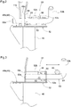
Fig. 2 is a front view of a lock mechanism in the locked state. -
Fig. 3 is a front view of a lock mechanism in the released state. -
Fig. 4 is a side view of a strut pole in the stored state. -
Fig. 5 is a left side view of a riding type mower in its entirety. -
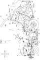
Fig. 6 is a plan view of a riding type mower in its entirety. -
Fig. 7 is a side view of a grass collecting container in the discharge orientation. -
Fig. 8 is a side view of a connection portion. -
Fig. 9 is a cross-sectional view of a connection portion. -
Fig. 10 is a front view of an operation valve device. -
Fig. 11 is a front view of a beta pin in the stored state. -
Fig. 12 is a diagram illustrating how a grass collecting apparatus is attached. -
Fig. 13 is a diagram illustrating how a grass collecting apparatus is attached. - The description below deals with an example embodiment of the present invention with reference to drawings.
- A support cart is used for a riding type mower to which a grass collecting apparatus is attachable and from which it is detachable, and helps the attachment and detachment of the grass collecting apparatus.
- In the description below of the vehicle body of a riding type mower, arrow F shown in
Figs. 5 and6 indicates the forward direction of the vehicle body, arrow B shown inFigs. 5 and6 indicates the backward direction of the vehicle body, arrow U shown inFig. 5 indicates the upward direction of the vehicle body, arrow D shown inFig. 5 indicates the downward direction of the vehicle body, arrow L shown inFig. 6 indicates the leftward direction of the vehicle body, and arrow R shown inFig. 6 indicates the rightward direction of the vehicle body. -
Figs. 5 and6 each illustrate a riding type mower A including (i) a vehicle body, (ii) a pair of left and rightfront wheels 1 provided for the vehicle body and configured to allow the riding type mower A to be steered, and (iii) a pair of left and right drivablerear wheels 2 provided for the vehicle body. The riding type mower A further includes, at a front portion of the vehicle body, amotor section 4 containing anengine 3 configured to produce power to be transmitted to therear wheels 2. The riding type mower A further includes, at a back portion of the vehicle body, adriver section 7 configured to accommodate a driver and containing a driver'sseat 5 and asteering wheel 6 configured to operate thefront wheels 1 to steer the riding type mower A. The riding type mower A is provided with amowing apparatus 8 between thefront wheels 1 and therear wheels 2 which mowingapparatus 8 is configured to reap grass or turf. Themowing apparatus 8 is driven by power transmitted from theengine 3. The riding type mower A is provided with, at a back portion of the vehicle body, agrass collecting apparatus 10 supported by the rear portion and including agrass collecting container 11. The riding type mower A is also provided with aconveyor duct 9 extending from themowing apparatus 8 to thegrass collecting container 11 and configured to convey grass or turf mown by the mowing apparatus 8 (hereinafter referred to collectively as "mown grass") to thegrass collecting container 11. Theconveyor duct 9 allows mown grass to be conveyed by a wind caused by rotation of acutting blade 8a of themowing apparatus 8. Theconveyor duct 9 extends under the vehicle body in its front-back direction through a space between the left and rightrear wheels 2. - The
grass collecting apparatus 10 is, as illustrated inFigs. 5 and6 , provided with agrass collecting container 11 and a lifting-loweringlink mechanism 12 allowing thegrass collecting container 11 to be supported by the vehicle body. - The lifting-lowering
link mechanism 12 extends backward from a support frame 13 (support section), which is present at a back portion of the vehicle body, in such a manner as to be capable of being swung in the up-down direction. The lifting-loweringlink mechanism 12 has an extension end connected to a lower back portion of thegrass collecting container 11 in such a manner that thegrass collecting container 11 is capable of being swung relative to the lifting-loweringlink mechanism 12. Thesupport frame 13 stands on respective back portions of left and right vehicle body frames 14 to function as a ROPS (Rollover Protection Structure). Thesupport frame 13 includes a pair of left and rightsupportive column portions 13a and aconnection portion 13b connecting respective upper portions of the left and rightsupportive column portions 13a to each other. Thegrass collecting container 11 is capable of, as a result of a swing of the lifting-loweringlink mechanism 12, being lowered to a collection position, which is a lower position relative to the vehicle body as illustrated inFig. 5 , and lifted to a discharge position, which is an upper position relative to the vehicle body as illustrated inFig. 7 . As illustrated inFig. 5 , thegrass collecting container 11 is, when at the collection position, (i) operated with use of a pair of left andright dump cylinders 15 to have a grass collecting orientation, in which thegrass collecting container 11 collects and stores mown grass from themowing apparatus 8, and (ii) supported by the lifting-loweringlink mechanism 12 while keeping the grass collecting orientation. As illustrated inFig. 7 , thegrass collecting container 11 is, when at the discharge position, (i) operated with use of the pair of left andright dump cylinders 15 to have a discharge orientation, in which thegrass collecting container 11 is inclined with a back portion lowered to discharge mown grass stored therein, and (ii) supported by the lifting-loweringlink mechanism 12 while keeping the discharge orientation. When thegrass collecting container 11 has been swung to have a discharge orientation, thedump cylinders 15 are operated to open thelid 11a, so that thegrass collecting container 11 has an open discharge port. The left andright dump cylinders 15 are, as illustrated inFigs. 5 and7 , respectively connected in an interlocking manner tooperation arms 17 extending respectively from the left and right ends of arotary shaft 16 of thegrass collecting container 11. Swinging theoperation arms 17 to rotate therotary shaft 16 changes how thegrass collecting container 11 is oriented. - Specifically, as illustrated in
Fig. 5 , the lifting-loweringlink mechanism 12 has a front end provided with aconnection section 18, which becomes detachably connected to thesupport frame 13 so that the lifting-loweringlink mechanism 12 becomes detachably supported by thesupport frame 13. As the front end of the lifting-loweringlink mechanism 12 is connected to theconnection section 18 in such a manner as to be capable of being swung in the up-down direction, the lifting-loweringlink mechanism 12 is supported by thesupport frame 13 in such a manner as to be capable of being swung in the up-down direction. - As illustrated in
Figs. 5 and6 , theconnection section 18 includes (i) aleft connection portion 18A detachably connected to the leftsupportive column portion 13a of thesupport frame 13 and (ii) aright connection portion 18A detachably connected to the rightsupportive column portion 13a of thesupport frame 13. The left andright connection portions 18A are, as illustrated inFigs. 8 and 9 , each shaped to form a groove and thereby cover the correspondingsupportive column portion 13a from backward. Theconnection portions 18A each have left and right connection sides each of which has two connection holes 19, one of which is present at an upper portion of the connection side, and the other of which is present at a lower portion of the connection side. The left andright connection portions 18A are each detachably connected to the correspondingsupportive column portion 13a with two connection pins 21 each detachably inserted through (i) one of the upper and lower connection holes 19 in theconnection portion 18A and (ii) acorresponding connection hole 20 in thesupportive column portion 13a. - The lifting-lowering
link mechanism 12, as illustrated inFigs. 5 and6 , includes a pair of left and rightlink mechanism portions 12A present on the opposite lateral sides of thegrass collecting container 11. The leftlink mechanism portion 12A includes anupper link 22 and alower link 23 each extending backward from theleft connection portion 18A in such a manner as to be capable of being swung in the up-down direction. The rightlink mechanism portion 12A includes anupper link 22 and alower link 23 each extending backward from theright connection portion 18A in such a manner as to be capable of being swung in the up-down direction. Theupper links 22 and thelower links 23 have respective back ends connected to alink connection portion 11b at a lower back portion of thegrass collecting container 11 in such a manner that thegrass collecting container 11 is capable of being swung relative to theupper links 22 and thelower links 23. - As illustrated in
Fig. 7 , the left andright connection portions 18A each have an upper portion provided with anupper support section 24, which pivotally supports a front end of the correspondingupper link 22 via apivot shaft 24a. The left andright connection portions 18A each have a lower portion provided with alower support section 25, which pivotally supports a front end of the correspondinglower link 23 via apivot shaft 25a. The left andright connection portions 18A are each provided with the correspondingupper support section 24 andlower support section 25 connected thereto. The left andright connection portions 18A are each a connection member supporting the respective front ends of the correspondingupper link 22 andlower link 23 in such a manner that the front ends are separated from each other by a predetermined distance. - The
connection section 18, as illustrated inFigs. 5 and9 , becomes connected to a connection portion connecting position on thesupport frame 13 as a result of the left andright connection portions 18A each becoming connected to the correspondingsupportive column portion 13a with use of two connection pins 21. Detaching the left andright connection portions 18A from the respectivesupportive column portions 13a detaches theconnection section 18 from thesupport frame 13. Connecting theconnection section 18 to thesupport frame 13 allows the lifting-loweringlink mechanism 12 to be supported by thesupport frame 13 in such a manner as to be capable of being swung in the up-down direction. Detaching theconnection section 18 from thesupport frame 13 detaches the lifting-loweringlink mechanism 12 from thesupport frame 13. - As illustrated in
Fig. 5 , thegrass collecting apparatus 10 includes a left lifting-loweringcylinder 26 that is connected to (i) an intermediate portion of thelower link 23 of the leftlink mechanism portion 12A and (ii) a lower portion of the leftsupportive column portion 13a of thesupport frame 13 and that is configured to lift and lower the leftlink mechanism portion 12A. Thegrass collecting apparatus 10 also includes a right lifting-loweringcylinder 26 that is connected to (i) an intermediate portion of thelower link 23 of the rightlink mechanism portion 12A and (ii) a lower portion of the rightsupportive column portion 13a of thesupport frame 13 and that is configured to lift and lower the rightlink mechanism portion 12A. The lifting-loweringlink mechanism 12 can be lifted and lowered as a result of (i) the leftlink mechanism portion 12A being lifted and lowered through extension and contraction of the left lifting-loweringcylinder 26 and (ii) the rightlink mechanism portion 12A being lifted and lowered through extension and contraction of the right lifting-loweringcylinder 26. The left and right lifting-loweringcylinders 26 each have a lower portion detachably supported by acylinder supporting section 27 provided for the correspondingsupportive column portion 13a. - As illustrated in
Fig. 10 , the riding type mower A includes anoperation valve device 30 detachably supported by the rightsupportive column portion 13a of thesupport frame 13 and configured to operate the left and right lifting-loweringcylinders 26 and the left andright dump cylinders 15. - Specifically, as illustrated in
Fig. 10 , the rightsupportive column portion 13a is provided with an operationvalve supporting section 31 having a pair of upper and lowersupportive elements 31a. Theoperation valve device 30 is provided with anattachment section 32, which has alateral side portion 32a provided with twoconnection shafts 33 extending downward from front and back portions thereof, respectively. Theattachment section 32 is supported by the operationvalve supporting section 31 with (i) the front andback connection shafts 33 inserted through two support holes in each of the upper and lowersupportive elements 31a from above in such a manner as to be capable of being pulled out and (ii) thelateral side portion 32a placed on and received by the upper face of the uppersupportive element 31a. Thefront connection shaft 33 is provided with abeta pin 34 detachably attached to a portion of thefront connection shaft 33 which portion is between the upper and lowersupportive elements 31a. Thebeta pin 34 prevents theattachment section 32 from becoming detached from the operationvalve supporting section 31. - When the
grass collecting apparatus 10 is to be detached from the vehicle body through detachment ofhydraulic hoses 35 provided for the vehicle body from theoperation valve device 30, thebeta pin 34 is detached from thefront connection shaft 33 to allow the front andback connection shafts 33 to be pulled out from the upper and lowersupportive elements 31a for detachment of theoperation valve device 30 from thesupport frame 13. In this case, thebeta pin 34 detached from thefront connection shaft 33 may, as illustrated inFig. 11 , be hung for storage on a ring-shapedpin holder 36 provided for the rightsupportive column portion 13a. Thepin holder 36 is detachably supported by a portion of one of the two connection pins 21 for the rightsupportive column portion 13a which portion protrudes inward from the rightsupportive column portion 13a. Thepin holder 36 is supported by theconnection pin 21 to be provided for the rightsupportive column portion 13a. -
Fig. 1 illustrates a support cart C including abase section 42, a pair of left and rightfront wheels 40 provided for thebase section 42, and a pair of left and rightrear wheels 41 provided for thebase section 42. Thefront wheels 40 and therear wheels 41 are each a caster wheel. Thebase section 42 is movable over a work floor G such as the ground (seeFig. 4 ) with use of thefront wheels 40 and therear wheels 41. - The
base section 42 includes a pair of left and right front-back frame bars 43 and a pair of front and back lateral frame bars 44, the front-back frame bars 43 and the lateral frame bars 44 being combined with each other into a frame in a plan view. The left and right front-back frame bars 43 each have a front portion provided with a front-wheel supportingframe bar 45 extending in the up-down direction of thebase section 42. The left and right front-back frame bars 43 each have a back portion provided with a rear-wheel supportingframe bar 46 extending in the up-down direction of thebase section 42. Thebase section 42 has an inner space defined by the pair of left and right front-back frame bars 43 and the pair of front and back lateral frame bars 44. Thebase section 42 is thus lightweight. Thebase section 42 for the present embodiment is in the shape of a rectangular frame in a plan view. The shape is, however, not limited to that. Thebase section 42 may alternatively be in the shape of a frame that is, for example, hexagonal or elliptical instead of rectangular. - The
front wheels 40 are each supported by a lower portion of the corresponding front-wheel supportingframe bar 45. Therear wheels 41 are each supported by a lower portion of the corresponding rear-wheel supportingframe bar 46. The left and right front-wheel supporting frame bars 45 are connected to each other by a frontreinforcement frame bar 47 extending therebetween. The left and right rear-wheel supporting frame bars 46 are connected to each other by a rearreinforcement frame bar 48 extending therebetween. - As illustrated in
Fig. 1 , thebase section 42 has an upper portion provided with aplacement section 49 on which thegrass collecting apparatus 10 is placed and by which thegrass collecting apparatus 10 is supported. Specifically, theplacement section 49 includes (i) a pair of left and right frontcontainer placement portions 49a provided for the frontlateral frame bar 44 and (ii) backcontainer placement portions 49b each provided for an upper portion of the corresponding one of the left and right rear-wheel supporting frame bars 46. The left and right backcontainer placement portions 49b are, as illustrated inFig. 4 , above the left and right frontcontainer placement portions 49a. The left and right front-wheel supporting frame bars 45 each have an upper portion provided with acylinder holding section 50 holding a lower portion of the corresponding lifting-loweringcylinder 26. - As illustrated in
Fig. 1 , thebase section 42 has a left side portion and a right side portion each provided with alock mechanism 51 configured to fix thegrass collecting apparatus 10 on theplacement section 49 to thebase section 42. Specifically, as illustrated inFig. 1 , theleft lock mechanism 51 is provided for the left backcontainer placement portion 49b, whereas theright lock mechanism 51 is provided for the right backcontainer placement portion 49b. As illustrated inFig. 2 , the left andright lock mechanisms 51 each include (i) aholder 52 extending from the corresponding backcontainer placement portion 49b laterally outward of the base section and (ii) alock member 53 supported in a support hole in alateral plate portion 52a of theholder 52 and a support hole in alateral wall portion 49c of the backcontainer placement portion 49b. Thelock member 53 is supported in such a manner as to be slidable in the width direction of the base section. Thelock member 53 is provided with alock spring 55 fitted around a portion thereof which portion is between (i) aspring receiving pin 54 provided for thelock member 53 and (ii) thelateral plate portion 52a of theholder 52. - The left and
right lock mechanisms 51 are each configured as follows: As illustrated inFig. 2 , when thelock member 53 has been slid by the urging force of thelock spring 55 inward of the base section so that thetip 53a of thelock member 53 has been inserted through a lock hole in thelink connection portion 11b of thegrass collecting container 11, thelock member 53 fixes thegrass collecting apparatus 10 to the base section 42 (locked state). As illustrated inFig. 3 , when thelock member 53 has been slid against the urging force of thelock spring 55 through operation of theoperation portion 53b at an end of thelock member 53 so that thetip 53a of thelock member 53 has been pulled out from the lock hole in thelink connection portion 11b, thelock member 53 releases thegrass collecting apparatus 10 from the base section 42 (released state). When thelock member 53 is in the released state, rotating thelock member 53 with use of theoperation portion 53b and hooking the tip of thespring receiving pin 54 on a notch 56 (positioning portion) in aback plate portion 52b of theholder 52 allows thelock member 53 to be kept in the released state against the urging force of thelock spring 55. - As illustrated in
Fig. 1 , thebase section 42 is provided with twostrut poles 60 configured to prop the lifting-loweringlink mechanism 12. One of thestrut poles 60 is present at a front left portion of thebase section 42, whereas the other of thestrut poles 60 is present at a front right portion of thebase section 42. Theleft strut pole 60 extends from asupport section 62 at an upper portion of the left front-wheel supportingframe bar 45, whereas theright strut pole 60 extends from asupport section 62 at an upper portion of the right front-wheel supportingframe bar 45. The left andright strut poles 60 each include an extension andcontraction adjusting portion 61. The extension andcontraction adjusting portion 61 is configured to adjust the length of that portion of thecorresponding strut pole 60 which extends from the position at which thestrut pole 60 is connected to thecorresponding support section 62 to aconnection portion 60a at the tip of thestrut pole 60. The extension andcontraction adjusting portions 61 for the present embodiment are each present at an intermediate portion of thecorresponding strut pole 60. The arrangement is, however, not limited to that. The extension andcontraction adjusting portions 61 may, for instance, alternatively be each present at a base end of thecorresponding strut pole 60 and integral with a portion for connection to thecorresponding support section 62. The extension andcontraction adjusting portions 61 may further alternatively be each present at an extension end of thecorresponding strut pole 60 and integral with thecorresponding connection portion 60a. The extension andcontraction adjusting portions 61 are each in the form of a turnbuckle. - The left and
right strut poles 60 are each supported by thecorresponding support section 62 in such a manner as to be capable of being swung in the up-down direction relative to the corresponding front-wheel supportingframe bar 45. Further, the left andright strut poles 60 are each supported in such a manner as to be capable of changing its orientation between (i) a strut orientation, in which thestrut pole 60 extends upward from thecorresponding support section 62 as illustrated inFig. 1 , and (ii) a storage orientation, in which thestrut pole 60 is inclined flat backward in comparison to the strut orientation as shown inFig. 4 with solid lines. - When the left and
right strut poles 60 are each in the strut orientation as illustrated inFig. 12 , thestrut pole 60 has its tip detachably connected to the correspondinglink mechanism portion 12A of the lifting-loweringlink mechanism 12 by means of thecorresponding connection portion 60a in such a manner as to prop the lifting-loweringlink mechanism 12. Theconnection portion 60a is connected to thelink mechanism portion 12A as a result of theconnection portion 60a being hooked in aconnection hole 63 in thelower link 23 of thelink mechanism portion 12A. Theconnection portion 60a hooked in theconnection hole 63 is prevented from becoming pulled out through attachment of a beta pin 65 (seeFig. 1 ) serving as a member for prevention of being pulled out. Theconnection portion 60a includes a bent tip of thestrut pole 60. The length of eachstrut pole 60 is adjusted with use of the corresponding extension andcontraction adjusting portion 61 so that the lifting-loweringlink mechanism 12 is swung to be adjusted relative to thegrass collecting container 11. This allows theconnection section 18 of the lifting-loweringlink mechanism 12 to be at the same height as that portion of thesupport frame 13 to which theconnection section 18 is to be connected. - When the
strut poles 60 are each in the storage orientation as illustrated inFig. 3 and shown inFig. 4 with solid lines, thestrut pole 60 has a tip-side portion hooked by a holdingportion 64 of thelock member 53 of thecorresponding lock mechanism 51 in the released state, so that thestrut pole 60 is held by thelock mechanism 51 in the storage orientation. The holdingportion 64 of thelock member 53 includes (i) a base end side portion, which is a portion of thelock member 53 which portion is present further outward of the base section than the correspondingholder 52 and (ii) anoperation portion 53b bent relative to the base end side portion. The base end side portion is configured to receive thecorresponding strut pole 60 from below, whereas theoperation portion 53b functions as a stopper configured to prevent thestrut pole 60 from becoming detached from the base end side portion. - The
grass collecting apparatus 10 can be attached to the vehicle body with use of the support cart C as follows:
As illustrated inFig. 12 , the support cart C is placed on a work floor G such as the ground. Thegrass collecting apparatus 10 is placed on theplacement section 49. The left andright lock mechanisms 51 are then operated into the locked state so that thegrass collecting apparatus 10 is fixed to thebase section 42 with use of therespective lock members 53 of the left andright lock mechanisms 51. Next, the left andright strut poles 60 are each operated into the strut orientation to prop the lifting-loweringlink mechanism 12. The respective lengths of the left andright strut poles 60 are each adjusted with use of the corresponding extension andcontraction adjusting portion 61 so that the lifting-loweringlink mechanism 12 is swung to be adjusted relative to thegrass collecting container 11 and that theconnection section 18 of the lifting-loweringlink mechanism 12 is at the same height as that portion of thesupport frame 13 to which theconnection section 18 is to be connected. The turnbuckle produces a jack function based on its screw threads, so that the correspondinglink mechanism portion 12A is easily lifted and lowered regardless of the load of thelink mechanism portion 12A. - Next, as illustrated in
Fig. 13 , the support cart C is moved from behind the vehicle body toward the vehicle body. Theconnection section 18 becomes engaged with thesupport frame 13, while the left and right lifting-loweringcylinders 26 each have a lower portion held by the correspondingcylinder holding section 50. When theconnection section 18 has engaged with thesupport frame 13, the upper and lower connection pins 21 are inserted through theconnection section 18 and thesupport frame 13, so that theconnection section 18 is connected to thesupport frame 13. - Next, the left and
right strut poles 60 are each detached from the correspondinglink mechanism portion 12A. The respective lower portions of the lifting-loweringcylinders 26 are each detached from the correspondingcylinder holding section 50, and are each connected to the correspondingcylinder supporting section 27 of thesupport frame 13 so that the lifting-loweringcylinders 26 are supported by thesupport frame 13. If theoperation valve device 30 is unattached, theattachment section 32 of theoperation valve device 30 is attached to the operationvalve supporting section 31 so that theoperation valve device 30 is supported by thesupport frame 13. Theoperation valve device 30 is then connected to thehydraulic hoses 35 provided for the vehicle body. - The
grass collecting apparatus 10 can be detached from the vehicle body through a process opposite to that of the attachment of thegrass collecting apparatus 10. - Specifically, when the lifting-lowering
link mechanism 12 is to be detached from thesupport frame 13, the respective lengths of thestrut poles 60 are each adjusted with use of the corresponding extension andcontraction adjusting portion 61 so that theconnection portion 60a of thestrut pole 60 coincides with theconnection hole 63 of the correspondinglower link 23. Thestrut poles 60 are then each connected to the correspondinglink mechanism portion 12A. This allows the lifting-loweringlink mechanism 12 to be supported by thestrut poles 60 even if the upper and lower connection pins 21 are pulled out. -
- (1) The embodiment described above is an example including left and
right strut poles 60. The embodiment may alternatively include only either a left orright strut pole 60. Specifically, the embodiment may be arranged as follows: The left and rightupper links 22 are connected to each other with use of anupper connection member 22a (seeFig. 6 ). The left and rightlower links 23 are connected to each other with use of alower connection member 23a (seeFig. 6 ). Propping only either the left or rightlink mechanism portion 12A with use of asingle strut pole 60 allows the entire lifting-loweringlink mechanism 12 to be propped. - (2) The embodiment described above is an example in which the
connection section 18 is provided withupper support sections 24 andlower support sections 25 and in which thestrut poles 60 are each connected to only the correspondinglower link 23. The arrangement is, however, not limited to that. The embodiment may, for instance, alternatively include a connection section provided with anupper support section 24 and a connection section provided with alower support section 25 for eachsupportive column portion 13a, the connection sections being separately connected to thesupport frame 13, and further include strut poles configured to prop theupper links 22 and thelower links 23 separately from each other. - (3) The embodiment described above is an example in which the extension and
contraction adjusting portions 61 are each in the form of a turnbuckle. The arrangement is, however, not limited to that. The extension andcontraction adjusting portions 61 may alternatively be each in the form of, for example, an extension and contraction element that combines a slide structure and a positioning screw or an extension and contraction element that combines a slide structure and a positioning pin. - (4) The embodiment described above is an example in which the
lock members 53 each include a holdingportion 64. The arrangement is, however, not limited to that. The embodiment may, for instance, alternatively include dedicated holding structures each configured to hold a tip-side portion of thecorresponding strut pole 60 in the storage orientation. - The present invention is applicable to a support cart for a riding type mower, the riding type mower including a mowing apparatus provided for the vehicle body and a grass collecting apparatus configured to be detachably supported by a support section at a back portion of the vehicle body, the grass collecting apparatus including (i) a grass collecting container, (ii) a connection section configured to be detachably connected to the support section, and (iii) a lifting-lowering link mechanism extending backward from the connection section in such a manner as to be capable of being swung in the up-down direction and supporting the grass collecting container in such a manner as to be capable of lifting and lowering the grass collecting container and changing the orientation of the grass collecting container between a grass collecting orientation and a discharge orientation.
-
- 8
- Mowing apparatus
- 10
- Grass collecting apparatus
- 11
- Grass collecting container
- 12
- Lifting-lowering link mechanism
- 13
- Support section (support frame)
- 18
- Connection section
- 22
- Upper link
- 23
- Lower link
- 24
- Upper support section
- 25
- Lower support section
- 42
- Base section
- 49
- Placement section
- 53
- Lock member
- 60
- Strut pole
- 61
- Extension and contraction adjusting portion
- 64
- Holding portion
- A
- Riding type mower
- G
- Work floor
Claims (5)
- A support cart (C) for a riding type mower (A),
the riding type mower including:a vehicle body;a mowing apparatus (8) provided for the vehicle body;a support section (13) at a back portion of the vehicle body; anda grass collecting apparatus (10) configured to be detachably supported by the support section,the grass collecting apparatus including:a grass collecting container (11) configured to receive grass mown by the mowing apparatus and store the grass;a connection section (18) configured to be detachably connected to the supporting portion; anda lifting-lowering link mechanism (12) extending backward from the connection section in such a manner as to be capable of being swung in an up-down direction and supporting the grass collecting container (11) in such a manner as to be capable of (i) lifting and lowering the grass collecting container and (ii) changing an orientation of the grass collecting container between a grass collecting orientation and a discharge orientation,the support cart (C) being for use in attaching the grass collecting apparatus to the riding type mower and detaching the grass collecting apparatus from the riding type mower,the support cart (C) comprising:a base section (42) configured to move on a work floor;a placement section (49) provided for the base section and configured to receive and support the grass collecting apparatus; anda strut pole (60) extending upward from the base section and configured to be switched between (i) a strut orientation, in which the strut pole props the lifting-lowering link mechanism, and (ii) a non-strut orientation, in which the strut pole does not prop the lifting-lowering link mechanism, whereinthe strut pole (60) includes an extension and contraction adjusting portion (61). - The support cart according to claim 1, wherein
the lifting-lowering link mechanism (12) includes an upper link (22) and a lower link (23),
the connection section (18) is provided with (i) an upper support section (24) connected to the connection section and pivotally supporting a front end of the upper link and (ii) a lower support section (25) connected to the connection section and pivotally supporting a front end of the lower link, and
the strut pole (60) is connected only to the lower link of the upper link and the lower link. - The support cart according to claim 1 or 2, wherein
the extension and contraction adjusting portion (61) includes a turnbuckle. - The support cart according to any one of claims 1 to 3, further comprising:a lock member (53) configured to be switched between (i) a locked state, in which the lock member fixes the grass collecting apparatus (10) on the placement section to the base section (42), and (ii) a released state, in which the lock member does not fix the grass collecting apparatus to the base section, whereinthe lock member (53) is supported by the base section in such a manner as to be capable of being slid between the locked state and the released state.
- The support cart according to claim 4, wherein
the strut pole (60) is configured to be switched into a storage orientation, in which the strut pole is inclined flat in comparison to the strut orientation, and
the lock member (53) includes a holding portion (64) configured to hook a tip-side portion of the strut pole in the storage orientation to hold the strut pole in the storage orientation.
Applications Claiming Priority (1)
| Application Number | Priority Date | Filing Date | Title |
|---|---|---|---|
| JP2020052470A JP7295056B2 (en) | 2020-03-24 | 2020-03-24 | support trolley |
Publications (2)
| Publication Number | Publication Date |
|---|---|
| EP3884763A1 true EP3884763A1 (en) | 2021-09-29 |
| EP3884763B1 EP3884763B1 (en) | 2025-11-26 |
Family
ID=73646097
Family Applications (1)
| Application Number | Title | Priority Date | Filing Date |
|---|---|---|---|
| EP20210503.7A Active EP3884763B1 (en) | 2020-03-24 | 2020-11-29 | Support cart |
Country Status (2)
| Country | Link |
|---|---|
| EP (1) | EP3884763B1 (en) |
| JP (1) | JP7295056B2 (en) |
Citations (3)
| Publication number | Priority date | Publication date | Assignee | Title |
|---|---|---|---|---|
| JP2013000105A (en) * | 2011-06-21 | 2013-01-07 | Iseki & Co Ltd | Mower |
| EP2559333A1 (en) * | 2011-08-18 | 2013-02-20 | Iseki & Co., Ltd. | Riding-type mower |
| EP3598887A2 (en) * | 2018-07-05 | 2020-01-29 | Kubota Corporation | Support carriage, riding grass mower having the support carriage, and work vehicle including the riding grass mower |
Family Cites Families (8)
| Publication number | Priority date | Publication date | Assignee | Title |
|---|---|---|---|---|
| US4487007A (en) * | 1983-06-27 | 1984-12-11 | Excel Industries, Inc. | Storage box for mower clippings |
| JPH0749847Y2 (en) * | 1989-07-26 | 1995-11-13 | ディエックスアンテナ株式会社 | Portable antenna |
| JP2002101722A (en) * | 2000-09-29 | 2002-04-09 | Kubota Corp | Riding mower |
| JP2005151874A (en) * | 2003-11-26 | 2005-06-16 | Sasaki Corporation | Mobile carriage device of agricultural implement to be linked to tractor |
| US7617663B1 (en) * | 2005-08-12 | 2009-11-17 | Humboldt Specialty Manufacturing Co. | Grass box discharge rear panel |
| JP5818508B2 (en) * | 2011-05-23 | 2015-11-18 | 三菱農機株式会社 | Work machine cart |
| JP2012249537A (en) * | 2011-05-31 | 2012-12-20 | Iseki & Co Ltd | Riding lawn mower |
| JP6902999B2 (en) * | 2017-12-27 | 2021-07-14 | 株式会社クボタ | Riding mower |
-
2020
- 2020-03-24 JP JP2020052470A patent/JP7295056B2/en active Active
- 2020-11-29 EP EP20210503.7A patent/EP3884763B1/en active Active
Patent Citations (4)
| Publication number | Priority date | Publication date | Assignee | Title |
|---|---|---|---|---|
| JP2013000105A (en) * | 2011-06-21 | 2013-01-07 | Iseki & Co Ltd | Mower |
| EP2559333A1 (en) * | 2011-08-18 | 2013-02-20 | Iseki & Co., Ltd. | Riding-type mower |
| JP2013039094A (en) | 2011-08-18 | 2013-02-28 | Iseki & Co Ltd | Riding mower |
| EP3598887A2 (en) * | 2018-07-05 | 2020-01-29 | Kubota Corporation | Support carriage, riding grass mower having the support carriage, and work vehicle including the riding grass mower |
Also Published As
| Publication number | Publication date |
|---|---|
| JP2021151192A (en) | 2021-09-30 |
| EP3884763B1 (en) | 2025-11-26 |
| JP7295056B2 (en) | 2023-06-20 |
Similar Documents
| Publication | Publication Date | Title |
|---|---|---|
| US5558169A (en) | Truck mounted work implement | |
| EP2965613B1 (en) | Header retaining system for a lateral transport center pivot agricultural machine | |
| US7168907B2 (en) | Latching system for automatically securing front-mounted loader mast to tractor-carried loader mounting frame | |
| US7992373B2 (en) | Lawn mower with grass collecting unit support | |
| EP3505686B1 (en) | Front loader | |
| EP2559333A1 (en) | Riding-type mower | |
| US4529215A (en) | Hydraulic cylinder safety lock | |
| US6776571B2 (en) | Fork attachment for backhoe | |
| EP3884763B1 (en) | Support cart | |
| US3554396A (en) | Front end loader | |
| EP0640726B1 (en) | Loader including a pair of transversely spaced upright posts | |
| AU6227180A (en) | Quick-coupling locking mechanism | |
| US5857314A (en) | Mower with an improved set-down member | |
| US11255069B2 (en) | Front loader | |
| EP2310578B1 (en) | Locking device for securing a backhoe attachment to a carrier lift arm | |
| WO2000044217A1 (en) | Mounting frame for use with three point hitch | |
| US20110180282A1 (en) | Wrap around dozer blade hitch | |
| US3043375A (en) | Removable hoisting attachment for tractors | |
| KR20150033817A (en) | Front loader and front loader with a Agricultural | |
| US2736152A (en) | Vehicle-attachable agricultural machine unit | |
| USRE22991E (en) | Implement construction | |
| KR102040980B1 (en) | Tractor attachment detachable device | |
| KR200296583Y1 (en) | Coupling structure of tractor bucket | |
| EP3366105B1 (en) | Riding-type mower | |
| JP2001152478A (en) | Mounting system |
Legal Events
| Date | Code | Title | Description |
|---|---|---|---|
| PUAI | Public reference made under article 153(3) epc to a published international application that has entered the european phase |
Free format text: ORIGINAL CODE: 0009012 |
|
| STAA | Information on the status of an ep patent application or granted ep patent |
Free format text: STATUS: REQUEST FOR EXAMINATION WAS MADE |
|
| 17P | Request for examination filed |
Effective date: 20201129 |
|
| AK | Designated contracting states |
Kind code of ref document: A1 Designated state(s): AL AT BE BG CH CY CZ DE DK EE ES FI FR GB GR HR HU IE IS IT LI LT LU LV MC MK MT NL NO PL PT RO RS SE SI SK SM TR |
|
| STAA | Information on the status of an ep patent application or granted ep patent |
Free format text: STATUS: EXAMINATION IS IN PROGRESS |
|
| 17Q | First examination report despatched |
Effective date: 20240610 |
|
| GRAP | Despatch of communication of intention to grant a patent |
Free format text: ORIGINAL CODE: EPIDOSNIGR1 |
|
| STAA | Information on the status of an ep patent application or granted ep patent |
Free format text: STATUS: GRANT OF PATENT IS INTENDED |
|
| INTG | Intention to grant announced |
Effective date: 20250620 |
|
| GRAS | Grant fee paid |
Free format text: ORIGINAL CODE: EPIDOSNIGR3 |
|
| GRAA | (expected) grant |
Free format text: ORIGINAL CODE: 0009210 |
|
| STAA | Information on the status of an ep patent application or granted ep patent |
Free format text: STATUS: THE PATENT HAS BEEN GRANTED |
|
| AK | Designated contracting states |
Kind code of ref document: B1 Designated state(s): AL AT BE BG CH CY CZ DE DK EE ES FI FR GB GR HR HU IE IS IT LI LT LU LV MC MK MT NL NO PL PT RO RS SE SI SK SM TR |
|
| REG | Reference to a national code |
Ref country code: CH Ref legal event code: F10 Free format text: ST27 STATUS EVENT CODE: U-0-0-F10-F00 (AS PROVIDED BY THE NATIONAL OFFICE) Effective date: 20251126 Ref country code: GB Ref legal event code: FG4D |
|
| REG | Reference to a national code |
Ref country code: DE Ref legal event code: R096 Ref document number: 602020062700 Country of ref document: DE |
|
| REG | Reference to a national code |
Ref country code: IE Ref legal event code: FG4D |
|
| PGFP | Annual fee paid to national office [announced via postgrant information from national office to epo] |
Ref country code: FR Payment date: 20251118 Year of fee payment: 6 |
|
| REG | Reference to a national code |
Ref country code: NL Ref legal event code: MP Effective date: 20251126 |
|
| PG25 | Lapsed in a contracting state [announced via postgrant information from national office to epo] |
Ref country code: ES Free format text: LAPSE BECAUSE OF FAILURE TO SUBMIT A TRANSLATION OF THE DESCRIPTION OR TO PAY THE FEE WITHIN THE PRESCRIBED TIME-LIMIT Effective date: 20251126 |
|
| REG | Reference to a national code |
Ref country code: LT Ref legal event code: MG9D |
|
| PG25 | Lapsed in a contracting state [announced via postgrant information from national office to epo] |
Ref country code: NO Free format text: LAPSE BECAUSE OF FAILURE TO SUBMIT A TRANSLATION OF THE DESCRIPTION OR TO PAY THE FEE WITHIN THE PRESCRIBED TIME-LIMIT Effective date: 20260226 |
|
| PGFP | Annual fee paid to national office [announced via postgrant information from national office to epo] |
Ref country code: DE Payment date: 20251231 Year of fee payment: 6 |
|
| PG25 | Lapsed in a contracting state [announced via postgrant information from national office to epo] |
Ref country code: HR Free format text: LAPSE BECAUSE OF FAILURE TO SUBMIT A TRANSLATION OF THE DESCRIPTION OR TO PAY THE FEE WITHIN THE PRESCRIBED TIME-LIMIT Effective date: 20251126 Ref country code: AT Free format text: LAPSE BECAUSE OF FAILURE TO SUBMIT A TRANSLATION OF THE DESCRIPTION OR TO PAY THE FEE WITHIN THE PRESCRIBED TIME-LIMIT Effective date: 20251126 Ref country code: FI Free format text: LAPSE BECAUSE OF FAILURE TO SUBMIT A TRANSLATION OF THE DESCRIPTION OR TO PAY THE FEE WITHIN THE PRESCRIBED TIME-LIMIT Effective date: 20251126 |
|
| REG | Reference to a national code |
Ref country code: AT Ref legal event code: MK05 Ref document number: 1860083 Country of ref document: AT Kind code of ref document: T Effective date: 20251126 |
|
| PG25 | Lapsed in a contracting state [announced via postgrant information from national office to epo] |
Ref country code: NL Free format text: LAPSE BECAUSE OF FAILURE TO SUBMIT A TRANSLATION OF THE DESCRIPTION OR TO PAY THE FEE WITHIN THE PRESCRIBED TIME-LIMIT Effective date: 20251126 |
|
| PG25 | Lapsed in a contracting state [announced via postgrant information from national office to epo] |
Ref country code: RS Free format text: LAPSE BECAUSE OF FAILURE TO SUBMIT A TRANSLATION OF THE DESCRIPTION OR TO PAY THE FEE WITHIN THE PRESCRIBED TIME-LIMIT Effective date: 20260226 |
|
| PG25 | Lapsed in a contracting state [announced via postgrant information from national office to epo] |
Ref country code: IS Free format text: LAPSE BECAUSE OF FAILURE TO SUBMIT A TRANSLATION OF THE DESCRIPTION OR TO PAY THE FEE WITHIN THE PRESCRIBED TIME-LIMIT Effective date: 20260326 |
|
| PG25 | Lapsed in a contracting state [announced via postgrant information from national office to epo] |
Ref country code: PT Free format text: LAPSE BECAUSE OF FAILURE TO SUBMIT A TRANSLATION OF THE DESCRIPTION OR TO PAY THE FEE WITHIN THE PRESCRIBED TIME-LIMIT Effective date: 20260326 |
|
| PG25 | Lapsed in a contracting state [announced via postgrant information from national office to epo] |
Ref country code: PL Free format text: LAPSE BECAUSE OF FAILURE TO SUBMIT A TRANSLATION OF THE DESCRIPTION OR TO PAY THE FEE WITHIN THE PRESCRIBED TIME-LIMIT Effective date: 20251126 |
|
| PG25 | Lapsed in a contracting state [announced via postgrant information from national office to epo] |
Ref country code: LV Free format text: LAPSE BECAUSE OF FAILURE TO SUBMIT A TRANSLATION OF THE DESCRIPTION OR TO PAY THE FEE WITHIN THE PRESCRIBED TIME-LIMIT Effective date: 20251126 |
|
| PG25 | Lapsed in a contracting state [announced via postgrant information from national office to epo] |
Ref country code: BG Free format text: LAPSE BECAUSE OF FAILURE TO SUBMIT A TRANSLATION OF THE DESCRIPTION OR TO PAY THE FEE WITHIN THE PRESCRIBED TIME-LIMIT Effective date: 20251126 |