EP3884098B1 - Sewing machine - Google Patents
Sewing machine Download PDFInfo
- Publication number
- EP3884098B1 EP3884098B1 EP19886558.6A EP19886558A EP3884098B1 EP 3884098 B1 EP3884098 B1 EP 3884098B1 EP 19886558 A EP19886558 A EP 19886558A EP 3884098 B1 EP3884098 B1 EP 3884098B1
- Authority
- EP
- European Patent Office
- Prior art keywords
- actuator element
- stitching
- coupler
- sewing machine
- head
- Prior art date
- Legal status (The legal status is an assumption and is not a legal conclusion. Google has not performed a legal analysis and makes no representation as to the accuracy of the status listed.)
- Active
Links
Images



Classifications
-
- D—TEXTILES; PAPER
- D05—SEWING; EMBROIDERING; TUFTING
- D05B—SEWING
- D05B3/00—Sewing apparatus or machines with mechanism for lateral movement of the needle or the work or both for making ornamental pattern seams, for sewing buttonholes, for reinforcing openings or for fastening articles, e.g. buttons, by sewing
-
- D—TEXTILES; PAPER
- D05—SEWING; EMBROIDERING; TUFTING
- D05B—SEWING
- D05B19/00—Program-controlled sewing machines
- D05B19/02—Sewing machines having electronic memory or microprocessor control unit
- D05B19/12—Sewing machines having electronic memory or microprocessor control unit characterised by control of operation of machine
- D05B19/14—Control of needle movement, e.g. varying amplitude or period of needle movement
-
- D—TEXTILES; PAPER
- D05—SEWING; EMBROIDERING; TUFTING
- D05B—SEWING
- D05B55/00—Needle holders; Needle bars
- D05B55/14—Needle-bar drives
-
- D—TEXTILES; PAPER
- D05—SEWING; EMBROIDERING; TUFTING
- D05B—SEWING
- D05B57/00—Loop takers, e.g. loopers
- D05B57/30—Driving-gear for loop takers
-
- D—TEXTILES; PAPER
- D05—SEWING; EMBROIDERING; TUFTING
- D05B—SEWING
- D05B69/00—Driving-gear; Control devices
- D05B69/10—Electrical or electromagnetic drives
- D05B69/12—Electrical or electromagnetic drives using rotary electric motors
Definitions
- the following description relates to sewing machines and, more specifically, to a sewing machine with fully rotatable sewing heads.
- a sewing machine for sewing a stitch into an article.
- the sewing machine includes first and second heads, which are each movable relative to the article, a first head and a second head.
- the first head includes a coupler rotatable about an axis extending through the first and second heads, a first actuator element to rotate with the coupler and to translate relative to the coupler in first and second directions transverse to the axis, a second actuator element to rotate with the coupler, to translate in the first and second directions with the first actuator element and to rotate relative to the first actuator element about an axis along a third direction and a third actuator element to rotate with the coupler, to translate in the first and second directions with the first actuator element, to rotate with the second actuator element about the axis along the third direction and to translate relative to the second actuator element in the third direction.
- the second head includes a coupler rotatable about the axis in the third direction, a first actuator element to rotate with the coupler and to translate relative to the coupler in the first and second directions and a second actuator element to rotate with the coupler, to translate in the first and second directions with the first actuator element, and to translate relative to the first actuator element in the third direction.
- the first head includes first and second stitching elements.
- the first stitching element includes a looper or a spreader and the second stitching element includes a punch or awl.
- the first actuator element drives translations of the first stitching element relative to the coupler of the first head in the first and second directions
- the second actuator element drives rotations of the first stitching element relative to the first actuation element
- the third actuator element drives translations of the second stitching element relative to the first stitching element in the third direction.
- a controller is configured to control and coordinate rotations of the coupler and translations and rotations of stitching elements of each of the first and second heads.
- the controller includes a scanner to scan positions of a feature on the article and is configured correct for deviations between actual and allowable needle positions in accordance with predefined stitching instructions and the positions of the feature.
- a first stitching element of the first head includes a looper or a spreader and a second stitching element of the first head includes a punch or awl.
- a first stitching element of the second head includes a needle.
- first and second heads are coupled to first and second independently articulable robotic arms.
- the first and second heads are coupled to a support structure.
- the support structure includes a spine and first and second elongate members extending from the spine, the first and second elongate members having distal ends to which the first and second heads are coupled, respectively.
- a sewing machine is provided with capabilities that meet current sewing demands.
- the sewing machine is intended for use in automated stitching applications and incorporates independent but synchronized upper and lower head rotations to eliminate a need to locate a machine body at a position perpendicular to the sewing path at all times.
- an ability to sew closed loop stitch paths is enhanced as is the capability to stitch curves having smaller radii into remote areas of a part.
- the sewing machine includes sewing heads that are each capable of +/-360° rotation and movement which can be driven mechanically, electro-mechanically or completely electrically.
- the sewing machine is designed such that the sewing heads are compact in size to allow for maximum maneuverability around a part.
- Functional capabilities of the machine are enhanced such that the following stitching technologies can be executed with only minor machine reconfiguration: single or double needle double thread chain stitch through soft materials; single or double needle single thread chain stitch through soft materials; single or double needle single thread chain stitch through rigid substrates; and single needle multi-thread embroidery stitching through soft materials.
- the sewing machine can also be designed such that the sewing heads can be decoupled with upper and lower heads attached to separate robots for further application flexibility.
- the sewing machine 101 includes a support structure 110, which is movable relative to the article 102 and which is rotatable about an axis A1 that extends through the article 102.
- the support structure 110 is movable in forward and back directions (i.e., first directions defined axially relative to the axis A3), side to side directions (i.e., second directions defined axially relative to the axis A1) and up and down directions (i.e., third directions defined axially relative to the axis A2).
- the support structure 110 may include a spine 111, a first elongate member 112 extending from a first end of the spine 111 and a second elongate member 113 extending from a second end of the spine 111 to be substantially parallel with the first elongate member 112.
- the first elongate member 112 has a distal end 114 at its far end from the spine 111 and the second elongate member 113 has a distal end 115 at its far end from the spine 111.
- the sewing machine 101 further includes a first stitching head 120, which is coupled to the support structure 110 at the distal end 114 of the first elongate member 112 and a second stitching head 130, which is coupled to the support structure 110 at the distal end 115 of the second elongate member 113.
- the first stitching head 120 can include or be provided with a first stitching element 1200.
- the first stitching element 1200 can include a needle.
- the second stitching head 130 can include or be provided with a second stitching element 1300.
- the second stitching element 1300 can include a looper.
- the sewing machine 101 also includes a first actuation assembly 140, a second actuation assembly 150 and, in some cases, a third actuation assembly 160.
- the first actuation assembly 140 is at least partially disposed within the support structure 110 and is configured to actuate sewing element 1200 of the first stitching head 120 and the sewing element 1300 of the second stitching head 130. Actuation of the sewing element 1200 occurs axially along axis A2 while actuation of the sewing element 1300 occurs rotationally about an axis in parallel to axis A1.
- the first actuation assembly 140 includes a motor 141, a mechanical linkage 142 that extends through the support structure 110, a first coupling unit 143 by which the mechanical linkage 142 is coupled to the first stitching head 120 and a second coupling unit 144 by which the mechanical linkage 142 is coupled to the second stitching head 130.
- the second actuation assembly 150 is at least partially disposed within the support structure 110 and is configured to drive respective rotations of each of the first stitching head 120 and the second stitching head 130 about axis A2.
- the second actuation assembly 150 includes a motor 151, a mechanical linkage 152 that extends through the support structure 110, a first coupling unit 153 by which the mechanical linkage152 is coupled to the first stitching head 120 and a second coupling unit 154 by which the mechanical linkage 152 is coupled to the second stitching head 130.
- the third actuation assembly 160 is configured to drive rotations of the support structure 110 about a second axis A1, such that the first stitching head 120 can operate above or below the article 102 and the second stitching head 130 can operate below or above the article 102.
- the sewing machine 101 may further include a scanner 170 that, prior to sewing, is configured to detect the relative position of a feature on the article 102 located along the stitch path, and provide feedback to the robot controller which in turn will adjust the coordinates of the predefined stitch path prior to sewing, resulting in part sewn in compliance with predefined stitching constraints.
- a sewing machine 201 is provided for sewing a stitch into an article 202.
- the sewing machine 201 includes a support structure 210, which is movable relative to the article 202.
- the support structure 210 is movable in forward and back directions (i.e., first directions defined linearly relative to axis A3), side to side directions (i.e., second directions defined linearly relative to the axis A1) and up and down directions (i.e., third directions defined linearly along the axis A2).
- the support structure 210 is also rotatable about the axis A1 and the article 202.
- the support structure 210 may include a spine 211, a first elongate member 212 extending from a first end of the spine 211 and a second elongate member 213 extending from a second end of the spine 211 to be substantially parallel with the first elongate member 212.
- the first elongate member 212 has a distal end 214 at its far end from the spine 211 and the second elongate member 213 has a distal end 215 at its far end from the spine 211.
- the sewing machine 201 further includes a first stitching head 220, a second stitching head 230 and a drive assembly 240.
- the first stitching head 220 is coupled to the support structure 210 at the distal end 214 of the first elongate member 212.
- the second stitching head 230 is coupled to the support structure 210 at the distal end 215 of the second elongate member 213.
- the first stitching head comprises a first stitching element 2200 and a second stitching element 2201.
- the first stitching element 2200 can include a looper or a spreader.
- the second stitching element 2201 can consist of a punch or awl.
- the second stitching head 230 can include or be provided with a third stitching element 2300.
- the third stitching element 2300 can include a needle.
- the first stitching head 220 includes a coupler 221, a first actuator element 222, which is rotatable with coupler 221 about axis A2 and which is translatable relative to the coupler 221 in the first and second directions, a second actuator element 223 and a third actuator element 224.
- the second actuator element 223 is translatable with the first actuator element 222 in the second and first directions along axes A1 and A3, is rotatable relative to the first actuator element 222 about axis A2 and is also rotatable with coupler 221 about the axis A2.
- the third actuator element 224 translates the second stitching element 2201 relative to second actuator element 223 in the third direction along the axis A2, is translatable with the first actuator element 222, is rotatable with the second actuator element 223 about the axis A2 and is also rotatable with the coupler 221 about the axis A2.
- the second stitching body 230 includes a coupler 231, a first actuator element 232, which is rotatable with coupler 231 about the axis A2 and which is translatable relative to the coupler 231 in the first and second directions along axes A3 and A1, and a second actuator element 233.
- the second actuator element 233 is translatable with the first actuator element 232 in the second and first directions along axes A1 and A3, is translatable relative to the first actuator element 232 in the third direction along the axis A2 and is rotatable with the coupler 231 about axis A2.
- the drive assembly 240 is at least partially disposed within the support structure 210 to drive rotations of the first and second stitching heads 220 and 230 about the axis A2.
- the actuation assembly 240 includes a motor 241, a mechanical linkage 242 that extends through the support structure 210, a first coupling unit 243 by which the mechanical linkage 242 is coupled to the first stitching head 220 and a second coupling unit 244 by which the mechanical linkage 242 is coupled to the second stitching head 230.
- An additional drive assembly 270 is provided to drive rotations of the support structure 210 about the axis A1 during sewing.
- the additional actuation assembly 270 is also utilized to drive the rotations of the support structure 210 about the second axis A2 such that the first stitching head 220 can operate above or below the article 202 and the second stitching head 230 can operate below or above the article 202.
- the sewing machine 201 may further include a scanner 280 that, prior to sewing, is configured to detect the relative position of a feature on the article 202 located along the stitch path, and provide feedback to the robot controller which in turn will adjust the coordinates of the predefined stitch path prior to sewing, resulting in part sewn in compliance with predefined stitching constraints.
- a scanner 280 that, prior to sewing, is configured to detect the relative position of a feature on the article 202 located along the stitch path, and provide feedback to the robot controller which in turn will adjust the coordinates of the predefined stitch path prior to sewing, resulting in part sewn in compliance with predefined stitching constraints.
- a sewing machine 301 is provided for sewing a stitch into an article 302.
- the sewing machine 301 includes a first head 310, which is movable relative to the article 302, and a second head 320, which is movable relative to the article 302.
- the first head 310 includes a first actuator element 311, which is rotatable about an axis A2 extending through the article 302 and the first and second heads 310 and 320, a second actuator element 312, a third actuator element 314, a fourth actuator element 315, and a first stitching element 313 that includes a looper or a spreader.
- the second actuator element 312 rotates with the first actuator element 311 and is translatable relative to the first actuator element 311 in first and second directions along axes A3 and A1 directions.
- the fourth actuator element 315 translates a second stitching element 3130 in the third direction along the axis A2, rotates with the first actuator element 311, translates with second actuator element 312 and rotates with the third actuator element 314.
- the second head 320 includes a first actuator element 321, which is rotatable about the axis A2, a second actuator element 322 and a third actuator element 323.
- the second actuator element 322 rotates with the first actuator element 321 and is translatable relative to the first actuator element 321 in the first and second directions along the axes A3 and A1.
- the third actuator element 323 includes a third stitching element 3230 and rotates with the first actuator element 321, translates in the first and second directions along axes A3 and A1 with the second actuator element 322 and is translatable relative to the second actuator element 322 in the third direction along the axis A2.
- the sewing machine 301 may further include a scanner 330 that, prior to sewing, is configured to detect the relative position of a feature on the article 302 located along the stitch path, and provide feedback to the robot controller which in turn will adjust the coordinates of the predefined stitch path prior to sewing, resulting in part sewn in compliance with predefined stitching constraints.
- a scanner 330 that, prior to sewing, is configured to detect the relative position of a feature on the article 302 located along the stitch path, and provide feedback to the robot controller which in turn will adjust the coordinates of the predefined stitch path prior to sewing, resulting in part sewn in compliance with predefined stitching constraints.
- the sewing machine 301 may be connected, via tool changers 340 and 350, to first and second independently articulable robotic arms 360 and 370 to which the first and second heads 310 and 320 are coupled, respectively.
- the robotic arms 360 and 370 can allow the first and second heads 310 and 320 to operate at various positions and attitudes relative to the article 302 and to be disposed above or below the article 302.
- the first and second heads 310 and 320 can be coupled to a support structure 360.
- the support structure 360 may include a spine 361, a first elongate member 362 extending from a first end of the spine 361 and a second elongate member 363 extending from a second end of the spine 361 to be substantially parallel with the first elongate member 362.
- the first elongate member 362 has a distal end 364 to which is the first head 310 is coupled at its far end from the spine 361 and the second elongate member 363 has a distal end 365 to which the second head 320 is coupled at its far end from the spine 361.
- Additional drive assembly 370 is provided to drive rotations of the support structure 360 about axis A1, as required in order to position the sewing machine 301 in it optimal position for stitching.
- the robot controller can be configured to drive the rotations of the support structure 360 about the axis A1 such that the first head 310 can operate above or below the article 302 and the second head 320 can operate below or above the article 302.
- a sewing machine incorporating upper and lower sewing heads for use in automated stitching applications to eliminate a need to locate a machine body at a position perpendicular to the sewing path at all times and to enhance an ability to sew closed loop stitch paths and curves having small radii, such as the case when embroidering.
- the sewing machine provides for closed loop chain stitch patterns on large contoured parts that have no internal feature openings (which are normally required for sewing head access) as well as start and stop positions that are perfectly aligned to create the effect of multiple components sewn together.
- the sewing machine also provides for intricate and complex chain stitch patterns that are placed on large countered parts, stitching capabilities around entire perimeter and interior portions of such products (where the products contains minimal or no openings internal to the part for sewing head access) and patterns that can be programmed to create an image, logo or text on products (embroidery) requiring very tight directional changes and turning radii (e.g., in-plane turning radii or the stitch turning radius on the surface of the flat or contoured part of less than 5 mm and in some cases less than 2 mm) where the turning radii is dictated by stitch length and an ability to rotate/turn the needle and hook within short periods of time and over short distances.
- turning radii e.g., in-plane turning radii or the stitch turning radius on the surface of the flat or contoured part of less than 5 mm and in some cases less than 2 mm
Landscapes
- Engineering & Computer Science (AREA)
- Textile Engineering (AREA)
- Computer Hardware Design (AREA)
- Microelectronics & Electronic Packaging (AREA)
- Physics & Mathematics (AREA)
- Electromagnetism (AREA)
- Mechanical Engineering (AREA)
- Sewing Machines And Sewing (AREA)
Description
- The following description relates to sewing machines and, more specifically, to a sewing machine with fully rotatable sewing heads.
- Currently, application of a decorative live stitch to pre-shaped automotive components can be accomplished via manual or automated stitching methods. Manual stitching is normally utilized on smaller components with relatively linear stitch paths. As part size, weight and stitch path complexity increase, it becomes more difficult for an operator to manually articulate the pre-shaped part under a stationary sewing machine and thus automation becomes more practical. An automated cell using a six-axis robot is commonly utilized with a sewing machine as the end effector. The sewing machine is designed to access required areas of the part within the range of motion of the robot.
- As the trend to apply live stitching to pre-shaped automotive components continues to gain in popularity, the placement and type of stitching required is evolving as well. As the desired stitch path increases in length and/or covers a larger portion of the shaped part surface, additional movement of the sewing head around the outside of the part is required. Movement the sewing head around the outside of the part can present a problem when fixturing the part, however, and the movement can often exceed a range of motion of the robot as well. In addition, automotive manufacturers often prefer unique stitch types, patterns and thread sizes that are not easily provided by conventional sewing systems. Examples of prior art sewing machines are disclosed in
US 2018313012 A1 ,US5875726 A ,US 2018080155 A1 ,US 4787326 A andUS 4557206 A . - According to the invention, a sewing machine for sewing a stitch into an article is provided. The sewing machine includes first and second heads, which are each movable relative to the article, a first head and a second head. The first head includes a coupler rotatable about an axis extending through the first and second heads, a first actuator element to rotate with the coupler and to translate relative to the coupler in first and second directions transverse to the axis, a second actuator element to rotate with the coupler, to translate in the first and second directions with the first actuator element and to rotate relative to the first actuator element about an axis along a third direction and a third actuator element to rotate with the coupler, to translate in the first and second directions with the first actuator element, to rotate with the second actuator element about the axis along the third direction and to translate relative to the second actuator element in the third direction. The second head includes a coupler rotatable about the axis in the third direction, a first actuator element to rotate with the coupler and to translate relative to the coupler in the first and second directions and a second actuator element to rotate with the coupler, to translate in the first and second directions with the first actuator element, and to translate relative to the first actuator element in the third direction.
- In accordance with the invention, the first head includes first and second stitching elements.
- In accordance with embodiments, the first stitching element includes a looper or a spreader and the second stitching element includes a punch or awl.
- In accordance with additional or alternative embodiments, the first actuator element drives translations of the first stitching element relative to the coupler of the first head in the first and second directions, the second actuator element drives rotations of the first stitching element relative to the first actuation element and the third actuator element drives translations of the second stitching element relative to the first stitching element in the third direction.
- In accordance with additional or alternative embodiments, a controller is configured to control and coordinate rotations of the coupler and translations and rotations of stitching elements of each of the first and second heads.
- In accordance with additional or alternative embodiments, the controller includes a scanner to scan positions of a feature on the article and is configured correct for deviations between actual and allowable needle positions in accordance with predefined stitching instructions and the positions of the feature.
- In accordance with additional or alternative embodiments, a first stitching element of the first head includes a looper or a spreader and a second stitching element of the first head includes a punch or awl.
- In accordance with additional or alternative embodiments, a first stitching element of the second head includes a needle.
- In accordance with additional or alternative embodiments, the first and second heads are coupled to first and second independently articulable robotic arms.
- In accordance with additional or alternative embodiments, the first and second heads are coupled to a support structure.
- In accordance with additional or alternative embodiments, the support structure includes a spine and first and second elongate members extending from the spine, the first and second elongate members having distal ends to which the first and second heads are coupled, respectively.
- These and other advantages and features will become more apparent from the following description taken in conjunction with the drawings.
- The subject matter, which is regarded as the disclosure, is particularly pointed out and distinctly claimed in the claims at the conclusion of the specification. The foregoing and other features and advantages of the disclosure are apparent from the following detailed description taken in conjunction with the accompanying drawings in which:
-
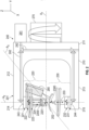
FIG. 1 is a side view of a mechanically driven sewing machine not according to the claimed invention; -
FIG. 2 is a side view of an electrically and mechanically driven sewing machine in accordance with embodiments; -
FIG. 3 is a side view of an electrically driven sewing machine in accordance with embodiments; and -
FIG. 4 is a side view of the sewing machine ofFIG. 3 with a support structure in accordance with embodiments. - These and other advantages and features will become more apparent from the following description taken in conjunction with the drawings.
- As will be described below, a sewing machine is provided with capabilities that meet current sewing demands. The sewing machine is intended for use in automated stitching applications and incorporates independent but synchronized upper and lower head rotations to eliminate a need to locate a machine body at a position perpendicular to the sewing path at all times. As a result, an ability to sew closed loop stitch paths is enhanced as is the capability to stitch curves having smaller radii into remote areas of a part. The sewing machine includes sewing heads that are each capable of +/-360° rotation and movement which can be driven mechanically, electro-mechanically or completely electrically. The sewing machine is designed such that the sewing heads are compact in size to allow for maximum maneuverability around a part. Functional capabilities of the machine are enhanced such that the following stitching technologies can be executed with only minor machine reconfiguration: single or double needle double thread chain stitch through soft materials; single or double needle single thread chain stitch through soft materials; single or double needle single thread chain stitch through rigid substrates; and single needle multi-thread embroidery stitching through soft materials. The sewing machine can also be designed such that the sewing heads can be decoupled with upper and lower heads attached to separate robots for further application flexibility.
- With reference to
FIG. 1 , asewing machine 101, not according to the claimed invention, is described and is capable of sewing various types of stitches into anarticle 102. Thesewing machine 101 includes asupport structure 110, which is movable relative to thearticle 102 and which is rotatable about an axis A1 that extends through thearticle 102. Thesupport structure 110 is movable in forward and back directions (i.e., first directions defined axially relative to the axis A3), side to side directions (i.e., second directions defined axially relative to the axis A1) and up and down directions (i.e., third directions defined axially relative to the axis A2). - In accordance with examples, the
support structure 110 may include aspine 111, a firstelongate member 112 extending from a first end of thespine 111 and a secondelongate member 113 extending from a second end of thespine 111 to be substantially parallel with the firstelongate member 112. The firstelongate member 112 has adistal end 114 at its far end from thespine 111 and the secondelongate member 113 has adistal end 115 at its far end from thespine 111. - The
sewing machine 101 further includes afirst stitching head 120, which is coupled to thesupport structure 110 at thedistal end 114 of the firstelongate member 112 and asecond stitching head 130, which is coupled to thesupport structure 110 at thedistal end 115 of the secondelongate member 113. Thefirst stitching head 120 can include or be provided with afirst stitching element 1200. Thefirst stitching element 1200 can include a needle. Thesecond stitching head 130 can include or be provided with asecond stitching element 1300. Thesecond stitching element 1300 can include a looper. - The
sewing machine 101 also includes afirst actuation assembly 140, asecond actuation assembly 150 and, in some cases, athird actuation assembly 160. - The
first actuation assembly 140 is at least partially disposed within thesupport structure 110 and is configured to actuatesewing element 1200 of thefirst stitching head 120 and thesewing element 1300 of thesecond stitching head 130. Actuation of thesewing element 1200 occurs axially along axis A2 while actuation of thesewing element 1300 occurs rotationally about an axis in parallel to axis A1.Thefirst actuation assembly 140 includes amotor 141, amechanical linkage 142 that extends through thesupport structure 110, afirst coupling unit 143 by which themechanical linkage 142 is coupled to thefirst stitching head 120 and asecond coupling unit 144 by which themechanical linkage 142 is coupled to thesecond stitching head 130. Thesecond actuation assembly 150 is at least partially disposed within thesupport structure 110 and is configured to drive respective rotations of each of thefirst stitching head 120 and thesecond stitching head 130 about axis A2. Thesecond actuation assembly 150 includes amotor 151, amechanical linkage 152 that extends through thesupport structure 110, afirst coupling unit 153 by which the mechanical linkage152 is coupled to thefirst stitching head 120 and asecond coupling unit 154 by which themechanical linkage 152 is coupled to thesecond stitching head 130. - Where it is available, the
third actuation assembly 160 is configured to drive rotations of thesupport structure 110 about a second axis A1, such that thefirst stitching head 120 can operate above or below thearticle 102 and thesecond stitching head 130 can operate below or above thearticle 102. In accordance with further examples, thesewing machine 101 may further include ascanner 170 that, prior to sewing, is configured to detect the relative position of a feature on thearticle 102 located along the stitch path, and provide feedback to the robot controller which in turn will adjust the coordinates of the predefined stitch path prior to sewing, resulting in part sewn in compliance with predefined stitching constraints. - With reference to
FIG. 2 , asewing machine 201 is provided for sewing a stitch into anarticle 202. Thesewing machine 201 includes asupport structure 210, which is movable relative to thearticle 202. Thesupport structure 210 is movable in forward and back directions (i.e., first directions defined linearly relative to axis A3), side to side directions (i.e., second directions defined linearly relative to the axis A1) and up and down directions (i.e., third directions defined linearly along the axis A2). Thesupport structure 210 is also rotatable about the axis A1 and thearticle 202. - In accordance with embodiments, the
support structure 210 may include aspine 211, a firstelongate member 212 extending from a first end of thespine 211 and a secondelongate member 213 extending from a second end of thespine 211 to be substantially parallel with the firstelongate member 212. The firstelongate member 212 has adistal end 214 at its far end from thespine 211 and the secondelongate member 213 has adistal end 215 at its far end from thespine 211. - The
sewing machine 201 further includes afirst stitching head 220, asecond stitching head 230 and adrive assembly 240. Thefirst stitching head 220 is coupled to thesupport structure 210 at thedistal end 214 of the firstelongate member 212. Thesecond stitching head 230 is coupled to thesupport structure 210 at thedistal end 215 of the secondelongate member 213. The first stitching head comprises afirst stitching element 2200 and asecond stitching element 2201. Thefirst stitching element 2200 can include a looper or a spreader. Thesecond stitching element 2201 can consist of a punch or awl. Thesecond stitching head 230 can include or be provided with athird stitching element 2300. Thethird stitching element 2300 can include a needle. - The
first stitching head 220 includes acoupler 221, afirst actuator element 222, which is rotatable withcoupler 221 about axis A2 and which is translatable relative to thecoupler 221 in the first and second directions, asecond actuator element 223 and athird actuator element 224. Thesecond actuator element 223 is translatable with thefirst actuator element 222 in the second and first directions along axes A1 and A3, is rotatable relative to thefirst actuator element 222 about axis A2 and is also rotatable withcoupler 221 about the axis A2. Thethird actuator element 224 translates thesecond stitching element 2201 relative tosecond actuator element 223 in the third direction along the axis A2, is translatable with thefirst actuator element 222, is rotatable with thesecond actuator element 223 about the axis A2 and is also rotatable with thecoupler 221 about the axis A2. - The
second stitching body 230 includes acoupler 231, afirst actuator element 232, which is rotatable withcoupler 231 about the axis A2 and which is translatable relative to thecoupler 231 in the first and second directions along axes A3 and A1, and asecond actuator element 233. Thesecond actuator element 233 is translatable with thefirst actuator element 232 in the second and first directions along axes A1 and A3, is translatable relative to thefirst actuator element 232 in the third direction along the axis A2 and is rotatable with thecoupler 231 about axis A2. - The
drive assembly 240 is at least partially disposed within thesupport structure 210 to drive rotations of the first and second stitching heads 220 and 230 about the axis A2. Theactuation assembly 240 includes amotor 241, amechanical linkage 242 that extends through thesupport structure 210, afirst coupling unit 243 by which themechanical linkage 242 is coupled to thefirst stitching head 220 and asecond coupling unit 244 by which themechanical linkage 242 is coupled to thesecond stitching head 230. - An
additional drive assembly 270 is provided to drive rotations of thesupport structure 210 about the axis A1 during sewing. Theadditional actuation assembly 270 is also utilized to drive the rotations of thesupport structure 210 about the second axis A2 such that thefirst stitching head 220 can operate above or below thearticle 202 and thesecond stitching head 230 can operate below or above thearticle 202. - In accordance with further embodiments, the
sewing machine 201 may further include ascanner 280 that, prior to sewing, is configured to detect the relative position of a feature on thearticle 202 located along the stitch path, and provide feedback to the robot controller which in turn will adjust the coordinates of the predefined stitch path prior to sewing, resulting in part sewn in compliance with predefined stitching constraints. - With reference to
FIG. 3 , asewing machine 301 is provided for sewing a stitch into anarticle 302. Thesewing machine 301 includes afirst head 310, which is movable relative to thearticle 302, and asecond head 320, which is movable relative to thearticle 302. - The
first head 310 includes afirst actuator element 311, which is rotatable about an axis A2 extending through thearticle 302 and the first andsecond heads second actuator element 312, athird actuator element 314, afourth actuator element 315, and afirst stitching element 313 that includes a looper or a spreader. Thesecond actuator element 312 rotates with thefirst actuator element 311 and is translatable relative to thefirst actuator element 311 in first and second directions along axes A3 and A1 directions. Thethird actuator element 314, which is directly coupled to thefirst stitching element 313, rotates with thefirst actuator element 311, is translatable with thesecond actuator element 312 and rotates relative to thesecond actuator element 312. Thefourth actuator element 315 translates asecond stitching element 3130 in the third direction along the axis A2, rotates with thefirst actuator element 311, translates withsecond actuator element 312 and rotates with thethird actuator element 314. - The
second head 320 includes afirst actuator element 321, which is rotatable about the axis A2, asecond actuator element 322 and athird actuator element 323. Thesecond actuator element 322 rotates with thefirst actuator element 321 and is translatable relative to thefirst actuator element 321 in the first and second directions along the axes A3 and A1. Thethird actuator element 323 includes athird stitching element 3230 and rotates with thefirst actuator element 321, translates in the first and second directions along axes A3 and A1 with thesecond actuator element 322 and is translatable relative to thesecond actuator element 322 in the third direction along the axis A2. - In accordance with further embodiments, the
sewing machine 301 may further include ascanner 330 that, prior to sewing, is configured to detect the relative position of a feature on thearticle 302 located along the stitch path, and provide feedback to the robot controller which in turn will adjust the coordinates of the predefined stitch path prior to sewing, resulting in part sewn in compliance with predefined stitching constraints. - As shown in
FIG. 3 , thesewing machine 301 may be connected, viatool changers robotic arms second heads robotic arms second heads article 302 and to be disposed above or below thearticle 302. - With reference to
FIG. 4 , the first andsecond heads support structure 360. Thesupport structure 360 may include aspine 361, a firstelongate member 362 extending from a first end of thespine 361 and a secondelongate member 363 extending from a second end of thespine 361 to be substantially parallel with the firstelongate member 362. The firstelongate member 362 has a distal end 364 to which is thefirst head 310 is coupled at its far end from thespine 361 and the secondelongate member 363 has adistal end 365 to which thesecond head 320 is coupled at its far end from thespine 361. -
Additional drive assembly 370 is provided to drive rotations of thesupport structure 360 about axis A1, as required in order to position thesewing machine 301 in it optimal position for stitching. The robot controller can be configured to drive the rotations of thesupport structure 360 about the axis A1 such that thefirst head 310 can operate above or below thearticle 302 and thesecond head 320 can operate below or above thearticle 302. - Technical effects and benefits of the present disclosure are the provision of a sewing machine incorporating upper and lower sewing heads for use in automated stitching applications to eliminate a need to locate a machine body at a position perpendicular to the sewing path at all times and to enhance an ability to sew closed loop stitch paths and curves having small radii, such as the case when embroidering. In addition, the sewing machine provides for closed loop chain stitch patterns on large contoured parts that have no internal feature openings (which are normally required for sewing head access) as well as start and stop positions that are perfectly aligned to create the effect of multiple components sewn together. The sewing machine also provides for intricate and complex chain stitch patterns that are placed on large countered parts, stitching capabilities around entire perimeter and interior portions of such products (where the products contains minimal or no openings internal to the part for sewing head access) and patterns that can be programmed to create an image, logo or text on products (embroidery) requiring very tight directional changes and turning radii (e.g., in-plane turning radii or the stitch turning radius on the surface of the flat or contoured part of less than 5 mm and in some cases less than 2 mm) where the turning radii is dictated by stitch length and an ability to rotate/turn the needle and hook within short periods of time and over short distances.
- While the disclosure is provided in detail in connection with only a limited number of embodiments, it should be readily understood that the disclosure is not limited to such disclosed embodiments. Additionally, while various embodiments of the disclosure have been described, it is to be understood that the exemplary embodiment(s) may include only some of the described exemplary aspects. Accordingly, the disclosure is not to be seen as limited by the foregoing description, but is only limited by the scope of the appended claims.
Claims (7)
- A sewing machine (201) for sewing a stitch into an article (202), the sewing machine (201) comprising:first (220) and second heads (230), which are each movable relative to the article (202),the first head (220) comprising:a coupler (221) rotatable about an axis (A2) extending in a third direction and through the first (220) and second (230) heads and the article (202);a first actuator element (222) to rotate with the coupler (221) and to translate relative to the coupler (221) in first and second directions transverse to the axis (A2);a second actuator element (223) to rotate with the coupler (221), to translate in the first and second directions with the first actuator element (222) and to rotate relative to the first actuator element (222) about an axis along the third direction; anda third actuator element (224) to rotate with the coupler (221), to translate in the first and second directions with the first actuator element (222), to rotate with the second actuator element (223) about the axis along the third direction and to translate relative to the second actuator element (223) in the third direction; andthe second head (230) comprising:another coupler (231) rotatable about the axis (A2) extending in the third direction;another first actuator element (232) to rotate with the another coupler (231) and to translate relative to the another coupler (231) in the first and second directions; andanother second actuator element (233) to rotate with the another coupler (231), to translate in the first and second directions with the another first actuator element (232), and to translate relative to the another first actuator element (232) in the third direction,wherein the first head (220) comprises first (2200) and second (2201) stitching elements.
- The sewing machine (201) according to claim 1, wherein the first stitching element (2200) comprises a looper or a spreader and the second stitching element (2201) comprises a punch or awl.
- The sewing machine (201) according to claim 1, whereinthe first actuator element (222) drives translations of the first stitching element (2200) relative to the coupler (221) of the first head (220) in the first and second directions;the second actuator element (233) drives rotations of the first stitching element (2200) relative to the first actuation element (222); andthe third actuator element (224) drives translations of the second stitching element (2201) relative to the first stitching element (2200) in the third direction.
- The sewing machine (201) according to claim 1, further comprising:a controller configured to control and coordinate rotations of the coupler (221) and translations and rotations of stitching elements (2200, 2201) of each of the first (220) and second heads (230); anda scanner (280) configured to scan, prior to sewing, a feature located along a stitch path on the article (202) and provide feedback to the controller to correct for deviations between scanned and programmed needle positions of the preprogrammed stitch path
- The sewing machine (201) according to claim 1, wherein another first stitching element (2200) of the second head (230) comprises a needle.
- The sewing machine (301) according to claim 1, further comprising first (360) and second independently articulable robotic arms (370) to which the first (310) and second heads (320) are coupled.
- The sewing machine (201) according to claim 1, further comprising a support structure (210) to which the first and second heads (220, 230) are coupled, wherein the support structure (210) comprises:a spine (211); anda first (212) and a second elongate member (213) extending from the spine (211),the first (212) and second elongate members (213) having distal ends (214, 215) to which the first and second heads (220, 230) are coupled, respectively.
Applications Claiming Priority (2)
| Application Number | Priority Date | Filing Date | Title |
|---|---|---|---|
| US201862770422P | 2018-11-21 | 2018-11-21 | |
| PCT/US2019/060926 WO2020106494A1 (en) | 2018-11-21 | 2019-11-12 | Sewing machine |
Publications (3)
| Publication Number | Publication Date |
|---|---|
| EP3884098A1 EP3884098A1 (en) | 2021-09-29 |
| EP3884098A4 EP3884098A4 (en) | 2022-08-17 |
| EP3884098B1 true EP3884098B1 (en) | 2024-12-25 |
Family
ID=70727382
Family Applications (1)
| Application Number | Title | Priority Date | Filing Date |
|---|---|---|---|
| EP19886558.6A Active EP3884098B1 (en) | 2018-11-21 | 2019-11-12 | Sewing machine |
Country Status (5)
| Country | Link |
|---|---|
| US (1) | US11578440B2 (en) |
| EP (1) | EP3884098B1 (en) |
| JP (1) | JP7499764B2 (en) |
| CN (1) | CN113166999B (en) |
| WO (1) | WO2020106494A1 (en) |
Families Citing this family (3)
| Publication number | Priority date | Publication date | Assignee | Title |
|---|---|---|---|---|
| US12320050B2 (en) * | 2022-07-01 | 2025-06-03 | Inteva Products, Llc | Method and apparatus for automated ornamental decorative stitching |
| JP2024114629A (en) * | 2023-02-10 | 2024-08-23 | インティヴァ プロダクツ, エルエルシー | sewing machine |
| US12428765B1 (en) * | 2024-03-29 | 2025-09-30 | Inteva Products, Llc | Pivoting lower arm for robotic sewing assembly |
Family Cites Families (14)
| Publication number | Priority date | Publication date | Assignee | Title |
|---|---|---|---|---|
| US155932A (en) * | 1874-10-13 | Improvement in sewing-machines | ||
| US4373458A (en) * | 1978-07-14 | 1983-02-15 | Usm Corporation | Method and machine for versatile stitching |
| JPS6043145B2 (en) * | 1982-02-23 | 1985-09-26 | プリンスミシン株式会社 | Sewing machine equipment for futons, etc. |
| DE3625882C2 (en) * | 1986-07-31 | 1995-02-02 | Duerkopp Adler Ag | Automatic sewing machine with a sewing head with a rotating housing |
| DE3632046C2 (en) * | 1986-09-20 | 1993-11-25 | Duerkopp Adler Ag | Method for operating an automatic sewing machine with a sewing head with a rotary housing |
| DE3943131A1 (en) * | 1989-12-28 | 1991-07-04 | Duerkopp Adler Ag | SEWING MACHINE |
| DE4431318C2 (en) * | 1994-09-02 | 1997-05-28 | Ksl Keilmann Sondermaschinenba | Sewing device |
| JP2007301299A (en) * | 2006-05-15 | 2007-11-22 | Tokai Ind Sewing Mach Co Ltd | Multi-head embroidery machine |
| EP2172585B1 (en) * | 2008-09-04 | 2011-03-30 | BERNINA International AG | Device and method for cutting textile and non-textile measured material |
| JP5241445B2 (en) * | 2008-11-20 | 2013-07-17 | Juki株式会社 | Button hole sewing machine looper mechanism |
| US8640638B2 (en) * | 2011-03-16 | 2014-02-04 | Sunstar Co., Ltd. | Sewing machine and control method for driving the same |
| KR101949888B1 (en) * | 2011-11-14 | 2019-02-19 | 썬스타 주식회사 | SEWING MACHINE and needle switching device therefor |
| DE102015220332A1 (en) * | 2015-10-19 | 2017-04-20 | Pfaff Industriesysteme Und Maschinen Gmbh | sewing |
| JP6854610B2 (en) * | 2016-09-16 | 2021-04-07 | Juki株式会社 | Sewing system |
-
2019
- 2019-11-12 CN CN201980076906.2A patent/CN113166999B/en active Active
- 2019-11-12 JP JP2021526603A patent/JP7499764B2/en active Active
- 2019-11-12 WO PCT/US2019/060926 patent/WO2020106494A1/en not_active Ceased
- 2019-11-12 EP EP19886558.6A patent/EP3884098B1/en active Active
- 2019-11-20 US US16/689,901 patent/US11578440B2/en active Active
Also Published As
| Publication number | Publication date |
|---|---|
| US20200157719A1 (en) | 2020-05-21 |
| JP7499764B2 (en) | 2024-06-14 |
| WO2020106494A1 (en) | 2020-05-28 |
| EP3884098A4 (en) | 2022-08-17 |
| JP2022509936A (en) | 2022-01-25 |
| EP3884098A1 (en) | 2021-09-29 |
| CN113166999A (en) | 2021-07-23 |
| US11578440B2 (en) | 2023-02-14 |
| CN113166999B (en) | 2023-10-13 |
Similar Documents
| Publication | Publication Date | Title |
|---|---|---|
| US11578440B2 (en) | Sewing machine | |
| JP5615981B2 (en) | Sewing direction positioning device for sewing machine | |
| US12553166B2 (en) | Robot and method for sewing an object | |
| JP2022509936A5 (en) | ||
| Winck et al. | A novel approach to fabric control for automated sewing | |
| CA3002269C (en) | Sewing system | |
| US8511243B2 (en) | Sewing machine and a method of operation | |
| US20230279595A1 (en) | Sewing machine | |
| EP4414493A1 (en) | Sewing machine | |
| US6662737B2 (en) | Mattress label sewing clamp | |
| CN115087772B (en) | Stitch forming tool assembly for sewing system and sewing system having same | |
| JPS6230792B2 (en) | ||
| KR100705851B1 (en) | Cloth opening device of the sewing machine | |
| JP2023155186A (en) | sewing machine | |
| JP7317043B2 (en) | sewing machine | |
| KR102503364B1 (en) | Sewing machine | |
| JP6735043B2 (en) | Robot, object fixing device, and machining method | |
| US5755169A (en) | Thread cutting apparatus | |
| KR20090031278A (en) | Sewing machine | |
| JPH0233750Y2 (en) | ||
| JPH04292193A (en) | Top dead center controller for needlebar in sewing machine | |
| JPH0710310B2 (en) | Cloth sewing machine for cycle sewing machine | |
| JP2000167284A (en) | Multi-needle sewing machine |
Legal Events
| Date | Code | Title | Description |
|---|---|---|---|
| STAA | Information on the status of an ep patent application or granted ep patent |
Free format text: STATUS: THE INTERNATIONAL PUBLICATION HAS BEEN MADE |
|
| PUAI | Public reference made under article 153(3) epc to a published international application that has entered the european phase |
Free format text: ORIGINAL CODE: 0009012 |
|
| STAA | Information on the status of an ep patent application or granted ep patent |
Free format text: STATUS: REQUEST FOR EXAMINATION WAS MADE |
|
| 17P | Request for examination filed |
Effective date: 20210611 |
|
| AK | Designated contracting states |
Kind code of ref document: A1 Designated state(s): AL AT BE BG CH CY CZ DE DK EE ES FI FR GB GR HR HU IE IS IT LI LT LU LV MC MK MT NL NO PL PT RO RS SE SI SK SM TR |
|
| DAV | Request for validation of the european patent (deleted) | ||
| DAX | Request for extension of the european patent (deleted) | ||
| A4 | Supplementary search report drawn up and despatched |
Effective date: 20220718 |
|
| RIC1 | Information provided on ipc code assigned before grant |
Ipc: D05B 69/12 20060101ALI20220712BHEP Ipc: D05B 57/30 20060101ALI20220712BHEP Ipc: D05B 55/14 20060101ALI20220712BHEP Ipc: D05B 19/14 20060101ALI20220712BHEP Ipc: D05B 57/00 20060101ALI20220712BHEP Ipc: D05B 3/00 20060101ALI20220712BHEP Ipc: D05B 19/00 20060101AFI20220712BHEP |
|
| P01 | Opt-out of the competence of the unified patent court (upc) registered |
Effective date: 20230712 |
|
| GRAP | Despatch of communication of intention to grant a patent |
Free format text: ORIGINAL CODE: EPIDOSNIGR1 |
|
| STAA | Information on the status of an ep patent application or granted ep patent |
Free format text: STATUS: GRANT OF PATENT IS INTENDED |
|
| INTG | Intention to grant announced |
Effective date: 20240725 |
|
| GRAS | Grant fee paid |
Free format text: ORIGINAL CODE: EPIDOSNIGR3 |
|
| GRAA | (expected) grant |
Free format text: ORIGINAL CODE: 0009210 |
|
| STAA | Information on the status of an ep patent application or granted ep patent |
Free format text: STATUS: THE PATENT HAS BEEN GRANTED |
|
| AK | Designated contracting states |
Kind code of ref document: B1 Designated state(s): AL AT BE BG CH CY CZ DE DK EE ES FI FR GB GR HR HU IE IS IT LI LT LU LV MC MK MT NL NO PL PT RO RS SE SI SK SM TR |
|
| REG | Reference to a national code |
Ref country code: GB Ref legal event code: FG4D |
|
| REG | Reference to a national code |
Ref country code: CH Ref legal event code: EP |
|
| REG | Reference to a national code |
Ref country code: DE Ref legal event code: R096 Ref document number: 602019064086 Country of ref document: DE |
|
| REG | Reference to a national code |
Ref country code: IE Ref legal event code: FG4D |
|
| REG | Reference to a national code |
Ref country code: LT Ref legal event code: MG9D |
|
| PG25 | Lapsed in a contracting state [announced via postgrant information from national office to epo] |
Ref country code: HR Free format text: LAPSE BECAUSE OF FAILURE TO SUBMIT A TRANSLATION OF THE DESCRIPTION OR TO PAY THE FEE WITHIN THE PRESCRIBED TIME-LIMIT Effective date: 20241225 |
|
| PG25 | Lapsed in a contracting state [announced via postgrant information from national office to epo] |
Ref country code: FI Free format text: LAPSE BECAUSE OF FAILURE TO SUBMIT A TRANSLATION OF THE DESCRIPTION OR TO PAY THE FEE WITHIN THE PRESCRIBED TIME-LIMIT Effective date: 20241225 |
|
| PG25 | Lapsed in a contracting state [announced via postgrant information from national office to epo] |
Ref country code: BG Free format text: LAPSE BECAUSE OF FAILURE TO SUBMIT A TRANSLATION OF THE DESCRIPTION OR TO PAY THE FEE WITHIN THE PRESCRIBED TIME-LIMIT Effective date: 20241225 |
|
| PG25 | Lapsed in a contracting state [announced via postgrant information from national office to epo] |
Ref country code: NO Free format text: LAPSE BECAUSE OF FAILURE TO SUBMIT A TRANSLATION OF THE DESCRIPTION OR TO PAY THE FEE WITHIN THE PRESCRIBED TIME-LIMIT Effective date: 20250325 |
|
| PG25 | Lapsed in a contracting state [announced via postgrant information from national office to epo] |
Ref country code: LV Free format text: LAPSE BECAUSE OF FAILURE TO SUBMIT A TRANSLATION OF THE DESCRIPTION OR TO PAY THE FEE WITHIN THE PRESCRIBED TIME-LIMIT Effective date: 20241225 Ref country code: GR Free format text: LAPSE BECAUSE OF FAILURE TO SUBMIT A TRANSLATION OF THE DESCRIPTION OR TO PAY THE FEE WITHIN THE PRESCRIBED TIME-LIMIT Effective date: 20250326 |
|
| PG25 | Lapsed in a contracting state [announced via postgrant information from national office to epo] |
Ref country code: RS Free format text: LAPSE BECAUSE OF FAILURE TO SUBMIT A TRANSLATION OF THE DESCRIPTION OR TO PAY THE FEE WITHIN THE PRESCRIBED TIME-LIMIT Effective date: 20250325 |
|
| REG | Reference to a national code |
Ref country code: NL Ref legal event code: MP Effective date: 20241225 |
|
| PG25 | Lapsed in a contracting state [announced via postgrant information from national office to epo] |
Ref country code: NL Free format text: LAPSE BECAUSE OF FAILURE TO SUBMIT A TRANSLATION OF THE DESCRIPTION OR TO PAY THE FEE WITHIN THE PRESCRIBED TIME-LIMIT Effective date: 20241225 |
|
| REG | Reference to a national code |
Ref country code: AT Ref legal event code: MK05 Ref document number: 1754229 Country of ref document: AT Kind code of ref document: T Effective date: 20241225 |
|
| PG25 | Lapsed in a contracting state [announced via postgrant information from national office to epo] |
Ref country code: SM Free format text: LAPSE BECAUSE OF FAILURE TO SUBMIT A TRANSLATION OF THE DESCRIPTION OR TO PAY THE FEE WITHIN THE PRESCRIBED TIME-LIMIT Effective date: 20241225 |
|
| PG25 | Lapsed in a contracting state [announced via postgrant information from national office to epo] |
Ref country code: PL Free format text: LAPSE BECAUSE OF FAILURE TO SUBMIT A TRANSLATION OF THE DESCRIPTION OR TO PAY THE FEE WITHIN THE PRESCRIBED TIME-LIMIT Effective date: 20241225 |
|
| PG25 | Lapsed in a contracting state [announced via postgrant information from national office to epo] |
Ref country code: ES Free format text: LAPSE BECAUSE OF FAILURE TO SUBMIT A TRANSLATION OF THE DESCRIPTION OR TO PAY THE FEE WITHIN THE PRESCRIBED TIME-LIMIT Effective date: 20241225 |
|
| PG25 | Lapsed in a contracting state [announced via postgrant information from national office to epo] |
Ref country code: IS Free format text: LAPSE BECAUSE OF FAILURE TO SUBMIT A TRANSLATION OF THE DESCRIPTION OR TO PAY THE FEE WITHIN THE PRESCRIBED TIME-LIMIT Effective date: 20250425 |
|
| PG25 | Lapsed in a contracting state [announced via postgrant information from national office to epo] |
Ref country code: PT Free format text: LAPSE BECAUSE OF FAILURE TO SUBMIT A TRANSLATION OF THE DESCRIPTION OR TO PAY THE FEE WITHIN THE PRESCRIBED TIME-LIMIT Effective date: 20250428 |
|
| PG25 | Lapsed in a contracting state [announced via postgrant information from national office to epo] |
Ref country code: EE Free format text: LAPSE BECAUSE OF FAILURE TO SUBMIT A TRANSLATION OF THE DESCRIPTION OR TO PAY THE FEE WITHIN THE PRESCRIBED TIME-LIMIT Effective date: 20241225 |
|
| PG25 | Lapsed in a contracting state [announced via postgrant information from national office to epo] |
Ref country code: RO Free format text: LAPSE BECAUSE OF FAILURE TO SUBMIT A TRANSLATION OF THE DESCRIPTION OR TO PAY THE FEE WITHIN THE PRESCRIBED TIME-LIMIT Effective date: 20241225 Ref country code: AT Free format text: LAPSE BECAUSE OF FAILURE TO SUBMIT A TRANSLATION OF THE DESCRIPTION OR TO PAY THE FEE WITHIN THE PRESCRIBED TIME-LIMIT Effective date: 20241225 |
|
| PG25 | Lapsed in a contracting state [announced via postgrant information from national office to epo] |
Ref country code: SK Free format text: LAPSE BECAUSE OF FAILURE TO SUBMIT A TRANSLATION OF THE DESCRIPTION OR TO PAY THE FEE WITHIN THE PRESCRIBED TIME-LIMIT Effective date: 20241225 |
|
| PG25 | Lapsed in a contracting state [announced via postgrant information from national office to epo] |
Ref country code: CZ Free format text: LAPSE BECAUSE OF FAILURE TO SUBMIT A TRANSLATION OF THE DESCRIPTION OR TO PAY THE FEE WITHIN THE PRESCRIBED TIME-LIMIT Effective date: 20241225 |
|
| PG25 | Lapsed in a contracting state [announced via postgrant information from national office to epo] |
Ref country code: SE Free format text: LAPSE BECAUSE OF FAILURE TO SUBMIT A TRANSLATION OF THE DESCRIPTION OR TO PAY THE FEE WITHIN THE PRESCRIBED TIME-LIMIT Effective date: 20241225 |
|
| REG | Reference to a national code |
Ref country code: DE Ref legal event code: R097 Ref document number: 602019064086 Country of ref document: DE |
|
| PG25 | Lapsed in a contracting state [announced via postgrant information from national office to epo] |
Ref country code: DK Free format text: LAPSE BECAUSE OF FAILURE TO SUBMIT A TRANSLATION OF THE DESCRIPTION OR TO PAY THE FEE WITHIN THE PRESCRIBED TIME-LIMIT Effective date: 20241225 |
|
| PGFP | Annual fee paid to national office [announced via postgrant information from national office to epo] |
Ref country code: FR Payment date: 20250922 Year of fee payment: 7 |
|
| PLBE | No opposition filed within time limit |
Free format text: ORIGINAL CODE: 0009261 |
|
| STAA | Information on the status of an ep patent application or granted ep patent |
Free format text: STATUS: NO OPPOSITION FILED WITHIN TIME LIMIT |
|
| 26N | No opposition filed |
Effective date: 20250926 |
|
| PGFP | Annual fee paid to national office [announced via postgrant information from national office to epo] |
Ref country code: DE Payment date: 20250916 Year of fee payment: 7 |
|
| PGFP | Annual fee paid to national office [announced via postgrant information from national office to epo] |
Ref country code: IT Payment date: 20251022 Year of fee payment: 7 |