EP3883504B1 - Zwischenwirbelimplantat - Google Patents
Zwischenwirbelimplantat Download PDFInfo
- Publication number
- EP3883504B1 EP3883504B1 EP19820851.4A EP19820851A EP3883504B1 EP 3883504 B1 EP3883504 B1 EP 3883504B1 EP 19820851 A EP19820851 A EP 19820851A EP 3883504 B1 EP3883504 B1 EP 3883504B1
- Authority
- EP
- European Patent Office
- Prior art keywords
- bone graft
- component
- graft material
- superior
- inferior
- Prior art date
- Legal status (The legal status is an assumption and is not a legal conclusion. Google has not performed a legal analysis and makes no representation as to the accuracy of the status listed.)
- Active
Links
Images


Classifications
-
- A—HUMAN NECESSITIES
- A61—MEDICAL OR VETERINARY SCIENCE; HYGIENE
- A61F—FILTERS IMPLANTABLE INTO BLOOD VESSELS; PROSTHESES; DEVICES PROVIDING PATENCY TO, OR PREVENTING COLLAPSING OF, TUBULAR STRUCTURES OF THE BODY, e.g. STENTS; ORTHOPAEDIC, NURSING OR CONTRACEPTIVE DEVICES; FOMENTATION; TREATMENT OR PROTECTION OF EYES OR EARS; BANDAGES, DRESSINGS OR ABSORBENT PADS; FIRST-AID KITS
- A61F2/00—Filters implantable into blood vessels; Prostheses, i.e. artificial substitutes or replacements for parts of the body; Appliances for connecting them with the body; Devices providing patency to, or preventing collapsing of, tubular structures of the body, e.g. stents
- A61F2/02—Prostheses implantable into the body
- A61F2/30—Joints
- A61F2/44—Joints for the spine, e.g. vertebrae, spinal discs
- A61F2/4455—Joints for the spine, e.g. vertebrae, spinal discs for the fusion of spinal bodies, e.g. intervertebral fusion of adjacent spinal bodies, e.g. fusion cages
-
- A—HUMAN NECESSITIES
- A61—MEDICAL OR VETERINARY SCIENCE; HYGIENE
- A61F—FILTERS IMPLANTABLE INTO BLOOD VESSELS; PROSTHESES; DEVICES PROVIDING PATENCY TO, OR PREVENTING COLLAPSING OF, TUBULAR STRUCTURES OF THE BODY, e.g. STENTS; ORTHOPAEDIC, NURSING OR CONTRACEPTIVE DEVICES; FOMENTATION; TREATMENT OR PROTECTION OF EYES OR EARS; BANDAGES, DRESSINGS OR ABSORBENT PADS; FIRST-AID KITS
- A61F2/00—Filters implantable into blood vessels; Prostheses, i.e. artificial substitutes or replacements for parts of the body; Appliances for connecting them with the body; Devices providing patency to, or preventing collapsing of, tubular structures of the body, e.g. stents
- A61F2/02—Prostheses implantable into the body
- A61F2/30—Joints
- A61F2/30767—Special external or bone-contacting surface, e.g. coating for improving bone ingrowth
- A61F2/30771—Special external or bone-contacting surface, e.g. coating for improving bone ingrowth applied in original prostheses, e.g. holes or grooves
-
- A—HUMAN NECESSITIES
- A61—MEDICAL OR VETERINARY SCIENCE; HYGIENE
- A61F—FILTERS IMPLANTABLE INTO BLOOD VESSELS; PROSTHESES; DEVICES PROVIDING PATENCY TO, OR PREVENTING COLLAPSING OF, TUBULAR STRUCTURES OF THE BODY, e.g. STENTS; ORTHOPAEDIC, NURSING OR CONTRACEPTIVE DEVICES; FOMENTATION; TREATMENT OR PROTECTION OF EYES OR EARS; BANDAGES, DRESSINGS OR ABSORBENT PADS; FIRST-AID KITS
- A61F2/00—Filters implantable into blood vessels; Prostheses, i.e. artificial substitutes or replacements for parts of the body; Appliances for connecting them with the body; Devices providing patency to, or preventing collapsing of, tubular structures of the body, e.g. stents
- A61F2/02—Prostheses implantable into the body
- A61F2/30—Joints
- A61F2/44—Joints for the spine, e.g. vertebrae, spinal discs
- A61F2/4455—Joints for the spine, e.g. vertebrae, spinal discs for the fusion of spinal bodies, e.g. intervertebral fusion of adjacent spinal bodies, e.g. fusion cages
- A61F2/447—Joints for the spine, e.g. vertebrae, spinal discs for the fusion of spinal bodies, e.g. intervertebral fusion of adjacent spinal bodies, e.g. fusion cages substantially parallelepipedal, e.g. having a rectangular or trapezoidal cross-section
-
- A—HUMAN NECESSITIES
- A61—MEDICAL OR VETERINARY SCIENCE; HYGIENE
- A61F—FILTERS IMPLANTABLE INTO BLOOD VESSELS; PROSTHESES; DEVICES PROVIDING PATENCY TO, OR PREVENTING COLLAPSING OF, TUBULAR STRUCTURES OF THE BODY, e.g. STENTS; ORTHOPAEDIC, NURSING OR CONTRACEPTIVE DEVICES; FOMENTATION; TREATMENT OR PROTECTION OF EYES OR EARS; BANDAGES, DRESSINGS OR ABSORBENT PADS; FIRST-AID KITS
- A61F2/00—Filters implantable into blood vessels; Prostheses, i.e. artificial substitutes or replacements for parts of the body; Appliances for connecting them with the body; Devices providing patency to, or preventing collapsing of, tubular structures of the body, e.g. stents
- A61F2/02—Prostheses implantable into the body
- A61F2/30—Joints
- A61F2/46—Special tools for implanting artificial joints
- A61F2/4601—Special tools for implanting artificial joints for introducing bone substitute, for implanting bone graft implants or for compacting them in the bone cavity
-
- A—HUMAN NECESSITIES
- A61—MEDICAL OR VETERINARY SCIENCE; HYGIENE
- A61F—FILTERS IMPLANTABLE INTO BLOOD VESSELS; PROSTHESES; DEVICES PROVIDING PATENCY TO, OR PREVENTING COLLAPSING OF, TUBULAR STRUCTURES OF THE BODY, e.g. STENTS; ORTHOPAEDIC, NURSING OR CONTRACEPTIVE DEVICES; FOMENTATION; TREATMENT OR PROTECTION OF EYES OR EARS; BANDAGES, DRESSINGS OR ABSORBENT PADS; FIRST-AID KITS
- A61F2/00—Filters implantable into blood vessels; Prostheses, i.e. artificial substitutes or replacements for parts of the body; Appliances for connecting them with the body; Devices providing patency to, or preventing collapsing of, tubular structures of the body, e.g. stents
- A61F2/02—Prostheses implantable into the body
- A61F2/30—Joints
- A61F2002/30001—Additional features of subject-matter classified in A61F2/28, A61F2/30 and subgroups thereof
- A61F2002/30108—Shapes
- A61F2002/30199—Three-dimensional shapes
- A61F2002/30261—Three-dimensional shapes parallelepipedal
- A61F2002/30266—Three-dimensional shapes parallelepipedal wedge-shaped parallelepipeds
-
- A—HUMAN NECESSITIES
- A61—MEDICAL OR VETERINARY SCIENCE; HYGIENE
- A61F—FILTERS IMPLANTABLE INTO BLOOD VESSELS; PROSTHESES; DEVICES PROVIDING PATENCY TO, OR PREVENTING COLLAPSING OF, TUBULAR STRUCTURES OF THE BODY, e.g. STENTS; ORTHOPAEDIC, NURSING OR CONTRACEPTIVE DEVICES; FOMENTATION; TREATMENT OR PROTECTION OF EYES OR EARS; BANDAGES, DRESSINGS OR ABSORBENT PADS; FIRST-AID KITS
- A61F2/00—Filters implantable into blood vessels; Prostheses, i.e. artificial substitutes or replacements for parts of the body; Appliances for connecting them with the body; Devices providing patency to, or preventing collapsing of, tubular structures of the body, e.g. stents
- A61F2/02—Prostheses implantable into the body
- A61F2/30—Joints
- A61F2002/30001—Additional features of subject-matter classified in A61F2/28, A61F2/30 and subgroups thereof
- A61F2002/30316—The prosthesis having different structural features at different locations within the same prosthesis; Connections between prosthetic parts; Special structural features of bone or joint prostheses not otherwise provided for
- A61F2002/30329—Connections or couplings between prosthetic parts, e.g. between modular parts; Connecting elements
- A61F2002/30331—Connections or couplings between prosthetic parts, e.g. between modular parts; Connecting elements made by longitudinally pushing a protrusion into a complementarily-shaped recess, e.g. held by friction fit
-
- A—HUMAN NECESSITIES
- A61—MEDICAL OR VETERINARY SCIENCE; HYGIENE
- A61F—FILTERS IMPLANTABLE INTO BLOOD VESSELS; PROSTHESES; DEVICES PROVIDING PATENCY TO, OR PREVENTING COLLAPSING OF, TUBULAR STRUCTURES OF THE BODY, e.g. STENTS; ORTHOPAEDIC, NURSING OR CONTRACEPTIVE DEVICES; FOMENTATION; TREATMENT OR PROTECTION OF EYES OR EARS; BANDAGES, DRESSINGS OR ABSORBENT PADS; FIRST-AID KITS
- A61F2/00—Filters implantable into blood vessels; Prostheses, i.e. artificial substitutes or replacements for parts of the body; Appliances for connecting them with the body; Devices providing patency to, or preventing collapsing of, tubular structures of the body, e.g. stents
- A61F2/02—Prostheses implantable into the body
- A61F2/30—Joints
- A61F2002/30001—Additional features of subject-matter classified in A61F2/28, A61F2/30 and subgroups thereof
- A61F2002/30316—The prosthesis having different structural features at different locations within the same prosthesis; Connections between prosthetic parts; Special structural features of bone or joint prostheses not otherwise provided for
- A61F2002/30329—Connections or couplings between prosthetic parts, e.g. between modular parts; Connecting elements
- A61F2002/30383—Connections or couplings between prosthetic parts, e.g. between modular parts; Connecting elements made by laterally inserting a protrusion, e.g. a rib into a complementarily-shaped groove
- A61F2002/30387—Dovetail connection
-
- A—HUMAN NECESSITIES
- A61—MEDICAL OR VETERINARY SCIENCE; HYGIENE
- A61F—FILTERS IMPLANTABLE INTO BLOOD VESSELS; PROSTHESES; DEVICES PROVIDING PATENCY TO, OR PREVENTING COLLAPSING OF, TUBULAR STRUCTURES OF THE BODY, e.g. STENTS; ORTHOPAEDIC, NURSING OR CONTRACEPTIVE DEVICES; FOMENTATION; TREATMENT OR PROTECTION OF EYES OR EARS; BANDAGES, DRESSINGS OR ABSORBENT PADS; FIRST-AID KITS
- A61F2/00—Filters implantable into blood vessels; Prostheses, i.e. artificial substitutes or replacements for parts of the body; Appliances for connecting them with the body; Devices providing patency to, or preventing collapsing of, tubular structures of the body, e.g. stents
- A61F2/02—Prostheses implantable into the body
- A61F2/30—Joints
- A61F2002/30001—Additional features of subject-matter classified in A61F2/28, A61F2/30 and subgroups thereof
- A61F2002/30316—The prosthesis having different structural features at different locations within the same prosthesis; Connections between prosthetic parts; Special structural features of bone or joint prostheses not otherwise provided for
- A61F2002/30329—Connections or couplings between prosthetic parts, e.g. between modular parts; Connecting elements
- A61F2002/30383—Connections or couplings between prosthetic parts, e.g. between modular parts; Connecting elements made by laterally inserting a protrusion, e.g. a rib into a complementarily-shaped groove
- A61F2002/3039—Connections or couplings between prosthetic parts, e.g. between modular parts; Connecting elements made by laterally inserting a protrusion, e.g. a rib into a complementarily-shaped groove with possibility of relative movement of the rib within the groove
- A61F2002/30398—Sliding
- A61F2002/30401—Sliding with additional means for preventing or locking said sliding
-
- A—HUMAN NECESSITIES
- A61—MEDICAL OR VETERINARY SCIENCE; HYGIENE
- A61F—FILTERS IMPLANTABLE INTO BLOOD VESSELS; PROSTHESES; DEVICES PROVIDING PATENCY TO, OR PREVENTING COLLAPSING OF, TUBULAR STRUCTURES OF THE BODY, e.g. STENTS; ORTHOPAEDIC, NURSING OR CONTRACEPTIVE DEVICES; FOMENTATION; TREATMENT OR PROTECTION OF EYES OR EARS; BANDAGES, DRESSINGS OR ABSORBENT PADS; FIRST-AID KITS
- A61F2/00—Filters implantable into blood vessels; Prostheses, i.e. artificial substitutes or replacements for parts of the body; Appliances for connecting them with the body; Devices providing patency to, or preventing collapsing of, tubular structures of the body, e.g. stents
- A61F2/02—Prostheses implantable into the body
- A61F2/30—Joints
- A61F2002/30001—Additional features of subject-matter classified in A61F2/28, A61F2/30 and subgroups thereof
- A61F2002/30316—The prosthesis having different structural features at different locations within the same prosthesis; Connections between prosthetic parts; Special structural features of bone or joint prostheses not otherwise provided for
- A61F2002/30329—Connections or couplings between prosthetic parts, e.g. between modular parts; Connecting elements
- A61F2002/30476—Connections or couplings between prosthetic parts, e.g. between modular parts; Connecting elements locked by an additional locking mechanism
- A61F2002/305—Snap connection
-
- A—HUMAN NECESSITIES
- A61—MEDICAL OR VETERINARY SCIENCE; HYGIENE
- A61F—FILTERS IMPLANTABLE INTO BLOOD VESSELS; PROSTHESES; DEVICES PROVIDING PATENCY TO, OR PREVENTING COLLAPSING OF, TUBULAR STRUCTURES OF THE BODY, e.g. STENTS; ORTHOPAEDIC, NURSING OR CONTRACEPTIVE DEVICES; FOMENTATION; TREATMENT OR PROTECTION OF EYES OR EARS; BANDAGES, DRESSINGS OR ABSORBENT PADS; FIRST-AID KITS
- A61F2/00—Filters implantable into blood vessels; Prostheses, i.e. artificial substitutes or replacements for parts of the body; Appliances for connecting them with the body; Devices providing patency to, or preventing collapsing of, tubular structures of the body, e.g. stents
- A61F2/02—Prostheses implantable into the body
- A61F2/30—Joints
- A61F2002/30001—Additional features of subject-matter classified in A61F2/28, A61F2/30 and subgroups thereof
- A61F2002/30316—The prosthesis having different structural features at different locations within the same prosthesis; Connections between prosthetic parts; Special structural features of bone or joint prostheses not otherwise provided for
- A61F2002/30329—Connections or couplings between prosthetic parts, e.g. between modular parts; Connecting elements
- A61F2002/30476—Connections or couplings between prosthetic parts, e.g. between modular parts; Connecting elements locked by an additional locking mechanism
- A61F2002/30505—Connections or couplings between prosthetic parts, e.g. between modular parts; Connecting elements locked by an additional locking mechanism spring biased
-
- A—HUMAN NECESSITIES
- A61—MEDICAL OR VETERINARY SCIENCE; HYGIENE
- A61F—FILTERS IMPLANTABLE INTO BLOOD VESSELS; PROSTHESES; DEVICES PROVIDING PATENCY TO, OR PREVENTING COLLAPSING OF, TUBULAR STRUCTURES OF THE BODY, e.g. STENTS; ORTHOPAEDIC, NURSING OR CONTRACEPTIVE DEVICES; FOMENTATION; TREATMENT OR PROTECTION OF EYES OR EARS; BANDAGES, DRESSINGS OR ABSORBENT PADS; FIRST-AID KITS
- A61F2/00—Filters implantable into blood vessels; Prostheses, i.e. artificial substitutes or replacements for parts of the body; Appliances for connecting them with the body; Devices providing patency to, or preventing collapsing of, tubular structures of the body, e.g. stents
- A61F2/02—Prostheses implantable into the body
- A61F2/30—Joints
- A61F2002/30001—Additional features of subject-matter classified in A61F2/28, A61F2/30 and subgroups thereof
- A61F2002/30316—The prosthesis having different structural features at different locations within the same prosthesis; Connections between prosthetic parts; Special structural features of bone or joint prostheses not otherwise provided for
- A61F2002/30329—Connections or couplings between prosthetic parts, e.g. between modular parts; Connecting elements
- A61F2002/30476—Connections or couplings between prosthetic parts, e.g. between modular parts; Connecting elements locked by an additional locking mechanism
- A61F2002/30515—Connections or couplings between prosthetic parts, e.g. between modular parts; Connecting elements locked by an additional locking mechanism using a locking wedge or block
-
- A—HUMAN NECESSITIES
- A61—MEDICAL OR VETERINARY SCIENCE; HYGIENE
- A61F—FILTERS IMPLANTABLE INTO BLOOD VESSELS; PROSTHESES; DEVICES PROVIDING PATENCY TO, OR PREVENTING COLLAPSING OF, TUBULAR STRUCTURES OF THE BODY, e.g. STENTS; ORTHOPAEDIC, NURSING OR CONTRACEPTIVE DEVICES; FOMENTATION; TREATMENT OR PROTECTION OF EYES OR EARS; BANDAGES, DRESSINGS OR ABSORBENT PADS; FIRST-AID KITS
- A61F2/00—Filters implantable into blood vessels; Prostheses, i.e. artificial substitutes or replacements for parts of the body; Appliances for connecting them with the body; Devices providing patency to, or preventing collapsing of, tubular structures of the body, e.g. stents
- A61F2/02—Prostheses implantable into the body
- A61F2/30—Joints
- A61F2002/30001—Additional features of subject-matter classified in A61F2/28, A61F2/30 and subgroups thereof
- A61F2002/30316—The prosthesis having different structural features at different locations within the same prosthesis; Connections between prosthetic parts; Special structural features of bone or joint prostheses not otherwise provided for
- A61F2002/30535—Special structural features of bone or joint prostheses not otherwise provided for
- A61F2002/30537—Special structural features of bone or joint prostheses not otherwise provided for adjustable
- A61F2002/30538—Special structural features of bone or joint prostheses not otherwise provided for adjustable for adjusting angular orientation
-
- A—HUMAN NECESSITIES
- A61—MEDICAL OR VETERINARY SCIENCE; HYGIENE
- A61F—FILTERS IMPLANTABLE INTO BLOOD VESSELS; PROSTHESES; DEVICES PROVIDING PATENCY TO, OR PREVENTING COLLAPSING OF, TUBULAR STRUCTURES OF THE BODY, e.g. STENTS; ORTHOPAEDIC, NURSING OR CONTRACEPTIVE DEVICES; FOMENTATION; TREATMENT OR PROTECTION OF EYES OR EARS; BANDAGES, DRESSINGS OR ABSORBENT PADS; FIRST-AID KITS
- A61F2/00—Filters implantable into blood vessels; Prostheses, i.e. artificial substitutes or replacements for parts of the body; Appliances for connecting them with the body; Devices providing patency to, or preventing collapsing of, tubular structures of the body, e.g. stents
- A61F2/02—Prostheses implantable into the body
- A61F2/30—Joints
- A61F2002/30001—Additional features of subject-matter classified in A61F2/28, A61F2/30 and subgroups thereof
- A61F2002/30316—The prosthesis having different structural features at different locations within the same prosthesis; Connections between prosthetic parts; Special structural features of bone or joint prostheses not otherwise provided for
- A61F2002/30535—Special structural features of bone or joint prostheses not otherwise provided for
- A61F2002/30537—Special structural features of bone or joint prostheses not otherwise provided for adjustable
- A61F2002/30556—Special structural features of bone or joint prostheses not otherwise provided for adjustable for adjusting thickness
-
- A—HUMAN NECESSITIES
- A61—MEDICAL OR VETERINARY SCIENCE; HYGIENE
- A61F—FILTERS IMPLANTABLE INTO BLOOD VESSELS; PROSTHESES; DEVICES PROVIDING PATENCY TO, OR PREVENTING COLLAPSING OF, TUBULAR STRUCTURES OF THE BODY, e.g. STENTS; ORTHOPAEDIC, NURSING OR CONTRACEPTIVE DEVICES; FOMENTATION; TREATMENT OR PROTECTION OF EYES OR EARS; BANDAGES, DRESSINGS OR ABSORBENT PADS; FIRST-AID KITS
- A61F2/00—Filters implantable into blood vessels; Prostheses, i.e. artificial substitutes or replacements for parts of the body; Appliances for connecting them with the body; Devices providing patency to, or preventing collapsing of, tubular structures of the body, e.g. stents
- A61F2/02—Prostheses implantable into the body
- A61F2/30—Joints
- A61F2002/30001—Additional features of subject-matter classified in A61F2/28, A61F2/30 and subgroups thereof
- A61F2002/30316—The prosthesis having different structural features at different locations within the same prosthesis; Connections between prosthetic parts; Special structural features of bone or joint prostheses not otherwise provided for
- A61F2002/30535—Special structural features of bone or joint prostheses not otherwise provided for
- A61F2002/30593—Special structural features of bone or joint prostheses not otherwise provided for hollow
-
- A—HUMAN NECESSITIES
- A61—MEDICAL OR VETERINARY SCIENCE; HYGIENE
- A61F—FILTERS IMPLANTABLE INTO BLOOD VESSELS; PROSTHESES; DEVICES PROVIDING PATENCY TO, OR PREVENTING COLLAPSING OF, TUBULAR STRUCTURES OF THE BODY, e.g. STENTS; ORTHOPAEDIC, NURSING OR CONTRACEPTIVE DEVICES; FOMENTATION; TREATMENT OR PROTECTION OF EYES OR EARS; BANDAGES, DRESSINGS OR ABSORBENT PADS; FIRST-AID KITS
- A61F2/00—Filters implantable into blood vessels; Prostheses, i.e. artificial substitutes or replacements for parts of the body; Appliances for connecting them with the body; Devices providing patency to, or preventing collapsing of, tubular structures of the body, e.g. stents
- A61F2/02—Prostheses implantable into the body
- A61F2/30—Joints
- A61F2002/30001—Additional features of subject-matter classified in A61F2/28, A61F2/30 and subgroups thereof
- A61F2002/30316—The prosthesis having different structural features at different locations within the same prosthesis; Connections between prosthetic parts; Special structural features of bone or joint prostheses not otherwise provided for
- A61F2002/30535—Special structural features of bone or joint prostheses not otherwise provided for
- A61F2002/30604—Special structural features of bone or joint prostheses not otherwise provided for modular
-
- A—HUMAN NECESSITIES
- A61—MEDICAL OR VETERINARY SCIENCE; HYGIENE
- A61F—FILTERS IMPLANTABLE INTO BLOOD VESSELS; PROSTHESES; DEVICES PROVIDING PATENCY TO, OR PREVENTING COLLAPSING OF, TUBULAR STRUCTURES OF THE BODY, e.g. STENTS; ORTHOPAEDIC, NURSING OR CONTRACEPTIVE DEVICES; FOMENTATION; TREATMENT OR PROTECTION OF EYES OR EARS; BANDAGES, DRESSINGS OR ABSORBENT PADS; FIRST-AID KITS
- A61F2/00—Filters implantable into blood vessels; Prostheses, i.e. artificial substitutes or replacements for parts of the body; Appliances for connecting them with the body; Devices providing patency to, or preventing collapsing of, tubular structures of the body, e.g. stents
- A61F2/02—Prostheses implantable into the body
- A61F2/30—Joints
- A61F2/30767—Special external or bone-contacting surface, e.g. coating for improving bone ingrowth
- A61F2/30771—Special external or bone-contacting surface, e.g. coating for improving bone ingrowth applied in original prostheses, e.g. holes or grooves
- A61F2002/30772—Apertures or holes, e.g. of circular cross section
- A61F2002/30784—Plurality of holes
-
- A—HUMAN NECESSITIES
- A61—MEDICAL OR VETERINARY SCIENCE; HYGIENE
- A61F—FILTERS IMPLANTABLE INTO BLOOD VESSELS; PROSTHESES; DEVICES PROVIDING PATENCY TO, OR PREVENTING COLLAPSING OF, TUBULAR STRUCTURES OF THE BODY, e.g. STENTS; ORTHOPAEDIC, NURSING OR CONTRACEPTIVE DEVICES; FOMENTATION; TREATMENT OR PROTECTION OF EYES OR EARS; BANDAGES, DRESSINGS OR ABSORBENT PADS; FIRST-AID KITS
- A61F2/00—Filters implantable into blood vessels; Prostheses, i.e. artificial substitutes or replacements for parts of the body; Appliances for connecting them with the body; Devices providing patency to, or preventing collapsing of, tubular structures of the body, e.g. stents
- A61F2/02—Prostheses implantable into the body
- A61F2/30—Joints
- A61F2/30767—Special external or bone-contacting surface, e.g. coating for improving bone ingrowth
- A61F2/30771—Special external or bone-contacting surface, e.g. coating for improving bone ingrowth applied in original prostheses, e.g. holes or grooves
- A61F2002/30841—Sharp anchoring protrusions for impaction into the bone, e.g. sharp pins, spikes
-
- A—HUMAN NECESSITIES
- A61—MEDICAL OR VETERINARY SCIENCE; HYGIENE
- A61F—FILTERS IMPLANTABLE INTO BLOOD VESSELS; PROSTHESES; DEVICES PROVIDING PATENCY TO, OR PREVENTING COLLAPSING OF, TUBULAR STRUCTURES OF THE BODY, e.g. STENTS; ORTHOPAEDIC, NURSING OR CONTRACEPTIVE DEVICES; FOMENTATION; TREATMENT OR PROTECTION OF EYES OR EARS; BANDAGES, DRESSINGS OR ABSORBENT PADS; FIRST-AID KITS
- A61F2/00—Filters implantable into blood vessels; Prostheses, i.e. artificial substitutes or replacements for parts of the body; Appliances for connecting them with the body; Devices providing patency to, or preventing collapsing of, tubular structures of the body, e.g. stents
- A61F2/02—Prostheses implantable into the body
- A61F2/30—Joints
- A61F2/30767—Special external or bone-contacting surface, e.g. coating for improving bone ingrowth
- A61F2002/3093—Special external or bone-contacting surface, e.g. coating for improving bone ingrowth for promoting ingrowth of bone tissue
-
- A—HUMAN NECESSITIES
- A61—MEDICAL OR VETERINARY SCIENCE; HYGIENE
- A61F—FILTERS IMPLANTABLE INTO BLOOD VESSELS; PROSTHESES; DEVICES PROVIDING PATENCY TO, OR PREVENTING COLLAPSING OF, TUBULAR STRUCTURES OF THE BODY, e.g. STENTS; ORTHOPAEDIC, NURSING OR CONTRACEPTIVE DEVICES; FOMENTATION; TREATMENT OR PROTECTION OF EYES OR EARS; BANDAGES, DRESSINGS OR ABSORBENT PADS; FIRST-AID KITS
- A61F2/00—Filters implantable into blood vessels; Prostheses, i.e. artificial substitutes or replacements for parts of the body; Appliances for connecting them with the body; Devices providing patency to, or preventing collapsing of, tubular structures of the body, e.g. stents
- A61F2/02—Prostheses implantable into the body
- A61F2/30—Joints
- A61F2/3094—Designing or manufacturing processes
- A61F2002/30971—Laminates, i.e. layered products
- A61F2002/30973—Two joined adjacent layers having complementary interlocking protrusions and recesses
-
- A—HUMAN NECESSITIES
- A61—MEDICAL OR VETERINARY SCIENCE; HYGIENE
- A61F—FILTERS IMPLANTABLE INTO BLOOD VESSELS; PROSTHESES; DEVICES PROVIDING PATENCY TO, OR PREVENTING COLLAPSING OF, TUBULAR STRUCTURES OF THE BODY, e.g. STENTS; ORTHOPAEDIC, NURSING OR CONTRACEPTIVE DEVICES; FOMENTATION; TREATMENT OR PROTECTION OF EYES OR EARS; BANDAGES, DRESSINGS OR ABSORBENT PADS; FIRST-AID KITS
- A61F2/00—Filters implantable into blood vessels; Prostheses, i.e. artificial substitutes or replacements for parts of the body; Appliances for connecting them with the body; Devices providing patency to, or preventing collapsing of, tubular structures of the body, e.g. stents
- A61F2/02—Prostheses implantable into the body
- A61F2/30—Joints
- A61F2/46—Special tools for implanting artificial joints
- A61F2002/4631—Special tools for implanting artificial joints the prosthesis being specially adapted for being cemented
-
- A—HUMAN NECESSITIES
- A61—MEDICAL OR VETERINARY SCIENCE; HYGIENE
- A61F—FILTERS IMPLANTABLE INTO BLOOD VESSELS; PROSTHESES; DEVICES PROVIDING PATENCY TO, OR PREVENTING COLLAPSING OF, TUBULAR STRUCTURES OF THE BODY, e.g. STENTS; ORTHOPAEDIC, NURSING OR CONTRACEPTIVE DEVICES; FOMENTATION; TREATMENT OR PROTECTION OF EYES OR EARS; BANDAGES, DRESSINGS OR ABSORBENT PADS; FIRST-AID KITS
- A61F2310/00—Prostheses classified in A61F2/28 or A61F2/30 - A61F2/44 being constructed from or coated with a particular material
- A61F2310/00005—The prosthesis being constructed from a particular material
- A61F2310/00179—Ceramics or ceramic-like structures
Definitions
- the present invention relates to intervertebral devices and more specifically to intervertebral fusion devices.
- intervertebral disc Adjacent vertebrae in the spinal column are coupled to each other by an intervertebral disc.
- the intervertebral disc holds the adjacent vertebrae together and functions as a cushion between the vertebrae whilst allowing for relative movement of the vertebrae.
- problems with intervertebral discs arise from one or more of a range of diseases and conditions.
- a surgical procedure called spinal fusion may be used to address such problems.
- a typical spinal fusion procedure involves partial or full removal of a problematic intervertebral disc and installation of an intervertebral device in the place of the partially or fully removed intervertebral disc.
- Fusion of an installed intervertebral device with the adjacent vertebrae is promoted by appropriate preparation of the vertebrae and the endplates of the intervertebral device. Further to this, bone graft material is often used to promote fusion.
- a first approach involves packing the intervertebral device with bone graft material before installation of the intervertebral device between the vertebrae. However, it is often difficult in this approach to fill space between an endplate of the intervertebral device and the adjacent vertebra with sufficient and properly placed bone graft material to provide for efficient and robust fusion.
- a second approach involves installing the intervertebral device between the vertebrae before bone graft material is injected into and/or around the intervertebral device. The first and second approaches may both be used during a spinal fusion procedure. Intervertebral devices configured for injection of bone graft material into the intervertebral device when in situ are known.
- US 2013/0006357 A1 discloses a spinal fusion device.
- the spinal fusion device includes first and second endplates each configured for fitting within a disc space.
- the first and second endplates engage with first and second vertebrae respectively.
- the first and second endplates are separated by a single spacer that is positioned between the endplates and maintains a predetermined distance between the endplates.
- US 2011/0184522 discloses methods and devices for spacing vertebral members using modular intervertebral devices and insertion tools.
- the devices include opposing first and second endplates, and an intermediate member configured to fit between and support the endplates.
- the insertion tool includes an elongated handle and a distractor.
- the present inventors have become appreciative of shortcomings of known intervertebral devices which are configured for injection of bone graft material in situ.
- the present invention has been devised in light of the inventors' appreciation of such shortcomings. It is therefore an object for the present invention to provide an improved intervertebral device and more specifically an improved intervertebral fusion device.
- the present invention provides an intervertebral fusion device according to claim 1.
- Preferred embodiments are defined in dependent claims.
- the invention is set out in the appended claims.
- the intervertebral fusion device comprises three main components, namely a superior component, an inferior component, a core component and a closure component.
- the superior and inferior components are placed in an intervertebral space between first and second vertebrae formed by at least partial removal of a problematic intervertebral disc.
- the superior component has a superior component top surface with the superior component being placed in the intervertebral space such that the superior component top surface faces the first vertebra or what might remain of a partially removed intervertebral disc.
- the inferior component has an inferior component bottom surface with the inferior component being placed in the intervertebral space such that the inferior component bottom surface faces the second vertebra or what might remain of a partially removed intervertebral disc.
- the superior component may have a superior component bottom side and the inferior component may have an inferior component top side which oppose each other when the superior and inferior components are received in the intervertebral space.
- the superior and inferior components may be in registration with each other when in the intervertebral space and more specifically when the core component is fully inserted between the superior and inferior components as described below.
- the core component is configured for insertion between the superior and inferior components.
- the core component may be inserted between the superior and inferior components when the superior and inferior components have been placed in the intervertebral space, as described above.
- the core component determines a separation between the superior and inferior components and hence a height of the intervertebral fusion device with the superior component top surface abutting against the first vertebra or what remains of the partially removed intervertebral disc and with the inferior component bottom surface abutting against the second vertebra or what remains of the partially removed intervertebral disc. Differing heights of intervertebral fusion device may be provided by selection from plural core components of different height.
- the intervertebral space Prior to insertion of the core component and the inferior and superior components, the intervertebral space may be further prepared by removal of cartilaginous tissue and by preparation of the exposed vertebral surfaces. Preparation of the exposed vertebral surfaces may include smoothing of the exposed bleeding bone.
- the intervertebral space may be prepared through the bone graft conveying aperture in at least one of the inferior and superior components and before insertion of the core component.
- the intervertebral space may be prepared through the bone graft material delivery opening after insertion of the core component and before injection of bone graft material. This approach may be more practicable when the bone graft material delivery opening is large, as described below. The latter two approaches may provide for preparation of where bone is to be grown after installation of the intervertebral fusion device and injection of bone graft material. Furthermore, leaving a wider area unprepared may reduce risk of damage and subsidence.
- the core component has a core component top surface, a core component bottom surface and a core component side extending therebetween.
- a side boundary of the intervertebral fusion device which extends between the superior component top surface and the inferior component bottom surface and which defines a perimeter of the intervertebral fusion device, is defined by the superior and inferior components and the core component.
- the side boundary therefore extends completely around the intervertebral fusion device and therefore, for example, constitutes front and back sides and left and right sides when the intervertebral fusion device is of generally cuboidal shape.
- the core component defines a bone graft material holding space which is enclosed except at a bone graft material delivery opening and at least one of the core component top and bottom surfaces.
- a holding space opening in at least one of the core component top and bottom surfaces provides for fluid communication between the bone graft material holding space and the at least one bone graft conveying aperture when the core component is received between the superior and inferior components.
- the superior component top surface and the first vertebra and between the inferior component bottom surface and the second vertebra.
- Opposing faces of adjacent vertebrae are generally concave.
- the superior component top surface and the inferior component bottom surface may be shaped to fit the faces of the adjacent vertebrae, for example by being convex, the superior component top surface and the inferior component bottom surface very rarely abut against the whole of the vertebrae surfaces.
- the superior component top surface and the inferior component bottom surface abut against parts of the vertebrae surfaces. Gaps between the superior component top surface and a vertebrae surface and between the inferior component bottom surface and a vertebra surface are typical. Ejection of bone graft material through the at least one holding space opening may fill gaps between a vertebrae surface and at least one of the superior component top surface and the inferior component bottom surface and thereby help to promote efficient and robust fusion.
- resistance to ejection of bone graft material through the side boundary may also provide for ease of placing of bone graft material in the core component before the intervertebral fusion device is installed between adjacent vertebrae.
- the superior and inferior components may be installed and the bone graft holding space may be packed with bone graft material before the core component is inserted between the superior and inferior components.
- the core component may be inserted between the superior and inferior components and the bone graft holding space may be packed with bone graft material before the thus assembled intervertebral fusion device is installed between adjacent vertebrae.
- further bone graft material may or may not be injected into the bone graft holding space by way of the bone graft material injection with the bone graft holding space being or not being pressurised.
- the bone graft delivery opening extends through the core component side from outside the side boundary to the bone graft material holding space.
- the bone graft material delivery opening may be used to fill the bone graft material holding space with bone graft material.
- the bone graft material delivery opening may be used to pressurise bone graft material held in the bone graft material holding space.
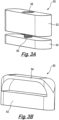
- the closure component is configured to close the bone graft material delivery opening, for example after filling of the graft material holding space with bone graft material. As described below, the closure component may be configured to pressurise bone graft material contained in the bone graft material holding space.
- the core component engages with each of the superior and inferior components to resist ejection of bone graft material from the bone graft material holding space through the side boundary when the bone graft material delivery opening is closed by the closure component and while bone graft material is ejected through the at least one bone graft conveying aperture. Pressurisation of bone graft material in the bone graft material holding space causes ejection of bone graft material through the at least one bone graft conveying aperture.
- Engagement of the core component with each of the superior and inferior components presents resistance to ejection of bone graft material through the side boundary and, more specifically, through the side boundary between the core component and the superior component and between the core component and the inferior component.
- Presenting resistance to ejection of bone graft material in this fashion may maintain pressure within the bone graft material holding space so that bone graft material is ejected through the at least one bone graft conveying aperture.
- Engagement of the core component with each of the superior and inferior components may be imperfect, for example such that there is no fluid tight seal, whereby air or bone graft material is lost through the side boundary. Nevertheless, engagement of the core component with each of the superior and inferior components present sufficient resistance that bone graft material is ejected preferentially through the at least one bone graft conveying aperture.
- a superior bone graft conveying aperture may be defined in the superior component top surface and an inferior bone graft conveying aperture may be defined in the inferior component bottom surface.
- Bone graft material may therefore be ejected by way of a holding space opening in each of the core component top and bottom surfaces through the superior bone graft conveying aperture and the inferior bone graft conveying aperture.
- a superior bone graft conveying aperture may be defined in the superior component top surface and the inferior component bottom surface may lack an inferior bone graft conveying aperture.
- Bone graft material may therefore be ejected by way of the holding space opening in the core component top surface and through the superior component only of the superior and inferior components.
- a gap between a vertebra and the inferior component may be filled before and/or after insertion of the intervertebral fusion device with gravity being relied on to maintain bone graft material in this space.
- Resistance to ejection of bone graft material through the side boundary may be by way of the core component contacting each of the superior and inferior components.
- the core component may contact each of the superior and inferior components around the bone graft holding space. Contact may therefore surround the bone graft receiving space at a respective end of the bone graft receiving space. Contact may thus surround each holding space opening.
- Contact between the core component and each of the superior and inferior components may not be continuous and absolute around the bone graft holding space. This is because sufficient resistance to ejection through the side boundary may be required for preferential ejection of bone graft material through the at least one bone graft conveying aperture. There may therefore be small gaps in contact between the core component and the superior and inferior components.
- bone graft material may comprise ceramic or bone chips carried in a binder material. Resistance to ejection through the side boundary may be achieved where gaps in contact between the core component and the superior and inferior components are no larger than the size of the ceramic or bone chips.
- resistance to ejection of bone graft material through the side boundary may be achieved by sufficient adjacency of the core component to each of the superior and inferior components having regard to viscosity of the bone graft material being used.
- the core component may be less adjacent to at least one of the superior and inferior components.
- the bone graft material may have a dynamic viscosity of no more than 250,000 centipoise (cP). Where the bone graft material is less viscous, such that it is of the consistency of saline, greater adjacency of core component and at least one of the superior and inferior components may be needed to maintain pressure of bone graft material such that it is preferentially ejected through the at least one bone graft conveying aperture.
- the bone graft material may have a dynamic viscosity of at least 0.9 centipoise (cP).
- the side boundary may define a liquid tight barrier against passage of bone graft material.
- the core component may have a core component superior profile, which surrounds the holding space opening, and the superior component may have a superior component profile, the core component superior profile abutting against the superior component profile.
- the core component superior profile may be substantially planar and the superior component profile may be substantially planar.
- the core component superior profile may be defined at an edge of a wall of the core component. The edge of the wall may be substantially planar.
- the wall of the core component may surround and thereby define the bone graft holding space. Furthermore, and where the core component has two holding space openings, an inside surface of the wall may define the bone graft holding space at least in part along the bone graft holding space between the holding space openings.
- the core component may have a core component inferior profile, which surrounds the holding space opening, and the inferior component may have an inferior component profile, the core component inferior profile abutting against the inferior component profile.
- the core component inferior profile may be substantially planar and the inferior component profile may be substantially planar.
- the core component inferior profile may be defined at an edge of a wall of the core component. The edge of the wall may be substantially planar.
- the wall of the core component may surround the bone graft holding space. Furthermore, an inside surface of the wall may define the bone graft holding space at least in part along the bone graft holding space between the holding space openings.
- the wall of the core component defining the core component inferior profile may be the same wall defining the core component superior profile.
- the bone graft material holding space may be defined by an enclosing perimeter wall.
- the bone graft material delivery opening may extend through the perimeter wall from outside the core component to the bone graft material holding space.
- the bone graft material holding space as defined by the perimeter wall may be generally rectangular when viewed from one of the holding space openings.
- a length and a width of the bone graft material holding space may be substantially the same as one progresses from the core component top surface to the core component bottom surface.
- the enclosing perimeter wall may extend between the holding space opening at the core component top surface and the holding space opening at the core component bottom surface.
- a holding space opening may be coterminous with a bone graft material conveying aperture.
- the holding space opening at the core component top surface may be coterminous with the superior bone graft material conveying aperture and the holding space opening at the core component bottom surface may be coterminous with the inferior bone graft material conveying aperture.
- the superior and inferior bone graft material conveying apertures may be of corresponding extent to the bone graft material holding space.
- the superior bone graft material conveying aperture may extend through the superior component whereby the superior bone graft material conveying aperture is open at each of the superior component top surface and a superior component bottom surface of the superior component.
- the inferior component may be similarly formed.
- the inferior bone graft material conveying aperture may therefore extend through the inferior component whereby the inferior bone graft material conveying aperture is open at each of the inferior component bottom surface and an inferior component top surface of the inferior component.
- the core component may have the form of a wedge and more specifically a frustum of a wedge.
- the core component and the inferior and superior components may be configured for insertion of the core component to be led by the thinner edge of the thinner and thicker edges of the core component.
- An inclination of the inferior and superior components relative to each other may thus be determined by way of the core component further to a separation between the inferior and superior components.
- Extent of inclination of the inferior and superior components may be determined by selection from a plurality of core components having core component top and bottom surfaces different relative inclinations. Nevertheless, the core component engages with each of the superior and inferior components to resist ejection of bone graft material from the bone graft material holding space through the side boundary when the bone graft material delivery opening is closed by the closure component.
- the core component may define plural bone graft material delivery openings.
- the plural bone graft material delivery openings may be closed by the closure component.
- each of the plural bone graft material delivery openings may be closed by a respective closure component.
- the bone graft material delivery opening may be at least 50% of a width of the core component. Alternatively or in addition, the bone graft material delivery opening may be at least 50% of a height of the core component. An area of the bone graft material delivery opening may be at least 60% of an area of an anterior aspect of the core component. Such a large bone graft material delivery opening may provide for ease of introduction of bone graft material to the bone graft material holding space.
- the closure component may have a protrusion which is shaped to be received in the bone graft material delivery opening.
- the protrusion may be a snug fit in the bone graft material delivery opening and more specifically a snap fit in the bone graft material delivery opening.
- the closure component may further have a base member from which the protrusion extends. The base member may abut against an outside surface of the core component when the protrusion is received in the bone graft material delivery opening.
- bone graft material is ejected through at least one of the inferior and superior components from the bone graft material holding space.
- the pressure of bone graft material remaining in the bone graft material holding space may decrease as bone graft material is ejected.
- the core component may be configured to increase the pressure of bone graft material remaining in the bone graft material holding space by reducing an effective volume of the bone graft material holding space.
- the closure component may be configured to move the protrusion further into the bone graft material delivery opening to thereby reduce the volume.
- the closure component may be user operable to move the protrusion further into the bone graft material delivery opening.
- the protrusion may, for example, be moved on a screw thread which is rotated by the user. The user may thus increase the pressure when he or she notices a drop in the rate of ejection of bone graft material.
- the protrusion may be self-regulating.
- the core component may exert a bias and more specifically a spring bias on the protrusion that urges the protrusion further into the bone graft material delivery opening.
- the protrusion itself may be configured to exert a spring bias.
- the protrusion may comprise a resilient portion of resilient material which deflects upon initial insertion of the protrusion to thereby store energy and in which deflection reduces under exertion of spring bias to thereby reduce the effective volume of the bone graft material holding space.
- the resilient portion may be a simply supported beam, i.e. a beam supported at or towards both ends.
- references herein to anterior or to anterior aspect are to the anterior aspect of the intervertebral fusion device itself and not to the anterior aspect of the patient.
- the anterior aspect of the intervertebral fusion device itself therefore means the aspect at which the core component is inserted between the superior and inferior components.
- references herein to posterior or to posterior aspect are to the posterior aspect of the intervertebral fusion device itself and not to the posterior aspect of the patient.
- the anterior and posterior aspects are oppositely directed.
- the intervertebral fusion device may be an anterior, anterior oblique, lateral or direct lateral intervertebral fusion device.
- the superior component, the inferior component and the core component are separate components. Furthermore, the superior component and the inferior component may be disconnected from each other in the absence of the core component. Having separate inferior and superior components and core component and more specifically disconnected inferior and superior components means that the components may be introduced to the intervertebral space more gently compared with known single piece intervertebral fusion devices which often need to be hammered into place. Such a less gentle insertion process may damage the vertebrae and perhaps also the intervertebral fusion device, may increase time required for the intervertebral fusion device to settle in the intervertebral space, and may result in trauma to vertebral bodies, adjacent soft tissues including neural structures.
- a device that is hammered into place is liable to create microfractures in the vertebrae which could lead to subsidence of the device into the host bone.
- having separate components and in particular a core component separate to the inferior and superior components allows for differences in dimensions of intervertebral spaces, differences in angle between the adjacent vertebrae that define the intervertebral space, and degree of spinal alignment and/or correction.
- Each of the superior component, the inferior component and the core component may be integrally formed. The superior component and the inferior component do not engage with each other, other than by way of the core component.
- Each of the inferior and superior components may have the form of a plate, albeit a plate having the structures described above thereon that provide for resistance to ejection of bone graft material through the side boundary, whereby it is thin relative to its length and width.
- At least one of the superior component top side and the inferior component bottom side may be shaped in the coronal or sagittal planes, for example domed, to enhance fit and contact with the adjacent vertebrae.
- At least one of the superior component top surface and the inferior component bottom surface may be configured to provide for fusion.
- the top or bottom side may comprise formations, such as protrusions, which, in use, engage with the bone of the vertebra.
- the top and/or bottom side may define apertures for passage of bone graft material therethrough from an interior of the intervertebral fusion device.
- the top or bottom side may have a coating thereon or impregnation therein. The coating or impregnation may comprise material that provides for bone adhesion and/or bone formation to encourage bone to grow up to and bond onto the intervertebral fusion device to thereby provide long term stable attachment.
- One or more known coatings may be used, such as porous mesh, tricalcium phosphate (TCP), hydroxyapatite (HA) or bone morphogenetic protein (BMP). At least one of the superior component top surface and the inferior component bottom surface may be configured to provide for cage fixation. Cage fixation may be useful to provide for stability until fusion has taken place.
- TCP tricalcium phosphate
- HA hydroxyapatite
- BMP bone morphogenetic protein
- At least one of the superior component, the core component, the inferior component and the closure component may be formed from a metal, such as titanium, or a metal alloy, such as stainless steel, Ti6AI4V, CoCr or nitinol. Nitinol may be useful in respect of cooperating parts of the superior component, the core component, the inferior component and the closure component. At least one of the superior component, the core component, the inferior component and the closure component may be formed from a plastics material and more specifically a thermoplastic polymer, such as PEEK or carbon reinforced PEEK.
- the core component may be formed in part by 3D printing whereby the core component has the form of a 3D lattice. The aforementioned materials may be used to form the core component by way of 3D printing.
- the intervertebral fusion device When assembled, the intervertebral fusion device may have a range of length by width from 20 mm by 15 mm to 65 mm by 50 mm. Where there is an oblique intervertebral fusion device, the range of length by width may be from 20 mm by 15 mm to 40 mm by 35 mm. Where there is an anterior intervertebral fusion device, the range of length by width may be from 20 mm by 20 mm to 50 mm by 50 mm. Where there is a lateral intervertebral fusion device, the range of length by width may be from 40 mm by 18 mm to 65 mm by 40 mm. A height of the intervertebral fusion device may be 5 mm to 15 mm at the posterior aspect.
- Figure 1A shows an exploded perspective view of an intervertebral fusion device 10 according to an embodiment of the invention when viewed from above, the anterior aspect and one side and Figure 1B shows an exploded perspective view of the same intervertebral fusion device 10 from below, the anterior aspect and the same side.
- the intervertebral fusion device 10 is also shown in Figure 2 when assembled.
- the intervertebral fusion device 10 comprises a superior component 12, an inferior component 14, a core component 16 and a closure component (not shown in Figures 1A, 1B and 2 ).
- the closure component is described below with reference to Figures 3A and 3B .
- the superior component 12 has a superior component top surface 18 which, in use, abuts against a first vertebra and the inferior component 14 has an inferior component bottom surface 20 which, in use, abuts against a second vertebra adjacent the first vertebra when the superior and inferior components are placed in the intervertebral space between the first and second vertebrae.
- the core component 16 is inserted between the thus installed superior and inferior components 12, 14 to thereby determine a separation and angle between the superior and inferior components.
- FIG. 1A and 1B opposing sides of the superior and inferior components 12, 14 define profiles and the top and the bottom of the core component 16 define profiles.
- the profiles defined on the top of the core component 16 inter-engage with the profiles defined in the adjacent side of the superior component 12 and the profiles defined on the bottom of the core component 16 inter-engage with the profiles defined in the adjacent side of the inferior component 14 to draw the superior and inferior components tightly to the core component as the core component is inserted.
- Figure 2 shows the intervertebral fusion device 10 when the core component 16 is fully inserted between the superior and inferior components 12, 14.
- a side boundary 22 of the intervertebral fusion device 10, which extends between the superior component top surface 18 and the inferior component bottom surface 20 and which defines a perimeter of the intervertebral fusion device, is defined by the superior and inferior components 12, 14 and the core component 16 when the core component is fully received between the superior and inferior components as shown in Figure 2 .
- the core component 16 defines a bone graft receiving space 24 of generally rectangular cross-section.
- the bone graft receiving space 24 extends through the core component between a first holding space opening at a top surface of the core component and a second holding space opening at a bottom surface of the core component.
- a wide bone graft material delivery opening 26 extends from an exterior side of the core component and opens into the bone graft receiving space 24.
- the bone graft material delivery opening 26 is closed by a closure component.
- the superior component 12 defines a superior bone graft conveying aperture 28 in the superior component top surface 18.
- the superior bone graft conveying aperture 28 is of substantially the same cross-sectional dimensions as the bone graft receiving space 24.
- the inferior component 14 defines an inferior bone graft conveying aperture 30 in the inferior component bottom surface 20.
- the inferior bone graft conveying aperture 30 is of substantially the same cross-sectional dimensions as the bone graft receiving space 24.
- the core component has a core component superior profile 32, which surrounds the first holding space opening, and a core component inferior profile 34, which surrounds the first holding space opening.
- Each edge of the core component superior profile 32 and the core component inferior profile 34 is planar.
- the core component and the superior and inferior components are thus configured to present resistance to ejection of bone graft material from the bone graft receiving space 24 between the core component and each of the superior and inferior components through the side boundary 22 of the intervertebral fusion device 10.
- bone graft material in the bone graft receiving space 24 is pressurised and when the bone graft material delivery opening 26 is closed, bone graft material is preferentially ejected from the bone graft receiving space through the superior and inferior bone graft conveying apertures 28, 30.
- FIG. 3A A view of a first embodiment 50 of closure component of the intervertebral fusion device is shown in Figure 3A .
- the closure component 50 is inserted into the bone graft material delivery opening 26.
- the closure component 50 is a tight fit in the bone graft material delivery opening 26 whereby bone graft material in the core component may be pressurised to sufficient extent without the closure component being ejected.
- the closure component 50 comprises a base member 52 and a movable member 54.
- the movable member 54 is received first of the base member and the movable member when the closure component is inserted into the bone graft material delivery opening.
- the base member 52 and the movable member 54 are mechanically coupled by a threaded bolt 56 which is seated in the base member.
- the side of the base member 52 facing away from the movable member 54 supports a head 58 of the threaded bolt 56.
- the user mechanically engages with the head 58 of the threaded bolt, such as with a tool, and rotates the threaded bolt in the base member 52.
- Rotation of the threaded bolt moves the movable member 54 towards or away from the base member 52 depending on direction of rotation by virtue of cooperation of the thread of the threaded bolt with a thread defined by the movable member.
- the user rotates the threaded bolt 56 to advance the movable member 54 further towards the bone graft receiving space and away from the base member 52. Pressure in the bone graft receiving space 24 is thus increased to thereby increase the rate of ejection of bone graft material from the bone graft receiving space.
- FIG. 3B A view of a second embodiment 60 of closure component of the intervertebral fusion device is shown in Figure 3B .
- the second embodiment 60 of closure component operates on a self-regulating basis in contrast to the manually operable first embodiment 50 of closure component.
- the second embodiment 60 of closure component comprises a base member 62 and a simply supported sprung beam 64 which is supported on an end of the base member.
- the second embodiment 60 of closure component is inserted with the sprung beam 64 foremost into the bone graft material delivery opening 26.
- the sprung beam 64 bows towards the base member 62 and thereby stores energy.
- the spring bias exerted by the sprung beam 64 into the bone graft receiving space 24 compensates for loss of pressure from the bone graft receiving space as bone graft material is ejected.
- the bone graft material held in the bone graft material holding space or injected into the bone graft material holding space has one of three forms.
- the bone graft material consists of bone or ceramic chips carried in a binder such that it has a paste or putty consistency, such as from Surgentec LLC, 7601 N Federal Highway, Suite 150A, Boca Raton, FL 33487, USA or from Pinnacle Spine Group, 2921 Canton Street, Dallas, TX 75226, USA.
- the bone graft material consists of viscous fluid, such as from Zimmer Biomet Dental, 4555 Riverside Drive, Palm Beach Gardens, FL 33410, USA or from Dentsply Sirona, Susquehanna Commerce Center, 221 W.
- the bone graft material consists of bone or ceramic chips only, i.e. no carrier material present although typically mixed with bone marrow aspirate or blood, such as from Kleiner Device Labs, LLC, 999 Driver Way, Incline Village, NV 89451, USA.
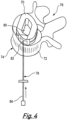
- Figure 4 shows another embodiment of intervertebral fusion device 70 in place above a lower vertebra 72.
- the lower vertebra 70 has an anatomical anterior aspect 74 and an anatomical posterior aspect 76.
- the adjacent upper vertebra is not shown in Figure 4 .
- the embodiment of Figure 4 is an oblique lateral interbody fusion device. The shape of the embodiment of Figure 4 is therefore different such that the anterior aspect of the device is presented at an angle to a line between the anterior and posterior anatomical aspects.
- the embodiment of Figure 4 has the same configuration as the embodiment 10 of Figures 1A to 3 such that the core component engages with each of the superior and inferior components to resist ejection of bone graft material from the bone graft material holding space through the side boundary when the bone graft material delivery opening is closed by the closure component and while bone graft material is ejected through the inferior and the superior bone graft conveying apertures.
- a plunger device 78 is used to inject bone graft material into the bone graft material holding space 80.
- a distal end 82 of the plunger device 78 is inserted into the bone graft material delivery opening and a plunger 84 of the plunger device 78 is depressed to inject bone graft material into the bone graft material holding space 80 from the plunger device.
- the distal end 82 of the plunger device is withdrawn from the bone graft material delivery opening and the bone graft material delivery opening is closed with a closure component, such as of the form shown in Figure 3A or 3B .
- the plunger device 78 is used to inject bone graft material of the second form described above. If the bone graft material of the first form is of relatively low viscosity, the plunger device 78 can be used for injection of the bone graft material. Alternatively, bone graft material of the first form is packed into the bone graft material holding space by way of the bone graft material delivery opening. As mentioned above, bone graft material can be placed in the bone graft material holding space before the intervertebral fusion device is placed in assembled form in the intervertebral space, subject to the bone graft material being sufficiently viscous.
- bone graft material of the third form is introduced into the intervertebral fusion device when in situ by way of the like of a funnel placed in the bone graft material delivery opening.
- the thus introduced bone graft material is then packed tightly with a tamp. Irrespective of the form of the bone graft material and whether the bone graft material is placed in the bone graft material holding space before installation or is injected or packed after installation, engagement of the core component with each of the superior and inferior components resists ejection of the thus held bone graft material through the side boundary 22.
Landscapes
- Health & Medical Sciences (AREA)
- Engineering & Computer Science (AREA)
- Biomedical Technology (AREA)
- Orthopedic Medicine & Surgery (AREA)
- Transplantation (AREA)
- Heart & Thoracic Surgery (AREA)
- Oral & Maxillofacial Surgery (AREA)
- Cardiology (AREA)
- Vascular Medicine (AREA)
- Life Sciences & Earth Sciences (AREA)
- Animal Behavior & Ethology (AREA)
- General Health & Medical Sciences (AREA)
- Public Health (AREA)
- Veterinary Medicine (AREA)
- Neurology (AREA)
- Physical Education & Sports Medicine (AREA)
- Prostheses (AREA)
Claims (15)
- Eine Zwischenwirbelfusionsvorrichtung (10, 70), die Folgendes beinhaltet:eine obere Komponente (12), die dazu ausgelegt ist, in einem Zwischenwirbelraum zwischen dem ersten und zweiten Wirbel aufgenommen zu werden, wodurch eine obere Komponentenoberfläche (18) der oberen Komponente gegen den ersten Wirbel stößt;eine untere Komponente (14), die dazu ausgelegt ist, in dem Zwischenwirbelraum aufgenommen zu werden, wodurch eine untere Komponentenunterfläche (20) der unteren Komponente gegen den zweiten Wirbel (70) stößt, wobei eine Knochentransplantat-Beförderungsöffnung (28, 30) in mindestens einer von der oberen Komponentenoberfläche und der unteren Komponentenunterfläche definiert ist;eine Kernkomponente (16) mit einer Kernkomponentenoberfläche, einer Kernkomponentenunterfläche und einer sich dazwischen erstreckenden Kernkomponentenseite, wobei die Kernkomponente (16) dazu ausgelegt ist, zwischen der oberen und unteren Komponente (12, 14) aufgenommen zu werden, um eine Trennung zwischen diesen zu bestimmen, wobei eine seitliche Grenzfläche (22) der Zwischenwirbelfusionsvorrichtung, die sich zwischen der oberen Komponentenoberfläche (18) und der unteren Komponentenunterfläche (20) erstreckt und die einen Umfang der Zwischenwirbelfusionsvorrichtung definiert, durch die obere und untere Komponente (12, 14) und die Kernkomponente (16) definiert wird, wenn die Kernkomponente zwischen der oberen und unteren Komponente aufgenommen wird; undeine Verschlusskomponente (50, 60), wobei:die Kernkomponente (16) einen Knochentransplantatmaterial-Halteraum (24, 80) definiert, der, außer an mindestens einer von der Kernkomponentenober- und - unterfläche und einer Knochentransplantatmaterial-Zuführöffnung (26) umschlossen ist, wobei eine Halteraumöffnung in mindestens einer von der Kernkomponentenober- und -unterfläche eine Fluidverbindung zwischen dem Knochentransplantatmaterial-Halteraum und der mindestens einen Knochentransplantat-Beförderungsöffnung (28, 30) bereitstellt, wenn die Kernkomponente (16) zwischen der oberen und unteren Komponente (12, 14) aufgenommen wird;die Knochentransplantatmaterial-Zuführöffnung (26) sich durch die Kernkomponentenseite von außerhalb der seitlichen Grenzfläche (22) bis zu dem Knochentransplantatmaterial-Halteraum (24, 80) erstreckt, wobei die Verschlusskomponente (50, 60) dazu ausgelegt ist, die Knochentransplantatmaterial-Zuführöffnung (26) zu verschließen;die Kernkomponente (16) in Eingriff mit jeder von der oberen und unteren Komponente (12, 14) steht, um einem Ausstoßen von Knochentransplantatmaterial aus dem Knochentransplantatmaterial-Halteraum durch die seitliche Grenzfläche (22) zu widerstehen, wenn die Knochentransplantatmaterial-Zuführöffnung (26) durch die Verschlusskomponente (50, 60) verschlossen wird und während das Knochentransplantatmaterial durch die mindestens eine Knochentransplantat-Beförderungsöffnung (28, 30) ausgestoßen wird; unddie obere Komponente (12), die untere Komponente (14) und die Kernkomponente (16) separate Komponenten sind, wobei die obere Komponente und die untere Komponente außer über die Kernkomponente nicht miteinander in Eingriff stehen,wobei die Zwischenwirbelfusionsvorrichtung (10, 70) ein Zwischenwirbelfusionsimplantat ist.
- Zwischenwirbelfusionsvorrichtung (10, 70) gemäß Anspruch 1, wobei eine obere Knochentransplantat-Beförderungsöffnung (28) in der oberen Komponentenoberfläche (18) definiert ist und eine untere Knochentransplantat-Beförderungsöffnung (30) in der unteren Komponentenunterfläche (20) definiert ist, wodurch Knochentransplantatmaterial über die Halteraumöffnung in jeder von der Kernkomponentenober- und -unterfläche durch die obere Knochentransplantat-Beförderungsöffnung und durch die untere Knochentransplantat-Beförderungsöffnung ausgestoßen werden kann.
- Zwischenwirbelfusionsvorrichtung (10, 70) gemäß Anspruch 1 oder 2, wobei die Kernkomponente (16) mit jeder von der oberen und unteren Komponente (12, 14) in Kontakt gebracht wird, um Widerstand gegen ein Ausstoßen von Knochentransplantatmaterial durch die seitliche Grenzfläche (22) zu bieten, und wobei die Kernkomponente (16) mit jeder von der oberen und unteren Komponente (12, 14) um den Knochentransplantatmaterial-Halteraum (24, 80) herum in Kontakt gebracht wird, wodurch jeder derartige Kontakt den Knochentransplantatmaterial-Halteraum an einem jeweiligen Ende des Knochentransplantatmaterial-Halteraums umgibt.
- Zwischenwirbelfusionsvorrichtung (10, 70) gemäß Anspruch 3, wobei der Kontakt zwischen der Kernkomponente (16) und jeder von der oberen und unteren Komponente (12, 14) nicht fortlaufend um den Knochentransplantatmaterial-Halteraum (24, 80) ist, aber ausreichend ist, um Widerstand gegen ein Ausstoßen von Knochentransplantatmaterial durch die seitliche Grenzfläche (22) zu bieten, wodurch Knochentransplantatmaterial bevorzugt durch die mindestens eine Knochentransplantat-Beförderungsöffnung (28, 30), ausgestoßen wird, wobei die Zwischenwirbelfusionsvorrichtung (10, 70) ferner Knochentransplantatmaterial beinhaltet, wobei das Knochentransplantatmaterial mehrere in einem Bindemittelmaterial enthaltene Keramik- oder Knochenspäne beinhaltet, wobei es Lücken in dem Kontakt zwischen der Kernkomponente (16) und der oberen und unteren Komponente (12, 14) gibt, und wobei jede Lücke nicht größer als die Größe eines Keramik- oder Knochenspans ist.
- Zwischenwirbelfusionsvorrichtung (10, 70) gemäß Anspruch 1 oder 2, die ferner Knochentransplantatmaterial beinhaltet, wobei die Kernkomponente (16) an jede von der oberen und unteren Komponente (12, 14) um den Knochentransplantatmaterial-Halteraum (24, 80) herum angrenzt, wodurch der Knochentransplantatmaterial-Halteraum an einem jeweiligen Ende des Knochentransplantatmaterial-Halteraums umgeben ist, wobei die Kernkomponente nicht in Kontakt mit mindestens einer von der oberen und unteren Komponente an mindestens einem Ort ist, an dem die Kernkomponente an die obere Komponente oder die untere Komponente angrenzt, und wobei das Knochentransplantatmaterial eine dynamische Viskosität von mindestens 0,9 Centipoise (cP) aufweist, um somit Widerstand gegen ein Ausstoßen von Knochentransplantatmaterial durch die seitliche Grenzfläche (22) zu bieten.
- Zwischenwirbelfusionsvorrichtung (10, 70) gemäß einem der Ansprüche 1 bis 3, wobei die seitliche Grenzfläche (22) eine flüssigkeitsdichte Barriere gegen einen Durchtritt von Knochentransplantatmaterial definiert.
- Zwischenwirbelfusionsvorrichtung (10, 70) gemäß einem der vorhergehenden Ansprüche, wobei die Kernkomponente (16) ein oberes Kernkomponentenprofil (32) aufweist, das die Halteraumöffnung umgibt, und wobei die obere Komponente (12) ein oberes Komponentenprofil aufweist, wobei das obere Kernkomponentenprofil gegen das obere Komponentenprofil stößt und wobei das obere Kernkomponentenprofil im Wesentlichen planar ist und das obere Komponentenprofil im Wesentlichen planar ist.
- Zwischenwirbelfusionsvorrichtung (10, 70) gemäß Anspruch 7, wobei das obere Kernkomponentenprofil (32) an einem Rand einer Wand der Kernkomponente (16) definiert ist, wobei die Wand der Kernkomponente den Knochentransplantatmaterial-Halteraum (24, 80) umgibt und somit definiert, und wobei es eine Halteraumöffnung in jeder von der Kernkomponentenober- und -unterfläche gibt, wobei eine innere Oberfläche der Wand den Knochentransplantatmaterial-Halteraum zwischen den Halteraumöffnungen definiert.
- Zwischenwirbelfusionsvorrichtung (10, 70) gemäß einem der vorhergehenden Ansprüche, wobei die Kernkomponente ein unteres Kernkomponentenprofil (34) aufweist, das die Halteraumöffnung umgibt, und die untere Komponente (14) ein unteres Komponentenprofil aufweist, wobei das untere Kernkomponentenprofil gegen das untere Komponentenprofil stößt.
- Zwischenwirbelfusionsvorrichtung (10, 70) gemäß einem der vorhergehenden Ansprüche, wobei die obere Komponente (12) eine obere Knochentransplantatmaterial-Beförderungsöffnung (28) beinhaltet, die sich durch die obere Komponente erstreckt, wodurch die obere Knochentransplantatmaterial-Beförderungsöffnung an jeder von der oberen Komponentenoberfläche und einer oberen Komponentenunterfläche der oberen Komponente offen ist.
- Zwischenwirbelfusionsvorrichtung (10, 70) gemäß einem der vorhergehenden Ansprüche, wobei die untere Komponente (14) eine untere Knochentransplantatmaterial-Beförderungsöffnung (30) beinhaltet, die sich durch die untere Komponente erstreckt, wodurch die untere Knochentransplantatmaterial-Beförderungsöffnung an jeder von der unteren Komponentenunterfläche und einer unteren Komponentenoberfläche der unteren Komponente offen ist.
- Zwischenwirbelfusionsvorrichtung (10, 70) gemäß einem der vorhergehenden Ansprüche, wobei die Verschlusskomponente (50, 60) einen Vorsprung (52, 64) aufweist, der so geformt ist, dass er eng anliegend in die Knochentransplantatmaterial-Zuführöffnung hineinpasst.
- Zwischenwirbelfusionsvorrichtung (10, 70) gemäß Anspruch 12, wobei die Kernkomponente (50, 60) dazu ausgelegt ist, den Druck des Knochentransplantatmaterials, das in dem Knochentransplantatmaterial-Halteraum (24, 80) nach einem Ausstoßen von Knochentransplantatmaterial durch mindestens eine von der unteren und oberen Komponente (12, 14) noch verblieben ist, durch Reduzieren eines Nutzvolumens des Knochentransplantatmaterial-Halteraums zu erhöhen, wobei das Nutzvolumen reduziert wird, indem der Vorsprung (52, 64) weiter in die Knochentransplantatmaterial-Zuführöffnung (26) hineinbewegt wird.
- Zwischenwirbelfusionsvorrichtung (10, 70) gemäß Anspruch 13, wobei die Verschlusskomponente (50, 60) benutzerbedienbar ist, um den Vorsprung (52, 64) weiter in die Knochentransplantatmaterial-Zuführöffnung (26) hinein zu bewegen.
- Zwischenwirbelfusionsvorrichtung (10, 70) gemäß Anspruch 13 oder 14, wobei die Kernkomponente (50, 60) eine Federvorspannung auf den Vorsprung (52, 64) ausübt, um den Vorsprung weiter in die Knochentransplantatmaterial-Zuführöffnung (26) hinein zu drängen.
Applications Claiming Priority (2)
| Application Number | Priority Date | Filing Date | Title |
|---|---|---|---|
| GBGB1818850.8A GB201818850D0 (en) | 2018-11-19 | 2018-11-19 | Intervertebral devices |
| PCT/GB2019/053277 WO2020104792A1 (en) | 2018-11-19 | 2019-11-19 | Intervertebral devices |
Publications (3)
| Publication Number | Publication Date |
|---|---|
| EP3883504A1 EP3883504A1 (de) | 2021-09-29 |
| EP3883504B1 true EP3883504B1 (de) | 2024-12-25 |
| EP3883504C0 EP3883504C0 (de) | 2024-12-25 |
Family
ID=64739927
Family Applications (1)
| Application Number | Title | Priority Date | Filing Date |
|---|---|---|---|
| EP19820851.4A Active EP3883504B1 (de) | 2018-11-19 | 2019-11-19 | Zwischenwirbelimplantat |
Country Status (5)
| Country | Link |
|---|---|
| US (2) | US12090063B2 (de) |
| EP (1) | EP3883504B1 (de) |
| AU (1) | AU2019385750B2 (de) |
| GB (1) | GB201818850D0 (de) |
| WO (1) | WO2020104792A1 (de) |
Families Citing this family (6)
| Publication number | Priority date | Publication date | Assignee | Title |
|---|---|---|---|---|
| GB201902002D0 (en) * | 2019-02-13 | 2019-04-03 | Axis Spine Tech Ltd | Intervertebral devices |
| GB201910668D0 (en) | 2019-07-25 | 2019-09-11 | Axis Spine Tech Ltd | Assemblies for and methods of determing height and angle of an intervertebral device |
| GB201910640D0 (en) | 2019-07-25 | 2019-09-11 | Axis Spine Tech Ltd | Insertions instruments |
| GB201913778D0 (en) * | 2019-09-24 | 2019-11-06 | Axis Spine Tech Ltd | Intervertebral devices |
| WO2023285675A1 (en) | 2021-07-16 | 2023-01-19 | Blue Ocean Spine Gmbh | Adjustable intervertebral cage, associated instrument and manufacturing process therefor |
| US12453640B2 (en) | 2021-07-16 | 2025-10-28 | Blue Ocean Spine Gmbh | Adjustable spinal implants, associated instruments and methods |
Citations (7)
| Publication number | Priority date | Publication date | Assignee | Title |
|---|---|---|---|---|
| US6102950A (en) * | 1999-01-19 | 2000-08-15 | Vaccaro; Alex | Intervertebral body fusion device |
| US20070270957A1 (en) * | 2006-04-13 | 2007-11-22 | Sdgi Holdings, Inc. | Vertebral implants having predetermined angular correction and methods of use |
| US20080294260A1 (en) * | 2007-05-22 | 2008-11-27 | Wayne Gray | Spinal implant system and method |
| US20130085573A1 (en) * | 2011-10-04 | 2013-04-04 | Zimmer Spine, Inc. | Interbody vertebral spacer |
| US20130103153A1 (en) * | 2011-10-24 | 2013-04-25 | Warsaw Orthopedic, Inc. | Interbody implant system and methods of use |
| US20130158667A1 (en) * | 2011-11-17 | 2013-06-20 | Exactech, Inc. | Expandable interbody device system and method |
| US8545567B1 (en) * | 2008-11-14 | 2013-10-01 | David Krueger | Spinal fusion device |
Family Cites Families (30)
| Publication number | Priority date | Publication date | Assignee | Title |
|---|---|---|---|---|
| US6045579A (en) | 1997-05-01 | 2000-04-04 | Spinal Concepts, Inc. | Adjustable height fusion device |
| US6113637A (en) | 1998-10-22 | 2000-09-05 | Sofamor Danek Holdings, Inc. | Artificial intervertebral joint permitting translational and rotational motion |
| US20050049707A1 (en) * | 2003-08-29 | 2005-03-03 | Ferree Bret A. | Cemented artificial disc replacements |
| US6468311B2 (en) * | 2001-01-22 | 2002-10-22 | Sdgi Holdings, Inc. | Modular interbody fusion implant |
| DE10116412C1 (de) | 2001-04-02 | 2003-01-16 | Ulrich Gmbh & Co Kg | Implantat zum Einsetzen zwischen Wirbelkörper der Wirbelsäule |
| US7214243B2 (en) | 2002-10-21 | 2007-05-08 | 3Hbfm, Llc | Intervertebral disk prosthesis |
| US8388686B2 (en) | 2002-12-17 | 2013-03-05 | Max Aebi | Intervertebral implant with tiltable joint parts |
| CA2573340A1 (en) | 2004-07-09 | 2006-02-16 | Pioneer Laboratories, Inc. | Skeletal reconstruction device |
| SE528708C8 (sv) * | 2005-06-01 | 2007-03-13 | Ortoviva Ab | Anordning vid diskimplantat |
| US9526628B2 (en) * | 2008-11-14 | 2016-12-27 | David Krueger | Spinal fusion device |
| US8308804B2 (en) | 2008-11-14 | 2012-11-13 | David Krueger | Spinal fusion device |
| US20110153020A1 (en) | 2009-12-17 | 2011-06-23 | Custom Spine, Inc. | Anterior Lumbar Interbody |
| US8465547B2 (en) * | 2010-01-27 | 2013-06-18 | Warsaw Orthopedic, Inc. | Modular interbody devices and methods of use |
| US9592063B2 (en) | 2010-06-24 | 2017-03-14 | DePuy Synthes Products, Inc. | Universal trial for lateral cages |
| US8936599B2 (en) | 2011-11-02 | 2015-01-20 | Tenzin Llc | Translational instrumentation for spondylolisthesis and scoliosis reduction |
| WO2013184946A1 (en) * | 2012-06-06 | 2013-12-12 | Medivest, Llc | Expandable tissue spacer implant and method of use |
| US9498349B2 (en) | 2012-10-09 | 2016-11-22 | Titan Spine, Llc | Expandable spinal implant with expansion wedge and anchor |
| US8663332B1 (en) | 2012-12-13 | 2014-03-04 | Ouroboros Medical, Inc. | Bone graft distribution system |
| US9585765B2 (en) | 2013-02-14 | 2017-03-07 | Globus Medical, Inc | Devices and methods for correcting vertebral misalignment |
| US8900312B2 (en) * | 2013-03-12 | 2014-12-02 | Spine Wave, Inc. | Expandable interbody fusion device with graft chambers |
| US8828019B1 (en) * | 2013-03-13 | 2014-09-09 | Spine Wave, Inc. | Inserter for expanding an expandable interbody fusion device |
| US9801734B1 (en) | 2013-08-09 | 2017-10-31 | Nuvasive, Inc. | Lordotic expandable interbody implant |
| US9402739B2 (en) | 2014-02-07 | 2016-08-02 | Globus Medical, Inc. | Variable lordosis spacer and related methods of use |
| FR3020756B1 (fr) * | 2014-05-06 | 2022-03-11 | Ldr Medical | Implant vertebral, dispositif de fixation vertebrale d'implant et instrumentation d'implantation |
| US9632020B2 (en) | 2014-10-22 | 2017-04-25 | The Boeing Company | Non-linear optical ellipsometry for surface monitoring and characterization |
| US10363142B2 (en) | 2014-12-11 | 2019-07-30 | K2M, Inc. | Expandable spinal implants |
| US9060876B1 (en) | 2015-01-20 | 2015-06-23 | Ouroboros Medical, Inc. | Stabilized intervertebral scaffolding systems |
| US11020241B2 (en) * | 2016-02-23 | 2021-06-01 | Life Spine, Inc. | Expandable lateral spine cage with reverse dovetail configuration |
| US10052215B2 (en) | 2016-06-29 | 2018-08-21 | Globus Medical, Inc. | Expandable fusion device and method of installation thereof |
| US9883953B1 (en) | 2016-09-21 | 2018-02-06 | Integrity Implants Inc. | Stabilized laterovertically-expanding fusion cage systems with tensioner |
-
2018
- 2018-11-19 GB GBGB1818850.8A patent/GB201818850D0/en not_active Ceased
-
2019
- 2019-11-19 EP EP19820851.4A patent/EP3883504B1/de active Active
- 2019-11-19 AU AU2019385750A patent/AU2019385750B2/en active Active
- 2019-11-19 WO PCT/GB2019/053277 patent/WO2020104792A1/en not_active Ceased
- 2019-11-19 US US17/294,684 patent/US12090063B2/en active Active
-
2024
- 2024-09-16 US US18/885,748 patent/US20250152378A1/en active Pending
Patent Citations (7)
| Publication number | Priority date | Publication date | Assignee | Title |
|---|---|---|---|---|
| US6102950A (en) * | 1999-01-19 | 2000-08-15 | Vaccaro; Alex | Intervertebral body fusion device |
| US20070270957A1 (en) * | 2006-04-13 | 2007-11-22 | Sdgi Holdings, Inc. | Vertebral implants having predetermined angular correction and methods of use |
| US20080294260A1 (en) * | 2007-05-22 | 2008-11-27 | Wayne Gray | Spinal implant system and method |
| US8545567B1 (en) * | 2008-11-14 | 2013-10-01 | David Krueger | Spinal fusion device |
| US20130085573A1 (en) * | 2011-10-04 | 2013-04-04 | Zimmer Spine, Inc. | Interbody vertebral spacer |
| US20130103153A1 (en) * | 2011-10-24 | 2013-04-25 | Warsaw Orthopedic, Inc. | Interbody implant system and methods of use |
| US20130158667A1 (en) * | 2011-11-17 | 2013-06-20 | Exactech, Inc. | Expandable interbody device system and method |
Also Published As
| Publication number | Publication date |
|---|---|
| US12090063B2 (en) | 2024-09-17 |
| GB201818850D0 (en) | 2019-01-02 |
| US20220015921A1 (en) | 2022-01-20 |
| WO2020104792A1 (en) | 2020-05-28 |
| AU2019385750A1 (en) | 2021-06-24 |
| AU2019385750B2 (en) | 2025-09-04 |
| EP3883504A1 (de) | 2021-09-29 |
| EP3883504C0 (de) | 2024-12-25 |
| US20250152378A1 (en) | 2025-05-15 |
Similar Documents
| Publication | Publication Date | Title |
|---|---|---|
| EP3883504B1 (de) | Zwischenwirbelimplantat | |
| US11872139B2 (en) | Enhanced cage insertion assembly | |
| US12023256B2 (en) | Modular plate and cage elements and related methods | |
| US12257158B2 (en) | Interbody fusion cages | |
| EP1437105B1 (de) | Zwischenwirbelfusionsvorrichtung | |
| EP2967904B1 (de) | Modulares, anpassbares wirbelsäulenstabilisierungssystem | |
| US8734521B2 (en) | Asymmetric disc distracting cage | |
| US9241810B1 (en) | Fusion device and associated methods | |
| US12127952B2 (en) | Intervertebral devices | |
| EP1477190A1 (de) | Poröser Block bestehend aus metallischen Kugeln zum Knocheneinwuchs | |
| WO2024009066A1 (en) | Intervertebral devices |
Legal Events
| Date | Code | Title | Description |
|---|---|---|---|
| STAA | Information on the status of an ep patent application or granted ep patent |
Free format text: STATUS: UNKNOWN |
|
| STAA | Information on the status of an ep patent application or granted ep patent |
Free format text: STATUS: THE INTERNATIONAL PUBLICATION HAS BEEN MADE |
|
| PUAI | Public reference made under article 153(3) epc to a published international application that has entered the european phase |
Free format text: ORIGINAL CODE: 0009012 |
|
| STAA | Information on the status of an ep patent application or granted ep patent |
Free format text: STATUS: REQUEST FOR EXAMINATION WAS MADE |
|
| 17P | Request for examination filed |
Effective date: 20210610 |
|
| AK | Designated contracting states |
Kind code of ref document: A1 Designated state(s): AL AT BE BG CH CY CZ DE DK EE ES FI FR GB GR HR HU IE IS IT LI LT LU LV MC MK MT NL NO PL PT RO RS SE SI SK SM TR |
|
| DAV | Request for validation of the european patent (deleted) | ||
| DAX | Request for extension of the european patent (deleted) | ||
| GRAJ | Information related to disapproval of communication of intention to grant by the applicant or resumption of examination proceedings by the epo deleted |
Free format text: ORIGINAL CODE: EPIDOSDIGR1 |
|
| STAA | Information on the status of an ep patent application or granted ep patent |
Free format text: STATUS: GRANT OF PATENT IS INTENDED |
|
| GRAP | Despatch of communication of intention to grant a patent |
Free format text: ORIGINAL CODE: EPIDOSNIGR1 |
|
| INTG | Intention to grant announced |
Effective date: 20240716 |
|
| RIN1 | Information on inventor provided before grant (corrected) |
Inventor name: MCKENNA, PATRICK Inventor name: SUTCLIFFE, JOHN Inventor name: POWELL, DAVID Inventor name: SANDHAM, NICHOLAS Inventor name: ARCOS, JONATHAN Inventor name: REAH, CHRISTOPHER |
|
| GRAS | Grant fee paid |
Free format text: ORIGINAL CODE: EPIDOSNIGR3 |
|
| GRAA | (expected) grant |
Free format text: ORIGINAL CODE: 0009210 |
|
| STAA | Information on the status of an ep patent application or granted ep patent |
Free format text: STATUS: THE PATENT HAS BEEN GRANTED |
|
| RAP3 | Party data changed (applicant data changed or rights of an application transferred) |
Owner name: AXIS SPINE TECHNOLOGIES LTD |
|
| RIN1 | Information on inventor provided before grant (corrected) |
Inventor name: MCKENNA, PATRICK Inventor name: SUTCLIFFE, JOHN Inventor name: POWELL, DAVID Inventor name: SANDHAM, NICHOLAS Inventor name: ARCOS, JONATHAN Inventor name: REAH, CHRISTOPHER |
|
| AK | Designated contracting states |
Kind code of ref document: B1 Designated state(s): AL AT BE BG CH CY CZ DE DK EE ES FI FR GB GR HR HU IE IS IT LI LT LU LV MC MK MT NL NO PL PT RO RS SE SI SK SM TR |
|
| REG | Reference to a national code |
Ref country code: GB Ref legal event code: FG4D |
|
| REG | Reference to a national code |
Ref country code: CH Ref legal event code: EP |
|
| REG | Reference to a national code |
Ref country code: DE Ref legal event code: R096 Ref document number: 602019064031 Country of ref document: DE |
|
| REG | Reference to a national code |
Ref country code: IE Ref legal event code: FG4D |
|
| U01 | Request for unitary effect filed |
Effective date: 20250117 |
|
| U07 | Unitary effect registered |
Designated state(s): AT BE BG DE DK EE FI FR IT LT LU LV MT NL PT RO SE SI Effective date: 20250123 |
|
| PG25 | Lapsed in a contracting state [announced via postgrant information from national office to epo] |
Ref country code: HR Free format text: LAPSE BECAUSE OF FAILURE TO SUBMIT A TRANSLATION OF THE DESCRIPTION OR TO PAY THE FEE WITHIN THE PRESCRIBED TIME-LIMIT Effective date: 20241225 |
|
| PG25 | Lapsed in a contracting state [announced via postgrant information from national office to epo] |
Ref country code: NO Free format text: LAPSE BECAUSE OF FAILURE TO SUBMIT A TRANSLATION OF THE DESCRIPTION OR TO PAY THE FEE WITHIN THE PRESCRIBED TIME-LIMIT Effective date: 20250325 |
|
| PG25 | Lapsed in a contracting state [announced via postgrant information from national office to epo] |
Ref country code: GR Free format text: LAPSE BECAUSE OF FAILURE TO SUBMIT A TRANSLATION OF THE DESCRIPTION OR TO PAY THE FEE WITHIN THE PRESCRIBED TIME-LIMIT Effective date: 20250326 |
|
| PG25 | Lapsed in a contracting state [announced via postgrant information from national office to epo] |
Ref country code: RS Free format text: LAPSE BECAUSE OF FAILURE TO SUBMIT A TRANSLATION OF THE DESCRIPTION OR TO PAY THE FEE WITHIN THE PRESCRIBED TIME-LIMIT Effective date: 20250325 |
|
| PG25 | Lapsed in a contracting state [announced via postgrant information from national office to epo] |
Ref country code: SM Free format text: LAPSE BECAUSE OF FAILURE TO SUBMIT A TRANSLATION OF THE DESCRIPTION OR TO PAY THE FEE WITHIN THE PRESCRIBED TIME-LIMIT Effective date: 20241225 |
|
| PG25 | Lapsed in a contracting state [announced via postgrant information from national office to epo] |
Ref country code: PL Free format text: LAPSE BECAUSE OF FAILURE TO SUBMIT A TRANSLATION OF THE DESCRIPTION OR TO PAY THE FEE WITHIN THE PRESCRIBED TIME-LIMIT Effective date: 20241225 |
|
| PG25 | Lapsed in a contracting state [announced via postgrant information from national office to epo] |
Ref country code: ES Free format text: LAPSE BECAUSE OF FAILURE TO SUBMIT A TRANSLATION OF THE DESCRIPTION OR TO PAY THE FEE WITHIN THE PRESCRIBED TIME-LIMIT Effective date: 20241225 |
|
| PG25 | Lapsed in a contracting state [announced via postgrant information from national office to epo] |
Ref country code: IS Free format text: LAPSE BECAUSE OF FAILURE TO SUBMIT A TRANSLATION OF THE DESCRIPTION OR TO PAY THE FEE WITHIN THE PRESCRIBED TIME-LIMIT Effective date: 20250425 |
|
| PG25 | Lapsed in a contracting state [announced via postgrant information from national office to epo] |
Ref country code: SK Free format text: LAPSE BECAUSE OF FAILURE TO SUBMIT A TRANSLATION OF THE DESCRIPTION OR TO PAY THE FEE WITHIN THE PRESCRIBED TIME-LIMIT Effective date: 20241225 |
|
| PG25 | Lapsed in a contracting state [announced via postgrant information from national office to epo] |
Ref country code: CZ Free format text: LAPSE BECAUSE OF FAILURE TO SUBMIT A TRANSLATION OF THE DESCRIPTION OR TO PAY THE FEE WITHIN THE PRESCRIBED TIME-LIMIT Effective date: 20241225 |
|
| PLBE | No opposition filed within time limit |
Free format text: ORIGINAL CODE: 0009261 |
|
| STAA | Information on the status of an ep patent application or granted ep patent |
Free format text: STATUS: NO OPPOSITION FILED WITHIN TIME LIMIT |
|
| REG | Reference to a national code |
Ref country code: CH Ref legal event code: L10 Free format text: ST27 STATUS EVENT CODE: U-0-0-L10-L00 (AS PROVIDED BY THE NATIONAL OFFICE) Effective date: 20251105 |
|
| REG | Reference to a national code |
Ref country code: CH Ref legal event code: U11 Free format text: ST27 STATUS EVENT CODE: U-0-0-U10-U11 (AS PROVIDED BY THE NATIONAL OFFICE) Effective date: 20251201 |
|
| 26N | No opposition filed |
Effective date: 20250926 |