EP3883476B1 - Collimator control - Google Patents
Collimator control Download PDFInfo
- Publication number
- EP3883476B1 EP3883476B1 EP19813991.7A EP19813991A EP3883476B1 EP 3883476 B1 EP3883476 B1 EP 3883476B1 EP 19813991 A EP19813991 A EP 19813991A EP 3883476 B1 EP3883476 B1 EP 3883476B1
- Authority
- EP
- European Patent Office
- Prior art keywords
- collimator
- knobs
- shaft
- pair
- aperture
- Prior art date
- Legal status (The legal status is an assumption and is not a legal conclusion. Google has not performed a legal analysis and makes no representation as to the accuracy of the status listed.)
- Active
Links
Images




Classifications
-
- G—PHYSICS
- G21—NUCLEAR PHYSICS; NUCLEAR ENGINEERING
- G21K—HANDLING OF PARTICLES OR IONISING RADIATION NOT OTHERWISE PROVIDED FOR; IRRADIATION DEVICES; GAMMA RAY OR X-RAY MICROSCOPES
- G21K1/00—Arrangements for handling particles or ionising radiation, e.g. focusing or moderating
- G21K1/02—Arrangements for handling particles or ionising radiation, e.g. focusing or moderating using diaphragms, collimators
- G21K1/04—Arrangements for handling particles or ionising radiation, e.g. focusing or moderating using diaphragms, collimators using variable diaphragms, shutters, choppers
-
- A—HUMAN NECESSITIES
- A61—MEDICAL OR VETERINARY SCIENCE; HYGIENE
- A61B—DIAGNOSIS; SURGERY; IDENTIFICATION
- A61B6/00—Apparatus or devices for radiation diagnosis; Apparatus or devices for radiation diagnosis combined with radiation therapy equipment
- A61B6/46—Arrangements for interfacing with the operator or the patient
-
- A—HUMAN NECESSITIES
- A61—MEDICAL OR VETERINARY SCIENCE; HYGIENE
- A61B—DIAGNOSIS; SURGERY; IDENTIFICATION
- A61B6/00—Apparatus or devices for radiation diagnosis; Apparatus or devices for radiation diagnosis combined with radiation therapy equipment
- A61B6/06—Diaphragms
Definitions
- another pair of the control knobs attached to a common shaft, may be configured to simultaneously move another pair of collimator blades 120, 121, when either of the pair of control knobs is rotated.
- Manual rotation in one direction of either control knob of the pair may cause the collimator blades 120, 121, to move toward each other, thereby decreasing dimension a of the collimator aperture 122.
- Manual rotation in an opposite direction of either control knob of the pair may cause the collimator blades 120, 121, to move away from each other, thereby increasing dimension a of the collimator aperture 122.
Landscapes
- Engineering & Computer Science (AREA)
- Physics & Mathematics (AREA)
- Health & Medical Sciences (AREA)
- Life Sciences & Earth Sciences (AREA)
- High Energy & Nuclear Physics (AREA)
- Medical Informatics (AREA)
- General Engineering & Computer Science (AREA)
- Spectroscopy & Molecular Physics (AREA)
- Biomedical Technology (AREA)
- Surgery (AREA)
- Pathology (AREA)
- Radiology & Medical Imaging (AREA)
- Nuclear Medicine, Radiotherapy & Molecular Imaging (AREA)
- Heart & Thoracic Surgery (AREA)
- Molecular Biology (AREA)
- Optics & Photonics (AREA)
- Animal Behavior & Ethology (AREA)
- General Health & Medical Sciences (AREA)
- Public Health (AREA)
- Veterinary Medicine (AREA)
- Biophysics (AREA)
- Human Computer Interaction (AREA)
- Apparatus For Radiation Diagnosis (AREA)
- Radiation-Therapy Devices (AREA)
Description
- The subject matter disclosed herein relates to x-ray systems in medical imaging facilities. In particular, the present invention is directed to collimator aperture size control using knobs attached to a collimator as part of a tube head containing an x-ray source and the collimator.
- Reference is made to
JP 2009-018208 A - In accordance with the present invention, a collimator as set forth in Claim 1 is provided. Further embodiments of the invention are inter alia disclosed in the dependent claims.
- An adjustable collimator includes a pair of knobs configured to adjust an aperture size by manipulating one or both of the knobs. The knobs may be disposed at opposite ends of a first shaft. The knobs may be configured to each adjust a same dimension of the aperture or to each adjust a different dimension of the aperture. An advantage that may be realized in the practice of some disclosed embodiments of the adjustable collimator is easier manual adjustment of the aperture.
- In one embodiment, a collimator includes an adjustable aperture size and a pair of knobs configured to adjust the aperture size by manipulating one or both of the knobs. The knobs are each disposed at opposite ends of a shaft or rod and are configured to each adjust a different dimension of the adjustable aperture.
- The summary descriptions above are not meant to describe individual separate embodiments whose elements are not interchangeable. In fact, many of the elements described as related to a particular embodiment can be used together with, and possibly interchanged with, elements of other described embodiments. Many changes and modifications may be made within the scope of the a. The drawings below are intended to be drawn neither to any precise scale with respect to relative size, angular relationship, relative position, or timing relationship, nor to any combinational relationship with respect to interchangeability, substitution, or representation of a required implementation.
- This brief description of the invention is intended only to provide a brief overview of subject matter disclosed herein according to one or more illustrative embodiments, and does not serve as a guide to interpreting the claims or to define or limit the scope of the invention, which is defined only by the appended claims. This brief description is provided to introduce an illustrative selection of concepts in a simplified form that are further described below in the detailed description. This brief description is not intended to identify key features or essential features of the claimed subject matter, nor is it intended to be used as an aid in determining the scope of the claimed subject matter. The claimed subject matter is not limited to implementations that solve any or all disadvantages noted in the background.
- So that the manner in which the features of the invention can be understood, a detailed description of the invention may be had by reference to certain embodiments, some of which are illustrated in the accompanying drawings. It is to be noted, however, that the drawings illustrate only certain embodiments of this invention and are therefore not to be considered limiting of its scope, for the scope of the invention encompasses other equally effective embodiments. The drawings are not necessarily to scale, emphasis generally being placed upon illustrating the features of certain embodiments of the invention. In the drawings, like numerals are used to indicate like parts throughout the various views. Thus, for further understanding of the invention, reference can be made to the following detailed description, read in connection with the drawings in which:
-
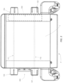
FIG. 1 is a front view of an exemplary collimator; -
FIG. 2 is a bottom view of the exemplary collimator ofFIG. 1 ; -
FIG. 3 is a top view of the exemplary collimator ofFIG. 1 ; -
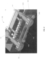
FIGS. 4 and5 show a cross section of an exemplary assembly for providing advantageous control knob functions; -
FIG. 6 is a front view of the exemplary assembly for providing advantageous control knob functions; and -
FIG. 7 shows an example mobile x-ray cart having a tube head utilizing the exemplary collimator having the exemplary assembly described herein. -
FIG. 1 shows a front side F of a collimator 100 which may be attached to an x-ray source (not shown) for collimating an x-ray beam generated by the x-ray source. The collimator 100 includes an aperture that may be adjusted in two dimensions using a pair ofcontrol knobs FIG. 1 , which emits an x-ray beam aimed downward through the bottom side B of the collimator 100 toward a subject to be radiographically imaged. The aperture inside the collimator 100 shapes the x-ray beam into a desired x-ray beam having adjustable width and length dimensions as the x-ray beam exits the collimator 100 on the bottom side B thereof. - In one embodiment, described herein, the
collimator knobs shaft 110 such that manually rotating one of theknobs shaft 110 to rotate and causes theother knob knobs shaft 110. -
FIG. 2 is a bottom view of the collimator 100 further illustrating a second pair ofcontrol knobs knobs FIG. 1 ) and a centrally positionedcollimator aperture 122. Each of thecontrol knobs second shaft 111. One pair of the control knobs, say, 101, 102, may be used to control one dimension of thecollimator aperture 122, either a length or width dimension a, b, thereof, and another pair of the control knobs, say, 103, 104, may be used to control the other one of the length and width dimensions a, b, ofcollimator aperture 122. In one embodiment, described herein, thecollimator knobs shaft 111 such that manually rotating one of theknobs shaft 111 to rotate and causes the other knob to rotate due do the fixed attachment of theknobs shaft 111. - In one embodiment, one pair of the control knobs, attached to a common shaft, may be configured to simultaneously move one pair of
collimator blades collimator blades collimator aperture 122. Manual rotation in an opposite direction of either control knob of the pair may cause thecollimator blades collimator aperture 122. Similarly, another pair of the control knobs, attached to a common shaft, may be configured to simultaneously move another pair ofcollimator blades 120, 121, when either of the pair of control knobs is rotated. Manual rotation in one direction of either control knob of the pair may cause thecollimator blades 120, 121, to move toward each other, thereby decreasing dimension a of thecollimator aperture 122. Manual rotation in an opposite direction of either control knob of the pair may cause thecollimator blades 120, 121, to move away from each other, thereby increasing dimension a of thecollimator aperture 122. In a typical example operation, a user may simultaneously graspknobs knobs collimator aperture 122. Similarly a user may simultaneously graspknobs knobs collimator aperture 122. Similarly, a user may also simultaneously graspknobs collimator aperture 122, as described. -
FIG. 3 is a top view of an embodiment of acollimator 300 illustrating control knobs 101-104 andshafts FIG. 3 ,control knob 101 may be fixably attached toshaft 110 andcontrol knob 103 may be fixably attached toshaft 111 as described herein above with respect toFIGS 1-2 . In the embodiment ofFIG. 3 ,control knob 102 is rotatably attached toshaft 110 andcontrol knob 104 is rotatably attached toshaft 111, whereby rotatingcontrol knob 102 does not causeshaft 110 to rotate, and rotatingcontrol knob 104 does not causeshaft 111 to rotate. Rather, viaassembly 330, described herein (FIGS. 4-6 ), which is disposed in thecollimator 300, rotatingcontrol knob 102 causesshaft 111 andcontrol knob 103 to rotate and is configured to adjust one dimension ofcollimator aperture 122, while rotatingcontrol knob 104 causesshaft 110 andcontrol knob 101 to rotate and is configured to adjust another dimension ofcollimator aperture 122. Similarly, rotatingcontrol knob 103 causesshaft 111 andcontrol knob 102 to rotate as well as adjusting one dimension ofcollimator aperture 122, and rotatingcontrol knob 101 causesshaft 110 andcontrol knob 104 to rotate as well as adjusting another dimension ofcollimator aperture 122. As described herein above, in the embodiment ofFIG. 3 each pair of control knobs, 101 & 104 and 102 & 103 rotate together to cause adjustment to thecollimator aperture 122 by moving a corresponding pair ofcollimator blades - In a typical example operation of the
collimator 300 embodiment ofFIG. 3 , a user may simultaneously graspknobs collimator 300, using one hand for each knob, to rotate bothknobs collimator aperture 122. Similarly a user may simultaneously grasp pairs ofknobs collimator aperture 122. Thus, a user is able to adjust both dimensions of thecollimator aperture 122 using knobs on either side (left/right) of thecollimator 300 or the knobs proximate to the front F of thecollimator 300. Theshafts FIGS. 1-3 in schematic form. Theshafts FIG. 5 ) etc., formed therein or attached thereto. -
FIG. 4 is a cross section view ofassembly 330 along a plane through theshafts assembly 330 which is configured to allow operation of thecollimator 300 as described above with reference to the embodiment ofFIG. 3 .Knobs shafts knob 102 is fixably attached to a first rigidlinear extension 151A using connector 160 and extension 161 (FIG. 6 ) which are fixably attached to controlknob 102, causing rigidlinear extension 151A to rotate about theshaft 110 whencontrol knob 102 is rotated. Rigidlinear extension 151A is attached to rigid rod or bar 152 using apivoting coupling 153a.Rigid rod 152 is attached to a second linear rigid extension 151B using another pivotingcoupling 153b. Linear rigid extension 151B is fixably attached toshaft 111. Thus, whencontrol knob 102 is manually rotated,shaft 110 is not thereby caused to rotate, andshaft 111 is caused to rotate via theassembly 330 comprising rigidlinear extensions 151A-151B,rigid rod 152 and two pivotingcouplings 153a,b. Knob 103 (not shown inFIG. 4 ) is fixably attached to an opposite end ofshaft 111 and rotates together withshaft 111. Similarly, whenknob 103 is rotated, theassembly 330 causesknob 102 to rotate. As described herein, such rotation ofcontrol knobs collimator aperture 122. -
FIG. 5 is a copy ofFIG. 4 , and will be used to illustrate another portion ofassembly 330 which is configured to allow operation of thecollimator 300 as described above with reference to the embodiment ofFIG. 3 .Control knob 104 is fixably attached to rigid linear extension 154B, causing it to rotate about theshaft 111 whencontrol knob 104 is rotated. Rigid linear extension 154B is attached to rigid rod or bar 155 using a pivotingcoupling 156b.Rigid rod 155 is attached to linearrigid extension 154A using another pivotingcoupling 156a. Linearrigid extension 154A is fixably attached toshaft 110. Thus, whencontrol knob 104 is manually rotated,shaft 111 is not thereby caused to rotate, andshaft 110 is caused to rotate via theassembly 330 comprising rigidlinear extensions 154A-154B,rigid rod 155 and two pivotingcouplings 156a,b. Knob 101 (not shown inFIG. 5 ) is fixably attached to an opposite end ofshaft 110 and rotates together withshaft 110. Similarly, whenknob 101 is rotated, theassembly 330 causesknob 104 to rotate. As described herein, such rotation ofcontrol knobs collimator aperture 122.Glide bushings 170 may be used to rotatably attach eachcontrol knob shaft assembly 330 to operate in a similar fashion. For example, drive belts + pulleys, linkages, or gears may be used. -
FIG. 6 shows another view, from a front side ofcollimator 300, of a portion of theassembly 330 which may be referenced for clarity in view of the description above describingFIGS. 4-5 . In the view ofFIG. 6 ,knob 104 is directly behindknob 102 and so is not visible. Rigidlinear extension 151A is fixably attached toknob 102 but not toshaft 110. Rigidlinear extension 151A freely rotates aboutshaft 110. Rigidlinear extension 154A is fixably attached toshaft 110, using setscrew 601, but not toknob 102. Complementary couplings are used similarly to attach similar components toknob 104, as described herein. -
FIG. 7 shows an exemplary mobile x-ray system 700 having a base 701, anadjustable control arm 702 rotatably attached to thebase 701, which control arm supports a tube head 703, which tube head includes anx-ray source 704 and acollimator 705, which collimator may include the embodiment of collimator 100 orcollimator 300 described herein. Thecollimators 100, 300, may also be used with non-mobile in-room x-ray systems. - This written description uses examples to disclose the invention, including the best mode, and also to enable any person skilled in the art to practice the invention, including making and using any devices or systems and performing any incorporated methods. The patentable scope of the invention is defined by the claims, and may include other examples that occur to those skilled in the art.
Claims (10)
- A collimator (100; 300; 705) comprising:an adjustable aperture (122) size; anda first pair of knobs (101, 102) configured to adjust the aperture (122) size by manipulating one or both of the first pair of knobs (101, 102);wherein the first pair of knobs (101, 102) are each attached to opposite ends of a first shaft (110), andwherein each of the first pair of knobs (101, 102) is configured to adjust a different dimension of the adjustable aperture (122).
- The collimator (100; 300; 705) of claim 1, wherein the different dimensions of the adjustable aperture (122) comprise orthogonal length and width dimensions (a, b).
- The collimator (100; 300; 705) of claim 2, further comprising two pairs of collimator blades (110, 111, 120, 121), wherein the first pair of knobs (101, 102) are each configured to move a different pair of the collimator blades (110, 111, 120, 121).
- The collimator (100; 300; 705) of claim 3, wherein the collimator (100; 300; 705) comprises a front side (F) having two non-adjacent opposing edges, and two sidewalls each adjacent one of the two opposing edges, and wherein the opposite ends of the first shaft (110) each terminate near a different one of the sidewalls.
- The collimator (100; 300; 705) of claim 3, further comprising a second pair of knobs (103, 104) configured to adjust the aperture (122) size by manipulating one or both of the second pair of knobs (103, 104), wherein the second pair of knobs (103, 104) are each attached to opposite ends of a second elongated linear shaft or rod (111), and wherein each of the second pair of knobs (103, 104) is configured to adjust a different dimension of the adjustable aperture (122).
- The collimator (100; 300; 705) of claim 5, wherein a first terminal end of the first shaft (110) and a first terminal end of the second shaft (111) both terminate proximate a common first side of the collimator (100; 300; 705).
- The collimator (100; 300; 705) of claim 6, wherein a second terminal end of the first shaft (110) and a second terminal end of the second shaft (111) both terminate proximate a common second side of the collimator (100; 300; 705) different from the first side of the collimator (100; 300; 705).
- The collimator (100; 300; 705) of claim 1, wherein a first one (101) of the first pair of knobs (101, 102) is fixably attached to a first end of the first shaft (110), and wherein a second one (102) of the first pair of knobs (101, 102) is rotatably attached to a second end of the first shaft (110).
- The collimator (100; 300; 705) of claim 5, wherein a first one (101) of the first pair of knobs (101, 102) is fixably attached to a first end of the first shaft (110), and wherein a second one (102) of the first pair of knobs (101, 102) is rotatably attached to a second end of the first shaft (110).
- The collimator (100; 300; 705) of claim 1, wherein a first one (103) of the second pair of knobs (103, 104) is fixably attached to a first end of the second shaft (111), and wherein a second one (104) of the second pair of knobs (103, 104) is rotatably attached to a second end of the second shaft (111).
Applications Claiming Priority (2)
| Application Number | Priority Date | Filing Date | Title |
|---|---|---|---|
| US201862769011P | 2018-11-19 | 2018-11-19 | |
| PCT/US2019/058994 WO2020106424A1 (en) | 2018-11-19 | 2019-10-31 | Collimator control |
Publications (2)
| Publication Number | Publication Date |
|---|---|
| EP3883476A1 EP3883476A1 (en) | 2021-09-29 |
| EP3883476B1 true EP3883476B1 (en) | 2023-06-07 |
Family
ID=68771765
Family Applications (1)
| Application Number | Title | Priority Date | Filing Date |
|---|---|---|---|
| EP19813991.7A Active EP3883476B1 (en) | 2018-11-19 | 2019-10-31 | Collimator control |
Country Status (4)
| Country | Link |
|---|---|
| US (2) | US11929187B2 (en) |
| EP (1) | EP3883476B1 (en) |
| CN (1) | CN113164147B (en) |
| WO (1) | WO2020106424A1 (en) |
Family Cites Families (20)
| Publication number | Priority date | Publication date | Assignee | Title |
|---|---|---|---|---|
| US3023314A (en) * | 1959-02-13 | 1962-02-27 | Picker X Ray Corp | X-ray apparatus |
| DE1497399C3 (en) * | 1966-09-29 | 1979-10-25 | Agfa-Gevaert Ag, 5090 Leverkusen | Format setting device of a photographic roll copier |
| US4380820A (en) * | 1980-06-19 | 1983-04-19 | The Machlett Laboratories, Incorporated | Compact X-ray collimator |
| JP3607408B2 (en) * | 1996-04-18 | 2005-01-05 | 株式会社東芝 | X-ray diagnostic equipment |
| US6023494A (en) * | 1996-12-19 | 2000-02-08 | General Electric Company | Methods and apparatus for modifying slice thickness during a helical scan |
| JP4594572B2 (en) * | 2000-11-24 | 2010-12-08 | 朝日レントゲン工業株式会社 | Panoramic X-ray CT imaging system |
| FR2818428A1 (en) * | 2000-12-19 | 2002-06-21 | Ge Med Sys Global Tech Co Llc | Adjustable collimator for medical X-ray use has four shutters that can be moved independently, using stepper motors, to create a rectangular aperture of any size |
| EP1367604A1 (en) * | 2002-05-31 | 2003-12-03 | Euratom | A micro beam collimator having an iris like capillary for compressing beams |
| JP4992653B2 (en) * | 2007-10-12 | 2012-08-08 | 株式会社島津製作所 | X-ray movable diaphragm and round trip X-ray imaging system |
| JP4498453B2 (en) * | 2008-10-30 | 2010-07-07 | 株式会社日立メディコ | X-ray movable diaphragm |
| JP5358849B2 (en) * | 2012-05-01 | 2013-12-04 | 株式会社アキュセラ | X-ray collimator |
| CN103252761B (en) * | 2013-04-28 | 2015-11-11 | 合肥工业大学 | There is the Long Distances two-dimensional nano work system of angle compensation function |
| KR101479862B1 (en) * | 2013-10-23 | 2015-01-09 | 고려대학교 산학협력단 | Radiographic laboratory device |
| CN105455829A (en) * | 2014-08-04 | 2016-04-06 | 锐珂(上海)医疗器材有限公司 | Method and system for controlling tube current of ray tube in radioactive ray photographic technology |
| CN104749767B (en) * | 2015-03-13 | 2017-05-03 | 中国科学院西安光学精密机械研究所 | High-precision electronically controlled aperture device |
| WO2017066840A1 (en) * | 2015-10-21 | 2017-04-27 | Micro-X Limited | Handle arrangement for positioning a radiographic imaging component and adjusting a collimator aperture therein |
| IT201600093912A1 (en) * | 2016-09-19 | 2018-03-19 | Vitec Imaging Solutions S P A | SUPPORT HEAD FOR VIDEO-PHOTOGRAPHIC EQUIPMENT |
| CN108981465A (en) * | 2018-09-25 | 2018-12-11 | 张山秀 | A kind of angle adjustment device and its application method of gun sight |
| CN210211344U (en) * | 2019-07-02 | 2020-03-31 | 福建鼎力克拉管业科技有限公司 | Preheating device with adjustable winding pipe tubular product width |
| CN217767850U (en) * | 2022-06-15 | 2022-11-08 | 天津三英精密仪器股份有限公司 | Easily adjust X ray collimator |
-
2019
- 2019-10-31 WO PCT/US2019/058994 patent/WO2020106424A1/en not_active Ceased
- 2019-10-31 CN CN201980076185.5A patent/CN113164147B/en active Active
- 2019-10-31 EP EP19813991.7A patent/EP3883476B1/en active Active
- 2019-10-31 US US17/288,683 patent/US11929187B2/en active Active
-
2024
- 2024-01-31 US US18/428,083 patent/US12224078B2/en active Active
Also Published As
| Publication number | Publication date |
|---|---|
| US12224078B2 (en) | 2025-02-11 |
| US11929187B2 (en) | 2024-03-12 |
| CN113164147A (en) | 2021-07-23 |
| US20240177882A1 (en) | 2024-05-30 |
| CN113164147B (en) | 2024-12-31 |
| EP3883476A1 (en) | 2021-09-29 |
| WO2020106424A1 (en) | 2020-05-28 |
| US20210398707A1 (en) | 2021-12-23 |
Similar Documents
| Publication | Publication Date | Title |
|---|---|---|
| US4361902A (en) | Collimator for x-ray diagnostic apparatus | |
| EP0485998A1 (en) | X-ray apparatus | |
| JPH051029B2 (en) | ||
| JP5631096B2 (en) | Wind direction adjustment device | |
| US5086444A (en) | Primary radiation diaphragm | |
| US4419764A (en) | Slit collimator in a panoramic X-ray apparatus | |
| US4380820A (en) | Compact X-ray collimator | |
| US4086494A (en) | Radiation collimator for use with high energy radiation beams | |
| US12224078B2 (en) | Collimator control | |
| JPH0731200Y2 (en) | Primary radiation diaphragm for X-ray diagnostic apparatus | |
| JP3245475B2 (en) | EXAFS measurement device | |
| JP2011064622A (en) | Surveying instrument | |
| US4313349A (en) | Sealed electrical control device for x-ray apparatus | |
| KR20150134039A (en) | Focusing device for projector | |
| SE439067B (en) | MECHANISM FOR VARIATION OF THE DOCTOR BETWEEN A DETECTOR AND A MET CRYSTAL IN RELATIONSHIP AND PREFERRED INTENDED FOR USE IN A X-ray spectrometer | |
| US5442673A (en) | Fixed septum collimator for electron beam tomography | |
| US3009390A (en) | Photometer slit mechanism | |
| JPH0347602Y2 (en) | ||
| JPH03251799A (en) | X-ray analyzer | |
| US1091246A (en) | Instrument for laying out arcs of circles. | |
| US3394977A (en) | Variable width slit operating mechanism | |
| US1029515A (en) | Ellipsograph. | |
| US3699473A (en) | Dial indicators | |
| JP2019054895A (en) | X-ray CT system | |
| JPH1085208A (en) | X-ray bone density measuring device |
Legal Events
| Date | Code | Title | Description |
|---|---|---|---|
| STAA | Information on the status of an ep patent application or granted ep patent |
Free format text: STATUS: UNKNOWN |
|
| STAA | Information on the status of an ep patent application or granted ep patent |
Free format text: STATUS: THE INTERNATIONAL PUBLICATION HAS BEEN MADE |
|
| PUAI | Public reference made under article 153(3) epc to a published international application that has entered the european phase |
Free format text: ORIGINAL CODE: 0009012 |
|
| STAA | Information on the status of an ep patent application or granted ep patent |
Free format text: STATUS: REQUEST FOR EXAMINATION WAS MADE |
|
| 17P | Request for examination filed |
Effective date: 20210519 |
|
| AK | Designated contracting states |
Kind code of ref document: A1 Designated state(s): AL AT BE BG CH CY CZ DE DK EE ES FI FR GB GR HR HU IE IS IT LI LT LU LV MC MK MT NL NO PL PT RO RS SE SI SK SM TR |
|
| DAV | Request for validation of the european patent (deleted) | ||
| DAX | Request for extension of the european patent (deleted) | ||
| GRAP | Despatch of communication of intention to grant a patent |
Free format text: ORIGINAL CODE: EPIDOSNIGR1 |
|
| STAA | Information on the status of an ep patent application or granted ep patent |
Free format text: STATUS: GRANT OF PATENT IS INTENDED |
|
| INTG | Intention to grant announced |
Effective date: 20230119 |
|
| GRAS | Grant fee paid |
Free format text: ORIGINAL CODE: EPIDOSNIGR3 |
|
| GRAA | (expected) grant |
Free format text: ORIGINAL CODE: 0009210 |
|
| STAA | Information on the status of an ep patent application or granted ep patent |
Free format text: STATUS: THE PATENT HAS BEEN GRANTED |
|
| AK | Designated contracting states |
Kind code of ref document: B1 Designated state(s): AL AT BE BG CH CY CZ DE DK EE ES FI FR GB GR HR HU IE IS IT LI LT LU LV MC MK MT NL NO PL PT RO RS SE SI SK SM TR |
|
| REG | Reference to a national code |
Ref country code: GB Ref legal event code: FG4D |
|
| REG | Reference to a national code |
Ref country code: CH Ref legal event code: EP Ref country code: AT Ref legal event code: REF Ref document number: 1572388 Country of ref document: AT Kind code of ref document: T Effective date: 20230615 |
|
| REG | Reference to a national code |
Ref country code: DE Ref legal event code: R096 Ref document number: 602019030602 Country of ref document: DE |
|
| REG | Reference to a national code |
Ref country code: LT Ref legal event code: MG9D |
|
| REG | Reference to a national code |
Ref country code: NL Ref legal event code: MP Effective date: 20230607 |
|
| PG25 | Lapsed in a contracting state [announced via postgrant information from national office to epo] |
Ref country code: SE Free format text: LAPSE BECAUSE OF FAILURE TO SUBMIT A TRANSLATION OF THE DESCRIPTION OR TO PAY THE FEE WITHIN THE PRESCRIBED TIME-LIMIT Effective date: 20230607 Ref country code: NO Free format text: LAPSE BECAUSE OF FAILURE TO SUBMIT A TRANSLATION OF THE DESCRIPTION OR TO PAY THE FEE WITHIN THE PRESCRIBED TIME-LIMIT Effective date: 20230907 Ref country code: ES Free format text: LAPSE BECAUSE OF FAILURE TO SUBMIT A TRANSLATION OF THE DESCRIPTION OR TO PAY THE FEE WITHIN THE PRESCRIBED TIME-LIMIT Effective date: 20230607 |
|
| REG | Reference to a national code |
Ref country code: AT Ref legal event code: MK05 Ref document number: 1572388 Country of ref document: AT Kind code of ref document: T Effective date: 20230607 |
|
| PG25 | Lapsed in a contracting state [announced via postgrant information from national office to epo] |
Ref country code: RS Free format text: LAPSE BECAUSE OF FAILURE TO SUBMIT A TRANSLATION OF THE DESCRIPTION OR TO PAY THE FEE WITHIN THE PRESCRIBED TIME-LIMIT Effective date: 20230607 Ref country code: NL Free format text: LAPSE BECAUSE OF FAILURE TO SUBMIT A TRANSLATION OF THE DESCRIPTION OR TO PAY THE FEE WITHIN THE PRESCRIBED TIME-LIMIT Effective date: 20230607 Ref country code: LV Free format text: LAPSE BECAUSE OF FAILURE TO SUBMIT A TRANSLATION OF THE DESCRIPTION OR TO PAY THE FEE WITHIN THE PRESCRIBED TIME-LIMIT Effective date: 20230607 Ref country code: LT Free format text: LAPSE BECAUSE OF FAILURE TO SUBMIT A TRANSLATION OF THE DESCRIPTION OR TO PAY THE FEE WITHIN THE PRESCRIBED TIME-LIMIT Effective date: 20230607 Ref country code: HR Free format text: LAPSE BECAUSE OF FAILURE TO SUBMIT A TRANSLATION OF THE DESCRIPTION OR TO PAY THE FEE WITHIN THE PRESCRIBED TIME-LIMIT Effective date: 20230607 Ref country code: GR Free format text: LAPSE BECAUSE OF FAILURE TO SUBMIT A TRANSLATION OF THE DESCRIPTION OR TO PAY THE FEE WITHIN THE PRESCRIBED TIME-LIMIT Effective date: 20230908 |
|
| PG25 | Lapsed in a contracting state [announced via postgrant information from national office to epo] |
Ref country code: FI Free format text: LAPSE BECAUSE OF FAILURE TO SUBMIT A TRANSLATION OF THE DESCRIPTION OR TO PAY THE FEE WITHIN THE PRESCRIBED TIME-LIMIT Effective date: 20230607 |
|
| PG25 | Lapsed in a contracting state [announced via postgrant information from national office to epo] |
Ref country code: SK Free format text: LAPSE BECAUSE OF FAILURE TO SUBMIT A TRANSLATION OF THE DESCRIPTION OR TO PAY THE FEE WITHIN THE PRESCRIBED TIME-LIMIT Effective date: 20230607 |
|
| PG25 | Lapsed in a contracting state [announced via postgrant information from national office to epo] |
Ref country code: IS Free format text: LAPSE BECAUSE OF FAILURE TO SUBMIT A TRANSLATION OF THE DESCRIPTION OR TO PAY THE FEE WITHIN THE PRESCRIBED TIME-LIMIT Effective date: 20231007 |
|
| PG25 | Lapsed in a contracting state [announced via postgrant information from national office to epo] |
Ref country code: SM Free format text: LAPSE BECAUSE OF FAILURE TO SUBMIT A TRANSLATION OF THE DESCRIPTION OR TO PAY THE FEE WITHIN THE PRESCRIBED TIME-LIMIT Effective date: 20230607 Ref country code: SK Free format text: LAPSE BECAUSE OF FAILURE TO SUBMIT A TRANSLATION OF THE DESCRIPTION OR TO PAY THE FEE WITHIN THE PRESCRIBED TIME-LIMIT Effective date: 20230607 Ref country code: RO Free format text: LAPSE BECAUSE OF FAILURE TO SUBMIT A TRANSLATION OF THE DESCRIPTION OR TO PAY THE FEE WITHIN THE PRESCRIBED TIME-LIMIT Effective date: 20230607 Ref country code: PT Free format text: LAPSE BECAUSE OF FAILURE TO SUBMIT A TRANSLATION OF THE DESCRIPTION OR TO PAY THE FEE WITHIN THE PRESCRIBED TIME-LIMIT Effective date: 20231009 Ref country code: IS Free format text: LAPSE BECAUSE OF FAILURE TO SUBMIT A TRANSLATION OF THE DESCRIPTION OR TO PAY THE FEE WITHIN THE PRESCRIBED TIME-LIMIT Effective date: 20231007 Ref country code: EE Free format text: LAPSE BECAUSE OF FAILURE TO SUBMIT A TRANSLATION OF THE DESCRIPTION OR TO PAY THE FEE WITHIN THE PRESCRIBED TIME-LIMIT Effective date: 20230607 Ref country code: CZ Free format text: LAPSE BECAUSE OF FAILURE TO SUBMIT A TRANSLATION OF THE DESCRIPTION OR TO PAY THE FEE WITHIN THE PRESCRIBED TIME-LIMIT Effective date: 20230607 Ref country code: AT Free format text: LAPSE BECAUSE OF FAILURE TO SUBMIT A TRANSLATION OF THE DESCRIPTION OR TO PAY THE FEE WITHIN THE PRESCRIBED TIME-LIMIT Effective date: 20230607 |
|
| PG25 | Lapsed in a contracting state [announced via postgrant information from national office to epo] |
Ref country code: PL Free format text: LAPSE BECAUSE OF FAILURE TO SUBMIT A TRANSLATION OF THE DESCRIPTION OR TO PAY THE FEE WITHIN THE PRESCRIBED TIME-LIMIT Effective date: 20230607 |
|
| REG | Reference to a national code |
Ref country code: DE Ref legal event code: R097 Ref document number: 602019030602 Country of ref document: DE |
|
| PLBE | No opposition filed within time limit |
Free format text: ORIGINAL CODE: 0009261 |
|
| STAA | Information on the status of an ep patent application or granted ep patent |
Free format text: STATUS: NO OPPOSITION FILED WITHIN TIME LIMIT |
|
| PG25 | Lapsed in a contracting state [announced via postgrant information from national office to epo] |
Ref country code: DK Free format text: LAPSE BECAUSE OF FAILURE TO SUBMIT A TRANSLATION OF THE DESCRIPTION OR TO PAY THE FEE WITHIN THE PRESCRIBED TIME-LIMIT Effective date: 20230607 |
|
| PG25 | Lapsed in a contracting state [announced via postgrant information from national office to epo] |
Ref country code: SI Free format text: LAPSE BECAUSE OF FAILURE TO SUBMIT A TRANSLATION OF THE DESCRIPTION OR TO PAY THE FEE WITHIN THE PRESCRIBED TIME-LIMIT Effective date: 20230607 |
|
| 26N | No opposition filed |
Effective date: 20240308 |
|
| PG25 | Lapsed in a contracting state [announced via postgrant information from national office to epo] |
Ref country code: SI Free format text: LAPSE BECAUSE OF FAILURE TO SUBMIT A TRANSLATION OF THE DESCRIPTION OR TO PAY THE FEE WITHIN THE PRESCRIBED TIME-LIMIT Effective date: 20230607 Ref country code: IT Free format text: LAPSE BECAUSE OF FAILURE TO SUBMIT A TRANSLATION OF THE DESCRIPTION OR TO PAY THE FEE WITHIN THE PRESCRIBED TIME-LIMIT Effective date: 20230607 Ref country code: MC Free format text: LAPSE BECAUSE OF FAILURE TO SUBMIT A TRANSLATION OF THE DESCRIPTION OR TO PAY THE FEE WITHIN THE PRESCRIBED TIME-LIMIT Effective date: 20230607 |
|
| REG | Reference to a national code |
Ref country code: CH Ref legal event code: PL |
|
| REG | Reference to a national code |
Ref country code: BE Ref legal event code: MM Effective date: 20231031 |
|
| PG25 | Lapsed in a contracting state [announced via postgrant information from national office to epo] |
Ref country code: LU Free format text: LAPSE BECAUSE OF NON-PAYMENT OF DUE FEES Effective date: 20231031 |
|
| PG25 | Lapsed in a contracting state [announced via postgrant information from national office to epo] |
Ref country code: LU Free format text: LAPSE BECAUSE OF NON-PAYMENT OF DUE FEES Effective date: 20231031 |
|
| PG25 | Lapsed in a contracting state [announced via postgrant information from national office to epo] |
Ref country code: CH Free format text: LAPSE BECAUSE OF NON-PAYMENT OF DUE FEES Effective date: 20231031 |
|
| PG25 | Lapsed in a contracting state [announced via postgrant information from national office to epo] |
Ref country code: CH Free format text: LAPSE BECAUSE OF NON-PAYMENT OF DUE FEES Effective date: 20231031 |
|
| PG25 | Lapsed in a contracting state [announced via postgrant information from national office to epo] |
Ref country code: BE Free format text: LAPSE BECAUSE OF NON-PAYMENT OF DUE FEES Effective date: 20231031 |
|
| PG25 | Lapsed in a contracting state [announced via postgrant information from national office to epo] |
Ref country code: IE Free format text: LAPSE BECAUSE OF NON-PAYMENT OF DUE FEES Effective date: 20231031 |
|
| PG25 | Lapsed in a contracting state [announced via postgrant information from national office to epo] |
Ref country code: IE Free format text: LAPSE BECAUSE OF NON-PAYMENT OF DUE FEES Effective date: 20231031 |
|
| PG25 | Lapsed in a contracting state [announced via postgrant information from national office to epo] |
Ref country code: BG Free format text: LAPSE BECAUSE OF FAILURE TO SUBMIT A TRANSLATION OF THE DESCRIPTION OR TO PAY THE FEE WITHIN THE PRESCRIBED TIME-LIMIT Effective date: 20230607 |
|
| PG25 | Lapsed in a contracting state [announced via postgrant information from national office to epo] |
Ref country code: BG Free format text: LAPSE BECAUSE OF FAILURE TO SUBMIT A TRANSLATION OF THE DESCRIPTION OR TO PAY THE FEE WITHIN THE PRESCRIBED TIME-LIMIT Effective date: 20230607 |
|
| PG25 | Lapsed in a contracting state [announced via postgrant information from national office to epo] |
Ref country code: CY Free format text: LAPSE BECAUSE OF FAILURE TO SUBMIT A TRANSLATION OF THE DESCRIPTION OR TO PAY THE FEE WITHIN THE PRESCRIBED TIME-LIMIT; INVALID AB INITIO Effective date: 20191031 |
|
| PG25 | Lapsed in a contracting state [announced via postgrant information from national office to epo] |
Ref country code: HU Free format text: LAPSE BECAUSE OF FAILURE TO SUBMIT A TRANSLATION OF THE DESCRIPTION OR TO PAY THE FEE WITHIN THE PRESCRIBED TIME-LIMIT; INVALID AB INITIO Effective date: 20191031 |
|
| PG25 | Lapsed in a contracting state [announced via postgrant information from national office to epo] |
Ref country code: TR Free format text: LAPSE BECAUSE OF FAILURE TO SUBMIT A TRANSLATION OF THE DESCRIPTION OR TO PAY THE FEE WITHIN THE PRESCRIBED TIME-LIMIT Effective date: 20230607 |
|
| PGFP | Annual fee paid to national office [announced via postgrant information from national office to epo] |
Ref country code: DE Payment date: 20251029 Year of fee payment: 7 |
|
| PGFP | Annual fee paid to national office [announced via postgrant information from national office to epo] |
Ref country code: GB Payment date: 20251027 Year of fee payment: 7 |
|
| PGFP | Annual fee paid to national office [announced via postgrant information from national office to epo] |
Ref country code: FR Payment date: 20251027 Year of fee payment: 7 |
|
| REG | Reference to a national code |
Ref country code: DE Ref legal event code: R081 Ref document number: 602019030602 Country of ref document: DE Owner name: MIDEA IMAGING SINGAPORE PTE. LTD., SG Free format text: FORMER OWNER: CARESTREAM HEALTH, INC., ROCHESTER, NY, US |
|
| REG | Reference to a national code |
Ref country code: GB Ref legal event code: 732E Free format text: REGISTERED BETWEEN 20260205 AND 20260211 |