EP3883104A1 - Transformer rectifier unit power quality protection - Google Patents
Transformer rectifier unit power quality protection Download PDFInfo
- Publication number
- EP3883104A1 EP3883104A1 EP21162129.7A EP21162129A EP3883104A1 EP 3883104 A1 EP3883104 A1 EP 3883104A1 EP 21162129 A EP21162129 A EP 21162129A EP 3883104 A1 EP3883104 A1 EP 3883104A1
- Authority
- EP
- European Patent Office
- Prior art keywords
- power quality
- sense device
- power
- busses
- recited
- Prior art date
- Legal status (The legal status is an assumption and is not a legal conclusion. Google has not performed a legal analysis and makes no representation as to the accuracy of the status listed.)
- Withdrawn
Links
Images

Classifications
-
- H—ELECTRICITY
- H02—GENERATION; CONVERSION OR DISTRIBUTION OF ELECTRIC POWER
- H02M—APPARATUS FOR CONVERSION BETWEEN AC AND AC, BETWEEN AC AND DC, OR BETWEEN DC AND DC, AND FOR USE WITH MAINS OR SIMILAR POWER SUPPLY SYSTEMS; CONVERSION OF DC OR AC INPUT POWER INTO SURGE OUTPUT POWER; CONTROL OR REGULATION THEREOF
- H02M7/00—Conversion of AC power input into DC power output; Conversion of DC power input into AC power output
- H02M7/02—Conversion of AC power input into DC power output without possibility of reversal
- H02M7/04—Conversion of AC power input into DC power output without possibility of reversal by static converters
- H02M7/06—Conversion of AC power input into DC power output without possibility of reversal by static converters using discharge tubes without control electrode or semiconductor devices without control electrode
- H02M7/068—Conversion of AC power input into DC power output without possibility of reversal by static converters using discharge tubes without control electrode or semiconductor devices without control electrode mounted on a transformer
-
- H—ELECTRICITY
- H02—GENERATION; CONVERSION OR DISTRIBUTION OF ELECTRIC POWER
- H02H—EMERGENCY PROTECTIVE CIRCUIT ARRANGEMENTS
- H02H3/00—Emergency protective circuit arrangements for automatic disconnection directly responsive to an undesired change from normal electric working condition with or without subsequent reconnection ; integrated protection
- H02H3/46—Emergency protective circuit arrangements for automatic disconnection directly responsive to an undesired change from normal electric working condition with or without subsequent reconnection ; integrated protection responsive to frequency deviations
-
- H—ELECTRICITY
- H02—GENERATION; CONVERSION OR DISTRIBUTION OF ELECTRIC POWER
- H02H—EMERGENCY PROTECTIVE CIRCUIT ARRANGEMENTS
- H02H3/00—Emergency protective circuit arrangements for automatic disconnection directly responsive to an undesired change from normal electric working condition with or without subsequent reconnection ; integrated protection
- H02H3/50—Emergency protective circuit arrangements for automatic disconnection directly responsive to an undesired change from normal electric working condition with or without subsequent reconnection ; integrated protection responsive to the appearance of abnormal wave forms, e.g. AC in DC installations
-
- H—ELECTRICITY
- H02—GENERATION; CONVERSION OR DISTRIBUTION OF ELECTRIC POWER
- H02H—EMERGENCY PROTECTIVE CIRCUIT ARRANGEMENTS
- H02H7/00—Emergency protective circuit arrangements specially adapted for specific types of electric machines or apparatus or for sectionalised protection of cable or line systems, and effecting automatic switching in the event of an undesired change from normal working conditions
- H02H7/10—Emergency protective circuit arrangements specially adapted for specific types of electric machines or apparatus or for sectionalised protection of cable or line systems, and effecting automatic switching in the event of an undesired change from normal working conditions for converters; for rectifiers
- H02H7/12—Emergency protective circuit arrangements specially adapted for specific types of electric machines or apparatus or for sectionalised protection of cable or line systems, and effecting automatic switching in the event of an undesired change from normal working conditions for converters; for rectifiers for static converters or rectifiers
- H02H7/125—Emergency protective circuit arrangements specially adapted for specific types of electric machines or apparatus or for sectionalised protection of cable or line systems, and effecting automatic switching in the event of an undesired change from normal working conditions for converters; for rectifiers for static converters or rectifiers for rectifiers
-
- H—ELECTRICITY
- H02—GENERATION; CONVERSION OR DISTRIBUTION OF ELECTRIC POWER
- H02J—ELECTRIC POWER NETWORKS; CIRCUIT ARRANGEMENTS OR SYSTEMS FOR SUPPLYING OR DISTRIBUTING ELECTRIC POWER; SYSTEMS FOR STORING ELECTRIC ENERGY
- H02J9/00—Circuit arrangements for emergency or stand-by power supply, e.g. for emergency lighting
- H02J9/04—Circuit arrangements for emergency or stand-by power supply, e.g. for emergency lighting in which the distribution system is disconnected from the normal source and connected to a standby source
- H02J9/06—Circuit arrangements for emergency or stand-by power supply, e.g. for emergency lighting in which the distribution system is disconnected from the normal source and connected to a standby source with automatic change-over, e.g. UPS systems
- H02J9/062—Circuit arrangements for emergency or stand-by power supply, e.g. for emergency lighting in which the distribution system is disconnected from the normal source and connected to a standby source with automatic change-over, e.g. UPS systems for AC powered loads
-
- H—ELECTRICITY
- H02—GENERATION; CONVERSION OR DISTRIBUTION OF ELECTRIC POWER
- H02M—APPARATUS FOR CONVERSION BETWEEN AC AND AC, BETWEEN AC AND DC, OR BETWEEN DC AND DC, AND FOR USE WITH MAINS OR SIMILAR POWER SUPPLY SYSTEMS; CONVERSION OF DC OR AC INPUT POWER INTO SURGE OUTPUT POWER; CONTROL OR REGULATION THEREOF
- H02M1/00—Details of apparatus for conversion
- H02M1/32—Means for protecting converters other than automatic disconnection
-
- H—ELECTRICITY
- H02—GENERATION; CONVERSION OR DISTRIBUTION OF ELECTRIC POWER
- H02M—APPARATUS FOR CONVERSION BETWEEN AC AND AC, BETWEEN AC AND DC, OR BETWEEN DC AND DC, AND FOR USE WITH MAINS OR SIMILAR POWER SUPPLY SYSTEMS; CONVERSION OF DC OR AC INPUT POWER INTO SURGE OUTPUT POWER; CONTROL OR REGULATION THEREOF
- H02M1/00—Details of apparatus for conversion
- H02M1/36—Means for starting or stopping converters
-
- H—ELECTRICITY
- H02—GENERATION; CONVERSION OR DISTRIBUTION OF ELECTRIC POWER
- H02M—APPARATUS FOR CONVERSION BETWEEN AC AND AC, BETWEEN AC AND DC, OR BETWEEN DC AND DC, AND FOR USE WITH MAINS OR SIMILAR POWER SUPPLY SYSTEMS; CONVERSION OF DC OR AC INPUT POWER INTO SURGE OUTPUT POWER; CONTROL OR REGULATION THEREOF
- H02M7/00—Conversion of AC power input into DC power output; Conversion of DC power input into AC power output
- H02M7/02—Conversion of AC power input into DC power output without possibility of reversal
- H02M7/04—Conversion of AC power input into DC power output without possibility of reversal by static converters
- H02M7/06—Conversion of AC power input into DC power output without possibility of reversal by static converters using discharge tubes without control electrode or semiconductor devices without control electrode
-
- H—ELECTRICITY
- H02—GENERATION; CONVERSION OR DISTRIBUTION OF ELECTRIC POWER
- H02M—APPARATUS FOR CONVERSION BETWEEN AC AND AC, BETWEEN AC AND DC, OR BETWEEN DC AND DC, AND FOR USE WITH MAINS OR SIMILAR POWER SUPPLY SYSTEMS; CONVERSION OF DC OR AC INPUT POWER INTO SURGE OUTPUT POWER; CONTROL OR REGULATION THEREOF
- H02M7/00—Conversion of AC power input into DC power output; Conversion of DC power input into AC power output
- H02M7/02—Conversion of AC power input into DC power output without possibility of reversal
- H02M7/04—Conversion of AC power input into DC power output without possibility of reversal by static converters
- H02M7/12—Conversion of AC power input into DC power output without possibility of reversal by static converters using discharge tubes with control electrode or semiconductor devices with control electrode
- H02M7/21—Conversion of AC power input into DC power output without possibility of reversal by static converters using discharge tubes with control electrode or semiconductor devices with control electrode using devices of a triode or transistor type requiring continuous application of a control signal
- H02M7/217—Conversion of AC power input into DC power output without possibility of reversal by static converters using discharge tubes with control electrode or semiconductor devices with control electrode using devices of a triode or transistor type requiring continuous application of a control signal using semiconductor devices only
-
- H—ELECTRICITY
- H02—GENERATION; CONVERSION OR DISTRIBUTION OF ELECTRIC POWER
- H02H—EMERGENCY PROTECTIVE CIRCUIT ARRANGEMENTS
- H02H3/00—Emergency protective circuit arrangements for automatic disconnection directly responsive to an undesired change from normal electric working condition with or without subsequent reconnection ; integrated protection
- H02H3/08—Emergency protective circuit arrangements for automatic disconnection directly responsive to an undesired change from normal electric working condition with or without subsequent reconnection ; integrated protection responsive to excess current
Definitions
- the present disclosure relates to power distribution systems, and more particularly to transformer rectifier units.
- a Transformer Rectifier Unit is an unregulated conversion device that takes AC voltage and converts it to a DC output. Due to the unregulated nature of the TRU, if the AC power quality falls out of specification it can lead to the DC output power quality also being out of specification.
- Existing protection systems generally only monitor for AC undervoltage or DC overvoltage.
- a system includes a transformer rectifier unit (TRU) having three inputs, a first AC bus configured to supply power to a first of the three inputs, a second AC bus configured to supply power to a second of the three inputs, and a third AC bus configured to supply power to a third of the three inputs.
- the system includes a power quality sense device electrically connected to each of the first, second and third AC busses.
- the system includes an electrically held contactor electrically connected between the TRU and the power quality sense device. The electrically held contactor is configured and adapted to be switched ON or OFF depending on whether the power quality sense device is energized or de-energized.
- the power quality sense device can be configured to be energized if the power quality across the AC busses is within a selected acceptable range.
- the electrically held contactor can be switched ON when the power quality sense device is energized.
- the power quality sense device can be configured to be de-energized if the power quality across the AC busses is outside of a selected acceptable range.
- the electrically held contactor can be switched OFF when the power quality sense device is energized.
- the system can include a DC bus electrically connected to the electrically held contactor.
- the electrically held contactor can be between the output of the TRU and the DC bus.
- the system can include a 28V power supply electrically connected in series to the electrically held contactor.
- the power quality sense device can be configured and adapted to sense frequency and current of at least one of the first, second or third AC busses.
- the system can include overcurrent protectors on the first, second and third AC busses.
- the power quality sense device can be electrically connected to each of the first, second and third AC busses at respective sense points between the respective overcurrent protectors and the three inputs of the TRU.
- a method of power quality detection includes detecting a power quality in at least one of three AC busses with a power quality sense device, energizing the power quality sense device and switching an electrically held contactor ON if the power quality in at least one of three AC busses is within a selected acceptable range, and de-energizing the power quality sense device and switching an electrically held contactor OFF if the power quality in at least one of three AC busses is outside of the selected acceptable range to stop power to a DC bus.
- Detecting the power quality can include detecting at least one of voltage or frequency.
- the selected acceptable range can include a selected acceptable voltage range and a selected acceptable frequency range.
- the method can include a 28V power supply electrically connected in series to the electrically held contactor and the power quality sense device.
- Energizing the power quality sense device can include providing a ground path through the energizing sense device for the 28V power supply, thereby switching the electrically held contactor ON.
- the method can include a 28V power supply electrically connected in series to the electrically held contactor and the power quality sense device.
- De-energizing the power quality sense device can include breaking a ground path through the energizing sense device for the 28V power supply, thereby switching the electrically held contactor OFF.
- Fig. 1 a partial view of an embodiment of a system in accordance with the disclosure is shown in Fig. 1 and is designated generally by reference character 100.
- FIG. 2 Other embodiments of systems in accordance with the disclosure, or aspects thereof, are shown in Fig. 2 and described below.
- the systems and methods described herein provide for a power monitoring relay system with overcurrent and frequency protection that acts to maintain the power quality, while providing independence and segregation from the main control/protection system.
- a power monitoring relay system 100 such as that used in an integrated control center, e.g. an electrical power distribution panel, includes a transformer rectifier unit (TRU) 102 and three AC busses 104a, 104b and 104c.
- AC busses 104a, 104b and 104c are in electrical communication with outputs of an AC generator device.
- the TRU 102 includes three inputs 106a, 106b and 106c.
- the first AC bus 104a is configured to supply power to a first input 106a
- the second AC bus 104b is configured to supply power second input 106b
- third AC bus 104c is configured to supply power to third input 106c.
- System 100 includes a TRU switch 105 that controls the TRU functionality generally, e.g. ON or OFF, and is not dependent on the power quality.
- the TRU switch is ON.
- the system 100 includes overcurrent protectors 118a, 118b and 118c on the first, second and third AC busses 104a, 104b, and 104c, respectively.
- the system 100 includes a power quality sense device 108, e.g. a power monitor relay, such as a V610 relay available from Leach ® Corporation, Buena Park, California, electrically connected to each of the first, second and third AC busses 104a, 104b and 104c.
- the V610-CJAB-100/125-AA can be used.
- the system 100 includes an electrically held contactor 110 electrically connected between the TRU 102 and the power quality sense device 108.
- the electrically held contactor 110 is configured and adapted to be switched ON or OFF at switch 126 depending on whether the power quality sense device 108 is energized or de-energized.
- system 100 includes a DC bus 112 electrically connected to the electrically held contactor 110.
- the electrically held contactor 110 is between the output 114 of the TRU 102 and the DC bus 112.
- the system 100 includes a 28V power supply 116 electrically connected in series to electrically held contactor 110.
- Power supply 116 is from a generator control unit (GCU) or auxiliary generator control unit (AGCU).
- GCU generator control unit
- AGCU auxiliary generator control unit
- the power quality sense device 108 is configured and adapted to sense frequency and current (voltage) of at least one of the first, second or third AC busses 104a, 104b, and 104c, respectively.
- the power quality sense device 108 detects AC power quality, e.g. voltage ( v ) or frequency ( f ), falling outside of a selected range for any of the three AC busses 104a, 104b, and 104c (either a selected voltage range or a selected frequency range) the power quality sense device 108 is de-energized and switch 122 is opened, causing the switch 126 of electrically held contactor 110 to open disconnecting it from the DC load bus 112.
- the switch 126 is opened in Fig. 1 .
- the V610-CJAB-100/125-AA provides a selected frequency range of 370 Hz ⁇ f ⁇ 430 Hz (e.g.
- the V610-CJAB-100/125-AA has accuracy of ⁇ 2% to ⁇ 10% for voltage and ⁇ 2% for frequency.
- the V610-CJAB-100/125-AA has a pickup time delay of approximately 50 to 10 ms ⁇ 10% and a dropout time delay of 50 to 10 ms ⁇ 10%.
- Switch 122 of power quality sense device 108 is wired in series with a TRU output contactor coil 124.
- the power quality sense device 108 is electrically connected to each of the first, second and third AC busses 104a, 104b and 104c, respectively, at respective sense points 120a, 120b and 120c.
- Sense points 120a, 120b and 120c are positioned between their respective overcurrent protectors 118a, 118b and 118c and their respective inputs 106a, 106b and 106c of the TRU 102.
- the power quality sense device 108 is configured to detect whether the power quality across the AC busses 104a, 104b, or 104c falls outside of the selected acceptable ranges described above.
- the power quality sense device 108 is configured to be de-energized.
- the switch 122 is opened, removing a ground path 107 and disconnecting it from the bus of power supply 116. Without power from power supply 116, TRU output contactor coil 124 is de-energized, thereby switching electrically held contactor 110 OFF by way of switch 126.
- the power quality sense device 108 is configured to be energized if the power quality for each of the AC busses 104a, 104b and 104c is within the selected acceptable range. In other words, each AC phase has to individually meet the power quality standards for the power quality sense device 108 to be energized.
- the switch 122 is closed (ON) and ground path 107 is provided.
- ground path 107 is provided, power from 116 flows into TRU output contactor coil 124 and TRU output contactor coil 124 is energized, thereby switching electrically held contactor 110 ON by way of switch 126.
- the ON position is indicated schematically by broken lines in Fig. 1 .
- an alternative embodiment of a power monitoring relay system 200 includes a TRU 202 and three AC busses 204a, 204b and 204c.
- the system 200 is the same as system 100 except that an electrically held contactor 210 is a three-phase contactor and is electrically connected between the TRU 202 and the power quality sense device 208 upstream from the TRU 202 instead of downstream from the TRU.
- System 200 includes a TRU switch 205, similar to switch 105.
- the power quality monitor sense device 208 senses voltage upstream of this three phase contactor 210.
- the TRU 202 includes three inputs 206a, 206b and 206c, which are the same as inputs 106a, 106b and 106c.
- the system 200 includes overcurrent protectors 218a, 218b and 218c on the first, second and third AC busses 204a, 204b, and 204c, respectively.
- system 200 includes a DC bus 212, similar to DC bus 112, electrically connected the output 214 of the TRU 202.
- the system 200 includes a 28V power supply 216 electrically connected in series to electrically held contactor 210.
- Power supply 216 is the same as power supply 116.
- Switch 222 of power quality sense device 208 is wired in series with a TRU output contactor coil 224. Similar to system 100, if the power quality sense device 208 detects AC power quality, e.g. voltage ( v ) or frequency ( f ), falling outside of a selected range for any of the three AC busses 204a, 204b, and 204c the power quality sense device 208 is de-energized and switch 222 is opened.
- AC power quality e.g. voltage ( v ) or frequency ( f
- ground path 207 to be removed and power into TRU output contactor coil 224 to be stopped, thereby switching electrically held contactor 210 OFF by way of switches 226a-226c disconnecting from the DC load bus 212.
- power quality sense device 208 detects AC power quality, e.g. voltage ( v ) or frequency ( f ), within the selected range for each of the three AC busses 204a, 204b, and 204c, the power quality sense device 208 is energized and switch 222 is closed, similar to that described above with respect to power quality sense device 108.
- a method of power quality detection includes detecting a power quality in at least one of three AC busses, e.g. AC busses 104a-104c or 204a-204c, with a power quality sense device, e.g. power quality sense device 108 or 208. Detecting the power quality includes detecting at least one of voltage or frequency. The method includes energizing the power quality sense device and switching an electrically held contactor, e.g. electrically held contactor 110 or 210, ON if the power quality in at least one of the three AC busses is within a selected acceptable range.
- the selected acceptable range includes a selected acceptable voltage range and a selected acceptable frequency range. The selected acceptable voltage ranges and frequency range are determined by the expected DC output at an output, e.g.
- Energizing the power quality sense device includes providing a ground path, e.g. ground path 107 or 207, through the energizing sense device for the 28V power supply by closing a switch, e.g. switch 122 or 222, thereby energizing and switching the electrically held contactor ON. If the power quality in at least one of the three AC busses is outside of the selected acceptable range, method includes de-energizing the power quality sense device and switching the electrically held contactor OFF to stop power to a DC bus. De-energizing the power quality sense device includes breaking the ground path through the energizing sense device for the 28V power supply by opening the switch, thereby de-energizing and switching the electrically held contactor OFF.
Landscapes
- Engineering & Computer Science (AREA)
- Power Engineering (AREA)
- Business, Economics & Management (AREA)
- Emergency Management (AREA)
- Emergency Protection Circuit Devices (AREA)
- Rectifiers (AREA)
Abstract
Description
- The present disclosure relates to power distribution systems, and more particularly to transformer rectifier units.
- A Transformer Rectifier Unit (TRU) is an unregulated conversion device that takes AC voltage and converts it to a DC output. Due to the unregulated nature of the TRU, if the AC power quality falls out of specification it can lead to the DC output power quality also being out of specification. Existing protection systems generally only monitor for AC undervoltage or DC overvoltage.
- The conventional techniques have been considered satisfactory for their intended purpose. However, there is an ever present need for improved systems and methods for power distribution. This disclosure provides a solution for this need.
- A system includes a transformer rectifier unit (TRU) having three inputs, a first AC bus configured to supply power to a first of the three inputs, a second AC bus configured to supply power to a second of the three inputs, and a third AC bus configured to supply power to a third of the three inputs. The system includes a power quality sense device electrically connected to each of the first, second and third AC busses. The system includes an electrically held contactor electrically connected between the TRU and the power quality sense device. The electrically held contactor is configured and adapted to be switched ON or OFF depending on whether the power quality sense device is energized or de-energized.
- The power quality sense device can be configured to be energized if the power quality across the AC busses is within a selected acceptable range. The electrically held contactor can be switched ON when the power quality sense device is energized. The power quality sense device can be configured to be de-energized if the power quality across the AC busses is outside of a selected acceptable range. The electrically held contactor can be switched OFF when the power quality sense device is energized. The system can include a DC bus electrically connected to the electrically held contactor. The electrically held contactor can be between the output of the TRU and the DC bus. The system can include a 28V power supply electrically connected in series to the electrically held contactor. The power quality sense device can be configured and adapted to sense frequency and current of at least one of the first, second or third AC busses. The system can include overcurrent protectors on the first, second and third AC busses. The power quality sense device can be electrically connected to each of the first, second and third AC busses at respective sense points between the respective overcurrent protectors and the three inputs of the TRU.
- A method of power quality detection includes detecting a power quality in at least one of three AC busses with a power quality sense device, energizing the power quality sense device and switching an electrically held contactor ON if the power quality in at least one of three AC busses is within a selected acceptable range, and de-energizing the power quality sense device and switching an electrically held contactor OFF if the power quality in at least one of three AC busses is outside of the selected acceptable range to stop power to a DC bus.
- Detecting the power quality can include detecting at least one of voltage or frequency. The selected acceptable range can include a selected acceptable voltage range and a selected acceptable frequency range. The method can include a 28V power supply electrically connected in series to the electrically held contactor and the power quality sense device. Energizing the power quality sense device can include providing a ground path through the energizing sense device for the 28V power supply, thereby switching the electrically held contactor ON. The method can include a 28V power supply electrically connected in series to the electrically held contactor and the power quality sense device. De-energizing the power quality sense device can include breaking a ground path through the energizing sense device for the 28V power supply, thereby switching the electrically held contactor OFF.
- These and other features of the systems and methods of the subject disclosure will become more readily apparent to those skilled in the art from the following detailed description of the preferred embodiments taken in conjunction with the drawings.
- So that those skilled in the art to which the subject disclosure appertains will readily understand how to make and use the devices and methods of the subject disclosure without undue experimentation, preferred embodiments thereof will be described in detail herein below with reference to certain figures, wherein:
-
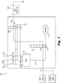
Fig. 1 is a schematic view of an embodiment of a power monitoring relay system constructed in accordance with the present disclosure, showing a transformer rectifier unit (TRU) and a power quality sense device; and -
Fig. 2 is a schematic view of another embodiment of a power monitoring relay system constructed in accordance with the present disclosure, showing a contactor upstream from the TRU. - Reference will now be made to the drawings wherein like reference numerals identify similar structural features or aspects of the subject disclosure. For purposes of explanation and illustration, and not limitation, a partial view of an embodiment of a system in accordance with the disclosure is shown in
Fig. 1 and is designated generally byreference character 100. Other embodiments of systems in accordance with the disclosure, or aspects thereof, are shown inFig. 2 and described below. The systems and methods described herein provide for a power monitoring relay system with overcurrent and frequency protection that acts to maintain the power quality, while providing independence and segregation from the main control/protection system. - As shown in
Fig. 1 , a powermonitoring relay system 100, such as that used in an integrated control center, e.g. an electrical power distribution panel, includes a transformer rectifier unit (TRU) 102 and threeAC busses AC busses inputs first AC bus 104a is configured to supply power to afirst input 106a, thesecond AC bus 104b is configured to supply powersecond input 106b, andthird AC bus 104c is configured to supply power tothird input 106c.System 100 includes aTRU switch 105 that controls the TRU functionality generally, e.g. ON or OFF, and is not dependent on the power quality. For the purposes of the present disclosure, the TRU switch is ON. Thesystem 100 includes overcurrent protectors 118a, 118b and 118c on the first, second andthird AC busses system 100 includes a powerquality sense device 108, e.g. a power monitor relay, such as a V610 relay available from Leach ® Corporation, Buena Park, California, electrically connected to each of the first, second andthird AC busses system 100 includes an electrically heldcontactor 110 electrically connected between the TRU 102 and the powerquality sense device 108. The electrically heldcontactor 110 is configured and adapted to be switched ON or OFF atswitch 126 depending on whether the powerquality sense device 108 is energized or de-energized. - With continued reference to
Fig. 1 ,system 100 includes aDC bus 112 electrically connected to the electrically heldcontactor 110. The electrically heldcontactor 110 is between theoutput 114 of the TRU 102 and theDC bus 112. Thesystem 100 includes a28V power supply 116 electrically connected in series to electrically heldcontactor 110.Power supply 116 is from a generator control unit (GCU) or auxiliary generator control unit (AGCU). The powerquality sense device 108 is configured and adapted to sense frequency and current (voltage) of at least one of the first, second orthird AC busses - As shown in
Fig. 1 , if the powerquality sense device 108 detects AC power quality, e.g. voltage (v) or frequency (f), falling outside of a selected range for any of the threeAC busses quality sense device 108 is de-energized andswitch 122 is opened, causing theswitch 126 of electrically heldcontactor 110 to open disconnecting it from theDC load bus 112. Theswitch 126 is opened inFig. 1 . As an example, the V610-CJAB-100/125-AA provides a selected frequency range of 370 Hz <f< 430 Hz (e.g. Underfrequency = 370Hz; Overfrequency = 430Hz), and a selected voltage range of 100 V < v < 125 V (e.g. Undervoltage = 100V, Overvoltage = 125V). The V610-CJAB-100/125-AA has accuracy of ±2% to ±10% for voltage and ±2% for frequency. The V610-CJAB-100/125-AA has a pickup time delay of approximately 50 to 10 ms ±10% and a dropout time delay of 50 to 10 ms ±10%. Switch 122 of powerquality sense device 108 is wired in series with a TRUoutput contactor coil 124. - With reference now to
Fig. 1 , the powerquality sense device 108 is electrically connected to each of the first, second andthird AC busses respective inputs TRU 102. The powerquality sense device 108 is configured to detect whether the power quality across the AC busses 104a, 104b, or 104c falls outside of the selected acceptable ranges described above. If the AC power quality for any of the threeAC busses quality sense device 108 is configured to be de-energized. When powerquality sense device 108 is de-energized, theswitch 122 is opened, removing aground path 107 and disconnecting it from the bus ofpower supply 116. Without power frompower supply 116, TRUoutput contactor coil 124 is de-energized, thereby switching electrically heldcontactor 110 OFF by way ofswitch 126. - With continued reference to
Fig. 1 , the powerquality sense device 108 is configured to be energized if the power quality for each of the AC busses 104a, 104b and 104c is within the selected acceptable range. In other words, each AC phase has to individually meet the power quality standards for the powerquality sense device 108 to be energized. When powerquality sense device 108 is energized, theswitch 122 is closed (ON) andground path 107 is provided. Whenground path 107 is provided, power from 116 flows into TRUoutput contactor coil 124 and TRUoutput contactor coil 124 is energized, thereby switching electrically heldcontactor 110 ON by way ofswitch 126. The ON position is indicated schematically by broken lines inFig. 1 . - As shown in
Fig. 2 , an alternative embodiment of a powermonitoring relay system 200 includes aTRU 202 and threeAC busses system 200 is the same assystem 100 except that an electrically heldcontactor 210 is a three-phase contactor and is electrically connected between theTRU 202 and the powerquality sense device 208 upstream from theTRU 202 instead of downstream from the TRU.System 200 includes aTRU switch 205, similar to switch 105. The power qualitymonitor sense device 208 senses voltage upstream of this threephase contactor 210. TheTRU 202 includes threeinputs inputs system 200 includesovercurrent protectors third AC busses - With continued reference to
Fig. 2 ,system 200 includes aDC bus 212, similar toDC bus 112, electrically connected theoutput 214 of theTRU 202. Thesystem 200 includes a28V power supply 216 electrically connected in series to electrically heldcontactor 210.Power supply 216 is the same aspower supply 116. Switch 222 of powerquality sense device 208 is wired in series with a TRUoutput contactor coil 224. Similar tosystem 100, if the powerquality sense device 208 detects AC power quality, e.g. voltage (v) or frequency (f), falling outside of a selected range for any of the threeAC busses quality sense device 208 is de-energized and switch 222 is opened. This causesground path 207 to be removed and power into TRUoutput contactor coil 224 to be stopped, thereby switching electrically heldcontactor 210 OFF by way ofswitches 226a-226c disconnecting from theDC load bus 212. If powerquality sense device 208 detects AC power quality, e.g. voltage (v) or frequency (f), within the selected range for each of the threeAC busses quality sense device 208 is energized and switch 222 is closed, similar to that described above with respect to powerquality sense device 108. - A method of power quality detection includes detecting a power quality in at least one of three AC busses, e.g.
AC busses 104a-104c or 204a-204c, with a power quality sense device, e.g. powerquality sense device contactor e.g. output e.g. ground path e.g. switch - The methods and systems of the present disclosure, as described above and shown in the drawings, provide for a power monitor relay system that monitors over-voltage, under-voltage and frequency at the AC inputs into the TRU, thereby reducing the need for multiple power quality monitors and providing an extra component of monitoring through the frequency monitoring. While the apparatus and methods of the subject disclosure have been shown and described with reference to preferred embodiments, those skilled in the art will readily appreciate that changes and/or modifications may be made thereto without departing from the scope of the subject disclosure as defined by the claims.
Claims (15)
- A system comprising:a transformer rectifier unit, TRU (102), having three inputs (106a-c);a first AC bus (104a) configured to supply power to a first (106a) of the three inputs;a second AC bus (104b) configured to supply power to a second (106b) of the three inputs;a third AC bus (104c) configured to supply power to a third (106c) of the three inputs;a power quality sense device (108) electrically connected to each of the first, second and third AC busses; andan electrically held contactor (110) electrically connected between the TRU and the power quality sense device, wherein the electrically held contactor is configured and adapted to be switched ON or OFF depending on whether the power quality sense device is energized or de-energized.
- The system as recited in claim 1, wherein the power quality sense device is configured to be energized if the power quality across the AC busses is within a selected acceptable range.
- The system as recited in any preceding claim, wherein the electrically held contactor is switched ON when the power quality sense device is energized.
- The system as recited in any preceding claim, wherein the power quality sense device is configured to be de-energized if the power quality across the AC busses is outside of a selected acceptable range.
- The system as recited in any preceding claim, wherein the electrically held contactor is switched OFF when the power quality sense device is energized.
- The system as recited in any preceding claim, further comprising a DC bus (112) electrically connected to the electrically held contactor, wherein the electrically held contactor is between the output of the TRU and the DC bus.
- The system as recited in any preceding claim, further comprising a 28V power supply (116) electrically connected in series to the electrically held contactor.
- The system as recited in any preceding claim, wherein the power quality sense device is configured and adapted to sense frequency and current of at least one of the first, second or third AC busses.
- The system as recited in any preceding claim, further comprising respective overcurrent protectors (118a,118b,118c) on the first, second and third AC busses.
- The system as recited in any preceding claim, wherein the power quality sense device is electrically connected to each of the first, second and third AC busses at respective sense points (120a,120b,120c) between the respective overcurrent protectors and the three inputs of the TRU.
- A method of power quality detection comprising:detecting a power quality in at least one of three AC busses (104a,104b,104c) with a power quality sense device (108);energizing the power quality sense device and switching an electrically held contactor (110) ON if the power quality in at least one of the three AC busses is within a selected acceptable range; andde-energizing the power quality sense device and switching an electrically held contactor OFF if the power quality in at least one of the three AC busses is outside of the selected acceptable range to stop power to a DC bus.
- The method as recited in claim 11, wherein detecting the power quality includes detecting at least one of voltage or frequency.
- The method as recited in claim 11 or 12, wherein the selected acceptable range includes a selected acceptable voltage range and a selected acceptable frequency range.
- The method as recited in claim 11, 12, or 13, further comprising a 28V power supply electrically connected in series to the electrically held contactor and the power quality sense device, wherein energizing the power quality sense device includes providing a ground path through the energizing sense device for the 28V power supply, thereby switching the electrically held contactor ON.
- The method as recited in any of claims 11 to 14, further comprising a 28V power supply (116) electrically connected in series to the electrically held contactor and the power quality sense device, wherein de-energizing the power quality sense device includes breaking a ground path through the energizing sense device for the 28V power supply, thereby switching the electrically held contactor OFF.
Applications Claiming Priority (1)
| Application Number | Priority Date | Filing Date | Title |
|---|---|---|---|
| US16/820,598 US11349299B2 (en) | 2020-03-16 | 2020-03-16 | Transformer rectifier unit power quality protection |
Publications (1)
| Publication Number | Publication Date |
|---|---|
| EP3883104A1 true EP3883104A1 (en) | 2021-09-22 |
Family
ID=74871312
Family Applications (1)
| Application Number | Title | Priority Date | Filing Date |
|---|---|---|---|
| EP21162129.7A Withdrawn EP3883104A1 (en) | 2020-03-16 | 2021-03-11 | Transformer rectifier unit power quality protection |
Country Status (2)
| Country | Link |
|---|---|
| US (2) | US11349299B2 (en) |
| EP (1) | EP3883104A1 (en) |
Cited By (2)
| Publication number | Priority date | Publication date | Assignee | Title |
|---|---|---|---|---|
| EP4178065A1 (en) * | 2021-11-05 | 2023-05-10 | Hamilton Sundstrand Corporation | Transformer rectifier unit (tru) backfeed interlock |
| EP4224661A3 (en) * | 2022-02-07 | 2023-08-23 | Hamilton Sundstrand Corporation | Built in test for transformer rectifier unit backfeed interlock |
Families Citing this family (1)
| Publication number | Priority date | Publication date | Assignee | Title |
|---|---|---|---|---|
| US11349299B2 (en) * | 2020-03-16 | 2022-05-31 | Hamilton Sundstrand Corporation | Transformer rectifier unit power quality protection |
Citations (3)
| Publication number | Priority date | Publication date | Assignee | Title |
|---|---|---|---|---|
| US20120104160A1 (en) * | 2010-10-28 | 2012-05-03 | Airbus Operations (S.A.S.) | Aerodyne including motorized undercarriages |
| EP2797194A1 (en) * | 2013-04-26 | 2014-10-29 | Hamilton Sundstrand Corporation | Systems and methods for electronic TRU input protection |
| EP2880734A1 (en) * | 2012-07-30 | 2015-06-10 | Kawasaki Jukogyo Kabushiki Kaisha | Electric system stabilizing system for aircraft |
Family Cites Families (9)
| Publication number | Priority date | Publication date | Assignee | Title |
|---|---|---|---|---|
| EP0955660A1 (en) | 1998-05-08 | 1999-11-10 | Schurter AG | Electric circuit breaker for apparatus having a current overload and undervoltage function and a current overload sensor therefore |
| SE0201432D0 (en) | 2002-04-29 | 2002-05-13 | Emerson Energy Systems Ab | A Power supply system and apparatus |
| JP4616397B2 (en) * | 2009-02-23 | 2011-01-19 | ファナック株式会社 | PWM rectifier |
| ES2710555T3 (en) * | 2010-10-06 | 2019-04-25 | General Electric Technology Gmbh | Procedure and device to protect an ESP power supply for transient overvoltages in the electrical network |
| US8699188B2 (en) * | 2010-10-27 | 2014-04-15 | Hamilton Sundstrand Corporation | Shunt regulator for overvoltage protection at transformer rectifier unit of electrical generating system |
| WO2013056751A1 (en) * | 2011-10-21 | 2013-04-25 | Abb Research Ltd | Method and system for detecting a failed rectifier in an ac/dc convertor |
| US9973097B2 (en) | 2016-06-21 | 2018-05-15 | Astronics Advanced Electronic Systems Corp. | Regulating transformer rectifier unit with multiple circuits for preventing output overvoltage |
| US11133665B2 (en) * | 2018-08-29 | 2021-09-28 | Hamilton Sundstrand Corporation | Direct current over voltage monitoring and protection |
| US11349299B2 (en) * | 2020-03-16 | 2022-05-31 | Hamilton Sundstrand Corporation | Transformer rectifier unit power quality protection |
-
2020
- 2020-03-16 US US16/820,598 patent/US11349299B2/en active Active
-
2021
- 2021-03-11 EP EP21162129.7A patent/EP3883104A1/en not_active Withdrawn
-
2022
- 2022-05-27 US US17/827,422 patent/US11710959B2/en active Active
Patent Citations (3)
| Publication number | Priority date | Publication date | Assignee | Title |
|---|---|---|---|---|
| US20120104160A1 (en) * | 2010-10-28 | 2012-05-03 | Airbus Operations (S.A.S.) | Aerodyne including motorized undercarriages |
| EP2880734A1 (en) * | 2012-07-30 | 2015-06-10 | Kawasaki Jukogyo Kabushiki Kaisha | Electric system stabilizing system for aircraft |
| EP2797194A1 (en) * | 2013-04-26 | 2014-10-29 | Hamilton Sundstrand Corporation | Systems and methods for electronic TRU input protection |
Non-Patent Citations (2)
| Title |
|---|
| ESTERLINE ET AL: "V710 AC VOLTAGE SENSOR, 2 PDT OR 4 PDT, 10 AMP GENERAL CHARACTERISTICS CARACTERISTIQUES GENERALES", 1 October 2014 (2014-10-01), pages 1 - 4, XP055824934, Retrieved from the Internet <URL:https://eu.leachint.fr/aerospace/v710/> [retrieved on 20210715] * |
| V610 SERIES ET AL: "ENGINEERING DATA SHEET Date of issue: 3/07 -7", 1 March 2007 (2007-03-01), pages 1 - 3, XP055824935, Retrieved from the Internet <URL:https://www.scnnordic.com/storage/5553AD4AEF69F892B69A4E2110B55E451B1AAD6BDBA212B3A332D7418DC6AE68/973819618761445f9901e68928b2c3a1/pdf/media/fba10facad30478b98f2cd568be3e657/V610.pdf> [retrieved on 20210715] * |
Cited By (4)
| Publication number | Priority date | Publication date | Assignee | Title |
|---|---|---|---|---|
| EP4178065A1 (en) * | 2021-11-05 | 2023-05-10 | Hamilton Sundstrand Corporation | Transformer rectifier unit (tru) backfeed interlock |
| US11996690B2 (en) | 2021-11-05 | 2024-05-28 | Hamilton Sundstrand Corporation | Transformer rectifier unit (TRU) backfeed interlock |
| EP4224661A3 (en) * | 2022-02-07 | 2023-08-23 | Hamilton Sundstrand Corporation | Built in test for transformer rectifier unit backfeed interlock |
| US12099096B2 (en) | 2022-02-07 | 2024-09-24 | Hamilton Sundstrand Corporation | Built in test (BIT) for transformer rectifier unit (TRU) backfeed interlock |
Also Published As
| Publication number | Publication date |
|---|---|
| US11349299B2 (en) | 2022-05-31 |
| US11710959B2 (en) | 2023-07-25 |
| US20220285930A1 (en) | 2022-09-08 |
| US20210288488A1 (en) | 2021-09-16 |
Similar Documents
| Publication | Publication Date | Title |
|---|---|---|
| US11710959B2 (en) | Transformer rectifier unit power quality protection | |
| US4639817A (en) | Protective relay circuit for detecting arcing faults on low-voltage spot networks | |
| US2813243A (en) | Rectifier system | |
| Vanteddu et al. | Protection design and coordination of DC distributed power systems architectures | |
| US20130286515A1 (en) | Fault Protection for Aircraft Power Systems | |
| US20200295594A1 (en) | Uninterruptible power supply | |
| US12334775B2 (en) | Power supply system and control method | |
| SE510192C2 (en) | Procedure and switching arrangements to reduce problems with three-tier currents that may occur in alternator and motor operation of AC machines connected to three-phase distribution or transmission networks | |
| US11374391B2 (en) | Electrical AC/DC converter arrangement with an AC circuit breaker, and a method for disconnecting an AC/DC converter arrangement | |
| EP4145655A1 (en) | Device, method, and power distribution system for preventing electric shock and fire in case of short circuit and ground fault | |
| JPH10513034A (en) | Faulty bridge power rectifier detection and isolation circuit and electrical system using the same | |
| US4346422A (en) | Power-distribution network for telecommunication system | |
| JP2001320828A (en) | Ground relay with failed-area determining function | |
| JPH11289670A (en) | Bipolar DC transmission system | |
| KR101636479B1 (en) | Method And Apparatus for Breaking Fault Current | |
| JPH06233459A (en) | Power system protective system | |
| EP4303904A1 (en) | Multiphase ground fault circuit interrupter | |
| KR100527628B1 (en) | Operation Method for Static Condenser Bank with Vacuum Circuit Breaker | |
| US2214858A (en) | Protective arrangement for electric power circuits | |
| JPH11308758A (en) | Ground fault detector | |
| EP3879659A1 (en) | Ac essential bus delta current and overcurrent protection scheme | |
| SU1675995A2 (en) | Device for protective disconnection of electrical installation from alternating current circuit | |
| JP2000092708A (en) | Harmonic current suppression device | |
| JPH02303334A (en) | Ac power source device | |
| CN115296274A (en) | Fault positioning and bus protection method and system |
Legal Events
| Date | Code | Title | Description |
|---|---|---|---|
| PUAI | Public reference made under article 153(3) epc to a published international application that has entered the european phase |
Free format text: ORIGINAL CODE: 0009012 |
|
| STAA | Information on the status of an ep patent application or granted ep patent |
Free format text: STATUS: THE APPLICATION HAS BEEN PUBLISHED |
|
| AK | Designated contracting states |
Kind code of ref document: A1 Designated state(s): AL AT BE BG CH CY CZ DE DK EE ES FI FR GB GR HR HU IE IS IT LI LT LU LV MC MK MT NL NO PL PT RO RS SE SI SK SM TR |
|
| STAA | Information on the status of an ep patent application or granted ep patent |
Free format text: STATUS: REQUEST FOR EXAMINATION WAS MADE |
|
| 17P | Request for examination filed |
Effective date: 20220321 |
|
| RBV | Designated contracting states (corrected) |
Designated state(s): AL AT BE BG CH CY CZ DE DK EE ES FI FR GB GR HR HU IE IS IT LI LT LU LV MC MK MT NL NO PL PT RO RS SE SI SK SM TR |
|
| STAA | Information on the status of an ep patent application or granted ep patent |
Free format text: STATUS: EXAMINATION IS IN PROGRESS |
|
| 17Q | First examination report despatched |
Effective date: 20240808 |
|
| STAA | Information on the status of an ep patent application or granted ep patent |
Free format text: STATUS: THE APPLICATION HAS BEEN WITHDRAWN |
|
| 18W | Application withdrawn |
Effective date: 20251020 |