EP3883062A1 - Radiating coaxial cable - Google Patents
Radiating coaxial cable Download PDFInfo
- Publication number
- EP3883062A1 EP3883062A1 EP21163558.6A EP21163558A EP3883062A1 EP 3883062 A1 EP3883062 A1 EP 3883062A1 EP 21163558 A EP21163558 A EP 21163558A EP 3883062 A1 EP3883062 A1 EP 3883062A1
- Authority
- EP
- European Patent Office
- Prior art keywords
- radiating
- cable
- apertures
- coaxial cable
- conductive shield
- Prior art date
- Legal status (The legal status is an assumption and is not a legal conclusion. Google has not performed a legal analysis and makes no representation as to the accuracy of the status listed.)
- Withdrawn
Links
- 230000005855 radiation Effects 0.000 claims abstract description 41
- 239000004020 conductor Substances 0.000 claims description 19
- 229910052751 metal Inorganic materials 0.000 claims description 13
- 239000002184 metal Substances 0.000 claims description 13
- 230000007704 transition Effects 0.000 claims description 10
- 238000000034 method Methods 0.000 claims description 9
- 230000003121 nonmonotonic effect Effects 0.000 claims description 8
- 239000011888 foil Substances 0.000 claims description 7
- 230000008569 process Effects 0.000 claims description 5
- 238000004519 manufacturing process Methods 0.000 claims description 4
- 238000009434 installation Methods 0.000 description 11
- 230000003247 decreasing effect Effects 0.000 description 7
- 230000007423 decrease Effects 0.000 description 4
- 230000001747 exhibiting effect Effects 0.000 description 3
- RYGMFSIKBFXOCR-UHFFFAOYSA-N Copper Chemical compound [Cu] RYGMFSIKBFXOCR-UHFFFAOYSA-N 0.000 description 2
- 239000004698 Polyethylene Substances 0.000 description 2
- 239000004411 aluminium Substances 0.000 description 2
- 229910052782 aluminium Inorganic materials 0.000 description 2
- XAGFODPZIPBFFR-UHFFFAOYSA-N aluminium Chemical compound [Al] XAGFODPZIPBFFR-UHFFFAOYSA-N 0.000 description 2
- 230000008859 change Effects 0.000 description 2
- 239000002131 composite material Substances 0.000 description 2
- 229910052802 copper Inorganic materials 0.000 description 2
- 239000010949 copper Substances 0.000 description 2
- 230000008878 coupling Effects 0.000 description 2
- 238000010168 coupling process Methods 0.000 description 2
- 238000005859 coupling reaction Methods 0.000 description 2
- 239000003063 flame retardant Substances 0.000 description 2
- 239000000463 material Substances 0.000 description 2
- -1 polyethylene Polymers 0.000 description 2
- 229920000573 polyethylene Polymers 0.000 description 2
- RNFJDJUURJAICM-UHFFFAOYSA-N 2,2,4,4,6,6-hexaphenoxy-1,3,5-triaza-2$l^{5},4$l^{5},6$l^{5}-triphosphacyclohexa-1,3,5-triene Chemical compound N=1P(OC=2C=CC=CC=2)(OC=2C=CC=CC=2)=NP(OC=2C=CC=CC=2)(OC=2C=CC=CC=2)=NP=1(OC=1C=CC=CC=1)OC1=CC=CC=C1 RNFJDJUURJAICM-UHFFFAOYSA-N 0.000 description 1
- 230000004888 barrier function Effects 0.000 description 1
- 230000001186 cumulative effect Effects 0.000 description 1
- 239000012777 electrically insulating material Substances 0.000 description 1
- 238000003780 insertion Methods 0.000 description 1
- 230000037431 insertion Effects 0.000 description 1
- 239000007787 solid Substances 0.000 description 1
- 229920001169 thermoplastic Polymers 0.000 description 1
- 239000004416 thermosoftening plastic Substances 0.000 description 1
- DXZMANYCMVCPIM-UHFFFAOYSA-L zinc;diethylphosphinate Chemical compound [Zn+2].CCP([O-])(=O)CC.CCP([O-])(=O)CC DXZMANYCMVCPIM-UHFFFAOYSA-L 0.000 description 1
Images




Classifications
-
- H—ELECTRICITY
- H01—ELECTRIC ELEMENTS
- H01Q—ANTENNAS, i.e. RADIO AERIALS
- H01Q13/00—Waveguide horns or mouths; Slot antennas; Leaky-waveguide antennas; Equivalent structures causing radiation along the transmission path of a guided wave
- H01Q13/20—Non-resonant leaky-waveguide or transmission-line antennas; Equivalent structures causing radiation along the transmission path of a guided wave
- H01Q13/203—Leaky coaxial lines
-
- H—ELECTRICITY
- H01—ELECTRIC ELEMENTS
- H01B—CABLES; CONDUCTORS; INSULATORS; SELECTION OF MATERIALS FOR THEIR CONDUCTIVE, INSULATING OR DIELECTRIC PROPERTIES
- H01B11/00—Communication cables or conductors
- H01B11/18—Coaxial cables; Analogous cables having more than one inner conductor within a common outer conductor
- H01B11/1808—Construction of the conductors
-
- H—ELECTRICITY
- H01—ELECTRIC ELEMENTS
- H01B—CABLES; CONDUCTORS; INSULATORS; SELECTION OF MATERIALS FOR THEIR CONDUCTIVE, INSULATING OR DIELECTRIC PROPERTIES
- H01B13/00—Apparatus or processes specially adapted for manufacturing conductors or cables
- H01B13/06—Insulating conductors or cables
-
- H—ELECTRICITY
- H01—ELECTRIC ELEMENTS
- H01B—CABLES; CONDUCTORS; INSULATORS; SELECTION OF MATERIALS FOR THEIR CONDUCTIVE, INSULATING OR DIELECTRIC PROPERTIES
- H01B13/00—Apparatus or processes specially adapted for manufacturing conductors or cables
- H01B13/22—Sheathing; Armouring; Screening; Applying other protective layers
-
- H—ELECTRICITY
- H01—ELECTRIC ELEMENTS
- H01B—CABLES; CONDUCTORS; INSULATORS; SELECTION OF MATERIALS FOR THEIR CONDUCTIVE, INSULATING OR DIELECTRIC PROPERTIES
- H01B13/00—Apparatus or processes specially adapted for manufacturing conductors or cables
- H01B13/22—Sheathing; Armouring; Screening; Applying other protective layers
- H01B13/26—Sheathing; Armouring; Screening; Applying other protective layers by winding, braiding or longitudinal lapping
-
- H—ELECTRICITY
- H01—ELECTRIC ELEMENTS
- H01Q—ANTENNAS, i.e. RADIO AERIALS
- H01Q1/00—Details of, or arrangements associated with, antennas
- H01Q1/007—Details of, or arrangements associated with, antennas specially adapted for indoor communication
Definitions
- the present disclosure relates to the field of coaxial cables.
- the present disclosure relates to a radiating coaxial cable and to a process for manufacturing a radiating coaxial cable.
- a radiating coaxial cable is a coaxial cable configured to emit and receive radio waves at a specific radiofrequency or in a specific radiofrequency range, so as to function as an extended antenna.
- Radiating coaxial cables are typically used to provide uniform radiofrequency coverage (for example, mobile coverage) to extended and/or narrow indoor environments, such as tunnels (metro, railway and road tunnels), buildings (e.g. office corridors, shopping centers or parking garages), mines or ships.
- Known coaxial cables comprise an inner conductor surrounded by an insulating layer, a tubular conductive shield (a.k.a. "outer conductor") and a jacket, which is typically the outermost cable layer.
- a tubular conductive shield a.k.a. "outer conductor”
- a jacket typically the outermost cable layer.
- a plurality of apertures like slots or holes is punched/milled through in the shield to allow the radio waves to leak into and out of the cable along its length.
- the power radiated by a radiating coaxial cable has an angular dependence, namely a radiation pattern.
- the radiation pattern may be represented graphically as a plot of the radiated power as received by a test receiver, placed at a predefined distance from the cable (e.g. 4 meters), as a function of the receiver angular position.
- the radiation pattern typically shows one or more radiated power maxima called “lobes" separated by "nulls" at which the radiated power is substantially lower, even zero.
- the shape of the radiation pattern depends on the arrangement of the radiating apertures in the cable shield.
- a single straight line of radiating apertures may be provided in the cable shield, so that the coaxial cable (a.k.a. "RFX cable”) has a single radiating side.
- the radiation pattern exhibits a single, large lobe centered at the angular position of the radiating apertures.
- two diametrically opposed straight lines of radiating apertures may be provided in the cable shield, so that the coaxial cable (a.k.a. "RF2X” cable”) has two opposite radiating sides. In this case, the radiation pattern exhibits two substantially diametrically opposed lobes.
- US 5,276,413 describes a radiating cable whose shield has a number of openings increasing along the cable. The increase in the number of openings along the cable nearly balances any decrease in the radiated power caused by attenuation of the cable. The radiated power then remains approximately constant along the cable.
- the rooms to be covered may vary in size and arrangement.
- all the rooms may be arranged on a single side of a corridor, while in other areas of the building (or even other parts of the same corridor) the rooms could be arranged on both sides.
- Large rooms such as auditorium, canteen or meeting rooms require a wider coverage.
- other areas of the building could require no coverage at all, e.g. areas that shall be radiation-free for safety reasons (for instance some rooms in a hospital) or passages where no coverage is needed. Some areas could be covered by a reduced field strength.
- a non-uniform radiofrequency coverage could be provided by installing in the various building areas (e.g. along the corridors of the building) lengths of radiating coaxial cables of different types, such as RFX and RF2X.
- RFX radiofrequency
- RF2X radiofrequency radiated power
- RFX cable with higher radiated power for example, with larger radiating apertures
- the various lengths of cables of different types should be reciprocally joined, so as to form a single coverage system which may be fed by a radiofrequency source at one its ends.
- the Applicant has then faced the problem of providing a radiating coaxial cable which allows reducing duration, complexity and cost of installation in contexts wherein a non-uniform radiofrequency coverage is required, such as for example a building wherein rooms to be covered vary in size and arrangement.
- this problem is solved by a radiating coaxial cable whose conductive shield comprises, from end to end, a plurality of radiating apertures, wherein at least one geometric property of the radiating apertures is varied along the longitudinal direction of the cable so as to longitudinally vary the shape of the radiation pattern of the cable in a predefined way.
- geometric property of the radiating apertures comprises either a geometric property of the single radiating aperture, in particular shape, size, orientation or angular position, or a geometric property collectively describing the arrangement of radiating apertures in a set on the cable shield, in particular their reciprocal radial and/or longitudinal position, the number of lines according to which they are arranged and the shape of such line(s) (straight, wavy, helical and so on).
- varying the shape of the radiation pattern of the cable it is meant varying the number of lobes and/or the angular position(s) of the lobe(s) and/or the angular width of the lobe(s) and/or the amplitude of the lobe(s).
- the radiating coaxial cable allows providing a non-uniform radiofrequency coverage by installing a single cable.
- the geometric properties of the radiating apertures may be varied along the cable, so as to longitudinally vary the shape of the radiation pattern to meet the coverage requirements of the various areas crossed by the cable.
- the radiating apertures may be arranged in a single longitudinal straight line, resulting in a radiation pattern with a single lobe providing radiofrequency coverage in an area with e.g. rooms arranged on a single side of the corridor; the first section may be followed by a second section where the radiating apertures are arranged in two diametrically opposed longitudinal straight lines, resulting in a radiation pattern with two lobes providing radiofrequency coverage in an area with e.g. rooms arranged on both sides of the corridor; and so on.
- a radiating coaxial cable comprising:
- the cable comprises at least two contiguous sections having different arrangements of the radiating apertures and radiation patterns with different shapes.
- the arrangement of the radiating apertures in each one of the at least two contiguous sections comprises a single alignment, a double alignment or a multiple alignment of radiating apertures.
- the transition between the arrangements of radiating apertures in two contiguous sections may be single-step or gradual.
- the cable comprises at least one section wherein the at least one geometric property of the radiating apertures is varied in a non-monotonic way.
- the cable also comprises at least one section with no radiating apertures.
- the present disclosure relates to a process for manufacturing a radiating coaxial cable, said process comprising:
- the present disclosure relates to a method for providing a varying radiofrequency coverage comprising transmitting a radiofrequency signal by using a single radiating coaxial cable comprising:
- the frequency of the radiofrequency signal transmitted by the cable of the present disclosure can vary from 20 kHz to 10 GHz, for example from 5 MHz to 4 GHz.
- Figure 1 shows a lateral view of a portion of a radiating coaxial cable 10 according to an embodiment of the present disclosure.
- the cable 10 comprises an inner conductor 2 surrounded by an insulating layer 3, a tubular conductive shield 4 and a jacket 5.
- the jacket 5 may be the outermost layer of the cable 10.
- the cable 10 may also comprise other layers (e.g. a fire barrier or wrapping tape interposed between conductive shield 4 and jacket 5 and/or interposed between insulating layer 3 and conductive shield 4), which are not shown in the Figures and will not be described herein below.
- the inner conductor 2 may be single core or multicore, hollow or solid. In case of hollow conductor/s, it/they can be in form of a corrugated welded tube.
- the inner conductor 2 is made of an electrically conductive metal such as copper, aluminium or composite thereof.
- the inner conductor 2 can have an outer diameter comprised between 1 mm and 25 mm.
- the insulating layer 3 can be made of polyethylene, optionally foamed, or other suitable electrically insulating material.
- the insulating layer 3 can have an outer diameter comprised between 5 mm and 55 mm and a thickness comprised between 1 mm and 20 mm.
- the tubular conductive shield 4 is made of an electrically conductive metal such as copper, aluminium or composite thereof.
- the shield 4 may be either a smooth or corrugated metal layer.
- the shield metal layer may be in form of a metal foil longitudinally wrapped around the insulating layer 3 and either welded or with glued lapping rims.
- the conductive shield 4 can have an outer diameter comprised between 5 mm and 60 mm and a thickness comprised between 0.03 mm and 4 mm (including corrugations, if present).
- the jacket 5 is made of a polymeric material, such as polyethylene.
- the jacket 5 may have flame retardant properties.
- the jacket 5 may be made of a halogen free flame retardant polymeric material, either thermoplastic or crosslinked.
- the conductive shield 4 is provided with a plurality of radiating apertures (not shown in Figure 1 ) allowing the radio waves to leak into and out of the cable 10, which accordingly acts as an antenna.
- the conductive shield 4 may be obtained by a single smooth metal foil, which is longitudinally wrapped (and optionally overlapped) about the insulating layer 3.
- the radiating apertures may be punched (or milled) through the smooth metal foil before it is wrapped about the insulating layer 3.
- At least one geometric property of the radiating apertures is varied along the longitudinal direction of the cable 10, so as to longitudinally vary the shape of the radiation pattern of the cable 10 in a predefined way.
- one or more of the following geometric properties may be varied:
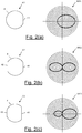
- Figures 2(a)-(g) show exemplary arrangements of the radiating apertures in a cable according to the present disclosure and, for each shown arrangement, the resulting radiation pattern.
- the radiation patterns depicted in Figures 2(a)-(g) are qualitative and schematic.
- an arrangement A1 wherein a plurality of radiating apertures is arranged in a single straight line 41 provides a radiation pattern RP1 exhibiting a single, large lobe substantially centred at the angular position of the radiating apertures.
- an arrangement A2 wherein a plurality of radiating apertures is arranged in a first straight line 41 and in a second straight line 42 diametrically opposed one another provides a radiation pattern RP2 exhibiting two substantially diametrically opposed lobes. If the shape, size and reciprocal distance of the apertures in the first line 41 and second line 42 are substantially the same, the two lobes substantially have the same angular width and amplitude.
- Figure 2(c) depicts instead an arrangement A3 wherein the radiating apertures in the first line 41 are wider than the radiating apertures in the diametrically opposed second line 42.
- the resulting radiation pattern RP3 has two lobes having different angular widths and amplitudes, the lobe centred at the angular position of the first line 41 of wider apertures having a larger angular width and amplitude then the other one.
- Figure 2(d) depicts an arrangement A4 wherein the first line 41 of radiating apertures and the second line 42 of radiating apertures, having substantially the same dimension, are not diametrically opposed, but are instead located at angular positions spaced by an angle comprised between 90° and 180°.
- the resulting radiation pattern RP4 has two lobes which are not diametrically opposed, but are instead roughly centred at the angular positions of the respective lines 41, 42 of radiating apertures.
- Figure 2(e) depicts an arrangement A5 wherein the angle between the angular positions of the first line 41 of radiating apertures and second line 42 of radiating apertures is decreased until the radiating apertures of the two lines 41, 42 are substantially merged into a single line of very large radiating apertures.
- the resulting radiation pattern RP5 has a single lobe, whose amplitude and angular width are particularly high.
- an arrangement A6 of radiating apertures distributed in four longitudinal lines 41, 42, 43, 44 located at angular positions reciprocally spaced by angles of 90° results in a radiation pattern RP6 exhibiting four lobes centred at the angular positions of the lines 41, 42, 43, 44, respectively. If the shape, size and reciprocal spacing of the radiating apertures is substantially the same in all four lines 41, 42, 43, 44, the four lobes substantially have the same angular width and amplitude. Otherwise, the lobes may have different angular widths and amplitudes, as discussed above with reference to Figure 2(c) .
- the radiation pattern RP7 is null, namely the cable 10 behaves as a normal (namely, non radiating) coaxial cable.
- Figures 2(a)-(g) are merely exemplary. Other arrangements of the radiating apertures along a cable and between the cable ends may be provided, which result in radiation patterns with other shapes.
- the variation of the geometric properties of the radiating apertures in the longitudinal direction of the cable 10 may be implemented as a transition from one of the arrangements A1-A6 shown in Figures 2(a)-2(f) (or any other possible known arrangement) to another one of such arrangements.
- Such transition results in a variation of the shape of the radiation pattern of the cable 10.
- a transition from the arrangement A1 (single straight line of radiating apertures) to the arrangement A2 or A3 (two diametrically opposed straight lines of radiating apertures) results in a change of the number of lobes of the radiation pattern (from 1 to 2).
- a transition from the arrangement A2 (two diametrically opposed straight lines of radiating apertures with substantially the same shape and size) to the arrangement A3 (two diametrically opposed straight lines of radiating apertures with substantially the same shape but different sizes) A3 results in a change of the relative amplitudes of the two lobes of the radiation pattern.
- transitions may be provided along a single cable 10, so that its conductive shield 4 is virtually divided into a number of contiguous sections (e.g. sections 4A, 4B, 4C in Figure 1 ), each section being provided with a respective arrangement of radiating apertures and, hence, with a respective radiation pattern having a certain shape.
- sections 4A, 4B, 4C in Figure 1 may have no radiating apertures, as depicted in Figure 2(f) .
- the transition between the arrangements of two consecutive sections 4A-4B or 4B-4C may be either single-step or gradual.
- transition between the arrangement A1 (single straight line of radiating apertures) to the arrangement A2 (two diametrically opposed straight lines of radiating apertures) or vice versa may be single-step.
- transition from the arrangement A2 (two diametrically opposed straight lines of radiating apertures with the same shape and size) to the arrangement of A3 (two diametrically opposed straight lines of radiating apertures with the same shape but different sizes) may be implemented by gradually increasing the size of the radiating apertures in the first line 41 from their smaller size in the arrangement A2 to their larger size in the arrangement of A3.
- the radiated power slightly decreases along the cable 10, due to attenuation of the cable 10.
- a geometric property of the radiating apertures such as their size or their reciprocal distance
- the radiation pattern still exhibits a single lobe, but its amplitude - namely, the radiated power - may be varied longitudinally in a purported way.
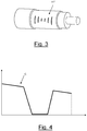
- Figures 3 shows a variant A1' of the arrangement A1 of Figure 2(a) (radiating apertures in a single straight line). As described above, the resulting radiation pattern has a single lobe whose amplitude is indicative of the power radiated by the cable 10.
- a geometric property (the size) of the radiating apertures in the conductive shield 4 is varied in a non-monotonic way longitudinally along the cable 10. For example the aperture size is firstly decreased to a minimum value, then kept constant and then increased again to the original value.
- Curve C is non-monotonic, namely it firstly exhibits a slight decrease due to attenuation in the cable 10, followed by a steeper decrease due to the cumulative effect of both attenuation and increasing coupling loss of the cable 10, the latter being due to the decreasing size of the radiating apertures according to the arrangement A1'.
- the radiated power is almost constantly equal to a minimum value for a length of the cable 10, which corresponds to an installation area where a low-radiofrequency coverage is required. Then, the radiated power exhibits a steep increase due to the decreasing coupling loss of the cable 10 corresponding to the size increasing of the radiating apertures according to the arrangement A1'. The radiated power finally exhibits again a slightly decreasing profile due to attenuation of the cable 10.
- the shape of the radiation pattern of the cable 10 may be longitudinally varied from end to end according to the radiofrequency coverage needs.
- the cable 10 may be used to provide a non-uniform radiofrequency coverage, e.g. in contexts (e.g. a building) wherein different areas have different coverage requirements are present.
- Figure 5 shows an exemplary scenario, wherein two buildings (e.g. of a same company) need to be provided with radiofrequency coverage.
- the first building B1 is a single floor building and has a first area AR1 with rooms arranged on both sides of a corridor, a second area AR2 with rooms arranged on a single side of the corridor and a third area AR3 with rooms on one side of the corridor and a larger room (e.g. a canteen) of the other side of the corridor.
- a fourth area AR4 corresponds to a cable passage between the two buildings.
- the second building B2 is instead a double floor building with a single area AR5 with rooms arranged on both sides of the corridor.
- a single radiating coaxial cable may be used, whose conductive shield has a section with radiating aperture arrangement designed for each area.
- the conductive shield of the cable may have a first section S1 for the area AR1, whose radiating apertures are arranged according to the arrangement A2 shown in Figure 2(b) .
- the first section S1 may be followed by a second section S2 for installation in area AR2, whose radiating apertures are arranged according to the arrangement A1 shown in Figure 2(a) .
- a non monotonic variation of the radiating apertures size may be provided if a particular longitudinal variation of the radiated power is desired across the area AR2.
- the second section S2 may be followed by a third section S3 for installation in the area AR3, whose radiating apertures are arranged according to the arrangement A3 shown in Figure 2(c) with, for example, the straight line 41 oriented towards the larger room of this area.
- the arrangement A5 shown in Figure 2(e) can be provided.
- the third section S3 may be followed by a fourth section S4 with no radiating apertures, for installation in the cable passage of area AR4.
- the fourth section S4 may be then followed by a fifth section S5 for installation in the area AR5, whose radiating apertures are arranged according to the arrangement A6 shown in Figure 2(f) to provide radiofrequency coverage to both the floors of the building B2.
Landscapes
- Engineering & Computer Science (AREA)
- Manufacturing & Machinery (AREA)
- Waveguide Aerials (AREA)
- Communication Cables (AREA)
Abstract
Disclosed is a radiating coaxial cable wherein at least one geometric property of the radiating apertures of the cable conductive shield is varied longitudinally, so as to longitudinally vary the shape of the radiation pattern of the cable in a predefined way. Such radiating coaxial cable allows providing a non-uniform radiofrequency coverage by installing a single cable. For example, in a building with different areas having different coverage requirements, the geometric properties of the radiating apertures of the cable may be varied so as to longitudinally vary the shape of the radiation pattern to meet the coverage requirements of the various areas crossed by the cable.
Description
- The present disclosure relates to the field of coaxial cables. In particular, the present disclosure relates to a radiating coaxial cable and to a process for manufacturing a radiating coaxial cable.
- As known, a radiating coaxial cable (also known as "leaky coaxial cable") is a coaxial cable configured to emit and receive radio waves at a specific radiofrequency or in a specific radiofrequency range, so as to function as an extended antenna. Radiating coaxial cables are typically used to provide uniform radiofrequency coverage (for example, mobile coverage) to extended and/or narrow indoor environments, such as tunnels (metro, railway and road tunnels), buildings (e.g. office corridors, shopping centers or parking garages), mines or ships.
- Known coaxial cables comprise an inner conductor surrounded by an insulating layer, a tubular conductive shield (a.k.a. "outer conductor") and a jacket, which is typically the outermost cable layer. In radiating coaxial cables, a plurality of apertures (like slots or holes) is punched/milled through in the shield to allow the radio waves to leak into and out of the cable along its length.
- The power radiated by a radiating coaxial cable has an angular dependence, namely a radiation pattern. The radiation pattern may be represented graphically as a plot of the radiated power as received by a test receiver, placed at a predefined distance from the cable (e.g. 4 meters), as a function of the receiver angular position. The radiation pattern typically shows one or more radiated power maxima called "lobes" separated by "nulls" at which the radiated power is substantially lower, even zero.
- The shape of the radiation pattern (in particular, the number of lobes and their angular position) depends on the arrangement of the radiating apertures in the cable shield. For example, a single straight line of radiating apertures may be provided in the cable shield, so that the coaxial cable (a.k.a. "RFX cable") has a single radiating side. In this case, the radiation pattern exhibits a single, large lobe centered at the angular position of the radiating apertures. As another example, two diametrically opposed straight lines of radiating apertures may be provided in the cable shield, so that the coaxial cable (a.k.a. "RF2X" cable") has two opposite radiating sides. In this case, the radiation pattern exhibits two substantially diametrically opposed lobes.
-
US 5,276,413 describes a radiating cable whose shield has a number of openings increasing along the cable. The increase in the number of openings along the cable nearly balances any decrease in the radiated power caused by attenuation of the cable. The radiated power then remains approximately constant along the cable. - The Applicant has noticed that, while the cable of
US 5,276,413 aims at providing a radiofrequency coverage as uniform as possible, in some contexts a non-uniform radiofrequency coverage could be instead desirable. - For example, within a building (e.g. with offices and/or manufacturing facilities), the rooms to be covered may vary in size and arrangement. For examples, in some areas of the building all the rooms may be arranged on a single side of a corridor, while in other areas of the building (or even other parts of the same corridor) the rooms could be arranged on both sides. Large rooms such as auditorium, canteen or meeting rooms require a wider coverage. Besides, other areas of the building could require no coverage at all, e.g. areas that shall be radiation-free for safety reasons (for instance some rooms in a hospital) or passages where no coverage is needed. Some areas could be covered by a reduced field strength.
- In principle, a non-uniform radiofrequency coverage could be provided by installing in the various building areas (e.g. along the corridors of the building) lengths of radiating coaxial cables of different types, such as RFX and RF2X. For instance, a length of RFX cable could be installed where the rooms to be covered are arranged on a single side of the corridor, a length of RF2X cable could be installed where the rooms are arranged on both sides of the corridor, while a length of RFX cable with higher radiated power (for example, with larger radiating apertures) could be installed where larger rooms such as auditorium or canteen are located. The various lengths of cables of different types should be reciprocally joined, so as to form a single coverage system which may be fed by a radiofrequency source at one its ends.
- The Applicant has noticed that using lengths of radiating coaxial cables of different types makes the installation procedure complex and costly. Joining the various cable lengths of different types is a complex and long operation, which moreover induces additional loss (namely, the insertion loss of the cable joints) in the overall coverage system. Some cable types moreover are not mutually compatible, so they cannot be joined. In this case, they must be fed separately by respective radio frequency sources, thereby further increasing the cost of the coverage system.
- The Applicant has then faced the problem of providing a radiating coaxial cable which allows reducing duration, complexity and cost of installation in contexts wherein a non-uniform radiofrequency coverage is required, such as for example a building wherein rooms to be covered vary in size and arrangement.
- According to embodiments of the present disclosure, this problem is solved by a radiating coaxial cable whose conductive shield comprises, from end to end, a plurality of radiating apertures, wherein at least one geometric property of the radiating apertures is varied along the longitudinal direction of the cable so as to longitudinally vary the shape of the radiation pattern of the cable in a predefined way.
- The expression "geometric property of the radiating apertures" comprises either a geometric property of the single radiating aperture, in particular shape, size, orientation or angular position, or a geometric property collectively describing the arrangement of radiating apertures in a set on the cable shield, in particular their reciprocal radial and/or longitudinal position, the number of lines according to which they are arranged and the shape of such line(s) (straight, wavy, helical and so on).
- By "varying the shape of the radiation pattern of the cable" it is meant varying the number of lobes and/or the angular position(s) of the lobe(s) and/or the angular width of the lobe(s) and/or the amplitude of the lobe(s).
- The radiating coaxial cable according to embodiments of the present disclosure allows providing a non-uniform radiofrequency coverage by installing a single cable. In the above exemplary scenario of a building with different areas having different coverage requirements, the geometric properties of the radiating apertures may be varied along the cable, so as to longitudinally vary the shape of the radiation pattern to meet the coverage requirements of the various areas crossed by the cable.
- For example, in a first section of the cable shield the radiating apertures may be arranged in a single longitudinal straight line, resulting in a radiation pattern with a single lobe providing radiofrequency coverage in an area with e.g. rooms arranged on a single side of the corridor; the first section may be followed by a second section where the radiating apertures are arranged in two diametrically opposed longitudinal straight lines, resulting in a radiation pattern with two lobes providing radiofrequency coverage in an area with e.g. rooms arranged on both sides of the corridor; and so on.
- Use of a single cable makes the installation procedure quicker and simpler, thereby allowing saving installation costs. Moreover, since no joints between different lengths of cable are required, the loss of the overall line is decreased.
- Therefore, according to a first aspect, the present disclosure provides for a radiating coaxial cable comprising:
- an inner conductor;
- an insulating layer surrounding and directly contacting the inner conductor;
- a continuous conductive shield surrounding the insulating layer and comprising a plurality of radiating apertures; and
- a jacket surrounding the conductive shield,
- According to an embodiment, the cable comprises at least two contiguous sections having different arrangements of the radiating apertures and radiation patterns with different shapes.
- According to an embodiment, the arrangement of the radiating apertures in each one of the at least two contiguous sections comprises a single alignment, a double alignment or a multiple alignment of radiating apertures.
- The transition between the arrangements of radiating apertures in two contiguous sections may be single-step or gradual.
- According to an embodiment, the cable comprises at least one section wherein the at least one geometric property of the radiating apertures is varied in a non-monotonic way.
- According to an embodiment, the cable also comprises at least one section with no radiating apertures.
- According to a second aspect, the present disclosure relates to a process for manufacturing a radiating coaxial cable, said process comprising:
- providing an inner conductor;
- providing an insulating layer surrounding and directly contacting the inner conductor;
- providing a continuous conductive shield in form of an electrically conductive metal foil comprising, from end to end, a plurality of radiating apertures, the metal foil longitudinally wrapping the insulating layer; and
- providing a jacket surrounding the conductive shield,
- According to a third aspect, the present disclosure relates to a method for providing a varying radiofrequency coverage comprising transmitting a radiofrequency signal by using a single radiating coaxial cable comprising:
- an inner conductor;
- an insulating layer surrounding and directly contacting the inner conductor;
- a continuous conductive shield surrounding the insulating layer and comprising a plurality of radiating apertures; and
- a jacket surrounding the conductive shield,
- The frequency of the radiofrequency signal transmitted by the cable of the present disclosure can vary from 20 kHz to 10 GHz, for example from 5 MHz to 4 GHz.
- For the purpose of the present description and of the appended claims, except where otherwise indicated, all numbers expressing amounts, quantities, percentages, and so forth, are to be understood as being modified in all instances by the term "about". Also, all ranges include any combination of the maximum and minimum points disclosed and include any intermediate ranges therein, which may or may not be specifically enumerated herein.
- The present disclosure, in at least one of the aforementioned aspects, can be implemented according to one or more of the following embodiments, optionally combined together.
- For the purpose of the present description and of the appended claims, the words "a" or "an" should be read to include one or at least one and the singular also includes the plural unless it is obvious that it is meant otherwise. This is done merely for convenience and to give a general sense of the disclosure.
- The present disclosure will become fully clear after reading the following detailed description, given by way of example and not of limitation, with reference to the attached drawings wherein:
-
Figure 1 schematically shows a lateral view of portion of a radiating coaxial cable according to an embodiment of the present disclosure; -
Figures 2(a)-(g) show exemplary arrangements of the radiating apertures in the cable inFigure 1 ; -
Figure 3 shows an exemplary non-monotonic variation of a geometrical property of the radiating apertures in the cable inFigure 1 ; -
Figure 4 is graph showing the longitudinal profile of the radiated power resulting from the non-monotonic variation ofFigure 3 ; and -
Figure 5 is an exemplary scenario where the radiating coaxial cable according to embodiments of the present disclosure may be used. - The reference numbers used in all the Figures shall be the same for equivalent cables and cable portions.
-
Figure 1 shows a lateral view of a portion of a radiatingcoaxial cable 10 according to an embodiment of the present disclosure. - The
cable 10 comprises aninner conductor 2 surrounded by an insulatinglayer 3, a tubularconductive shield 4 and ajacket 5. Thejacket 5 may be the outermost layer of thecable 10. Thecable 10 may also comprise other layers (e.g. a fire barrier or wrapping tape interposed betweenconductive shield 4 andjacket 5 and/or interposed between insulatinglayer 3 and conductive shield 4), which are not shown in the Figures and will not be described herein below. - The
inner conductor 2 may be single core or multicore, hollow or solid. In case of hollow conductor/s, it/they can be in form of a corrugated welded tube. Theinner conductor 2 is made of an electrically conductive metal such as copper, aluminium or composite thereof. Theinner conductor 2 can have an outer diameter comprised between 1 mm and 25 mm. - The insulating
layer 3 can be made of polyethylene, optionally foamed, or other suitable electrically insulating material. The insulatinglayer 3 can have an outer diameter comprised between 5 mm and 55 mm and a thickness comprised between 1 mm and 20 mm. - The tubular
conductive shield 4 is made of an electrically conductive metal such as copper, aluminium or composite thereof. Theshield 4 may be either a smooth or corrugated metal layer. The shield metal layer may be in form of a metal foil longitudinally wrapped around the insulatinglayer 3 and either welded or with glued lapping rims. Theconductive shield 4 can have an outer diameter comprised between 5 mm and 60 mm and a thickness comprised between 0.03 mm and 4 mm (including corrugations, if present). - The
jacket 5 is made of a polymeric material, such as polyethylene. Optionally, thejacket 5 may have flame retardant properties. For example, thejacket 5 may be made of a halogen free flame retardant polymeric material, either thermoplastic or crosslinked. - The
conductive shield 4 is provided with a plurality of radiating apertures (not shown inFigure 1 ) allowing the radio waves to leak into and out of thecable 10, which accordingly acts as an antenna. - The
conductive shield 4 may be obtained by a single smooth metal foil, which is longitudinally wrapped (and optionally overlapped) about the insulatinglayer 3. The radiating apertures may be punched (or milled) through the smooth metal foil before it is wrapped about the insulatinglayer 3. - In an embodiment, at least one geometric property of the radiating apertures is varied along the longitudinal direction of the
cable 10, so as to longitudinally vary the shape of the radiation pattern of thecable 10 in a predefined way. In particular, one or more of the following geometric properties may be varied: - a geometric property of the single radiating aperture, including its shape, size, orientation or angular position; and/or
- a geometric property collectively describing the arrangement in a set of radiating apertures on the
conductive shield 4, in particular their reciprocal radial and/or longitudinal position, the number of alignments according to which they are arranged and the shape of such alignment(s) (straight, wavy, helical and so on). - As it will be described in detail herein below, indeed, such geometrical properties of the radiating apertures determine the shape of the radiation pattern of the
cable 10. -
Figures 2(a)-(g) show exemplary arrangements of the radiating apertures in a cable according to the present disclosure and, for each shown arrangement, the resulting radiation pattern. The radiation patterns depicted inFigures 2(a)-(g) are qualitative and schematic. - As depicted in
Figure 2(a) , an arrangement A1 wherein a plurality of radiating apertures is arranged in a singlestraight line 41 provides a radiation pattern RP1 exhibiting a single, large lobe substantially centred at the angular position of the radiating apertures. - As depicted in
Figure 2(b) , an arrangement A2 wherein a plurality of radiating apertures is arranged in a firststraight line 41 and in a secondstraight line 42 diametrically opposed one another provides a radiation pattern RP2 exhibiting two substantially diametrically opposed lobes. If the shape, size and reciprocal distance of the apertures in thefirst line 41 andsecond line 42 are substantially the same, the two lobes substantially have the same angular width and amplitude. -
Figure 2(c) depicts instead an arrangement A3 wherein the radiating apertures in thefirst line 41 are wider than the radiating apertures in the diametrically opposedsecond line 42. In this case, the resulting radiation pattern RP3 has two lobes having different angular widths and amplitudes, the lobe centred at the angular position of thefirst line 41 of wider apertures having a larger angular width and amplitude then the other one. -
Figure 2(d) depicts an arrangement A4 wherein thefirst line 41 of radiating apertures and thesecond line 42 of radiating apertures, having substantially the same dimension, are not diametrically opposed, but are instead located at angular positions spaced by an angle comprised between 90° and 180°. In this case, the resulting radiation pattern RP4 has two lobes which are not diametrically opposed, but are instead roughly centred at the angular positions of therespective lines -
Figure 2(e) depicts an arrangement A5 wherein the angle between the angular positions of thefirst line 41 of radiating apertures andsecond line 42 of radiating apertures is decreased until the radiating apertures of the twolines - As depicted in
Figure 2(f) , an arrangement A6 of radiating apertures distributed in fourlongitudinal lines lines lines Figure 2(c) . - As depicted in
Figure 2(g) , where theconductive shield 4 comprises no radiating aperture, the radiation pattern RP7 is null, namely thecable 10 behaves as a normal (namely, non radiating) coaxial cable. - The arrangements of
Figures 2(a)-(g) are merely exemplary. Other arrangements of the radiating apertures along a cable and between the cable ends may be provided, which result in radiation patterns with other shapes. - In the
conductive shield 4 of thecable 10, for example, the variation of the geometric properties of the radiating apertures in the longitudinal direction of thecable 10 may be implemented as a transition from one of the arrangements A1-A6 shown inFigures 2(a)-2(f) (or any other possible known arrangement) to another one of such arrangements. Such transition results in a variation of the shape of the radiation pattern of thecable 10. For example, a transition from the arrangement A1 (single straight line of radiating apertures) to the arrangement A2 or A3 (two diametrically opposed straight lines of radiating apertures) results in a change of the number of lobes of the radiation pattern (from 1 to 2). As another example, a transition from the arrangement A2 (two diametrically opposed straight lines of radiating apertures with substantially the same shape and size) to the arrangement A3 (two diametrically opposed straight lines of radiating apertures with substantially the same shape but different sizes) A3 results in a change of the relative amplitudes of the two lobes of the radiation pattern. - Several transitions may be provided along a
single cable 10, so that itsconductive shield 4 is virtually divided into a number of contiguous sections (e.g. sections Figure 1 ), each section being provided with a respective arrangement of radiating apertures and, hence, with a respective radiation pattern having a certain shape. One or more sections may have no radiating apertures, as depicted inFigure 2(f) . - The transition between the arrangements of two
consecutive sections 4A-4B or 4B-4C may be either single-step or gradual. - For example, transition between the arrangement A1 (single straight line of radiating apertures) to the arrangement A2 (two diametrically opposed straight lines of radiating apertures) or vice versa may be single-step. As another example, transition from the arrangement A2 (two diametrically opposed straight lines of radiating apertures with the same shape and size) to the arrangement of A3 (two diametrically opposed straight lines of radiating apertures with the same shape but different sizes) may be implemented by gradually increasing the size of the radiating apertures in the
first line 41 from their smaller size in the arrangement A2 to their larger size in the arrangement of A3. - If all the geometric properties of the radiating apertures are kept constant in the longitudinal direction of the
cable 10, the radiated power slightly decreases along thecable 10, due to attenuation of thecable 10. Instead, by varying a geometric property of the radiating apertures (such as their size or their reciprocal distance) along the longitudinal direction of thecable 10, the radiation pattern still exhibits a single lobe, but its amplitude - namely, the radiated power - may be varied longitudinally in a purported way. -
Figures 3 shows a variant A1' of the arrangement A1 ofFigure 2(a) (radiating apertures in a single straight line). As described above, the resulting radiation pattern has a single lobe whose amplitude is indicative of the power radiated by thecable 10. - In the arrangement A1' shown in
Figure 3 , for example, a geometric property (the size) of the radiating apertures in theconductive shield 4 is varied in a non-monotonic way longitudinally along thecable 10. For example the aperture size is firstly decreased to a minimum value, then kept constant and then increased again to the original value. - The resulting variation of the radiation pattern, in particular of the radiated power, in the longitudinal direction of the
cable 10 is depicted inFigure 4 by the curve C. The graph ofFigure 4 plots the radiated power (in ordinate) versus the longitudinal position of the cable ofFigure 3 (in abscissa). Curve C is non-monotonic, namely it firstly exhibits a slight decrease due to attenuation in thecable 10, followed by a steeper decrease due to the cumulative effect of both attenuation and increasing coupling loss of thecable 10, the latter being due to the decreasing size of the radiating apertures according to the arrangement A1'. Then, the radiated power is almost constantly equal to a minimum value for a length of thecable 10, which corresponds to an installation area where a low-radiofrequency coverage is required. Then, the radiated power exhibits a steep increase due to the decreasing coupling loss of thecable 10 corresponding to the size increasing of the radiating apertures according to the arrangement A1'. The radiated power finally exhibits again a slightly decreasing profile due to attenuation of thecable 10. - Similar non-monotonic variations of a geometric property of the radiating apertures may be applied also to other arrangements of radiating apertures, for example any of the arrangements A2-A6 shown in
Figures 2(b)-(f) . - Hence, by suitably varying at least one of the geometrical properties of the radiating apertures in the longitudinal direction of the
cable 10, the shape of the radiation pattern of thecable 10 may be longitudinally varied from end to end according to the radiofrequency coverage needs. This way, thecable 10 may be used to provide a non-uniform radiofrequency coverage, e.g. in contexts (e.g. a building) wherein different areas have different coverage requirements are present. -
Figure 5 shows an exemplary scenario, wherein two buildings (e.g. of a same company) need to be provided with radiofrequency coverage. - The first building B1 is a single floor building and has a first area AR1 with rooms arranged on both sides of a corridor, a second area AR2 with rooms arranged on a single side of the corridor and a third area AR3 with rooms on one side of the corridor and a larger room (e.g. a canteen) of the other side of the corridor. A fourth area AR4 corresponds to a cable passage between the two buildings. The second building B2 is instead a double floor building with a single area AR5 with rooms arranged on both sides of the corridor.
- In order to provide a radiofrequency coverage to buildings B1 and B2, a single radiating coaxial cable according to the present disclosure may be used, whose conductive shield has a section with radiating aperture arrangement designed for each area. In particular, the conductive shield of the cable may have a first section S1 for the area AR1, whose radiating apertures are arranged according to the arrangement A2 shown in
Figure 2(b) . - The first section S1 may be followed by a second section S2 for installation in area AR2, whose radiating apertures are arranged according to the arrangement A1 shown in
Figure 2(a) . A non monotonic variation of the radiating apertures size may be provided if a particular longitudinal variation of the radiated power is desired across the area AR2. - The second section S2 may be followed by a third section S3 for installation in the area AR3, whose radiating apertures are arranged according to the arrangement A3 shown in
Figure 2(c) with, for example, thestraight line 41 oriented towards the larger room of this area. Alternatively, the arrangement A5 shown inFigure 2(e) can be provided. - The third section S3 may be followed by a fourth section S4 with no radiating apertures, for installation in the cable passage of area AR4.
- The fourth section S4 may be then followed by a fifth section S5 for installation in the area AR5, whose radiating apertures are arranged according to the arrangement A6 shown in
Figure 2(f) to provide radiofrequency coverage to both the floors of the building B2. - Use of a
single cable 10 to provide radiofrequency coverage to the various areas of the buildings B1, B2 makes the installation procedure quicker and simpler, thereby allowing saving installation costs. Moreover, since no joints between different lengths of cable are required, the loss of the overall line is decreased.
Claims (15)
- A radiating coaxial cable (10) comprising:- an inner conductor (2);- an insulating layer (3) surrounding and directly contacting the inner conductor (2);- a continuous conductive shield (4) surrounding said insulating layer (3) and comprising a plurality of radiating apertures (41, 42, 43, 44); and- a jacket (5) surrounding the conductive shield (4)wherein at least one geometric property of the radiating apertures (41, 42, 43, 44) comprised in the continuous conductive shield (4) varies along a longitudinal direction of the cable (10) and the cable (10) has a radiation pattern (RP1-RP7) with a shape longitudinally varying in a predefined way.
- A radiating coaxial cable (10) according to claim 1 wherein the conductive shield (4) is in form of a smooth or corrugated metal layer.
- A radiating coaxial cable (10) according to claim 2 wherein the conductive shield (4) is in form of a smooth metal layer.
- A radiating coaxial cable (10) according to claim 1 wherein at least one geometric property is selected from:- a geometric property of a single radiating aperture (41, 42, 43, 44); and/or- a geometric property collectively describing an arrangement (A1-A6) in a set of radiating apertures (41, 42, 43, 44) on the conductive shield 4.
- A radiating coaxial cable (10) according to claim 4 wherein at least one geometric property of a single radiating aperture (41, 42, 43, 44) includes shape, size, orientation or angular position of the single radiating aperture (41, 42, 43, 44).
- A radiating coaxial cable (10) according to claim 4 wherein at least one geometric property of the arrangement (A1-A6) in a set of radiating apertures includes reciprocal radial and/or longitudinal position, number of lines according to which the radiating apertures (41, 42, 43, 44) are arranged and shape of such lines.
- A radiating coaxial cable (10) according to claim 1, comprising at least two contiguous sections (4A, 4B, 4C) having different arrangements of the radiating apertures and radiation patterns with different shapes.
- A radiating coaxial cable (10) according to claim 7 wherein the arrangement (A1-A6) of the radiating apertures (41, 42, 43, 44) in each one of the at least two contiguous sections (4A, 4B, 4C) comprises a single alignment, a double alignment or a multiple alignment of radiating apertures (41, 42, 43, 44).
- A radiating coaxial cable (10) according to claim 7, wherein the transition between the arrangements (A1-A6) of radiating apertures (41, 42, 43, 44) in two contiguous sections (4A, 4B, 4C) is single-step or gradual.
- A radiating coaxial cable (10) according to claim 7, comprising at least one section wherein the at least one geometric property of the radiating apertures (41, 42, 43, 44) is varied in a non-monotonic way.
- A radiating coaxial cable (10) according to claim 7, further comprising at least one section (4A, 4B, 4C) with no radiating apertures (41, 42, 43, 44).
- A process for manufacturing a radiating coaxial cable (10), said process comprising:- providing an inner conductor (2);- providing an insulating layer (3) surrounding and directly contacting the inner conductor (2);- providing a continuous conductive shield (4) in form of an electrically conductive metal foil comprising, from end to end, a plurality of radiating apertures (41, 42, 43, 44), the metal foil longitudinally wrapping the insulating layer (3); and- providing a jacket (5) surrounding the conductive shield (4),wherein at least one geometric property of the radiating apertures (41, 42, 43, 44) comprised in the continuous conductive shield (4) is varied along the longitudinal direction of the cable and the cable (10) has a radiation pattern (RP1-RP7) with a shape longitudinally varying in a predefined way.
- Method for providing a varying radiofrequency coverage comprising transmitting a radiofrequency signal by using a single radiating coaxial cable (10) comprising:- an inner conductor (2);- an insulating layer (3) surrounding and directly contacting the inner conductor (2);- a continuous conductive shield (4) surrounding the insulating layer (3) and comprising a plurality of radiating apertures (41, 42, 43, 44); and- a jacket (5) surrounding the conductive shield (4),wherein at least one geometric property of the plurality of radiating apertures (41, 42, 43, 44) comprised in the continuous conductive shield (4) varies along a longitudinal direction of the cable (10) and the cable (10) has, from end to end, a radiation pattern (RP1-RP7) with a shape longitudinally varying in a predefined way.
- Method according to claim 13 where the radiofrequency signal transmitted by the cable (10) has a frequency varying from 20 Hz to 10 GHz.
- Method according to claim 14 where the frequency of the radiofrequency signal varies from 5 MHz to 4 GHz.
Applications Claiming Priority (1)
| Application Number | Priority Date | Filing Date | Title |
|---|---|---|---|
| IT102020000005983A IT202000005983A1 (en) | 2020-03-20 | 2020-03-20 | Radiant coaxial cable |
Publications (1)
| Publication Number | Publication Date |
|---|---|
| EP3883062A1 true EP3883062A1 (en) | 2021-09-22 |
Family
ID=70739123
Family Applications (1)
| Application Number | Title | Priority Date | Filing Date |
|---|---|---|---|
| EP21163558.6A Withdrawn EP3883062A1 (en) | 2020-03-20 | 2021-03-18 | Radiating coaxial cable |
Country Status (6)
| Country | Link |
|---|---|
| US (1) | US20210296777A1 (en) |
| EP (1) | EP3883062A1 (en) |
| CN (1) | CN113497359A (en) |
| AU (1) | AU2021201729A1 (en) |
| CA (1) | CA3112674A1 (en) |
| IT (1) | IT202000005983A1 (en) |
Families Citing this family (1)
| Publication number | Priority date | Publication date | Assignee | Title |
|---|---|---|---|---|
| US20230282394A1 (en) * | 2022-03-07 | 2023-09-07 | John Mezzalingua Associates, LLC | Radio frequency (rf) plenum cable with reduced insertion loss |
Citations (6)
| Publication number | Priority date | Publication date | Assignee | Title |
|---|---|---|---|---|
| US3795915A (en) * | 1972-10-20 | 1974-03-05 | Sumitomo Electric Industries | Leaky coaxial cable |
| US5276413A (en) | 1991-03-05 | 1994-01-04 | Kabelrheydt Aktiengesellshaft | High frequency radiation cable including successive sections having increasing number of openings |
| US6246005B1 (en) * | 1997-09-03 | 2001-06-12 | Alcatel | Radiating coaxial cable |
| US20010054945A1 (en) * | 2000-03-28 | 2001-12-27 | Erhard Mahlandt | Radiating coaxial radio-frequency cable |
| EP2169769A1 (en) * | 2008-09-30 | 2010-03-31 | Alcatel, Lucent | Radiating cable |
| US20150091673A1 (en) * | 2012-04-02 | 2015-04-02 | Telefonaktiebolaget L M Ericsson (Publ) | Leaky feeder arrangement |
-
2020
- 2020-03-20 IT IT102020000005983A patent/IT202000005983A1/en unknown
-
2021
- 2021-03-18 EP EP21163558.6A patent/EP3883062A1/en not_active Withdrawn
- 2021-03-18 US US17/205,164 patent/US20210296777A1/en not_active Abandoned
- 2021-03-19 CN CN202110293535.2A patent/CN113497359A/en active Pending
- 2021-03-19 AU AU2021201729A patent/AU2021201729A1/en not_active Abandoned
- 2021-03-19 CA CA3112674A patent/CA3112674A1/en active Pending
Patent Citations (6)
| Publication number | Priority date | Publication date | Assignee | Title |
|---|---|---|---|---|
| US3795915A (en) * | 1972-10-20 | 1974-03-05 | Sumitomo Electric Industries | Leaky coaxial cable |
| US5276413A (en) | 1991-03-05 | 1994-01-04 | Kabelrheydt Aktiengesellshaft | High frequency radiation cable including successive sections having increasing number of openings |
| US6246005B1 (en) * | 1997-09-03 | 2001-06-12 | Alcatel | Radiating coaxial cable |
| US20010054945A1 (en) * | 2000-03-28 | 2001-12-27 | Erhard Mahlandt | Radiating coaxial radio-frequency cable |
| EP2169769A1 (en) * | 2008-09-30 | 2010-03-31 | Alcatel, Lucent | Radiating cable |
| US20150091673A1 (en) * | 2012-04-02 | 2015-04-02 | Telefonaktiebolaget L M Ericsson (Publ) | Leaky feeder arrangement |
Also Published As
| Publication number | Publication date |
|---|---|
| CN113497359A (en) | 2021-10-12 |
| US20210296777A1 (en) | 2021-09-23 |
| IT202000005983A1 (en) | 2021-09-20 |
| AU2021201729A1 (en) | 2021-10-07 |
| CA3112674A1 (en) | 2021-09-20 |
Similar Documents
| Publication | Publication Date | Title |
|---|---|---|
| US4339733A (en) | Radiating cable | |
| JP4742154B2 (en) | Leakage cable | |
| US7055551B2 (en) | Flexible pipe and method of manufacturing same | |
| RU2753842C2 (en) | Wide angle radiating cable | |
| KR101067831B1 (en) | Leakage coaxial antenna | |
| EP0322128A2 (en) | Leaky cables | |
| US5001303A (en) | Metallic sheath electrical cable | |
| US3870977A (en) | Radiating coaxial cable | |
| US3691488A (en) | Radiating coaxial cable and method of manufacture thereof | |
| CN101496225A (en) | Waveguide based wireless distribution system and method of operation | |
| US6363974B1 (en) | Flexible pipe and method of manufacturing same | |
| IL94395A (en) | Semi-flexible double-ridge waveguide | |
| US20210296777A1 (en) | Radiating Coaxial Cable | |
| US4760362A (en) | Leaky coaxial cable providing inductive coupling by eliminating radiating gaps, and the method of making same | |
| US4625187A (en) | Radiating coaxial electric cable | |
| CN110336109B (en) | Composite copper layer polyvinyl chloride leaky waveguide feeder and manufacturing method thereof | |
| CN1126193C (en) | HF emitting coaxial cable | |
| JPS63260302A (en) | Radiated radio wave leakage cable | |
| JP6845193B2 (en) | Manufacturing method of leaky coaxial cable and leaky coaxial cable | |
| KR20110065796A (en) | Fine-radiated coaxial cable for indoor laying | |
| JP2005286812A (en) | Composite leakage coaxial cable for wireless lan | |
| KR100296317B1 (en) | High Performance Leakage Coaxial Cable | |
| EP3828997B1 (en) | Radiating coaxial cable | |
| CN110380176B (en) | Composite copper layer polyvinyl chloride waveguide feeder line and manufacturing method thereof | |
| JP2523624Y2 (en) | Heat-resistant leaky coaxial cable |
Legal Events
| Date | Code | Title | Description |
|---|---|---|---|
| PUAI | Public reference made under article 153(3) epc to a published international application that has entered the european phase |
Free format text: ORIGINAL CODE: 0009012 |
|
| STAA | Information on the status of an ep patent application or granted ep patent |
Free format text: STATUS: THE APPLICATION HAS BEEN PUBLISHED |
|
| AK | Designated contracting states |
Kind code of ref document: A1 Designated state(s): AL AT BE BG CH CY CZ DE DK EE ES FI FR GB GR HR HU IE IS IT LI LT LU LV MC MK MT NL NO PL PT RO RS SE SI SK SM TR |
|
| STAA | Information on the status of an ep patent application or granted ep patent |
Free format text: STATUS: THE APPLICATION IS DEEMED TO BE WITHDRAWN |
|
| 18D | Application deemed to be withdrawn |
Effective date: 20220323 |