EP3883033A1 - Secondary battery and battery module - Google Patents
Secondary battery and battery module Download PDFInfo
- Publication number
- EP3883033A1 EP3883033A1 EP19903839.9A EP19903839A EP3883033A1 EP 3883033 A1 EP3883033 A1 EP 3883033A1 EP 19903839 A EP19903839 A EP 19903839A EP 3883033 A1 EP3883033 A1 EP 3883033A1
- Authority
- EP
- European Patent Office
- Prior art keywords
- electrode
- insulating member
- electrode assembly
- secondary battery
- axial direction
- Prior art date
- Legal status (The legal status is an assumption and is not a legal conclusion. Google has not performed a legal analysis and makes no representation as to the accuracy of the status listed.)
- Granted
Links
Images


Classifications
-
- H—ELECTRICITY
- H01—ELECTRIC ELEMENTS
- H01M—PROCESSES OR MEANS, e.g. BATTERIES, FOR THE DIRECT CONVERSION OF CHEMICAL ENERGY INTO ELECTRICAL ENERGY
- H01M10/00—Secondary cells; Manufacture thereof
- H01M10/04—Construction or manufacture in general
- H01M10/0431—Cells with wound or folded electrodes
-
- H—ELECTRICITY
- H01—ELECTRIC ELEMENTS
- H01M—PROCESSES OR MEANS, e.g. BATTERIES, FOR THE DIRECT CONVERSION OF CHEMICAL ENERGY INTO ELECTRICAL ENERGY
- H01M50/00—Constructional details or processes of manufacture of the non-active parts of electrochemical cells other than fuel cells, e.g. hybrid cells
- H01M50/10—Primary casings; Jackets or wrappings
- H01M50/147—Lids or covers
-
- H—ELECTRICITY
- H01—ELECTRIC ELEMENTS
- H01M—PROCESSES OR MEANS, e.g. BATTERIES, FOR THE DIRECT CONVERSION OF CHEMICAL ENERGY INTO ELECTRICAL ENERGY
- H01M2220/00—Batteries for particular applications
- H01M2220/20—Batteries in motive systems, e.g. vehicle, ship, plane
-
- H—ELECTRICITY
- H01—ELECTRIC ELEMENTS
- H01M—PROCESSES OR MEANS, e.g. BATTERIES, FOR THE DIRECT CONVERSION OF CHEMICAL ENERGY INTO ELECTRICAL ENERGY
- H01M50/00—Constructional details or processes of manufacture of the non-active parts of electrochemical cells other than fuel cells, e.g. hybrid cells
- H01M50/50—Current conducting connections for cells or batteries
- H01M50/531—Electrode connections inside a battery casing
- H01M50/538—Connection of several leads or tabs of wound or folded electrode stacks
-
- H—ELECTRICITY
- H01—ELECTRIC ELEMENTS
- H01M—PROCESSES OR MEANS, e.g. BATTERIES, FOR THE DIRECT CONVERSION OF CHEMICAL ENERGY INTO ELECTRICAL ENERGY
- H01M50/00—Constructional details or processes of manufacture of the non-active parts of electrochemical cells other than fuel cells, e.g. hybrid cells
- H01M50/50—Current conducting connections for cells or batteries
- H01M50/543—Terminals
- H01M50/547—Terminals characterised by the disposition of the terminals on the cells
- H01M50/55—Terminals characterised by the disposition of the terminals on the cells on the same side of the cell
-
- H—ELECTRICITY
- H01—ELECTRIC ELEMENTS
- H01M—PROCESSES OR MEANS, e.g. BATTERIES, FOR THE DIRECT CONVERSION OF CHEMICAL ENERGY INTO ELECTRICAL ENERGY
- H01M50/00—Constructional details or processes of manufacture of the non-active parts of electrochemical cells other than fuel cells, e.g. hybrid cells
- H01M50/50—Current conducting connections for cells or batteries
- H01M50/543—Terminals
- H01M50/552—Terminals characterised by their shape
- H01M50/553—Terminals adapted for prismatic, pouch or rectangular cells
-
- Y—GENERAL TAGGING OF NEW TECHNOLOGICAL DEVELOPMENTS; GENERAL TAGGING OF CROSS-SECTIONAL TECHNOLOGIES SPANNING OVER SEVERAL SECTIONS OF THE IPC; TECHNICAL SUBJECTS COVERED BY FORMER USPC CROSS-REFERENCE ART COLLECTIONS [XRACs] AND DIGESTS
- Y02—TECHNOLOGIES OR APPLICATIONS FOR MITIGATION OR ADAPTATION AGAINST CLIMATE CHANGE
- Y02E—REDUCTION OF GREENHOUSE GAS [GHG] EMISSIONS, RELATED TO ENERGY GENERATION, TRANSMISSION OR DISTRIBUTION
- Y02E60/00—Enabling technologies; Technologies with a potential or indirect contribution to GHG emissions mitigation
- Y02E60/10—Energy storage using batteries
-
- Y—GENERAL TAGGING OF NEW TECHNOLOGICAL DEVELOPMENTS; GENERAL TAGGING OF CROSS-SECTIONAL TECHNOLOGIES SPANNING OVER SEVERAL SECTIONS OF THE IPC; TECHNICAL SUBJECTS COVERED BY FORMER USPC CROSS-REFERENCE ART COLLECTIONS [XRACs] AND DIGESTS
- Y02—TECHNOLOGIES OR APPLICATIONS FOR MITIGATION OR ADAPTATION AGAINST CLIMATE CHANGE
- Y02P—CLIMATE CHANGE MITIGATION TECHNOLOGIES IN THE PRODUCTION OR PROCESSING OF GOODS
- Y02P70/00—Climate change mitigation technologies in the production process for final industrial or consumer products
- Y02P70/50—Manufacturing or production processes characterised by the final manufactured product
Definitions
- the present disclosure relates to the field of battery technologies, and particularly relates to a secondary battery and a battery module.
- a battery module generally includes secondary batteries arranged sequentially, and each secondary battery is provided with an electrode assembly inside.
- the electrode assembly will expand in an arrangement direction of the secondary batteries; expanding forces generated by the electrode assemblies of the secondary batteries will be accumulated in the arrange direction and form an excessive composite force; the composite force presses the secondary batteries, which leads to the secondary batteries being unable to work normally and influences the life of the secondary batteries.
- a purposes of the present disclosure is to provide a secondary battery and a battery module that can ensure performance and life of the second battery.
- the present disclosure provides a secondary battery and a battery module.
- the secondary battery includes an electrode assembly, a case and a cap assembly.
- the case includes an accommodating cavity, the accommodating cavity includes an opening, and the electrode assembly is accommodated in the accommodating cavity.
- the electrode assembly includes a plurality of electrode units, and the plurality of electrode units are stacked in an axial direction of the accommodating cavity.
- the cap assembly includes a cap plate and an insulating member provided at an inner side of the cap plate, the cap plate is connected with the case, and the insulating member is positioned at a side of the electrode assembly in the axial direction.
- the insulating member is provided with a first surface at a side close to the electrode assembly, and the first surface is a flat surface.
- the electrode unit includes a first electrode plate, a second electrode plate and a separator winded together, and includes wide surfaces and narrow surfaces.
- the first surface is disposed to face the wide surfaces in the axial direction, every two adjacent electrode units contact each other via their respective wide surfaces, and the narrow surfaces are connected with the wide surfaces and positioned at two ends of the electrode unit in a width direction.
- a dimension of the first surface in the width direction is larger than a dimension of the wide surface in the width direction.
- the insulating member is made from plastic, and a Young's modulus of the insulating member ranges from 0.5Gpa to 1.2Gpa.
- a first buffer gap is provided between the insulating member and the electrode assembly, and is used to buffer expansive deformation of the electrode assembly.
- a height of the first buffer gap in the axial direction ranges from 0.5mm to 12mm.
- a second buffer gap is provided between the cap plate and the insulating member, and the cap plate and the insulating member are fixedly connected via connecting members.
- a flatness of the first surface is not larger than 0.6mm.
- the cap assembly further includes electrode terminals and current collecting members, the electrode terminals are provided to the cap plate, and the current collecting members connect the electrode terminals and the electrode assembly.
- the insulating member is provided with a first groove at a side close to the electrode assembly; the current collecting member includes a first portion accommodated in the first groove. The first portion is provided with a second surface at a side close to the electrode assembly, and the second surface is flush with the first surface.
- a battery module includes a plurality of the secondary batteries, which are arranged sequentially and an arrangement direction of which is perpendicular to the axial direction.
- a plurality of electrode units in the secondary battery are arranged along the axial direction, so accumulation of expansions of the plurality of electrode units will be in the axial direction.
- an arrangement direction of a plurality of the secondary batteries is perpendicular to the axial direction. Therefore, even if expansions of all the electrode assemblies in the arrangement direction are accumulated, a resultant force will not be excessive, thereby preventing the secondary batteries from being broken and ensuring performance and life of the secondary batteries.
- the electrode units expand, expansion of the plurality of electrode units will be accumulated in the axial direction, thereby leading to the electrode unit of the electrode assembly contacting the first surface of the insulating member, and even pressing the first surface.
- the first surface is a flat surface, so the electrode units will be evenly deformed, thereby preventing fracturing of the electrode plates, and thus safety performance can be improved.
- connection or “fix” should be broadly interpreted, for example, the term “connect” can be “fixedly connect”, “detachably connect”, “integrally connect”, “electrically connect” or “signal connect”.
- the term “connect” also can be “directly connect” or “indirectly connect via a medium”.
- a battery module generally includes secondary batteries, end plates, side plates and busbars.
- the secondary batteries are provided as plurality in number and are arranged sequentially.
- the secondary battery of the present disclosure may be a prismatic lithium-ion battery.
- An arrangement direction of the secondary batteries is parallel to a width direction Y of each secondary battery.
- the end plates are provide as two in number and the two end plates are respectively provided at two ends of the secondary batteries in the arrange direction, and the side plates are provided as two in number and the two side plates are respectively provided at two sides of the secondary batteries.
- the end plates and the side plates are welded together to form a rectangular frame.
- the plurality of secondary batteries are fixed to the frame.
- the busbars connect the secondary batteries together in series, in parallel or in series-parallel.
- the secondary battery in the present application includes an electrode assembly 1, a case 2 and a cap assembly 3.
- An accommodating cavity 21 is formed in the case 2 to receive the electrode assembly 1 and an electrolyte.
- An opening is formed at an end of the case 2 in an axial direction Z, and the electrode assembly 1 can be placed into the case 2 via the opening.
- the case 2 is made of a conductive metal material, such as aluminum, aluminum alloy or the like.
- the axial direction Z is parallel to an extending direction of the accommodating cavity 21, and when used in a vehicle, the cap assembly 3 of the secondary battery is substantially parallel to the ground, and the axial direction Z is parallel to a height direction of the secondary battery, perpendicular to the width direction Y of the secondary battery, a length direction X of the secondary battery and the arrange direction of the secondary batteries.
- the electrode assembly 1 includes a plurality of electrode units 11, and the plurality of electrode units 11 are stacked in the axial direction Z of the accommodating cavity 21.
- each electrode unit 11 includes a first electrode plate 111, a second electrode plate 112 and a separator 113, and the separator 113 separates the first electrode plate 111 and the second electrode plate 112.
- the electrode unit 11 is formed by spirally winding the first electrode plate 111, the second electrode plate 112 and the separator 113, and the electrode unit 11 may be pressed to a flat structure.
- each electrode unit 11 may be formed by stacking the first electrode plate 111, the second electrode plate 112 and the separator 113.
- the first electrode plate 111 includes an aluminum foil and a positive active material coated on a surface of the aluminum foil, and the positive active material may include lithium manganese oxide or lithium iron phosphate.
- the second electrode plate 112 includes a copper foil and a negative active material coated on a surface of the copper foil, and the negative active material may include graphite or silicon.
- the cap assembly 3 includes a cap plate 31, an insulating member 32, electrode terminals 33 and current collecting members 34.
- the cap plate 31 is connected with the case 2 and covers the opening of the case 2, thereby sealing the electrode assembly 1 inside the accommodating cavity 21 of the case 2.
- the insulating member 32 is provided at an inner side of the cap plate 31, that is, the insulating member 32 is provided at a side of the cap plate 31 close to the electrode assembly 1.
- the electrode terminals 33 are provided to the cap plate 31 and protrude to outside of the cap plate 31. Both of the electrode terminals 33 and the current collecting members 34 are provided as two in number, one current collecting member 34 connects the first electrode plate 111 and one electrode terminal 33, and the other current collecting member 34 connects the second electrode plate 112 and the other electrode terminal 33.
- the insulating member 32 is positioned at a side of the electrode assembly 1 in the axial direction Z, that is, the insulating member 32 is positioned at an end of the electrode units 11 in a stack direction of the electrode units 11.
- the insulating member 32 is provided with a first surface 321 at a side close to the electrode assembly 1, and the first surface 321 is a flat surface.
- the first surface 321 is substantially perpendicular to the axial direction Z.
- each electrode unit 11 will expand.
- the plurality of electrode units 11 of the secondary battery are stacked in the axial direction Z, so expansions of the electrode units 11 will be accumulated in the axial direction Z.
- expansions of the electrode units 11 is smaller, so the overall expansion amount of the electrode assembly 1 in the width direction Y is smaller, and correspondingly, an expanding force applied to the case 2 by the electrode assembly 1 is smaller too.
- an arrangement direction of the secondary batteries is perpendicular to the axial direction Z, so even though the expansions of all the electrode assemblies 1 are accumulated in the arrange direction, a resultant composite force will not be excessive, thereby preventing the secondary batteries being broken, and ensuring performance and life of the secondary batteries.
- the two end plates of the battery module are used to clamp the secondary batteries; in the case where the resultant force generated by expansions of the secondary batteries is excessive, it may lead to a welding position between the end plate and the side plate fracturing and result in failure of the battery module.
- the resultant force generated by the secondary batteries when expanding is small, thereby avoiding failure of the battery module.
- the expansions of the plurality of electrode units 11 will be accumulated in the axial direction Z, thereby leading to the electrode unit 11 of the electrode assembly 1 closest to the insulating member 32 contacting the first surface 321 of the insulating member 32, and even pressing the first surface 321.
- the first surface 321 is uneven, a force applied to the electrode unit 11 by the first surface 321 is uneven too, thereby leading to serious local deformation of the electrode unit 11, and resulting in fracturing of the electrode plates of the electrode unit 11 and causing safety risk.
- the first surface 321 is a flat surface, so when the electrode units 11 expand, it can avoid uneven deformation of the electrode unit 11, thereby preventing fracturing of the electrode plates, and thus safety performance can be improved.
- the electrode unit 11 is a flat structure formed by winding, and a periphery of the electrode unit 11 are formed with wide surfaces S1 and narrow surfaces S2.
- the wide surfaces S1 are provided as two in number and the two wide surfaces S1 are respectively positioned at two ends of the electrode unit 11 in the axial direction Z
- the narrow surfaces S2 are provided as two in number and the two narrow surfaces S2 are respectively positioned at two ends of the electrode unit 11 in the width direction Y.
- Each narrow surface S2 is in the shape of arc and connects the two wide surfaces S1.
- the wide surface S1 of electrode unit 11 at uppermost is disposed to face the first surface 321 in the axial direction Z. Before the electrode unit 11 expands, the wide surface S1 is approximately parallel to the first surface 321. The wide surface S1 has a larger area, so when the electrode unit 11 expands, the wide surface S1 and the first surface 321 facing each other are easier to contact evenly.
- the plurality of electrode units 11 are directly stacked in the axial direction Z. Every two adjacent electrode units 11 contact each other via their respective wide surfaces S1.
- a dimension of the first surface 321 in the width direction Y is larger than a dimension of the wide surface S1 in the width direction Y.
- the first surface 321 can completely cover the wide surface S1 in the width direction Y, which ensures the even deformation of wide surface S1.
- a midline of the first surface 321 is aligned with a midline of the wide surface S1 up and down.
- the insulating member 32 is made from an insulating material, such as plastic.
- the insulating member 32 made from plastic can absorb the expanding force via deformation, thereby decreasing a reaction force applied to the electrode assembly 1 and avoiding the electrode plate being fractured.
- the Young's modulus of the insulating member 32 may ranges from 0.5Gpa to1.2Gpa.
- a first buffer gap G1 is provided between the insulating member 32 and the electrode assembly 1.
- the first buffer gap G1 can reserve a certain expanding space for the electrode assembly 1; in other words, the first buffer gap G1 can accommodate the expansion of the electrode assembly 1, thereby decreasing the expanding force applied to the insulating member 32 by the electrode assembly 1 and providing buffering.
- a height of the first buffer gap G1 in the axial direction Z may ranges from 0.5mm to 12mm. If the height of the first buffer gap G1 in the axial direction Z is too small, for example less than 0.5mm, the buffering effect of the first buffer gap G1 is limited, and the insulating member 32 may still be subjected to a larger expanding force. If the height of the first buffer gap G1 in the axial direction Z is too large, for example larger than 12mm, it may lead to an excessive waste of the space and reduce an energy density of the secondary battery.
- a second buffer gap G2 is provided between the cap plate 31 and the insulating member 32.
- the insulating member 32 can release the expanding force via deformation.
- the second buffer gap G2 it can avoid that the cap plate 31 would limit the deformation of the insulating member 32, thereby providing buffering. Further, by providing the second buffer gap G2, it can decrease the expanding force transferred to the cap plate 31, thereby avoiding deformation of the cap plate 31.
- the second buffer gap G2 may be formed by providing a second groove 323 in the insulating member 32.
- the cap plate 31 is fixedly connected with the insulating member 32 via connecting members 35.
- the connecting members 35 and the insulating member 32 may be formed integrally.
- the connecting members 35 are fixed to the cap plate 31 by thermal melting. If a flatness of the first surface 321 is too large, the electrode unit 11 would deforms unevenly when the first surface 321 contacts the electrode unit 11, resulting in fracturing of the electrode plates. Therefore, the flatness of the first surface 321 should not be larger than 0.6mm, preferably not larger than 0.3mm.
- the insulating member 32 is provided with first grooves 322 at a side close to the electrode assembly 1, a through-hole is provided on a bottom wall of the first groove 322.
- the current collecting member 34 includes a first portion 341, a second portion 343 and a third portion 344.
- the first portion 341 is accommodated in the first groove 322.
- the second portion 343 is connected with the first portion 341 and extends into the through-hole of the insulating member 32, and the second portion 343 is fixed with the electrode terminal 33.
- the third portion 344 bends downwardly from an end of the first portion 341 in the length direction X and is connected with the electrode assembly 1.
- it can decrease a space occupied by the current collecting member 34 in the axial direction Z.
- the first portion 341 is provided with a second surface 342 at a side close to the electrode assembly 1.
- the electrode assembly 1 may press the second surface 342; if the first surface 321 is misaligned with the second surface 342, the electrode assembly 1 would deform unevenly at a boundary between the first surface 321 and the second surface 342, which leads to fracturing of the electrode plates. Therefore, in the present disclosure, it is preferable that the second surface 342 is flush with the first surface 321.
Landscapes
- Chemical & Material Sciences (AREA)
- Chemical Kinetics & Catalysis (AREA)
- Electrochemistry (AREA)
- General Chemical & Material Sciences (AREA)
- Engineering & Computer Science (AREA)
- Manufacturing & Machinery (AREA)
- Connection Of Batteries Or Terminals (AREA)
- Battery Mounting, Suspending (AREA)
- Secondary Cells (AREA)
Abstract
Description
- The present disclosure relates to the field of battery technologies, and particularly relates to a secondary battery and a battery module.
- A battery module generally includes secondary batteries arranged sequentially, and each secondary battery is provided with an electrode assembly inside. In a charge process or a discharge process, the electrode assembly will expand in an arrangement direction of the secondary batteries; expanding forces generated by the electrode assemblies of the secondary batteries will be accumulated in the arrange direction and form an excessive composite force; the composite force presses the secondary batteries, which leads to the secondary batteries being unable to work normally and influences the life of the secondary batteries.
- In view of the problems in the related art, a purposes of the present disclosure is to provide a secondary battery and a battery module that can ensure performance and life of the second battery.
- In order to achieve the above mentioned purpose, the present disclosure provides a secondary battery and a battery module.
- The secondary battery includes an electrode assembly, a case and a cap assembly. The case includes an accommodating cavity, the accommodating cavity includes an opening, and the electrode assembly is accommodated in the accommodating cavity. The electrode assembly includes a plurality of electrode units, and the plurality of electrode units are stacked in an axial direction of the accommodating cavity. The cap assembly includes a cap plate and an insulating member provided at an inner side of the cap plate, the cap plate is connected with the case, and the insulating member is positioned at a side of the electrode assembly in the axial direction. The insulating member is provided with a first surface at a side close to the electrode assembly, and the first surface is a flat surface.
- The electrode unit includes a first electrode plate, a second electrode plate and a separator winded together, and includes wide surfaces and narrow surfaces. The first surface is disposed to face the wide surfaces in the axial direction, every two adjacent electrode units contact each other via their respective wide surfaces, and the narrow surfaces are connected with the wide surfaces and positioned at two ends of the electrode unit in a width direction.
- A dimension of the first surface in the width direction is larger than a dimension of the wide surface in the width direction.
- The insulating member is made from plastic, and a Young's modulus of the insulating member ranges from 0.5Gpa to 1.2Gpa.
- A first buffer gap is provided between the insulating member and the electrode assembly, and is used to buffer expansive deformation of the electrode assembly. Preferably, a height of the first buffer gap in the axial direction ranges from 0.5mm to 12mm.
- A second buffer gap is provided between the cap plate and the insulating member, and the cap plate and the insulating member are fixedly connected via connecting members.
- A flatness of the first surface is not larger than 0.6mm.
- The cap assembly further includes electrode terminals and current collecting members, the electrode terminals are provided to the cap plate, and the current collecting members connect the electrode terminals and the electrode assembly. The insulating member is provided with a first groove at a side close to the electrode assembly; the current collecting member includes a first portion accommodated in the first groove. The first portion is provided with a second surface at a side close to the electrode assembly, and the second surface is flush with the first surface.
- A battery module includes a plurality of the secondary batteries, which are arranged sequentially and an arrangement direction of which is perpendicular to the axial direction.
- The beneficial effects of the present disclosure are as follows: in the present application, a plurality of electrode units in the secondary battery are arranged along the axial direction, so accumulation of expansions of the plurality of electrode units will be in the axial direction. In a battery module, an arrangement direction of a plurality of the secondary batteries is perpendicular to the axial direction. Therefore, even if expansions of all the electrode assemblies in the arrangement direction are accumulated, a resultant force will not be excessive, thereby preventing the secondary batteries from being broken and ensuring performance and life of the secondary batteries. When the electrode units expand, expansion of the plurality of electrode units will be accumulated in the axial direction, thereby leading to the electrode unit of the electrode assembly contacting the first surface of the insulating member, and even pressing the first surface. In the present disclosure, the first surface is a flat surface, so the electrode units will be evenly deformed, thereby preventing fracturing of the electrode plates, and thus safety performance can be improved.
-
-
FIG. 1 is an exploded view of a secondary battery according to the present disclosure. -
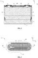
FIG. 2 is a cross sectional view of the secondary battery according to the present disclosure. -
FIG. 3 is a cross sectional view of an electrode unit ofFIG. 1 . -
FIG. 4 is a schematic view of a cap assembly ofFIG. 1 . -
FIG. 5 is a schematic view of an insulating member ofFIG. 4 . -
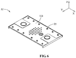
FIG. 6 is another schematic view of the insulating member ofFIG. 4 . - To make objects, technical solutions and advantages of the present disclosure more clear, the present disclosure will be further described hereinafter in detail in combination with the accompanying figures and the embodiments. It should be understood that the specific embodiments described herein are merely used to explain the present disclosure but are not intended to limit the present disclosure.
- In the description of the present disclosure, unless otherwise specifically defined and limited, the terms "first", "second" and "third" are only used for illustrative purposes and are not to be construed as expressing or implying a relative importance. The term "plurality" indicate two or more. Unless otherwise defined or described, the term "connect" or "fix" should be broadly interpreted, for example, the term "connect" can be "fixedly connect", "detachably connect", "integrally connect", "electrically connect" or "signal connect". The term "connect" also can be "directly connect" or "indirectly connect via a medium". For the persons skilled in the art, the specific meanings of the abovementioned terms in the present disclosure can be understood according to the specific situation.
- In the description of the present disclosure, it should be understood that spatially relative terms, such as "above", "below" and the like, are described based on orientations illustrated in the figures, but are not intended to limit the embodiments of the present disclosure.
- In the present disclosure, a battery module generally includes secondary batteries, end plates, side plates and busbars. The secondary batteries are provided as plurality in number and are arranged sequentially. The secondary battery of the present disclosure may be a prismatic lithium-ion battery. An arrangement direction of the secondary batteries is parallel to a width direction Y of each secondary battery. The end plates are provide as two in number and the two end plates are respectively provided at two ends of the secondary batteries in the arrange direction, and the side plates are provided as two in number and the two side plates are respectively provided at two sides of the secondary batteries. The end plates and the side plates are welded together to form a rectangular frame. The plurality of secondary batteries are fixed to the frame. The busbars connect the secondary batteries together in series, in parallel or in series-parallel.
- Hereinafter a secondary battery of the present disclosure will be described in detail.
- Referring to
FIG. 1 andFIG. 2 , the secondary battery in the present application includes an electrode assembly 1, acase 2 and acap assembly 3. - An
accommodating cavity 21 is formed in thecase 2 to receive the electrode assembly 1 and an electrolyte. An opening is formed at an end of thecase 2 in an axial direction Z, and the electrode assembly 1 can be placed into thecase 2 via the opening. Thecase 2 is made of a conductive metal material, such as aluminum, aluminum alloy or the like. The axial direction Z is parallel to an extending direction of theaccommodating cavity 21, and when used in a vehicle, thecap assembly 3 of the secondary battery is substantially parallel to the ground, and the axial direction Z is parallel to a height direction of the secondary battery, perpendicular to the width direction Y of the secondary battery, a length direction X of the secondary battery and the arrange direction of the secondary batteries. - The electrode assembly 1 includes a plurality of
electrode units 11, and the plurality ofelectrode units 11 are stacked in the axial direction Z of theaccommodating cavity 21. Referring toFIG. 3 , eachelectrode unit 11 includes afirst electrode plate 111, asecond electrode plate 112 and aseparator 113, and theseparator 113 separates thefirst electrode plate 111 and thesecond electrode plate 112. Theelectrode unit 11 is formed by spirally winding thefirst electrode plate 111, thesecond electrode plate 112 and theseparator 113, and theelectrode unit 11 may be pressed to a flat structure. Alternatively, eachelectrode unit 11 may be formed by stacking thefirst electrode plate 111, thesecond electrode plate 112 and theseparator 113. - The
first electrode plate 111 includes an aluminum foil and a positive active material coated on a surface of the aluminum foil, and the positive active material may include lithium manganese oxide or lithium iron phosphate. Thesecond electrode plate 112 includes a copper foil and a negative active material coated on a surface of the copper foil, and the negative active material may include graphite or silicon. - The
cap assembly 3 includes acap plate 31, an insulatingmember 32,electrode terminals 33 andcurrent collecting members 34. Thecap plate 31 is connected with thecase 2 and covers the opening of thecase 2, thereby sealing the electrode assembly 1 inside theaccommodating cavity 21 of thecase 2. The insulatingmember 32 is provided at an inner side of thecap plate 31, that is, the insulatingmember 32 is provided at a side of thecap plate 31 close to the electrode assembly 1. Theelectrode terminals 33 are provided to thecap plate 31 and protrude to outside of thecap plate 31. Both of theelectrode terminals 33 and thecurrent collecting members 34 are provided as two in number, one current collectingmember 34 connects thefirst electrode plate 111 and oneelectrode terminal 33, and the other current collectingmember 34 connects thesecond electrode plate 112 and theother electrode terminal 33. - The insulating
member 32 is positioned at a side of the electrode assembly 1 in the axial direction Z, that is, the insulatingmember 32 is positioned at an end of theelectrode units 11 in a stack direction of theelectrode units 11. The insulatingmember 32 is provided with afirst surface 321 at a side close to the electrode assembly 1, and thefirst surface 321 is a flat surface. In the present disclosure, thefirst surface 321 is substantially perpendicular to the axial direction Z. - In a charge process or a discharge process, each
electrode unit 11 will expand. In the present disclosure, the plurality ofelectrode units 11 of the secondary battery are stacked in the axial direction Z, so expansions of theelectrode units 11 will be accumulated in the axial direction Z. In the width direction Y, expansions of theelectrode units 11 is smaller, so the overall expansion amount of the electrode assembly 1 in the width direction Y is smaller, and correspondingly, an expanding force applied to thecase 2 by the electrode assembly 1 is smaller too. - In a battery module, an arrangement direction of the secondary batteries is perpendicular to the axial direction Z, so even though the expansions of all the electrode assemblies 1 are accumulated in the arrange direction, a resultant composite force will not be excessive, thereby preventing the secondary batteries being broken, and ensuring performance and life of the secondary batteries.
- In addition, in current technologies, the two end plates of the battery module are used to clamp the secondary batteries; in the case where the resultant force generated by expansions of the secondary batteries is excessive, it may lead to a welding position between the end plate and the side plate fracturing and result in failure of the battery module. In contrast, in the present disclosure, the resultant force generated by the secondary batteries when expanding is small, thereby avoiding failure of the battery module.
- In the secondary battery, when the
electrode units 11 expand, the expansions of the plurality ofelectrode units 11 will be accumulated in the axial direction Z, thereby leading to theelectrode unit 11 of the electrode assembly 1 closest to the insulatingmember 32 contacting thefirst surface 321 of the insulatingmember 32, and even pressing thefirst surface 321. If thefirst surface 321 is uneven, a force applied to theelectrode unit 11 by thefirst surface 321 is uneven too, thereby leading to serious local deformation of theelectrode unit 11, and resulting in fracturing of the electrode plates of theelectrode unit 11 and causing safety risk. In contrast, in the present disclosure, thefirst surface 321 is a flat surface, so when theelectrode units 11 expand, it can avoid uneven deformation of theelectrode unit 11, thereby preventing fracturing of the electrode plates, and thus safety performance can be improved. - Referring to
FIG. 3 , theelectrode unit 11 is a flat structure formed by winding, and a periphery of theelectrode unit 11 are formed with wide surfaces S1 and narrow surfaces S2. The wide surfaces S1 are provided as two in number and the two wide surfaces S1 are respectively positioned at two ends of theelectrode unit 11 in the axial direction Z, and the narrow surfaces S2 are provided as two in number and the two narrow surfaces S2 are respectively positioned at two ends of theelectrode unit 11 in the width direction Y. Each narrow surface S2 is in the shape of arc and connects the two wide surfaces S1. - The wide surface S1 of
electrode unit 11 at uppermost is disposed to face thefirst surface 321 in the axial direction Z. Before theelectrode unit 11 expands, the wide surface S1 is approximately parallel to thefirst surface 321. The wide surface S1 has a larger area, so when theelectrode unit 11 expands, the wide surface S1 and thefirst surface 321 facing each other are easier to contact evenly. - In the secondary battery, the plurality of
electrode units 11 are directly stacked in the axial direction Z. Every twoadjacent electrode units 11 contact each other via their respective wide surfaces S1. - A dimension of the
first surface 321 in the width direction Y is larger than a dimension of the wide surface S1 in the width direction Y. In this way, thefirst surface 321 can completely cover the wide surface S1 in the width direction Y, which ensures the even deformation of wide surface S1. Preferably, in the width direction Y, a midline of thefirst surface 321 is aligned with a midline of the wide surface S1 up and down. - The insulating
member 32 is made from an insulating material, such as plastic. When the electrode assembly 1 presses the insulatingmember 32, the insulatingmember 32 made from plastic can absorb the expanding force via deformation, thereby decreasing a reaction force applied to the electrode assembly 1 and avoiding the electrode plate being fractured. - If a Young's modulus of the insulating
member 32 is too high, the deformation ability of the insulatingmember 32 would be poor, and thus the insulatingmember 32 could not accommodate the expanding force effectively. Therefore, preferably, the Young's modulus of the insulatingmember 32 may ranges from 0.5Gpa to1.2Gpa. - A first buffer gap G1 is provided between the insulating
member 32 and the electrode assembly 1. When the electrode assembly 1 expands, the first buffer gap G1 can reserve a certain expanding space for the electrode assembly 1; in other words, the first buffer gap G1 can accommodate the expansion of the electrode assembly 1, thereby decreasing the expanding force applied to the insulatingmember 32 by the electrode assembly 1 and providing buffering. - Preferably, a height of the first buffer gap G1 in the axial direction Z may ranges from 0.5mm to 12mm. If the height of the first buffer gap G1 in the axial direction Z is too small, for example less than 0.5mm, the buffering effect of the first buffer gap G1 is limited, and the insulating
member 32 may still be subjected to a larger expanding force. If the height of the first buffer gap G1 in the axial direction Z is too large, for example larger than 12mm, it may lead to an excessive waste of the space and reduce an energy density of the secondary battery. - A second buffer gap G2 is provided between the
cap plate 31 and the insulatingmember 32. When the electrode assembly 1 presses the insulatingmember 32, the insulatingmember 32 can release the expanding force via deformation. By providing the second buffer gap G2, it can avoid that thecap plate 31 would limit the deformation of the insulatingmember 32, thereby providing buffering. Further, by providing the second buffer gap G2, it can decrease the expanding force transferred to thecap plate 31, thereby avoiding deformation of thecap plate 31. - Referring to
FIG. 6 , in the present disclosure, the second buffer gap G2 may be formed by providing asecond groove 323 in the insulatingmember 32. - The
cap plate 31 is fixedly connected with the insulatingmember 32 via connectingmembers 35. The connectingmembers 35 and the insulatingmember 32 may be formed integrally. The connectingmembers 35 are fixed to thecap plate 31 by thermal melting. If a flatness of thefirst surface 321 is too large, theelectrode unit 11 would deforms unevenly when thefirst surface 321 contacts theelectrode unit 11, resulting in fracturing of the electrode plates. Therefore, the flatness of thefirst surface 321 should not be larger than 0.6mm, preferably not larger than 0.3mm. - Referring to
FIG. 4 and FIG. 5 , the insulatingmember 32 is provided withfirst grooves 322 at a side close to the electrode assembly 1, a through-hole is provided on a bottom wall of thefirst groove 322. The current collectingmember 34 includes afirst portion 341, asecond portion 343 and athird portion 344. Thefirst portion 341 is accommodated in thefirst groove 322. Thesecond portion 343 is connected with thefirst portion 341 and extends into the through-hole of the insulatingmember 32, and thesecond portion 343 is fixed with theelectrode terminal 33. Thethird portion 344 bends downwardly from an end of thefirst portion 341 in the length direction X and is connected with the electrode assembly 1. In the present disclosure, by providing thefirst groove 322, it can decrease a space occupied by the current collectingmember 34 in the axial direction Z. - The
first portion 341 is provided with asecond surface 342 at a side close to the electrode assembly 1. When the electrode assembly 1 expands, the electrode assembly 1 may press thesecond surface 342; if thefirst surface 321 is misaligned with thesecond surface 342, the electrode assembly 1 would deform unevenly at a boundary between thefirst surface 321 and thesecond surface 342, which leads to fracturing of the electrode plates. Therefore, in the present disclosure, it is preferable that thesecond surface 342 is flush with thefirst surface 321.
| 1 |
34 |
| 11 |
341 |
| 111 |
342 |
| 112 |
343 |
| 113 |
344 |
| 2 |
35 connecting |
| 21 accommodating cavity | S1 |
| 3 cap assembly | S2 |
| 31 cap plate | G1 |
| 32 insulating member | G2 |
| 321 first surface | |
| 322 first groove | |
| 323 second groove | Z |
| 33 electrode terminal |
Claims (10)
- A secondary battery, comprising: an electrode assembly (1), a case (2) and a cap assembly (3), whereinthe case (2) comprises an accommodating cavity (21), the accommodating cavity (21) comprises an opening, and the electrode assembly (1) is accommodated in the accommodating cavity (21);the electrode assembly (1) comprises a plurality of electrode units (11), and the electrode units (11) are stacked in an axial direction (Z) of the accommodating cavity (21);the cap assembly (3) comprises a cap plate (31) and an insulating member (32) provided at an inner side of the cap plate (31), the cap plate (31) is connected with the case (2), and the insulating member (32) is positioned at a side of the electrode assembly (1) in the axial direction (Z); andthe insulating member (32) is provided with a first surface (321) at a side close to the electrode assembly (1), and the first surface (321) is a flat surface.
- The secondary battery according to claim 1, wherein the electrode unit (11) comprises a first electrode plate (111), a second electrode plate (112) and a separator (113) winded together, and comprises wide surfaces (S1) and narrow surfaces (S2);
the first surface (321) is disposed to face the wide surfaces (S1) in the axial direction (Z), every two adjacent electrode units (11) contact each other via respective wide surfaces (S1), and the narrow surfaces (S2) are connected with the wide surfaces (S1) and positioned at two ends of the electrode unit in a width direction (Y). - The secondary battery according to claim 2, wherein a dimension of the first surface (321) in the width direction (Y) is larger than a dimension of the wide surface (S1) in the width direction (Y).
- The secondary battery according to claim 1, wherein the insulating member (32) is made from plastic, and a Young's modulus of the insulating member (32) ranges from 0.5Gpa to 1.2Gpa.
- The secondary battery according to claim 1, wherein a first buffer gap (G1) is provided between the insulating member (32) and the electrode assembly (1), and is used to buffer expansive deformation of the electrode assembly (1).
- The secondary battery according to claim 5, wherein a height of the first buffer gap (G1) in the axial direction (Z) ranges from 0.5mm to 12mm.
- The secondary battery according to claim 1, wherein a second buffer gap (G2) is provided between the cap plate (31) and the insulating member (32), and the cap plate (31) and the insulating member (32) are fixedly connected via connecting members (35).
- The secondary battery according to claim 1, wherein a flatness of the first surface (321) is not larger than 0.6mm.
- The secondary battery according to clam 1, whereinthe cap assembly (3) further comprises electrode terminals (33) and current collecting members (34), the electrode terminals (33) are provided to the cap plate (31), and the current collecting members (34) connect the electrode terminals (33) and the electrode assembly (1);the insulating member (32) is provided with a first groove (341) at a side close to the electrode assembly (1),the current collecting member (34) comprises a first portion (341) accommodated in the first groove (332); andthe first portion (341) is provided with a second surface at a side close to the electrode assembly (1), and the second surface (342) is flush with the first surface (321).
- A battery module, comprising a plurality of the secondary batteries according to any one of claims 1 to 9, wherein the plurality of secondary batteries are arranged sequentially, and an arrangement direction of the plurality of secondary batteries is perpendicular to the axial direction (Z).
Applications Claiming Priority (2)
| Application Number | Priority Date | Filing Date | Title |
|---|---|---|---|
| CN201822269878.1U CN209401756U (en) | 2018-12-29 | 2018-12-29 | Secondary batteries and battery modules |
| PCT/CN2019/075826 WO2020133661A1 (en) | 2018-12-29 | 2019-02-22 | Secondary battery and battery module |
Publications (3)
| Publication Number | Publication Date |
|---|---|
| EP3883033A1 true EP3883033A1 (en) | 2021-09-22 |
| EP3883033A4 EP3883033A4 (en) | 2022-01-12 |
| EP3883033B1 EP3883033B1 (en) | 2024-03-13 |
Family
ID=67897316
Family Applications (1)
| Application Number | Title | Priority Date | Filing Date |
|---|---|---|---|
| EP19903839.9A Active EP3883033B1 (en) | 2018-12-29 | 2019-02-22 | Secondary battery and battery module |
Country Status (5)
| Country | Link |
|---|---|
| US (1) | US11476526B2 (en) |
| EP (1) | EP3883033B1 (en) |
| CN (1) | CN209401756U (en) |
| HU (1) | HUE066480T2 (en) |
| WO (1) | WO2020133661A1 (en) |
Families Citing this family (6)
| Publication number | Priority date | Publication date | Assignee | Title |
|---|---|---|---|---|
| CN111384351B (en) * | 2018-12-29 | 2024-10-01 | 宁德时代新能源科技股份有限公司 | Secondary battery and battery module |
| CN113644354A (en) * | 2021-07-15 | 2021-11-12 | 东莞塔菲尔新能源科技有限公司 | Battery top cap structure, battery and electric device |
| CN115842223B (en) * | 2021-10-08 | 2024-10-18 | 宁德时代新能源科技股份有限公司 | Battery monomer, battery and power consumption device |
| CN116670897B (en) * | 2021-10-20 | 2025-07-29 | 宁德时代新能源科技股份有限公司 | Battery cell, manufacturing method and manufacturing system thereof, battery and electricity utilization device |
| CN117832780A (en) * | 2022-09-27 | 2024-04-05 | 厦门海辰储能科技股份有限公司 | Plastics, batteries, battery modules and electrical equipment |
| EP4376178B1 (en) * | 2022-09-27 | 2026-04-29 | Hithium Tech HK Limited | Bottom plastic and battery having same |
Family Cites Families (15)
| Publication number | Priority date | Publication date | Assignee | Title |
|---|---|---|---|---|
| CN1732587B (en) * | 2002-12-27 | 2010-10-06 | 松下电器产业株式会社 | Electrochemical element and its manufacturing method |
| JP4906538B2 (en) * | 2007-02-28 | 2012-03-28 | 日立ビークルエナジー株式会社 | Lithium secondary battery |
| KR101077873B1 (en) * | 2007-06-22 | 2011-10-31 | 주식회사 엘지화학 | Case for Secondary Battery Having Improved Safety and Lithium Secondary Battery Containing the Same |
| JP5699559B2 (en) * | 2010-11-17 | 2015-04-15 | ソニー株式会社 | Non-aqueous electrolyte battery |
| EP2897194A4 (en) * | 2012-09-11 | 2016-08-10 | Routejade Inc | STACKED SECONDARY BATTERY |
| US9496588B2 (en) * | 2013-07-30 | 2016-11-15 | Johnson Controls Technology Company | Battery module with cooling features |
| KR102415884B1 (en) * | 2015-11-02 | 2022-07-04 | 에스케이온 주식회사 | Secondary battery |
| CN105609882B (en) * | 2016-03-18 | 2024-06-04 | 东莞烯谷新能源科技有限公司 | Internal multi-core stack energy storage device |
| JP7049603B2 (en) * | 2016-05-23 | 2022-04-07 | 株式会社Gsユアサ | A power storage element, a power storage device including a power storage element, a mobile body including a power storage element, and a power storage system including a power storage element. |
| WO2017208534A1 (en) * | 2016-05-31 | 2017-12-07 | 株式会社村田製作所 | Secondary battery |
| JP6780419B2 (en) * | 2016-09-30 | 2020-11-04 | 株式会社Gsユアサ | Power storage element |
| CN207800658U (en) * | 2018-01-02 | 2018-08-31 | 泉州艾尼维亚日用品有限公司 | A kind of lithium-ion-power cell head cover |
| KR102611657B1 (en) * | 2018-01-29 | 2023-12-08 | 삼성에스디아이 주식회사 | Secondary Battery |
| CN207896132U (en) * | 2018-02-12 | 2018-09-21 | 芜湖天弋能源科技有限公司 | Power battery head cover safety device |
| CN108461665A (en) * | 2018-05-31 | 2018-08-28 | 东莞百思利新能源科技有限公司 | Secondary battery top cap and secondary battery thereof |
-
2018
- 2018-12-29 CN CN201822269878.1U patent/CN209401756U/en active Active
-
2019
- 2019-02-22 EP EP19903839.9A patent/EP3883033B1/en active Active
- 2019-02-22 WO PCT/CN2019/075826 patent/WO2020133661A1/en not_active Ceased
- 2019-02-22 HU HUE19903839A patent/HUE066480T2/en unknown
-
2020
- 2020-06-02 US US16/890,457 patent/US11476526B2/en active Active
Also Published As
| Publication number | Publication date |
|---|---|
| HUE066480T2 (en) | 2024-08-28 |
| EP3883033B1 (en) | 2024-03-13 |
| US20200295317A1 (en) | 2020-09-17 |
| CN209401756U (en) | 2019-09-17 |
| WO2020133661A1 (en) | 2020-07-02 |
| US11476526B2 (en) | 2022-10-18 |
| EP3883033A4 (en) | 2022-01-12 |
Similar Documents
| Publication | Publication Date | Title |
|---|---|---|
| US11476526B2 (en) | Secondary battery, battery module and vehicle | |
| EP3678208B1 (en) | Battery module, battery pack, and vehicle | |
| US9203065B2 (en) | Battery module | |
| US12244025B2 (en) | Secondary battery and battery module | |
| EP3800689B1 (en) | Secondary battery, battery module and electric vehicle | |
| EP4087024A1 (en) | Battery, battery pack and electric vehicle | |
| EP1901365B1 (en) | Battery cell with small groove at surface and battery pack including the same | |
| CN209786120U (en) | Secondary batteries and battery modules | |
| EP3890085A1 (en) | Battery cell assembly, battery module and battery pack | |
| US11652233B2 (en) | Battery pack | |
| JP7471433B2 (en) | BATTERY, BATTERY MODULE, BATTERY PACK, AND ELECTRIC VEHICLE | |
| EP3800696B1 (en) | Secondary battery, battery module and electric vehicle | |
| EP4280357A1 (en) | Battery pack, method of assembling battery pack and battery cluster | |
| CN209183613U (en) | Secondary batteries and battery modules | |
| CN111384326B (en) | Secondary batteries and battery modules | |
| KR100637505B1 (en) | Electrode plate of secondary battery, manufacturing method thereof and secondary battery using this electrode plate | |
| JPH1145689A (en) | Package type battery device | |
| CN209401762U (en) | Secondary batteries and battery modules | |
| EP3937272A1 (en) | Electrochemical cell module | |
| WO2023116539A1 (en) | Battery and electrical apparatus | |
| CN223006881U (en) | Battery pack and electricity utilization device | |
| CN220042223U (en) | Extraction type blade cell | |
| US20230085917A1 (en) | Power storage module | |
| KR100667952B1 (en) | Secondary battery | |
| KR20250106814A (en) | Battery assembly and battery pack including the same |
Legal Events
| Date | Code | Title | Description |
|---|---|---|---|
| STAA | Information on the status of an ep patent application or granted ep patent |
Free format text: STATUS: THE INTERNATIONAL PUBLICATION HAS BEEN MADE |
|
| PUAI | Public reference made under article 153(3) epc to a published international application that has entered the european phase |
Free format text: ORIGINAL CODE: 0009012 |
|
| STAA | Information on the status of an ep patent application or granted ep patent |
Free format text: STATUS: REQUEST FOR EXAMINATION WAS MADE |
|
| 17P | Request for examination filed |
Effective date: 20210615 |
|
| AK | Designated contracting states |
Kind code of ref document: A1 Designated state(s): AL AT BE BG CH CY CZ DE DK EE ES FI FR GB GR HR HU IE IS IT LI LT LU LV MC MK MT NL NO PL PT RO RS SE SI SK SM TR |
|
| A4 | Supplementary search report drawn up and despatched |
Effective date: 20211213 |
|
| RIC1 | Information provided on ipc code assigned before grant |
Ipc: H01M 10/04 20060101AFI20211207BHEP |
|
| DAV | Request for validation of the european patent (deleted) | ||
| DAX | Request for extension of the european patent (deleted) | ||
| STAA | Information on the status of an ep patent application or granted ep patent |
Free format text: STATUS: EXAMINATION IS IN PROGRESS |
|
| 17Q | First examination report despatched |
Effective date: 20230119 |
|
| GRAP | Despatch of communication of intention to grant a patent |
Free format text: ORIGINAL CODE: EPIDOSNIGR1 |
|
| STAA | Information on the status of an ep patent application or granted ep patent |
Free format text: STATUS: GRANT OF PATENT IS INTENDED |
|
| INTG | Intention to grant announced |
Effective date: 20231023 |
|
| GRAS | Grant fee paid |
Free format text: ORIGINAL CODE: EPIDOSNIGR3 |
|
| GRAA | (expected) grant |
Free format text: ORIGINAL CODE: 0009210 |
|
| STAA | Information on the status of an ep patent application or granted ep patent |
Free format text: STATUS: THE PATENT HAS BEEN GRANTED |
|
| AK | Designated contracting states |
Kind code of ref document: B1 Designated state(s): AL AT BE BG CH CY CZ DE DK EE ES FI FR GB GR HR HU IE IS IT LI LT LU LV MC MK MT NL NO PL PT RO RS SE SI SK SM TR |
|
| P01 | Opt-out of the competence of the unified patent court (upc) registered |
Effective date: 20240204 |
|
| REG | Reference to a national code |
Ref country code: GB Ref legal event code: FG4D |
|
| REG | Reference to a national code |
Ref country code: CH Ref legal event code: EP |
|
| RAP4 | Party data changed (patent owner data changed or rights of a patent transferred) |
Owner name: CONTEMPORARY AMPEREX TECHNOLOGY CO., LIMITED |
|
| REG | Reference to a national code |
Ref country code: DE Ref legal event code: R096 Ref document number: 602019048427 Country of ref document: DE |
|
| REG | Reference to a national code |
Ref country code: IE Ref legal event code: FG4D |
|
| PG25 | Lapsed in a contracting state [announced via postgrant information from national office to epo] |
Ref country code: LT Free format text: LAPSE BECAUSE OF FAILURE TO SUBMIT A TRANSLATION OF THE DESCRIPTION OR TO PAY THE FEE WITHIN THE PRESCRIBED TIME-LIMIT Effective date: 20240313 |
|
| REG | Reference to a national code |
Ref country code: LT Ref legal event code: MG9D |
|
| PG25 | Lapsed in a contracting state [announced via postgrant information from national office to epo] |
Ref country code: GR Free format text: LAPSE BECAUSE OF FAILURE TO SUBMIT A TRANSLATION OF THE DESCRIPTION OR TO PAY THE FEE WITHIN THE PRESCRIBED TIME-LIMIT Effective date: 20240614 |
|
| REG | Reference to a national code |
Ref country code: NL Ref legal event code: MP Effective date: 20240313 |
|
| PG25 | Lapsed in a contracting state [announced via postgrant information from national office to epo] |
Ref country code: RS Free format text: LAPSE BECAUSE OF FAILURE TO SUBMIT A TRANSLATION OF THE DESCRIPTION OR TO PAY THE FEE WITHIN THE PRESCRIBED TIME-LIMIT Effective date: 20240613 Ref country code: HR Free format text: LAPSE BECAUSE OF FAILURE TO SUBMIT A TRANSLATION OF THE DESCRIPTION OR TO PAY THE FEE WITHIN THE PRESCRIBED TIME-LIMIT Effective date: 20240313 |
|
| PG25 | Lapsed in a contracting state [announced via postgrant information from national office to epo] |
Ref country code: ES Free format text: LAPSE BECAUSE OF FAILURE TO SUBMIT A TRANSLATION OF THE DESCRIPTION OR TO PAY THE FEE WITHIN THE PRESCRIBED TIME-LIMIT Effective date: 20240313 |
|
| PG25 | Lapsed in a contracting state [announced via postgrant information from national office to epo] |
Ref country code: RS Free format text: LAPSE BECAUSE OF FAILURE TO SUBMIT A TRANSLATION OF THE DESCRIPTION OR TO PAY THE FEE WITHIN THE PRESCRIBED TIME-LIMIT Effective date: 20240613 Ref country code: NO Free format text: LAPSE BECAUSE OF FAILURE TO SUBMIT A TRANSLATION OF THE DESCRIPTION OR TO PAY THE FEE WITHIN THE PRESCRIBED TIME-LIMIT Effective date: 20240613 Ref country code: LT Free format text: LAPSE BECAUSE OF FAILURE TO SUBMIT A TRANSLATION OF THE DESCRIPTION OR TO PAY THE FEE WITHIN THE PRESCRIBED TIME-LIMIT Effective date: 20240313 Ref country code: HR Free format text: LAPSE BECAUSE OF FAILURE TO SUBMIT A TRANSLATION OF THE DESCRIPTION OR TO PAY THE FEE WITHIN THE PRESCRIBED TIME-LIMIT Effective date: 20240313 Ref country code: GR Free format text: LAPSE BECAUSE OF FAILURE TO SUBMIT A TRANSLATION OF THE DESCRIPTION OR TO PAY THE FEE WITHIN THE PRESCRIBED TIME-LIMIT Effective date: 20240614 Ref country code: FI Free format text: LAPSE BECAUSE OF FAILURE TO SUBMIT A TRANSLATION OF THE DESCRIPTION OR TO PAY THE FEE WITHIN THE PRESCRIBED TIME-LIMIT Effective date: 20240313 Ref country code: ES Free format text: LAPSE BECAUSE OF FAILURE TO SUBMIT A TRANSLATION OF THE DESCRIPTION OR TO PAY THE FEE WITHIN THE PRESCRIBED TIME-LIMIT Effective date: 20240313 Ref country code: BG Free format text: LAPSE BECAUSE OF FAILURE TO SUBMIT A TRANSLATION OF THE DESCRIPTION OR TO PAY THE FEE WITHIN THE PRESCRIBED TIME-LIMIT Effective date: 20240313 |
|
| REG | Reference to a national code |
Ref country code: DE Ref legal event code: R081 Ref document number: 602019048427 Country of ref document: DE Owner name: CONTEMPORARY AMPEREX TECHNOLOGY (HONG KONG) LI, HK Free format text: FORMER OWNER: CONTEMPORARY AMPEREX TECHNOLOGY CO., LIMITED, NINGDE, FUJIAN, CN |
|
| REG | Reference to a national code |
Ref country code: AT Ref legal event code: MK05 Ref document number: 1666610 Country of ref document: AT Kind code of ref document: T Effective date: 20240313 |
|
| REG | Reference to a national code |
Ref country code: HU Ref legal event code: AG4A Ref document number: E066480 Country of ref document: HU |
|
| PG25 | Lapsed in a contracting state [announced via postgrant information from national office to epo] |
Ref country code: SE Free format text: LAPSE BECAUSE OF FAILURE TO SUBMIT A TRANSLATION OF THE DESCRIPTION OR TO PAY THE FEE WITHIN THE PRESCRIBED TIME-LIMIT Effective date: 20240313 Ref country code: LV Free format text: LAPSE BECAUSE OF FAILURE TO SUBMIT A TRANSLATION OF THE DESCRIPTION OR TO PAY THE FEE WITHIN THE PRESCRIBED TIME-LIMIT Effective date: 20240313 |
|
| PG25 | Lapsed in a contracting state [announced via postgrant information from national office to epo] |
Ref country code: NL Free format text: LAPSE BECAUSE OF FAILURE TO SUBMIT A TRANSLATION OF THE DESCRIPTION OR TO PAY THE FEE WITHIN THE PRESCRIBED TIME-LIMIT Effective date: 20240313 |
|
| REG | Reference to a national code |
Ref country code: GB Ref legal event code: 732E Free format text: REGISTERED BETWEEN 20240829 AND 20240904 |
|
| REG | Reference to a national code |
Ref country code: HU Ref legal event code: GB9C Owner name: CONTEMPORARY AMPEREX TECHNOLOGY (HONG KONG) LIMITED, HK Free format text: FORMER OWNER(S): CONTEMPORARY AMPEREX TECHNOLOGY CO., LIMITED, CN Ref country code: HU Ref legal event code: FH1C Free format text: FORMER REPRESENTATIVE(S): DANUBIA SZABADALMI ES JOGI IRODA KFT., HU Representative=s name: DANUBIA SZABADALMI ES JOGI IRODA KFT., HU |
|
| PG25 | Lapsed in a contracting state [announced via postgrant information from national office to epo] |
Ref country code: NL Free format text: LAPSE BECAUSE OF FAILURE TO SUBMIT A TRANSLATION OF THE DESCRIPTION OR TO PAY THE FEE WITHIN THE PRESCRIBED TIME-LIMIT Effective date: 20240313 |
|
| RAP2 | Party data changed (patent owner data changed or rights of a patent transferred) |
Owner name: CONTEMPORARY AMPEREX TECHNOLOGY(HONG KONG) LIMITED |
|
| PG25 | Lapsed in a contracting state [announced via postgrant information from national office to epo] |
Ref country code: IS Free format text: LAPSE BECAUSE OF FAILURE TO SUBMIT A TRANSLATION OF THE DESCRIPTION OR TO PAY THE FEE WITHIN THE PRESCRIBED TIME-LIMIT Effective date: 20240713 |
|
| PG25 | Lapsed in a contracting state [announced via postgrant information from national office to epo] |
Ref country code: SM Free format text: LAPSE BECAUSE OF FAILURE TO SUBMIT A TRANSLATION OF THE DESCRIPTION OR TO PAY THE FEE WITHIN THE PRESCRIBED TIME-LIMIT Effective date: 20240313 Ref country code: PT Free format text: LAPSE BECAUSE OF FAILURE TO SUBMIT A TRANSLATION OF THE DESCRIPTION OR TO PAY THE FEE WITHIN THE PRESCRIBED TIME-LIMIT Effective date: 20240715 |
|
| PG25 | Lapsed in a contracting state [announced via postgrant information from national office to epo] |
Ref country code: CZ Free format text: LAPSE BECAUSE OF FAILURE TO SUBMIT A TRANSLATION OF THE DESCRIPTION OR TO PAY THE FEE WITHIN THE PRESCRIBED TIME-LIMIT Effective date: 20240313 Ref country code: EE Free format text: LAPSE BECAUSE OF FAILURE TO SUBMIT A TRANSLATION OF THE DESCRIPTION OR TO PAY THE FEE WITHIN THE PRESCRIBED TIME-LIMIT Effective date: 20240313 |
|
| PG25 | Lapsed in a contracting state [announced via postgrant information from national office to epo] |
Ref country code: AT Free format text: LAPSE BECAUSE OF FAILURE TO SUBMIT A TRANSLATION OF THE DESCRIPTION OR TO PAY THE FEE WITHIN THE PRESCRIBED TIME-LIMIT Effective date: 20240313 |
|
| PG25 | Lapsed in a contracting state [announced via postgrant information from national office to epo] |
Ref country code: PL Free format text: LAPSE BECAUSE OF FAILURE TO SUBMIT A TRANSLATION OF THE DESCRIPTION OR TO PAY THE FEE WITHIN THE PRESCRIBED TIME-LIMIT Effective date: 20240313 |
|
| PG25 | Lapsed in a contracting state [announced via postgrant information from national office to epo] |
Ref country code: SK Free format text: LAPSE BECAUSE OF FAILURE TO SUBMIT A TRANSLATION OF THE DESCRIPTION OR TO PAY THE FEE WITHIN THE PRESCRIBED TIME-LIMIT Effective date: 20240313 |
|
| PG25 | Lapsed in a contracting state [announced via postgrant information from national office to epo] |
Ref country code: SM Free format text: LAPSE BECAUSE OF FAILURE TO SUBMIT A TRANSLATION OF THE DESCRIPTION OR TO PAY THE FEE WITHIN THE PRESCRIBED TIME-LIMIT Effective date: 20240313 Ref country code: SK Free format text: LAPSE BECAUSE OF FAILURE TO SUBMIT A TRANSLATION OF THE DESCRIPTION OR TO PAY THE FEE WITHIN THE PRESCRIBED TIME-LIMIT Effective date: 20240313 Ref country code: RO Free format text: LAPSE BECAUSE OF FAILURE TO SUBMIT A TRANSLATION OF THE DESCRIPTION OR TO PAY THE FEE WITHIN THE PRESCRIBED TIME-LIMIT Effective date: 20240313 Ref country code: PT Free format text: LAPSE BECAUSE OF FAILURE TO SUBMIT A TRANSLATION OF THE DESCRIPTION OR TO PAY THE FEE WITHIN THE PRESCRIBED TIME-LIMIT Effective date: 20240715 Ref country code: PL Free format text: LAPSE BECAUSE OF FAILURE TO SUBMIT A TRANSLATION OF THE DESCRIPTION OR TO PAY THE FEE WITHIN THE PRESCRIBED TIME-LIMIT Effective date: 20240313 Ref country code: IS Free format text: LAPSE BECAUSE OF FAILURE TO SUBMIT A TRANSLATION OF THE DESCRIPTION OR TO PAY THE FEE WITHIN THE PRESCRIBED TIME-LIMIT Effective date: 20240713 Ref country code: EE Free format text: LAPSE BECAUSE OF FAILURE TO SUBMIT A TRANSLATION OF THE DESCRIPTION OR TO PAY THE FEE WITHIN THE PRESCRIBED TIME-LIMIT Effective date: 20240313 Ref country code: CZ Free format text: LAPSE BECAUSE OF FAILURE TO SUBMIT A TRANSLATION OF THE DESCRIPTION OR TO PAY THE FEE WITHIN THE PRESCRIBED TIME-LIMIT Effective date: 20240313 Ref country code: AT Free format text: LAPSE BECAUSE OF FAILURE TO SUBMIT A TRANSLATION OF THE DESCRIPTION OR TO PAY THE FEE WITHIN THE PRESCRIBED TIME-LIMIT Effective date: 20240313 |
|
| PG25 | Lapsed in a contracting state [announced via postgrant information from national office to epo] |
Ref country code: IT Free format text: LAPSE BECAUSE OF FAILURE TO SUBMIT A TRANSLATION OF THE DESCRIPTION OR TO PAY THE FEE WITHIN THE PRESCRIBED TIME-LIMIT Effective date: 20240313 |
|
| REG | Reference to a national code |
Ref country code: DE Ref legal event code: R097 Ref document number: 602019048427 Country of ref document: DE |
|
| PG25 | Lapsed in a contracting state [announced via postgrant information from national office to epo] |
Ref country code: IT Free format text: LAPSE BECAUSE OF FAILURE TO SUBMIT A TRANSLATION OF THE DESCRIPTION OR TO PAY THE FEE WITHIN THE PRESCRIBED TIME-LIMIT Effective date: 20240313 |
|
| PG25 | Lapsed in a contracting state [announced via postgrant information from national office to epo] |
Ref country code: DK Free format text: LAPSE BECAUSE OF FAILURE TO SUBMIT A TRANSLATION OF THE DESCRIPTION OR TO PAY THE FEE WITHIN THE PRESCRIBED TIME-LIMIT Effective date: 20240313 |
|
| PLBE | No opposition filed within time limit |
Free format text: ORIGINAL CODE: 0009261 |
|
| STAA | Information on the status of an ep patent application or granted ep patent |
Free format text: STATUS: NO OPPOSITION FILED WITHIN TIME LIMIT |
|
| PG25 | Lapsed in a contracting state [announced via postgrant information from national office to epo] |
Ref country code: DK Free format text: LAPSE BECAUSE OF FAILURE TO SUBMIT A TRANSLATION OF THE DESCRIPTION OR TO PAY THE FEE WITHIN THE PRESCRIBED TIME-LIMIT Effective date: 20240313 |
|
| 26N | No opposition filed |
Effective date: 20241216 |
|
| PG25 | Lapsed in a contracting state [announced via postgrant information from national office to epo] |
Ref country code: SI Free format text: LAPSE BECAUSE OF FAILURE TO SUBMIT A TRANSLATION OF THE DESCRIPTION OR TO PAY THE FEE WITHIN THE PRESCRIBED TIME-LIMIT Effective date: 20240313 |
|
| PG25 | Lapsed in a contracting state [announced via postgrant information from national office to epo] |
Ref country code: MC Free format text: LAPSE BECAUSE OF FAILURE TO SUBMIT A TRANSLATION OF THE DESCRIPTION OR TO PAY THE FEE WITHIN THE PRESCRIBED TIME-LIMIT Effective date: 20240313 |
|
| REG | Reference to a national code |
Ref country code: CH Ref legal event code: PL |
|
| PG25 | Lapsed in a contracting state [announced via postgrant information from national office to epo] |
Ref country code: LU Free format text: LAPSE BECAUSE OF NON-PAYMENT OF DUE FEES Effective date: 20250222 |
|
| PG25 | Lapsed in a contracting state [announced via postgrant information from national office to epo] |
Ref country code: CH Free format text: LAPSE BECAUSE OF NON-PAYMENT OF DUE FEES Effective date: 20250228 |
|
| REG | Reference to a national code |
Ref country code: BE Ref legal event code: MM Effective date: 20250228 |
|
| PG25 | Lapsed in a contracting state [announced via postgrant information from national office to epo] |
Ref country code: BE Free format text: LAPSE BECAUSE OF NON-PAYMENT OF DUE FEES Effective date: 20250228 |
|
| PG25 | Lapsed in a contracting state [announced via postgrant information from national office to epo] |
Ref country code: IE Free format text: LAPSE BECAUSE OF NON-PAYMENT OF DUE FEES Effective date: 20250222 |
|
| PGFP | Annual fee paid to national office [announced via postgrant information from national office to epo] |
Ref country code: HU Payment date: 20260211 Year of fee payment: 8 |
|
| PGFP | Annual fee paid to national office [announced via postgrant information from national office to epo] |
Ref country code: GB Payment date: 20260224 Year of fee payment: 8 |
|
| PGFP | Annual fee paid to national office [announced via postgrant information from national office to epo] |
Ref country code: DE Payment date: 20260223 Year of fee payment: 8 |
|
| PGFP | Annual fee paid to national office [announced via postgrant information from national office to epo] |
Ref country code: FR Payment date: 20260224 Year of fee payment: 8 |