EP3883012A1 - Battery, battery pack, vehicle, and stationary power supply - Google Patents
Battery, battery pack, vehicle, and stationary power supply Download PDFInfo
- Publication number
- EP3883012A1 EP3883012A1 EP20193368.6A EP20193368A EP3883012A1 EP 3883012 A1 EP3883012 A1 EP 3883012A1 EP 20193368 A EP20193368 A EP 20193368A EP 3883012 A1 EP3883012 A1 EP 3883012A1
- Authority
- EP
- European Patent Office
- Prior art keywords
- aqueous electrolyte
- battery
- licl
- 9mol
- negative electrode
- Prior art date
- Legal status (The legal status is an assumption and is not a legal conclusion. Google has not performed a legal analysis and makes no representation as to the accuracy of the status listed.)
- Pending
Links
- 239000003792 electrolyte Substances 0.000 claims abstract description 489
- 230000003204 osmotic effect Effects 0.000 claims abstract description 88
- 150000003839 salts Chemical class 0.000 claims abstract description 67
- 239000002131 composite material Substances 0.000 claims description 50
- 230000035699 permeability Effects 0.000 claims description 34
- 239000007773 negative electrode material Substances 0.000 claims description 31
- 239000000872 buffer Substances 0.000 claims description 30
- 239000003795 chemical substances by application Substances 0.000 claims description 25
- GWEVSGVZZGPLCZ-UHFFFAOYSA-N Titan oxide Chemical compound O=[Ti]=O GWEVSGVZZGPLCZ-UHFFFAOYSA-N 0.000 claims description 16
- 230000001681 protective effect Effects 0.000 claims description 16
- 239000002253 acid Substances 0.000 claims description 12
- OGIDPMRJRNCKJF-UHFFFAOYSA-N titanium oxide Inorganic materials [Ti]=O OGIDPMRJRNCKJF-UHFFFAOYSA-N 0.000 claims description 12
- FDLZQPXZHIFURF-UHFFFAOYSA-N [O-2].[Ti+4].[Li+] Chemical compound [O-2].[Ti+4].[Li+] FDLZQPXZHIFURF-UHFFFAOYSA-N 0.000 claims description 11
- 238000009826 distribution Methods 0.000 claims description 11
- 230000001172 regenerating effect Effects 0.000 claims description 10
- 238000010494 dissociation reaction Methods 0.000 claims description 5
- 230000005593 dissociations Effects 0.000 claims description 5
- SWAIALBIBWIKKQ-UHFFFAOYSA-N lithium titanium Chemical compound [Li].[Ti] SWAIALBIBWIKKQ-UHFFFAOYSA-N 0.000 claims description 5
- 238000013459 approach Methods 0.000 abstract description 84
- KWGKDLIKAYFUFQ-UHFFFAOYSA-M lithium chloride Chemical compound [Li+].[Cl-] KWGKDLIKAYFUFQ-UHFFFAOYSA-M 0.000 description 444
- 239000007784 solid electrolyte Substances 0.000 description 78
- 239000012528 membrane Substances 0.000 description 66
- 239000002245 particle Substances 0.000 description 62
- XLYOFNOQVPJJNP-UHFFFAOYSA-N water Substances O XLYOFNOQVPJJNP-UHFFFAOYSA-N 0.000 description 55
- INHCSSUBVCNVSK-UHFFFAOYSA-L lithium sulfate Chemical compound [Li+].[Li+].[O-]S([O-])(=O)=O INHCSSUBVCNVSK-UHFFFAOYSA-L 0.000 description 50
- 239000002861 polymer material Substances 0.000 description 49
- -1 carbonate compound Chemical class 0.000 description 46
- 239000000178 monomer Substances 0.000 description 33
- 229910003480 inorganic solid Inorganic materials 0.000 description 32
- 238000005259 measurement Methods 0.000 description 32
- 229910052751 metal Inorganic materials 0.000 description 32
- 239000002184 metal Substances 0.000 description 32
- 239000010410 layer Substances 0.000 description 30
- 238000002156 mixing Methods 0.000 description 29
- 210000004027 cell Anatomy 0.000 description 26
- KRKNYBCHXYNGOX-UHFFFAOYSA-N citric acid Chemical compound OC(=O)CC(O)(C(O)=O)CC(O)=O KRKNYBCHXYNGOX-UHFFFAOYSA-N 0.000 description 21
- 239000006258 conductive agent Substances 0.000 description 21
- 239000011230 binding agent Substances 0.000 description 19
- 238000003860 storage Methods 0.000 description 19
- NBIIXXVUZAFLBC-UHFFFAOYSA-N Phosphoric acid Chemical compound OP(O)(O)=O NBIIXXVUZAFLBC-UHFFFAOYSA-N 0.000 description 18
- 150000001875 compounds Chemical group 0.000 description 18
- 229910001416 lithium ion Inorganic materials 0.000 description 18
- KDYFGRWQOYBRFD-UHFFFAOYSA-N Succinic acid Natural products OC(=O)CCC(O)=O KDYFGRWQOYBRFD-UHFFFAOYSA-N 0.000 description 17
- 238000006243 chemical reaction Methods 0.000 description 17
- 239000007789 gas Substances 0.000 description 17
- 239000007774 positive electrode material Substances 0.000 description 17
- 150000001450 anions Chemical class 0.000 description 16
- 150000002500 ions Chemical class 0.000 description 16
- 239000000203 mixture Substances 0.000 description 16
- 229910003473 lithium bis(trifluoromethanesulfonyl)imide Inorganic materials 0.000 description 15
- QSZMZKBZAYQGRS-UHFFFAOYSA-N lithium;bis(trifluoromethylsulfonyl)azanide Chemical compound [Li+].FC(F)(F)S(=O)(=O)[N-]S(=O)(=O)C(F)(F)F QSZMZKBZAYQGRS-UHFFFAOYSA-N 0.000 description 15
- 238000000034 method Methods 0.000 description 15
- UFHFLCQGNIYNRP-UHFFFAOYSA-N Hydrogen Chemical compound [H][H] UFHFLCQGNIYNRP-UHFFFAOYSA-N 0.000 description 13
- 238000005470 impregnation Methods 0.000 description 13
- 239000002002 slurry Substances 0.000 description 13
- 238000004891 communication Methods 0.000 description 12
- 238000005868 electrolysis reaction Methods 0.000 description 12
- 125000000524 functional group Chemical group 0.000 description 12
- 239000001257 hydrogen Substances 0.000 description 12
- 229910052739 hydrogen Inorganic materials 0.000 description 12
- 239000002904 solvent Substances 0.000 description 12
- 239000010936 titanium Substances 0.000 description 12
- 238000010521 absorption reaction Methods 0.000 description 11
- 239000011149 active material Substances 0.000 description 11
- 230000000052 comparative effect Effects 0.000 description 11
- 239000011888 foil Substances 0.000 description 11
- 239000011133 lead Substances 0.000 description 11
- 238000006722 reduction reaction Methods 0.000 description 11
- IJGRMHOSHXDMSA-UHFFFAOYSA-N Atomic nitrogen Chemical compound N#N IJGRMHOSHXDMSA-UHFFFAOYSA-N 0.000 description 10
- 229910052782 aluminium Inorganic materials 0.000 description 10
- XEEYBQQBJWHFJM-UHFFFAOYSA-N iron Substances [Fe] XEEYBQQBJWHFJM-UHFFFAOYSA-N 0.000 description 10
- 229920002037 poly(vinyl butyral) polymer Polymers 0.000 description 10
- 239000011734 sodium Substances 0.000 description 10
- 239000010935 stainless steel Substances 0.000 description 10
- 229910001220 stainless steel Inorganic materials 0.000 description 10
- QTBSBXVTEAMEQO-UHFFFAOYSA-N Acetic acid Chemical compound CC(O)=O QTBSBXVTEAMEQO-UHFFFAOYSA-N 0.000 description 9
- 238000005481 NMR spectroscopy Methods 0.000 description 9
- PXHVJJICTQNCMI-UHFFFAOYSA-N Nickel Chemical compound [Ni] PXHVJJICTQNCMI-UHFFFAOYSA-N 0.000 description 9
- 239000002033 PVDF binder Substances 0.000 description 9
- 229910000147 aluminium phosphate Inorganic materials 0.000 description 9
- 239000007788 liquid Substances 0.000 description 9
- 239000000463 material Substances 0.000 description 9
- 238000007254 oxidation reaction Methods 0.000 description 9
- 229920002981 polyvinylidene fluoride Polymers 0.000 description 9
- 239000000758 substrate Substances 0.000 description 9
- 238000012546 transfer Methods 0.000 description 9
- WMFOQBRAJBCJND-UHFFFAOYSA-M Lithium hydroxide Chemical compound [Li+].[OH-] WMFOQBRAJBCJND-UHFFFAOYSA-M 0.000 description 8
- HBBGRARXTFLTSG-UHFFFAOYSA-N Lithium ion Chemical compound [Li+] HBBGRARXTFLTSG-UHFFFAOYSA-N 0.000 description 8
- SECXISVLQFMRJM-UHFFFAOYSA-N N-Methylpyrrolidone Chemical compound CN1CCCC1=O SECXISVLQFMRJM-UHFFFAOYSA-N 0.000 description 8
- 239000004698 Polyethylene Substances 0.000 description 8
- 239000004743 Polypropylene Substances 0.000 description 8
- QVGXLLKOCUKJST-UHFFFAOYSA-N atomic oxygen Chemical compound [O] QVGXLLKOCUKJST-UHFFFAOYSA-N 0.000 description 8
- 230000003247 decreasing effect Effects 0.000 description 8
- 229910000664 lithium aluminum titanium phosphates (LATP) Inorganic materials 0.000 description 8
- IIPYXGDZVMZOAP-UHFFFAOYSA-N lithium nitrate Chemical compound [Li+].[O-][N+]([O-])=O IIPYXGDZVMZOAP-UHFFFAOYSA-N 0.000 description 8
- 238000012544 monitoring process Methods 0.000 description 8
- 239000003960 organic solvent Substances 0.000 description 8
- 239000001301 oxygen Substances 0.000 description 8
- 229910052760 oxygen Inorganic materials 0.000 description 8
- XNGIFLGASWRNHJ-UHFFFAOYSA-N phthalic acid Chemical compound OC(=O)C1=CC=CC=C1C(O)=O XNGIFLGASWRNHJ-UHFFFAOYSA-N 0.000 description 8
- 229920000573 polyethylene Polymers 0.000 description 8
- 229920001155 polypropylene Polymers 0.000 description 8
- 239000011164 primary particle Substances 0.000 description 8
- 238000012545 processing Methods 0.000 description 8
- 230000009467 reduction Effects 0.000 description 8
- 229920005989 resin Polymers 0.000 description 8
- 239000011347 resin Substances 0.000 description 8
- 239000011163 secondary particle Substances 0.000 description 8
- 239000001384 succinic acid Substances 0.000 description 8
- 239000003125 aqueous solvent Substances 0.000 description 7
- 238000010586 diagram Methods 0.000 description 7
- 229910052744 lithium Inorganic materials 0.000 description 7
- 150000002739 metals Chemical class 0.000 description 7
- 230000003647 oxidation Effects 0.000 description 7
- OKTJSMMVPCPJKN-UHFFFAOYSA-N Carbon Chemical compound [C] OKTJSMMVPCPJKN-UHFFFAOYSA-N 0.000 description 6
- YCKRFDGAMUMZLT-UHFFFAOYSA-N Fluorine atom Chemical compound [F] YCKRFDGAMUMZLT-UHFFFAOYSA-N 0.000 description 6
- DHMQDGOQFOQNFH-UHFFFAOYSA-N Glycine Chemical compound NCC(O)=O DHMQDGOQFOQNFH-UHFFFAOYSA-N 0.000 description 6
- WHXSMMKQMYFTQS-UHFFFAOYSA-N Lithium Chemical compound [Li] WHXSMMKQMYFTQS-UHFFFAOYSA-N 0.000 description 6
- 229910019142 PO4 Inorganic materials 0.000 description 6
- 229910045601 alloy Inorganic materials 0.000 description 6
- 239000000956 alloy Substances 0.000 description 6
- 238000004458 analytical method Methods 0.000 description 6
- 239000011575 calcium Substances 0.000 description 6
- 239000000835 fiber Substances 0.000 description 6
- 239000011737 fluorine Substances 0.000 description 6
- 229910052731 fluorine Inorganic materials 0.000 description 6
- 229910052742 iron Inorganic materials 0.000 description 6
- 239000005001 laminate film Substances 0.000 description 6
- 238000004519 manufacturing process Methods 0.000 description 6
- VLKZOEOYAKHREP-UHFFFAOYSA-N n-Hexane Chemical compound CCCCCC VLKZOEOYAKHREP-UHFFFAOYSA-N 0.000 description 6
- 239000004745 nonwoven fabric Substances 0.000 description 6
- 229920003023 plastic Polymers 0.000 description 6
- 239000004033 plastic Substances 0.000 description 6
- 239000004810 polytetrafluoroethylene Substances 0.000 description 6
- 229920001343 polytetrafluoroethylene Polymers 0.000 description 6
- 239000000243 solution Substances 0.000 description 6
- 229910052596 spinel Inorganic materials 0.000 description 6
- 239000011029 spinel Substances 0.000 description 6
- 229910052719 titanium Inorganic materials 0.000 description 6
- 239000004215 Carbon black (E152) Substances 0.000 description 5
- DGAQECJNVWCQMB-PUAWFVPOSA-M Ilexoside XXIX Chemical compound C[C@@H]1CC[C@@]2(CC[C@@]3(C(=CC[C@H]4[C@]3(CC[C@@H]5[C@@]4(CC[C@@H](C5(C)C)OS(=O)(=O)[O-])C)C)[C@@H]2[C@]1(C)O)C)C(=O)O[C@H]6[C@@H]([C@H]([C@@H]([C@H](O6)CO)O)O)O.[Na+] DGAQECJNVWCQMB-PUAWFVPOSA-M 0.000 description 5
- NINIDFKCEFEMDL-UHFFFAOYSA-N Sulfur Chemical compound [S] NINIDFKCEFEMDL-UHFFFAOYSA-N 0.000 description 5
- 239000000654 additive Substances 0.000 description 5
- 229910001413 alkali metal ion Inorganic materials 0.000 description 5
- 239000007864 aqueous solution Substances 0.000 description 5
- 239000007853 buffer solution Substances 0.000 description 5
- 239000003575 carbonaceous material Substances 0.000 description 5
- 238000000354 decomposition reaction Methods 0.000 description 5
- 230000007423 decrease Effects 0.000 description 5
- 238000001514 detection method Methods 0.000 description 5
- 238000007599 discharging Methods 0.000 description 5
- 238000002290 gas chromatography-mass spectrometry Methods 0.000 description 5
- 229930195733 hydrocarbon Natural products 0.000 description 5
- 150000002430 hydrocarbons Chemical class 0.000 description 5
- 238000009616 inductively coupled plasma Methods 0.000 description 5
- 229910001386 lithium phosphate Inorganic materials 0.000 description 5
- 229910052759 nickel Inorganic materials 0.000 description 5
- 229910052757 nitrogen Inorganic materials 0.000 description 5
- 239000006174 pH buffer Substances 0.000 description 5
- 229920000642 polymer Polymers 0.000 description 5
- 238000007789 sealing Methods 0.000 description 5
- 229910052708 sodium Inorganic materials 0.000 description 5
- 229910001415 sodium ion Inorganic materials 0.000 description 5
- 229910052717 sulfur Inorganic materials 0.000 description 5
- 239000011593 sulfur Substances 0.000 description 5
- 239000004094 surface-active agent Substances 0.000 description 5
- 238000012360 testing method Methods 0.000 description 5
- TWQULNDIKKJZPH-UHFFFAOYSA-K trilithium;phosphate Chemical compound [Li+].[Li+].[Li+].[O-]P([O-])([O-])=O TWQULNDIKKJZPH-UHFFFAOYSA-K 0.000 description 5
- 229920002554 vinyl polymer Polymers 0.000 description 5
- 239000011701 zinc Substances 0.000 description 5
- 229920003171 Poly (ethylene oxide) Polymers 0.000 description 4
- 239000004642 Polyimide Substances 0.000 description 4
- CDBYLPFSWZWCQE-UHFFFAOYSA-L Sodium Carbonate Chemical compound [Na+].[Na+].[O-]C([O-])=O CDBYLPFSWZWCQE-UHFFFAOYSA-L 0.000 description 4
- XAGFODPZIPBFFR-UHFFFAOYSA-N aluminium Chemical compound [Al] XAGFODPZIPBFFR-UHFFFAOYSA-N 0.000 description 4
- 229920001577 copolymer Polymers 0.000 description 4
- 238000000605 extraction Methods 0.000 description 4
- 230000006872 improvement Effects 0.000 description 4
- 238000003780 insertion Methods 0.000 description 4
- 230000037431 insertion Effects 0.000 description 4
- 239000011572 manganese Substances 0.000 description 4
- 239000010955 niobium Substances 0.000 description 4
- 229920001721 polyimide Polymers 0.000 description 4
- 239000000843 powder Substances 0.000 description 4
- 238000003825 pressing Methods 0.000 description 4
- 238000007086 side reaction Methods 0.000 description 4
- 239000007787 solid Substances 0.000 description 4
- 229910052715 tantalum Inorganic materials 0.000 description 4
- 229910052725 zinc Inorganic materials 0.000 description 4
- JKMHFZQWWAIEOD-UHFFFAOYSA-N 2-[4-(2-hydroxyethyl)piperazin-1-yl]ethanesulfonic acid Chemical compound OCC[NH+]1CCN(CCS([O-])(=O)=O)CC1 JKMHFZQWWAIEOD-UHFFFAOYSA-N 0.000 description 3
- LFQSCWFLJHTTHZ-UHFFFAOYSA-N Ethanol Chemical compound CCO LFQSCWFLJHTTHZ-UHFFFAOYSA-N 0.000 description 3
- 239000004471 Glycine Substances 0.000 description 3
- 229910010500 Li2.9PO3.3N0.46 Inorganic materials 0.000 description 3
- 229910002651 NO3 Inorganic materials 0.000 description 3
- MUBZPKHOEPUJKR-UHFFFAOYSA-N Oxalic acid Chemical compound OC(=O)C(O)=O MUBZPKHOEPUJKR-UHFFFAOYSA-N 0.000 description 3
- 239000004372 Polyvinyl alcohol Substances 0.000 description 3
- OBOYOXRQUWVUFU-UHFFFAOYSA-N [O-2].[Ti+4].[Nb+5] Chemical compound [O-2].[Ti+4].[Nb+5] OBOYOXRQUWVUFU-UHFFFAOYSA-N 0.000 description 3
- 239000006230 acetylene black Substances 0.000 description 3
- 230000000996 additive effect Effects 0.000 description 3
- KGBXLFKZBHKPEV-UHFFFAOYSA-N boric acid Chemical compound OB(O)O KGBXLFKZBHKPEV-UHFFFAOYSA-N 0.000 description 3
- 239000004327 boric acid Substances 0.000 description 3
- 229910052791 calcium Inorganic materials 0.000 description 3
- BVKZGUZCCUSVTD-UHFFFAOYSA-N carbonic acid Chemical compound OC(O)=O BVKZGUZCCUSVTD-UHFFFAOYSA-N 0.000 description 3
- 239000011248 coating agent Substances 0.000 description 3
- 238000000576 coating method Methods 0.000 description 3
- 238000012937 correction Methods 0.000 description 3
- 239000013078 crystal Substances 0.000 description 3
- 239000006185 dispersion Substances 0.000 description 3
- 230000000694 effects Effects 0.000 description 3
- 229920001971 elastomer Polymers 0.000 description 3
- 238000011156 evaluation Methods 0.000 description 3
- 230000006870 function Effects 0.000 description 3
- 229910002804 graphite Inorganic materials 0.000 description 3
- 239000010439 graphite Substances 0.000 description 3
- XLYOFNOQVPJJNP-UHFFFAOYSA-M hydroxide Chemical compound [OH-] XLYOFNOQVPJJNP-UHFFFAOYSA-M 0.000 description 3
- 125000002887 hydroxy group Chemical group [H]O* 0.000 description 3
- 238000007654 immersion Methods 0.000 description 3
- MHCFAGZWMAWTNR-UHFFFAOYSA-M lithium perchlorate Chemical compound [Li+].[O-]Cl(=O)(=O)=O MHCFAGZWMAWTNR-UHFFFAOYSA-M 0.000 description 3
- 229910001486 lithium perchlorate Inorganic materials 0.000 description 3
- 230000007246 mechanism Effects 0.000 description 3
- 239000010450 olivine Substances 0.000 description 3
- 229910052609 olivine Inorganic materials 0.000 description 3
- 235000021317 phosphate Nutrition 0.000 description 3
- 229920002451 polyvinyl alcohol Polymers 0.000 description 3
- 239000002243 precursor Substances 0.000 description 3
- 238000002360 preparation method Methods 0.000 description 3
- 239000005060 rubber Substances 0.000 description 3
- 229910052712 strontium Inorganic materials 0.000 description 3
- 229910052718 tin Inorganic materials 0.000 description 3
- 229910000838 Al alloy Inorganic materials 0.000 description 2
- VTYYLEPIZMXCLO-UHFFFAOYSA-L Calcium carbonate Chemical compound [Ca+2].[O-]C([O-])=O VTYYLEPIZMXCLO-UHFFFAOYSA-L 0.000 description 2
- 229920000049 Carbon (fiber) Polymers 0.000 description 2
- 229920002134 Carboxymethyl cellulose Polymers 0.000 description 2
- 229920003043 Cellulose fiber Polymers 0.000 description 2
- 238000005033 Fourier transform infrared spectroscopy Methods 0.000 description 2
- 239000007995 HEPES buffer Substances 0.000 description 2
- 229910002984 Li7La3Zr2O12 Inorganic materials 0.000 description 2
- 229910011122 LiM2(PO4)3 Inorganic materials 0.000 description 2
- 229910001246 LixFePO4 Inorganic materials 0.000 description 2
- 229910014715 LixTiO2 Inorganic materials 0.000 description 2
- CSNNHWWHGAXBCP-UHFFFAOYSA-L Magnesium sulfate Chemical compound [Mg+2].[O-][S+2]([O-])([O-])[O-] CSNNHWWHGAXBCP-UHFFFAOYSA-L 0.000 description 2
- OFOBLEOULBTSOW-UHFFFAOYSA-N Malonic acid Chemical compound OC(=O)CC(O)=O OFOBLEOULBTSOW-UHFFFAOYSA-N 0.000 description 2
- 239000002228 NASICON Substances 0.000 description 2
- 239000005062 Polybutadiene Substances 0.000 description 2
- VYPSYNLAJGMNEJ-UHFFFAOYSA-N Silicium dioxide Chemical compound O=[Si]=O VYPSYNLAJGMNEJ-UHFFFAOYSA-N 0.000 description 2
- PPBRXRYQALVLMV-UHFFFAOYSA-N Styrene Chemical compound C=CC1=CC=CC=C1 PPBRXRYQALVLMV-UHFFFAOYSA-N 0.000 description 2
- HCHKCACWOHOZIP-UHFFFAOYSA-N Zinc Chemical compound [Zn] HCHKCACWOHOZIP-UHFFFAOYSA-N 0.000 description 2
- MCMNRKCIXSYSNV-UHFFFAOYSA-N Zirconium dioxide Chemical compound O=[Zr]=O MCMNRKCIXSYSNV-UHFFFAOYSA-N 0.000 description 2
- NXPZICSHDHGMGT-UHFFFAOYSA-N [Co].[Mn].[Li] Chemical compound [Co].[Mn].[Li] NXPZICSHDHGMGT-UHFFFAOYSA-N 0.000 description 2
- KLARSDUHONHPRF-UHFFFAOYSA-N [Li].[Mn] Chemical compound [Li].[Mn] KLARSDUHONHPRF-UHFFFAOYSA-N 0.000 description 2
- ZYXUQEDFWHDILZ-UHFFFAOYSA-N [Ni].[Mn].[Li] Chemical compound [Ni].[Mn].[Li] ZYXUQEDFWHDILZ-UHFFFAOYSA-N 0.000 description 2
- KICMAFOENQWRKZ-UHFFFAOYSA-N [O-2].[Ti+4].[Nb+5].[Na+].[O-2].[O-2].[O-2].[O-2] Chemical compound [O-2].[Ti+4].[Nb+5].[Na+].[O-2].[O-2].[O-2].[O-2] KICMAFOENQWRKZ-UHFFFAOYSA-N 0.000 description 2
- LLNHTFKUXGUXTH-UHFFFAOYSA-N [P]=O.[Na] Chemical compound [P]=O.[Na] LLNHTFKUXGUXTH-UHFFFAOYSA-N 0.000 description 2
- DHKHKXVYLBGOIT-UHFFFAOYSA-N acetaldehyde Diethyl Acetal Natural products CCOC(C)OCC DHKHKXVYLBGOIT-UHFFFAOYSA-N 0.000 description 2
- 125000002777 acetyl group Chemical group [H]C([H])([H])C(*)=O 0.000 description 2
- 239000002390 adhesive tape Substances 0.000 description 2
- HNYOPLTXPVRDBG-UHFFFAOYSA-N barbituric acid Chemical compound O=C1CC(=O)NC(=O)N1 HNYOPLTXPVRDBG-UHFFFAOYSA-N 0.000 description 2
- 229910052788 barium Inorganic materials 0.000 description 2
- QVQLCTNNEUAWMS-UHFFFAOYSA-N barium oxide Chemical compound [Ba]=O QVQLCTNNEUAWMS-UHFFFAOYSA-N 0.000 description 2
- TZCXTZWJZNENPQ-UHFFFAOYSA-L barium sulfate Chemical compound [Ba+2].[O-]S([O-])(=O)=O TZCXTZWJZNENPQ-UHFFFAOYSA-L 0.000 description 2
- OSGAYBCDTDRGGQ-UHFFFAOYSA-L calcium sulfate Chemical compound [Ca+2].[O-]S([O-])(=O)=O OSGAYBCDTDRGGQ-UHFFFAOYSA-L 0.000 description 2
- 238000004364 calculation method Methods 0.000 description 2
- 239000006229 carbon black Substances 0.000 description 2
- 239000004917 carbon fiber Substances 0.000 description 2
- 125000002915 carbonyl group Chemical group [*:2]C([*:1])=O 0.000 description 2
- 150000001768 cations Chemical class 0.000 description 2
- 230000008859 change Effects 0.000 description 2
- 230000008602 contraction Effects 0.000 description 2
- 229910052802 copper Inorganic materials 0.000 description 2
- 239000010949 copper Substances 0.000 description 2
- 238000009792 diffusion process Methods 0.000 description 2
- 238000004993 emission spectroscopy Methods 0.000 description 2
- 230000002349 favourable effect Effects 0.000 description 2
- 239000000499 gel Substances 0.000 description 2
- 238000005227 gel permeation chromatography Methods 0.000 description 2
- 229910052732 germanium Inorganic materials 0.000 description 2
- 239000010931 gold Substances 0.000 description 2
- 238000012835 hanging drop method Methods 0.000 description 2
- 150000002484 inorganic compounds Chemical class 0.000 description 2
- 229910010272 inorganic material Inorganic materials 0.000 description 2
- 238000004255 ion exchange chromatography Methods 0.000 description 2
- 229910052745 lead Inorganic materials 0.000 description 2
- 238000012423 maintenance Methods 0.000 description 2
- 229910052748 manganese Inorganic materials 0.000 description 2
- VNWKTOKETHGBQD-UHFFFAOYSA-N methane Chemical compound C VNWKTOKETHGBQD-UHFFFAOYSA-N 0.000 description 2
- 229910052750 molybdenum Inorganic materials 0.000 description 2
- 229910052758 niobium Inorganic materials 0.000 description 2
- 239000011255 nonaqueous electrolyte Substances 0.000 description 2
- 150000002894 organic compounds Chemical class 0.000 description 2
- 239000008188 pellet Substances 0.000 description 2
- 239000010452 phosphate Substances 0.000 description 2
- 239000004014 plasticizer Substances 0.000 description 2
- 238000007747 plating Methods 0.000 description 2
- 229920003229 poly(methyl methacrylate) Polymers 0.000 description 2
- 229920002239 polyacrylonitrile Polymers 0.000 description 2
- 229920002857 polybutadiene Polymers 0.000 description 2
- 229920000139 polyethylene terephthalate Polymers 0.000 description 2
- 239000005020 polyethylene terephthalate Substances 0.000 description 2
- 239000004926 polymethyl methacrylate Substances 0.000 description 2
- 229920000098 polyolefin Polymers 0.000 description 2
- BWHMMNNQKKPAPP-UHFFFAOYSA-L potassium carbonate Chemical compound [K+].[K+].[O-]C([O-])=O BWHMMNNQKKPAPP-UHFFFAOYSA-L 0.000 description 2
- FGIUAXJPYTZDNR-UHFFFAOYSA-N potassium nitrate Chemical compound [K+].[O-][N+]([O-])=O FGIUAXJPYTZDNR-UHFFFAOYSA-N 0.000 description 2
- 230000004044 response Effects 0.000 description 2
- 229910000029 sodium carbonate Inorganic materials 0.000 description 2
- 239000001488 sodium phosphate Substances 0.000 description 2
- 229910000162 sodium phosphate Inorganic materials 0.000 description 2
- IATRAKWUXMZMIY-UHFFFAOYSA-N strontium oxide Chemical compound [O-2].[Sr+2] IATRAKWUXMZMIY-UHFFFAOYSA-N 0.000 description 2
- 239000002344 surface layer Substances 0.000 description 2
- UMGDCJDMYOKAJW-UHFFFAOYSA-N thiourea Chemical compound NC(N)=S UMGDCJDMYOKAJW-UHFFFAOYSA-N 0.000 description 2
- 230000009466 transformation Effects 0.000 description 2
- RYFMWSXOAZQYPI-UHFFFAOYSA-K trisodium phosphate Chemical compound [Na+].[Na+].[Na+].[O-]P([O-])([O-])=O RYFMWSXOAZQYPI-UHFFFAOYSA-K 0.000 description 2
- 238000001291 vacuum drying Methods 0.000 description 2
- 229910052720 vanadium Inorganic materials 0.000 description 2
- BIGYLAKFCGVRAN-UHFFFAOYSA-N 1,3,4-thiadiazolidine-2,5-dithione Chemical compound S=C1NNC(=S)S1 BIGYLAKFCGVRAN-UHFFFAOYSA-N 0.000 description 1
- SMZOUWXMTYCWNB-UHFFFAOYSA-N 2-(2-methoxy-5-methylphenyl)ethanamine Chemical compound COC1=CC=C(C)C=C1CCN SMZOUWXMTYCWNB-UHFFFAOYSA-N 0.000 description 1
- NIXOWILDQLNWCW-UHFFFAOYSA-N 2-Propenoic acid Natural products OC(=O)C=C NIXOWILDQLNWCW-UHFFFAOYSA-N 0.000 description 1
- IKOKHHBZFDFMJW-UHFFFAOYSA-N 2-[4-[2-(2,3-dihydro-1H-inden-2-ylamino)pyrimidin-5-yl]-3-(2-morpholin-4-ylethoxy)pyrazol-1-yl]-1-(2,4,6,7-tetrahydrotriazolo[4,5-c]pyridin-5-yl)ethanone Chemical compound C1C(CC2=CC=CC=C12)NC1=NC=C(C=N1)C=1C(=NN(C=1)CC(=O)N1CC2=C(CC1)NN=N2)OCCN1CCOCC1 IKOKHHBZFDFMJW-UHFFFAOYSA-N 0.000 description 1
- CBECDWUDYQOTSW-UHFFFAOYSA-N 2-ethylbut-3-enal Chemical compound CCC(C=C)C=O CBECDWUDYQOTSW-UHFFFAOYSA-N 0.000 description 1
- AGBXYHCHUYARJY-UHFFFAOYSA-N 2-phenylethenesulfonic acid Chemical compound OS(=O)(=O)C=CC1=CC=CC=C1 AGBXYHCHUYARJY-UHFFFAOYSA-N 0.000 description 1
- DCVGCQPXTOSWEA-UHFFFAOYSA-N 4-[[4-[2-(2,3-dihydro-1H-inden-2-ylamino)pyrimidin-5-yl]-1-[2-oxo-2-(2,4,6,7-tetrahydrotriazolo[4,5-c]pyridin-5-yl)ethyl]pyrazol-3-yl]methyl]-1-methylpiperazin-2-one Chemical compound CN1CCN(CC2=NN(CC(=O)N3CCC4=C(C3)N=NN4)C=C2C2=CN=C(NC3CC4=C(C3)C=CC=C4)N=C2)CC1=O DCVGCQPXTOSWEA-UHFFFAOYSA-N 0.000 description 1
- HRPVXLWXLXDGHG-UHFFFAOYSA-N Acrylamide Chemical compound NC(=O)C=C HRPVXLWXLXDGHG-UHFFFAOYSA-N 0.000 description 1
- NLHHRLWOUZZQLW-UHFFFAOYSA-N Acrylonitrile Chemical compound C=CC#N NLHHRLWOUZZQLW-UHFFFAOYSA-N 0.000 description 1
- 238000004438 BET method Methods 0.000 description 1
- 229910052582 BN Inorganic materials 0.000 description 1
- 229910000873 Beta-alumina solid electrolyte Inorganic materials 0.000 description 1
- BTBUEUYNUDRHOZ-UHFFFAOYSA-N Borate Chemical compound [O-]B([O-])[O-] BTBUEUYNUDRHOZ-UHFFFAOYSA-N 0.000 description 1
- PZNSFCLAULLKQX-UHFFFAOYSA-N Boron nitride Chemical compound N#B PZNSFCLAULLKQX-UHFFFAOYSA-N 0.000 description 1
- ZTQSAGDEMFDKMZ-UHFFFAOYSA-N Butyraldehyde Chemical group CCCC=O ZTQSAGDEMFDKMZ-UHFFFAOYSA-N 0.000 description 1
- OYPRJOBELJOOCE-UHFFFAOYSA-N Calcium Chemical compound [Ca] OYPRJOBELJOOCE-UHFFFAOYSA-N 0.000 description 1
- RYGMFSIKBFXOCR-UHFFFAOYSA-N Copper Chemical compound [Cu] RYGMFSIKBFXOCR-UHFFFAOYSA-N 0.000 description 1
- QXNVGIXVLWOKEQ-UHFFFAOYSA-N Disodium Chemical compound [Na][Na] QXNVGIXVLWOKEQ-UHFFFAOYSA-N 0.000 description 1
- IMROMDMJAWUWLK-UHFFFAOYSA-N Ethenol Chemical compound OC=C IMROMDMJAWUWLK-UHFFFAOYSA-N 0.000 description 1
- KMTRUDSVKNLOMY-UHFFFAOYSA-N Ethylene carbonate Chemical compound O=C1OCCO1 KMTRUDSVKNLOMY-UHFFFAOYSA-N 0.000 description 1
- IAYPIBMASNFSPL-UHFFFAOYSA-N Ethylene oxide Chemical compound C1CO1 IAYPIBMASNFSPL-UHFFFAOYSA-N 0.000 description 1
- 229910016955 Fe1-xMnx Inorganic materials 0.000 description 1
- 108010010803 Gelatin Proteins 0.000 description 1
- 238000004566 IR spectroscopy Methods 0.000 description 1
- LEVWYRKDKASIDU-IMJSIDKUSA-N L-cystine Chemical compound [O-]C(=O)[C@@H]([NH3+])CSSC[C@H]([NH3+])C([O-])=O LEVWYRKDKASIDU-IMJSIDKUSA-N 0.000 description 1
- FEWJPZIEWOKRBE-JCYAYHJZSA-L L-tartrate(2-) Chemical compound [O-]C(=O)[C@H](O)[C@@H](O)C([O-])=O FEWJPZIEWOKRBE-JCYAYHJZSA-L 0.000 description 1
- 229910017569 La2(CO3)3 Inorganic materials 0.000 description 1
- 229910006194 Li1+xAlxGe2-x(PO4)3 Inorganic materials 0.000 description 1
- 229910006196 Li1+xAlxGe2−x(PO4)3 Inorganic materials 0.000 description 1
- 229910007063 Li1+xTi2O4 Inorganic materials 0.000 description 1
- 229910003720 Li1.07+xTi1.86O4 Inorganic materials 0.000 description 1
- 229910004086 Li1.1+xTi1.8O4 Inorganic materials 0.000 description 1
- 229910009178 Li1.3Al0.3Ti1.7(PO4)3 Inorganic materials 0.000 description 1
- 229910010703 Li2+xTi3O7 Inorganic materials 0.000 description 1
- 229910002985 Li4+xTi5O12 Inorganic materials 0.000 description 1
- 229910002986 Li4Ti5O12 Inorganic materials 0.000 description 1
- 229910002097 Lithium manganese(III,IV) oxide Inorganic materials 0.000 description 1
- 229910001091 LixCoO2 Inorganic materials 0.000 description 1
- 229910016717 LixCoPO4 Inorganic materials 0.000 description 1
- 229910016601 LixFe1-yMnyPO4 Inorganic materials 0.000 description 1
- 229910016625 LixFe1−yMnyPO4 Inorganic materials 0.000 description 1
- 229910016636 LixFeSO4F Inorganic materials 0.000 description 1
- 229910015226 LixMn2-yNiyO4 Inorganic materials 0.000 description 1
- 229910015329 LixMn2O4 Inorganic materials 0.000 description 1
- 229910015280 LixMn2−yNiyO4 Inorganic materials 0.000 description 1
- 229910003007 LixMnO2 Inorganic materials 0.000 description 1
- 229910015650 LixMnPO4 Inorganic materials 0.000 description 1
- 229910015706 LixMnyCo1-yO2 Inorganic materials 0.000 description 1
- 229910015702 LixMnyCo1−yO2 Inorganic materials 0.000 description 1
- 229910016231 LixNi1-y Inorganic materials 0.000 description 1
- 229910016205 LixNi1-y-zCoy Inorganic materials 0.000 description 1
- PWHULOQIROXLJO-UHFFFAOYSA-N Manganese Chemical compound [Mn] PWHULOQIROXLJO-UHFFFAOYSA-N 0.000 description 1
- 239000006169 McIlvaine's buffer solution Substances 0.000 description 1
- CERQOIWHTDAKMF-UHFFFAOYSA-N Methacrylic acid Chemical compound CC(=C)C(O)=O CERQOIWHTDAKMF-UHFFFAOYSA-N 0.000 description 1
- 229910015494 Ni1-xFex Inorganic materials 0.000 description 1
- 229910015493 Ni1-xMnx Inorganic materials 0.000 description 1
- 229910015276 Ni1−xMnx Inorganic materials 0.000 description 1
- 229910001275 Niobium-titanium Inorganic materials 0.000 description 1
- 239000004677 Nylon Substances 0.000 description 1
- 239000002202 Polyethylene glycol Substances 0.000 description 1
- 239000004793 Polystyrene Substances 0.000 description 1
- SOXJQKKNADFEOW-UHFFFAOYSA-L S(=O)(=O)([O-])[O-].[Fe+2].[Li+] Chemical class S(=O)(=O)([O-])[O-].[Fe+2].[Li+] SOXJQKKNADFEOW-UHFFFAOYSA-L 0.000 description 1
- WINXNKPZLFISPD-UHFFFAOYSA-M Saccharin sodium Chemical compound [Na+].C1=CC=C2C(=O)[N-]S(=O)(=O)C2=C1 WINXNKPZLFISPD-UHFFFAOYSA-M 0.000 description 1
- 229910052581 Si3N4 Inorganic materials 0.000 description 1
- 229910021131 SiyP3−yO12 Inorganic materials 0.000 description 1
- VMHLLURERBWHNL-UHFFFAOYSA-M Sodium acetate Chemical compound [Na+].CC([O-])=O VMHLLURERBWHNL-UHFFFAOYSA-M 0.000 description 1
- FKNQFGJONOIPTF-UHFFFAOYSA-N Sodium cation Chemical compound [Na+] FKNQFGJONOIPTF-UHFFFAOYSA-N 0.000 description 1
- UCKMPCXJQFINFW-UHFFFAOYSA-N Sulphide Chemical compound [S-2] UCKMPCXJQFINFW-UHFFFAOYSA-N 0.000 description 1
- 229910010251 TiO2(B) Inorganic materials 0.000 description 1
- ATJFFYVFTNAWJD-UHFFFAOYSA-N Tin Chemical compound [Sn] ATJFFYVFTNAWJD-UHFFFAOYSA-N 0.000 description 1
- RTAQQCXQSZGOHL-UHFFFAOYSA-N Titanium Chemical compound [Ti] RTAQQCXQSZGOHL-UHFFFAOYSA-N 0.000 description 1
- NRTOMJZYCJJWKI-UHFFFAOYSA-N Titanium nitride Chemical compound [Ti]#N NRTOMJZYCJJWKI-UHFFFAOYSA-N 0.000 description 1
- 239000007983 Tris buffer Substances 0.000 description 1
- XSQUKJJJFZCRTK-UHFFFAOYSA-N Urea Natural products NC(N)=O XSQUKJJJFZCRTK-UHFFFAOYSA-N 0.000 description 1
- XTXRWKRVRITETP-UHFFFAOYSA-N Vinyl acetate Chemical compound CC(=O)OC=C XTXRWKRVRITETP-UHFFFAOYSA-N 0.000 description 1
- PFYQFCKUASLJLL-UHFFFAOYSA-N [Co].[Ni].[Li] Chemical compound [Co].[Ni].[Li] PFYQFCKUASLJLL-UHFFFAOYSA-N 0.000 description 1
- DCBRTWQKERZMSE-UHFFFAOYSA-N [Fe].[Mn].[Na] Chemical compound [Fe].[Mn].[Na] DCBRTWQKERZMSE-UHFFFAOYSA-N 0.000 description 1
- SOXUFMZTHZXOGC-UHFFFAOYSA-N [Li].[Mn].[Co].[Ni] Chemical compound [Li].[Mn].[Co].[Ni] SOXUFMZTHZXOGC-UHFFFAOYSA-N 0.000 description 1
- OHOIHSTWKIMQNC-UHFFFAOYSA-N [Li].[P]=O Chemical compound [Li].[P]=O OHOIHSTWKIMQNC-UHFFFAOYSA-N 0.000 description 1
- WGSBLDIOQQANMK-UHFFFAOYSA-N [Mn].[Co].[Ni].[Na] Chemical compound [Mn].[Co].[Ni].[Na] WGSBLDIOQQANMK-UHFFFAOYSA-N 0.000 description 1
- URQWOSCGQKPJCM-UHFFFAOYSA-N [Mn].[Fe].[Ni] Chemical compound [Mn].[Fe].[Ni] URQWOSCGQKPJCM-UHFFFAOYSA-N 0.000 description 1
- YMZRSQACICUVJT-UHFFFAOYSA-N [Mn].[Ni].[Na] Chemical compound [Mn].[Ni].[Na] YMZRSQACICUVJT-UHFFFAOYSA-N 0.000 description 1
- ZMVMBTZRIMAUPN-UHFFFAOYSA-H [Na+].[V+5].[O-]P([O-])([O-])=O.[O-]P([O-])([O-])=O Chemical compound [Na+].[V+5].[O-]P([O-])([O-])=O.[O-]P([O-])([O-])=O ZMVMBTZRIMAUPN-UHFFFAOYSA-H 0.000 description 1
- OOIOHEBTXPTBBE-UHFFFAOYSA-N [Na].[Fe] Chemical compound [Na].[Fe] OOIOHEBTXPTBBE-UHFFFAOYSA-N 0.000 description 1
- GFORUURFPDRRRJ-UHFFFAOYSA-N [Na].[Mn] Chemical compound [Na].[Mn] GFORUURFPDRRRJ-UHFFFAOYSA-N 0.000 description 1
- STMZWDIVBHKUQG-UHFFFAOYSA-N [Na].[Ni].[Fe] Chemical compound [Na].[Ni].[Fe] STMZWDIVBHKUQG-UHFFFAOYSA-N 0.000 description 1
- XHCLAFWTIXFWPH-UHFFFAOYSA-N [O-2].[O-2].[O-2].[O-2].[O-2].[V+5].[V+5] Chemical compound [O-2].[O-2].[O-2].[O-2].[O-2].[V+5].[V+5] XHCLAFWTIXFWPH-UHFFFAOYSA-N 0.000 description 1
- PZEAYICMEIYJFO-UHFFFAOYSA-N [P]=S.[Na] Chemical compound [P]=S.[Na] PZEAYICMEIYJFO-UHFFFAOYSA-N 0.000 description 1
- HZEWFHLRYVTOIW-UHFFFAOYSA-N [Ti].[Ni] Chemical compound [Ti].[Ni] HZEWFHLRYVTOIW-UHFFFAOYSA-N 0.000 description 1
- 230000001133 acceleration Effects 0.000 description 1
- 239000008351 acetate buffer Substances 0.000 description 1
- 230000002378 acidificating effect Effects 0.000 description 1
- 230000002776 aggregation Effects 0.000 description 1
- 238000004220 aggregation Methods 0.000 description 1
- 150000005215 alkyl ethers Chemical class 0.000 description 1
- 125000000217 alkyl group Chemical group 0.000 description 1
- 229920005603 alternating copolymer Polymers 0.000 description 1
- PNEYBMLMFCGWSK-UHFFFAOYSA-N aluminium oxide Inorganic materials [O-2].[O-2].[O-2].[Al+3].[Al+3] PNEYBMLMFCGWSK-UHFFFAOYSA-N 0.000 description 1
- DIZPMCHEQGEION-UHFFFAOYSA-H aluminium sulfate (anhydrous) Chemical compound [Al+3].[Al+3].[O-]S([O-])(=O)=O.[O-]S([O-])(=O)=O.[O-]S([O-])(=O)=O DIZPMCHEQGEION-UHFFFAOYSA-H 0.000 description 1
- 125000003277 amino group Chemical group 0.000 description 1
- 239000012300 argon atmosphere Substances 0.000 description 1
- 150000003934 aromatic aldehydes Chemical class 0.000 description 1
- AYJRCSIUFZENHW-DEQYMQKBSA-L barium(2+);oxomethanediolate Chemical compound [Ba+2].[O-][14C]([O-])=O AYJRCSIUFZENHW-DEQYMQKBSA-L 0.000 description 1
- 230000004888 barrier function Effects 0.000 description 1
- 230000015572 biosynthetic process Effects 0.000 description 1
- 229920001400 block copolymer Polymers 0.000 description 1
- JPPGWVWBAJLHCE-UHFFFAOYSA-N buta-1,3-diene;ethene Chemical compound C=C.C=CC=C JPPGWVWBAJLHCE-UHFFFAOYSA-N 0.000 description 1
- KDYFGRWQOYBRFD-NUQCWPJISA-N butanedioic acid Chemical compound O[14C](=O)CC[14C](O)=O KDYFGRWQOYBRFD-NUQCWPJISA-N 0.000 description 1
- 229910052792 caesium Inorganic materials 0.000 description 1
- 229910000019 calcium carbonate Inorganic materials 0.000 description 1
- BRPQOXSCLDDYGP-UHFFFAOYSA-N calcium oxide Chemical compound [O-2].[Ca+2] BRPQOXSCLDDYGP-UHFFFAOYSA-N 0.000 description 1
- 239000000292 calcium oxide Substances 0.000 description 1
- ODINCKMPIJJUCX-UHFFFAOYSA-N calcium oxide Inorganic materials [Ca]=O ODINCKMPIJJUCX-UHFFFAOYSA-N 0.000 description 1
- 239000011203 carbon fibre reinforced carbon Substances 0.000 description 1
- 150000004649 carbonic acid derivatives Chemical class 0.000 description 1
- 125000002057 carboxymethyl group Chemical group [H]OC(=O)C([H])([H])[*] 0.000 description 1
- 239000001913 cellulose Substances 0.000 description 1
- 229920002678 cellulose Polymers 0.000 description 1
- 239000000919 ceramic Substances 0.000 description 1
- GHLITDDQOMIBFS-UHFFFAOYSA-H cerium(3+);tricarbonate Chemical compound [Ce+3].[Ce+3].[O-]C([O-])=O.[O-]C([O-])=O.[O-]C([O-])=O GHLITDDQOMIBFS-UHFFFAOYSA-H 0.000 description 1
- 239000007979 citrate buffer Substances 0.000 description 1
- 229910017052 cobalt Inorganic materials 0.000 description 1
- 239000010941 cobalt Substances 0.000 description 1
- GUTLYIVDDKVIGB-UHFFFAOYSA-N cobalt atom Chemical compound [Co] GUTLYIVDDKVIGB-UHFFFAOYSA-N 0.000 description 1
- CKFRRHLHAJZIIN-UHFFFAOYSA-N cobalt lithium Chemical compound [Li].[Co] CKFRRHLHAJZIIN-UHFFFAOYSA-N 0.000 description 1
- IYPQZXRHDNGZEB-UHFFFAOYSA-N cobalt sodium Chemical compound [Na].[Co] IYPQZXRHDNGZEB-UHFFFAOYSA-N 0.000 description 1
- 239000000571 coke Substances 0.000 description 1
- 230000007797 corrosion Effects 0.000 description 1
- 238000005260 corrosion Methods 0.000 description 1
- 230000009849 deactivation Effects 0.000 description 1
- 210000001787 dendrite Anatomy 0.000 description 1
- 230000008021 deposition Effects 0.000 description 1
- 230000006866 deterioration Effects 0.000 description 1
- CGMRCMMOCQYHAD-UHFFFAOYSA-J dicalcium hydroxide phosphate Chemical compound [OH-].[Ca++].[Ca++].[O-]P([O-])([O-])=O CGMRCMMOCQYHAD-UHFFFAOYSA-J 0.000 description 1
- 238000007865 diluting Methods 0.000 description 1
- LOKCTEFSRHRXRJ-UHFFFAOYSA-I dipotassium trisodium dihydrogen phosphate hydrogen phosphate dichloride Chemical compound P(=O)(O)(O)[O-].[K+].P(=O)(O)([O-])[O-].[Na+].[Na+].[Cl-].[K+].[Cl-].[Na+] LOKCTEFSRHRXRJ-UHFFFAOYSA-I 0.000 description 1
- 239000002019 doping agent Substances 0.000 description 1
- 230000005611 electricity Effects 0.000 description 1
- 239000008151 electrolyte solution Substances 0.000 description 1
- 239000003480 eluent Substances 0.000 description 1
- 125000004185 ester group Chemical group 0.000 description 1
- JBTWLSYIZRCDFO-UHFFFAOYSA-N ethyl methyl carbonate Chemical compound CCOC(=O)OC JBTWLSYIZRCDFO-UHFFFAOYSA-N 0.000 description 1
- 125000001153 fluoro group Chemical group F* 0.000 description 1
- 239000000446 fuel Substances 0.000 description 1
- 229910052733 gallium Inorganic materials 0.000 description 1
- 239000002223 garnet Substances 0.000 description 1
- 239000008273 gelatin Substances 0.000 description 1
- 229920000159 gelatin Polymers 0.000 description 1
- 235000019322 gelatine Nutrition 0.000 description 1
- 235000011852 gelatine desserts Nutrition 0.000 description 1
- GNPVGFCGXDBREM-UHFFFAOYSA-N germanium atom Chemical compound [Ge] GNPVGFCGXDBREM-UHFFFAOYSA-N 0.000 description 1
- 239000002241 glass-ceramic Substances 0.000 description 1
- PCHJSUWPFVWCPO-UHFFFAOYSA-N gold Chemical compound [Au] PCHJSUWPFVWCPO-UHFFFAOYSA-N 0.000 description 1
- 229910052737 gold Inorganic materials 0.000 description 1
- 230000005484 gravity Effects 0.000 description 1
- 229910052602 gypsum Inorganic materials 0.000 description 1
- 239000010440 gypsum Substances 0.000 description 1
- XLYOFNOQVPJJNP-ZSJDYOACSA-N heavy water Substances [2H]O[2H] XLYOFNOQVPJJNP-ZSJDYOACSA-N 0.000 description 1
- 229910052738 indium Inorganic materials 0.000 description 1
- 238000002347 injection Methods 0.000 description 1
- 239000007924 injection Substances 0.000 description 1
- 239000010954 inorganic particle Substances 0.000 description 1
- 239000011810 insulating material Substances 0.000 description 1
- 238000005342 ion exchange Methods 0.000 description 1
- DALUDRGQOYMVLD-UHFFFAOYSA-N iron manganese Chemical compound [Mn].[Fe] DALUDRGQOYMVLD-UHFFFAOYSA-N 0.000 description 1
- UGKDIUIOSMUOAW-UHFFFAOYSA-N iron nickel Chemical compound [Fe].[Ni] UGKDIUIOSMUOAW-UHFFFAOYSA-N 0.000 description 1
- 229910000398 iron phosphate Inorganic materials 0.000 description 1
- BAUYGSIQEAFULO-UHFFFAOYSA-L iron(2+) sulfate (anhydrous) Chemical class [Fe+2].[O-]S([O-])(=O)=O BAUYGSIQEAFULO-UHFFFAOYSA-L 0.000 description 1
- WBJZTOZJJYAKHQ-UHFFFAOYSA-K iron(3+) phosphate Chemical compound [Fe+3].[O-]P([O-])([O-])=O WBJZTOZJJYAKHQ-UHFFFAOYSA-K 0.000 description 1
- 229910000399 iron(III) phosphate Inorganic materials 0.000 description 1
- NZPIUJUFIFZSPW-UHFFFAOYSA-H lanthanum carbonate Chemical compound [La+3].[La+3].[O-]C([O-])=O.[O-]C([O-])=O.[O-]C([O-])=O NZPIUJUFIFZSPW-UHFFFAOYSA-H 0.000 description 1
- 229960001633 lanthanum carbonate Drugs 0.000 description 1
- CASZBAVUIZZLOB-UHFFFAOYSA-N lithium iron(2+) oxygen(2-) Chemical compound [O-2].[Fe+2].[Li+] CASZBAVUIZZLOB-UHFFFAOYSA-N 0.000 description 1
- 229910002102 lithium manganese oxide Inorganic materials 0.000 description 1
- RSNHXDVSISOZOB-UHFFFAOYSA-N lithium nickel Chemical compound [Li].[Ni] RSNHXDVSISOZOB-UHFFFAOYSA-N 0.000 description 1
- 229910003002 lithium salt Inorganic materials 0.000 description 1
- 159000000002 lithium salts Chemical class 0.000 description 1
- VLXXBCXTUVRROQ-UHFFFAOYSA-N lithium;oxido-oxo-(oxomanganiooxy)manganese Chemical compound [Li+].[O-][Mn](=O)O[Mn]=O VLXXBCXTUVRROQ-UHFFFAOYSA-N 0.000 description 1
- 230000005923 long-lasting effect Effects 0.000 description 1
- ZLNQQNXFFQJAID-UHFFFAOYSA-L magnesium carbonate Chemical compound [Mg+2].[O-]C([O-])=O ZLNQQNXFFQJAID-UHFFFAOYSA-L 0.000 description 1
- 239000001095 magnesium carbonate Substances 0.000 description 1
- 229910000021 magnesium carbonate Inorganic materials 0.000 description 1
- 239000000395 magnesium oxide Substances 0.000 description 1
- CPLXHLVBOLITMK-UHFFFAOYSA-N magnesium oxide Inorganic materials [Mg]=O CPLXHLVBOLITMK-UHFFFAOYSA-N 0.000 description 1
- 229910052943 magnesium sulfate Inorganic materials 0.000 description 1
- 235000019341 magnesium sulphate Nutrition 0.000 description 1
- AXZKOIWUVFPNLO-UHFFFAOYSA-N magnesium;oxygen(2-) Chemical compound [O-2].[Mg+2] AXZKOIWUVFPNLO-UHFFFAOYSA-N 0.000 description 1
- ZAUUZASCMSWKGX-UHFFFAOYSA-N manganese nickel Chemical compound [Mn].[Ni] ZAUUZASCMSWKGX-UHFFFAOYSA-N 0.000 description 1
- 229910001092 metal group alloy Inorganic materials 0.000 description 1
- 239000011259 mixed solution Substances 0.000 description 1
- 239000012046 mixed solvent Substances 0.000 description 1
- JTHNLKXLWOXOQK-UHFFFAOYSA-N n-propyl vinyl ketone Natural products CCCC(=O)C=C JTHNLKXLWOXOQK-UHFFFAOYSA-N 0.000 description 1
- UFWIBTONFRDIAS-UHFFFAOYSA-N naphthalene-acid Natural products C1=CC=CC2=CC=CC=C21 UFWIBTONFRDIAS-UHFFFAOYSA-N 0.000 description 1
- FPBMTPLRBAEUMV-UHFFFAOYSA-N nickel sodium Chemical compound [Na][Ni] FPBMTPLRBAEUMV-UHFFFAOYSA-N 0.000 description 1
- 229910001000 nickel titanium Inorganic materials 0.000 description 1
- RJSRQTFBFAJJIL-UHFFFAOYSA-N niobium titanium Chemical compound [Ti].[Nb] RJSRQTFBFAJJIL-UHFFFAOYSA-N 0.000 description 1
- 150000004767 nitrides Chemical class 0.000 description 1
- 239000011356 non-aqueous organic solvent Substances 0.000 description 1
- 239000002736 nonionic surfactant Substances 0.000 description 1
- 229920001778 nylon Polymers 0.000 description 1
- 235000006408 oxalic acid Nutrition 0.000 description 1
- 229910052574 oxide ceramic Inorganic materials 0.000 description 1
- 239000011224 oxide ceramic Substances 0.000 description 1
- SOQBVABWOPYFQZ-UHFFFAOYSA-N oxygen(2-);titanium(4+) Chemical class [O-2].[O-2].[Ti+4] SOQBVABWOPYFQZ-UHFFFAOYSA-N 0.000 description 1
- 239000012466 permeate Substances 0.000 description 1
- 239000008055 phosphate buffer solution Substances 0.000 description 1
- 239000002953 phosphate buffered saline Substances 0.000 description 1
- 150000003013 phosphoric acid derivatives Chemical class 0.000 description 1
- 229920001223 polyethylene glycol Polymers 0.000 description 1
- 229910052700 potassium Inorganic materials 0.000 description 1
- 229910000027 potassium carbonate Inorganic materials 0.000 description 1
- 239000004323 potassium nitrate Substances 0.000 description 1
- 235000010333 potassium nitrate Nutrition 0.000 description 1
- 238000001556 precipitation Methods 0.000 description 1
- 230000008569 process Effects 0.000 description 1
- 239000000047 product Substances 0.000 description 1
- 238000004451 qualitative analysis Methods 0.000 description 1
- 238000004445 quantitative analysis Methods 0.000 description 1
- 229920005604 random copolymer Polymers 0.000 description 1
- 239000002994 raw material Substances 0.000 description 1
- 238000006479 redox reaction Methods 0.000 description 1
- 230000008929 regeneration Effects 0.000 description 1
- 238000011069 regeneration method Methods 0.000 description 1
- VSZWPYCFIRKVQL-UHFFFAOYSA-N selanylidenegallium;selenium Chemical compound [Se].[Se]=[Ga].[Se]=[Ga] VSZWPYCFIRKVQL-UHFFFAOYSA-N 0.000 description 1
- 230000035945 sensitivity Effects 0.000 description 1
- 239000000377 silicon dioxide Substances 0.000 description 1
- HQVNEWCFYHHQES-UHFFFAOYSA-N silicon nitride Chemical compound N12[Si]34N5[Si]62N3[Si]51N64 HQVNEWCFYHHQES-UHFFFAOYSA-N 0.000 description 1
- 238000005245 sintering Methods 0.000 description 1
- 239000001632 sodium acetate Substances 0.000 description 1
- 235000017281 sodium acetate Nutrition 0.000 description 1
- AWRQDLAZGAQUNZ-UHFFFAOYSA-K sodium;iron(2+);phosphate Chemical compound [Na+].[Fe+2].[O-]P([O-])([O-])=O AWRQDLAZGAQUNZ-UHFFFAOYSA-K 0.000 description 1
- 238000004611 spectroscopical analysis Methods 0.000 description 1
- CIOAGBVUUVVLOB-UHFFFAOYSA-N strontium atom Chemical compound [Sr] CIOAGBVUUVVLOB-UHFFFAOYSA-N 0.000 description 1
- 239000000126 substance Substances 0.000 description 1
- 238000006467 substitution reaction Methods 0.000 description 1
- 150000003467 sulfuric acid derivatives Chemical class 0.000 description 1
- 239000002226 superionic conductor Substances 0.000 description 1
- 238000003786 synthesis reaction Methods 0.000 description 1
- 229940095064 tartrate Drugs 0.000 description 1
- BFKJFAAPBSQJPD-UHFFFAOYSA-N tetrafluoroethene Chemical group FC(F)=C(F)F BFKJFAAPBSQJPD-UHFFFAOYSA-N 0.000 description 1
- 230000036962 time dependent Effects 0.000 description 1
- JUWGUJSXVOBPHP-UHFFFAOYSA-B titanium(4+);tetraphosphate Chemical compound [Ti+4].[Ti+4].[Ti+4].[O-]P([O-])([O-])=O.[O-]P([O-])([O-])=O.[O-]P([O-])([O-])=O.[O-]P([O-])([O-])=O JUWGUJSXVOBPHP-UHFFFAOYSA-B 0.000 description 1
- LENZDBCJOHFCAS-UHFFFAOYSA-N tris Chemical compound OCC(N)(CO)CO LENZDBCJOHFCAS-UHFFFAOYSA-N 0.000 description 1
- 229910052721 tungsten Inorganic materials 0.000 description 1
- 229910001935 vanadium oxide Inorganic materials 0.000 description 1
- 125000000391 vinyl group Chemical group [H]C([*])=C([H])[H] 0.000 description 1
- 239000013585 weight reducing agent Substances 0.000 description 1
- 238000003466 welding Methods 0.000 description 1
- 238000004804 winding Methods 0.000 description 1
- RUDFQVOCFDJEEF-UHFFFAOYSA-N yttrium(III) oxide Inorganic materials [O-2].[O-2].[O-2].[Y+3].[Y+3] RUDFQVOCFDJEEF-UHFFFAOYSA-N 0.000 description 1
- 229910021511 zinc hydroxide Inorganic materials 0.000 description 1
- NWONKYPBYAMBJT-UHFFFAOYSA-L zinc sulfate Chemical compound [Zn+2].[O-]S([O-])(=O)=O NWONKYPBYAMBJT-UHFFFAOYSA-L 0.000 description 1
- 229910000368 zinc sulfate Inorganic materials 0.000 description 1
- 239000011686 zinc sulphate Substances 0.000 description 1
- 229910052726 zirconium Inorganic materials 0.000 description 1
- 229910000166 zirconium phosphate Inorganic materials 0.000 description 1
- LEHFSLREWWMLPU-UHFFFAOYSA-B zirconium(4+);tetraphosphate Chemical compound [Zr+4].[Zr+4].[Zr+4].[O-]P([O-])([O-])=O.[O-]P([O-])([O-])=O.[O-]P([O-])([O-])=O.[O-]P([O-])([O-])=O LEHFSLREWWMLPU-UHFFFAOYSA-B 0.000 description 1
Images



Classifications
-
- H—ELECTRICITY
- H01—ELECTRIC ELEMENTS
- H01M—PROCESSES OR MEANS, e.g. BATTERIES, FOR THE DIRECT CONVERSION OF CHEMICAL ENERGY INTO ELECTRICAL ENERGY
- H01M4/00—Electrodes
- H01M4/02—Electrodes composed of, or comprising, active material
-
- H—ELECTRICITY
- H01—ELECTRIC ELEMENTS
- H01M—PROCESSES OR MEANS, e.g. BATTERIES, FOR THE DIRECT CONVERSION OF CHEMICAL ENERGY INTO ELECTRICAL ENERGY
- H01M10/00—Secondary cells; Manufacture thereof
- H01M10/36—Accumulators not provided for in groups H01M10/05-H01M10/34
-
- H—ELECTRICITY
- H01—ELECTRIC ELEMENTS
- H01M—PROCESSES OR MEANS, e.g. BATTERIES, FOR THE DIRECT CONVERSION OF CHEMICAL ENERGY INTO ELECTRICAL ENERGY
- H01M2220/00—Batteries for particular applications
- H01M2220/20—Batteries in motive systems, e.g. vehicle, ship, plane
-
- H—ELECTRICITY
- H01—ELECTRIC ELEMENTS
- H01M—PROCESSES OR MEANS, e.g. BATTERIES, FOR THE DIRECT CONVERSION OF CHEMICAL ENERGY INTO ELECTRICAL ENERGY
- H01M2300/00—Electrolytes
- H01M2300/0002—Aqueous electrolytes
-
- H—ELECTRICITY
- H01—ELECTRIC ELEMENTS
- H01M—PROCESSES OR MEANS, e.g. BATTERIES, FOR THE DIRECT CONVERSION OF CHEMICAL ENERGY INTO ELECTRICAL ENERGY
- H01M2300/00—Electrolytes
- H01M2300/0085—Immobilising or gelification of electrolyte
-
- Y—GENERAL TAGGING OF NEW TECHNOLOGICAL DEVELOPMENTS; GENERAL TAGGING OF CROSS-SECTIONAL TECHNOLOGIES SPANNING OVER SEVERAL SECTIONS OF THE IPC; TECHNICAL SUBJECTS COVERED BY FORMER USPC CROSS-REFERENCE ART COLLECTIONS [XRACs] AND DIGESTS
- Y02—TECHNOLOGIES OR APPLICATIONS FOR MITIGATION OR ADAPTATION AGAINST CLIMATE CHANGE
- Y02E—REDUCTION OF GREENHOUSE GAS [GHG] EMISSIONS, RELATED TO ENERGY GENERATION, TRANSMISSION OR DISTRIBUTION
- Y02E60/00—Enabling technologies; Technologies with a potential or indirect contribution to GHG emissions mitigation
- Y02E60/10—Energy storage using batteries
Definitions
- the present disclosure relates generally to a battery, a battery pack, a vehicle, and a stationary power supply.
- a nonaqueous electrolyte battery formed by using a carbon material or a lithium titanium oxide as a negative electrode active material and a layered oxide that contains nickel, cobalt or manganese as a positive electrode active material, particularly a secondary battery has already been in practical use as a power source in a wide range of fields.
- Such a nonaqueous electrolyte battery is provided in a variety of forms, such as small-sized batteries for various electronic devices and large-sized batteries for electric vehicles.
- a nonaqueous organic solvent prepared by mixing ethylene carbonate, methylethyl carbonate and the like is used, different from a nickel-hydrogen battery or a lead storage battery.
- An electrolyte prepared using the solvent has a high oxidation resistance and a high reduction resistant property compared to those of an aqueous electrolyte, whereby electrolysis of the solvent hardly occurs.
- a high electromotive force of from 2 V to 4.5 V is attained.
- many of the organic solvents are flammable materials, and thus the safety of the battery tends to be inferior to a battery using an aqueous solution, in principle.
- various measures have been taken to improve the safely of the battery using the organic solvent-based electrolyte, the measures are not necessarily sufficient.
- a dry environment is necessary in the production process, and thus the production cost is inevitably increased.
- the organic solvent-based electrolyte is inferior in conductivity, and thus the internal resistance of the nonaqueous battery tends to be increased.
- a battery using an aqueous solution electrolyte has been proposed.
- lithium ion insertion/extraction potential of a lithium titanium oxide is about 1.5 V (vs. Li/Li + ) relative to a lithium reference potential
- electrolysis of the aqueous solution electrolyte tends to occur.
- hydrogen is vigorously generated by electrolysis that occurs on the surface of a negative electrode current collector or a metal outer can that is electrically connected to the negative electrode.
- active materials can be easily exfoliated from the current collector under the influence of the hydrogen generation.
- the operation of the battery is not stable, and it is problematic in ensuring sufficient charging and discharging.
- the battery according to the approach includes: a positive electrode; a first aqueous electrolyte held by the positive electrode; a negative electrode; a second aqueous electrolyte held by the negative electrode; at least one separator interposed between the positive electrode and the negative electrode; and a third aqueous electrolyte held by the separator, in which at least one of the type of salt, the concentration of salt, the pH, and the osmotic pressure of the third aqueous electrolyte is different from both those of the first aqueous electrolyte and those of the second aqueous electrolyte.
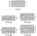
- FIG. 1 is a schematic structural view of the battery in the first approach.
- the battery according to the first approach includes a positive electrode 3, a first aqueous electrolyte AE1 held by the positive electrode 3, a negative electrode 4, a second aqueous electrolyte AE2 held by the negative electrode 4, at least one separator 5 interposed between the positive electrode 3 and the negative electrode 4, and a third aqueous electrolyte AE3 held by the separator 5, in which at least one of the type of salt, the concentration of salt, the pH, and the osmotic pressure of the third aqueous electrolyte AE3 is different from both those of the first aqueous electrolyte AE1 and those of the second aqueous electrolyte AE2.
- the battery according to the present approach can be also used as a secondary battery.
- the battery according to the present approach when used as a secondary battery will be described in detail below.
- electrolysis of water may occur as a side reaction of the aqueous electrolyte.
- a reaction represented by formula (1) occurs at a negative electrode
- a reaction represented by formula (2) occurs at a positive electrode.
- thermodynamic potential window in which an aqueous electrolyte stays stable does not depend on pH and constant (1.23 V).
- aqueous electrolytes are used for a positive electrode and a negative electrode, in which an aqueous electrolyte that is resistant to oxidation, that is, an acidic aqueous electrolyte is used for the positive electrode and an aqueous electrolyte that is resistant to reduction, that is, an basic aqueous electrolyte is used for the negative electrode, it is possible to achieve a thermodynamic potential window of the whole aqueous electrolyte of the battery of 1.23 V or more.
- the positive electrode side aqueous electrolyte and the negative electrode side aqueous electrolyte are different in pH from each other.
- an aqueous electrolyte having a high electrolyte salt concentration is sometimes used for a positive electrode, and an aqueous electrolyte having a low electrolyte salt concentration is sometimes used for a negative electrode.
- each of the reaction potentials at the positive electrode and the negative electrode are defined by each of the electrolyte salt concentrations in the aqueous electrolytes. Specifically, when the electrolyte salt concentration is high, a reaction proceeds under a high reaction potential, and when the electrolyte salt concentration is low, a reaction proceeds under a low reaction potential.
- a third aqueous electrolyte in which at least one of the type of salt, the concentration of salt, the pH, and the osmotic pressure is different from both those of the first aqueous electrolyte and those of the second aqueous electrolyte is used.
- any of the type of salt, the concentration of salt, the pH, and the osmotic pressure of the third aqueous electrolyte is necessarily different from those of the first aqueous electrolyte
- any of the type of salt, the concentration of salt, the pH, and the osmotic pressure of the third aqueous electrolyte is necessarily different from those of the second aqueous electrolyte.
- the types of salt, the concentrations of salt, the pH, and the osmotic pressures are different between the first aqueous electrolyte and the second aqueous electrolyte
- the types of salt, the concentrations of salt, the pH, and the osmotic pressures tend to approach an equilibrium state between the first aqueous electrolyte and the second aqueous electrolyte, that is, tend to become equal or close to each other.
- the concentrations of salt, and pH concentration of H +
- the third aqueous electrolyte plays a role in preventing mixing of the first aqueous electrolyte and the second aqueous electrolyte.
- the third aqueous electrolyte is mixed with each of the first aqueous electrolyte and the second aqueous electrolyte.
- the following state can be virtually made: osmotic pressure of the first aqueous electrolyte ⁇ osmotic pressure of the third aqueous electrolyte ⁇ osmotic pressure of the second aqueous electrolyte.
- the osmotic pressure of the third aqueous electrolyte when the osmotic pressure of the third aqueous electrolyte is close to those of the first and the second aqueous electrolytes, transfer of water molecules due to the osmotic pressure difference can be prevented.
- the transfer of water molecules becomes more difficult as the osmotic pressure difference is smaller.
- the mobility of water molecules from the second aqueous electrolyte to the third aqueous electrolyte is lower than the mobility of the water molecules from the second aqueous electrolyte to the first aqueous electrolyte.
- the mobility of water molecules from the first aqueous electrolyte to the third aqueous electrolyte is lower than the mobility of water molecule from the first aqueous electrolyte to the second aqueous electrolyte.
- the separator is impregnated with the third aqueous electrolyte, the third aqueous electrolyte exist in the separator more steadily than an electrolyte that permeates the separator by capillary phenomenon generally when a battery is assembled.
- mixing of the first aqueous electrolyte and the second aqueous electrolyte included in the battery according to the present approach is difficult to proceed.
- the time dependent mixing of the first aqueous electrolyte and the second aqueous electrolyte decreases in cycle deterioration and coulombic efficiency can be prevented. Since the coulombic efficiency represents the slope of a self-discharge curve, this shows that when the coulombic efficiency decreases, storage performance also decreases.
- the battery according to the present approach is manufactured as follows. On an electric insulating plate (e.g., plastics), a positive electrode having an uncoated portion for current collection is fixed, a first electrolyte is dropped, and then a separator that has been impregnated with a third electrolyte in advance is disposed thereon and brought into close contact therewith. On the separator, a second electrolyte is dropped, a negative electrode is placed thereon and brought into close contact therewith, and a plastic plate is placed thereon and fixed with a screw.
- an electric insulating plate e.g., plastics
- a positive electrode, a first aqueous electrolyte, a separator impregnated with a third electrolyte, a second aqueous electrolyte, a negative electrode, a separator impregnated with a third electrolyte, a positive electrode, and a first aqueous electrolyte,... are repeatedly stacked to form the repeated stacked structure, and a plastic plate is placed at the end and fixed with a screw.
- the third aqueous electrolyte at least one of the type of salt, the concentration of salt, the pH, and the osmotic pressure is different from both those of the positive electrode side aqueous electrolyte and those of the negative electrode side aqueous electrolyte.
- an electrolyte (the third aqueous electrolyte) having an osmotic pressure that is close to the osmotic pressure of each of the electrolytes of an electrolyte on the positive electrode side (the first aqueous electrolyte) and an electrolyte on the negative electrode side (the second aqueous electrolyte) can be achieved.
- the impregnation of the separator with the third electrolyte is, for example, performed under the following conditions: at 25°C, evacuation until about 10 -1 Pa, and standing for 24 hours or more.
- the negative electrode includes a negative electrode current collector, and a negative electrode active material layer disposed on the negative electrode current collector.
- the negative electrode active material layer is disposed on at least one surface of the negative electrode current collector.
- the negative electrode active material layer may be disposed on one of the surfaces of the negative electrode current collector, or the negative electrode active material layers may be arranged on one of the surfaces of the negative electrode current collector and the back surface thereof.
- the negative electrode active material layer includes a negative electrode active material containing at least one compound selected from the group consisting of a titanium oxide, a lithium titanium oxide, and a lithium titanium composite oxide. These oxides may be used alone or in combination of two or more. In these oxides, Li insertion and extraction reaction occurs within a range of 1 V or more and 2 V or less (vs. Li/Li + ) relative to a lithium reference potential. For this reason, when these oxides described above are used as the negative electrode active material of the secondary battery, the change in volume due to expansion and contraction, which accompany charge and discharge, is small, and thus the life of the secondary battery is extended.
- At least one element selected from the group consisting of Zn, Ga, In, Bi, Tl, Sn, Pb, Ti, and Al is contained in the negative electrode current collector.
- these elements may be also referred to as elements A. These elements may be used alone, or a plurality of the elements may be used in combination. These elements may be contained as metals or as an alloy of the metals. The metals and alloy of the metals may be contained alone or as a mixture of two or more.
- the elements are contained in the current collector, the mechanical strength of the current collector is increased, and thus the workability is improved. Further, electrolysis of an aqueous solvent is prevented, and the effect of preventing hydrogen generation can be increased.
- Zn, Pb, Ti, and Al are more preferred.
- the current collector is, for example, a metal foil made from these metals.
- the current collector is, for example, a foil made from an alloy containing these metals.
- the foil may contain, for example, one of elements described below or two or more of the elements, in addition to the element A.
- Examples of the form of the metal body include a mesh and a porous body, besides the foil.
- the foil which has a small volume and a large surface are, is desired.
- the negative electrode current collector may include a substrate containing a metal that is different from the element A.
- the hydrogen generation can be prevented.
- the compound containing the element A that is present on the surface is preferably arranged so as to be in contact with the negative electrode active material layer.
- plating of the element A can be applied to the substrate, and thereby the compound containing the element A can be provided on the surface of the substrate.
- plating treatment using an alloy containing the element A can be applied to the surface of the substrate.
- the current collector may include at least one compound selected from the elements A.
- An oxide of the element A, and/or a hydroxide of the element A, and/or a basic carbonate compound of the element A, and/or a sulfate compound of the element A are preferably included in at least a part of the surface region of the current collector within a depth region of 5 nm or more and 1 ⁇ m or less in the depth direction from the surface.
- the oxide of element A include ZnO
- examples of the hydroxide of element A include Zn(OH) 2
- examples of the basic carbonate compound of element A include 2ZnCO 3 ⁇ 3Zn(OH) 2
- examples of the sulfate compound of element A include ZnSO 4 ⁇ 7H 2 O.
- the oxide of the element A, the hydroxide of the element A, the basic carbonate compound of the element A, and the sulfate compound of the element A is present in the surface layer portion of the current collector, hydrogen generation can be prevented.
- these compounds are present in the surface layer portion of the current collector, the adhesion among the current collector, the active material, a conductive agent, and a binder is improved, and electronic conduction paths can be increased. Thus, it is possible to improve the cycle performance and reduce the electrical resistance.
- the substrate preferably contains at least one metal selected from the group consisting of Al, Fe, Cu, Ni, and Ti. These metals may be contained as an alloy.
- the substrate may contain the metal and metal alloy alone or as a mixture of two or more. From the standpoint of weight reduction, the substrate preferably contains Al, Ti, or an alloy thereof.
- the current collector includes at least one compound selected from the elements A can be examined by disassembling the battery as described above, and then performing inductively coupled plasma (ICP) emission spectrometry.
- ICP inductively coupled plasma
- the negative electrode active material includes one compound or two or more compounds selected from the group consisting of a titanium oxide, a lithium titanium oxide, and a lithium titanium composite oxide.
- the lithium titanium composite oxide include a niobium titanium oxide and a sodium niobium titanium oxide.
- the compounds desirably have a Li insertion potential within a range of 1 V (vs. Li/Li + ) or more and 3 V (vs. Li/Li + ) or less.
- the titanium oxide includes, for example, a titanium oxide having a monoclinic structure, a titanium oxide having a rutile structure, and a titanium oxide having an anatase structure.
- the composition before charge can be expressed as TiO 2
- the composition after charge can be expressed as Li x TiO 2 (0 ⁇ x).
- the structure of titanium oxide having a monoclinic structure before charge can be expressed as TiO 2 (B).
- lithium titanium oxide examples include a lithium titanium oxide having a spinel structure (e.g., Li 4+x Ti 5 O 12 (-1 ⁇ x ⁇ 3) ; and a lithium titanium oxide having a ramsdellite structure (e.g., Li 2+x Ti 3 O 7 (-1 ⁇ x ⁇ 3), Li 1+x Ti 2 O 4 (0 ⁇ x ⁇ 1), Li 1.1+x Ti 1.8 O 4 (0 ⁇ x ⁇ 1), Li 1.07+x Ti 1.86 O 4 (0 ⁇ x ⁇ 1), and Li x TiO 2 (0 ⁇ x ⁇ 1).
- a lithium titanium oxide having a spinel structure e.g., Li 4+x Ti 5 O 12 (-1 ⁇ x ⁇ 3)
- a lithium titanium oxide having a ramsdellite structure e.g., Li 2+x Ti 3 O 7 (-1 ⁇ x ⁇ 3)
- Li 1+x Ti 2 O 4 (0 ⁇ x ⁇ 1)
- niobium titanium oxide examples include a niobium titanium oxide represented by Li a TiM b Nb 2 ⁇ O 7 ⁇ (0 ⁇ a ⁇ 5, 0 ⁇ b ⁇ 0.3, 0 ⁇ ⁇ ⁇ 0.3, 0 ⁇ ⁇ ⁇ 0.3, where M is at least one kind of elements selected from the group consisting of Fe, V, Mo, and Ta).
- Examples of the sodium niobium titanium oxide include an orthorhombic Na-containing niobium titanium composite oxide represented by Li 2+v Na 2-w M1 x Ti 6-y-z Nb y M2 z O 14+ ⁇ (0 ⁇ v ⁇ 4, 0 ⁇ w ⁇ 2, 0 ⁇ x ⁇ 2, 0 ⁇ y ⁇ 6, 0 ⁇ z ⁇ 3, -0.5 ⁇ ⁇ ⁇ 0.5, M1 includes at least one selected from Cs, K, Sr, Ba, and Ca, and M2 includes at least one selected from Zr, Sn, V, Ta, Mo, W, Fe, Co, Mn, and Al.
- M1 includes at least one selected from Cs, K, Sr, Ba, and Ca
- M2 includes at least one selected from Zr, Sn, V, Ta, Mo, W, Fe, Co, Mn, and Al.
- Examples of the compound preferred as the negative electrode active material include a titanium oxide having an anatase structure, a titanium oxide having a monoclinic structure, and a lithium titanium oxide having a spinel structure. These compounds have a Li insertion potential of from 1.4 V (vs. Li/Li + ) to 2 V (vs. Li/Li + ) . Thus, each of them is used in combination with, for example, a lithium manganese oxide as the positive electrode active material so that a high electromotive force can be obtained.
- the lithium titanium oxide having a spinel structure is preferred because it exhibits little volume change in the charge-discharge reaction.
- the negative electrode active material layer contains a negative electrode active material, for example, in the form of particles.
- Negative electrode active material particles may be single primary particles, secondary particles which are aggregates of the primary particles, or a mixture of single primary particles and secondary particles.
- the shape of the particles is not particularly limited, and may be, for example, a spherical shape, an elliptical shape, a flat shape or a fibrous shape.
- the average particle size (diameter) of the secondary particle of the negative electrode active material is preferably 3 ⁇ m or more. More preferably, the average particle size is 5 ⁇ m or more and 20 ⁇ m or less. When the average particle size is within this range, the surface area of the active material is large, and thus the effect of preventing hydrogen generation can be increased.
- the negative electrode active material having secondary particles with an average particle size of 3 ⁇ m or more is produced by, for example, the following method. First, an active material precursor having an average particle size of 1 ⁇ m or less is produced by the synthesis of raw materials of the active material. Thereafter, the active material precursor is sintered and the resulting product is ground using a grinder such as a ball mill or jet mill. After that, the active material precursor is aggregated in the sintering process so that the secondary particles are grown to have a large particle size.
- the average particle size of the primary particles of the negative electrode active material is desirably 1 ⁇ m or less. This reduces the diffusion length of Li ions in the active material and increases the specific surface area. Therefore, high input performance (rapid charging performance) can be achieved. On the other hand, when the average particle size is small, the particles can be easily aggregated. As a result, a larger amount of the electrolyte may be distributed to the negative electrode, and consequently the electrolyte may be exhausted at the positive electrode. Thus, the lower limit of the average particle size is desirably 0.001 ⁇ m.
- the average particle size is more preferably 0.1 ⁇ m or more and 0.8 ⁇ m or less.
- the negative electrode active material particles preferably have a specific surface area of 3 m 2 /g or more and 200 m 2 /g or less as determined by a BET method employing N 2 deposition. This can further increase the affinity between the negative electrode and the electrolyte.
- the negative electrode active material layer (excluding the current collector) desirably has a specific surface area of 3 m 2 /g or more and 50 m 2 /g or less.
- the specific surface area is more preferably 5 m 2 /g or more and 50 m 2 /g or less.
- the negative electrode active material layer may be a porous layer including the negative electrode active material, the conductive agent, and the binder, and may be supported on the current collector.
- the porosity of the negative electrode (excluding the current collector) is preferably within a range of from 20% to 50%. Accordingly, it is possible to produce a negative electrode having an excellent affinity of the negative electrode for the electrolyte solution and a high density. More preferably, the porosity is within a range of from 25% to 40%.
- the conductive agent examples include carbon materials such as acetylene black, carbon black, coke, carbon fiber, and graphite, and powders of a metal such as nickel or zinc.
- the conductive agent may be used alone or in combination of two or more. Since the carbon material generates hydrogen in itself, it is desirable to use the metal powder as the conductive agent.
- binder examples include polytetrafluoroethylene (PTFE), polyvinylidene fluoride (PVdF), fluorine based rubber, ethylene butadiene rubber, polypropylene (PP), polyethylene (PE), carboxymethylcellulose (CMC), polyimide (PI), and polyacrylimide (PAI).
- PTFE polytetrafluoroethylene
- PVdF polyvinylidene fluoride
- PP polypropylene
- PE polyethylene
- CMC carboxymethylcellulose
- PI polyimide
- PAI polyacrylimide
- the binder may be used alone or in combination of two or more.
- the mixing ratio of the negative electrode active material is preferably in a range of 70 wt% or more and 95 wt% or less
- the mixing ratio of the conductive agent is preferably in a range of 3 wt% or more and 20 wt% or less
- the mixing ratio of the binder is preferably in a range of 2 wt% or more and 10 wt% or less.
- the mixing ratio of the conductive agent is 3 wt% or more, the conductivity of the negative electrode can be improved.
- the mixing ratio is 20 wt% or less, decomposition of the electrolyte on the surface of the conductive agent can be reduced.
- the mixing ratio of the binder is 2 wt% or more, sufficient electrode strength can be obtained.
- the mixing ratio is 10 wt% or less, an insulating portion of the electrode can be decreased.
- the negative electrode can be produced, for example, as follows. First, the negative electrode active material, the conductive agent, and the binder are dispersed in an appropriate solvent to prepare a slurry. Next, the slurry is applied to the current collector, and the coating film is dried to form the negative electrode active material layer on the current collector.
- the slurry may be applied to one surface of the current collector, or may be applied to one of the surfaces of the current collector and the back surface thereof. Then, the current collector and the negative electrode active material layer may be subjected to pressing such as heat pressing to produce the negative electrode.
- the positive electrode may include a positive electrode current collector, and a positive electrode layer that include an active material, a conductive agent, and a binder and may be supported on one of the surfaces or both of the surfaces of the positive electrode current collector.
- the positive electrode current collector it is preferred to use a foil, a porous body, or a mesh made from a metal such as stainless steel, Al, or Ti.
- the surface of the current collector may be coated with dopant.
- a positive electrode active material allowing lithium or sodium to be inserted thereinto and extracted therefrom may be used.
- the positive electrode may contain one kind or two or more kinds of positive electrode active materials.
- the positive electrode active material include a lithium manganese composite oxide, a lithium nickel composite oxide, a lithium cobalt aluminum composite oxide, a lithium nickel cobalt manganese composite oxide, a spinel type lithium manganese nickel composite oxide, a lithium manganese cobalt composite oxide, a lithium iron oxide, a fluorinated lithium iron sulfate, and a phosphate compound having an olivine crystal structure (e.g., Li x FePO 4 (0 ⁇ x ⁇ 1), Li x MnPO 4 (0 ⁇ x ⁇ 1)).
- the phosphate compound having an olivine crystal structure is excellent in thermal stability.
- Examples of the positive electrode active material by which a high positive electrode potential is obtained will be described below.
- Examples thereof include Li x Mn 2 O 4 (0 ⁇ x ⁇ 1) having a spinel structure, a lithium manganese composite oxide (e.g., Li x MnO 2 (0 ⁇ x ⁇ 1)), a lithium nickel aluminum composite oxide (e.g., Li x Ni 1-y Al y O 2 (0 ⁇ x ⁇ 1,0 ⁇ y ⁇ 1)), a lithium cobalt composite oxide (e.g., Li x CoO 2 (0 ⁇ x ⁇ 1), a lithium nickel cobalt composite oxide (e.g., Li x Ni 1-y-z CO y Mn z O 2 (0 ⁇ x ⁇ 1,0 ⁇ y ⁇ 1, 0 ⁇ z ⁇ 1), a lithium manganese cobalt composite oxide (e.g., Li x Mn y Co 1-y O 2 (0 ⁇ x ⁇ 1, 0 ⁇ y ⁇ 1)
- Examples include a sodium manganese composite oxide, a sodium nickel composite oxide, a sodium cobalt composite oxide, a sodium nickel cobalt manganese composite oxide, a sodium iron composite oxide, sodium phosphorus oxide (e.g., sodium iron phosphate, sodium vanadium phosphate), a sodium iron manganese composite oxide, a sodium nickel titanium composite oxide, a sodium nickel iron composite oxide, and a sodium nickel manganese composite oxide.
- a sodium manganese composite oxide e.g., sodium nickel composite oxide, a sodium cobalt composite oxide, a sodium nickel cobalt manganese composite oxide, a sodium iron composite oxide, sodium phosphorus oxide (e.g., sodium iron phosphate, sodium vanadium phosphate), a sodium iron manganese composite oxide, a sodium nickel titanium composite oxide, a sodium nickel iron composite oxide, and a sodium nickel manganese composite oxide.
- the positive electrode active material include an iron composite oxide (e.g., Na y FeO 2 , 0 ⁇ y ⁇ 1), an iron manganese composite oxide (e.g., Na y Fe 1-x Mn x O 2 , 0 ⁇ x ⁇ 1, 0 ⁇ y ⁇ 1), a nickel titanium composite oxide (e.g., Na y Ni 1-x Ti x O 2 , 0 ⁇ x ⁇ 1, 0 ⁇ y ⁇ 1), a nickel iron composite oxide (e.g., Na y Ni 1-x Fe x O 2 , 0 ⁇ x ⁇ 1,0 ⁇ y ⁇ 1), a nickel manganese composite oxide (e.g., Na y Ni 1-x Mn x O 2 , 0 ⁇ x ⁇ 1, 0 ⁇ y ⁇ 1), a nickel manganese iron composite oxide (e.g., Na y Ni 1-x-z Mn x Fe z O 2 , 0 ⁇ y
- the positive electrode active material particles may be single primary particles, secondary particles which are aggregates of the primary particles, or may include single primary particles and secondary particles.
- the primary particles of the positive electrode active material preferably have an average particle size (diameter) of 10 ⁇ m or less, more preferably of 0.1 ⁇ m to 5 ⁇ m.
- the secondary particles of the positive electrode active material preferably have an average particle size (diameter) of 100 ⁇ m or less, more preferably of 10 ⁇ m to 50 ⁇ m.
- the particle of the positive electrode active material is coated with a carbon material.
- the carbon material may be in the form of a layered structure, a particulate structure, or a form of aggregated particles.
- examples include acetylene black, carbon black, graphite, and carbon fiber having an average fiber diameter of 1 ⁇ m or less.
- the conductive agent may be used alone or in combination of two or more.
- binder for binding the active material and the conductive agent examples include polytetrafluoroethylene (PTFE), polyvinylidene fluoride (PVdF), fluorine based rubber, stylene butadiene rubber (SBR), polypropylene (PP), polyethylene (PE), carboxymethylcellulose (CMC), polyimide (PI), and polyacrylimide (PAI).
- PTFE polytetrafluoroethylene
- PVdF polyvinylidene fluoride
- SBR stylene butadiene rubber
- PP polypropylene
- PE polyethylene
- CMC carboxymethylcellulose
- PI polyimide
- PAI polyacrylimide
- the binder may be used alone or in combination of two or more.
- the mixing ratio of the positive electrode active material is preferably in a range of 70 wt% or more and 95 wt% or less
- the mixing ratio of the conductive agent is in a range of preferably 3 wt% or more and 20 wt% or less
- the mixing ratio of the binder is preferably in a range of 2 wt% or more and 10 wt% or less.
- the mixing ratio of the conductive agent is 3 wt% or more, the conductivity of the positive electrode can be improved.
- the mixing ratio is 20 wt% or less, decomposition of the electrolyte on the surface of the conductive agent can be reduced.
- the mixing ratio of the binder is 2 wt% or more, sufficient electrode strength can be obtained.
- the mixing ratio is 10 wt% or less, an insulating portion of the electrode can be decreased.
- the positive electrode can be produced, for example, as follows. First, the positive electrode active material, the conductive agent, and the binder are dispersed in an appropriate solvent to prepare a slurry. Next, the slurry is applied to the current collector, and the coating film is dried to form the positive electrode layer on the current collector.
- the slurry may be applied to one surface of the current collector, or may be applied to one of the surfaces of the current collector and the back surface thereof. Then, the current collector and the positive electrode layer may be subjected to pressing such as heat pressing to produce the positive electrode.
- a separator may be disposed between the positive electrode and the negative electrode. It is sufficient that at least one separator is present between the positive electrode and the negative electrode. Thus, a plurality of the separators may be directly stacked on each other and the stacked layers may be provided between the positive electrode and the negative electrode, or the separator and another member may be laminated and the laminate may be provided between the positive electrode and the negative electrode.
- the separator is constituted of an insulating material, electrical contact between the positive electrode and the negative electrode can be prevented.
- the separator include non-woven fabrics, films, and paper. Examples of a constitution material of the separator include polyolefins such as polyethylene and polypropylene; and cellulose. Preferable examples of the separator include cellulose fiber-containing non-woven fabrics and polyolefin fiber-containing porous films.
- the separator preferably has a porosity of 60% or more.
- the fiber diameter is preferably 10 ⁇ m or less. When the fiber diameter is 10 ⁇ m or less, the affinity of the separator with an electrolyte is enhanced, so that battery resistance can be reduced.
- the fiber diameter is more preferably 3 ⁇ m or less.
- a cellulose fiber containing nonwoven fabric having a porosity of 60% or more can be well impregnated with the electrolyte, and can exhibit a high output performance at from a low temperature to a high temperature.
- the separator does not react with the negative electrode, and a short-circuit between the negative electrode and the positive electrode due to precipitation of dendrite of lithium metal does not occur.
- the porosity is more preferably in a range of 62% to 80%.
- the separator preferably has a thickness in a range of 20 ⁇ m or more and 100 ⁇ m or less, and a density in a range of 0.2 g/cm 3 or more and 0.9 g/cm 3 or less. Within these ranges, the mechanical strength and the reduction of battery resistance can be well-balanced, and a secondary battery having a high output and having a suppressed internal short-circuit can be provided. In addition, there is a reduced thermal contraction of the separator under a high temperature environment, and storage performance under a high temperature becomes good.
- the separator preferably has an air permeability coefficient of 1 ⁇ 10 -14 m 2 or less.
- the air permeability coefficient is more preferably 1 ⁇ 10 -15 m 2 or less, and still more preferably 1 ⁇ 10 -16 m 2 or less.
- the separator having such an air permeability coefficient can kinetically sufficiently prevent the mixing of the positive electrode side aqueous electrolyte and the negative electrode side aqueous electrolyte, and thus the coulombic efficiency is improved, which is favorable. This is because the separator is sufficiently impregnated with the aqueous electrolyte to reduce the resistance of the separator and increase the ion conductivity, and thus the rate performance is improved. Although the separator is well impregnated with the aqueous electrolytes, the aqueous electrolytes on the positive electrode side and the negative electrode side may not be mixed with each other.
- the air permeability coefficient (m 2 ) is calculated as follows.
- a gas having a viscosity coefficient ⁇ (Pa ⁇ s) is transmitted through the separator within a measurement area A (m 2 ).
- the gas is transmitted through the separator under a plurality of conditions in which pressures p (Pa) of the gas to be supplied are different from each other, and quantities Q (m 3 /s) of the gas transmitted through the separator under the plurality of conditions are measured.
- An example of methods for calculating the air permeability coefficient KT is as follows. A separator is sandwiched between a pair of stainless steel plates each having a hole having a diameter of 10 mm. From the hole of the one stainless steel plate, air is supplied with a pressure p. Then, gas quantity Q of the air escaped from the hole of the other stainless steel plate is measured. Thus, the area of the hole (25n mm 2 ) is applied as the measurement area A, and 0.000018 Pa ⁇ s is applied as the viscosity coefficient ⁇ . The gas quantity Q is calculated by measuring the amount of air ⁇ (m 3 ) escaped from the hole within 100 seconds, and dividing the amount ⁇ measured above by 100.
- gas quantities Q at the pressures p are measured as described above. For example, under 4 conditions with pressures p of 1000 Pa, 2500 Pa, 4000 Pa, and 6000 Pa, gas quantities Q at the pressures p are measured. Then, plots of the gas quantities Q measured under the 4 conditions versus the pressures p are made, and dQ/dp, which means the slope of the plotted curve of the gas quantities Q versus the pressures p, is obtained by linear fitting (least-squares method). The slope (dQ/dp) obtained above is multiplied by ( ⁇ L)/A to calculate the air permeability coefficient KT.
- the measurement of the air permeability coefficient of a separator of a battery is performed as follows.
- the battery is disassembled and the separator is separated from other components of the battery.
- Both of the surfaces of the separator are washed with pure water, then the separator is immersed in pure water and left to stand for 48 hours or more. Thereafter, the both surfaces are further washed with pure water, dried in a vacuum drying oven at 100°C for 48 hours or more, and then the air permeability coefficient is measured.
- the air permeability coefficients at a plurality of random portions of the separator are measured.
- the lowest air permeability coefficient value among the air permeability coefficient values obtained at the plurality of random portions is designated as an air permeability coefficient of the separator.
- inorganic solid particles can also be used.
- the inorganic solid particles can be used as the separator in the form of a solid electrolyte membrane including the inorganic solid particles and a polymer material.
- a composite solid electrolyte membrane in which the solid electrolyte membrane is applied to at least one main surface of a porous self-supported film such as the above-described nonwoven fabric or paper can also be used.
- Each of the solid electrolyte membrane and the porous self-supported film can contain the third aqueous electrolyte.
- the separator may be a porous self-supported film or a solid electrolyte membrane, or may be a composite solid electrolyte membrane including a solid electrolyte membrane on at least one main surface of a porous self-supported film.
- the separator may be a laminated body formed of two or more selected from a porous self-supported film, a solid electrolyte membrane, and a composite solid electrolyte membrane.
- the third aqueous electrolyte can be contained in the overall composite solid electrolyte membrane.
- the solid electrolyte membrane can contain inorganic solid particles and a polymer material.
- the solid electrolyte membrane may further contain a plasticizer and/or an electrolyte salt.
- porous self-supported film examples include nonwoven fabric, a porous film including organic fibers, paper, etc.
- FIG. 2 is a schematic structural view of the separator in the battery according to the first approach.
- FIG. 2A represents a case in which only the solid electrolyte membrane is used as the separator.
- FIG. 2B represents a case in which a composite solid electrolyte membrane A having the solid electrolyte membrane formed on one of the main surfaces of the porous self-supported film is used as the separator, and
- FIG. 2A represents a case in which only the solid electrolyte membrane is used as the separator.
- FIG. 2B represents a case in which a composite solid electrolyte membrane A having the solid electrolyte membrane formed on one of the main surfaces of the porous self-supported film is used as the separator, and
- FIG. 2C represents a case in which a composite solid electrolyte membrane B having solid electrolyte membranes formed on both of the main surfaces of the porous membrane is used as the separator
- FIG. 2D represents a case in which a laminate in which a plurality of composite solid electrolyte membranes A are laminated is used as the separator.
- the separator include, in addition to those described above, a separator in which the composite solid electrolyte membrane A and the composite solid electrolyte membrane B are laminated, a separator in which the composite electrolyte membranes B are laminated, and a separator in which the solid electrolyte membrane, the composite solid electrolyte membrane A, and/or the composite solid electrolyte membrane B are laminated.
- the solid electrolyte membrane, the composite solid electrolyte membrane A, and the composite solid electrolyte membrane B may be used in an appropriate combination.
- the solid electrolyte membrane is preferably present on the negative electrode side or on the second aqueous electrolyte side.
- the diffusion length that contributes to mixing of the positive electrode electrolyte and the negative electrode electrolyte is increased and, furthermore, the possibility of occurring a micro-short-circuit is reduced such that cycle performance and storage performance are improved. It is particularly preferred that a separator in which, as shown in FIG. 2D , the solid electrolyte is applied to both of the main surfaces of the porous self-supported film to form solid electrolyte membranes on both surfaces of the porous self-supported film is used.
- the middle substrate (porous membrane) portion can be sufficiently impregnated with the third aqueous electrolyte, and contact of each of the positive electrode and the negative electrode with the electrolyte can be minimized. Thus, a high cycle performance can be achieved.
- the inorganic solid particles include oxide ceramics such as alumina, silica, zirconia, yttria, magnesium oxide, calcium oxide, barium oxide, strontium oxide, and vanadium oxide; carbonates and sulfates such as sodium carbonate, potassium carbonate, magnesium carbonate, calcium carbonate, barium carbonate, lanthanum carbonate, cerium carbonate, calcium sulfate, magnesium sulfate, aluminum sulfate, gypsum, and barium sulfate; phosphates such as hydroxylapatite, lithium phosphate, zirconium phosphate, and titanium phosphate; and nitride ceramics such as silicon nitride, titanium nitride, and boron nitride.
- oxide ceramics such as alumina, silica, zirconia, yttria, magnesium oxide, calcium oxide, barium oxide, strontium oxide, and vanadium oxide
- carbonates and sulfates such
- the inorganic solid particles preferably have alkali metal-ion ion conductivity.
- examples of the inorganic solid particles having lithium ion conductivity include an oxide-based solid electrolyte or a sulfide-based solid electrolyte.
- oxide-based solid electrolyte a lithium phosphate solid electrolyte having a sodium (Na) super ionic conductor (NASICON) structure and represented by a general formula LiM2(PO4)3 is preferably used.
- M in the above-described general formula is, for example, at least one element selected from the group consisting of titanium (Ti), germanium (Ge), strontium (Sr), zirconium (Zr), tin (Sn), aluminum (Al), and calcium (Ca).
- the ionic conductivity of the lithium phosphate solid electrolyte represented by the general formula LiM 2 (PO 4 ) 3 is, for example, 1 ⁇ 10 -7 S/cm or more and 1 ⁇ 10 -3 S/cm or less.
- lithium phosphate solid electrolyte having the NASICON structure examples include LATP (Li 1+x+y Al x (at least one of Ti and Ge) 2-x Si y P 3-y O 12 , in which 0 ⁇ x ⁇ 2, and 0 ⁇ y ⁇ 3) ; Li 1+x Al x Ge 2-x (PO 4 ) 3 , in which 0 ⁇ x ⁇ 2; Li 1+x Al x Zr 2-x (PO 4 ) 3 , in which 0 ⁇ x ⁇ 2; and Li 1+2x Zr 1-x Ca x (PO 4 ) 3 , in which 0 ⁇ x ⁇ 1.
- the electrolyte represented by Li 1+2x Zr 1-x Ca x (PO 4 ) 3 is highly water resistant, low in reduction property, and low in cost, and thus preferably used as the inorganic solid electrolyte particle.
- oxide-based solid electrolyte examples include, in addition to the above-described lithium phosphate solid electrolytes, LIPON (Li 2.9 PO 3.3 N 0.46 ) in an amorphous state, La 5+x A x La 3-x M 2 O 12 (A is at least one selected from the group consisting of Ca, Sr, and Ba, and M is at least one of Nb and Ta) having a garnet structure, and Li 3 M 2-x L 2 O 12 (M is at least one of Ta and Nb, and L is Zr), Li 7-3x Al x La 3 Zr 3 O 12 , and LLZ (Li 7 La 3 Zr 2 O 12 ).
- the solid electrolyte may be used alone or in combination of two or more.
- the ionic conductivity of LIPON is, for example, 1 ⁇ 10 -7 S/cm or more and 5 ⁇ 10 -6 S/cm or less.
- the ionic conductivity of LLZ is, for example, 1 ⁇ 10 -7 S/cm or more and 5 ⁇ 10 -4 S/cm or less.
- a sodium-containing solid electrolyte may be used as the inorganic solid particles having sodium-ion ion conductivity.
- the sodium-containing solid electrolyte is superior in the sodium-ion ion conductivity.
- Examples of the sodium-containing solid electrolyte include ⁇ -alumina, sodium phosphorus sulfide, and sodium phosphorus oxide.
- the sodium ion-containing solid electrolyte is preferably in a glass-ceramic form.
- the inorganic solid particles preferably are a solid electrolyte having a lithium ion conductivity of 1 ⁇ 10 -7 S/cm or more at 25°C.
- the lithium ion conductivity can be measured by, for example, an alternate current impedance method.
- the lithium ion conductivity can be measured specifically as follows. First, the inorganic solid particles are shaped using a tableting machine to obtain a compressed powder pellet. Both of the surfaces of the compressed powder pellet are coated with evaporated gold (Au) to obtain a measurement sample.
- the alternate current impedance of the measurement sample is measured using impedance measuring equipment. As a measuring equipment, for example, a frequency response analyzer model 1260 manufactured by Solartron can be used. The measurement is performed at a measuring frequency of 5 Hz to 32 MHz and a measuring temperature of 25°C under argon atmosphere.
- ⁇ Li 1 / Z Li ⁇ d / S
- the shape of the inorganic solid particle is not particularly limited and can be, for example, spherical, elliptical, flat, or fibrous.
- the average particle size of the inorganic solid particles is preferably 15 ⁇ m or less, and more preferably 12 ⁇ m or less. When the average particle size of the inorganic solid particles is small, the fineness of the solid electrolyte membrane can be increased.
- the average particle size of the inorganic solid particles is preferably 0.01 ⁇ m or more, and more preferably 0.1 ⁇ m or more. When the average particle size of the inorganic solid particles is large, aggregation of the particles tends to be inhibited.
- the average particle size of the inorganic solid particles means a particle size with which a volume integrated value becomes 50% in a particle size distribution obtained by a laser diffraction particle size distribution measurement apparatus.
- a dispersion obtained by diluting the inorganic solid particles by ethanol such that the concentration of the inorganic solid particles becomes 0.01 mass% to 5 mass% is used.
- One type of the inorganic solid particle may be used alone, or two or more type of the inorganic solid particles may be used as a mixture.
- the inorganic solid particles preferably are a main component.
- the ratio of the inorganic solid particles in the solid electrolyte membrane is, from the standpoint of improving the ion conductivity of the solid electrolyte membrane, preferably 70 mass% or more, more preferably 80 mass% or more, and still more preferably 85 mass% or more.
- the ratio of the inorganic solid particles in the solid electrolyte membrane is, from the standpoint of improving the membrane strength of the solid electrolyte membrane, preferably 98 mass% or less, more preferably 95 mass% or less, and still more preferably 90 mass% or less.
- the ratio of the inorganic solid particles in the solid electrolyte membrane can be calculated by thermogravimetric (TG) analysis.
- the polymer material included in the solid electrolyte membrane improves the binding property between the inorganic solid particles.
- the weight-average molecular weight of the polymer material is, for example, 3000 or more. When the weight-average molecular weight of the polymer material is 3,000 or more, the binding property of the inorganic solid particles can be further improved.
- the weight-average molecular weight of the polymer material is preferably 3,000 or more and 5,000,000 or less, more preferably 5,000 or more and 2,000,000 or less, and still more preferably 10,000 or more and 1,000,000 or less.
- the weight-average molecular weight of the polymer material can be obtained by gel permeation chromatography (GPC).
- the polymer material can be a polymer containing one type of monomer unit, a copolymer containing a plurality of monomer units, or a mixture thereof.
- the polymer material preferably contains a monomer unit that includes a hydrocarbon having a functional group containing one element or two or more elements selected from the group consisting of oxygen (O), sulfur (S), nitrogen (N), and fluorine (F).
- a portion that is constituted by the monomer unit preferably accounts for 70 mol% or more of the polymer material.
- this monomer unit is referred to as a first monomer unit.
- a monomer unit other than the first monomer unit is referred to as a second monomer unit.
- a copolymer of the first monomer unit and the second monomer unit may be an alternating copolymer, a random copolymer, or a block copolymer.
- the water barrier property of the solid electrolyte membrane may be decreased.
- a portion that is constituted by the first monomer unit preferably accounts for 90 mol% or more of the polymer material.
- a portion that is constituted by the first monomer unit most preferably accounts for 100 mol% of the polymer material. That is, a polymer that consists only of the first monomer unit is most preferred.
- the first monomer unit may be a compound having a side chain that includes a functional group containing one element or two or more elements selected from the group consisting of oxygen (O), sulfur (S), nitrogen (N), and fluorine (F), and a main chain that is constituted by a carbon-carbon bond.
- the hydrocarbon may include one functional group or two or more functional groups containing one element or two or more elements selected from the group consisting of oxygen (O), sulfur (S), nitrogen (N), and fluorine (F).
- the above-described functional group in the first monomer unit improves the conductivity of an alkali metal ion that passes through the solid electrolyte membrane.
- the hydrocarbon that constitutes the first monomer unit preferably includes a functional group containing at least one element selected from the group consisting of oxygen (O), sulfur (S), and nitrogen (N).
- a functional group containing at least one element selected from the group consisting of oxygen (O), sulfur (S), and nitrogen (N).
- the functional group included in the first monomer unit at least one selected from the group consisting of a formal group, a butyral group, a carboxymethyl ester group, an acetyl group, a carbonyl group, a hydroxyl group, and a fluoro group is preferred.
- the first monomer unit preferably contains at least one of a carbonyl group and a hydroxyl group in the functional group, and more preferably contains both.
- the first monomer unit can be represented by the following formula.
- R 1 is preferably selected from the group consisting of hydrogen (H), an alkyl group, and an amino group.
- R 2 is preferably selected from the group consisting of a hydroxyl group (-OH), -OR 1 , -COOR 1 , -OCOR 1 , -OCH(R 1 )O-, -CN, -N(R 1 ) 3 , and -SO 2 R 1 .
- Examples of the first monomer unit include at least one unit or two or more units selected from the group consisting of vinyl formal, vinyl alcohol, vinyl acetate, vinyl acetal, vinyl butyral, acrylic acid, and a derivative thereof; methacrylic acid and a derivative thereof; acrylonitrile, acrylamide, and a derivative thereof; and styrenesulfonic acid, polyvinylidene fluoride, and tetrafluoroethylene.
- the polymer material preferably contains at least one selected from the group consisting of polyvinyl formal, polyvinyl alcohol, polyvinyl acetal, polyvinyl butyral, polymethyl methacrylate, polyvinylidene fluoride, and polytetrafluoroethylene.
- a is preferably 50 or more and 80 or less
- b is preferably 0 or more and 5 or less
- c is preferably 15 or more and 50 or less.
- the structural formula of the polyvinyl butyral is as follows. In the following formula, 1 is preferably 50 or more and 80 or less, m is preferably 0 or more and 10 or less, and n is preferably 10 or more and 50 or less.
- n is preferably 70 or more and 20000 or less.
- n is preferably 30 or more and 10000 or less.
- the second monomer unit refers to a compound other than the first monomer unit, that is, a compound that does not have a functional group containing one element or two or more elements selected from the group consisting of oxygen (O), sulfur (S), nitrogen (N), and fluorine (F), or a compound, even if the compound contains the functional group, that is other than a hydrocarbon.
- the second monomer unit include ethylene oxide and styrene.
- a polymer containing the second monomer unit include polyethylene oxide (PEO) and polystyrene (PS).
- the type of a functional group contained in the first monomer unit and the second monomer unit can be identified by infrared spectroscopy (Fourier transform infrared spectroscopy (FT-IR)). Whether or not the first monomer unit is constituted by a hydrocarbon can be determined by nuclear magnetic resonance (nuclear magnetic resonance (NMR). In a copolymer of the first monomer unit and the second monomer unit, the proportion of a portion that is constituted by the first monomer unit can be calculated by NMR.
- the polymer material can contain an aqueous electrolyte.
- the content of the aqueous electrolyte that can be contained in the polymer material can be determined by water absorption of the polymer material.
- the water absorption of the polymer material can be represented by a value that is obtained as follows.
- the polymer material is immersed in water at a temperature of 23°C for 24 hours, and the mass of the polymer material after the water immersion is denoted by mass M1.
- mass of the polymer material before the water immersion is denoted by mass M.
- the mass M is subtracted from the mass M1, and the value (M1-M) is divided by the mass M of the polymer material before the water immersion to obtain the value that represents the water absorption ([M1-M]/M ⁇ 100). It is thought that the water absorption of the polymer material relates to the polarity of the polymer material.
- the alkali metal ion conductivity of the solid electrolyte membrane tends to be increased.
- binding capacity between the inorganic solid particles and the polymer material is increased, and thus flexibility of the solid electrolyte membrane can be increased.
- the water absorption of the polymer material is preferably 0.01% or more, more preferably 0.5% or more, and still more preferably 2% or more.
- the strength of the solid electrolyte membrane can be increased. That is, when the water absorption of the polymer material is too high, the solid electrolyte membrane may swell with the aqueous electrolyte. In addition, when the water absorption of the polymer material is too high, the polymer material in the solid electrolyte membrane may be eluted in the aqueous electrolyte.
- the water absorption of the polymer material is preferably 15% or less, more preferably 10% or less, still more preferably 7% or less, and particularly preferably 3% or less.
- the content of the polymer material in the solid electrolyte membrane is, from the standpoint of increasing the flexibility of the solid electrolyte membrane, preferably 1 mass% or more, more preferably 3 mass% or more, and still more preferably 10 mass% or more.
- the content of the polymer material in the solid electrolyte membrane is, from the standpoint of increasing the lithium ion conductivity of the solid electrolyte membrane, preferably 20 mass% or less, more preferably 10 mass% or less, and still more preferably 5 mass% or less.
- the content of the polymer material in the solid electrolyte membrane can be calculated by thermogravimetric (TG) analysis.
- the air permeability coefficient of the separator can be decreased by increasing the content of the polymer material in the solid electrolyte membrane.
- the air permeability coefficient of the obtained separator can be decreased by increasing the amount of slurry for forming the solid electrolyte membrane to be applied to the porous self-supported film.
- one type of the polymer material may be used alone or two or more types of the polymer materials may be used as a mixture.
- the solid electrolyte membrane may include a plasticizer and an electrolyte salt in addition to the inorganic solid particles and the polymer material.
- a plasticizer for example, when the solid electrolyte membrane includes an electrolyte salt, alkali metal ion conductivity of the separator can be further improved.
- aqueous electrolyte examples include a liquid aqueous electrolyte containing an aqueous solvent and the electrolyte A, and a gel aqueous electrolyte in which the aqueous electrolyte is combined with a polymer material.
- the first, second, and third aqueous electrolytes may be sometimes collectively described as aqueous electrolytes.
- the above-described polymer material include polyvinylidene fluoride (PVdF), polyacrylonitrile (PAN), and polyethylene oxide (PEO).
- PVdF polyvinylidene fluoride
- PAN polyacrylonitrile
- PEO polyethylene oxide
- the aqueous electrolyte contains at least one anion selected from the group consisting of NO 3 - , Cl - , LiSO4 - , SO 4 2- , and OH - .
- One type of the anion may be contained in the aqueous electrolyte, or two or more types of the anions may be contained.
- the electrolyte A a material that splits and produces the above-described anion when dissolved in an aqueous solvent can be used.
- a salt that splits into a Li ion or a Na ion and the above-described anion is preferred.
- the salt include LiNO 3 , LiCl, Li 2 SO 4 , LiOH, and lithium bis(trifluoro methanesulfonyl)imide (LiTFSI).
- electrolyte A the electrolyte as a solute is referred to as an electrolyte A for reasons of expediency.
- a solution including water can be used as the aqueous solvent.
- the solution including water may be pure water, or a mixed solution or a mixed solvent of water and materials other than water.
- the content of water included in the aqueous solvent is, for example, 50 vol% or more, and preferably 90 vol% or more.
- the amount of water solvent e.g., the amount of water in the aqueous solvent
- the amount of water solvent is 1 mol or more relative to 1 mol of salt that serves as a solute. More preferably, the amount of water solvent is 3.5 mol or more with respect to 1 mol of salt that serves as a solute.
- the lithium salt that splits into a Li ion and the above-described anion has a relatively high solubility in the aqueous solvent.
- an aqueous electrolyte that has a high anion concentration of 1 to 10 M and has a favorable Li ion diffusibility can be obtained.
- the aqueous electrolyte containing NO 3 - and/or Cl - can be used within a broad anion concentration range of about 0.1 to 10 M. From the standpoint of both ionic conductivity and lithium equilibrium potential, it is preferred that these anions have a high concentration of 3 to 12 M. More preferably, the anion concentration in the aqueous electrolyte containing NO 3 - or Cl - is 8 to 12 M.
- the electrolyte containing LiSO 4 - and/or SO 4 2- can be used within an anion concentration range of about 0.05 to 2.5 M.
- concentration of these anion is as high as 1.5 to 2.5 M.
- the aqueous electrolyte desirably has an OH - concentration of 10 -10 to 0.1 M.
- the aqueous electrolyte preferably has a pH of 1 or more and 14 or less.
- the aqueous electrolyte may contain both lithium ions and sodium ions.
- the electrolyte A used for the first aqueous electrolyte, the second aqueous electrolyte, and the third aqueous electrolyte can be suitably selected from the above-described electrolytes A.
- An additive may be added to the aqueous electrolyte.
- a surfactant may be added.
- the surfactant include nonionic surfactants such as polyoxyalkylene alkyl ether, polyethylene glycol, polyvinyl alcohol, thio urea, disodium 3,3'-dithiobis(1-propanephosphate), dimercaptothiadiazole, boric acid, oxalic acid, malonic acid, saccharin, sodium naphthalene sulfonate, gelatin, potassium nitrate, aromatic aldehyde, and heterocyclic aldehyde.
- the surfactant may be used alone or as a mixture of two or more.
- the added metal may be present in the aqueous electrolyte as an ion or as a solid. It is preferred that different additives are used for each of the electrolyte on the positive electrode side, the electrolyte on the negative electrode side, and the aqueous electrolyte contained in the separator.
- the additive contained in the aqueous electrolyte on the negative electrode side is preferably a material that can be used for a coating of, for example, zinc on the negative electrode.
- the additive contained in the aqueous electrolyte contained in the separator is preferably a material that can reduce the surface tension of the surface of the separator, and can promote impregnation of the separator with the aqueous electrolyte.
- Whether or not the surfactant is contained in the aqueous electrolyte can be analyzed by using the above-described GC-MS as follows.
- the aqueous electrolyte is subjected to hexane extraction, and the organic solvent is separated from the aqueous electrolyte.
- the separated organic solvent is subjected to GC-MS and nuclear magnetic resonance measurement (NMR) to specify the surfactant.
- the added metal can be analyzed by ICP.
- the interfacial tension of the aqueous electrolyte is preferably 80 mN/m or less. When the interfacial tension is within this range, the aqueous electrolyte can be impregnated into the separator.
- the interfacial tension is more preferably 50 mN/m or less, and still more preferably 40 mN/m or less.
- the interfacial tension of the aqueous electrolyte can be measured, for example, by a hanging drop method.
- a measuring equipment for example, an automatic contact angle meter Dme-201 manufactured by Kyowa Interface Science Co., Ltd. can be used.
- measurement conditions for example, the conditions shown in Table 1 are used.
- interfacial tension a hanging drop method is used.
- the interfacial tension of the aqueous electrolyte is calculated by the following formula (7) .
- Interfacial tension mN / M ⁇ gde 2 1 / H
- the measurement is repeated 5 times, and the average value of the five measurements is considered as the interfacial tension.
- the contact angle of the aqueous electrolyte can be obtained by, for example, a sessile drop method.
- a measuring equipment for example, an automatic contact angle meter Dme-201 manufactured by Kyowa Interface Science Co., Ltd. can be used.
- measurement conditions for example, the conditions shown in Table 2 are used.
- the first aqueous electrolyte is prevented from being mixed with the second aqueous electrolytes.
- any one of the following is preferred: osmotic pressure of the first aqueous electrolyte ⁇ osmotic pressure of the third aqueous electrolyte ⁇ osmotic pressure of the second aqueous electrolyte, or osmotic pressure of the first aqueous electrolyte > osmotic pressure of the third aqueous electrolyte > osmotic pressure of the second aqueous electrolyte.
- the absolute value of the difference between the osmotic pressures of the third aqueous electrolyte and the first aqueous electrolyte, and the absolute value of the difference between the osmotic pressures of the third aqueous electrolyte and the second aqueous electrolyte are 2 or less. This is because when the third aqueous electrolyte is similar to each of the first aqueous electrolyte and the second aqueous electrolyte, transfer of protons and ions can be more effectively prevented.
- the osmotic pressure ⁇ (N/m 2 ) can be calculated as follows.
- V solvent volume of the aqueous electrolyte
- n the amount of a solute (the total number of moles) in the aqueous electrolyte
- R gas constant
- T the absolute temperature of the aqueous electrolyte
- the aqueous electrolyte preferably has a pH of 1 or more and 14 or less.
- the first aqueous electrolyte preferably has a pH of 1 or more and 7 or less.
- the pH of the first aqueous electrolyte which is a positive electrode side aqueous electrolyte
- the oxygen generation reaction due to electrolysis of water preferentially proceeds.
- the pH is lower than pH 1, decomposition of the active material proceeds, and ion exchange between lithium in the positive electrode active material and dissolved proton occurs, leading to deactivation, which is unfavorable.
- the second aqueous electrolyte preferably has a pH of 7 or more and 14 or less.
- the pH of the second aqueous electrolyte which is an aqueous electrolyte for the negative electrode, is less than 7, the hydrogen generation reaction due to electrolysis of water preferentially proceeds, which is not preferred.
- the third aqueous electrolyte is prevented from being mixed with the first and second aqueous electrolytes.
- any one of the following is preferred: pH of the first aqueous electrolyte ⁇ pH of the third aqueous electrolyte ⁇ pH of the second aqueous electrolyte, or pH of the second aqueous electrolyte ⁇ pH of the third aqueous electrolyte ⁇ pH of the first aqueous electrolyte.
- the third aqueous electrolyte may contain a buffer agent.
- the buffer agent is not particularly limited as long as the buffer agent can prevent transfer of an ion from the first aqueous electrolyte to the second aqueous electrolyte and from the second aqueous electrolyte to the first aqueous electrolyte.
- the buffer agent is, for example, a weak acid.
- glycine phosphoric acid, phthalic acid, citric acid, barbituric acid, succinic acid, acetic acid, carbonic acid, boric acid, N-2-hydroxyethylpiperazine-N'-2-ethanesufonic acid, an acetate buffer solution (acetic acid + sodium acetate), a phosphate buffer solution (phosphoric acid + sodium phosphate), a citrate buffer solution (citric acid + sodium phosphate), a borate buffer solution, a tartrate buffer solution, a tris buffer solution, phosphate buffered saline, a McIlvaine buffer solution, and (4-(2-hydroxyethyl)-1-piperazineethanesulfonic acid (HEPES)).
- HEPES 4-(2-hydroxyethyl)-1-piperazineethanesulfonic acid
- the buffer agent effectively carries out its function at a pH that is almost the same as the acid dissociation constant (pKa) ⁇ 1 of the weak acid used.
- pKa acid dissociation constant
- the acid dissociation constant pKa of the buffer agent satisfies the following formula: pH of the electrolyte contained in the first aqueous electrolyte ⁇ pKa1 (or pKa2, pKa3) of the buffer agent ⁇ pH of the second aqueous electrolyte.
- pH of the electrolyte contained in the first aqueous electrolyte ⁇ pKa1 (or pKa2, pKa3) of the buffer agent ⁇ pH of the second aqueous electrolyte.
- the values of pH and pKa of the aqueous electrolyte means values of pH and pKa at 25°C.
- the electrolyte A and the buffer agent contained in the aqueous electrolyte can be specified according to the following methods.
- a positive electrode side aqueous electrolyte (first aqueous electrolyte), a negative electrode side aqueous electrolyte (second aqueous electrolyte), and a separator are retrieved.
- An aqueous electrolyte contained in the separator (third aqueous electrolyte) can be obtained using a centrifuge.
- the first to third aqueous electrolytes obtained above are subjected to hexane extraction, and then the organic solvents in the aqueous electrolytes are isolated.
- a buffer agent of the organic compound that is eluted into the organic solvent and a buffer agent of the inorganic compound that stays is the aqueous electrolyte can be separated.
- the organic solvent isolated above is subjected to gas chromatography-mass spectrometry (gas chromatography-mass spectrometry (GC-MS) and nuclear magnetic resonance measurement (nuclear magnetic resonance (NMR) to specify the buffer agent of the organic compound contained in the aqueous electrolyte.
- the buffer agent of the inorganic compound is specified by analyzing the aqueous electrolyte by ICP.
- Whether or not the separator contains the third aqueous electrolyte can be specified as follows. The most abundant electrolyte A among the aqueous electrolytes contained in the separator is considered as an electrolyte A of the third aqueous electrolyte.
- concentration of salt, pH, and osmotic pressure can be specified.
- the solutes in the first to third aqueous electrolytes that is, electrolytes A can be analyzed quantitatively and qualitatively by ion chromatography.
- the ion chromatography has a high sensitivity, and is particularly preferred as an analysis method.
- first aqueous electrolyte and the second aqueous electrolyte are analyzed, since the aqueous electrolyte that is held in the electrode and the aqueous electrolyte that is present around the electrode have the same composition, any one of them can be used.
- Whether or not the aqueous electrolyte contains water can be examined by GC-MS spectrometry.
- Water content in the aqueous electrolyte can be calculated, for example, from emission spectrometry using ICP.
- the mole numbers of the solvent can be calculated from the measurement of specific gravity of the electrolyte.
- the same aqueous electrolytes may be used on both the positive electrode side and the negative electrode side, or different electrolytes may be used.
- the added metal contained in the aqueous electrolyte can be examined by ICP.
- the aqueous electrolyte before manufacturing the battery and the aqueous electrolyte obtained from the manufactured battery are slightly different from each other in the type of salt, the concentration of salt, the pH, and the osmotic pressure, the difference may not affect the storage performance and the cycle performance.
- a metal container As the container that receives the positive electrode, negative electrode, and electrolyte, a metal container, a laminate film container or a resin container which is made of polyethylene or polypropylene may be used.
- a metal container which is made of nickel, iron or stainless steel and has a rectangular or cylindrical shape may be used.
- the board thickness of each of the resin container and the metal container is desirably 1 mm or less and more preferably 0.5 mm or less. Still more preferably, the thickness is 0.3 mm or less. The lower limit of the board thickness is desirably 0.05 mm.
- Examples of the laminate film include a multilayer film formed by covering a metal layer with a resin layer.
- Examples of the metal layer include a stainless steel foil, an aluminum foil, and an aluminum alloy foil.
- As the resin layer a polymer such as polypropylene (PP), polyethylene (PE), nylon or polyethylene terephthalate (PET) may be used.
- the thickness of the laminate film is preferably 0.5 mm or less. More preferably, the thickness is 0.2 mm or less. The lower limit of the thickness of the laminate film is desirably 0.01 mm.
- the battery according to the approach can be applied to batteries having various forms such as a rectangular shape, a cylindrical shape, a flat type, a thin type, and a coin type.
- the battery preferably has a bipolar structure.
- the battery having a bipolar structure is advantageous in producing a plurality of serial cells in a single cell.
- FIG. 3 and FIG. 4 An example of the secondary battery using a metal container is shown in FIG. 3 and FIG. 4 .
- An electrode group 1 is stored in a rectangular tubular metal container 2.
- the electrode group 1 has a structure formed by spirally winding a positive electrode 3 and a negative electrode 4 with a separator 5 interposing therebetween so as to form a flat shape.
- An electrolyte (not shown) is held by the electrode group 1.
- a strip shaped positive electrode lead 6 is electrically connected to each of a plurality of portions at an end of the positive electrode 3 located on an end face of the electrode group 1.
- a strip shaped negative electrode lead 7 is electrically connected to each of a plurality of portions at an end of the negative electrode 4 located on the end face.
- the plurality of positive electrode leads 6 are electrically connected to a positive electrode electro-conduction tab 8 in a bundled state.
- a positive electrode terminal is composed from the positive electrode leads 6 and the positive electrode electro-conduction tab 8.
- the negative electrode leads 7 are electrically connected to a negative electrode electro-conduction tab 9 in a bundled state.
- a negative electrode terminal is composed from the negative electrode leads 7 and the negative electrode electro-conduction tab 9.
- a sealing plate 10 made of a metal is fixed to the opening portion of the metal container 2 by welding or the like.
- the positive electrode electro-conduction tab 8 and the negative electrode electro-conduction tab 9 are extracted to the outside from outlet holes provided in the sealing plate 10, respectively.
- the inner surface of each outlet hole of the sealing plate 10 is coated with an insulating member 11 to avoid a short circuit caused by contact between the positive electrode electro-conduction tab 8 and the negative electrode electro-conduction tab 9.
- FIG. 5 and FIG. 6 An example of the secondary battery using a laminate film container member is shown in FIG. 5 and FIG. 6 .
- a stack-type electrode group 1 is received in a bag-shaped container 2 formed of a laminate film including a metal layer interposed between two resin films. As shown in FIG. 6 , the stack-type electrode group 1 has a structure in which the positive electrode 3 and the negative electrode 4 are alternately stacked with the separator 5 interposed therebetween.
- a plural of the positive electrodes 3 is present and each of them includes a current collector 3a and a positive active material containing layer 3b formed on both sides of the current collector 3a.
- a plural of negative electrodes 4 is present and each of them includes a current collector 4a and a negative electrode active material containing layer 4b formed on both sides of the current collector 4a. In the current collector 4a of each of the negative electrodes 4, one side is protruded from the positive electrode 3.
- the protruded current collector 4a is electrically connected to a band-shaped negative electrode terminal 12.
- the end of the band-shaped negative electrode terminal 12 is externally drawn from the container 2.
- the current collector 3a of the positive electrode 3 one side located at the opposite side of the protruded side of the current collector 4a protrudes from the negative electrode 4.
- the current collector 3a protruded from the negative electrode 4 is electrically connected to a band-shaped positive electrode terminal 13.
- the end of the band-shaped positive electrode terminal 13 is located at the opposite side of the negative electrode terminal 12 and externally drawn from one side of the container 2.
- Each of the secondary batteries shown in FIGS. 3 and 6 may have a safety valve that discharges the hydrogen gas generated in the container to the outside.
- the safety valve may be either a return control valve which operates when the internal pressure becomes higher than a set value and which functions as a sealing plug when the internal pressure decreases, or a non-return valve where once it is operated, its function as the sealing plug is not recovered.
- Each of the secondary batteries shown in FIGS. 3 to 6 is a closed type battery, and may be an open type battery in the case of including a circulation system that converts hydrogen gas to water.
- the battery includes: a positive electrode; a first aqueous electrolyte held by the positive electrode; a negative electrode; a second aqueous electrolyte held by the negative electrode; at least one separator interposed between the positive electrode and the negative electrode; and a third aqueous electrolyte held by the separator, in which at least one of the type of salt, the concentration of salt, the pH, and the osmotic pressure of the third aqueous electrolyte is different from both those of the first aqueous electrolyte and those of the second aqueous electrolyte. Since the battery has such a configuration, when used as a secondary battery, a secondary battery having excellent storage performance and cycle performance can be provided.
- a battery module including a secondary battery as a unit cell can be provided.
- a battery of the first approach can be used.
- Examples of the battery module include a battery module including a plurality of unit cells, as structural units, that are electrically connected to each other in series or in parallel, and a battery module including a unit constituted by a plurality of unit cells that are electrically connected in series or a battery module including a unit constituted by a plurality of unit cells that are electrically connected in parallel.
- the battery module may be received in a cabinet.
- a metal can which is made of an aluminum alloy, iron or stainless steel or a plastic container may be used.
- the thickness of the container is preferably 0.5 mm or more.
- Examples of the form of serial or parallel electrical connection of a plurality of secondary batteries include serial or parallel electrical connection of a plurality of secondary batteries each having a container, and serial or parallel electrical connection of a plurality of secondary electrode groups received in a common cabinet.
- a plurality of secondary batteries whose positive and negative electrode terminals are connected by a metal bus bar (e.g., aluminum, nickel, copper).
- a plurality of electrode groups are received in one cabinet with electrochemically insulated by a diaphragm, and these electrode groups are electrically connected in series.
- voltage compatibility with a lead storage battery becomes good.
- a structure in which 5 or 6 unit cells are connected in series is preferred.
- a battery module 31 shown in FIG. 7 includes a plurality of rectangular-shaped secondary batteries 32 1 to 32 5 (e.g., FIG. 3 or FIG. 4 ) according to the first approach as unit cells.
- a positive electrode electro-conduction tab 8 of the battery 32 1 and a negative electrode electro-conduction tab 9 of the adjacent battery 32 2 are electrically connected to each other by a lead 33. Further, the positive electrode electro-conduction tab 8 of the battery 32 2 and the negative electrode electro-conduction tab 9 of the adjacent battery 32 3 are electrically connected to each other by the lead 33. In this manner, the batteries 32 1 to 32 5 are connected in series.
- the battery module of the second approach since the battery module includes the secondary battery according to the first approach, a battery module having excellent storage performance and cycle performance can be provided.
- the battery pack includes the secondary battery of the first approach.
- the battery pack according to the third approach may include one or a plurality of the secondary battery (unit cells) according to the first approach as described above.
- the secondary batteries according to the third approach included in the battery pack may be electrically connected in series, in parallel, or in a combination of in series and in parallel.
- a plurality of the secondary batteries may be electrically connected to each other to constitute a battery module.
- the battery module of the second approach may be used.
- the battery pack according to the third approach may further include a protective circuit.
- the protective circuit controls charge/discharge of the secondary battery.
- a circuit included in a device using as the battery pack as a power source e.g., an electronic device or an automobile
- the battery pack according to the third approach may further include an external power distribution terminal.
- the external power distribution terminal outputs a current from the secondary battery to outside and/or inputs a current to the unit cell 51.
- the current is supplied to the outside through the external power distribution terminal.
- charging current including a regenerative energy caused by, for example, power of automobile
- the external power distribution terminal 59 is supplied to the battery pack through the external power distribution terminal 59.
- FIG. 8 is a schematic perspective view showing an example of the battery pack.
- a battery pack 40 includes a battery module formed of secondary batteries shown in FIGS. 3 and 4 .
- the battery pack 40 includes a cabinet 41 and a battery module 42 received in the cabinet 41.
- the battery module 42 is formed by electrically connecting a plural (e.g., five) of secondary batteries 43 1 to 43 5 .
- the secondary batteries 43 1 to 43 5 are stacked in the thickness direction.
- the top and four side surfaces of the cabinet 41 have openings 44.
- the protruded side surfaces of the positive and negative electrode terminals 12 and 13 of the secondary batteries 43 1 to 43 5 are exposed to the openings 44 of the cabinet 41.
- An output positive electrode terminal 45 of the battery module 42 has a band-shape.
- One end of the output positive electrode terminal 45 is electrically connected to at least one positive electrode terminal 13 of the secondary batteries 43 1 to 43 5 , and the other end of the terminal protrudes from the opening 44 of the cabinet 41 and projects from the top of the cabinet 41.
- an output negative electrode terminal 46 of the battery module 42 has a band-shape.
- One end of the output negative electrode terminal 46 is electrically connected to at least one negative electrode terminal 12 of the secondary batteries 43 1 to 43 5 , and the other end of the terminal protrudes from the opening 44 of the cabinet 41 and projects from the top of the cabinet 41.
- FIG. 9 is an exploded perspective view showing another example of the battery pack according to the third approach.
- FIG. 10 is a block diagram showing an electric circuit of the battery pack in FIG. 9 .
- a plurality of an unit cell 51 constituted of flat-shaped secondary batteries is stacked in such a manner that a negative electrode terminal 52 and a positive electrode terminal 53 extending out are oriented in the same direction, and bound by an adhesive tape 54 to form a battery module 55. As shown in FIG. 10 , the unit cells 51 are electrically connected in series with each other.
- a printed wiring board 56 is disposed opposing to the side surface of the unit cells 51 from which the negative electrode terminal 52 and the positive electrode terminal 53 are extended. As shown in FIG. 10 , a thermistor 57, a protective circuit 58, and an external power distribution terminal 59 are mounted on the printed wiring board 56. Incidentally, an insulating plate (not shown) is attached to the surface of the printed wiring board 56 which faces the battery module 55, thereby avoiding unnecessary connection of the wiring line of the battery module 55 with the printed wiring board 56.
- a positive electrode lead 60 is connected to the positive electrode terminal 53 which is located at the undermost layer of the battery module 55, and its tip is inserted to and electrically connected to a positive electrode connector 61 of the printed wiring board 56.
- a negative electrode lead 62 is connected to the negative electrode terminal 52 which is located at the uppermost layer of the battery module 55, and its tip is inserted to and electrically connected to a negative electrode connector 63 of the printed wiring board 56.
- These connectors 61 and 63 are connected to the protective circuit 58 via wiring lines 64 and 65 that are formed on the printed wiring board 56.
- the thermistor 57 detects the temperature of each of the unit cells 51 and sends the detection signal to the protective circuit 58.
- the protective circuit 58 can shut down a plus wiring line 66a and a minus wiring line 66b between the protective circuit 58 and the external power distribution terminal 59 under a predetermined condition.
- the predetermined condition refers to, for example, the time at which the temperature detected by the thermistor 57 reaches a predetermined temperature or more. Further, the predetermined condition, refers to the time at which over-charge, over-discharge, and over-current of the unit cells 51 are detected.
- the over-charge detection is performed on each of the unit cells 51 or the battery module 55.
- the battery voltage may be detected or the positive electrode potential or the negative electrode potential may be detected.
- a lithium electrode to be used as a reference electrode is inserted into each of the unit cells 51.
- wiring lines 67 for voltage detection are connected to the unit cells 51 and detection signals are sent to the protective circuit 58 through the wiring lines 67.
- Protective sheets 68 made of rubber or resin are formed on three side surfaces of the battery module 55 except for the side face from which the positive electrode terminal 53 and the negative electrode terminal 52 protrude.
- the battery module 55 is housed in a housing container 69 together with the protective sheets 68 and the printed wiring board 56. That is, the protective sheets 68 are arranged on both internal surfaces along a long side direction and one internal surface along a short side direction of the housing container 69, and the printed wiring board 56 is disposed on the opposite internal surface along the short side direction.
- the battery module 55 is located in a space surrounded by the protective sheets 68 and the printed wiring board 56.
- a lid 70 is attached to the top of the receiving container 69.
- a heat-shrinkable tape may be used in place of the adhesive tape 54.
- the battery module is fastened by placing the protective sheets on both side surfaces of the battery module, placing a heat-shrinkable tape around the battery module, and thermally shrinking the heat-shrinkable tape.
- FIGS. 9 and 10 an aspect in which the unit cells 51 are connected in series is shown.
- the unit cells may be connected in parallel.
- the series connection and the parallel connection may be combined.
- assembled battery packs may be connected to each other in series and/or in parallel.
- the aspect of the battery pack may be appropriately changed depending on the application thereof.
- the battery pack can be suitably used in applications in which large current charging and discharging is demanded.
- the battery pack may be used, for example, as a power source of a digital camera, an on-board battery for a vehicle such as a two- to four-wheeled hybrid electric automobile, a two- to four-wheeled electric automobile, a power-assisted bicycle, and a railway vehicle, and a stationary battery.
- the battery pack is suitably used as an on-board battery for a vehicle.
- the battery pack is configured to recover a regenerative energy caused by power of the vehicle.
- the battery pack of the third approach since the battery pack includes the battery of the first approach, a battery pack having excellent storage performance and cycle performance can be provided.
- a vehicle is provided.
- the vehicle is equipped with the battery pack according to the third approach.
- the battery pack is configured to, for example, recover kinetic energy of the vehicle as regenerative energy.
- Examples of the vehicle according to the fourth approach include a two- to four-wheeled hybrid electric automobile, a two- to four-wheeled electric automobile, a power-assisted bicycle, and a railway vehicle.
- the installing position of the battery pack is not particularly limited.
- the battery pack when installing the battery pack on an automobile, the battery pack may be installed in the engine compartment of the vehicle, in rear sections of the vehicle, or under a seat.
- FIG. 11 is a cross-sectional view schematically showing an example of the vehicle according to the fourth approach.
- a vehicle 200 shown in FIG. 11 includes a vehicle body 201 and a battery pack 202.
- the battery pack 202 may be a battery pack according to the third approach.
- the vehicle 200 shown in FIG. 11 is a four-wheeled automobile.
- a two- to four-wheeled hybrid electric automobile, a two- to four-wheeled electric automobile, a power-assisted bicycle, and a railway vehicle may be used.
- This vehicle 200 may be equipped with a plurality of battery packs 202.
- the battery packs 202 may be connected to each other in series, or may be connected in parallel.
- the battery packs 202 may be connected in combination of series connection and parallel connection.
- the battery pack 202 is installed in an engine compartment located at the front of the vehicle body 201.
- the position at which the battery pack 202 is installed is not particularly limited.
- the battery pack 202 may be installed in rear sections of the vehicle body 201, or under a seat.
- the battery pack 202 may be used as a power source of the vehicle 200.
- the battery pack 202 can recover the kinetic energy of the vehicle 200 as regenerative energy.
- FIG. 12 is a view schematically showing another example of the vehicle according to the fourth approach.
- the vehicle 300 shown in FIG. 12 is an electric automobile.
- the vehicle 300 shown in FIG. 12 includes a vehicle body 301, a vehicle power supply 302, a vehicle ECU (Electric Control Unit) 380 serving as the host control means of the vehicle power supply 302, an external terminal (a terminal used to connect an external power supply) 370, an inverter 340, and a drive motor 345.
- a vehicle body 301 a vehicle power supply 302
- a vehicle ECU (Electric Control Unit) 380 serving as the host control means of the vehicle power supply 302
- an external terminal a terminal used to connect an external power supply
- an inverter 340 an inverter 340
- a drive motor 345 a drive motor
- the vehicle power supply 302 is mounted, for example, in an engine room, on the rear side of the vehicle body of the automobile, or under a seat.
- FIG. 12 schematically shows the position of the vehicle power supply 302 installed in the vehicle body 300.
- the vehicle power supply 302 includes plurality of (for example, three) battery packs 312a, 312b, and 312c, a BMU (Battery Management Unit) 311, and a communication bus 310.
- BMU Battery Management Unit
- the three battery packs 312a, 312b, and 312c are electrically connected in series.
- the battery pack 312a includes a battery module 314a and a battery module monitoring unit (For example, VTM: Voltage Temperature Monitoring) 313a.
- the battery pack 312b includes a battery module 314b and a battery module monitoring unit 313b.
- the battery pack 312c includes a battery module 314c and a battery module monitoring unit 313c.
- the battery packs 312a, 312b, and 312c can independently be detached and exchanged with another battery pack 312.
- Each of the battery modules 314a to 314c includes a plurality of unit cells connected to each other in series. At least one of the unit cells is a secondary battery according to the first approach. Each of the battery modules 314a to 314c performs charge and discharge via a positive electrode terminal 316 and a negative electrode terminal 317.
- the battery management unit 311 performs communication with the battery module monitoring units 313a to 313c and collects information such as voltages and temperatures of the unit cells included in the battery modules 314a to 314c contained in the vehicle power supply 302.
- the communication bus 310 is connected between the BMU 311 and the battery module monitoring units 313a to 313c.
- the communication bus 310 is configured to cause plural of nodes (the BMU and at least one battery module monitoring unit) to share a set of communication lines.
- the communication bus 310 is a communication bus configured based on, for example, the CAN (Control Area Network) standard.
- the battery module monitoring units 313a to 313c measure the voltage and temperature of the individual unit cells of the battery modules 314a to 314c based on a command from the BMU 311 by communication.
- the temperature can be measured at several points per battery module, and it is unnecessary to measure the temperatures of all unit cells.
- the vehicle power supply 302 can also include an electromagnetic contactor (for example, a switch device 333 shown in FIG. 12 ) configured to connect/disconnect the positive electrode terminal 316 and the negative electrode terminal 317.
- the switch device 333 includes a precharge switch (not shown) to be turned on when charging the battery modules 314a to 314c, and a main switch (not shown) to be turned on when supplying a battery output to a load.
- Each of the precharge switch and the main switch includes a relay circuit (not shown) that is turned on/off by a signal supplied to a coil arranged near the switch element.
- the inverter 340 converts an input direct current voltage to a three-phase high-voltage alternate current (AC) for driving a motor.
- the three-phase output terminal of the inverter 340 is connected to each three-phase input terminal of the drive motor 345.
- the inverter 340 controls the output voltage based on control signals from the battery management unit 311 or the vehicle ECU 380 that is configured to control the entire operation of the vehicle.
- the drive motor 345 is rotated by electric power supplied from the inverter 340. The rotation is transmitted to an axle and driving wheels W via a differential gear unit.
- the vehicle body 300 is equipped with, although not illustrated, a regenerative braking mechanism.
- the regenerative braking mechanism rotates the drive motor 345 during braking of the vehicle body 300, and converts the kinetic energy to regenerative energy as electric energy.
- the regenerative energy recovered by the regeneration brake mechanism is input to the inverter 340 and converted into a DC current.
- the DC current is input to the vehicle power supply 302.
- one of the terminals of a connecting line L1 is connected via a current detector (not shown) in the battery management unit 311.
- the other terminal of the connecting line L1 is connected to the negative electrode input terminal of the inverter 340.
- connection line L2 One terminal of a connection line L2 is connected to the positive electrode terminal 316 of the vehicle power supply 302 via the switch device 333.
- the other terminal of the connection line L2 is connected to the positive electrode input terminal of the inverter 340.
- the external terminal 370 is connected to the BMU 311.
- the external terminal 370 can be connected to, for example, an external power supply.
- the vehicle ECU 380 cooperatively controls the battery management unit 311 together with other units in response to inputs derived from an operation of the driver or the like, and performs total management of the vehicle. Between the battery management unit 311 and the vehicle ECU 380, transfer of data concerning maintenance of the vehicle power source 302, such as a remaining capacity of the vehicle power source 302, is performed via communication lines.
- the vehicle according to the fourth approach includes the battery pack according to the third approach. That is, the vehicle is equipped with a battery pack having excellent storage performance and cycle performance, and therefore the vehicle according to the fourth approach is excellent in storage performance and cycle performance. Furthermore, since the battery pack excels in longevity characteristics, a highly reliable vehicle can be provided.
- a stationary power supply is provided.
- the stationary power supply is equipped with the battery pack according to the third approach.
- This stationary power supply may be equipped with, instead of the battery pack according to the third approach, the battery module according to the second approach or the battery according to the first approach.
- the stationary power supply according to the fifth approach is equipped with the battery pack according to the third approach. Therefore, the stationary power supply according to the fifth approach can have a long lasting lifetime.
- FIG. 13 is a block diagram showing an example of a system including the stationary power supply according to the fifth approach.
- FIG. 13 is a diagram showing an application example to stationary power supplies 112, 123 as an example of use of battery packs 40A, 40B according to the second approach.
- a system 110 in which the stationary power supplies 112, 123 are used is shown.
- the system 110 includes an electric power plant 111, the stationary power supply 112, a customer side electric power system 113, and an energy management system (EMS) 115.
- EMS energy management system
- an electric power network 116 and a communication network 117 are formed in the system 110, and the electric power plant 111, the stationary power supply 112, the customer side electric power system 113 and the EMS 115 are connected via the electric power network 116 and the communication network 117.
- the EMS 115 performs control to stabilize the entire system 110 by utilizing the electric power network 116 and the communication network 117.
- the electric power plant 111 generates a large amount of electric power from fuel sources such as thermal power or nuclear power. Electric power is supplied from the electric power plant 111 through the electric power network 116 and the like.
- the battery pack 40A is installed in the stationary power supply 112.
- the battery pack 40A can store electric power and the like supplied from the electric power plant 111.
- the stationary power supply 112 can supply the electric power stored in the battery pack 40A through the electric power network 116 and the like.
- the system 110 is provided with an electric power converter 118.
- the electric power converter 118 includes a converter, an inverter, a transformer and the like.
- the electric power converter 118 can perform conversion between direct current (DC) and alternate current (AC), conversion between alternate currents of frequencies different from each other, voltage transformation (step-up and step-down) and the like. Therefore, the electric power converter 118 can convert electric power from the electric power plant 111 into electric power that can be stored in the battery pack 40A.
- the customer side electric power system 113 includes an electric power system for factories, an electric power system for buildings, an electric power system for home use and the like.
- the customer side electric power system 113 includes a customer side EMS 121, an electric power converter 122, and the stationary power supply 123.
- the battery pack 40B is installed in the stationary power supply 123.
- the customer side EMS 121 performs control to stabilize the customer side electric power system 113.
- Electric power from the electric power plant 111 and electric power from the battery pack 40A are supplied to the customer side electric power system 113 through the electric power network 116.
- the battery pack 40B can store electric power supplied to the customer side electric power system 113.
- the electric power converter 122 includes a converter, an inverter, a transformer and the like.
- the electric power converter 122 can perform conversion between direct current and alternate current, conversion between alternate currents of frequencies different from each other, voltage transformation (step-up and step-down) and the like. Therefore, the electric power converter 122 can convert electric power supplied to the customer side electric power system 113 into electric power that can be stored in the battery pack 40B.
- the electric power stored in the battery pack 40B can be used, for example, for charging a vehicle such as an electric vehicle.
- the system 110 may be provided with a natural energy source.
- the natural energy source generates electric power by natural energy such as wind power and solar light.
- electric power is also supplied from the natural energy source through the electric power network 116.
- a battery was produced by the following procedure.
- a positive electrode was produced as follows.
- LiMn 2 O 4 (5 g)as a positive electrode active material, acetylene black (0.25 g) as a conductive agent, and a PVDF dispersion (solid matter content of 8%, NMP solution, 6.25 g) as a binder (a binder resin) were mixed using a kneader for 3 minutes to prepare a viscous slurry. The slurry was applied onto one surface of a Ti foil. Then, the solvent was distilled off at 120°C to obtain a laminated body. Next, the laminated body was rolled using a roll press. Thereafter, the laminated body was dried, and a circular piece having a diameter of 10 mm was punched out from the laminated body. The resulting positive electrode had a weight per unit area of 116 g/m 2 .
- Li4Ti 5 O 12 (10 g) as a negative electrode active material, graphite (1 g) as a conductive agent, a PTFE dispersion (solid matter of 40 wt%, 1 g) as a binder (a binder resin), and 8 g of NMP (N-methyl-2-pyrrolidone) were mixed using a kneader for 3 minutes to prepare a slurry.
- the slurry was applied onto one surface of a Zn foil. Then, the solvent was distilled off at 120°C to obtain a laminated body.
- the laminated body was rolled using a roll press. Thereafter, the laminated body was dried, and a circular piece having a diameter of 10 mm was punched out from the laminated body.
- the resulting negative electrode had a weight per unit area of 35 g/m 2 .
- a positive electrode side aqueous electrolyte (first aqueous electrolyte), a negative electrode side aqueous electrolyte (second aqueous electrolyte), and an aqueous electrolyte for impregnation into a separator (third aqueous electrolyte) were prepared by using the salt concentrations of the first, second, and third aqueous electrolytes, and buffer agents shown in Table 1.
- a slurry for forming a solid electrolyte membrane was prepared by dispersing LATP (Li 1.3 Al 0.3 Ti 1.7 (PO 4 ) 3 ) as inorganic solid particles and polyvinyl butyral (PVB) as a polymer in NMP as a solvent.
- the mixture ratio (mass ratio) between LATP and PVB was 9:1.
- the prepared slurry was applied to both surfaces of nonwoven fabric (thickness of 15 ⁇ m) as a porous self-supported film, and dried. Thus, a laminated body was obtained.
- the laminated body was subjected to thermal press at 130°C. As a result, a separator was prepared.
- the battery was disassembled and the separator was separated from other components of the battery. Both of the surfaces of the separator were washed with pure water, then the separator was immersed in pure water and left to stand for 48 hours or more. Thereafter, the both surfaces were further washed with pure water, dried in a vacuum drying oven at 100°C for 48 hours or more, and then the air permeability coefficient was measured. At four points of the recovered separator, the thicknesses (m) of the separator were measured. At each of the four measurement points, the separator was sandwiched between a pair of stainless steel plates each having a hole with a diameter of 10 mm, and air was supplied from the hole of the one stainless steel plate at pressures p.
- the pressures p used were 1000 Pa, 2500 Pa, 4000 Pa, and 6000 Pa. Then, gas quantity Q of the air escaped from the hole of the other stainless steel plate was measured.
- the area (25n mm 2 ) of the hole was uses as a measurement area A, and 0.000018 Pa ⁇ s was used as a viscosity coefficient o.
- the gas quantity Q was calculated by measuring the amount ⁇ (m 3 ) that had escaped from the hole within 100 seconds, and dividing the obtained amount ⁇ by 100.
- a test battery was prepared, and immediately afterward the test was started without standby time. Both charging and discharging of the battery were performed at a 0.5 C rate.
- the termination condition was the earliest time of the following: the current value became 0.25 C, the time required for charging the battery became 130 minutes, and the charge capacity became 170 mAh/g.
- the termination condition was after 130 minutes.
- Example 2 a battery was prepared as in Example 1 except that the types, concentrations, and pH of the salts of the positive electrode side aqueous electrolyte, the negative electrode side aqueous electrolyte, and the third aqueous electrolyte, and the types and pKa of the buffer agent included in the third aqueous electrolyte were changed as shown in Table 3 to Table 7. Then, evaluations of the osmotic pressure, the air permeability coefficient, the cycle performance, and the coulombic efficiency were performed. The results of the evaluations are shown in Table 8. The evaluation results are shown in Tables 8 to 12.
- Example 53 The separator used in Example 53 was prepared as in Example 1 except that the mixture ratio LATP and PVB (mass ratio) was 8:2.
- the separator used in Example 54 was prepared as in Example 1 except that the mixture ratio LATP and PVB (mass ratio) was 9.25:0.75.
- Example 55 The separator used in Example 55 was prepared as in Example 1 except that the mixture ratio LATP and PVB (mass ratio) was 9.5:0.5.
- Each of the separators used in Examples 84 and 85 was prepared as in Example 1 except that the mixture ratio LATP and PVB (mass ratio) was 8.5:1.5.
- Each of the separators used in Examples 86 and 87 was prepared as in Example 1 except that the mixture ratio LATP and PVB (mass ratio) was 9.25:0.75.
- thermodynamic stability region of water with respect to oxidation and reduction is independent of pH and stable, and is 1.23 V.
- pH of the first and second aqueous electrolytes are the same, the thermodynamic stability region of water cannot be 1.23 V or more, and thus the coulombic efficiency and the cycle performance decreases.
- the third aqueous electrolyte had a salt concentration that was different from those of the first and second aqueous electrolytes.
- the salt concentrations were as follows: first aqueous electrolyte ⁇ third aqueous electrolyte ⁇ second aqueous electrolyte.
- the third aqueous electrolyte had a pH that was different from those of the first and second aqueous electrolytes. The pH was as follows: first aqueous electrolyte ⁇ third aqueous electrolyte ⁇ second aqueous electrolyte.
- the third aqueous electrolyte contained a salt that was different from those in the first and second aqueous electrolytes. This realized a combination that allowed the anion of the salt to be hardly oxidized or reduced, and thus a side reaction could be prevented. Thus, the coulombic efficiency and the cycle performance were improved as compared to Comparative Examples.
- pH of the first, second, and third electrolytes were different from each other.
- a low-pH aqueous electrolyte as the first aqueous electrolyte
- oxygen generation due to electrolysis of water of the electrolyte could be prevented.
- a high-pH aqueous electrolyte as the second aqueous electrolyte
- hydrogen generation due to electrolysis of water of the aqueous electrolyte could be prevented.
- the third aqueous electrolyte was used for preventing mixing of the first and second aqueous electrolytes.
- the third aqueous electrolyte By adjusting the pH of the third aqueous electrolyte between those of the first electrolyte and the second electrolyte, the third aqueous electrolyte could play a role like a buffer solution. Accordingly, the coulombic efficiency and the cycle performance were improved as compared to Comparative Examples.
- Example 55 to 87 at least one of the type of salt, the concentration of salt, the pH, and the osmotic pressure of the third aqueous electrolyte was different from those of the first aqueous electrolyte and the second aqueous electrolyte.
- the coulombic efficiency could be improved, that is, the storage performance was improved and the cycle performance was improved.
- a battery includes: a positive electrode; a first aqueous electrolyte held by the positive electrode; a negative electrode; a second aqueous electrolyte held by the negative electrode; at least one separator interposed between the positive electrode and the negative electrode; and a third aqueous electrolyte held by the separator, in which at least one of the type of salt, the concentration of salt, the pH, and the osmotic pressure of the third aqueous electrolyte is different from both those of the first aqueous electrolyte and those of the second aqueous electrolyte.
- the present disclosure also encompasses the following approaches:
Landscapes
- Chemical & Material Sciences (AREA)
- Chemical Kinetics & Catalysis (AREA)
- Electrochemistry (AREA)
- General Chemical & Material Sciences (AREA)
- Engineering & Computer Science (AREA)
- Manufacturing & Machinery (AREA)
- Secondary Cells (AREA)
- Battery Electrode And Active Subsutance (AREA)
Abstract
According to one approach, a battery is provided. The battery includes: a positive electrode; a first aqueous electrolyte held by the positive electrode; a negative electrode; a second aqueous electrolyte held by the negative electrode; at least one separator interposed between the positive electrode and the negative electrode; and a third aqueous electrolyte held by the separator, in which at least one of the type of salt, the concentration of salt, the pH, and the osmotic pressure of the third aqueous electrolyte is different from both those of the first aqueous electrolyte and those of the second aqueous electrolyte.
Description
- The present disclosure relates generally to a battery, a battery pack, a vehicle, and a stationary power supply.
- A nonaqueous electrolyte battery formed by using a carbon material or a lithium titanium oxide as a negative electrode active material and a layered oxide that contains nickel, cobalt or manganese as a positive electrode active material, particularly a secondary battery has already been in practical use as a power source in a wide range of fields. Such a nonaqueous electrolyte battery is provided in a variety of forms, such as small-sized batteries for various electronic devices and large-sized batteries for electric vehicles. As an electrolyte of the secondary battery, a nonaqueous organic solvent prepared by mixing ethylene carbonate, methylethyl carbonate and the like is used, different from a nickel-hydrogen battery or a lead storage battery. An electrolyte prepared using the solvent has a high oxidation resistance and a high reduction resistant property compared to those of an aqueous electrolyte, whereby electrolysis of the solvent hardly occurs. Thus, in the case of a nonaqueous secondary battery, a high electromotive force of from 2 V to 4.5 V is attained.
On the other hand, many of the organic solvents are flammable materials, and thus the safety of the battery tends to be inferior to a battery using an aqueous solution, in principle. Although various measures have been taken to improve the safely of the battery using the organic solvent-based electrolyte, the measures are not necessarily sufficient. Furthermore, for the nonaqueous battery, a dry environment is necessary in the production process, and thus the production cost is inevitably increased. In addition, the organic solvent-based electrolyte is inferior in conductivity, and thus the internal resistance of the nonaqueous battery tends to be increased. These problems have been big issues in applications to an electric automobile and a hybrid electric automobile in which the battery safety and the battery cost are emphasized, and in applications to a large-sized storage battery for electricity storage. - In order to solve the problems of the nonaqueous battery, a battery using an aqueous solution electrolyte has been proposed. In an aqueous solution electrolyte, however, since lithium ion insertion/extraction potential of a lithium titanium oxide is about 1.5 V (vs. Li/Li+) relative to a lithium reference potential, electrolysis of the aqueous solution electrolyte tends to occur. In particular, at the negative electrode, hydrogen is vigorously generated by electrolysis that occurs on the surface of a negative electrode current collector or a metal outer can that is electrically connected to the negative electrode. Thus, active materials can be easily exfoliated from the current collector under the influence of the hydrogen generation. As a result, the operation of the battery is not stable, and it is problematic in ensuring sufficient charging and discharging.
-
-
FIG. 1 is a schematic structural view of a battery according to a first approach; -
FIG. 2A is a schematic structural view of a separator included in the battery according to the first approach; -
FIG. 2B is a schematic structural view of a separator included in the battery according to the first approach; -
FIG. 2C is a schematic structural view of a separator included in the battery according to the first approach; -
FIG. 2D is a schematic structural view of a separator included in the battery according to the first approach; -
FIG. 3 is a partially cutaway cross-sectional view of the battery according to the first approach when used as a secondary battery; -
FIG. 4 is a side view of the battery inFIG. 3 ; -
FIG. 5 is a partially cutaway perspective view of the battery according to the first approach when used as a secondary battery; -
FIG. 6 is an enlarged cross-sectional view of section A inFIG. 5 ; -
FIG. 7 is a perspective view showing an example of a battery module according to a second approach; -
FIG. 8 is a perspective view showing an example of a battery pack according to a third approach; -
FIG. 9 is an exploded perspective view of another example of the battery pack according to the third approach; -
FIG. 10 is a block diagram showing an electric circuit of the battery pack inFIG. 9 ; -
FIG. 11 is a cross-sectional view schematically showing an example of a vehicle according to a fourth approach; -
FIG. 12 is a diagram schematically showing another example of the vehicle according to the fourth approach; and -
FIG. 13 is a block diagram showing an example of a system including a stationary power supply according to a fifth approach. - The battery according to the approach includes: a positive electrode; a first aqueous electrolyte held by the positive electrode; a negative electrode; a second aqueous electrolyte held by the negative electrode; at least one separator interposed between the positive electrode and the negative electrode; and a third aqueous electrolyte held by the separator, in which at least one of the type of salt, the concentration of salt, the pH, and the osmotic pressure of the third aqueous electrolyte is different from both those of the first aqueous electrolyte and those of the second aqueous electrolyte.
- According to at least one of the approaches described herein, it is possible to provide a battery that can demonstrate excellent storage performance and cycle performance.
- A battery according to a first approach will be described using
FIG. 1. FIG. 1 is a schematic structural view of the battery in the first approach. The battery according to the first approach includes apositive electrode 3, a first aqueous electrolyte AE1 held by thepositive electrode 3, anegative electrode 4, a second aqueous electrolyte AE2 held by thenegative electrode 4, at least oneseparator 5 interposed between thepositive electrode 3 and thenegative electrode 4, and a third aqueous electrolyte AE3 held by theseparator 5, in which at least one of the type of salt, the concentration of salt, the pH, and the osmotic pressure of the third aqueous electrolyte AE3 is different from both those of the first aqueous electrolyte AE1 and those of the second aqueous electrolyte AE2. The battery according to the present approach can be also used as a secondary battery. Thus, the battery according to the present approach when used as a secondary battery will be described in detail below. - When an aqueous electrolyte is used in a secondary battery, electrolysis of water may occur as a side reaction of the aqueous electrolyte. In electrolysis of water, a reaction represented by formula (1) occurs at a negative electrode, and a reaction represented by formula (2) occurs at a positive electrode.
2H+ + 2e- → H2 (1)
2H2O → O2 + 4H+ + 4e- (2)
- In an oxidation-reduction reaction of an aqueous electrolyte such as electrolysis of water, there are a potential window in which decomposition by an oxidation reaction does not occur and a potential window in which decomposition by a reduction reaction does not occur. For example, in electrolysis of water, according to Nernst equation, when a relationship represented by formula (3) exists with respect to a negative electrode potential E1, hydrogen tends to be generated at a negative electrode by a reduction reaction. On the other hand, when a relationship represented by formula (4) exists with respect to a positive electrode potential E2, oxygen tends to be generated at a positive electrode by an oxidation reaction. Here, pH in formula (3) and formula (4) refers to pH of the aqueous electrolyte.


- It is known from formula (3) and formula (4) that a thermodynamic potential window in which an aqueous electrolyte stays stable does not depend on pH and constant (1.23 V). However, when different aqueous electrolytes are used for a positive electrode and a negative electrode, in which an aqueous electrolyte that is resistant to oxidation, that is, an acidic aqueous electrolyte is used for the positive electrode and an aqueous electrolyte that is resistant to reduction, that is, an basic aqueous electrolyte is used for the negative electrode, it is possible to achieve a thermodynamic potential window of the whole aqueous electrolyte of the battery of 1.23 V or more. Thus, in a secondary battery, the following aqueous electrolytes may be sometimes used: the positive electrode side aqueous electrolyte and the negative electrode side aqueous electrolyte are different in pH from each other. However, when the positive electrode side aqueous electrolyte and the negative electrode side aqueous electrolyte are simply different from each other, it is difficult to prevent transfers of the positive electrode side aqueous electrolyte and the negative electrode side aqueous electrolyte in a separator. This is because an osmotic pressure is generated to each of the aqueous electrolytes, and water molecules may be transferred through the separator. The transfer of water molecules may cause mixing of ions such as cations and anions gradually by the principle of increase of entropy.
- To achieve a further high battery voltage, an aqueous electrolyte having a high electrolyte salt concentration is sometimes used for a positive electrode, and an aqueous electrolyte having a low electrolyte salt concentration is sometimes used for a negative electrode. In a secondary battery, each of the reaction potentials at the positive electrode and the negative electrode are defined by each of the electrolyte salt concentrations in the aqueous electrolytes. Specifically, when the electrolyte salt concentration is high, a reaction proceeds under a high reaction potential, and when the electrolyte salt concentration is low, a reaction proceeds under a low reaction potential. Even when the difference in aqueous electrolyte concentration between the positive electrode side and the negative electrode side is large, the osmotic pressure of the positive electrode side aqueous electrolyte and the osmotic pressure of the negative electrode side aqueous electrolyte can be nearly equalized by applying osmotic pressures. However, when the osmotic pressures are equalized, a lot of agents are added to the aqueous electrolyte having a low electrolyte salt concentration to regulate the osmotic pressures. Thus, lithium ion conductivity is reduced, and there is a room for improvement as a battery.
- In the battery according to the present approach, a third aqueous electrolyte in which at least one of the type of salt, the concentration of salt, the pH, and the osmotic pressure is different from both those of the first aqueous electrolyte and those of the second aqueous electrolyte is used. Thus, any of the type of salt, the concentration of salt, the pH, and the osmotic pressure of the third aqueous electrolyte is necessarily different from those of the first aqueous electrolyte, and any of the type of salt, the concentration of salt, the pH, and the osmotic pressure of the third aqueous electrolyte is necessarily different from those of the second aqueous electrolyte.
- When any of the types of salt, the concentrations of salt, the pH, and the osmotic pressures are different between the first aqueous electrolyte and the second aqueous electrolyte, the types of salt, the concentrations of salt, the pH, and the osmotic pressures tend to approach an equilibrium state between the first aqueous electrolyte and the second aqueous electrolyte, that is, tend to become equal or close to each other. Specifically, when any of the types of salt, the concentrations of salt, and pH (concentration of H+) are different, by the principle of increase of entropy, corresponding ions are transferred, and the concentrations of the corresponding ions tend to become equal. Further, when osmotic pressures are different, water molecules in the electrolytes are transferred to allow the osmotic pressures to be equal. Thus, among the first aqueous electrolyte and the second aqueous electrolyte having different types of salt, concentrations of salt, pH, and osmotic pressures, the types of salt, the concentrations of salt, the pH, and the osmotic pressures tend to become an equilibrium state, and transfer of water molecules or corresponding ions becomes easy. In this state, mixing of the first aqueous electrolyte and the second aqueous electrolyte becomes easy. Thus, when any of the type of salt, the concentration of salt, the pH, and the osmotic pressure of the third aqueous electrolyte, which exists between the first aqueous electrolyte on the positive electrode side and the second aqueous electrolyte on the negative electrode side, is different from both those of the first aqueous electrolyte and those of the second aqueous electrolyte, the osmotic pressures of the first aqueous electrolyte and third aqueous electrolyte can be made closer and the osmotic pressures of the second aqueous electrolyte and the third aqueous electrolyte can be made closer. Accordingly, the third aqueous electrolyte plays a role in preventing mixing of the first aqueous electrolyte and the second aqueous electrolyte.
- In summary, in the separator, the third aqueous electrolyte is mixed with each of the first aqueous electrolyte and the second aqueous electrolyte. As a result, the following state can be virtually made: osmotic pressure of the first aqueous electrolyte ≈ osmotic pressure of the third aqueous electrolyte ≈ osmotic pressure of the second aqueous electrolyte. In addition, with respect to ion concentrations of the cations and the anions, the following states can be virtually made: ion concentration of the first aqueous electrolyte ≈ ion concentration of the third aqueous electrolyte ≈ ion concentration of the second aqueous electrolyte.
- In detail, when the osmotic pressure of the third aqueous electrolyte is close to those of the first and the second aqueous electrolytes, transfer of water molecules due to the osmotic pressure difference can be prevented. The transfer of water molecules becomes more difficult as the osmotic pressure difference is smaller. Thus, for example, the mobility of water molecules from the second aqueous electrolyte to the third aqueous electrolyte is lower than the mobility of the water molecules from the second aqueous electrolyte to the first aqueous electrolyte. Likewise, the mobility of water molecules from the first aqueous electrolyte to the third aqueous electrolyte is lower than the mobility of water molecule from the first aqueous electrolyte to the second aqueous electrolyte. Thus, variations in proton concentrations and ion concentrations contained in the first aqueous electrolyte and the second aqueous electrolyte can be reduced, and the first aqueous electrolyte and the second aqueous electrolyte can be maintained in a state that is suitable for battery operation.
- In addition, since the separator is impregnated with the third aqueous electrolyte, the third aqueous electrolyte exist in the separator more steadily than an electrolyte that permeates the separator by capillary phenomenon generally when a battery is assembled. Thus, as compared to the case in which only the first and the second aqueous electrolytes are used, mixing of the first aqueous electrolyte and the second aqueous electrolyte included in the battery according to the present approach is difficult to proceed. Thus, by preventing the time dependent mixing of the first aqueous electrolyte and the second aqueous electrolyte, decreases in cycle deterioration and coulombic efficiency can be prevented. Since the coulombic efficiency represents the slope of a self-discharge curve, this shows that when the coulombic efficiency decreases, storage performance also decreases.
- A method for manufacturing a battery according to the present approach will be briefly described.
- The battery according to the present approach is manufactured as follows. On an electric insulating plate (e.g., plastics), a positive electrode having an uncoated portion for current collection is fixed, a first electrolyte is dropped, and then a separator that has been impregnated with a third electrolyte in advance is disposed thereon and brought into close contact therewith. On the separator, a second electrolyte is dropped, a negative electrode is placed thereon and brought into close contact therewith, and a plastic plate is placed thereon and fixed with a screw. When a repeated stacked structure is formed, a positive electrode, a first aqueous electrolyte, a separator impregnated with a third electrolyte, a second aqueous electrolyte, a negative electrode, a separator impregnated with a third electrolyte, a positive electrode, and a first aqueous electrolyte,... are repeatedly stacked to form the repeated stacked structure, and a plastic plate is placed at the end and fixed with a screw. In the third aqueous electrolyte, at least one of the type of salt, the concentration of salt, the pH, and the osmotic pressure is different from both those of the positive electrode side aqueous electrolyte and those of the negative electrode side aqueous electrolyte. In the separator, an electrolyte (the third aqueous electrolyte) having an osmotic pressure that is close to the osmotic pressure of each of the electrolytes of an electrolyte on the positive electrode side (the first aqueous electrolyte) and an electrolyte on the negative electrode side (the second aqueous electrolyte) can be achieved. The impregnation of the separator with the third electrolyte is, for example, performed under the following conditions: at 25°C, evacuation until about 10-1 Pa, and standing for 24 hours or more.
- Materials for the respective members that can be used in the battery according to the first approach will be described in detail.
- The negative electrode includes a negative electrode current collector, and a negative electrode active material layer disposed on the negative electrode current collector. The negative electrode active material layer is disposed on at least one surface of the negative electrode current collector. For example, the negative electrode active material layer may be disposed on one of the surfaces of the negative electrode current collector, or the negative electrode active material layers may be arranged on one of the surfaces of the negative electrode current collector and the back surface thereof.
- The negative electrode active material layer includes a negative electrode active material containing at least one compound selected from the group consisting of a titanium oxide, a lithium titanium oxide, and a lithium titanium composite oxide. These oxides may be used alone or in combination of two or more. In these oxides, Li insertion and extraction reaction occurs within a range of 1 V or more and 2 V or less (vs. Li/Li+) relative to a lithium reference potential. For this reason, when these oxides described above are used as the negative electrode active material of the secondary battery, the change in volume due to expansion and contraction, which accompany charge and discharge, is small, and thus the life of the secondary battery is extended.
- It is preferred that at least one element selected from the group consisting of Zn, Ga, In, Bi, Tl, Sn, Pb, Ti, and Al is contained in the negative electrode current collector. Hereinafter, these elements may be also referred to as elements A. These elements may be used alone, or a plurality of the elements may be used in combination. These elements may be contained as metals or as an alloy of the metals. The metals and alloy of the metals may be contained alone or as a mixture of two or more. When the elements are contained in the current collector, the mechanical strength of the current collector is increased, and thus the workability is improved. Further, electrolysis of an aqueous solvent is prevented, and the effect of preventing hydrogen generation can be increased. Among the elements described above, Zn, Pb, Ti, and Al are more preferred.
- The current collector is, for example, a metal foil made from these metals. The current collector is, for example, a foil made from an alloy containing these metals. The foil may contain, for example, one of elements described below or two or more of the elements, in addition to the element A. Examples of the form of the metal body include a mesh and a porous body, besides the foil. For improving the energy density and output, the foil, which has a small volume and a large surface are, is desired.
- The negative electrode current collector may include a substrate containing a metal that is different from the element A. In this case, since there is a compound containing the element A on at least a part of the surface of the substrate, the hydrogen generation can be prevented. The compound containing the element A that is present on the surface is preferably arranged so as to be in contact with the negative electrode active material layer. For example, plating of the element A can be applied to the substrate, and thereby the compound containing the element A can be provided on the surface of the substrate. Alternatively, plating treatment using an alloy containing the element A can be applied to the surface of the substrate.
- The current collector may include at least one compound selected from the elements A. An oxide of the element A, and/or a hydroxide of the element A, and/or a basic carbonate compound of the element A, and/or a sulfate compound of the element A are preferably included in at least a part of the surface region of the current collector within a depth region of 5 nm or more and 1 µm or less in the depth direction from the surface. Examples of the oxide of element A include ZnO, examples of the hydroxide of element A include Zn(OH)2, examples of the basic carbonate compound of element A include 2ZnCO3·3Zn(OH)2, and examples of the sulfate compound of element A include ZnSO4·7H2O.
- When at least one of the oxide of the element A, the hydroxide of the element A, the basic carbonate compound of the element A, and the sulfate compound of the element A is present in the surface layer portion of the current collector, hydrogen generation can be prevented. In addition, when these compounds are present in the surface layer portion of the current collector, the adhesion among the current collector, the active material, a conductive agent, and a binder is improved, and electronic conduction paths can be increased. Thus, it is possible to improve the cycle performance and reduce the electrical resistance.
- The substrate preferably contains at least one metal selected from the group consisting of Al, Fe, Cu, Ni, and Ti. These metals may be contained as an alloy. The substrate may contain the metal and metal alloy alone or as a mixture of two or more. From the standpoint of weight reduction, the substrate preferably contains Al, Ti, or an alloy thereof.
- Whether or not the current collector includes at least one compound selected from the elements A can be examined by disassembling the battery as described above, and then performing inductively coupled plasma (ICP) emission spectrometry.
- The negative electrode active material includes one compound or two or more compounds selected from the group consisting of a titanium oxide, a lithium titanium oxide, and a lithium titanium composite oxide. Examples of the lithium titanium composite oxide include a niobium titanium oxide and a sodium niobium titanium oxide. The compounds desirably have a Li insertion potential within a range of 1 V (vs. Li/Li+) or more and 3 V (vs. Li/Li+) or less.
- The titanium oxide includes, for example, a titanium oxide having a monoclinic structure, a titanium oxide having a rutile structure, and a titanium oxide having an anatase structure. For titanium oxides of these crystal structures, the composition before charge can be expressed as TiO2, and the composition after charge can be expressed as LixTiO2 (0 ≤ x). In addition, the structure of titanium oxide having a monoclinic structure before charge can be expressed as TiO2(B).
- Examples of the lithium titanium oxide include a lithium titanium oxide having a spinel structure (e.g., Li4+xTi5O12 (-1 ≤ x ≤ 3) ; and a lithium titanium oxide having a ramsdellite structure (e.g., Li2+xTi3O7 (-1 ≤ x ≤ 3), Li1+xTi2O4 (0 ≤ x ≤ 1), Li1.1+xTi1.8O4 (0 ≤ x ≤1), Li1.07+xTi1.86O4 (0 ≤ x ≤ 1), and LixTiO2 (0 < x ≤ 1).
- Examples of the niobium titanium oxide include a niobium titanium oxide represented by LiaTiMbNb2±βO7±σ (0 ≤ a ≤ 5, 0 ≤ b ≤ 0.3, 0 ≤ β ≤ 0.3, 0 ≤ σ ≤ 0.3, where M is at least one kind of elements selected from the group consisting of Fe, V, Mo, and Ta).
- Examples of the sodium niobium titanium oxide include an orthorhombic Na-containing niobium titanium composite oxide represented by Li2+vNa2-wM1xTi6-y-zNbyM2zO14+δ (0 ≤ v ≤ 4, 0 ≤ w < 2, 0 ≤ x < 2, 0 ≤ y < 6, 0 ≤ z < 3, -0.5 ≤ δ ≤ 0.5, M1 includes at least one selected from Cs, K, Sr, Ba, and Ca, and M2 includes at least one selected from Zr, Sn, V, Ta, Mo, W, Fe, Co, Mn, and Al.
- Examples of the compound preferred as the negative electrode active material include a titanium oxide having an anatase structure, a titanium oxide having a monoclinic structure, and a lithium titanium oxide having a spinel structure. These compounds have a Li insertion potential of from 1.4 V (vs. Li/Li+) to 2 V (vs. Li/Li+) . Thus, each of them is used in combination with, for example, a lithium manganese oxide as the positive electrode active material so that a high electromotive force can be obtained. The lithium titanium oxide having a spinel structure is preferred because it exhibits little volume change in the charge-discharge reaction.
- The negative electrode active material layer contains a negative electrode active material, for example, in the form of particles. Negative electrode active material particles may be single primary particles, secondary particles which are aggregates of the primary particles, or a mixture of single primary particles and secondary particles. The shape of the particles is not particularly limited, and may be, for example, a spherical shape, an elliptical shape, a flat shape or a fibrous shape.
- The average particle size (diameter) of the secondary particle of the negative electrode active material is preferably 3 µm or more. More preferably, the average particle size is 5 µm or more and 20 µm or less. When the average particle size is within this range, the surface area of the active material is large, and thus the effect of preventing hydrogen generation can be increased.
- The negative electrode active material having secondary particles with an average particle size of 3 µm or more is produced by, for example, the following method. First, an active material precursor having an average particle size of 1 µm or less is produced by the synthesis of raw materials of the active material. Thereafter, the active material precursor is sintered and the resulting product is ground using a grinder such as a ball mill or jet mill. After that, the active material precursor is aggregated in the sintering process so that the secondary particles are grown to have a large particle size.
- The average particle size of the primary particles of the negative electrode active material is desirably 1 µm or less. This reduces the diffusion length of Li ions in the active material and increases the specific surface area. Therefore, high input performance (rapid charging performance) can be achieved. On the other hand, when the average particle size is small, the particles can be easily aggregated. As a result, a larger amount of the electrolyte may be distributed to the negative electrode, and consequently the electrolyte may be exhausted at the positive electrode. Thus, the lower limit of the average particle size is desirably 0.001 µm. The average particle size is more preferably 0.1 µm or more and 0.8 µm or less.
- The negative electrode active material particles preferably have a specific surface area of 3 m2/g or more and 200 m2/g or less as determined by a BET method employing N2 deposition. This can further increase the affinity between the negative electrode and the electrolyte.
- The negative electrode active material layer (excluding the current collector) desirably has a specific surface area of 3 m2/g or more and 50 m2/g or less. The specific surface area is more preferably 5 m2/g or more and 50 m2/g or less. The negative electrode active material layer may be a porous layer including the negative electrode active material, the conductive agent, and the binder, and may be supported on the current collector.
- The porosity of the negative electrode (excluding the current collector) is preferably within a range of from 20% to 50%. Accordingly, it is possible to produce a negative electrode having an excellent affinity of the negative electrode for the electrolyte solution and a high density. More preferably, the porosity is within a range of from 25% to 40%.
- Examples of the conductive agent include carbon materials such as acetylene black, carbon black, coke, carbon fiber, and graphite, and powders of a metal such as nickel or zinc. The conductive agent may be used alone or in combination of two or more. Since the carbon material generates hydrogen in itself, it is desirable to use the metal powder as the conductive agent.
- Examples of the binder include polytetrafluoroethylene (PTFE), polyvinylidene fluoride (PVdF), fluorine based rubber, ethylene butadiene rubber, polypropylene (PP), polyethylene (PE), carboxymethylcellulose (CMC), polyimide (PI), and polyacrylimide (PAI). The binder may be used alone or in combination of two or more.
- With respect to the mixing ratios of the negative electrode active material, the conductive agent, and the binder in the negative electrode active material layer, the mixing ratio of the negative electrode active material is preferably in a range of 70 wt% or more and 95 wt% or less, the mixing ratio of the conductive agent is preferably in a range of 3 wt% or more and 20 wt% or less, and the mixing ratio of the binder is preferably in a range of 2 wt% or more and 10 wt% or less. When the mixing ratio of the conductive agent is 3 wt% or more, the conductivity of the negative electrode can be improved. When the mixing ratio is 20 wt% or less, decomposition of the electrolyte on the surface of the conductive agent can be reduced. When the mixing ratio of the binder is 2 wt% or more, sufficient electrode strength can be obtained. When the mixing ratio is 10 wt% or less, an insulating portion of the electrode can be decreased.
- The negative electrode can be produced, for example, as follows. First, the negative electrode active material, the conductive agent, and the binder are dispersed in an appropriate solvent to prepare a slurry. Next, the slurry is applied to the current collector, and the coating film is dried to form the negative electrode active material layer on the current collector. Here, for example, the slurry may be applied to one surface of the current collector, or may be applied to one of the surfaces of the current collector and the back surface thereof. Then, the current collector and the negative electrode active material layer may be subjected to pressing such as heat pressing to produce the negative electrode.
- The positive electrode may include a positive electrode current collector, and a positive electrode layer that include an active material, a conductive agent, and a binder and may be supported on one of the surfaces or both of the surfaces of the positive electrode current collector.
- As the positive electrode current collector, it is preferred to use a foil, a porous body, or a mesh made from a metal such as stainless steel, Al, or Ti. In order to prevent corrosion of the current collector caused by the reaction of the current collector with the electrolyte, the surface of the current collector may be coated with dopant.
- A positive electrode active material allowing lithium or sodium to be inserted thereinto and extracted therefrom may be used. The positive electrode may contain one kind or two or more kinds of positive electrode active materials. Examples of the positive electrode active material include a lithium manganese composite oxide, a lithium nickel composite oxide, a lithium cobalt aluminum composite oxide, a lithium nickel cobalt manganese composite oxide, a spinel type lithium manganese nickel composite oxide, a lithium manganese cobalt composite oxide, a lithium iron oxide, a fluorinated lithium iron sulfate, and a phosphate compound having an olivine crystal structure (e.g., LixFePO4 (0 < x ≤ 1), LixMnPO4 (0 < x ≤ 1)). The phosphate compound having an olivine crystal structure is excellent in thermal stability.
- Examples of the positive electrode active material by which a high positive electrode potential is obtained will be described below. Examples thereof include LixMn2O4 (0 < x ≤ 1) having a spinel structure, a lithium manganese composite oxide (e.g., LixMnO2 (0 < x ≤ 1)), a lithium nickel aluminum composite oxide (e.g., LixNi1-yAlyO2 (0 < x ≤ 1,0 < y < 1)), a lithium cobalt composite oxide (e.g., LixCoO2 (0 < x ≤ 1), a lithium nickel cobalt composite oxide (e.g., LixNi1-y-zCOyMnzO2 (0 < x ≤ 1,0 < y < 1, 0 ≤ z < 1), a lithium manganese cobalt composite oxide (e.g., LixMnyCo1-yO2 (0 < x ≤ 1, 0 < y < 1), a spinel type lithium manganese nickel composite oxide (e.g., LixMn2-yNiyO4 (0< x ≤ 1, 0< y < 2)), a lithium phosphorus oxide having an olivine structure (e.g., LixFePO4 (0 < x ≤ 1), LixFe1-yMnyPO4 (0 < x ≤ 1, 0 ≤ y ≤ 1), LixCoPO4 (0 < x ≤ 1)), and a fluorinated iron sulfate (e.g., LixFeSO4F (0 < x ≤ 1)).
- Examples include a sodium manganese composite oxide, a sodium nickel composite oxide, a sodium cobalt composite oxide, a sodium nickel cobalt manganese composite oxide, a sodium iron composite oxide, sodium phosphorus oxide (e.g., sodium iron phosphate, sodium vanadium phosphate), a sodium iron manganese composite oxide, a sodium nickel titanium composite oxide, a sodium nickel iron composite oxide, and a sodium nickel manganese composite oxide.
- Preferred examples of the positive electrode active material include an iron composite oxide (e.g., NayFeO2, 0 ≤ y ≤ 1), an iron manganese composite oxide (e.g., NayFe1-xMnxO2, 0 < x < 1, 0 ≤ y ≤ 1), a nickel titanium composite oxide (e.g., NayNi1-xTixO2, 0 < x < 1, 0 ≤ y ≤ 1), a nickel iron composite oxide (e.g., NayNi1-xFexO2, 0 < x < 1,0 ≤ y ≤ 1), a nickel manganese composite oxide (e.g., NayNi1-xMnxO2, 0 < x < 1, 0 ≤ y ≤ 1), a nickel manganese iron composite oxide (e.g., NayNi1-x-zMnxFezO2, 0 < x < 1,0 ≤ y ≤ 1, 0 < z < 1, 0 < 1-x-z < 1), and an iron phosphate (e.g., NayFePO4, 0 ≤ y ≤ 1).
- The positive electrode active material particles may be single primary particles, secondary particles which are aggregates of the primary particles, or may include single primary particles and secondary particles. The primary particles of the positive electrode active material preferably have an average particle size (diameter) of 10 µm or less, more preferably of 0.1 µm to 5 µm. The secondary particles of the positive electrode active material preferably have an average particle size (diameter) of 100 µm or less, more preferably of 10 µm to 50 µm.
- It is preferred that at least a part of the particle of the positive electrode active material is coated with a carbon material. The carbon material may be in the form of a layered structure, a particulate structure, or a form of aggregated particles.
- As the conductive agent for increasing the electron conductivity of the positive electrode layer and suppressing the contact resistance between the positive electrode layer and the current collector, examples include acetylene black, carbon black, graphite, and carbon fiber having an average fiber diameter of 1 µm or less. The conductive agent may be used alone or in combination of two or more.
- Examples of the binder for binding the active material and the conductive agent include polytetrafluoroethylene (PTFE), polyvinylidene fluoride (PVdF), fluorine based rubber, stylene butadiene rubber (SBR), polypropylene (PP), polyethylene (PE), carboxymethylcellulose (CMC), polyimide (PI), and polyacrylimide (PAI). The binder may be used alone or in combination of two or more.
- With respect to the mixing ratios of the positive electrode active material, the conductive agent, and the binder in the positive electrode layer, the mixing ratio of the positive electrode active material is preferably in a range of 70 wt% or more and 95 wt% or less, the mixing ratio of the conductive agent is in a range of preferably 3 wt% or more and 20 wt% or less, and the mixing ratio of the binder is preferably in a range of 2 wt% or more and 10 wt% or less. When the mixing ratio of the conductive agent is 3 wt% or more, the conductivity of the positive electrode can be improved. When the mixing ratio is 20 wt% or less, decomposition of the electrolyte on the surface of the conductive agent can be reduced. When the mixing ratio of the binder is 2 wt% or more, sufficient electrode strength can be obtained. When the mixing ratio is 10 wt% or less, an insulating portion of the electrode can be decreased.
- The positive electrode can be produced, for example, as follows. First, the positive electrode active material, the conductive agent, and the binder are dispersed in an appropriate solvent to prepare a slurry. Next, the slurry is applied to the current collector, and the coating film is dried to form the positive electrode layer on the current collector. Here, for example, the slurry may be applied to one surface of the current collector, or may be applied to one of the surfaces of the current collector and the back surface thereof. Then, the current collector and the positive electrode layer may be subjected to pressing such as heat pressing to produce the positive electrode.
- A separator may be disposed between the positive electrode and the negative electrode. It is sufficient that at least one separator is present between the positive electrode and the negative electrode. Thus, a plurality of the separators may be directly stacked on each other and the stacked layers may be provided between the positive electrode and the negative electrode, or the separator and another member may be laminated and the laminate may be provided between the positive electrode and the negative electrode. When the separator is constituted of an insulating material, electrical contact between the positive electrode and the negative electrode can be prevented. In addition, it is desirable to use a separator having a shape that allows electrolyte to move between the positive electrode and the negative electrode. Examples of the separator include non-woven fabrics, films, and paper. Examples of a constitution material of the separator include polyolefins such as polyethylene and polypropylene; and cellulose. Preferable examples of the separator include cellulose fiber-containing non-woven fabrics and polyolefin fiber-containing porous films.
- The separator preferably has a porosity of 60% or more. The fiber diameter is preferably 10 µm or less. When the fiber diameter is 10 µm or less, the affinity of the separator with an electrolyte is enhanced, so that battery resistance can be reduced. The fiber diameter is more preferably 3 µm or less. A cellulose fiber containing nonwoven fabric having a porosity of 60% or more can be well impregnated with the electrolyte, and can exhibit a high output performance at from a low temperature to a high temperature. In addition, even during storage for a long time in a charged state, during float charging, or when exposed to overcharge, the separator does not react with the negative electrode, and a short-circuit between the negative electrode and the positive electrode due to precipitation of dendrite of lithium metal does not occur. The porosity is more preferably in a range of 62% to 80%.
- The separator preferably has a thickness in a range of 20 µm or more and 100 µm or less, and a density in a range of 0.2 g/cm3 or more and 0.9 g/cm3 or less. Within these ranges, the mechanical strength and the reduction of battery resistance can be well-balanced, and a secondary battery having a high output and having a suppressed internal short-circuit can be provided. In addition, there is a reduced thermal contraction of the separator under a high temperature environment, and storage performance under a high temperature becomes good.
- The separator preferably has an air permeability coefficient of 1 × 10-14 m2 or less. When the air permeability coefficient is larger than 1 × 10-14 m2, the positive electrode side aqueous electrolyte and the negative electrode side aqueous electrolyte are mixed with each other, and the aqueous electrolyte having a smaller osmotic pressure tends to be lost, which is unfavorable. The air permeability coefficient is more preferably 1 × 10-15 m2 or less, and still more preferably 1 × 10-16 m2 or less. The separator having such an air permeability coefficient can kinetically sufficiently prevent the mixing of the positive electrode side aqueous electrolyte and the negative electrode side aqueous electrolyte, and thus the coulombic efficiency is improved, which is favorable. This is because the separator is sufficiently impregnated with the aqueous electrolyte to reduce the resistance of the separator and increase the ion conductivity, and thus the rate performance is improved. Although the separator is well impregnated with the aqueous electrolytes, the aqueous electrolytes on the positive electrode side and the negative electrode side may not be mixed with each other.
- The air permeability coefficient (m2) is calculated as follows. In the calculation of the air permeability coefficient KT, for example, when a separator having a thickness of L (m) is used as a measuring object, a gas having a viscosity coefficient σ (Pa·s) is transmitted through the separator within a measurement area A (m2). In the measurement, the gas is transmitted through the separator under a plurality of conditions in which pressures p (Pa) of the gas to be supplied are different from each other, and quantities Q (m3/s) of the gas transmitted through the separator under the plurality of conditions are measured. From the measurement results, plots of the gas quantities Q versus the pressures p are made, and dQ/dp, which means the slope, is obtained. Then the air permeability coefficient KT is calculated from the thickness L, the measurement area A, the viscosity coefficient σ, and the slope dQ/dp according to formula (5) .
[Numerical formula 1]
- An example of methods for calculating the air permeability coefficient KT is as follows. A separator is sandwiched between a pair of stainless steel plates each having a hole having a diameter of 10 mm. From the hole of the one stainless steel plate, air is supplied with a pressure p. Then, gas quantity Q of the air escaped from the hole of the other stainless steel plate is measured. Thus, the area of the hole (25n mm2) is applied as the measurement area A, and 0.000018 Pa·s is applied as the viscosity coefficient σ. The gas quantity Q is calculated by measuring the amount of air δ (m3) escaped from the hole within 100 seconds, and dividing the amount δ measured above by 100.
- Under 4 conditions with different pressures p that are apart from each other by at least 1000 Pa, gas quantities Q at the pressures p are measured as described above. For example, under 4 conditions with pressures p of 1000 Pa, 2500 Pa, 4000 Pa, and 6000 Pa, gas quantities Q at the pressures p are measured. Then, plots of the gas quantities Q measured under the 4 conditions versus the pressures p are made, and dQ/dp, which means the slope of the plotted curve of the gas quantities Q versus the pressures p, is obtained by linear fitting (least-squares method). The slope (dQ/dp) obtained above is multiplied by (σ·L)/A to calculate the air permeability coefficient KT.
- The measurement of the air permeability coefficient of a separator of a battery is performed as follows. The battery is disassembled and the separator is separated from other components of the battery. Both of the surfaces of the separator are washed with pure water, then the separator is immersed in pure water and left to stand for 48 hours or more. Thereafter, the both surfaces are further washed with pure water, dried in a vacuum drying oven at 100°C for 48 hours or more, and then the air permeability coefficient is measured. Here, the air permeability coefficients at a plurality of random portions of the separator are measured. Then, the lowest air permeability coefficient value among the air permeability coefficient values obtained at the plurality of random portions is designated as an air permeability coefficient of the separator.
- As a separator, inorganic solid particles can also be used.
- The inorganic solid particles can be used as the separator in the form of a solid electrolyte membrane including the inorganic solid particles and a polymer material. As the separator, a composite solid electrolyte membrane in which the solid electrolyte membrane is applied to at least one main surface of a porous self-supported film such as the above-described nonwoven fabric or paper can also be used. Each of the solid electrolyte membrane and the porous self-supported film can contain the third aqueous electrolyte.
- The separator may be a porous self-supported film or a solid electrolyte membrane, or may be a composite solid electrolyte membrane including a solid electrolyte membrane on at least one main surface of a porous self-supported film. The separator may be a laminated body formed of two or more selected from a porous self-supported film, a solid electrolyte membrane, and a composite solid electrolyte membrane. The third aqueous electrolyte can be contained in the overall composite solid electrolyte membrane.
- The solid electrolyte membrane can contain inorganic solid particles and a polymer material. The solid electrolyte membrane may further contain a plasticizer and/or an electrolyte salt.
- Examples of the porous self-supported film include nonwoven fabric, a porous film including organic fibers, paper, etc.
- As the separator, the above-described materials may be used alone or in combination of two or more. Herein, a case in which the solid electrolyte membrane and the composite solid electrolyte membrane are used as the separator will be specifically described using
FIG. 2. FIG. 2 is a schematic structural view of the separator in the battery according to the first approach.FIG. 2A represents a case in which only the solid electrolyte membrane is used as the separator.FIG. 2B represents a case in which a composite solid electrolyte membrane A having the solid electrolyte membrane formed on one of the main surfaces of the porous self-supported film is used as the separator, andFIG. 2C represents a case in which a composite solid electrolyte membrane B having solid electrolyte membranes formed on both of the main surfaces of the porous membrane is used as the separator, andFIG. 2D represents a case in which a laminate in which a plurality of composite solid electrolyte membranes A are laminated is used as the separator. Examples of the separator include, in addition to those described above, a separator in which the composite solid electrolyte membrane A and the composite solid electrolyte membrane B are laminated, a separator in which the composite electrolyte membranes B are laminated, and a separator in which the solid electrolyte membrane, the composite solid electrolyte membrane A, and/or the composite solid electrolyte membrane B are laminated. That is, the solid electrolyte membrane, the composite solid electrolyte membrane A, and the composite solid electrolyte membrane B may be used in an appropriate combination. The solid electrolyte membrane is preferably present on the negative electrode side or on the second aqueous electrolyte side. - In the composite solid electrolyte membrane, the characters "A" and "B" in the composite solid electrolyte membrane A and the composite solid electrolyte membrane B are used for convenience in description.
- By using the above-described separators in combination, the diffusion length that contributes to mixing of the positive electrode electrolyte and the negative electrode electrolyte is increased and, furthermore, the possibility of occurring a micro-short-circuit is reduced such that cycle performance and storage performance are improved. It is particularly preferred that a separator in which, as shown in
FIG. 2D , the solid electrolyte is applied to both of the main surfaces of the porous self-supported film to form solid electrolyte membranes on both surfaces of the porous self-supported film is used. By using this separator, the middle substrate (porous membrane) portion can be sufficiently impregnated with the third aqueous electrolyte, and contact of each of the positive electrode and the negative electrode with the electrolyte can be minimized. Thus, a high cycle performance can be achieved. - Here, the inorganic solid particles and the polymer material included in the solid electrolyte membrane will be described in detail.
- Examples of the inorganic solid particles include oxide ceramics such as alumina, silica, zirconia, yttria, magnesium oxide, calcium oxide, barium oxide, strontium oxide, and vanadium oxide; carbonates and sulfates such as sodium carbonate, potassium carbonate, magnesium carbonate, calcium carbonate, barium carbonate, lanthanum carbonate, cerium carbonate, calcium sulfate, magnesium sulfate, aluminum sulfate, gypsum, and barium sulfate; phosphates such as hydroxylapatite, lithium phosphate, zirconium phosphate, and titanium phosphate; and nitride ceramics such as silicon nitride, titanium nitride, and boron nitride. The above-listed inorganic particles may be in hydrate form.
- The inorganic solid particles preferably have alkali metal-ion ion conductivity. Examples of the inorganic solid particles having lithium ion conductivity include an oxide-based solid electrolyte or a sulfide-based solid electrolyte. As the oxide-based solid electrolyte, a lithium phosphate solid electrolyte having a sodium (Na) super ionic conductor (NASICON) structure and represented by a general formula LiM2(PO4)3 is preferably used. M in the above-described general formula is, for example, at least one element selected from the group consisting of titanium (Ti), germanium (Ge), strontium (Sr), zirconium (Zr), tin (Sn), aluminum (Al), and calcium (Ca). The ionic conductivity of the lithium phosphate solid electrolyte represented by the general formula LiM2(PO4)3 is, for example, 1 × 10⁻⁷ S/cm or more and 1 × 10⁻³ S/cm or less.
- Specific examples of the lithium phosphate solid electrolyte having the NASICON structure include LATP (Li1+x+yAlx (at least one of Ti and Ge) 2-xSiyP3-yO12, in which 0 < x ≤ 2, and 0 ≤ y < 3) ; Li1+xAlxGe2-x (PO4)3, in which 0 ≤ x ≤ 2; Li1+xAlxZr2-x(PO4)3, in which 0 ≤ x ≤ 2; and Li1+2xZr1-xCax(PO4)3, in which 0 ≤ x < 1. The electrolyte represented by Li1+2xZr1-xCax (PO4)3 is highly water resistant, low in reduction property, and low in cost, and thus preferably used as the inorganic solid electrolyte particle.
- Examples of the oxide-based solid electrolyte include, in addition to the above-described lithium phosphate solid electrolytes, LIPON (Li2.9PO3.3N0.46) in an amorphous state, La5+xAxLa3-xM2O12 (A is at least one selected from the group consisting of Ca, Sr, and Ba, and M is at least one of Nb and Ta) having a garnet structure, and Li3M2-xL2O12 (M is at least one of Ta and Nb, and L is Zr), Li7-3xAlxLa3Zr3O12, and LLZ (Li7La3Zr2O12). The solid electrolyte may be used alone or in combination of two or more. The ionic conductivity of LIPON is, for example, 1 × 10⁻⁷ S/cm or more and 5 × 10⁻⁶ S/cm or less. The ionic conductivity of LLZ is, for example, 1 × 10⁻⁷ S/cm or more and 5 × 10⁻⁴ S/cm or less.
- As the inorganic solid particles having sodium-ion ion conductivity, a sodium-containing solid electrolyte may be used. The sodium-containing solid electrolyte is superior in the sodium-ion ion conductivity. Examples of the sodium-containing solid electrolyte include β-alumina, sodium phosphorus sulfide, and sodium phosphorus oxide. The sodium ion-containing solid electrolyte is preferably in a glass-ceramic form.
- The inorganic solid particles preferably are a solid electrolyte having a lithium ion conductivity of 1 × 10⁻⁷ S/cm or more at 25°C. The lithium ion conductivity can be measured by, for example, an alternate current impedance method. The lithium ion conductivity can be measured specifically as follows. First, the inorganic solid particles are shaped using a tableting machine to obtain a compressed powder pellet. Both of the surfaces of the compressed powder pellet are coated with evaporated gold (Au) to obtain a measurement sample. The alternate current impedance of the measurement sample is measured using impedance measuring equipment. As a measuring equipment, for example, a frequency response analyzer model 1260 manufactured by Solartron can be used. The measurement is performed at a measuring frequency of 5 Hz to 32 MHz and a measuring temperature of 25°C under argon atmosphere.
- Next, based on the measured alternate current impedance, complex impedance plots are made. The complex impedance plots are plots with a horizontal axis as the real part and a vertical axis as the imaginary part. Then, the ionic conductivity σLi of the inorganic solid particles is calculated by the following formula. In the following formula, ZLi is a value of resistance calculated from the diameter of the circular arc of the complex impedance plots, S is an area, and d is a thickness.
[Numerical formula 2]
- The shape of the inorganic solid particle is not particularly limited and can be, for example, spherical, elliptical, flat, or fibrous.
- The average particle size of the inorganic solid particles is preferably 15 µm or less, and more preferably 12 µm or less. When the average particle size of the inorganic solid particles is small, the fineness of the solid electrolyte membrane can be increased.
- The average particle size of the inorganic solid particles is preferably 0.01 µm or more, and more preferably 0.1 µm or more. When the average particle size of the inorganic solid particles is large, aggregation of the particles tends to be inhibited.
- The average particle size of the inorganic solid particles means a particle size with which a volume integrated value becomes 50% in a particle size distribution obtained by a laser diffraction particle size distribution measurement apparatus. As a sample used when performing the particle size distribution measurement, a dispersion obtained by diluting the inorganic solid particles by ethanol such that the concentration of the inorganic solid particles becomes 0.01 mass% to 5 mass% is used.
- One type of the inorganic solid particle may be used alone, or two or more type of the inorganic solid particles may be used as a mixture.
- In the solid electrolyte membrane, the inorganic solid particles preferably are a main component. The ratio of the inorganic solid particles in the solid electrolyte membrane is, from the standpoint of improving the ion conductivity of the solid electrolyte membrane, preferably 70 mass% or more, more preferably 80 mass% or more, and still more preferably 85 mass% or more.
- The ratio of the inorganic solid particles in the solid electrolyte membrane is, from the standpoint of improving the membrane strength of the solid electrolyte membrane, preferably 98 mass% or less, more preferably 95 mass% or less, and still more preferably 90 mass% or less. The ratio of the inorganic solid particles in the solid electrolyte membrane can be calculated by thermogravimetric (TG) analysis.
- The polymer material included in the solid electrolyte membrane improves the binding property between the inorganic solid particles. The weight-average molecular weight of the polymer material is, for example, 3000 or more. When the weight-average molecular weight of the polymer material is 3,000 or more, the binding property of the inorganic solid particles can be further improved. The weight-average molecular weight of the polymer material is preferably 3,000 or more and 5,000,000 or less, more preferably 5,000 or more and 2,000,000 or less, and still more preferably 10,000 or more and 1,000,000 or less. The weight-average molecular weight of the polymer material can be obtained by gel permeation chromatography (GPC).
- The polymer material can be a polymer containing one type of monomer unit, a copolymer containing a plurality of monomer units, or a mixture thereof. The polymer material preferably contains a monomer unit that includes a hydrocarbon having a functional group containing one element or two or more elements selected from the group consisting of oxygen (O), sulfur (S), nitrogen (N), and fluorine (F). In the polymer material, a portion that is constituted by the monomer unit preferably accounts for 70 mol% or more of the polymer material. Hereinafter, this monomer unit is referred to as a first monomer unit. In the copolymer, a monomer unit other than the first monomer unit is referred to as a second monomer unit. A copolymer of the first monomer unit and the second monomer unit may be an alternating copolymer, a random copolymer, or a block copolymer.
- In the polymer material, when a portion that is constituted by the first monomer unit accounts for less than 70 mol% of the polymer material, the water barrier property of the solid electrolyte membrane may be decreased. In the polymer material, a portion that is constituted by the first monomer unit preferably accounts for 90 mol% or more of the polymer material. In the polymer material, a portion that is constituted by the first monomer unit most preferably accounts for 100 mol% of the polymer material. That is, a polymer that consists only of the first monomer unit is most preferred.
- The first monomer unit may be a compound having a side chain that includes a functional group containing one element or two or more elements selected from the group consisting of oxygen (O), sulfur (S), nitrogen (N), and fluorine (F), and a main chain that is constituted by a carbon-carbon bond. The hydrocarbon may include one functional group or two or more functional groups containing one element or two or more elements selected from the group consisting of oxygen (O), sulfur (S), nitrogen (N), and fluorine (F). The above-described functional group in the first monomer unit improves the conductivity of an alkali metal ion that passes through the solid electrolyte membrane.
- The hydrocarbon that constitutes the first monomer unit preferably includes a functional group containing at least one element selected from the group consisting of oxygen (O), sulfur (S), and nitrogen (N). When the first monomer unit includes the functional group, the alkali metal ion conductivity of the solid electrolyte membrane is further improved, and the internal resistance tends to be decreased.
- As the functional group included in the first monomer unit, at least one selected from the group consisting of a formal group, a butyral group, a carboxymethyl ester group, an acetyl group, a carbonyl group, a hydroxyl group, and a fluoro group is preferred. The first monomer unit preferably contains at least one of a carbonyl group and a hydroxyl group in the functional group, and more preferably contains both.
- The first monomer unit can be represented by the following formula.

- In the formula, R1 is preferably selected from the group consisting of hydrogen (H), an alkyl group, and an amino group. R2 is preferably selected from the group consisting of a hydroxyl group (-OH), -OR1, -COOR1, -OCOR1, -OCH(R1)O-, -CN, -N(R1)3, and -SO2R1.
- Examples of the first monomer unit include at least one unit or two or more units selected from the group consisting of vinyl formal, vinyl alcohol, vinyl acetate, vinyl acetal, vinyl butyral, acrylic acid, and a derivative thereof; methacrylic acid and a derivative thereof; acrylonitrile, acrylamide, and a derivative thereof; and styrenesulfonic acid, polyvinylidene fluoride, and tetrafluoroethylene.
- The polymer material preferably contains at least one selected from the group consisting of polyvinyl formal, polyvinyl alcohol, polyvinyl acetal, polyvinyl butyral, polymethyl methacrylate, polyvinylidene fluoride, and polytetrafluoroethylene.
- Examples of the structural formula of a compound that can be used as the polymer material are provided below.
- The structural formula of the polyvinyl formal is as follows. In the following formula, a is preferably 50 or more and 80 or less, b is preferably 0 or more and 5 or less, and c is preferably 15 or more and 50 or less.

- The structural formula of the polyvinyl butyral is as follows. In the following formula, 1 is preferably 50 or more and 80 or less, m is preferably 0 or more and 10 or less, and n is preferably 10 or more and 50 or less.

- The structural formula of the polyvinyl alcohol is as follows. In the following formula, n is preferably 70 or more and 20000 or less.

- The structural formula of the polymethyl methacrylate is as follows. In the following formula, n is preferably 30 or more and 10000 or less.

- The second monomer unit refers to a compound other than the first monomer unit, that is, a compound that does not have a functional group containing one element or two or more elements selected from the group consisting of oxygen (O), sulfur (S), nitrogen (N), and fluorine (F), or a compound, even if the compound contains the functional group, that is other than a hydrocarbon. Examples of the second monomer unit include ethylene oxide and styrene. Examples of a polymer containing the second monomer unit include polyethylene oxide (PEO) and polystyrene (PS).
- The type of a functional group contained in the first monomer unit and the second monomer unit can be identified by infrared spectroscopy (Fourier transform infrared spectroscopy (FT-IR)). Whether or not the first monomer unit is constituted by a hydrocarbon can be determined by nuclear magnetic resonance (nuclear magnetic resonance (NMR). In a copolymer of the first monomer unit and the second monomer unit, the proportion of a portion that is constituted by the first monomer unit can be calculated by NMR.
- The polymer material can contain an aqueous electrolyte. The content of the aqueous electrolyte that can be contained in the polymer material can be determined by water absorption of the polymer material. Here, the water absorption of the polymer material can be represented by a value that is obtained as follows. The polymer material is immersed in water at a temperature of 23°C for 24 hours, and the mass of the polymer material after the water immersion is denoted by mass M1. The mass of the polymer material before the water immersion is denoted by mass M. The mass M is subtracted from the mass M1, and the value (M1-M) is divided by the mass M of the polymer material before the water immersion to obtain the value that represents the water absorption ([M1-M]/M × 100). It is thought that the water absorption of the polymer material relates to the polarity of the polymer material.
- When a polymer material having a high water absorption is used, the alkali metal ion conductivity of the solid electrolyte membrane tends to be increased. When a polymer material having a high water absorption is used, binding capacity between the inorganic solid particles and the polymer material is increased, and thus flexibility of the solid electrolyte membrane can be increased. The water absorption of the polymer material is preferably 0.01% or more, more preferably 0.5% or more, and still more preferably 2% or more.
- When a polymer material having a low water absorption is used, the strength of the solid electrolyte membrane can be increased. That is, when the water absorption of the polymer material is too high, the solid electrolyte membrane may swell with the aqueous electrolyte. In addition, when the water absorption of the polymer material is too high, the polymer material in the solid electrolyte membrane may be eluted in the aqueous electrolyte. The water absorption of the polymer material is preferably 15% or less, more preferably 10% or less, still more preferably 7% or less, and particularly preferably 3% or less.
- The content of the polymer material in the solid electrolyte membrane is, from the standpoint of increasing the flexibility of the solid electrolyte membrane, preferably 1 mass% or more, more preferably 3 mass% or more, and still more preferably 10 mass% or more.
- The content of the polymer material in the solid electrolyte membrane is, from the standpoint of increasing the lithium ion conductivity of the solid electrolyte membrane, preferably 20 mass% or less, more preferably 10 mass% or less, and still more preferably 5 mass% or less. The content of the polymer material in the solid electrolyte membrane can be calculated by thermogravimetric (TG) analysis.
- In the solid electrolyte membrane, the air permeability coefficient of the separator can be decreased by increasing the content of the polymer material in the solid electrolyte membrane. Alternatively, the air permeability coefficient of the obtained separator can be decreased by increasing the amount of slurry for forming the solid electrolyte membrane to be applied to the porous self-supported film.
- With respect to the polymer material included in the solid electrolyte membrane, one type of the polymer material may be used alone or two or more types of the polymer materials may be used as a mixture.
- The solid electrolyte membrane may include a plasticizer and an electrolyte salt in addition to the inorganic solid particles and the polymer material. For example, when the solid electrolyte membrane includes an electrolyte salt, alkali metal ion conductivity of the separator can be further improved.
- Examples of the aqueous electrolyte include a liquid aqueous electrolyte containing an aqueous solvent and the electrolyte A, and a gel aqueous electrolyte in which the aqueous electrolyte is combined with a polymer material. The first, second, and third aqueous electrolytes may be sometimes collectively described as aqueous electrolytes. Examples of the above-described polymer material include polyvinylidene fluoride (PVdF), polyacrylonitrile (PAN), and polyethylene oxide (PEO). Here, the aqueous electrolyte will be described. The aqueous electrolyte contains at least one anion selected from the group consisting of NO3 -, Cl-, LiSO4-, SO4 2-, and OH-. One type of the anion may be contained in the aqueous electrolyte, or two or more types of the anions may be contained. Thus, as the electrolyte A, a material that splits and produces the above-described anion when dissolved in an aqueous solvent can be used. In particular, a salt that splits into a Li ion or a Na ion and the above-described anion is preferred. Examples of the salt include LiNO3, LiCl, Li2SO4, LiOH, and lithium bis(trifluoro methanesulfonyl)imide (LiTFSI).
- Herein, to distinguish the aqueous electrolyte as a general term for the liquid aqueous electrolyte and the gel aqueous electrolyte from an electrolyte (salt) as a solute, the electrolyte as a solute is referred to as an electrolyte A for reasons of expediency.
- As the aqueous solvent, a solution including water can be used. Here, the solution including water may be pure water, or a mixed solution or a mixed solvent of water and materials other than water. The content of water included in the aqueous solvent is, for example, 50 vol% or more, and preferably 90 vol% or more.
- In the aqueous electrolyte, it is preferred that the amount of water solvent (e.g., the amount of water in the aqueous solvent) is 1 mol or more relative to 1 mol of salt that serves as a solute. More preferably, the amount of water solvent is 3.5 mol or more with respect to 1 mol of salt that serves as a solute.
- The lithium salt that splits into a Li ion and the above-described anion has a relatively high solubility in the aqueous solvent. Thus, an aqueous electrolyte that has a high anion concentration of 1 to 10 M and has a favorable Li ion diffusibility can be obtained.
- The aqueous electrolyte containing NO3 - and/or Cl- can be used within a broad anion concentration range of about 0.1 to 10 M. From the standpoint of both ionic conductivity and lithium equilibrium potential, it is preferred that these anions have a high concentration of 3 to 12 M. More preferably, the anion concentration in the aqueous electrolyte containing NO3 - or Cl- is 8 to 12 M.
- The electrolyte containing LiSO4 - and/or SO4 2- can be used within an anion concentration range of about 0.05 to 2.5 M. Preferably, from the standpoint of ionic conductivity, the concentration of these anion is as high as 1.5 to 2.5 M.
- The aqueous electrolyte desirably has an OH- concentration of 10-10 to 0.1 M. The aqueous electrolyte preferably has a pH of 1 or more and 14 or less.
- The aqueous electrolyte may contain both lithium ions and sodium ions.
- The electrolyte A used for the first aqueous electrolyte, the second aqueous electrolyte, and the third aqueous electrolyte can be suitably selected from the above-described electrolytes A.
- An additive may be added to the aqueous electrolyte. For example, a surfactant may be added. Examples of the surfactant include nonionic surfactants such as polyoxyalkylene alkyl ether, polyethylene glycol, polyvinyl alcohol, thio urea,
disodium 3,3'-dithiobis(1-propanephosphate), dimercaptothiadiazole, boric acid, oxalic acid, malonic acid, saccharin, sodium naphthalene sulfonate, gelatin, potassium nitrate, aromatic aldehyde, and heterocyclic aldehyde. The surfactant may be used alone or as a mixture of two or more. In addition, the added metal may be present in the aqueous electrolyte as an ion or as a solid. It is preferred that different additives are used for each of the electrolyte on the positive electrode side, the electrolyte on the negative electrode side, and the aqueous electrolyte contained in the separator. The additive contained in the aqueous electrolyte on the negative electrode side is preferably a material that can be used for a coating of, for example, zinc on the negative electrode. The additive contained in the aqueous electrolyte contained in the separator is preferably a material that can reduce the surface tension of the surface of the separator, and can promote impregnation of the separator with the aqueous electrolyte. - Whether or not the surfactant is contained in the aqueous electrolyte can be analyzed by using the above-described GC-MS as follows. For example, the aqueous electrolyte is subjected to hexane extraction, and the organic solvent is separated from the aqueous electrolyte. The separated organic solvent is subjected to GC-MS and nuclear magnetic resonance measurement (NMR) to specify the surfactant. The added metal can be analyzed by ICP.
- The interfacial tension of the aqueous electrolyte is preferably 80 mN/m or less. When the interfacial tension is within this range, the aqueous electrolyte can be impregnated into the separator. The interfacial tension is more preferably 50 mN/m or less, and still more preferably 40 mN/m or less.
- The method for measuring interfacial tension will be described below.
- The interfacial tension of the aqueous electrolyte can be measured, for example, by a hanging drop method. As a measuring equipment, for example, an automatic contact angle meter Dme-201 manufactured by Kyowa Interface Science Co., Ltd. can be used. As measurement conditions, for example, the conditions shown in Table 1 are used.
[Table 1] Interfacial tension measurement conditions Measurement interval (ms): 1000 Number of times: 21 Fit interval: 60 End point interval (dot): 30 Wait time before measurement (ms): 10000 Algorithm: Auto Image mode: Frame Auto threshold level: Yes Black level (%): 70 Threshold level: 128 Image processing area left: 30 Image processing area top: 30 Image processing area right: 30 Image processing area bottom: 30 Auto droplet adhesion recognition: Yes Droplet adhesion recognition line (dot) : 50 Curvature correction: No Curvature radius (µm) : 1000000 Control mode: Standard Auto droplet creation: Yes Liquid amount control: Yes Created liquid amount (µL): 2 Auto droplet adhesion operation: Yes Auto sample table movement: Yes Reciprocation: No Measuring movement interval (mm): 6 Number of times of repetition: 10 - For the calculation of the interfacial tension, a hanging drop method is used. The interfacial tension of the aqueous electrolyte is calculated by the following formula (7) .

- The symbols in formula (7) are as follows:
Δρ : difference in density, g: gravitational acceleration, de: the maximum diameter of hanging drop, 1/H: correction factor. - For example, the measurement is repeated 5 times, and the average value of the five measurements is considered as the interfacial tension.
- The contact angle of the aqueous electrolyte can be obtained by, for example, a sessile drop method. As a measuring equipment, for example, an automatic contact angle meter Dme-201 manufactured by Kyowa Interface Science Co., Ltd. can be used. As measurement conditions, for example, the conditions shown in Table 2 are used.
[Table 2] Contact angle measurement conditions Measurement interval (ms): 1000 Number of times: 21 Analysis technique: Sessile drop Analysis method: Standard Three-state system: No Fit interval designation: No Fit interval: 60 End point interval (dot): 30 Wait time before measurement (ms): 10000 Algorithm: Auto Image mode: Frame Auto threshold level: Yes Black level (%): 70 Threshold level: 128 Image processing area left: 30 Image processing area top: 30 Image processing area right: 30 Image processing area bottom: 30 Auto droplet adhesion recognition: Yes Droplet adhesion recognition line 50 (dot) : Curvature correction: No Curvature radius (µm): 1000000 Control mode: Standard Auto droplet creation: Yes Liquid amount control: Yes Created liquid amount (µL): 2 Auto droplet adhesion operation: Yes Auto sample table movement: Yes Reciprocation: No Measuring movement interval (mm): 6 Number of times of repetition: 10 Auto liquid sample switching 0 measurement: Solid sample replacement: No Liquid amount unit: µL Permitted range mode: No Permitted range lower limit: 0 Permitted range upper limit: 180 Stage control mode: 1 - As described above, when the osmotic pressure of the third aqueous electrolyte is different from the osmotic pressures of the first aqueous electrolyte and the osmotic pressures of the second aqueous electrolyte, the first aqueous electrolyte is prevented from being mixed with the second aqueous electrolytes.
- Thus, any one of the following is preferred: osmotic pressure of the first aqueous electrolyte < osmotic pressure of the third aqueous electrolyte < osmotic pressure of the second aqueous electrolyte, or osmotic pressure of the first aqueous electrolyte > osmotic pressure of the third aqueous electrolyte > osmotic pressure of the second aqueous electrolyte.
- It is more preferred that the absolute value of the difference between the osmotic pressures of the third aqueous electrolyte and the first aqueous electrolyte, and the absolute value of the difference between the osmotic pressures of the third aqueous electrolyte and the second aqueous electrolyte are 2 or less. This is because when the third aqueous electrolyte is similar to each of the first aqueous electrolyte and the second aqueous electrolyte, transfer of protons and ions can be more effectively prevented.
- Here, the osmotic pressure Π (N/m2) can be calculated as follows. When the solvent volume of the aqueous electrolyte is denoted by V (m3), the amount of a solute (the total number of moles) in the aqueous electrolyte is denoted by n (mol), the gas constant is denoted by R (m2·kg/(s2·K·mol)), and the absolute temperature of the aqueous electrolyte is denoted by T(K), the osmotic pressure Π can be calculated by the following formula (8).

- As described above, the aqueous electrolyte preferably has a pH of 1 or more and 14 or less. Here, the pH that is suitable for each of the first aqueous electrolyte, the second aqueous electrolyte, and the third aqueous electrolyte will be specifically described. The first aqueous electrolyte preferably has a pH of 1 or more and 7 or less. When the pH of the first aqueous electrolyte, which is a positive electrode side aqueous electrolyte, is 8 or more, the oxygen generation reaction due to electrolysis of water preferentially proceeds. When the pH is lower than
pH 1, decomposition of the active material proceeds, and ion exchange between lithium in the positive electrode active material and dissolved proton occurs, leading to deactivation, which is unfavorable. - The second aqueous electrolyte preferably has a pH of 7 or more and 14 or less. When the pH of the second aqueous electrolyte, which is an aqueous electrolyte for the negative electrode, is less than 7, the hydrogen generation reaction due to electrolysis of water preferentially proceeds, which is not preferred.
- As described above, when the pH of the third aqueous electrolyte is different from the pH of the first aqueous electrolyte and the pH of the second aqueous electrolyte, the third aqueous electrolyte is prevented from being mixed with the first and second aqueous electrolytes. Thus, any one of the following is preferred: pH of the first aqueous electrolyte < pH of the third aqueous electrolyte < pH of the second aqueous electrolyte, or pH of the second aqueous electrolyte < pH of the third aqueous electrolyte < pH of the first aqueous electrolyte.
- The third aqueous electrolyte may contain a buffer agent. The buffer agent is not particularly limited as long as the buffer agent can prevent transfer of an ion from the first aqueous electrolyte to the second aqueous electrolyte and from the second aqueous electrolyte to the first aqueous electrolyte. The buffer agent is, for example, a weak acid. Specific examples include glycine, phosphoric acid, phthalic acid, citric acid, barbituric acid, succinic acid, acetic acid, carbonic acid, boric acid, N-2-hydroxyethylpiperazine-N'-2-ethanesufonic acid, an acetate buffer solution (acetic acid + sodium acetate), a phosphate buffer solution (phosphoric acid + sodium phosphate), a citrate buffer solution (citric acid + sodium phosphate), a borate buffer solution, a tartrate buffer solution, a tris buffer solution, phosphate buffered saline, a McIlvaine buffer solution, and (4-(2-hydroxyethyl)-1-piperazineethanesulfonic acid (HEPES)).
- When the acid dissociation constant of the buffer agent, which is a weak acid used herein, is denoted by pKa ([HA] ↔ [H+] + [A-]), the pH can be represented as follows: pH = pKa + log([A-]/[HA]). Unlike a strong acid in which most of the acid is ionized, about a half of the weak acid is generally ionized, and thus the following equation is considered to be satisfied: [A-] = [HA] = 0.5, that is, log([A-]/[HA]) = 0. Thus, the following relationship can be considered to exist: pH = pKa.
- The buffer agent effectively carries out its function at a pH that is almost the same as the acid dissociation constant (pKa) ± 1 of the weak acid used. Thus, it is more preferred to select the third aqueous electrolyte containing a buffer agent having a pKa (or pKa2, pKa3) of about ± 1 of the pH of the aqueous electrolyte for the positive electrode or the negative electrode. That is, the following formula is satisfied: (pH of the first aqueous electrolyte or pH of the second aqueous electrolyte) - 1 < pKa1 (or pKa2, pKa3) of the buffer agent < (pH of the first aqueous electrolyte or pH of the second aqueous electrolyte) + 1. Which of the buffer agents having pKa1, pKa2, and pKa3 is used is determined according the upper-lower relationship between the pH of the first aqueous electrolyte and the pH of the second aqueous electrolyte. In addition, it is also preferred that the acid dissociation constant pKa of the buffer agent satisfies the following formula: pH of the electrolyte contained in the first aqueous electrolyte < pKa1 (or pKa2, pKa3) of the buffer agent < pH of the second aqueous electrolyte. In this case, while transfer of ions from the first aqueous electrolyte to the second aqueous electrolyte and from the second aqueous electrolyte to the first aqueous electrolyte can be prevented, improvement in storage performance and improvement in cycle performance can be achieved.
- In the present specification and claims, the values of pH and pKa of the aqueous electrolyte means values of pH and pKa at 25°C.
- The electrolyte A and the buffer agent contained in the aqueous electrolyte can be specified according to the following methods.
- From a completely discharged battery, a positive electrode side aqueous electrolyte (first aqueous electrolyte), a negative electrode side aqueous electrolyte (second aqueous electrolyte), and a separator are retrieved. An aqueous electrolyte contained in the separator (third aqueous electrolyte) can be obtained using a centrifuge.
- The first to third aqueous electrolytes obtained above are subjected to hexane extraction, and then the organic solvents in the aqueous electrolytes are isolated. Thus, a buffer agent of the organic compound that is eluted into the organic solvent and a buffer agent of the inorganic compound that stays is the aqueous electrolyte can be separated. The organic solvent isolated above is subjected to gas chromatography-mass spectrometry (gas chromatography-mass spectrometry (GC-MS) and nuclear magnetic resonance measurement (nuclear magnetic resonance (NMR) to specify the buffer agent of the organic compound contained in the aqueous electrolyte.
- The buffer agent of the inorganic compound is specified by analyzing the aqueous electrolyte by ICP.
- Whether or not the separator contains the third aqueous electrolyte can be specified as follows. The most abundant electrolyte A among the aqueous electrolytes contained in the separator is considered as an electrolyte A of the third aqueous electrolyte.
- Similarly, using the aqueous electrolyte contained in the separator obtained by using the centrifuge, concentration of salt, pH, and osmotic pressure can be specified.
- The solutes in the first to third aqueous electrolytes, that is, electrolytes A can be analyzed quantitatively and qualitatively by ion chromatography. The ion chromatography has a high sensitivity, and is particularly preferred as an analysis method.
- When first aqueous electrolyte and the second aqueous electrolyte are analyzed, since the aqueous electrolyte that is held in the electrode and the aqueous electrolyte that is present around the electrode have the same composition, any one of them can be used.
- Specific examples of measurement conditions for the qualitative and quantitative analysis of the solute contained in the aqueous electrolyte are provided below:
- System: Prominence HIC-SP
- Analysis column: Shim-pack IC-SA3
- Guard column: Shim-pack IC-SA3(G)
- Eluent: 3.6 mmol/L sodium carbonate an aqueous solution
- Flow rate: 0.8 mL/min
- Column temperature: 45°C
- Injection volume: 50 µL
- Detection: electric conductivity
- Whether or not the aqueous electrolyte contains water can be examined by GC-MS spectrometry. Water content in the aqueous electrolyte can be calculated, for example, from emission spectrometry using ICP. In addition, the mole numbers of the solvent can be calculated from the measurement of specific gravity of the electrolyte. The same aqueous electrolytes may be used on both the positive electrode side and the negative electrode side, or different electrolytes may be used.
- The added metal contained in the aqueous electrolyte can be examined by ICP.
- Although the aqueous electrolyte before manufacturing the battery and the aqueous electrolyte obtained from the manufactured battery are slightly different from each other in the type of salt, the concentration of salt, the pH, and the osmotic pressure, the difference may not affect the storage performance and the cycle performance.
- As the container that receives the positive electrode, negative electrode, and electrolyte, a metal container, a laminate film container or a resin container which is made of polyethylene or polypropylene may be used.
- As the metal container, a metal can which is made of nickel, iron or stainless steel and has a rectangular or cylindrical shape may be used.
- The board thickness of each of the resin container and the metal container is desirably 1 mm or less and more preferably 0.5 mm or less. Still more preferably, the thickness is 0.3 mm or less. The lower limit of the board thickness is desirably 0.05 mm.
- Examples of the laminate film include a multilayer film formed by covering a metal layer with a resin layer. Examples of the metal layer include a stainless steel foil, an aluminum foil, and an aluminum alloy foil. As the resin layer, a polymer such as polypropylene (PP), polyethylene (PE), nylon or polyethylene terephthalate (PET) may be used. The thickness of the laminate film is preferably 0.5 mm or less. More preferably, the thickness is 0.2 mm or less. The lower limit of the thickness of the laminate film is desirably 0.01 mm.
- The battery according to the approach can be applied to batteries having various forms such as a rectangular shape, a cylindrical shape, a flat type, a thin type, and a coin type. In addition, the battery preferably has a bipolar structure. The battery having a bipolar structure is advantageous in producing a plurality of serial cells in a single cell.
- An example of the battery according to the approach used as a secondary battery will be described in more detail with reference to
FIG. 3 to FIG. 6 . - An example of the secondary battery using a metal container is shown in
FIG. 3 andFIG. 4 . - An
electrode group 1 is stored in a rectangulartubular metal container 2. Theelectrode group 1 has a structure formed by spirally winding apositive electrode 3 and anegative electrode 4 with aseparator 5 interposing therebetween so as to form a flat shape. An electrolyte (not shown) is held by theelectrode group 1. As shown inFIG. 4 , a strip shapedpositive electrode lead 6 is electrically connected to each of a plurality of portions at an end of thepositive electrode 3 located on an end face of theelectrode group 1. In addition, a strip shapednegative electrode lead 7 is electrically connected to each of a plurality of portions at an end of thenegative electrode 4 located on the end face. The plurality of positive electrode leads 6 are electrically connected to a positive electrode electro-conduction tab 8 in a bundled state. A positive electrode terminal is composed from the positive electrode leads 6 and the positive electrode electro-conduction tab 8. In addition, the negative electrode leads 7 are electrically connected to a negative electrode electro-conduction tab 9 in a bundled state. A negative electrode terminal is composed from the negative electrode leads 7 and the negative electrode electro-conduction tab 9. A sealingplate 10 made of a metal is fixed to the opening portion of themetal container 2 by welding or the like. The positive electrode electro-conduction tab 8 and the negative electrode electro-conduction tab 9 are extracted to the outside from outlet holes provided in the sealingplate 10, respectively. The inner surface of each outlet hole of the sealingplate 10 is coated with an insulatingmember 11 to avoid a short circuit caused by contact between the positive electrode electro-conduction tab 8 and the negative electrode electro-conduction tab 9. - An example of the secondary battery using a laminate film container member is shown in
FIG. 5 and FIG. 6 . - A stack-
type electrode group 1 is received in a bag-shapedcontainer 2 formed of a laminate film including a metal layer interposed between two resin films. As shown inFIG. 6 , the stack-type electrode group 1 has a structure in which thepositive electrode 3 and thenegative electrode 4 are alternately stacked with theseparator 5 interposed therebetween. A plural of thepositive electrodes 3 is present and each of them includes a current collector 3a and a positive activematerial containing layer 3b formed on both sides of the current collector 3a. A plural ofnegative electrodes 4 is present and each of them includes acurrent collector 4a and a negative electrode activematerial containing layer 4b formed on both sides of thecurrent collector 4a. In thecurrent collector 4a of each of thenegative electrodes 4, one side is protruded from thepositive electrode 3. The protrudedcurrent collector 4a is electrically connected to a band-shapednegative electrode terminal 12. The end of the band-shapednegative electrode terminal 12 is externally drawn from thecontainer 2. Although not illustrated, in the current collector 3a of thepositive electrode 3, one side located at the opposite side of the protruded side of thecurrent collector 4a protrudes from thenegative electrode 4. The current collector 3a protruded from thenegative electrode 4 is electrically connected to a band-shapedpositive electrode terminal 13. The end of the band-shapedpositive electrode terminal 13 is located at the opposite side of thenegative electrode terminal 12 and externally drawn from one side of thecontainer 2. - Each of the secondary batteries shown in
FIGS. 3 and6 may have a safety valve that discharges the hydrogen gas generated in the container to the outside. The safety valve may be either a return control valve which operates when the internal pressure becomes higher than a set value and which functions as a sealing plug when the internal pressure decreases, or a non-return valve where once it is operated, its function as the sealing plug is not recovered. Each of the secondary batteries shown inFIGS. 3 to 6 is a closed type battery, and may be an open type battery in the case of including a circulation system that converts hydrogen gas to water. - According to the approach described above, the battery is provided. The battery includes: a positive electrode; a first aqueous electrolyte held by the positive electrode; a negative electrode; a second aqueous electrolyte held by the negative electrode; at least one separator interposed between the positive electrode and the negative electrode; and a third aqueous electrolyte held by the separator, in which at least one of the type of salt, the concentration of salt, the pH, and the osmotic pressure of the third aqueous electrolyte is different from both those of the first aqueous electrolyte and those of the second aqueous electrolyte. Since the battery has such a configuration, when used as a secondary battery, a secondary battery having excellent storage performance and cycle performance can be provided.
- According to the second approach, a battery module including a secondary battery as a unit cell can be provided. As the secondary battery, a battery of the first approach can be used.
- Examples of the battery module include a battery module including a plurality of unit cells, as structural units, that are electrically connected to each other in series or in parallel, and a battery module including a unit constituted by a plurality of unit cells that are electrically connected in series or a battery module including a unit constituted by a plurality of unit cells that are electrically connected in parallel.
- The battery module may be received in a cabinet. As the cabinet, a metal can which is made of an aluminum alloy, iron or stainless steel or a plastic container may be used. The thickness of the container is preferably 0.5 mm or more.
- Examples of the form of serial or parallel electrical connection of a plurality of secondary batteries include serial or parallel electrical connection of a plurality of secondary batteries each having a container, and serial or parallel electrical connection of a plurality of secondary electrode groups received in a common cabinet. According to a specific example of the former, a plurality of secondary batteries whose positive and negative electrode terminals are connected by a metal bus bar (e.g., aluminum, nickel, copper). According to a specific example of the latter, a plurality of electrode groups are received in one cabinet with electrochemically insulated by a diaphragm, and these electrode groups are electrically connected in series. When the number of batteries that are electrically connected in series is in a range of 5 to 7, voltage compatibility with a lead storage battery becomes good. In order to further improve voltage compatibility with a lead storage battery, a structure in which 5 or 6 unit cells are connected in series is preferred.
- An example of the battery module is described with reference to
FIG. 7 . Abattery module 31 shown inFIG. 7 includes a plurality of rectangular-shaped secondary batteries 321 to 325 (e.g.,FIG. 3 orFIG. 4 ) according to the first approach as unit cells. A positive electrode electro-conduction tab 8 of the battery 321 and a negative electrode electro-conduction tab 9 of the adjacent battery 322 are electrically connected to each other by alead 33. Further, the positive electrode electro-conduction tab 8 of the battery 322 and the negative electrode electro-conduction tab 9 of the adjacent battery 323 are electrically connected to each other by thelead 33. In this manner, the batteries 321 to 325 are connected in series. - According to the battery module of the second approach, since the battery module includes the secondary battery according to the first approach, a battery module having excellent storage performance and cycle performance can be provided.
- According to the third approach, a battery pack is provided. The battery pack includes the secondary battery of the first approach.
- The battery pack according to the third approach may include one or a plurality of the secondary battery (unit cells) according to the first approach as described above. The secondary batteries according to the third approach included in the battery pack may be electrically connected in series, in parallel, or in a combination of in series and in parallel. A plurality of the secondary batteries may be electrically connected to each other to constitute a battery module. When the battery module is constituted from the secondary batteries, the battery module of the second approach may be used.
- The battery pack according to the third approach may further include a protective circuit. The protective circuit controls charge/discharge of the secondary battery. Alternatively, a circuit included in a device using as the battery pack as a power source (e.g., an electronic device or an automobile) may be used as the protective circuit of the battery pack.
- Further, the battery pack according to the third approach may further include an external power distribution terminal. The external power distribution terminal outputs a current from the secondary battery to outside and/or inputs a current to the
unit cell 51. In other words, when the battery pack is used as a power source, the current is supplied to the outside through the external power distribution terminal. When charging the battery pack, charging current (including a regenerative energy caused by, for example, power of automobile) is supplied to the battery pack through the externalpower distribution terminal 59. - An example of the battery pack according to the third approach is described with reference to
FIG. 8. FIG. 8 is a schematic perspective view showing an example of the battery pack. - A
battery pack 40 includes a battery module formed of secondary batteries shown inFIGS. 3 and4 . Thebattery pack 40 includes acabinet 41 and abattery module 42 received in thecabinet 41. Thebattery module 42 is formed by electrically connecting a plural (e.g., five) of secondary batteries 431 to 435. The secondary batteries 431 to 435 are stacked in the thickness direction. The top and four side surfaces of thecabinet 41 haveopenings 44. The protruded side surfaces of the positive andnegative electrode terminals openings 44 of thecabinet 41. An outputpositive electrode terminal 45 of thebattery module 42 has a band-shape. One end of the outputpositive electrode terminal 45 is electrically connected to at least onepositive electrode terminal 13 of the secondary batteries 431 to 435, and the other end of the terminal protrudes from theopening 44 of thecabinet 41 and projects from the top of thecabinet 41. Meanwhile, an outputnegative electrode terminal 46 of thebattery module 42 has a band-shape. One end of the outputnegative electrode terminal 46 is electrically connected to at least onenegative electrode terminal 12 of the secondary batteries 431 to 435, and the other end of the terminal protrudes from theopening 44 of thecabinet 41 and projects from the top of thecabinet 41. - Another example of the battery pack according to the third approach is described in detail with reference to
FIG. 9 andFIG. 10 .FIG. 9 is an exploded perspective view showing another example of the battery pack according to the third approach.FIG. 10 is a block diagram showing an electric circuit of the battery pack inFIG. 9 . - A plurality of an
unit cell 51 constituted of flat-shaped secondary batteries is stacked in such a manner that anegative electrode terminal 52 and apositive electrode terminal 53 extending out are oriented in the same direction, and bound by anadhesive tape 54 to form abattery module 55. As shown inFIG. 10 , theunit cells 51 are electrically connected in series with each other. - A printed
wiring board 56 is disposed opposing to the side surface of theunit cells 51 from which thenegative electrode terminal 52 and thepositive electrode terminal 53 are extended. As shown inFIG. 10 , athermistor 57, aprotective circuit 58, and an externalpower distribution terminal 59 are mounted on the printedwiring board 56. Incidentally, an insulating plate (not shown) is attached to the surface of the printedwiring board 56 which faces thebattery module 55, thereby avoiding unnecessary connection of the wiring line of thebattery module 55 with the printedwiring board 56. - A
positive electrode lead 60 is connected to thepositive electrode terminal 53 which is located at the undermost layer of thebattery module 55, and its tip is inserted to and electrically connected to apositive electrode connector 61 of the printedwiring board 56. Anegative electrode lead 62 is connected to thenegative electrode terminal 52 which is located at the uppermost layer of thebattery module 55, and its tip is inserted to and electrically connected to anegative electrode connector 63 of the printedwiring board 56. Theseconnectors protective circuit 58 viawiring lines wiring board 56. - The
thermistor 57 detects the temperature of each of theunit cells 51 and sends the detection signal to theprotective circuit 58. Theprotective circuit 58 can shut down aplus wiring line 66a and aminus wiring line 66b between theprotective circuit 58 and the externalpower distribution terminal 59 under a predetermined condition. The predetermined condition refers to, for example, the time at which the temperature detected by thethermistor 57 reaches a predetermined temperature or more. Further, the predetermined condition, refers to the time at which over-charge, over-discharge, and over-current of theunit cells 51 are detected. The over-charge detection is performed on each of theunit cells 51 or thebattery module 55. In the case where each of theunit cells 51 is detected, the battery voltage may be detected or the positive electrode potential or the negative electrode potential may be detected. In the case of the latter, a lithium electrode to be used as a reference electrode is inserted into each of theunit cells 51. In the case ofFIGS. 9 and10 ,wiring lines 67 for voltage detection are connected to theunit cells 51 and detection signals are sent to theprotective circuit 58 through the wiring lines 67. -
Protective sheets 68 made of rubber or resin are formed on three side surfaces of thebattery module 55 except for the side face from which thepositive electrode terminal 53 and thenegative electrode terminal 52 protrude. - The
battery module 55 is housed in ahousing container 69 together with theprotective sheets 68 and the printedwiring board 56. That is, theprotective sheets 68 are arranged on both internal surfaces along a long side direction and one internal surface along a short side direction of thehousing container 69, and the printedwiring board 56 is disposed on the opposite internal surface along the short side direction. Thebattery module 55 is located in a space surrounded by theprotective sheets 68 and the printedwiring board 56. Alid 70 is attached to the top of the receivingcontainer 69. - In order to fix the
battery module 55, a heat-shrinkable tape may be used in place of theadhesive tape 54. In this case, the battery module is fastened by placing the protective sheets on both side surfaces of the battery module, placing a heat-shrinkable tape around the battery module, and thermally shrinking the heat-shrinkable tape. - In
FIGS. 9 and10 , an aspect in which theunit cells 51 are connected in series is shown. However, in order to increase the battery capacity, the unit cells may be connected in parallel. Alternatively, the series connection and the parallel connection may be combined. Furthermore, assembled battery packs may be connected to each other in series and/or in parallel. - The aspect of the battery pack may be appropriately changed depending on the application thereof. The battery pack can be suitably used in applications in which large current charging and discharging is demanded. Specifically, the battery pack may be used, for example, as a power source of a digital camera, an on-board battery for a vehicle such as a two- to four-wheeled hybrid electric automobile, a two- to four-wheeled electric automobile, a power-assisted bicycle, and a railway vehicle, and a stationary battery. In particular, the battery pack is suitably used as an on-board battery for a vehicle.
- In a vehicle such as an automobile to which the battery pack according to the approach is mounted, the battery pack is configured to recover a regenerative energy caused by power of the vehicle.
- According to the battery pack of the third approach, since the battery pack includes the battery of the first approach, a battery pack having excellent storage performance and cycle performance can be provided.
- According to the fourth approach, a vehicle is provided. The vehicle is equipped with the battery pack according to the third approach.
- In the vehicle according to the fourth approach, the battery pack is configured to, for example, recover kinetic energy of the vehicle as regenerative energy.
- Examples of the vehicle according to the fourth approach include a two- to four-wheeled hybrid electric automobile, a two- to four-wheeled electric automobile, a power-assisted bicycle, and a railway vehicle.
- In the vehicle according to the fourth approach, the installing position of the battery pack is not particularly limited. For example, when installing the battery pack on an automobile, the battery pack may be installed in the engine compartment of the vehicle, in rear sections of the vehicle, or under a seat.
- Next, an example of the vehicle according to the fourth approach is described with reference to the drawings.
-
FIG. 11 is a cross-sectional view schematically showing an example of the vehicle according to the fourth approach. - A
vehicle 200 shown inFIG. 11 includes avehicle body 201 and abattery pack 202. Thebattery pack 202 may be a battery pack according to the third approach. - The
vehicle 200 shown inFIG. 11 is a four-wheeled automobile. As thevehicle 200, for example, a two- to four-wheeled hybrid electric automobile, a two- to four-wheeled electric automobile, a power-assisted bicycle, and a railway vehicle may be used. - This
vehicle 200 may be equipped with a plurality of battery packs 202. In this case, the battery packs 202 may be connected to each other in series, or may be connected in parallel. The battery packs 202 may be connected in combination of series connection and parallel connection. - The
battery pack 202 is installed in an engine compartment located at the front of thevehicle body 201. The position at which thebattery pack 202 is installed is not particularly limited. Thebattery pack 202 may be installed in rear sections of thevehicle body 201, or under a seat. Thebattery pack 202 may be used as a power source of thevehicle 200. Thebattery pack 202 can recover the kinetic energy of thevehicle 200 as regenerative energy. - Next, an aspect of the vehicle according to the fourth approach is described with reference to
FIG. 12 . -
FIG. 12 is a view schematically showing another example of the vehicle according to the fourth approach. Thevehicle 300 shown inFIG. 12 is an electric automobile. - The
vehicle 300 shown inFIG. 12 includes avehicle body 301, avehicle power supply 302, a vehicle ECU (Electric Control Unit) 380 serving as the host control means of thevehicle power supply 302, an external terminal (a terminal used to connect an external power supply) 370, aninverter 340, and adrive motor 345. - In the
vehicle 300, thevehicle power supply 302 is mounted, for example, in an engine room, on the rear side of the vehicle body of the automobile, or under a seat.FIG. 12 schematically shows the position of thevehicle power supply 302 installed in thevehicle body 300. - The
vehicle power supply 302 includes plurality of (for example, three)battery packs communication bus 310. - The three
battery packs battery pack 312a includes abattery module 314a and a battery module monitoring unit (For example, VTM: Voltage Temperature Monitoring) 313a. Thebattery pack 312b includes abattery module 314b and a batterymodule monitoring unit 313b. Thebattery pack 312c includes abattery module 314c and a batterymodule monitoring unit 313c. The battery packs 312a, 312b, and 312c can independently be detached and exchanged with another battery pack 312. - Each of the
battery modules 314a to 314c includes a plurality of unit cells connected to each other in series. At least one of the unit cells is a secondary battery according to the first approach. Each of thebattery modules 314a to 314c performs charge and discharge via apositive electrode terminal 316 and anegative electrode terminal 317. - In order to collect information concerning maintenance of the
vehicle power supply 302, thebattery management unit 311 performs communication with the batterymodule monitoring units 313a to 313c and collects information such as voltages and temperatures of the unit cells included in thebattery modules 314a to 314c contained in thevehicle power supply 302. - The
communication bus 310 is connected between theBMU 311 and the batterymodule monitoring units 313a to 313c. Thecommunication bus 310 is configured to cause plural of nodes (the BMU and at least one battery module monitoring unit) to share a set of communication lines. Thecommunication bus 310 is a communication bus configured based on, for example, the CAN (Control Area Network) standard. - The battery
module monitoring units 313a to 313c measure the voltage and temperature of the individual unit cells of thebattery modules 314a to 314c based on a command from theBMU 311 by communication. The temperature can be measured at several points per battery module, and it is unnecessary to measure the temperatures of all unit cells. - The
vehicle power supply 302 can also include an electromagnetic contactor (for example, aswitch device 333 shown inFIG. 12 ) configured to connect/disconnect thepositive electrode terminal 316 and thenegative electrode terminal 317. Theswitch device 333 includes a precharge switch (not shown) to be turned on when charging thebattery modules 314a to 314c, and a main switch (not shown) to be turned on when supplying a battery output to a load. Each of the precharge switch and the main switch includes a relay circuit (not shown) that is turned on/off by a signal supplied to a coil arranged near the switch element. - The
inverter 340 converts an input direct current voltage to a three-phase high-voltage alternate current (AC) for driving a motor. The three-phase output terminal of theinverter 340 is connected to each three-phase input terminal of thedrive motor 345. Theinverter 340 controls the output voltage based on control signals from thebattery management unit 311 or thevehicle ECU 380 that is configured to control the entire operation of the vehicle. - The
drive motor 345 is rotated by electric power supplied from theinverter 340. The rotation is transmitted to an axle and driving wheels W via a differential gear unit. - The
vehicle body 300 is equipped with, although not illustrated, a regenerative braking mechanism. The regenerative braking mechanism rotates thedrive motor 345 during braking of thevehicle body 300, and converts the kinetic energy to regenerative energy as electric energy. The regenerative energy recovered by the regeneration brake mechanism is input to theinverter 340 and converted into a DC current. The DC current is input to thevehicle power supply 302. - To the
negative electrode terminal 317 of thevehicle power supply 302, one of the terminals of a connecting line L1 is connected via a current detector (not shown) in thebattery management unit 311. The other terminal of the connecting line L1 is connected to the negative electrode input terminal of theinverter 340. - One terminal of a connection line L2 is connected to the
positive electrode terminal 316 of thevehicle power supply 302 via theswitch device 333. The other terminal of the connection line L2 is connected to the positive electrode input terminal of theinverter 340. - The
external terminal 370 is connected to theBMU 311. Theexternal terminal 370 can be connected to, for example, an external power supply. - The
vehicle ECU 380 cooperatively controls thebattery management unit 311 together with other units in response to inputs derived from an operation of the driver or the like, and performs total management of the vehicle. Between thebattery management unit 311 and thevehicle ECU 380, transfer of data concerning maintenance of thevehicle power source 302, such as a remaining capacity of thevehicle power source 302, is performed via communication lines. - The vehicle according to the fourth approach includes the battery pack according to the third approach. That is, the vehicle is equipped with a battery pack having excellent storage performance and cycle performance, and therefore the vehicle according to the fourth approach is excellent in storage performance and cycle performance. Furthermore, since the battery pack excels in longevity characteristics, a highly reliable vehicle can be provided.
- According to the fifth approach, a stationary power supply is provided. The stationary power supply is equipped with the battery pack according to the third approach. This stationary power supply may be equipped with, instead of the battery pack according to the third approach, the battery module according to the second approach or the battery according to the first approach.
- The stationary power supply according to the fifth approach is equipped with the battery pack according to the third approach. Therefore, the stationary power supply according to the fifth approach can have a long lasting lifetime.
-
FIG. 13 is a block diagram showing an example of a system including the stationary power supply according to the fifth approach.FIG. 13 is a diagram showing an application example tostationary power supplies FIG. 13 , asystem 110 in which thestationary power supplies system 110 includes anelectric power plant 111, thestationary power supply 112, a customer sideelectric power system 113, and an energy management system (EMS) 115. Also, anelectric power network 116 and acommunication network 117 are formed in thesystem 110, and theelectric power plant 111, thestationary power supply 112, the customer sideelectric power system 113 and theEMS 115 are connected via theelectric power network 116 and thecommunication network 117. TheEMS 115 performs control to stabilize theentire system 110 by utilizing theelectric power network 116 and thecommunication network 117. - The
electric power plant 111 generates a large amount of electric power from fuel sources such as thermal power or nuclear power. Electric power is supplied from theelectric power plant 111 through theelectric power network 116 and the like. In addition, thebattery pack 40A is installed in thestationary power supply 112. Thebattery pack 40A can store electric power and the like supplied from theelectric power plant 111. In addition, thestationary power supply 112 can supply the electric power stored in thebattery pack 40A through theelectric power network 116 and the like. Thesystem 110 is provided with anelectric power converter 118. Theelectric power converter 118 includes a converter, an inverter, a transformer and the like. Thus, theelectric power converter 118 can perform conversion between direct current (DC) and alternate current (AC), conversion between alternate currents of frequencies different from each other, voltage transformation (step-up and step-down) and the like. Therefore, theelectric power converter 118 can convert electric power from theelectric power plant 111 into electric power that can be stored in thebattery pack 40A. - The customer side
electric power system 113 includes an electric power system for factories, an electric power system for buildings, an electric power system for home use and the like. The customer sideelectric power system 113 includes acustomer side EMS 121, anelectric power converter 122, and thestationary power supply 123. Thebattery pack 40B is installed in thestationary power supply 123. Thecustomer side EMS 121 performs control to stabilize the customer sideelectric power system 113. - Electric power from the
electric power plant 111 and electric power from thebattery pack 40A are supplied to the customer sideelectric power system 113 through theelectric power network 116. Thebattery pack 40B can store electric power supplied to the customer sideelectric power system 113. Similarly to theelectric power converter 118, theelectric power converter 122 includes a converter, an inverter, a transformer and the like. Thus, theelectric power converter 122 can perform conversion between direct current and alternate current, conversion between alternate currents of frequencies different from each other, voltage transformation (step-up and step-down) and the like. Therefore, theelectric power converter 122 can convert electric power supplied to the customer sideelectric power system 113 into electric power that can be stored in thebattery pack 40B. - Note that the electric power stored in the
battery pack 40B can be used, for example, for charging a vehicle such as an electric vehicle. Also, thesystem 110 may be provided with a natural energy source. In such a case, the natural energy source generates electric power by natural energy such as wind power and solar light. In addition to theelectric power plant 111, electric power is also supplied from the natural energy source through theelectric power network 116. - Examples are described below, but the approaches are not limited to the examples provided below.
- A battery was produced by the following procedure.
- A positive electrode was produced as follows.
- LiMn2O4 (5 g)as a positive electrode active material, acetylene black (0.25 g) as a conductive agent, and a PVDF dispersion (solid matter content of 8%, NMP solution, 6.25 g) as a binder (a binder resin) were mixed using a kneader for 3 minutes to prepare a viscous slurry. The slurry was applied onto one surface of a Ti foil. Then, the solvent was distilled off at 120°C to obtain a laminated body. Next, the laminated body was rolled using a roll press. Thereafter, the laminated body was dried, and a circular piece having a diameter of 10 mm was punched out from the laminated body. The resulting positive electrode had a weight per unit area of 116 g/m2.
- Li4Ti5O12 (10 g) as a negative electrode active material, graphite (1 g) as a conductive agent, a PTFE dispersion (solid matter of 40 wt%, 1 g) as a binder (a binder resin), and 8 g of NMP (N-methyl-2-pyrrolidone) were mixed using a kneader for 3 minutes to prepare a slurry. The slurry was applied onto one surface of a Zn foil. Then, the solvent was distilled off at 120°C to obtain a laminated body. Next, the laminated body was rolled using a roll press. Thereafter, the laminated body was dried, and a circular piece having a diameter of 10 mm was punched out from the laminated body. The resulting negative electrode had a weight per unit area of 35 g/m2.
- A positive electrode side aqueous electrolyte (first aqueous electrolyte), a negative electrode side aqueous electrolyte (second aqueous electrolyte), and an aqueous electrolyte for impregnation into a separator (third aqueous electrolyte) were prepared by using the salt concentrations of the first, second, and third aqueous electrolytes, and buffer agents shown in Table 1.
- A slurry for forming a solid electrolyte membrane was prepared by dispersing LATP (Li1.3Al0.3Ti1.7(PO4)3) as inorganic solid particles and polyvinyl butyral (PVB) as a polymer in NMP as a solvent. The mixture ratio (mass ratio) between LATP and PVB was 9:1. The prepared slurry was applied to both surfaces of nonwoven fabric (thickness of 15 µm) as a porous self-supported film, and dried. Thus, a laminated body was obtained. The laminated body was subjected to thermal press at 130°C. As a result, a separator was prepared.
- An aluminum plate was fixed on a plastic plate, and a negative electrode was fixed thereon. A Ti plate was fixed on another plastic plate, and a positive electrode was fixed thereon. The above-prepared negative electrode side aqueous electrolyte was dropped onto the negative electrode, a separator that had been impregnated with the third aqueous electrolyte was placed thereon, and they were brought into intimate contact with each other. Onto the other side of the separator, the positive electrode side aqueous electrolyte was dropped, the positive electrode was placed thereon, and further they were fixed with screws.
- The following measurement was performed on the resulting battery.
- Osmotic pressure of a battery that had completed a constant-current charge and discharge test was measured. The solvent volume of the aqueous electrolyte was denoted by V (m3), the amount of substance of the solute in the aqueous electrolyte (total number of moles) was denoted by n (mol), the gas constant was denoted by R (m2·kg/(s2·K·mol)), and the absolute temperature of the aqueous electrolyte was denoted by T (K), and the osmotic pressure (N/m2) was calculated. The results are shown in Table 8.
- The battery was disassembled and the separator was separated from other components of the battery. Both of the surfaces of the separator were washed with pure water, then the separator was immersed in pure water and left to stand for 48 hours or more. Thereafter, the both surfaces were further washed with pure water, dried in a vacuum drying oven at 100°C for 48 hours or more, and then the air permeability coefficient was measured. At four points of the recovered separator, the thicknesses (m) of the separator were measured. At each of the four measurement points, the separator was sandwiched between a pair of stainless steel plates each having a hole with a diameter of 10 mm, and air was supplied from the hole of the one stainless steel plate at pressures p. The pressures p used were 1000 Pa, 2500 Pa, 4000 Pa, and 6000 Pa. Then, gas quantity Q of the air escaped from the hole of the other stainless steel plate was measured. The area (25n mm2) of the hole was uses as a measurement area A, and 0.000018 Pa·s was used as a viscosity coefficient o. The gas quantity Q was calculated by measuring the amount δ (m3) that had escaped from the hole within 100 seconds, and dividing the obtained amount δ by 100.
- At the four measurement points, plots of the gas quantity Q versus the pressure p were made, and slope of the line obtained by linear fitting (the least-squares method) of the plots of the gas quantity Q versus the pressure p (dQ/dp) was calculated. Next, the slope (dQ/dp) obtained above was multiplied by (σ·L)/A to calculate the air permeability coefficient KT. Then, the lowest air permeability coefficient value among the values at the four points was designated as an air permeability coefficient of the separator and shown in Table 8.
- With respect to each of Examples and Comparative Examples, a test battery was prepared, and immediately afterward the test was started without standby time. Both charging and discharging of the battery were performed at a 0.5 C rate. For charging the battery, the termination condition was the earliest time of the following: the current value became 0.25 C, the time required for charging the battery became 130 minutes, and the charge capacity became 170 mAh/g. For discharging the battery, the termination condition was after 130 minutes.
- Performing the above-described charging once and performing the above-described discharging once was designated as 1 charge-discharge cycle. The discharge capacity at the 50th cycle was considered as 100%. The cycles were repeated. When the discharge capacity reached 80% of that at the 50th cycle, the number of cycles was considered as the cycle performance. The coulombic efficiency was calculated from the charge capacity and discharge capacity at the 50th cycle by the following formula.

- In each of Examples 2 to 87, a battery was prepared as in Example 1 except that the types, concentrations, and pH of the salts of the positive electrode side aqueous electrolyte, the negative electrode side aqueous electrolyte, and the third aqueous electrolyte, and the types and pKa of the buffer agent included in the third aqueous electrolyte were changed as shown in Table 3 to Table 7. Then, evaluations of the osmotic pressure, the air permeability coefficient, the cycle performance, and the coulombic efficiency were performed. The results of the evaluations are shown in Table 8. The evaluation results are shown in Tables 8 to 12. In Tables 8 to 12, osmotic pressures (N/m2) of positive electrode side aqueous electrolytes, negative electrode side aqueous electrolytes, and the third aqueous electrolytes; air permeability coefficients (m2) of the separators; coulombic efficiency (%); and cycle performance (number of times) are shown. The symbol "-" in the table shows that no material was added.
- The separator used in Example 53 was prepared as in Example 1 except that the mixture ratio LATP and PVB (mass ratio) was 8:2.
- The separator used in Example 54 was prepared as in Example 1 except that the mixture ratio LATP and PVB (mass ratio) was 9.25:0.75.
- The separator used in Example 55 was prepared as in Example 1 except that the mixture ratio LATP and PVB (mass ratio) was 9.5:0.5.
- Each of the separators used in Examples 84 and 85 was prepared as in Example 1 except that the mixture ratio LATP and PVB (mass ratio) was 8.5:1.5.
- Each of the separators used in Examples 86 and 87 was prepared as in Example 1 except that the mixture ratio LATP and PVB (mass ratio) was 9.25:0.75.
- Each of the separators used in Examples 2-52 and 56-83 and Comparative Examples 1 and 2 was the same as that prepared in Example 1.
[Table 3] Table 3 Positive electrode electrolyte Negative electrode electrolyte Aqueous electrolyte for impregnation into separator (third aqueous electrolyte) Type of salt Salt concentration pH Type of salt Salt concentration pH Type of salt Salt concentration pH pH buffer pKa1 or pKa2, pKa3 of buffer Example 1 LiCl 7mol/L 7 LiCl 9mol/L 7 LiCl 8mol/L 7 - - Example 2 LiCl 7mol/L 7 LiCl 9mol/L 7 LiCl 8mol/L 7 - - Example 3 LiCl 9mol/L 7 LiCl 9mol/L 9 LiCl 9mol/L 8 - - Example 4 LiCl 12mol/L 7 LiCl 12mol/L 9 LiCl 12mol/L 8 - - Example 5 LiCl 6mol/L 7 LiCl 9mol/L 9 LiCl 9mol/L 8 - - Example 6 LiCl 9mol/L 7 LiCl 6mol/L 9 LiCl 9mol/L 8 - - Example 7 LiCl 9mol/L 7 LiCl 9mol/L 9 LiCl 9mol/L 8 - - Example 8 LiNO3 6mol/L 7 LiNO3 6mol/L 9 LiNO3 6mol/L 8 - - Example 9 Li2SO4 2mol/L 7 Li2SO4 2mol/L 9 Li2SO4 2mol/L 8 - - Example 10 LiClO4 6mol/L 7 LiClO4 6mol/L 9 LiClO4 6mol/L 8 - - Example 11 LiTFSI 6mol/L 7 LiTFSI 6mol/L 9 LiTFSI 6mol/L 8 - - Example 12 LiOH 4mol/L 7 LiOH 4mol/L 9 LiOH 4mol/L 8 - - Example 13 Li2SO4 2mol/L 7 LiCl 9mol/L 9 LiCl 9mol/L 8 - - Example 14 Li2SO4 2mol/L 7 LiTFSI 6mol/L 9 LiCl 9mol/L 8 - - Example 15 LiCl 9mol/L 7 Li2SO4 2mol/L 9 LiCl 9mol/L 8 - - Example 16 LiCl 9mol/L 1 LiCl 9mol/L 14 LiCl 9mol/L 7 - - Example 17 LiCl 9mol/L 3 LiCl 9mol/L 9 LiCl 9mol/L 7 - - Example 18 LiCl 9mol/L 3 LiCl 9mol/L 14 LiCl 9mol/L 6 - - Example 19 LiCl 9mol/L 1 LiCl 9mol/L 14 LiCl 9mol/L 8 - - Example 20 LiCl 9mol/L 7 LiCl 9mol/L 9 LiCl 9mol/L 8 - - [Table 4] Table 4 Positive electrode electrolyte Negative electrode electrolyte Aqueous electrolyte for impregnation into separator (third aqueous electrolyte) Type of salt Salt concentration pH Type of salt Salt concentration pH Type of salt Salt concentration pH pH buffer pKa1 or pKa2, pKa3 of buffer Example 21 LiCl 9mol/L 7 LiCl 9mol/L 9 LiCl 9mol/L 8 - - Example 22 LiCl 9mol/L 7 LiCl 9mol/L 9 LiCl 9mol/L 8 - - Example 23 LiCl 9mol/L 7 LiCl 9mol/L 9 LiCl 9mol/L 8 - - Example 24 LiCl 9mol/L 7 LiCl 9mol/L 9 LiCl 9mol/L 8 - - Example 25 LiCl 9mol/L 7 LiCl 9mol/L 9 LiCl 9mol/L 8 - - Example 26 LiCl 9mol/L 7 LiCl 9mol/L 9 LiCl 9mol/L 8 - - Example 27 Li2SO4 2mol/L 7 Li2SO4 2mol/L 9 Li2SO4 2mol/L 8 - - Example 28 Li2SO4 2mol/L 7 Li2SO4 2mol/L 9 Li2SO4 2mol/L 8 - - Example 29 Li2SO4 2mol/L 7 Li2SO4 2mol/L 9 Li2SO4 2mol/L 8 - - Example 30 Li2SO4 2mol/L 7 LiCl 9mol/L 9 LiCl 9mol/L 8 - - Example 31 Li2SO4 2mol/L 7 LiCl 9mol/L 9 LiCl 9mol/L 8 - - Example 32 Li2SO4 2mol/L 7 LiCl 9mol/L 9 LiCl 9mol/L 8 - - Example 33 Li2SO4 9mol/L 7 LiTFSI 6mol/L 9 LiCl 9mol/L 8 - - Example 34 Li2SO4 9mol/L 7 LiTFSI 6mol/L 9 LiCl 9mol/L 8 - - Example 35 Li2SO4 9mol/L 7 LiTFSI 6mol/L 9 LiCl 9mol/L 8 - - Example 36 LiCl 9mol/L 7 LiCl 9mol/L 9 LiCl 9mol/L 8 Succinic acid 7.2 Example 37 LiCl 9mol/L 7 LiCl 9mol/L 9 LiCl 9mol/L 8 Carbonic acid 7.62 Example 38 LiCl 9mol/L 7 LiCl 9mol/L 9 LiCl 9mol/L 8 Citric acid 9.23 Example 39 LiCl 9mol/L 7 LiCl 9mol/L 9 LiCl 9mol/L 8 Phosphoric acid 7.2 Example 40 LiCl 9mol/L 7 LiCl 9mol/L 9 LiCl 9mol/L 8 HEPES 7.62 [Table 5] Table 5 Positive electrode electrolyte Negative electrode electrolyte Aqueous electrolyte for impregnation into separator (third aqueous electrolyte) Type of salt Salt concentration pH Type of salt Salt concentration pH Type of salt Salt concentration pH pH buffer pKa1 or pKa2, pKa3 of buffer Example 41 LiCl 9mol/L 7 LiCl 9mol/L 9 LiCl 9mol/L 8 Boric acid 9.23 Example 42 LiCl 9mol/L 7 LiCl 9mol/L 9 LiCl 9mol/L 8 Glycine 9.78 Example 43 LiCl 9mol/L 2 LiCl 9mol/L 9 LiCl 9mol/L 3 Glycine 2.35 Example 44 LiCl 9mol/L 2 LiCl 9mol/L 9 LiCl 9mol/L 3 Phosphoric acid 2.15 Example 45 LiCl 9mol/L 2 LiCl 9mol/L 9 LiCl 9mol/L 3 Phthalic acid 2.95 Example 46 LiCl 9mol/L 2 LiCl 9mol/L 9 LiCl 9mol/L 3 Citric acid 3.13 Example 47 LiCl 9mol/L 2 LiCl 9mol/L 9 LiCl 9mol/L 3 Barbituric acid 4.04 Example 48 LiCl 9mol/L 2 LiCl 9mol/L 9 LiCl 9mol/L 3 Succinic acid 5.64 Example 49 LiCl 9mol/L 2 LiCl 9mol/L 9 LiCl 9mol/L 3 Citric acid 4.75 Example 50 LiCl 9mol/L 2 LiCl 9mol/L 9 LiCl 9mol/L 3 Acetic acid 4.76 Example 51 LiCl 9mol/L 3 LiCl 9mol/L 12 LiCl 9mol/L 10 Carbonic acid 10.33 Example 52 LiCl 9mol/L 3 LiCl 9mol/L 12 LiCl 9mol/L 10 Phosphoric acid 12.33 Example 53 LiCl 9mol/L 7 LiCl 9mol/L 9 LiCl 9mol/L 8 - - Example 54 LiCl 9mol/L 7 LiCl 9mol/L 9 LiCl 9mol/L 8 - Example 55 LiCl 9mol/L 7 LiCl 9mol/L 9 LiCl 9mol/L 8 - - Example 56 LiCl 9mol/L 7 LiCl 9mol/L 9 LiCl 9mol/L 8 - - Example 57 LiCl 9mol/L 7 LiCl 9mol/L 9 LiCl 9mol/L 8 - - Example 58 LiTFSI 5mol/L 7 LiTFSI 5mol/L 9 LiTFSI 5mol/L 8 - - Example 59 LiTFSI 5mol/L 7 LiTFSI 5mol/L 9 LiTFSI 5mol/L 8 - - Example 60 LiCl 9mol/L 7 LiCl 11mol/L 9 LiCl 9mol/L 8 - - [Table 6] Table 6 Positive electrode electrolyte Negative electrode electrolyte Aqueous electrolyte for impregnation into separator (third aqueous electrolyte) Type of salt Salt concentration pH Type of salt Salt concentration pH Type of salt Salt concentration pH pH buffer pKa1 or pKa2, pKa3 of buffer Example 61 LiCl 11mol/L 7 LiCl 9mol/L 9 LiCl 9mol/L 8 - - Example 62 LiCl 9mol/L 7 LiCl 9mol/L 9 LiCl 6mol/L 8 - - Example 63 LiCl 9mol/L 7 LiCl 9mol/L 9 LiCl 6mol/L 8 - - Example 64 LiCl 9mol/L 7 LiCl 11mol/L 9 LiCl 10mol/L 8 - - Example 65 LiCl 11mol/L 7 LiCl 9mol/L 9 LiCl 10mol/L 8 - - Example 66 LiCl 9mol/L 7 LiCl 10mol/L 9 LiCl 11mol/L 8 - - Example 67 LiCl 10mol/L 7 LiCl 9mol/L 9 LiCl 11mol/L 8 - - Example 68 LiCl 10mol/L 7 LiCl 11mol/L 9 LiCl 9mol/L 8 - - Example 69 LiCl 11mol/L 7 LiCl 10mol/L 9 LiCl 9mol/L 8 - - Example 70 LiCl 9mol/L 6 LiCl 9mol/L 10 LiCl 9mol/L 8 - - Example 71 LiCl 9mol/L 6 LiCl 9mol/L 10 LiCl 9mol/L 8 - - Example 72 LiCl 9mol/L 5 LiCl 9mol/L 13 LiCl 9mol/L 7 - - Example 73 LiCl 9mol/L 5 LiCl 9mol/L 3 LiCl 9mol/L 7 - - Example 74 LiCl 9mol/L 7 LiCl 9mol/L 9 LiCl 9mol/L 8 Succinic acid 7.2 Example 75 LiCl 9mol/L 7 LiCl 9mol/L 9 LiCl 9mol/L 8 Succinic acid 7.2 Example 76 LiCl 9mol/L 7 LiCl 9mol/L 9 LiCl 9mol/L 8 Citric acid 9.23 Example 77 LiCl 9mol/L 7 LiCl 9mol/L 9 LiCl 9mol/L 8 Citric acid 9.23 Example 78 LiCl 9mol/L 7 LiCl 9mol/L 9 LiCl 9mol/L 8 Phosphoric acid 7.2 Example 79 LiCl 9mol/L 7 LiCl 9mol/L 9 LiCl 9mol/L 8 Phosphoric acid 7.2 Example 80 LiCl 9mol/L 2 LiCl 9mol/L 9 LiCl 9mol/L 3 Phthalic acid 2.95 [Table 7] Table 7 Positive electrode electrolyte Negative electrode electrolyte Aqueous electrolyte for impregnation into separator (third aqueous electrolyte) Type of salt Salt concentration pH Type of salt Salt concentration pH Type of salt Salt concentration pH pH buffer pKa1 or pKa2, pKa3 of buffer Example 81 LiCl 9mol/L 2 LiCl 9mol/L 9 LiCl 9mol/L 3 Phthalic acid 2.95 Example 82 LiCl 9mol/L 3 LiCl 9mol/L 12 LiCl 9mol/L 10 Phosphoric acid 12.33 Example 83 LiCl 9mol/L 3 LiCl 9mol/L 12 LiCl 9mol/L 10 Phosphoric acid 12.33 Example 84 LiCl 9mol/L 7 LiCl 9mol/L 9 LiCl 9mol/L 8 Succinic acid 7.2 Example 85 LiCl 9mol/L 7 LiCl 9mol/L 9 LiCl 9mol/L 8 Succinic acid 7.2 Example 86 LiCl 9mol/L 7 LiCl 9mol/L 9 LiCl 9mol/L 8 Succinic acid 7.2 Example 87 LiCl 9mol/L 7 LiCl 9mol/L 9 LiCl 9mol/L 8 Succinic acid 7.2 Comparative Example 1 LiCl 9mol/L 7 LiCl 9mol/L 7 LiCl 9mol/L 7 - - Comparative Example 2 Li2SO4 2mol/L 4 Li2SO4 2mol/L 4 Li2SO4 2mol/L 4 - - [Table 8] Table 8 Osmotic pressure Separator Coulombic efficiency (%) Cycle performance (times) Positive electrode aqueous electrolyte (N/m2) Negative electrode aqueous electrolyte (N/m2) Aqueous electrolyte for impregnation into separator (third aqueous electrolyte) (N/m2) Air permeability coefficient (m2) Example 1 18 18 18 1.0×10⁻¹⁷ 90 500 Example 2 17 18 19 1.0×10⁻¹⁷ 90 500 Example 3 18 18 18 1.0×10¹⁷ 90 500 Example 4 24 24 24 1.0×10⁻¹⁷ 92 800 Example 5 12 18 18 1.0×10⁻¹⁷ 90 500 Example 6 18 12 18 1.0×10⁻¹⁷ 85 350 Example 7 18 18 18 1.0×10⁻¹⁷ 90 500 Example 8 12 12 12 1.0×10⁻¹⁷ 85 350 Example 9 6 6 6 1.0×10⁻¹⁷ 90 500 Example 10 6 12 12 1.0×10⁻¹⁷ 85 350 Example 11 12 12 12 1.0×10⁻¹⁷ 90 500 Example 12 8 8 8 1.0×10⁻¹⁷ 90 500 Example 13 6 18 18 1.0×10⁻¹⁷ 90 500 Example 14 6 12 18 1.0×10⁻¹⁷ 90 500 Example 15 18 6 18 1.0×10⁻¹⁷ 90 500 Example 16 18 18 18 1.0×10⁻¹⁷ 90 500 Example 17 18 18 18 1.0×10⁻¹⁷ 90 500 Example 18 18 18 18 1.0×10⁻¹⁷ 90 500 Example 19 18 18 18 1.0×10⁻¹⁷ 89 450 Example 20 24 24 24 1.0×10⁻¹⁷ 90 500 [Table 9] Table 9 Osmotic pressure Separator Coulombic efficiency (%) Cycle performance (times) Positive electrode aqueous electrolyte (N/m2) Negative electrode aqueous electrolyte (N/m2) Aqueous electrolyte for impregnation into separator (third aqueous electrolyte) (N/m2) Air permeability coefficient (m2) Example 21 24 28 26 1.0×10⁻¹⁷ 92 800 Example 22 24 26 28 1.0×10⁻¹⁷ 90 500 Example 23 28 24 26 1.0×10⁻¹⁷ 92 800 Example 24 26 24 28 1.0×10⁻¹⁷ 91 600 Example 25 28 26 24 1.0×10⁻¹⁷ 89 450 Example 26 26 28 24 1.0×10⁻¹⁷ 89 450 Example 27 6 6 6 1.0×10⁻¹⁷ 90 500 Example 28 6 10 8 1.0×10⁻¹⁷ 92 800 Example 29 10 6 8 1.0×10⁻¹⁷ 91 600 Example 30 24 24 24 1.0×10⁻¹⁷ 90 500 Example 31 24 28 26 1.0×10⁻¹⁷ 92 800 Example 32 28 24 26 1.0×10⁻¹⁷ 91 600 Example 33 24 24 24 1.0×10⁻¹⁷ 90 500 Example 34 24 28 26 1.0×10⁻¹⁷ 91 600 Example 35 28 24 26 1.0×10⁻¹⁷ 89 450 Example 36 24 24 24 1.0×10⁻¹⁷ 93 1000 Example 37 24 28 26 1.0×10⁻¹⁷ 93 1000 Example 38 28 24 26 1.0×10⁻¹⁷ 94 1200 Example 39 24 24 24 1.0×10⁻¹⁷ 93 1000 Example 40 24 28 26 1.0×10⁻¹⁷ 94 1200 [Table 10] Table 10 Osmotic pressure Separator Coulombic efficiency (%) Cycle performance (times) Positive electrode aqueous electrolyte (N/m2) Negative electrode aqueous electrolyte (N/m2) Aqueous electrolyte for impregnation into separator (third aqueous electrolyte) (N/m2) Air permeability coefficient (m2) Example 41 28 24 26 1.0×10⁻¹⁷ 94 1200 Example 42 28 24 26 1.0×10⁻¹⁷ 93 1000 Example 43 24 24 24 1.0×10⁻¹⁷ 93 1000 Example 44 24 28 26 1.0×10⁻¹⁷ 94 1200 Example 45 28 24 26 1.0×10⁻¹⁷ 94 1200 Example 46 24 24 24 1.0×10⁻¹⁷ 94 1200 Example 47 24 28 26 1.0×10⁻¹⁷ 94 1200 Example 48 28 24 26 1.0×10⁻¹⁷ 92 800 Example 49 24 28 26 1.0×10⁻¹⁷ 93 1000 Example 50 28 24 26 1.0×10⁻¹⁷ 94 1200 Example 51 24 28 26 1.0×10⁻¹⁷ 93 1000 Example 52 28 24 26 1.0×10⁻¹⁷ 93 1000 Example 53 18 18 18 1.0×10⁻¹⁹ 93 1000 Example 54 18 18 18 1.0×10⁻¹⁶ 87 400 Example 55 18 18 18 1.0×10⁻¹⁵ 86 300 Example 56 18 22 20 1.0×10⁻¹⁷ 91 600 Example 57 22 18 20 1.0×10⁻¹⁷ 91 600 Example 58 10 14 12 1.0×10⁻¹⁷ 90 500 Example 59 14 10 12 1.0×10⁻¹⁷ 90 500 Example 60 18 22 20 1.0×10⁻¹⁷ 90 500 [Table 11] Table 11 Osmotic pressure Separator Coulombic efficiency (%) Cycle performance (times) Positive electrode aqueous electrolyte (N/m2) Negative electrode aqueous electrolyte (N/m2) Aqueous electrolyte for impregnation into separator (third aqueous electrolyte) (N/m2) Air permeability coefficient (m2) Example 61 22 18 20 1.0×10⁻¹⁷ 90 500 Example 62 18 22 20 1.0×10⁻¹⁷ 90 500 Example 63 22 18 20 1.0×10⁻¹⁷ 90 500 Example 64 18 22 20 1.0×10⁻¹⁷ 90 500 Example 65 22 18 20 1.0×10⁻¹⁷ 90 500 Example 66 18 22 20 1.0×10⁻¹⁷ 90 500 Example 67 22 18 20 1.0×10⁻¹⁷ 90 500 Example 68 20 22 21 1.0×10⁻¹⁷ 90 500 Example 69 22 20 21 1.0×10⁻¹⁷ 90 500 Example 70 18 22 20 1.0×10⁻¹⁷ 92 800 Example 71 22 18 20 1.0×10⁻¹⁷ 92 800 Example 72 18 22 20 1.0×10⁻¹⁷ 93 1000 Example 73 22 18 20 1.0×10⁻¹⁷ 90 500 Example 74 18 22 20 1.0×10⁻¹⁷ 91 600 Example 75 22 18 20 1.0×10⁻¹⁷ 91 600 Example 76 18 22 20 1.0×10⁻¹⁷ 91 600 Example 77 22 18 20 1.0×10⁻¹⁷ 91 600 Example 78 18 22 20 1.0×10⁻¹⁷ 91 600 Example 79 22 18 20 1.0×10⁻¹⁷ 91 600 Example 80 18 22 20 1.0×10⁻¹⁷ 91 600 [Table 12] Table 12 Osmotic pressure Separator Coulombic efficiency (%) Cycle performance (times) Positive electrode aqueous electrolyte (N/m2) Negative electrode aqueous electrolyte (N/m2) Aqueous electrolyte for impregnation into separator (third aqueous electrolyte) (N/m2) Air permeability coefficient (m2) Example 81 22 18 20 1.0×10⁻¹⁷ 91 600 Example 82 18 22 20 1.0×10⁻¹⁷ 92 800 Example 83 22 18 20 1.0×10⁻¹⁷ 92 800 Example 84 18 22 20 1.0×10⁻¹⁸ 93 1000 Example 85 22 18 20 1.0×10⁻¹⁸ 93 1000 Example 86 18 22 20 1.0×10⁻¹⁷ 90 500 Example 87 22 18 20 1.0×10⁻¹⁶ 90 500 Comparative Example 1 - - - 1.0×10⁻¹⁷ 80 200 Comparative Example 2 - - - 1.0×10⁻¹⁷ 60 100 - As compared to Examples 1 to 87, in Comparative Examples 1 and 2 in which the type of salt, the concentration of salt, the pH, and the osmotic pressure of the first aqueous electrolyte, the second aqueous electrolyte, and the third aqueous electrolyte were the same as those of Examples 1 to 87, it was found that the coulombic efficiency and the cycle performance were decreased. When all of the type of salt, the concentration of salt, the pH, and the osmotic pressure are the same, it means that the first and second aqueous electrolytes used are the same. Therefore, it is required that the aqueous electrolyte satisfies both oxidation resistance for the positive electrode and reduction resistance for the negative electrode at the same time, which is, however, difficult. Thus, in this case, the coulombic efficiency and the cycle performance are decreased by oxidation and reduction as side reactions. In particular, about pH, as known by a Pourbaix diagram, it is known that thermodynamic stability region of water with respect to oxidation and reduction is independent of pH and stable, and is 1.23 V. When pH of the first and second aqueous electrolytes are the same, the thermodynamic stability region of water cannot be 1.23 V or more, and thus the coulombic efficiency and the cycle performance decreases.
- In Examples 1 and 2, the third aqueous electrolyte had a salt concentration that was different from those of the first and second aqueous electrolytes. The salt concentrations were as follows: first aqueous electrolyte < third aqueous electrolyte < second aqueous electrolyte. In Examples 3 to 12, the third aqueous electrolyte had a pH that was different from those of the first and second aqueous electrolytes. The pH was as follows: first aqueous electrolyte < third aqueous electrolyte < second aqueous electrolyte. This allowed the osmotic pressures of the first aqueous electrolyte and the third aqueous electrolyte to be close, and osmotic pressures of the second aqueous electrolyte and the third aqueous electrolyte to be close. Thus, mixing of the first aqueous electrolyte and the second aqueous electrolyte could be prevented, and coulombic efficiency and cycle performance could be achieved.
- In Examples 13 to 15, the third aqueous electrolyte contained a salt that was different from those in the first and second aqueous electrolytes. This realized a combination that allowed the anion of the salt to be hardly oxidized or reduced, and thus a side reaction could be prevented. Thus, the coulombic efficiency and the cycle performance were improved as compared to Comparative Examples.
- In Examples 16 to 19, pH of the first, second, and third electrolytes were different from each other. By using a low-pH aqueous electrolyte as the first aqueous electrolyte, oxygen generation due to electrolysis of water of the electrolyte could be prevented. By using a high-pH aqueous electrolyte as the second aqueous electrolyte, hydrogen generation due to electrolysis of water of the aqueous electrolyte could be prevented. The third aqueous electrolyte was used for preventing mixing of the first and second aqueous electrolytes. By adjusting the pH of the third aqueous electrolyte between those of the first electrolyte and the second electrolyte, the third aqueous electrolyte could play a role like a buffer solution. Accordingly, the coulombic efficiency and the cycle performance were improved as compared to Comparative Examples.
- With respect to Examples 21 to 29, 31, 32, 34, and 35, by varying osmotic pressures, the coulombic efficiency and the cycle performance were improved as compared to Comparative Examples. The reason was as follows. When the same salt was used, it was required to select a salt resistant to oxidation and reduction reactions at the positive electrode and the negative electrode, respectively. Further, since different reactions occurred at the positive electrode and the negative electrode, the additives used for preventing side reactions may be different types, and used in different amounts and at different concentrations. Thus, the osmotic pressures became different. To reduce the differences in osmotic pressure, the relationships of the osmotic pressures were adjusted as follows: first > third > second or first< third < second. Accordingly, even when the types of salt were different, the coulombic efficiency and the cycle performance could be improved.
- As in Examples 30 and 33, even when the osmotic pressures were the same, by using a different salt in at least one of the first, second, and third, an anion species that is strongly resistant to oxidation and reduction at the positive electrode and the negative electrode could be selected. Thus, the coulombic efficiency and the cycle performance are improved as compared to Comparative Examples.
- As in Examples 36 to 52, using buffer solutions, mixing of the aqueous electrolytes could be further prevented, and the coulombic efficiency and the cycle performance could be improved. This is because the buffer solutions could buffer pH fluctuation, and thus the fluctuation in pH due to mixing of the liquids could be prevented.
- As in Examples 53 to 55, when the air permeability coefficient of the separator was within a range of 1.0 × 10⁻¹⁵ m2 or less, the aqueous electrolytes of the positive electrode and the negative electrode could be separated, and the coulombic efficiency and the cycle performance could be improved. When the air permeability coefficient was larger than 1 × 10-14 m2, the aqueous electrolytes of the positive electrode and the negative electrode were mixed with each other, and thus the performance improvement effect could not be achieved. As the air permeability coefficient is lower, mixing of the electrolytes of the positive electrode and the negative electrode can be further prevented, and the coulombic efficiency and the cycle performance are improved.
- In Examples 55 to 87, at least one of the type of salt, the concentration of salt, the pH, and the osmotic pressure of the third aqueous electrolyte was different from those of the first aqueous electrolyte and the second aqueous electrolyte. Thus, the coulombic efficiency could be improved, that is, the storage performance was improved and the cycle performance was improved.
- According to at least one of the approaches and examples described above, a battery is provided. The battery includes: a positive electrode; a first aqueous electrolyte held by the positive electrode; a negative electrode; a second aqueous electrolyte held by the negative electrode; at least one separator interposed between the positive electrode and the negative electrode; and a third aqueous electrolyte held by the separator, in which at least one of the type of salt, the concentration of salt, the pH, and the osmotic pressure of the third aqueous electrolyte is different from both those of the first aqueous electrolyte and those of the second aqueous electrolyte. By having such a configuration, a battery having excellent storage performance and cycle performance can be provided.
- The present disclosure also encompasses the following approaches:
- 1. A battery comprising:
- a positive electrode (3);
- a first aqueous electrolyte (AE1) held by the positive electrode (3);
- a negative electrode (4);
- a second aqueous electrolyte (AE2) held by the negative electrode (4);
- at least one layer of a separator (5) interposed between the positive electrode (3) and the negative electrode (4); and
- a third aqueous electrolyte (AE3) held by at least one of the separator (5), wherein
- at least one of a type of salt, concentration of salt, pH, and osmotic pressure of the third aqueous electrolyte (AE3) is different from both those of the first aqueous electrolyte (AE1) and those of the second aqueous electrolyte (AE2).
- 2. The battery according to
clause 1, wherein a relationship among pH of the first aqueous electrolyte (AE1), pH of the second aqueous electrolyte (AE2), and pH of the third aqueous electrolyte (AE3) is
pH of the first aqueous electrolyte (AE1) < pH of the third aqueous electrolyte (AE3) < pH of the second aqueous electrolyte (AE2). - 3. The battery according to
clause
either osmotic pressure of the first aqueous electrolyte (AE1) < osmotic pressure of the third aqueous electrolyte (AE3) < osmotic pressure of the second aqueous electrolyte (AE2), or osmotic pressure of the first aqueous electrolyte (AE1) > osmotic pressure of the third aqueous electrolyte (AE3) > osmotic pressure of the second aqueous electrolyte (AE2). - 4. The battery according to any one of
clauses 1 to 3, wherein the third aqueous electrolyte (AE3) further comprises a buffer agent. - 5. The battery according to
clause 4, wherein a relationship among an acid dissociation constant pKa of the buffer agent, pH of the first aqueous electrolyte (AE1), and pH of the second aqueous electrolyte (AE2) is
pH of an electrolyte contained in the first aqueous electrolyte (AE1) < pKa of the buffer agent < pH of the second aqueous electrolyte (AE2). - 6. The battery according to any one of
clauses 1 to 5, wherein the separator (5) has an air permeability coefficient of 1 × 10-14 m2 or less. - 7. The battery according to any one of
clauses 1 to 6, wherein a negative electrode active material comprised in the negative electrode (4) is at least one selected from the group consisting of a titanium oxide, a lithium titanium oxide, and a lithium titanium composite oxide. - 8. A battery pack comprising the battery according to any one of
clauses 1 to 7. - 9. The battery pack according to
clause 8, further comprising:- an external power distribution terminal (59), and
- a protective circuit (58).
- 10. The battery pack according to
clause - 11. A vehicle (200) comprising the battery pack according to any one of
clauses 8 to 10. - 12. The vehicle (200) according to
clause 11, wherein the battery pack is configured to recover kinetic energy of the vehicle (200) as regenerative energy. - 13. A stationary power supply (110) comprising the battery pack according to any one of
clauses 8 to 10. - While certain approaches have been described, these approaches have been presented by way of example only, and are not intended to limit the scope of the claims. Indeed, the novel batteries described herein may be embodied in a variety of other forms; furthermore, various omissions, substitutions and changes in the form of the batteries described herein may be made.
Claims (13)
- A battery comprising:a positive electrode (3);a first aqueous electrolyte (AE1) held by the positive electrode (3);a negative electrode (4);a second aqueous electrolyte (AE2) held by the negative electrode (4);at least one layer of a separator (5) interposed between the positive electrode (3) and the negative electrode (4); anda third aqueous electrolyte (AE3) held by at least one of the separator (5), whereinat least one of a type of salt, concentration of salt, pH, and osmotic pressure of the third aqueous electrolyte (AE3) is different from both those of the first aqueous electrolyte (AE1) and those of the second aqueous electrolyte (AE2).
- The battery according to claim 1, wherein a relationship among pH of the first aqueous electrolyte (AE1), pH of the second aqueous electrolyte (AE2), and pH of the third aqueous electrolyte (AE3) is
pH of the first aqueous electrolyte (AE1) < pH of the third aqueous electrolyte (AE3) < pH of the second aqueous electrolyte (AE2). - The battery according to claim 1 or 2, wherein a relationship among osmotic pressure of the first aqueous electrolyte (AE1), osmotic pressure of the second aqueous electrolyte (AE2), and osmotic pressure of the third aqueous electrolyte (AE3) is
either osmotic pressure of the first aqueous electrolyte (AE1) < osmotic pressure of the third aqueous electrolyte (AE3) < osmotic pressure of the second aqueous electrolyte (AE2), or osmotic pressure of the first aqueous electrolyte (AE1) > osmotic pressure of the third aqueous electrolyte (AE3) > osmotic pressure of the second aqueous electrolyte (AE2). - The battery according to any one of claims 1 to 3, wherein the third aqueous electrolyte (AE3) further comprises a buffer agent.
- The battery according to claim 4, wherein a relationship among an acid dissociation constant pKa of the buffer agent, pH of the first aqueous electrolyte (AE1), and pH of the second aqueous electrolyte (AE2) is
pH of an electrolyte contained in the first aqueous electrolyte (AE1) < pKa of the buffer agent < pH of the second aqueous electrolyte (AE2). - The battery according to any one of claims 1 to 5, wherein the separator (5) has an air permeability coefficient of 1 × 10-14 m2 or less.
- The battery according to any one of claims 1 to 6, wherein a negative electrode active material comprised in the negative electrode (4) is at least one selected from the group consisting of a titanium oxide, a lithium titanium oxide, and a lithium titanium composite oxide.
- A battery pack comprising the battery according to any one of claims 1 to 7.
- The battery pack according to claim 8, further comprising:an external power distribution terminal (59), anda protective circuit (58).
- The battery pack according to claim 8 or 9, comprising a plurality of the battery, wherein the plurality of the battery are electrically connected to each other in series, in parallel, or in a combination of series connection and parallel connection.
- A vehicle (200) comprising the battery pack according to any one of claims 8 to 10.
- The vehicle (200) according to claim 11, wherein the battery pack is configured to recover kinetic energy of the vehicle (200) as regenerative energy.
- A stationary power supply (110) comprising the battery pack according to any one of claims 8 to 10.
Applications Claiming Priority (2)
| Application Number | Priority Date | Filing Date | Title |
|---|---|---|---|
| JP2020048233 | 2020-03-18 | ||
| JP2020128554A JP2021153039A (en) | 2020-03-18 | 2020-07-29 | Battery, battery pack, vehicle, and stationary power supply |
Publications (1)
| Publication Number | Publication Date |
|---|---|
| EP3883012A1 true EP3883012A1 (en) | 2021-09-22 |
Family
ID=72290913
Family Applications (1)
| Application Number | Title | Priority Date | Filing Date |
|---|---|---|---|
| EP20193368.6A Pending EP3883012A1 (en) | 2020-03-18 | 2020-08-28 | Battery, battery pack, vehicle, and stationary power supply |
Country Status (1)
| Country | Link |
|---|---|
| EP (1) | EP3883012A1 (en) |
Citations (3)
| Publication number | Priority date | Publication date | Assignee | Title |
|---|---|---|---|---|
| EP3376578A1 (en) * | 2017-03-17 | 2018-09-19 | Kabushiki Kaisha Toshiba | Secondary battery, battery pack, and vehicle |
| EP3379624A1 (en) * | 2017-03-21 | 2018-09-26 | Kabushiki Kaisha Toshiba | Secondary battery, battery pack, and vehicle |
| EP3544084A1 (en) * | 2018-03-22 | 2019-09-25 | Kabushiki Kaisha Toshiba | Electrode group, secondary battery, battery pack, vehicle, and stationary power supply |
-
2020
- 2020-08-28 EP EP20193368.6A patent/EP3883012A1/en active Pending
Patent Citations (3)
| Publication number | Priority date | Publication date | Assignee | Title |
|---|---|---|---|---|
| EP3376578A1 (en) * | 2017-03-17 | 2018-09-19 | Kabushiki Kaisha Toshiba | Secondary battery, battery pack, and vehicle |
| EP3379624A1 (en) * | 2017-03-21 | 2018-09-26 | Kabushiki Kaisha Toshiba | Secondary battery, battery pack, and vehicle |
| EP3544084A1 (en) * | 2018-03-22 | 2019-09-25 | Kabushiki Kaisha Toshiba | Electrode group, secondary battery, battery pack, vehicle, and stationary power supply |
Similar Documents
| Publication | Publication Date | Title |
|---|---|---|
| EP3379625B1 (en) | Secondary battery, battery pack and vehicle | |
| JP6873767B2 (en) | Rechargeable batteries, battery packs and vehicles | |
| EP3379624A1 (en) | Secondary battery, battery pack, and vehicle | |
| US11594783B2 (en) | Separator, electrode group, secondary battery, battery pack, vehicle, and stationary power supply | |
| EP3712986B1 (en) | Secondary battery, battery pack, and vehicle | |
| CN107925131A (en) | Secondary cell, Battery pack, battery pack and vehicle | |
| EP3544098B1 (en) | Secondary battery, battery pack, vehicle, and stationary power supply | |
| EP3544096B1 (en) | Secondary battery, battery pack, vehicle, and stationary power supply | |
| EP3544095B1 (en) | Secondary battery, battery pack, vehicle, and stationary power supply | |
| EP3364491A1 (en) | Secondary battery, battery module, battery pack, and vehicle | |
| JP7475942B2 (en) | Secondary batteries, battery packs, vehicles, and stationary power sources | |
| US11695113B2 (en) | Secondary battery, battery pack, vehicle, and stationary power supply | |
| JP6945788B2 (en) | Rechargeable batteries, battery packs, vehicles, stationary power supplies and negative electrodes | |
| JP7098558B2 (en) | Electrodes, rechargeable batteries, battery packs, vehicles, and stationary power supplies | |
| JP7589080B2 (en) | Aqueous electrolyte bipolar secondary battery, battery pack, vehicle, and stationary power source | |
| US20220294077A1 (en) | Electrode group, secondary battery, battery pack, vehicle, and stationary power supply | |
| JP7269149B2 (en) | Secondary batteries, battery packs, vehicles, and stationary power supplies | |
| EP3796352A1 (en) | Secondary battery, battery pack, vehicle, and stationary power supply | |
| US11769932B2 (en) | Electrode construct, electrode group, secondary battery, battery pack, vehicle, and stationary power supply | |
| EP3883012A1 (en) | Battery, battery pack, vehicle, and stationary power supply | |
| JP2021153040A (en) | Current collector for electrode, electrode, secondary battery, battery pack, vehicles, and stationary power supply | |
| EP4243171A1 (en) | Secondary battery, battery pack, vehicle, and stationary power supply | |
| JP2021153039A (en) | Battery, battery pack, vehicle, and stationary power supply | |
| JP2024039343A (en) | Electrolytes, secondary batteries, battery packs, vehicle and stationary power supplies | |
| JP2024043858A (en) | Secondary batteries, battery packs, vehicle and stationary power sources |
Legal Events
| Date | Code | Title | Description |
|---|---|---|---|
| PUAI | Public reference made under article 153(3) epc to a published international application that has entered the european phase |
Free format text: ORIGINAL CODE: 0009012 |
|
| STAA | Information on the status of an ep patent application or granted ep patent |
Free format text: STATUS: REQUEST FOR EXAMINATION WAS MADE |
|
| 17P | Request for examination filed |
Effective date: 20200828 |
|
| AK | Designated contracting states |
Kind code of ref document: A1 Designated state(s): AL AT BE BG CH CY CZ DE DK EE ES FI FR GB GR HR HU IE IS IT LI LT LU LV MC MK MT NL NO PL PT RO RS SE SI SK SM TR |