EP3883004A1 - Battery module - Google Patents
Battery module Download PDFInfo
- Publication number
- EP3883004A1 EP3883004A1 EP19884728.7A EP19884728A EP3883004A1 EP 3883004 A1 EP3883004 A1 EP 3883004A1 EP 19884728 A EP19884728 A EP 19884728A EP 3883004 A1 EP3883004 A1 EP 3883004A1
- Authority
- EP
- European Patent Office
- Prior art keywords
- current
- pair
- carrying portion
- fuse
- busbars
- Prior art date
- Legal status (The legal status is an assumption and is not a legal conclusion. Google has not performed a legal analysis and makes no representation as to the accuracy of the status listed.)
- Pending
Links
Images


Classifications
-
- H—ELECTRICITY
- H01—ELECTRIC ELEMENTS
- H01M—PROCESSES OR MEANS, e.g. BATTERIES, FOR THE DIRECT CONVERSION OF CHEMICAL ENERGY INTO ELECTRICAL ENERGY
- H01M50/00—Constructional details or processes of manufacture of the non-active parts of electrochemical cells other than fuel cells, e.g. hybrid cells
- H01M50/20—Mountings; Secondary casings or frames; Racks, modules or packs; Suspension devices; Shock absorbers; Transport or carrying devices; Holders
- H01M50/204—Racks, modules or packs for multiple batteries or multiple cells
-
- H—ELECTRICITY
- H01—ELECTRIC ELEMENTS
- H01M—PROCESSES OR MEANS, e.g. BATTERIES, FOR THE DIRECT CONVERSION OF CHEMICAL ENERGY INTO ELECTRICAL ENERGY
- H01M50/00—Constructional details or processes of manufacture of the non-active parts of electrochemical cells other than fuel cells, e.g. hybrid cells
- H01M50/50—Current conducting connections for cells or batteries
- H01M50/502—Interconnectors for connecting terminals of adjacent batteries; Interconnectors for connecting cells outside a battery casing
- H01M50/503—Interconnectors for connecting terminals of adjacent batteries; Interconnectors for connecting cells outside a battery casing characterised by the shape of the interconnectors
-
- H—ELECTRICITY
- H01—ELECTRIC ELEMENTS
- H01M—PROCESSES OR MEANS, e.g. BATTERIES, FOR THE DIRECT CONVERSION OF CHEMICAL ENERGY INTO ELECTRICAL ENERGY
- H01M50/00—Constructional details or processes of manufacture of the non-active parts of electrochemical cells other than fuel cells, e.g. hybrid cells
- H01M50/20—Mountings; Secondary casings or frames; Racks, modules or packs; Suspension devices; Shock absorbers; Transport or carrying devices; Holders
- H01M50/204—Racks, modules or packs for multiple batteries or multiple cells
- H01M50/207—Racks, modules or packs for multiple batteries or multiple cells characterised by their shape
- H01M50/209—Racks, modules or packs for multiple batteries or multiple cells characterised by their shape adapted for prismatic or rectangular cells
-
- H—ELECTRICITY
- H01—ELECTRIC ELEMENTS
- H01M—PROCESSES OR MEANS, e.g. BATTERIES, FOR THE DIRECT CONVERSION OF CHEMICAL ENERGY INTO ELECTRICAL ENERGY
- H01M50/00—Constructional details or processes of manufacture of the non-active parts of electrochemical cells other than fuel cells, e.g. hybrid cells
- H01M50/20—Mountings; Secondary casings or frames; Racks, modules or packs; Suspension devices; Shock absorbers; Transport or carrying devices; Holders
- H01M50/296—Mountings; Secondary casings or frames; Racks, modules or packs; Suspension devices; Shock absorbers; Transport or carrying devices; Holders characterised by terminals of battery packs
-
- H—ELECTRICITY
- H01—ELECTRIC ELEMENTS
- H01M—PROCESSES OR MEANS, e.g. BATTERIES, FOR THE DIRECT CONVERSION OF CHEMICAL ENERGY INTO ELECTRICAL ENERGY
- H01M50/00—Constructional details or processes of manufacture of the non-active parts of electrochemical cells other than fuel cells, e.g. hybrid cells
- H01M50/50—Current conducting connections for cells or batteries
- H01M50/502—Interconnectors for connecting terminals of adjacent batteries; Interconnectors for connecting cells outside a battery casing
- H01M50/507—Interconnectors for connecting terminals of adjacent batteries; Interconnectors for connecting cells outside a battery casing comprising an arrangement of two or more busbars within a container structure, e.g. busbar modules
-
- H—ELECTRICITY
- H01—ELECTRIC ELEMENTS
- H01M—PROCESSES OR MEANS, e.g. BATTERIES, FOR THE DIRECT CONVERSION OF CHEMICAL ENERGY INTO ELECTRICAL ENERGY
- H01M50/00—Constructional details or processes of manufacture of the non-active parts of electrochemical cells other than fuel cells, e.g. hybrid cells
- H01M50/50—Current conducting connections for cells or batteries
- H01M50/502—Interconnectors for connecting terminals of adjacent batteries; Interconnectors for connecting cells outside a battery casing
- H01M50/509—Interconnectors for connecting terminals of adjacent batteries; Interconnectors for connecting cells outside a battery casing characterised by the type of connection, e.g. mixed connections
- H01M50/51—Connection only in series
-
- H—ELECTRICITY
- H01—ELECTRIC ELEMENTS
- H01M—PROCESSES OR MEANS, e.g. BATTERIES, FOR THE DIRECT CONVERSION OF CHEMICAL ENERGY INTO ELECTRICAL ENERGY
- H01M50/00—Constructional details or processes of manufacture of the non-active parts of electrochemical cells other than fuel cells, e.g. hybrid cells
- H01M50/50—Current conducting connections for cells or batteries
- H01M50/502—Interconnectors for connecting terminals of adjacent batteries; Interconnectors for connecting cells outside a battery casing
- H01M50/521—Interconnectors for connecting terminals of adjacent batteries; Interconnectors for connecting cells outside a battery casing characterised by the material
- H01M50/522—Inorganic material
-
- H—ELECTRICITY
- H01—ELECTRIC ELEMENTS
- H01M—PROCESSES OR MEANS, e.g. BATTERIES, FOR THE DIRECT CONVERSION OF CHEMICAL ENERGY INTO ELECTRICAL ENERGY
- H01M50/00—Constructional details or processes of manufacture of the non-active parts of electrochemical cells other than fuel cells, e.g. hybrid cells
- H01M50/50—Current conducting connections for cells or batteries
- H01M50/572—Means for preventing undesired use or discharge
- H01M50/574—Devices or arrangements for the interruption of current
- H01M50/583—Devices or arrangements for the interruption of current in response to current, e.g. fuses
-
- H—ELECTRICITY
- H01—ELECTRIC ELEMENTS
- H01M—PROCESSES OR MEANS, e.g. BATTERIES, FOR THE DIRECT CONVERSION OF CHEMICAL ENERGY INTO ELECTRICAL ENERGY
- H01M2200/00—Safety devices for primary or secondary batteries
- H01M2200/10—Temperature sensitive devices
- H01M2200/103—Fuse
-
- H—ELECTRICITY
- H01—ELECTRIC ELEMENTS
- H01M—PROCESSES OR MEANS, e.g. BATTERIES, FOR THE DIRECT CONVERSION OF CHEMICAL ENERGY INTO ELECTRICAL ENERGY
- H01M2220/00—Batteries for particular applications
- H01M2220/20—Batteries in motive systems, e.g. vehicle, ship, plane
-
- Y—GENERAL TAGGING OF NEW TECHNOLOGICAL DEVELOPMENTS; GENERAL TAGGING OF CROSS-SECTIONAL TECHNOLOGIES SPANNING OVER SEVERAL SECTIONS OF THE IPC; TECHNICAL SUBJECTS COVERED BY FORMER USPC CROSS-REFERENCE ART COLLECTIONS [XRACs] AND DIGESTS
- Y02—TECHNOLOGIES OR APPLICATIONS FOR MITIGATION OR ADAPTATION AGAINST CLIMATE CHANGE
- Y02E—REDUCTION OF GREENHOUSE GAS [GHG] EMISSIONS, RELATED TO ENERGY GENERATION, TRANSMISSION OR DISTRIBUTION
- Y02E60/00—Enabling technologies; Technologies with a potential or indirect contribution to GHG emissions mitigation
- Y02E60/10—Energy storage using batteries
Definitions
- the present disclosure relates to battery modules each having a plurality of battery cells.
- Patent Literature 1 Conventionally inventions about an electric storage device including a plurality of battery cells and busbars have been known (see Patent Literature 1).
- the electric storage device according to Patent Literature 1 includes: a first battery cell block including a plurality of battery cells; a second battery cell block including other plurality of battery cells; and a busbar electrically connecting the plurality of battery cells in the first battery cell block and the plurality of battery cells in the second battery cell block.
- the busbar has a first busbar part, a second busbar part, and a third busbar part.
- the first busbar part connects to one of the positive electrodes and the negative electrodes of the plurality of battery cells in the first battery cell block via fuses.
- the second busbar part connects to the other of the positive electrodes and the negative electrodes of the plurality of battery cells in the second battery cell block.
- the third busbar part connects the first busbar part and the second busbar part.
- the third busbar part includes a first portion adjacent to the first busbar part and a second portion closer to the second busbar part than the first portion.
- the second portion radiates heat more than the first portion does (see this literature, claim 1, for example).
- the first portion closer to the fuse radiates less heat, and the second portion away from the fuse radiates more heat.
- the first portion closer to the fuse is not restricted for the fuse function such as a current value during the current interruption, and the fuse therefore fulfills the original function.
- the second portion away from the fuse radiates more heat. This reduces heat generated at the fuse effectively due to the radiative effect so as to suppress the transmission of the heat to other battery cells (see this literature, paragraph 0011, for example).
- This conventional electric storage device has a plurality of openings in a flat plate arranged above the positive electrodes.
- This flat plate has a positive-electrode tab extending in an L shape on the inner peripheral edge of each opening, and the tip of this positive-electrode tab is provided with a fuse.
- the fuse has a connecting portion at the tip, and the connecting portion is connected to the positive electrode of the battery cell by welding, for example. The fuse blows when an overcurrent exceeding a predetermined value flows (see this literature, paragraphs 0022-0023, Fig. 3 , for example).
- Patent Literature 1 JP 2016-66455 A
- the fuses are exposed at a position facing the resin case accommodating the battery cells.
- the molten metal may scatter and adhere to the resin case, which may degrade the safety of the electric storage device.
- the present disclosure provides a battery module capable of improving the safety as compared with the conventional ones.
- a battery module includes: a plurality of battery cells; and busbars connected to external terminals of the battery cells.
- the busbars include a busbar, the busbar has a pair of terminal portions, a current-carrying portion connecting the pair of terminal portions, and a fuse provided in the current-carrying portion.
- the current-carrying portion surrounds the fuse.
- a part of the current-carrying portion which is a path of the current flowing between the pair of terminal portions of the busbar, surrounds the fuse provided in the current-carrying portion.
- This configuration prevents scattering of the molten metal when the fuse blows.
- the present disclosure therefore provides a battery module capable of improving the safety as compared with the conventional ones.
- a battery module according to the present disclosure, with reference to the drawings.
- the following may describe various parts of the battery module while referring to the orthogonal coordinate system having X-axis, Y-axis, and Z-axis shown in the drawings.
- directional terms such as upper, lower, left, right, vertical, horizontal, front, and rear, are used for convenience to explain various parts of the battery module shown in the drawings, and these terms do not limit the posture of the battery module and the arrangement of the parts.
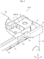
- Fig. 1 is a perspective view showing the appearance of a battery module 100 according to one embodiment of the present disclosure.
- Fig. 2 is an exploded perspective view of the battery module 100 in Fig. 1 .
- Fig. 3 is an enlarged perspective view of a module terminal 101P of the battery module 100 shown in Fig. 1 .
- Fig. 3 is a cutaway view of a module cover 25, which is a part of a housing 20 of the battery module 100 shown in Fig. 1 .
- the battery module 100 of the present embodiment has the following major features.
- the battery module 100 includes a plurality of battery cells, and busbars 10 connecting to external terminals 1p and 1n of the battery cells 1.
- One of the busbars 10 has a pair of terminal portions 11 and 12, a current-carrying portion 13 connecting the pair of terminal portions 11 and 12, and a fuse 14 is provided in the current-carrying portion 13 (see Fig. 6 and Fig. 8 , for example).
- the current-carrying portion 13 surrounds the fuse 14.
- the battery module 100 includes the plurality of battery cells 1, and a housing 20 that stores the plurality of battery cells 1.
- the plurality of battery cells 1 are lithium ion secondary batteries each having a flattened rectangular shape, and these battery cells are stacked in their thickness direction.
- the XYZ orthogonal coordinate system shown in the drawings has the X-axis parallel to the thickness direction of the battery cells 1, that is, the stacking direction of the plurality of cells 1, the Y-axis parallel to the width direction of the battery cells 1, and the Z-axis parallel to the height direction of the battery cells 1.
- Each battery cell 1 includes a flattened rectangular cell case 1a, an electrode group and electrolyte that are stored in this cell case 1a, and a pair of external terminals 1p and 1n connecting to the electrode group and disposed on the vertically upper end face of the cell case 1a.
- the external terminals 1p and 1n each have a substantially cuboid three-dimensional shape that protrudes vertically (in the Z-axis direction) from the upper end face of the cell case 1a.
- Respective resin insulating members electrically isolate between the external terminal 1p, In and the cell case 1a, and between the cell case 1a and the electrode group.
- the plurality of battery cells 1 are stacked while reversing their direction by 180° so that the positive-electrode external terminal 1p of one of mutually adjacent battery cells 1 and the negative-electrode external terminal In of the other battery cell 1 are adjacent to each other in the stacking direction (X-axis direction).
- the housing 20 has a substantially cuboid shape, having the dimension in the length direction (X-axis direction) that is larger than the dimensions in the transverse direction (Y-axis direction) and in the height direction (Z-axis direction), and holds the plurality of battery cells 1 stacked in the thickness direction.
- the housing 20 has a plurality of cell holders 21, a pair of end plates 22, a pair of side plates 23, an insulation cover 24 and a module cover 25, for example.
- the cell holders 21 are made of a resin material such as polybutylene terephthalate (PBT).
- PBT polybutylene terephthalate
- each cell holder 21 intervenes between mutually adjacent battery cells 1 of the plurality of battery cells 1 stacked in the thickness direction (X-axis direction), and holds these battery cells 1 to sandwich them from both sides in the thickness direction.
- the pair of cell holders 21 placed at both ends in the stacking direction (X-axis direction) of the plurality of battery cells 1 each have a fixing part 21a to fix an end busbar 10E described later.
- the pair of end plates 22 includes plate members made of metal.
- the pair of end plates 22 is disposed at both ends of in the stacking direction (X-axis direction) of the plurality of battery cells 1 via the pair of cell holders 21.
- Each of the end plates 22 as a pair has one face that is opposed to the plurality of battery cells 1 held at the cell holders 21.
- the other face of the end plate 22 is directed to the other side of the battery cells 1, and has a fixing part 22a.
- the end plates 22 as a pair each have the face that is opposed to the plurality of battery cells 1, and this face has a concave 22b to engage with the fixing part 21a of the corresponding cell holder 21.
- the fixing part 22a at the end plate 22 is substantially cylindrical, and a part of the cylindrical face protrudes outward from the outer face of the end plate 22.
- the fixing part 22a at the end plate 22 has a bolt hole that is bored along the center axis parallel to the height direction (Z-axis direction) of the end plate 22.
- This fixing part 22a of the end plate 22 is to fix the battery module 100 to an external mechanism, such as a vehicle or another machine.
- the concave 22b of the end plate 22 engages with the fixing part 21a of the cell holder 21 to hold the fixing part 21a of the cell holder 21.
- the pair of side plates 23 is disposed at both ends in the width direction (Y-axis direction) of the battery cells 1 via the cell holders 21.
- the side plates 23 as a pair are metal plates each having a substantially rectangular shape, and are mutually opposed at both ends of the housing 20 in the transverse direction (Y-axis direction).
- the side plates 23 as a pair are substantially oblongs, having the long-side direction, i.e., longitudinal direction in the stacking direction (X-axis direction) of the plurality of battery cells 1 and the short-side direction, i.e., transverse direction in the height direction (Z-axis direction) of the battery cells 1.
- the pair of side plates 23 are fastened at both ends in the longitudinal direction to the pair of end plates 22 by fasteners, such as rivets or bolts, and engage with recessed grooves of the cell holders 21 at both ends in the transverse direction.
- the insulation cover 24 is a plate member made of resin such as engineering plastic including PBT that has an electrical insulating property, and is opposed to the upper end face of each cell case 1a having the external terminals 1p and 1n of the battery cell 1.
- the insulation cover 24 has openings to expose the upper end faces of the external terminals 1p and 1n of the plurality of battery cells 1 and a partition wall for insulation between the external terminals 1p and 1n of the adjacent battery cells 1 and between the mutually adjacent busbars 10.
- the partition wall of the insulation cover 24 is disposed so as to surround the external terminals 1p and 1n of the battery cells 1 and the busbars 10.
- Various types of electric wiring is placed on the insulation cover 24 to connect to the battery cells 1, an electronic circuit board, and the like.
- the busbars 10 are plate members made of metal having electrical conductivity that connect the plurality of battery cells 1 and also connect these connected battery cells 1 to the module terminals 101P and 101N.
- the busbars 10 include a plurality of relay busbars 10J that connect the plurality of battery cells 1, and a pair of end busbars 10E that connect the plurality of battery cells 1, which are connected by the plurality of relay busbars 10J, to the module terminals 101P and 101N.
- the relay busbars 10J each have a pair of terminal portions 11 and 12, and a current-carrying portion 13 connecting the pair of terminal portions 11 and 12.
- the pair of terminal portions 11 and 12 of the relay busbar 10J are rectangular plate portions that are substantially parallel to the upper end faces of the external terminals 1p and 1n of the battery cell 1.
- the terminal portions 11 and 12 of the relay busbar 10J are connected by welding, for example, to the upper end faces of the external terminals 1p and In, respectively, of the plurality of battery cells 1 exposed through the openings of the insulation cover 24.
- the pair of terminal portions 11 and 12 of the relay busbar 10J may be connected to the external terminals 1p and 1n of the corresponding battery cell 1 via fasteners such as bolts or rivets.
- each relay busbar 10J is bent from the terminal portion 11 in the height direction (Z-axis direction) of the battery cell 1 to extend upward so as to be away from the battery cell 1, and is bent in the opposite direction to be connected to the other terminal portion 12. That is, the current-carrying portion 13 of the relay busbar 10J is bent in a substantially U shape in the side view in the width direction (Y-axis direction) of the battery cell 1.
- each of the plurality of relay busbars 10J is connected to the positive-electrode external terminal 1p of one of mutually adjacent battery cells 1 in the stacking direction and the negative-electrode external terminal In of the other battery cell 1, so as to connect the plurality of battery cells 1 in series.
- the end busbars 10E each have a pair of terminal portions 11 and 12, and a current-carrying portion 13 connecting the pair of terminal portions 11 and 12.
- the terminal portions 11 of the pair of end busbars 10E are a rectangular plate portion that is substantially parallel to the upper end faces of the external terminals 1p and 1n of the battery cells 1.
- the other terminal portions 12 of the pair of end busbars 10E are a rectangular plate portion that is substantially parallel to the one terminal portion 11, and is placed at a position farther away from the battery cell 1 than the one terminal portion 11 in the height direction (Z-axis direction) of the battery cells 1.
- One of the pair of end busbars 10E has the terminal portion 11 connected to the positive-electrode external terminal 1p of the battery cell 1 placed at one end in the stacking direction of the plurality of battery cells 1.
- the other of the pair of end busbars 10E has the terminal portion 11 connected to the negative-electrode external terminal In of the battery cell 1 placed at the other end in the stacking direction of the plurality of battery cells 1.
- These terminal portions 11 of the pair of end busbars 10E are connected by welding, for example, to the upper end faces of the external terminals 1p and 1n of the battery cells 1, respectively.
- the end busbar 10E connected to the negative-electrode external terminal In of the battery cell 1 has a current-carrying portion 13 that is bent from the terminal portion 11 in the height direction (Z-axis direction) of the battery cell 1 to extend upward to move away from the battery cell 1, and is connected to the other terminal portion 12.
- the end busbar 10E connected to the positive-electrode external terminal 1p of the battery cell 1 has a current-carrying portion 13 that is bent into a tubular shape extending in one direction (X-axis direction) so as to surround a fuse 14 disposed inside (see Fig. 6 and Fig. 8 , for example). Details of the end busbar 10E having the current-carrying portion 13 surrounding the fuse 14, which is a feature of the battery module 100 of the present embodiment, will be described later with reference to Figs 4 to 9 .
- the terminal portions 12 of the pair of end busbars 10E are fastened and fixed to the fixing portions 21a of the cell holders 21 at both ends in the stacking direction of the battery cells 1 by fasteners such as bolts and nuts.
- the fixing portions 21a of these cell holder 21 engage with the concaves 22b of the pair of end plates 22 for fixing. With this configuration, the terminal portions 12 of the pair of end busbars 10E are fixed to the pair of end plates 22 via the fixing portions 21a of the cell holders 21.
- the battery module 100 of the present embodiment includes the pair of end plates 22 placed at both ends in the stacking direction of the plurality of battery cells 1 each having a flattened rectangular shape and stacked in the thickness direction.
- the end busbars 10E are fixed to the end plates 22.
- the terminal portions 12 of the pair of end busbars 10E are connected to the positive-electrode module terminal 101P and the negative-electrode module terminal 101N of the battery module 100, respectively, and are a part of the module terminals 101P and 101N.
- These positive-electrode module terminal 101P and negative-electrode module terminal 101N are external terminals of the battery module 100, and are connected to an external electric device via wiring, for example.
- the battery module 100 of the present embodiment is connected to an external electric device such as a generator or a motor via the positive-electrode module terminal 101P and the negative-electrode module terminal 101N. Receiving electricity from the external electric device via the module terminals 101P and 101N, the plurality of battery cells 1 of the battery module 100 will be charged.
- the battery module 100 can also supply electricity from the plurality of charged battery cells 1 to the external electrical device via the plurality of relay busbars 10J, the pair of end busbars 10E, and the pair of module terminals 101P and 101N.
- Fig. 4 is a perspective view of the end busbar 10E constituting the module terminal 101P shown in Fig. 3 .
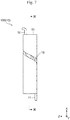
- Fig. 5 is a developed view of the end busbar 10E shown in Fig. 4 .
- Fig. 6 is a plan view of the end busbar 10E shown in Fig. 4 .
- Fig. 7 is a front view of the end busbar 10E shown in Fig. 4 .
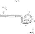
- Fig. 8 is a cross-sectional view of the end busbar 10E taken along the line VIII-VIII of Fig. 6 .
- Fig. 9 is a cross-sectional view of the end busbar 10E taken along the line IX-IX of Fig. 7 .
- the battery module 100 of the present embodiment includes a plurality of battery cells 1, and busbars 10 connecting to external terminals 1p and 1n of the battery cells 1.
- One of the busbars 10 has a pair of terminal portions 11 and 12, a current-carrying portion 13 connecting the pair of terminal portions 11 and 12, and a fuse 14 provided in the current-carrying portion 13.
- the current-carrying portion 13 surrounds the fuse 14.
- the battery module 100 of the present embodiment is configured so that only one of the end busbar 10E of the pair of end busbars 10E in the plurality of busbars 10 includes the fuse 14.
- the battery module 100 of the present embodiment includes a pair of module terminals 101P and 101N to be connected to an external device as described above.
- the busbars 10 include a plurality of relay busbars 10J that connect the plurality of battery cells 1 in series, and a pair of end busbars 10E that connect the plurality of battery cells 1, which are connected in series by the plurality of relay busbars 10J, to the pair of module terminals 101P and 101N.
- the fuse 14 is placed at one of the end busbars 10E.
- the other busbars 10 except for the one end busbar 10E do not include the fuse 14.
- the busbar 10 including the fuse 14 is not limited to the end busbars 10E. That is, the fuse 14 may be provided in at least one of the plurality of relay busbars 10J included in the plurality of busbars 10, not in the end busbars 10E.
- the pair of terminal portions 11 and 12 of each busbar 10 is provided at one end and the other end in a first direction (X-axis direction).
- the current-carrying portion 13 has one end connected to the pair of terminal portions 11 and 12 and the other end provided with the fuse 14, in a second direction (Y-axis direction) orthogonal to the first direction.
- the fuse 14 is placed inside the current-carrying portion 13 bent in a tubular shape extending in the first direction.
- the first direction is the stacking direction of the battery cells 1, that is, the thickness direction of the battery cells 1
- the second direction is the width direction of the battery cells 1.
- the current-carrying portion 13 is spirally wound around the fuse 14 for one or more laps in a cross section perpendicular to the first direction (X-axis direction). Specifically, the current-carrying portion 13 extends in the second direction from one end of the terminal portion 11 in the second direction (Y-axis direction), and is bent away from the battery cell 1 in the third direction (Z-axis direction) orthogonal to the first direction and the second direction.
- the third direction is the height direction of the battery cells 1.
- the current-carrying portion 13 which extends in the second direction (Y-axis direction) from one end of the terminal portion 11 and is bent in the third direction (Z-axis direction), is further bent into a cylindrical shape having a central axis parallel to the first direction (X-axis direction).
- the cylindrically bent current-carrying portion 13 extends to a position facing the one end of the current-carrying portion 13 connected to the terminal portion 11 while keeping a distance in the third direction from the one end.
- the current-carrying portion 13 extends further in the second direction from the position, and has the tip portion located inside the cylindrically bent portion.
- the fuse 14 is provided at the tip portion of current-carrying portion 13.
- the current-carrying portion 13 extends toward the battery cell 1 in the third direction (Z-axis direction), from one end of the terminal portion 12 in the second direction (Y-axis direction), and extends in the second direction and outward in the width direction of the battery cells 1.
- the current-carrying portion 13 is then bent away from the battery cells 1 in the third direction (Z-axis direction).
- the current-carrying portion 13 is further bent into a cylindrical shape having a central axis parallel to the first direction (X-axis direction), and extends to a position facing the part of the current-carrying portion 13 parallel to the first direction and the second direction while keeping a distance from the part in the third direction.
- the current-carrying portion 13 extends further in the second direction from the position, and has the tip portion located inside the cylindrically bent portion.
- the fuse 14 in provided at the tip portion of the current-carrying portion 13.
- the current-carrying portion 13 in a state unfold to the flat surface has a slit 15 extending from one end between the pair of terminal portions 11, 12 to the fuse 14, in the second direction (Y-axis direction).
- a cross-sectional area of the current-carrying portion 13 in the cross section orthogonal to the first direction (X-axis direction) becomes smallest at the fuse 14.
- the slit 15 extends linearly in a direction intersecting the first and the second directions, for example.
- the slit 15 may extend in a stepped pattern alternately in the second direction and the first direction.
- the end busbars 10E can be entirely made of the same type of metal.
- the current-carrying portion 13 may have a first part 13a including the fuse 14, and a second part 13b connected to the first part 13a and the pair of terminal portions 11 and 12, for example.
- the melting point of a first metal which is the material of the first part 13a
- the end busbars 10E in the battery module 100 of the present embodiment may include a clad material made of aluminum and copper, for example.
- the material of the first part 13a of the current-carrying portion 13 may be aluminum
- the material of the second part 13b of the current-carrying portion 13 may be copper.
- the battery module 100 of the present embodiment can supply electricity from the plurality of charged battery cells 1 to the external electrical device via the plurality of relay busbars 10J, the pair of end busbars 10E, and the pair of module terminals 101P and 101N. If an external short circuit occurs in the plurality of cells 1, for example, due to some abnormality, an abnormally large current flows in the fuse 14 of the end busbar 10E, and the fuse 14 blows. This allows the current path of the abnormally large current to be interrupted.
- the battery module 100 of the present embodiment includes the plurality of battery cells 1, and the busbars 10 connecting to the external terminals 1p and 1n of the battery cells 1.
- One of the busbars 10 has a pair of terminal portions 11 and 12, a current-carrying portion 13 connecting the pair of terminal portions 11 and 12, and a fuse 14 is provided in the current-carrying portion 13.
- the current-carrying portion 13 surrounds the fuse 14.
- the current-carrying portion 13 surrounding the fuse 14 prevents the molten metal from scattering when the fuse 14 blows. This prevents the molten metal at high temperatures from adhering to the resin members such as the cell holders 21, the insulation cover 24, and the module cover 25, and so enhances the safety of the battery module 100.
- the current-carrying portion 13 as a part of the busbar 10 covers the fuse 14 as a part of the busbar 10, and so this configuration does not require another additional member for covering the fuse 14 in the busbar 10.
- the pair of terminal portions 11 and 12 are provided at one end and the other end in the first direction (X-axis direction).
- the current-carrying portion 13 In the state of unfolded to the flat surface, in the second direction (Y-axis direction) orthogonal to the first direction, the current-carrying portion 13 has one end connected to the pair of terminal portions 11 and 12, and the other end provided with the fuse 14.
- the fuse 14 is placed inside the current-carrying portion 13 bent in a tubular shape extending in the first direction.
- the fuse 14 is placed inside the tubular current-carrying portion 13 connecting the pair of terminal portions 11 and 12, and so the current-carrying portion 13 surrounds the fuse 14 provided in the current-carrying portion 13.
- the current-carrying portion 13 is bent in the second direction (Y-axis direction) from the end opposite to the pair of terminal portions 11 and 12 toward the pair of terminal portions 11 and 12 into a tubular shape having a central axis parallel to the first direction (X-axis direction).
- the current-carrying portion 13 surrounds the fuse 14 provided in the current-carrying portion 13 at least in a cross section orthogonal to the first direction, so that the current-carrying portion 13 covers the fuse 14.
- Such bending of the current-carrying portion 13 into a tubular shape extending in the stacking direction (X-axis direction) of the battery cells 1 in which the pair of terminal portions 11 and 12 are placed side by side reduces the dimension of the current-carrying portion 13 in the width direction (Y-axis direction) of the battery cell 1, and so makes the battery module 100 compact.
- the current-carrying portion 13 is spirally wound around the fuse 14 for one or more laps in a cross section perpendicular to the first direction (X-axis direction).
- This configuration allows the fuse 14 to be covered without gap at an angle of 360 degrees or more around the fuse 14, at least in a cross section orthogonal to the first direction.
- the current-carrying portion 13 in a state unfolded to a flat surface has the slit 15 extending from one end in the second direction (Y-axis direction) between the pair of terminal portions 11, 12 to the fuse 14.
- a cross-sectional area of the current-carrying portion 13 in the cross section orthogonal to the first direction (X-axis direction) becomes smallest at the fuse 14. If an abnormally large current flows through the current-carrying portion 13, which is the current path between the pair of terminal portions 11 and 12, the fuse 14 can be selectively blown to interrupt the current path.
- the slit 15 in the current-carrying portion 13 in a state unfolded on a plane parallel to the first direction (X-axis direction) and the second direction (Y-direction), the slit 15 extends linearly in a direction intersecting the first and the second directions.
- this configuration allows the inner wall face of the slit 15 to receive the molten metal scattered in the direction orthogonal to the first direction. This makes it possible to more reliably prevent the molten metal due to the blowing of the fuse 14 from passing through the slit 15 and scattering to the outside of the cylindrical current-carrying portion 13 surrounding the fuse 14.
- the battery module 100 of the present embodiment may be configured so that, in the state of the current-carrying portion 13 is unfolded to the flat surface, the slit 15 extends in a stepped pattern alternately in the second direction (Y-axis direction) and the first direction (X-axis direction).
- this configuration also allows the inner wall face of the slit 15 to receive the molten metal scattered in the direction orthogonal to the first direction. This makes it possible to more reliably prevent the molten metal from passing through the slit 15 and scattering to the outside of the cylindrical current-carrying portion 13.
- the battery module 100 of the present embodiment is configured so that the current-carrying portion 13 may have the first part 13a including the fuse 14 and the second part 13b connected to the first part 13a and the pair of terminal portions 11 and 12 as described above.
- the melting point of a first metal which is the material of the first part 13a
- a second metal which is the material of the second part 13b as described above.
- the molten metal of the fuse 14 included in the first part 13a after blowing attached to the second part 13b of the current-carrying portion 13 does not cause melting or deformation of the second part 13b of the current-carrying portion 13. This further improves the safety of the battery module 100.
- the battery module 100 of the present embodiment includes the pair of module terminals 101P and 101N to be connected to an external device as described above.
- the busbars 10 include the plurality of relay busbars 10J that connect the plurality of battery cells 1 in series, and the pair of end busbars 10E that connect the plurality of battery cells 1, which are connected in series by the plurality of relay busbars 10J, to the pair of module terminals 101P and 101N.
- the fuse 14 is placed at one of the end busbars 10E.
- one of the end busbar 10E connecting the plurality of battery cells 1 connected in series to the module terminals 101P and 101N includes the fuse 14, and this configuration safely and reliably interrupts the current path of the battery module 100 through which high-voltage and high current flows in an abnormal condition.
- the fuse 14 is provided in one of the end busbar 10E at the ends in the stacking direction of the plurality of battery cells 1, and this makes it possible to easily keep a space for providing the current-carrying portion 13 surrounding the fuse 14. This improves the degree of freedom in designing of the battery module 100.
- the battery module 100 of the present embodiment includes the pair of end plates 22 placed at both ends in the stacking direction of the plurality of battery cells 1 each having a flattened rectangular shape and stacked in the thickness direction.
- the end busbars 10E are fixed to the end plates 22. This configuration allows the fixation of the end busbars 10E to the end plates 22 via the fixing parts 21a of the cell holders 21, for example, and so configures the module terminals 101P and 101N with the pair of end busbars 10E.
- the present embodiment provides the battery module 100 that has better safety than conventional battery modules.
- the battery module of the present disclosure is not limited to the structure of the battery module 100 according to the present embodiment.
- the battery module 100 of the present embodiment is configured so that only one of the pair of end busbars 10E in the plurality of busbars 10 includes the fuse 14.
- the busbar 10 including the fuse 14 is not limited to the end busbar 10E. That is, instead of the end busbar 10E, at least one of the relay busbars 10J may include the fuse 14 surrounded by the current-carrying portion 13.
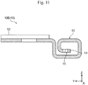
- Fig. 10 is a perspective view of a modified example of the end busbar 10E in Fig. 4 .
- Fig. 11 is a cross-sectional view of the end busbar 10E shown in Fig. 10 according to the modified example of the battery module 100, which is a view corresponding to Fig. 8 .
- the battery module of this modified example shown in Figs 5 , 10 and 11 includes a current-carrying portion 13 that has a rectangular tubular shape bent at an angle of approximately 90 degrees at a plurality of positions.
- the current-carrying portion 13 is spirally wound around the fuse 14 for one or more laps.
- the battery module of this modified example having such a configuration can also obtain the same effects as the battery module 100 according to the above-described embodiment.
- the current-carrying portion 13 in the battery module according to this modified example may have a closing portion that closes the openings at both ends in the first direction (X-axis direction).
- the closing portion 16 is formed as a tongue-shaped or tab-shaped convex at both ends of the current-carrying portion 13 in the first direction in the state unfolded to the flat surface.
- This closing portion 16 has a planar shape that corresponds to a cross-sectional shape orthogonal to the first direction of the current-carrying portion 13 bent in a tubular shape, for example. That is, when the cross-sectional shape of the current-carrying portion 13 bent into a tubular shape is approximately rectangular, the planar shape of the closing portion 16 can be approximately rectangular. When the cross-sectional shape of the current-carrying portion 13 bent into a tubular shape is approximately circular, the planar shape of the closing portion 16 can be approximately circular.
- the closing portion 16 After bending the current-carrying portion 13 in the state unfolded to the plane into a tubular shape, the closing portion 16 is bent in the third direction (Z-axis direction) orthogonal to the first direction (X-axis direction) and the second direction (Y-axis direction). As a result, the closing portion 16 becomes approximately orthogonal to the first direction and becomes approximately parallel to the second and third directions, and faces the openings at both ends of the tubular current-carrying portion 13 extending in the first direction to close the openings.
- this configuration allows the closing portion 16 to receive the molten metal scattered in the direction toward the openings at both ends of the tubular current-carrying portion 13. This makes it possible to more reliably prevent the molten metal due to the blowing of the fuse 14 from scattering to the outside through the openings at both ends of the tubular current-carrying portion 13, and so further enhances the safety of the battery module.
Abstract
Provided is a battery module capable of improving the safety as compared with the conventional one. The battery module includes a plurality of battery cells, and busbars 10 connecting to external terminals of the battery cells. The busbars 10 include a busbar, the busbar has a pair of terminal portions 11 and 12, a current-carrying portion 13 connecting the pair of terminal portions 11 and 12, and a fuse 14 placed at the current-carrying portion 13. The current-carrying portion 13 surrounds the fuse 14.
Description
- The present disclosure relates to battery modules each having a plurality of battery cells.
- Conventionally inventions about an electric storage device including a plurality of battery cells and busbars have been known (see Patent Literature 1). The electric storage device according to Patent Literature 1 includes: a first battery cell block including a plurality of battery cells; a second battery cell block including other plurality of battery cells; and a busbar electrically connecting the plurality of battery cells in the first battery cell block and the plurality of battery cells in the second battery cell block.
- The busbar has a first busbar part, a second busbar part, and a third busbar part. The first busbar part connects to one of the positive electrodes and the negative electrodes of the plurality of battery cells in the first battery cell block via fuses. The second busbar part connects to the other of the positive electrodes and the negative electrodes of the plurality of battery cells in the second battery cell block. The third busbar part connects the first busbar part and the second busbar part.
- The third busbar part includes a first portion adjacent to the first busbar part and a second portion closer to the second busbar part than the first portion. The second portion radiates heat more than the first portion does (see this literature, claim 1, for example).
- According to this structure, in the third busbar part, the first portion closer to the fuse radiates less heat, and the second portion away from the fuse radiates more heat. This means that the first portion closer to the fuse is not restricted for the fuse function such as a current value during the current interruption, and the fuse therefore fulfills the original function. The second portion away from the fuse radiates more heat. This reduces heat generated at the fuse effectively due to the radiative effect so as to suppress the transmission of the heat to other battery cells (see this literature, paragraph 0011, for example).
- This conventional electric storage device has a plurality of openings in a flat plate arranged above the positive electrodes. This flat plate has a positive-electrode tab extending in an L shape on the inner peripheral edge of each opening, and the tip of this positive-electrode tab is provided with a fuse. The fuse has a connecting portion at the tip, and the connecting portion is connected to the positive electrode of the battery cell by welding, for example. The fuse blows when an overcurrent exceeding a predetermined value flows (see this literature, paragraphs 0022-0023,
Fig. 3 , for example). - Patent Literature 1:
JP 2016-66455 A - In the above-mentioned conventional electric storage device, the fuses are exposed at a position facing the resin case accommodating the battery cells. When a fuse blows, the molten metal may scatter and adhere to the resin case, which may degrade the safety of the electric storage device.
- The present disclosure provides a battery module capable of improving the safety as compared with the conventional ones.
- A battery module according to one aspect of the present disclosure includes: a plurality of battery cells; and busbars connected to external terminals of the battery cells. The busbars include a busbar, the busbar has a pair of terminal portions, a current-carrying portion connecting the pair of terminal portions, and a fuse provided in the current-carrying portion. The current-carrying portion surrounds the fuse.
- According to the above aspect of the present disclosure, a part of the current-carrying portion, which is a path of the current flowing between the pair of terminal portions of the busbar, surrounds the fuse provided in the current-carrying portion. This configuration prevents scattering of the molten metal when the fuse blows. The present disclosure therefore provides a battery module capable of improving the safety as compared with the conventional ones.
-
-
Fig. 1 is a perspective view of a battery module according to one embodiment of the present disclosure. -
Fig. 2 is an exploded perspective view of the battery module inFig. 1 . -
Fig. 3 is an enlarged perspective view of a module terminal of the battery module inFig. 1 . -
Fig. 4 is a perspective view of the busbar constituting the module terminal shown inFig. 3 . -
Fig. 5 is a developed view of the busbar shown inFig. 4 . -
Fig. 6 is a plan view of the busbar shown inFig. 4 . -
Fig. 7 is a front view of the busbar shown inFig. 4 . -
Fig. 8 is a cross-sectional view of the busbar taken along the line VIII-VIII ofFig. 6 . -
Fig. 9 is a cross-sectional view of the busbar taken along the line IX-IX ofFig. 7 . -
Fig. 10 is a perspective view of a modified example of the busbar inFig. 4 . -
Fig. 11 is a cross-sectional view of the busbar shown inFig. 10 , which is a view corresponding toFig. 8 . - The following describes some embodiments of a battery module according to the present disclosure, with reference to the drawings. The following may describe various parts of the battery module while referring to the orthogonal coordinate system having X-axis, Y-axis, and Z-axis shown in the drawings. In the following descriptions, directional terms, such as upper, lower, left, right, vertical, horizontal, front, and rear, are used for convenience to explain various parts of the battery module shown in the drawings, and these terms do not limit the posture of the battery module and the arrangement of the parts.
-
Fig. 1 is a perspective view showing the appearance of abattery module 100 according to one embodiment of the present disclosure.Fig. 2 is an exploded perspective view of thebattery module 100 inFig. 1 .Fig. 3 is an enlarged perspective view of amodule terminal 101P of thebattery module 100 shown inFig. 1 .Fig. 3 is a cutaway view of amodule cover 25, which is a part of ahousing 20 of thebattery module 100 shown inFig. 1 . - Although the details are described later, the
battery module 100 of the present embodiment has the following major features. Thebattery module 100 includes a plurality of battery cells, andbusbars 10 connecting toexternal terminals 1p and 1n of the battery cells 1. One of thebusbars 10 has a pair ofterminal portions portion 13 connecting the pair ofterminal portions fuse 14 is provided in the current-carrying portion 13 (seeFig. 6 andFig. 8 , for example). The current-carryingportion 13 surrounds thefuse 14. - The following describes various parts of the
battery module 100 of the present embodiment in details. Thebattery module 100 includes the plurality of battery cells 1, and ahousing 20 that stores the plurality of battery cells 1. In one example, the plurality of battery cells 1 are lithium ion secondary batteries each having a flattened rectangular shape, and these battery cells are stacked in their thickness direction. The XYZ orthogonal coordinate system shown in the drawings has the X-axis parallel to the thickness direction of the battery cells 1, that is, the stacking direction of the plurality of cells 1, the Y-axis parallel to the width direction of the battery cells 1, and the Z-axis parallel to the height direction of the battery cells 1. - Each battery cell 1 includes a flattened
rectangular cell case 1a, an electrode group and electrolyte that are stored in thiscell case 1a, and a pair ofexternal terminals 1p and 1n connecting to the electrode group and disposed on the vertically upper end face of thecell case 1a. Theexternal terminals 1p and 1n each have a substantially cuboid three-dimensional shape that protrudes vertically (in the Z-axis direction) from the upper end face of thecell case 1a. Respective resin insulating members electrically isolate between the external terminal 1p, In and thecell case 1a, and between thecell case 1a and the electrode group. The plurality of battery cells 1 are stacked while reversing their direction by 180° so that the positive-electrode external terminal 1p of one of mutually adjacent battery cells 1 and the negative-electrode external terminal In of the other battery cell 1 are adjacent to each other in the stacking direction (X-axis direction). - The
housing 20 has a substantially cuboid shape, having the dimension in the length direction (X-axis direction) that is larger than the dimensions in the transverse direction (Y-axis direction) and in the height direction (Z-axis direction), and holds the plurality of battery cells 1 stacked in the thickness direction. Specifically, thehousing 20 has a plurality ofcell holders 21, a pair ofend plates 22, a pair ofside plates 23, aninsulation cover 24 and amodule cover 25, for example. - In one example, the
cell holders 21 are made of a resin material such as polybutylene terephthalate (PBT). In one example, eachcell holder 21 intervenes between mutually adjacent battery cells 1 of the plurality of battery cells 1 stacked in the thickness direction (X-axis direction), and holds these battery cells 1 to sandwich them from both sides in the thickness direction. In one example, the pair ofcell holders 21 placed at both ends in the stacking direction (X-axis direction) of the plurality of battery cells 1 each have a fixingpart 21a to fix anend busbar 10E described later. - In one example, the pair of
end plates 22 includes plate members made of metal. The pair ofend plates 22 is disposed at both ends of in the stacking direction (X-axis direction) of the plurality of battery cells 1 via the pair ofcell holders 21. Each of theend plates 22 as a pair has one face that is opposed to the plurality of battery cells 1 held at thecell holders 21. The other face of theend plate 22 is directed to the other side of the battery cells 1, and has a fixingpart 22a. Theend plates 22 as a pair each have the face that is opposed to the plurality of battery cells 1, and this face has a concave 22b to engage with the fixingpart 21a of thecorresponding cell holder 21. - The fixing
part 22a at theend plate 22 is substantially cylindrical, and a part of the cylindrical face protrudes outward from the outer face of theend plate 22. The fixingpart 22a at theend plate 22 has a bolt hole that is bored along the center axis parallel to the height direction (Z-axis direction) of theend plate 22. This fixingpart 22a of theend plate 22 is to fix thebattery module 100 to an external mechanism, such as a vehicle or another machine. The concave 22b of theend plate 22 engages with the fixingpart 21a of thecell holder 21 to hold the fixingpart 21a of thecell holder 21. - The pair of
side plates 23 is disposed at both ends in the width direction (Y-axis direction) of the battery cells 1 via thecell holders 21. In one example, theside plates 23 as a pair are metal plates each having a substantially rectangular shape, and are mutually opposed at both ends of thehousing 20 in the transverse direction (Y-axis direction). Theside plates 23 as a pair are substantially oblongs, having the long-side direction, i.e., longitudinal direction in the stacking direction (X-axis direction) of the plurality of battery cells 1 and the short-side direction, i.e., transverse direction in the height direction (Z-axis direction) of the battery cells 1. The pair ofside plates 23 are fastened at both ends in the longitudinal direction to the pair ofend plates 22 by fasteners, such as rivets or bolts, and engage with recessed grooves of thecell holders 21 at both ends in the transverse direction. - The
insulation cover 24 is a plate member made of resin such as engineering plastic including PBT that has an electrical insulating property, and is opposed to the upper end face of eachcell case 1a having theexternal terminals 1p and 1n of the battery cell 1. Theinsulation cover 24 has openings to expose the upper end faces of theexternal terminals 1p and 1n of the plurality of battery cells 1 and a partition wall for insulation between theexternal terminals 1p and 1n of the adjacent battery cells 1 and between the mutuallyadjacent busbars 10. In one example, the partition wall of theinsulation cover 24 is disposed so as to surround theexternal terminals 1p and 1n of the battery cells 1 and thebusbars 10. Various types of electric wiring is placed on theinsulation cover 24 to connect to the battery cells 1, an electronic circuit board, and the like. - The
busbars 10 are plate members made of metal having electrical conductivity that connect the plurality of battery cells 1 and also connect these connected battery cells 1 to themodule terminals busbars 10 include a plurality ofrelay busbars 10J that connect the plurality of battery cells 1, and a pair ofend busbars 10E that connect the plurality of battery cells 1, which are connected by the plurality ofrelay busbars 10J, to themodule terminals - The
relay busbars 10J each have a pair ofterminal portions portion 13 connecting the pair ofterminal portions terminal portions relay busbar 10J are rectangular plate portions that are substantially parallel to the upper end faces of theexternal terminals 1p and 1n of the battery cell 1. Theterminal portions relay busbar 10J are connected by welding, for example, to the upper end faces of the external terminals 1p and In, respectively, of the plurality of battery cells 1 exposed through the openings of theinsulation cover 24. The pair ofterminal portions relay busbar 10J may be connected to theexternal terminals 1p and 1n of the corresponding battery cell 1 via fasteners such as bolts or rivets. - The current-carrying
portion 13 of eachrelay busbar 10J is bent from theterminal portion 11 in the height direction (Z-axis direction) of the battery cell 1 to extend upward so as to be away from the battery cell 1, and is bent in the opposite direction to be connected to the otherterminal portion 12. That is, the current-carryingportion 13 of therelay busbar 10J is bent in a substantially U shape in the side view in the width direction (Y-axis direction) of the battery cell 1. In one example, each of the plurality ofrelay busbars 10J is connected to the positive-electrode external terminal 1p of one of mutually adjacent battery cells 1 in the stacking direction and the negative-electrode external terminal In of the other battery cell 1, so as to connect the plurality of battery cells 1 in series. - Similarly to the
relay busbars 10J, theend busbars 10E each have a pair ofterminal portions portion 13 connecting the pair ofterminal portions terminal portions 11 of the pair ofend busbars 10E are a rectangular plate portion that is substantially parallel to the upper end faces of theexternal terminals 1p and 1n of the battery cells 1. The otherterminal portions 12 of the pair ofend busbars 10E are a rectangular plate portion that is substantially parallel to the oneterminal portion 11, and is placed at a position farther away from the battery cell 1 than the oneterminal portion 11 in the height direction (Z-axis direction) of the battery cells 1. - One of the pair of
end busbars 10E has theterminal portion 11 connected to the positive-electrode external terminal 1p of the battery cell 1 placed at one end in the stacking direction of the plurality of battery cells 1. The other of the pair ofend busbars 10E has theterminal portion 11 connected to the negative-electrode external terminal In of the battery cell 1 placed at the other end in the stacking direction of the plurality of battery cells 1. Theseterminal portions 11 of the pair ofend busbars 10E are connected by welding, for example, to the upper end faces of theexternal terminals 1p and 1n of the battery cells 1, respectively. - Of the pair of
end busbars 10E, theend busbar 10E connected to the negative-electrode external terminal In of the battery cell 1 has a current-carryingportion 13 that is bent from theterminal portion 11 in the height direction (Z-axis direction) of the battery cell 1 to extend upward to move away from the battery cell 1, and is connected to the otherterminal portion 12. Of the pair ofend busbars 10E, theend busbar 10E connected to the positive-electrode external terminal 1p of the battery cell 1 has a current-carryingportion 13 that is bent into a tubular shape extending in one direction (X-axis direction) so as to surround afuse 14 disposed inside (seeFig. 6 andFig. 8 , for example). Details of theend busbar 10E having the current-carryingportion 13 surrounding thefuse 14, which is a feature of thebattery module 100 of the present embodiment, will be described later with reference toFigs 4 to 9 . - The
terminal portions 12 of the pair ofend busbars 10E are fastened and fixed to the fixingportions 21a of thecell holders 21 at both ends in the stacking direction of the battery cells 1 by fasteners such as bolts and nuts. The fixingportions 21a of thesecell holder 21 engage with the concaves 22b of the pair ofend plates 22 for fixing. With this configuration, theterminal portions 12 of the pair ofend busbars 10E are fixed to the pair ofend plates 22 via the fixingportions 21a of thecell holders 21. - In this way, the
battery module 100 of the present embodiment includes the pair ofend plates 22 placed at both ends in the stacking direction of the plurality of battery cells 1 each having a flattened rectangular shape and stacked in the thickness direction. Theend busbars 10E are fixed to theend plates 22. In other words, theterminal portions 12 of the pair ofend busbars 10E are connected to the positive-electrode module terminal 101P and the negative-electrode module terminal 101N of thebattery module 100, respectively, and are a part of themodule terminals electrode module terminal 101P and negative-electrode module terminal 101N are external terminals of thebattery module 100, and are connected to an external electric device via wiring, for example. - That is, the
battery module 100 of the present embodiment is connected to an external electric device such as a generator or a motor via the positive-electrode module terminal 101P and the negative-electrode module terminal 101N. Receiving electricity from the external electric device via themodule terminals battery module 100 will be charged. Thebattery module 100 can also supply electricity from the plurality of charged battery cells 1 to the external electrical device via the plurality ofrelay busbars 10J, the pair ofend busbars 10E, and the pair ofmodule terminals - Referring to
Figs 4 to 9 , the following describes the feature of thebattery module 100 of the present embodiment in detail.Fig. 4 is a perspective view of theend busbar 10E constituting themodule terminal 101P shown inFig. 3 .Fig. 5 is a developed view of theend busbar 10E shown inFig. 4 .Fig. 6 is a plan view of theend busbar 10E shown inFig. 4 .Fig. 7 is a front view of theend busbar 10E shown inFig. 4 .Fig. 8 is a cross-sectional view of theend busbar 10E taken along the line VIII-VIII ofFig. 6 .Fig. 9 is a cross-sectional view of theend busbar 10E taken along the line IX-IX ofFig. 7 . - As described above, the
battery module 100 of the present embodiment includes a plurality of battery cells 1, andbusbars 10 connecting toexternal terminals 1p and 1n of the battery cells 1. One of thebusbars 10 has a pair ofterminal portions portion 13 connecting the pair ofterminal portions fuse 14 provided in the current-carryingportion 13. The current-carryingportion 13 surrounds thefuse 14. - The
battery module 100 of the present embodiment is configured so that only one of theend busbar 10E of the pair ofend busbars 10E in the plurality ofbusbars 10 includes thefuse 14. Specifically, thebattery module 100 of the present embodiment includes a pair ofmodule terminals busbars 10 include a plurality ofrelay busbars 10J that connect the plurality of battery cells 1 in series, and a pair ofend busbars 10E that connect the plurality of battery cells 1, which are connected in series by the plurality ofrelay busbars 10J, to the pair ofmodule terminals fuse 14 is placed at one of theend busbars 10E. - In other words, in the
battery module 100 of this embodiment, theother busbars 10 except for the oneend busbar 10E do not include thefuse 14. Thebusbar 10 including thefuse 14 is not limited to theend busbars 10E. That is, thefuse 14 may be provided in at least one of the plurality ofrelay busbars 10J included in the plurality ofbusbars 10, not in theend busbars 10E. - In the
battery module 100 of the present embodiment, the pair ofterminal portions busbar 10 is provided at one end and the other end in a first direction (X-axis direction). In a state unfold to a flat surface as shown inFig. 5 , the current-carryingportion 13 has one end connected to the pair ofterminal portions fuse 14, in a second direction (Y-axis direction) orthogonal to the first direction. As shown inFigs 4 and6 to 9, thefuse 14 is placed inside the current-carryingportion 13 bent in a tubular shape extending in the first direction. In one example, the first direction is the stacking direction of the battery cells 1, that is, the thickness direction of the battery cells 1, and the second direction is the width direction of the battery cells 1. - In the
battery module 100 of the present embodiment, the current-carryingportion 13 is spirally wound around thefuse 14 for one or more laps in a cross section perpendicular to the first direction (X-axis direction). Specifically, the current-carryingportion 13 extends in the second direction from one end of theterminal portion 11 in the second direction (Y-axis direction), and is bent away from the battery cell 1 in the third direction (Z-axis direction) orthogonal to the first direction and the second direction. In one example, the third direction is the height direction of the battery cells 1. - The current-carrying
portion 13, which extends in the second direction (Y-axis direction) from one end of theterminal portion 11 and is bent in the third direction (Z-axis direction), is further bent into a cylindrical shape having a central axis parallel to the first direction (X-axis direction). The cylindrically bent current-carryingportion 13 extends to a position facing the one end of the current-carryingportion 13 connected to theterminal portion 11 while keeping a distance in the third direction from the one end. The current-carryingportion 13 extends further in the second direction from the position, and has the tip portion located inside the cylindrically bent portion. Thefuse 14 is provided at the tip portion of current-carryingportion 13. - The current-carrying
portion 13 extends toward the battery cell 1 in the third direction (Z-axis direction), from one end of theterminal portion 12 in the second direction (Y-axis direction), and extends in the second direction and outward in the width direction of the battery cells 1. The current-carryingportion 13 is then bent away from the battery cells 1 in the third direction (Z-axis direction). The current-carryingportion 13 is further bent into a cylindrical shape having a central axis parallel to the first direction (X-axis direction), and extends to a position facing the part of the current-carryingportion 13 parallel to the first direction and the second direction while keeping a distance from the part in the third direction. The current-carryingportion 13 extends further in the second direction from the position, and has the tip portion located inside the cylindrically bent portion. Thefuse 14 in provided at the tip portion of the current-carryingportion 13. - In the
battery module 100 of the present embodiment, the current-carryingportion 13 in a state unfold to the flat surface has aslit 15 extending from one end between the pair ofterminal portions fuse 14, in the second direction (Y-axis direction). With this configuration, a cross-sectional area of the current-carryingportion 13 in the cross section orthogonal to the first direction (X-axis direction) becomes smallest at thefuse 14. - In the state the current-carrying
portion 13 is unfolded on a plane (XY plane) parallel to the first direction (X-axis direction) and the second direction (Y-direction), theslit 15 extends linearly in a direction intersecting the first and the second directions, for example. In another example, in the state the current-carryingportion 13 is unfolded on the plane, theslit 15 may extend in a stepped pattern alternately in the second direction and the first direction. With these configurations, thefuse 14 is off-centered to the side of theterminal portion 12 between theterminal portions - In the
battery module 100 of the present embodiment, theend busbars 10E can be entirely made of the same type of metal. The current-carryingportion 13 may have afirst part 13a including thefuse 14, and asecond part 13b connected to thefirst part 13a and the pair ofterminal portions first part 13a, is preferably lower than the melting point of a second metal, which is the material of thesecond part 13b. That is, theend busbars 10E in thebattery module 100 of the present embodiment may include a clad material made of aluminum and copper, for example. In this case, the material of thefirst part 13a of the current-carryingportion 13 may be aluminum, and the material of thesecond part 13b of the current-carryingportion 13 may be copper. - The following describes the action of the
battery module 100 according to the present embodiment. - As described above, the
battery module 100 of the present embodiment can supply electricity from the plurality of charged battery cells 1 to the external electrical device via the plurality ofrelay busbars 10J, the pair ofend busbars 10E, and the pair ofmodule terminals fuse 14 of theend busbar 10E, and thefuse 14 blows. This allows the current path of the abnormally large current to be interrupted. - As described above, the
battery module 100 of the present embodiment includes the plurality of battery cells 1, and thebusbars 10 connecting to theexternal terminals 1p and 1n of the battery cells 1. One of thebusbars 10 has a pair ofterminal portions portion 13 connecting the pair ofterminal portions fuse 14 is provided in the current-carryingportion 13. The current-carryingportion 13 surrounds thefuse 14. - With this configuration, the current-carrying
portion 13 surrounding thefuse 14 prevents the molten metal from scattering when thefuse 14 blows. This prevents the molten metal at high temperatures from adhering to the resin members such as thecell holders 21, theinsulation cover 24, and themodule cover 25, and so enhances the safety of thebattery module 100. The current-carryingportion 13 as a part of thebusbar 10 covers thefuse 14 as a part of thebusbar 10, and so this configuration does not require another additional member for covering thefuse 14 in thebusbar 10. - In the
battery module 100 of the present embodiment, the pair ofterminal portions portion 13 has one end connected to the pair ofterminal portions fuse 14. Thefuse 14 is placed inside the current-carryingportion 13 bent in a tubular shape extending in the first direction. - With this configuration, the
fuse 14 is placed inside the tubular current-carryingportion 13 connecting the pair ofterminal portions portion 13 surrounds thefuse 14 provided in the current-carryingportion 13. Specifically, in the state of the current-carryingportion 13 is unfolded to a flat surface, the current-carryingportion 13 is bent in the second direction (Y-axis direction) from the end opposite to the pair ofterminal portions terminal portions - As a result, the current-carrying
portion 13 surrounds thefuse 14 provided in the current-carryingportion 13 at least in a cross section orthogonal to the first direction, so that the current-carryingportion 13 covers thefuse 14. Such bending of the current-carryingportion 13 into a tubular shape extending in the stacking direction (X-axis direction) of the battery cells 1 in which the pair ofterminal portions portion 13 in the width direction (Y-axis direction) of the battery cell 1, and so makes thebattery module 100 compact. - In the
battery module 100 of the present embodiment, the current-carryingportion 13 is spirally wound around thefuse 14 for one or more laps in a cross section perpendicular to the first direction (X-axis direction). This configuration allows thefuse 14 to be covered without gap at an angle of 360 degrees or more around thefuse 14, at least in a cross section orthogonal to the first direction. - In the
battery module 100 of the present embodiment, the current-carryingportion 13 in a state unfolded to a flat surface has theslit 15 extending from one end in the second direction (Y-axis direction) between the pair ofterminal portions fuse 14. With this configuration, a cross-sectional area of the current-carryingportion 13 in the cross section orthogonal to the first direction (X-axis direction) becomes smallest at thefuse 14. If an abnormally large current flows through the current-carryingportion 13, which is the current path between the pair ofterminal portions fuse 14 can be selectively blown to interrupt the current path. - In the
battery module 100 of the present embodiment, in the current-carryingportion 13 in a state unfolded on a plane parallel to the first direction (X-axis direction) and the second direction (Y-direction), theslit 15 extends linearly in a direction intersecting the first and the second directions. When thefuse 14 blows, this configuration allows the inner wall face of theslit 15 to receive the molten metal scattered in the direction orthogonal to the first direction. This makes it possible to more reliably prevent the molten metal due to the blowing of thefuse 14 from passing through theslit 15 and scattering to the outside of the cylindrical current-carryingportion 13 surrounding thefuse 14. - As described above, the
battery module 100 of the present embodiment may be configured so that, in the state of the current-carryingportion 13 is unfolded to the flat surface, theslit 15 extends in a stepped pattern alternately in the second direction (Y-axis direction) and the first direction (X-axis direction). When thefuse 14 blows, this configuration also allows the inner wall face of theslit 15 to receive the molten metal scattered in the direction orthogonal to the first direction. This makes it possible to more reliably prevent the molten metal from passing through theslit 15 and scattering to the outside of the cylindrical current-carryingportion 13. - The
battery module 100 of the present embodiment is configured so that the current-carryingportion 13 may have thefirst part 13a including thefuse 14 and thesecond part 13b connected to thefirst part 13a and the pair ofterminal portions first part 13a, is preferably lower than the melting point of a second metal, which is the material of thesecond part 13b as described above. - With this configuration, the molten metal of the
fuse 14 included in thefirst part 13a after blowing attached to thesecond part 13b of the current-carryingportion 13 does not cause melting or deformation of thesecond part 13b of the current-carryingportion 13. This further improves the safety of thebattery module 100. - The
battery module 100 of the present embodiment includes the pair ofmodule terminals busbars 10 include the plurality ofrelay busbars 10J that connect the plurality of battery cells 1 in series, and the pair ofend busbars 10E that connect the plurality of battery cells 1, which are connected in series by the plurality ofrelay busbars 10J, to the pair ofmodule terminals fuse 14 is placed at one of theend busbars 10E. - In this way, one of the
end busbar 10E connecting the plurality of battery cells 1 connected in series to themodule terminals fuse 14, and this configuration safely and reliably interrupts the current path of thebattery module 100 through which high-voltage and high current flows in an abnormal condition. Thefuse 14 is provided in one of theend busbar 10E at the ends in the stacking direction of the plurality of battery cells 1, and this makes it possible to easily keep a space for providing the current-carryingportion 13 surrounding thefuse 14. This improves the degree of freedom in designing of thebattery module 100. - The
battery module 100 of the present embodiment includes the pair ofend plates 22 placed at both ends in the stacking direction of the plurality of battery cells 1 each having a flattened rectangular shape and stacked in the thickness direction. Theend busbars 10E are fixed to theend plates 22. This configuration allows the fixation of theend busbars 10E to theend plates 22 via the fixingparts 21a of thecell holders 21, for example, and so configures themodule terminals end busbars 10E. - As described above, the present embodiment provides the
battery module 100 that has better safety than conventional battery modules. - The battery module of the present disclosure is not limited to the structure of the
battery module 100 according to the present embodiment. For example, thebattery module 100 of the present embodiment is configured so that only one of the pair ofend busbars 10E in the plurality ofbusbars 10 includes thefuse 14. In the battery module of the present disclosure, thebusbar 10 including thefuse 14 is not limited to theend busbar 10E. That is, instead of theend busbar 10E, at least one of therelay busbars 10J may include thefuse 14 surrounded by the current-carryingportion 13. - Next referring to
Figs 10 and11 together withFigs 1 through 3 andFig. 5 , a modified example of thebattery module 100 according to the above-stated embodiment is described below.Fig. 10 is a perspective view of a modified example of theend busbar 10E inFig. 4 .Fig. 11 is a cross-sectional view of theend busbar 10E shown inFig. 10 according to the modified example of thebattery module 100, which is a view corresponding toFig. 8 . - The battery module of this modified example shown in
Figs 5 ,10 and11 includes a current-carryingportion 13 that has a rectangular tubular shape bent at an angle of approximately 90 degrees at a plurality of positions. The current-carryingportion 13 is spirally wound around thefuse 14 for one or more laps. The battery module of this modified example having such a configuration can also obtain the same effects as thebattery module 100 according to the above-described embodiment. - The current-carrying
portion 13 in the battery module according to this modified example may have a closing portion that closes the openings at both ends in the first direction (X-axis direction). For example, as shown inFig. 5 , the closingportion 16 is formed as a tongue-shaped or tab-shaped convex at both ends of the current-carryingportion 13 in the first direction in the state unfolded to the flat surface. - This closing
portion 16 has a planar shape that corresponds to a cross-sectional shape orthogonal to the first direction of the current-carryingportion 13 bent in a tubular shape, for example. That is, when the cross-sectional shape of the current-carryingportion 13 bent into a tubular shape is approximately rectangular, the planar shape of the closingportion 16 can be approximately rectangular. When the cross-sectional shape of the current-carryingportion 13 bent into a tubular shape is approximately circular, the planar shape of the closingportion 16 can be approximately circular. - After bending the current-carrying
portion 13 in the state unfolded to the plane into a tubular shape, the closingportion 16 is bent in the third direction (Z-axis direction) orthogonal to the first direction (X-axis direction) and the second direction (Y-axis direction). As a result, the closingportion 16 becomes approximately orthogonal to the first direction and becomes approximately parallel to the second and third directions, and faces the openings at both ends of the tubular current-carryingportion 13 extending in the first direction to close the openings. - When the
fuse 14 blows, this configuration allows the closingportion 16 to receive the molten metal scattered in the direction toward the openings at both ends of the tubular current-carryingportion 13. This makes it possible to more reliably prevent the molten metal due to the blowing of thefuse 14 from scattering to the outside through the openings at both ends of the tubular current-carryingportion 13, and so further enhances the safety of the battery module. - That is a detailed description of the embodiment of the battery module of the present disclosure and its modified example, with reference to the drawings. The specific configuration of the present disclosure is not limited to the above-stated embodiment and the modified example, and the design may be modified variously without departing from the spirits of the present disclosure. The present disclosure also covers such modified embodiments.
-
- 1
- Battery cell
- 1p
- External terminal
- 1n
- External terminal
- 10
- Busbar
- 10E
- End busbar
- 10J
- Relay busbar
- 11
- Terminal portion
- 12
- Terminal portion
- 13
- Current-carrying portion
- 13a
- First part
- 13b
- Second part
- 14
- Fuse
- 15
- Slit
- 16
- Closing portion
- 22
- End plate
- 100
- Battery module
- 101P
- Module terminal
- 101N
- Module terminal
Claims (10)
- A battery module comprising: a plurality of battery cells; and busbars connected to external terminals of the battery cells,the busbars include a busbar having a pair of terminal portions, a current-carrying portion connecting the pair of terminal portions, and a fuse provided in the current-carrying portion, andthe current-carrying portion surrounding the fuse.
- The battery module according to claim 1, wherein the pair of terminal portions are provided at one end and the other end of the busbar in a first direction,the current-carrying portion, in a state of unfolded to a flat surface, in a second direction orthogonal to the first direction, has one end connected to the pair of terminal portions and the other end provided with the fuse, andthe fuse is located inside the current-carrying portion bent in a tubular shape extending in the first direction.
- The battery module according to claim 2, wherein the current-carrying portion is spirally wound around the fuse for one or more laps in a cross section perpendicular to the first direction.
- The battery module according to claim 2, wherein the current-carrying portion in a state of unfolded to a flat surface has a slit extending from the one end between the pair of terminal portions to the fuse.
- The battery module according to claim 4, wherein in a state of the current-carrying portion unfolded to a flat surface, the slit extends linearly in a direction intersecting the first and the second directions.
- The battery module according to claim 4, wherein in a state of the current-carrying portion unfolded to a flat surface, the slit extends in a stepped pattern alternately in the second direction and the first direction.
- The battery module according to claim 2, wherein the current-carrying portion has a first part including the fuse, and a second part connected to the first part and the pair of terminal portions, and
the first part includes a first metal and the second part includes a second metal, the first metal having a melting point lower than a melting point of the second metal. - The battery module according to claim 2, wherein the current-carrying portion has closing portions closing openings at both ends in the first direction.
- The battery module according to claim 1, further comprising a pair of module terminals to be connected to an external device,the busbars include a plurality of relay busbars that connect the plurality of battery cells in series, and a pair of end busbars that connect the plurality of battery cells, which are connected in series by the plurality of relay busbars, to the pair of module terminals, andthe fuse is disposed at one of the end busbars.
- The battery module according to claim 9, further comprising a pair of end plates disposed at both ends in a stacking direction of the plurality of battery cells each having a flattened rectangular shape and stacked in the thickness direction, and
the end busbars are fixed to the end plates.
Applications Claiming Priority (2)
| Application Number | Priority Date | Filing Date | Title |
|---|---|---|---|
| JP2018215813 | 2018-11-16 | ||
| PCT/JP2019/042866 WO2020100621A1 (en) | 2018-11-16 | 2019-10-31 | Battery module |
Publications (1)
| Publication Number | Publication Date |
|---|---|
| EP3883004A1 true EP3883004A1 (en) | 2021-09-22 |
Family
ID=70730514
Family Applications (1)
| Application Number | Title | Priority Date | Filing Date |
|---|---|---|---|
| EP19884728.7A Pending EP3883004A1 (en) | 2018-11-16 | 2019-10-31 | Battery module |
Country Status (5)
| Country | Link |
|---|---|
| US (1) | US20210408641A1 (en) |
| EP (1) | EP3883004A1 (en) |
| JP (1) | JP7064619B2 (en) |
| CN (1) | CN112956068B (en) |
| WO (1) | WO2020100621A1 (en) |
Cited By (2)
| Publication number | Priority date | Publication date | Assignee | Title |
|---|---|---|---|---|
| US11557451B1 (en) | 2021-12-07 | 2023-01-17 | Hamilton Sundstrand Corporation | High voltage high current fuse with arc interrupter |
| WO2023048890A1 (en) * | 2021-09-23 | 2023-03-30 | Apple Inc. | Cell-to-cell busbar fuse |
Families Citing this family (4)
| Publication number | Priority date | Publication date | Assignee | Title |
|---|---|---|---|---|
| KR20220040895A (en) * | 2020-09-24 | 2022-03-31 | 현대모비스 주식회사 | Battery module assembly |
| KR20220091302A (en) * | 2020-12-23 | 2022-06-30 | 현대모비스 주식회사 | case for Isolation having FUSING bus bar for safe transportation of battery module |
| CN113346183B (en) * | 2021-05-12 | 2023-05-05 | 中创新航技术研究院(江苏)有限公司 | Battery pack, battery module and battery pack |
| DE112022003072T5 (en) * | 2021-07-20 | 2024-04-04 | Milwaukee Electric Tool Corporation | BATTERY PACK |
Family Cites Families (22)
| Publication number | Priority date | Publication date | Assignee | Title |
|---|---|---|---|---|
| EP0258664A3 (en) * | 1986-08-25 | 1990-03-21 | Siemens Aktiengesellschaft | Unit for securing electrical lines in distributors of telecommunication installations |
| JPH07169381A (en) * | 1993-12-15 | 1995-07-04 | Nippon Seisen Kk | Fuse and manufacture thereof |
| JPH1167190A (en) * | 1997-08-27 | 1999-03-09 | Japan Storage Battery Co Ltd | Thermal fuse and lithium secondary battery provided therewith |
| JP2001338635A (en) * | 2000-05-26 | 2001-12-07 | Sumitomo Wiring Syst Ltd | Battery terminal |
| JP2007280898A (en) * | 2006-04-12 | 2007-10-25 | Toyota Motor Corp | Terminal connection structure, power storage mechanism, and electric vehicle |
| US7969275B2 (en) * | 2007-11-14 | 2011-06-28 | Enerdel, Inc. | Fuse assembly with integrated current sensing |
| JP5058925B2 (en) * | 2008-09-18 | 2012-10-24 | 矢崎総業株式会社 | Current sensor |
| CN201766348U (en) * | 2010-09-06 | 2011-03-16 | 东莞新能源科技有限公司 | Battery safety device and battery set using the same |
| JP6045802B2 (en) * | 2012-03-21 | 2016-12-14 | 株式会社東芝 | Secondary battery device |
| KR101696010B1 (en) * | 2013-06-19 | 2017-01-12 | 삼성에스디아이 주식회사 | Rechargeable battery |
| JP6295901B2 (en) | 2014-09-24 | 2018-03-20 | トヨタ自動車株式会社 | Power storage device |
| JP2017098038A (en) * | 2015-11-20 | 2017-06-01 | 矢崎総業株式会社 | Bus bar module and battery pack |
| JP2018535529A (en) * | 2015-11-24 | 2018-11-29 | ノルドフェルス ゲーエムベーハー | Bus bar and battery module comprising such a bus bar |
| JP6571513B2 (en) * | 2015-12-22 | 2019-09-04 | 株式会社Gsユアサ | Power storage device |
| CN205319222U (en) * | 2015-12-28 | 2016-06-15 | 广州橙行智动汽车科技有限公司 | Battery module with fusing protect function |
| CN205452220U (en) * | 2015-12-31 | 2016-08-10 | 深圳市沃特玛电池有限公司 | Safeties and have this safeties's car |
| CN205723356U (en) * | 2016-05-31 | 2016-11-23 | 比亚迪股份有限公司 | Relay |
| WO2018055677A1 (en) * | 2016-09-20 | 2018-03-29 | 株式会社東芝 | Battery assembly and electroconductive member |
| US20190379015A1 (en) * | 2017-01-30 | 2019-12-12 | Sanyo Electric Co., Ltd. | Power source device |
| CN206727149U (en) * | 2017-05-10 | 2017-12-08 | 原道电子股份有限公司 | Cell apparatus with electrode slice attachment structure |
| WO2019069837A1 (en) * | 2017-10-05 | 2019-04-11 | 日立オートモティブシステムズ株式会社 | Cell module |
| CN208077934U (en) * | 2018-04-19 | 2018-11-09 | 广州朔尔电子科技有限公司 | A kind of DC power supply protector |
-
2019
- 2019-10-31 EP EP19884728.7A patent/EP3883004A1/en active Pending
- 2019-10-31 CN CN201980067502.7A patent/CN112956068B/en active Active
- 2019-10-31 JP JP2020556030A patent/JP7064619B2/en active Active
- 2019-10-31 US US17/293,326 patent/US20210408641A1/en active Pending
- 2019-10-31 WO PCT/JP2019/042866 patent/WO2020100621A1/en unknown
Cited By (2)
| Publication number | Priority date | Publication date | Assignee | Title |
|---|---|---|---|---|
| WO2023048890A1 (en) * | 2021-09-23 | 2023-03-30 | Apple Inc. | Cell-to-cell busbar fuse |
| US11557451B1 (en) | 2021-12-07 | 2023-01-17 | Hamilton Sundstrand Corporation | High voltage high current fuse with arc interrupter |
Also Published As
| Publication number | Publication date |
|---|---|
| JPWO2020100621A1 (en) | 2021-09-24 |
| CN112956068B (en) | 2023-07-25 |
| JP7064619B2 (en) | 2022-05-10 |
| WO2020100621A1 (en) | 2020-05-22 |
| CN112956068A (en) | 2021-06-11 |
| US20210408641A1 (en) | 2021-12-30 |
Similar Documents
| Publication | Publication Date | Title |
|---|---|---|
| EP3883004A1 (en) | Battery module | |
| JP7307213B2 (en) | battery module | |
| CN101771163B (en) | Secondary battery module | |
| EP3686953B1 (en) | Battery pack | |
| JP2010123299A (en) | Secondary battery pack | |
| CN107710456B (en) | Bus bar structure | |
| KR20200067587A (en) | Battery pack | |
| KR102441019B1 (en) | Battery module with short-circuit protection structure | |
| JP7354429B2 (en) | Battery modules, battery packs, and automobiles with busbars | |
| JP2018097988A (en) | Voltage detection structure and voltage detection module | |
| US20220181708A1 (en) | Flexible circuit having a fuse, bus bar holder including a lead-in structure, electrical conduction assembly having a bus bar and battery including the same | |
| CN113812039B (en) | Battery pack and vehicle including the same | |
| JP7326494B2 (en) | Battery module including busbar plate, battery pack and electronic device including same | |
| KR20170050092A (en) | Fuse assembly structure of secondary battery pack | |
| WO2021079938A1 (en) | Electrical storage facility | |
| WO2023153347A1 (en) | Wiring module | |
| WO2021079935A1 (en) | Power storage device | |
| US11955788B2 (en) | Electrical connection box | |
| US20240136678A1 (en) | Battery Module | |
| JP7119831B2 (en) | power storage device | |
| EP4358249A1 (en) | Battery module | |
| JP2018055909A (en) | Power storage device | |
| KR20230109945A (en) | Battery Pack | |
| JP2021068570A (en) | Power storage device |
Legal Events
| Date | Code | Title | Description |
|---|---|---|---|
| STAA | Information on the status of an ep patent application or granted ep patent |
Free format text: STATUS: THE INTERNATIONAL PUBLICATION HAS BEEN MADE |
|
| PUAI | Public reference made under article 153(3) epc to a published international application that has entered the european phase |
Free format text: ORIGINAL CODE: 0009012 |
|
| STAA | Information on the status of an ep patent application or granted ep patent |
Free format text: STATUS: REQUEST FOR EXAMINATION WAS MADE |
|
| 17P | Request for examination filed |
Effective date: 20210511 |
|
| AK | Designated contracting states |
Kind code of ref document: A1 Designated state(s): AL AT BE BG CH CY CZ DE DK EE ES FI FR GB GR HR HU IE IS IT LI LT LU LV MC MK MT NL NO PL PT RO RS SE SI SK SM TR |
|
| DAV | Request for validation of the european patent (deleted) | ||
| DAX | Request for extension of the european patent (deleted) |