EP3882952A1 - Ultraviolet light irradiation device - Google Patents
Ultraviolet light irradiation device Download PDFInfo
- Publication number
- EP3882952A1 EP3882952A1 EP21158175.6A EP21158175A EP3882952A1 EP 3882952 A1 EP3882952 A1 EP 3882952A1 EP 21158175 A EP21158175 A EP 21158175A EP 3882952 A1 EP3882952 A1 EP 3882952A1
- Authority
- EP
- European Patent Office
- Prior art keywords
- light
- emitting tube
- excimer lamp
- ultraviolet light
- fall prevention
- Prior art date
- Legal status (The legal status is an assumption and is not a legal conclusion. Google has not performed a legal analysis and makes no representation as to the accuracy of the status listed.)
- Withdrawn
Links
Images




Classifications
-
- H—ELECTRICITY
- H01—ELECTRIC ELEMENTS
- H01J—ELECTRIC DISCHARGE TUBES OR DISCHARGE LAMPS
- H01J65/00—Lamps without any electrode inside the vessel; Lamps with at least one main electrode outside the vessel
- H01J65/04—Lamps in which a gas filling is excited to luminesce by an external electromagnetic field or by external corpuscular radiation, e.g. for indicating plasma display panels
- H01J65/042—Lamps in which a gas filling is excited to luminesce by an external electromagnetic field or by external corpuscular radiation, e.g. for indicating plasma display panels by an external electromagnetic field
- H01J65/046—Lamps in which a gas filling is excited to luminesce by an external electromagnetic field or by external corpuscular radiation, e.g. for indicating plasma display panels by an external electromagnetic field the field being produced by using capacitive means around the vessel
-
- H—ELECTRICITY
- H01—ELECTRIC ELEMENTS
- H01J—ELECTRIC DISCHARGE TUBES OR DISCHARGE LAMPS
- H01J65/00—Lamps without any electrode inside the vessel; Lamps with at least one main electrode outside the vessel
- H01J65/04—Lamps in which a gas filling is excited to luminesce by an external electromagnetic field or by external corpuscular radiation, e.g. for indicating plasma display panels
- H01J65/042—Lamps in which a gas filling is excited to luminesce by an external electromagnetic field or by external corpuscular radiation, e.g. for indicating plasma display panels by an external electromagnetic field
-
- B—PERFORMING OPERATIONS; TRANSPORTING
- B08—CLEANING
- B08B—CLEANING IN GENERAL; PREVENTION OF FOULING IN GENERAL
- B08B7/00—Cleaning by methods not provided for in a single other subclass or a single group in this subclass
- B08B7/0035—Cleaning by methods not provided for in a single other subclass or a single group in this subclass by radiant energy, e.g. UV, laser, light beam or the like
- B08B7/0057—Cleaning by methods not provided for in a single other subclass or a single group in this subclass by radiant energy, e.g. UV, laser, light beam or the like by ultraviolet radiation
-
- H—ELECTRICITY
- H01—ELECTRIC ELEMENTS
- H01J—ELECTRIC DISCHARGE TUBES OR DISCHARGE LAMPS
- H01J61/00—Gas-discharge or vapour-discharge lamps
- H01J61/02—Details
- H01J61/12—Selection of substances for gas fillings; Specified operating pressure or temperature
- H01J61/16—Selection of substances for gas fillings; Specified operating pressure or temperature having helium, argon, neon, krypton, or xenon as the principle constituent
Definitions
- the present invention relates to an ultraviolet light irradiation device.
- Ultraviolet light irradiation devices using excimer lamps as a light source have been known to irradiate with vacuum ultraviolet light for cleaning substrates in the manufacturing process of semiconductor substrates and liquid crystal substrates.
- An excimer lamp used in the ultraviolet light irradiation device which is filled with xenon gas in a light-emitting tube made of quartz glass, emits ultraviolet light of 172 nm.
- the excimer lamp has a rectangular cross-sectional shape of the light-emitting tube, includes a pair of electrodes on the opposite outer surfaces and an ultraviolet light reflective coating on the one inner surface, and emits ultraviolet light from the other surface.
- the excimer lamp is supported by a lamp holder at both ends of the lamp in the tube axial direction inside a housing, and the central part of the lamp is supported by a support that holds the lower surface of the light-emitting tube.
- the light-emitting tube undergoes a curve to the opposite side of the light-emitting surface (the side where an ultraviolet light reflective coating is formed) when the lamp lighting time elapses.
- the reason for the curve is explained on the following.
- Ultraviolet light distortion accumulates on the light-emitting surface of the light-emitting tube with the elapse of the lamp lighting time.
- the inner surfaces of the light-emitting tube except the light-emitting surface are covered with ultraviolet light reflective coating, hence the ultraviolet light distortion is less likely to accumulate on the inner surfaces of the light-emitting tube. Consequently, the light-emitting tube on the side of the light-emitting surface contracts mainly in the longitudinal direction (tube axial direction), resulting in curving convexly toward the direction where the ultraviolet light reflective coating is formed.
- the light-emitting tube With the elapse of the lamp lighting time, however, the light-emitting tube has been pressed hard against the movement limiting member in an attempt to curve further, and finally starts to break at a contact point where the light-emitting tube is in contact with the movement limiting member.
- a support is provided near the center of the light-emitting tube to support the light-emitting tube from below, but the position of the support is not specifically considered.
- both ends of the excimer lamp are held in the housing; however, depending on the location of the break, the tip of the broken light-emitting tube may fall off to the underside of the device, damaging a workpiece or a roller, which is a transport mechanism.
- the object of the present invention is to provide an ultraviolet light irradiation device that prevents an excimer lamp from falling off even if the light-emitting tube of the excimer lamp breaks, and to provide an ultraviolet light irradiation device that does not damage a workpiece or a roller, which is a transport mechanism located at the underside of the device.
- An ultraviolet light irradiation device includes an excimer lamp provided with a long light-emitting tube transparent to ultraviolet light, a pair of electrodes disposed on the outer wall surface of the light-emitting tube to face each other in the vertical direction, and a reflective coating formed on the upper inner surface of the light-emitting tube; a housing that is disposed on the upper side of the excimer lamp and holds both ends of the excimer lamp in the longitudinal direction; a movement limiting member that protrudes from the bottom surface of the housing toward the excimer lamp; and a fall prevention member disposed under the excimer lamp. At least a part of the fall prevention member overlaps with the light-emitting tube in a first region and a second region that are located on both sides of the excimer lamp in the longitudinal direction with respect to the movement limiting member when viewed from the vertical direction.
- At least a part of the fall prevention member may overlap with the light-emitting tube independently in the first region and the second region. At least a part of the fall prevention member may overlap with the light-emitting tube continuously in the first region and the second region in a manner of straddling the movement limiting member.
- the fall prevention member do not overlap with the electrode provided on the lower outer wall surface of the light-emitting tube when viewed from the vertical direction.
- This configuration reduces the amount of light blocked by the fall prevention member.
- the ultraviolet light irradiation device may include a shielding plate protruding from the inner side wall of the housing toward the light-emitting tube and being disposed such that the tip of the shielding plate is in close proximity to the light-emitting tube.
- the fall prevention member may protrude further from the tip of the shielding plate toward the light-emitting tube.
- This configuration which allows the fall prevention member to protrude further from the tip of the shielding plate toward the light-emitting tube, enables the distance between the fall prevention member and the light-emitting tube to be closer, thus readily ensuring the strength of the fall prevention member.
- the base end of the shielding plate is preferably supported by the housing to allow the tip of the shielding plate to be rotatable in a direction away from the light-emitting tube.
- This configuration allows an excimer lamp to be readily replaced, when necessary, by rotating the shielding plate in a manner of separating the tip of the shielding plate from the light-emitting tube, since the shielding plate and the fall prevention member move away from the light-emitting tube.
- FIG. 1 is a schematic elevation view illustrating a configuration of an ultraviolet light irradiation device according to an embodiment of the present invention.
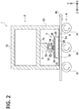
- FIG. 2 is a schematic cross-sectional view of the ultraviolet light irradiation device taken along line A-A in FIG. 1 .
- the ultraviolet light irradiation device 1 includes a housing 2 and an excimer lamp 3.
- the ultraviolet light irradiation device 1 irradiates a workpiece W1 disposed to face the light-emitting surface 3a of the excimer lamp 3 with ultraviolet light.
- the direction in which the excimer lamp 3 is extended (tube axis direction) is defined as the X direction
- the direction in which the electrodes 34, 35 of the excimer lamp 3 face each other is defined as the Y direction
- the direction orthogonal to the X direction and Y direction is defined as the Z direction, as shown in FIG. 1 .
- a positive or negative sign is added to the direction, such as "+X direction” or "-X direction”.
- the direction is simply expressed as "X direction”.
- the ultraviolet light irradiation device 1 is placed with the Y direction as a vertical direction.
- a transport mechanism 4 that transports the workpiece W1 is disposed below (the -Y side) the ultraviolet light irradiation device 1.
- the transport mechanism 4 includes a plurality of rollers 41 and drive units 42, the drive units 42 being provided at both ends of each roller 41 to drive the rollers 41.
- the workpiece W1 loaded into the transport mechanism 4 is placed on the roller 41 and is transported to a place under the excimer lamp 3 by driving the roller 41.
- the workpiece W1 that has been transported is in close proximity to the excimer lamp 3 and is irradiated with vacuum ultraviolet light from the excimer lamp 3.
- the workpiece W1 that has been irradiated with vacuum ultraviolet light is loaded out of the transport mechanism 4.
- the housing 2 has a rectangular top surface 21 and side surfaces 22 extending downward from each side of the top surface 21, and is a box shape with an opening 23 at the bottom.
- the housing 2 is made of metal, for example, an aluminum alloy.
- FIG. 3 is a cross-sectional view of an excimer lamp 3 that is cut in a plane perpendicular to the X direction.
- the excimer lamp 3 includes a light-emitting tube 30.
- the light-emitting tube 30 is made of a material that is transparent to ultraviolet light (e.g. quartz glass).
- the light-emitting tube 30 has an upper wall 31, a lower wall 32, and side walls 33, and is a rectangular tube with a flat cross section.
- the light-emitting tube 30 is a long shape in the X direction.
- the inside of the light-emitting tube 30 is filled with a discharge gas that generates excimer molecules through discharge.
- the discharge gas includes xenon (Xe).
- Xe xenon
- a more detailed example of the discharge gas includes a gas with a mixture of xenon (Xe) and neon (Ne) in a predetermined ratio, and may also contain a trace amount of oxygen or hydrogen.
- the outer surface of the upper wall 31 and the outer surface of the lower wall 32 in the light-emitting tube 30 are provided with a pair of electrodes 34, 35 facing each other.
- the electrode 34 provided on the outer surface of the upper wall 31 is a high voltage supply electrode
- the electrode 35 provided on the outer surface of the lower wall 32 is a ground electrode.
- the electrodes 34, 35 have a mesh shape, allowing light to pass through the openings in the mesh.
- the shape of the electrodes 34, 35 may be different from each other, and the electrode 34 may have a solid shape, since it does not need to allow light to pass through it.
- the electrode 35 can be any shape that allows light to pass through it, for examples, the electrode 35 having a shape with a plurality of slits.
- the electrodes 34, 35 are made of the same material, printed on the outer surface of the light-emitting tube 30 through screen printing and then formed through firing; however, they may be made of a different material and formed through a different method.
- the materials that constitute the electrodes 34, 35 can include, for example, gold, platinum, or alloys containing these materials.
- the excimer lamp 3 includes a reflective coating 36.
- the reflective coating 36 is formed on the inner surface of the upper wall 31, which is the opposite side of the light-emitting surface 3a of the light-emitting tube 30.
- the reflective coating 36 reflects the ultraviolet light that generates in the light-emitting tube 30 and travels toward the upper side, to the lower side.
- the reflective coating 36 according to the present embodiment is formed only on the inner surface of the upper wall 31, however, the reflective coating 36 may also be formed on the inner surfaces of the side walls 33.
- the material that constitutes the reflective coating 36 can be obtained, for example, by coating and firing suspension solution or the like that contains particulate silica (SiO 2 ), alumina (Al 2 O 3 ) or the like.
- the excimer lamp 3 is disposed in the housing 2.
- the excimer lamp 3 is held by a pair of lamp holders 24 below the housing 2 with a space apart from the housing 2.
- the ultraviolet light irradiation device 1 is provided with a movement limiting member 5 that prevents the excimer lamp 3 from moving upward with respect to the housing 2.
- the movement limiting member 5 is disposed between the excimer lamp 3 and the housing 2.
- the movement limiting member 5 is provided to protrude downward from the lower surface 2a of the housing 2 toward the excimer lamp 3.
- the movement limiting member 5 is provided with a cross-sectional U-shaped base 51 that is fixed to the lower surface 2a of the housing 2, and a wheel 52 that is rotatably supported by the base 51.
- the wheel 52 is rotatably attached to the opening of the base 51 with a fixing screw 53.
- the wheel 52 is rotatable along the X direction; in the case that the wheel 52 contacts the upper wall 31 of the light-emitting tube 30, the wheel 52 rotates in response to the displacement of the light-emitting tube 30 along the X direction.
- the wheel 52 is made of an insulating material such as ceramic.
- Two movement limiting members 5 are disposed at an interval in the X direction.
- Each of the movement limiting members 5 according to the present embodiment is located at approximately 25% inside the length of the excimer lamp 3 from each of both ends of the excimer lamp 3 in the X direction. Only one movement limiting member 5 may be disposed at the approximate middle of the excimer lamp 3 in the X direction. Three or more movement limiting members 5 may also be disposed.
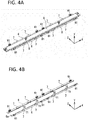
- FIG. 4A is a schematic perspective view of the excimer lamp 3 and the shielding plates 6, and FIG. 4B is a schematic perspective view of the shielding plates 6 only.
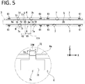
- FIG. 5 is a schematic plan view of the excimer lamp 3 and the shielding plates 6 viewed from above.
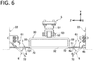
- FIG. 6 is a schematic view of the excimer lamp 3 and the shielding plates 6 viewed from the X direction.
- the shielding plates 6 are each disposed on the each side of the light-emitting tube 30 in the Z direction and extend along the X direction.
- the shielding plates 6 each protrude horizontally from the inner side wall of the side surface 22 of the housing 2 toward the light-emitting tube 30, as shown in Figure 6 .
- the shielding plate 6 is located at approximately the same height as the lower wall 32 of the light-emitting tube 30.
- the material that constitutes the shielding plate 6 is, for example, stainless steel.
- the shielding plate 6 has a thickness of 1 to 1.5 mm, for example.
- the shielding plate 6 is provided to shield cooling gas, for example, which is injected into the upper part of the light-emitting tube 30 from cooling mechanism (not shown) for cooling the light-emitting tube 30, from flowing into the light-emitting surface 3a side.
- the shielding plate 6 also serves to shield the electric field formed between the pair of electrodes 34, 35.
- the tip 6a of the shielding plate 6 is disposed in close proximity to the side wall 33 of the light-emitting tube 30.
- the term "close proximity” here refers to a separation distance of 3 mm or less.
- the ultraviolet light irradiation device 1 according to the present embodiment specifically has the separation distance of 3 mm between the shielding plate 6 and the light-emitting tube 30.
- the tip 6a of the shielding plate 6 can be disposed to be in contact with the side wall 33 of the light-emitting tube 30.
- the base end 6b of the shielding plate 6 is rotatably supported at the bottom of the side surface 22 of the housing 2.
- the base end 6b of the shielding plate 6 is fixed to the housing 2 via a hinge 61.
- Each shielding plate is provided with four hinges; one hinge is provided at each end of the shielding plate 6 in the X direction, and two hinges are provided in the middle of the shielding plate in the X direction.
- the shielding plate 6 can rotate around the hinges 61 to accommodate the following positions: A first position, which is approximately parallel to the horizontal plane (shown by the solid line in Fig. 6 ), or a second position, which is inclined approximately at 45 degrees to the horizontal plane (shown by the double-dotted chain line in Fig. 6 ).
- the tip 6a of the shielding plate 6 is close to the light-emitting tube 30 in the first position, whereas the tip 6a of the shielding plate 6 is spaced apart from the light-emitting tube 30 in the second position.
- the shielding plate 6 is set in the first position to block the cooling gas when the ultraviolet light irradiation device 1 irradiates with ultraviolet light.
- the shielding plate 6 is set in the second position to readily replace the excimer lamp 3 when the excimer lamp 3 is to be replaced.
- the ultraviolet light irradiation device 1 is provided with a plurality of fall prevention members 7 on the lower side (light-emitting surface 3a side) of the excimer lamp 3.
- the fall prevention members 7 are disposed on the shielding plate 6.
- the material constituting the fall prevention members 7 is, for example, stainless steel.
- the ultraviolet light irradiation device 1 has a total of eight fall prevention members 7, since each shielding plate 6 is provided with four fall prevention members 7.
- the shielding plate 6 is composed of a plurality of plates and the fall prevention members 7 are welded between the plates to fix them.
- the fall prevention member 7 is disposed between the movement limiting member 5 and the hinge 61 in the X direction.
- the fall prevention member 7 includes a rectangular body 71 that is fixed to the shielding plate 6, and a protruding portion 72 that protrudes in the Z direction from the body 71 toward the light-emitting tube 30.
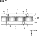
- the protruding portion 72 extends beyond the tip 6a of the shielding plate 6 to a position that overlaps with the lower wall 32 of the light-emitting tube 30 when viewed from the Y direction (vertical direction). However, the protruding portion 72 is preferably located at a position that does not overlap with the electrode 35 on the lower wall 32 of the light-emitting tube 30 when viewed from the Y direction, as shown in Figure 7 . The protruding portion 72 may or may not be in contact with the lower wall 32 of the light-emitting tube 30 in the normal operation.
- the fall prevention members 7 are arranged to surround each of the movement limiting members 5.
- the fall prevention members 7a to 7d shown in Fig. 5 ).
- the fall prevention members 7 are disposed on both sides of the X direction with respect to the movement limiting member 5, i.e., the +X side and -X side.
- the area on the +X side with respect to the movement limiting member 5 corresponds to a first area R1 according to the present invention
- the area on the -X side with respect to the movement limiting member 5 corresponds to a second area R2 according to the present invention.
- the fall prevention members 7a, 7b are disposed in the first area R1
- the fall prevention members 7c, 7d are disposed in the second area R2.
- the fall prevention members 7 are arranged such that the protruding portions 72 overlap with the light-emitting tube 30 in the first area R1 on the +X side and in the second area R2 on the -X side when viewed from the vertical direction. This configuration allows the tip of the broken light-emitting tube 30 to be held by the protruding portion 72 of the fall prevention member 7 to prevent the tip of the broken light-emitting tube 30 from falling off even if the light-emitting tube 30 breaks at the point where the movement limiting member 5 is in contact.
- the protruding portion 72 is preferably disposed at a distance 72X of 200 mm or less from the movement limiting body 5 in the X direction.
- the distance 72X refers to the shortest distance from the lower end of the wheel 52 to the protruding portion 72 in the X-direction. If the distance 72X is larger than 200 mm, the broken light-emitting tube 30 may bend downward, resulting in the tip of the tube to be in contact with the workpiece W1.
- the protruding portion 72 have a width 72W of 10 - 30 mm. If the width 72W is smaller than 10 mm, the protruding portion 72 may not hold the broken light-emitting tube 30 sufficiently. In contrast, if the width 72W is larger than 30 mm, the protruding portion 72 may block off a larger amount of ultraviolet light from the excimer lamp 3, which may adversely affect the processing of the workpiece W1.
- the protruding portion 72 have a protruding length 72L of 5 - 7 mm from the tip 6a of the shielding plate 6. If the protruding length 72L is smaller than 5 mm, the protruding portion 72 may not hold the broken light-emitting tube 30 sufficiently. In contrast, if the protruding length 72L is larger than 7 mm, the protruding portion 72 may block off a larger amount of ultraviolet light from the excimer lamp 3, which may adversely affect the processing of the workpiece W1.
- the protruding portion 72 have a thickness 72T of 1.5 mm or less. If the thickness 72T is larger than 1.5 mm, the excimer lamp 3 needs to be more distant from the workpiece W1 to prevent the protruding portion 72 from being in contact with the workpiece W1. This configuration may cause difficulty in efficiently irradiating the workpiece W1 with ultraviolet light.
- the fall prevention members 7 be arranged such that the protruding portions 72 are displaced in the X direction from each other, as shown in Figure 5 . Since the workpiece W1 is irradiated with ultraviolet light while being transported in the Z direction orthogonal to the X direction, if the areas shielded by the protruding portions 72 overlap in the X direction, it may adversely affect the processing of the workpiece W1. Hence, it is preferable that the protruding portions 72 be arranged in a manner that they do not overlap in the X direction. Arranging the protruding portions 72 in a staggered position in the X direction enables the tip of the broken light-emitting tube 30 to be held securely according to the broken position of the light-emitting tube 30.
- each protruding portion 72 of the fall prevention member 7 independently overlaps with the light-emitting tube 30 in the first region R1 and the second region R2 when viewed from the Y direction; however, the arrangement of the protruding portion 72 is not limited to that of the embodiments.
- the protruding portion 72 of the fall prevention member 7 may overlap with the light-emitting tube 30 continuously in the first region R1 and the second region R2 in a manner of straddling the movement limiting member 5.
- the protruding portion 72 of the fall prevention member 7 may extend from the movement limiting member 5 to the +X direction and -X direction.
- the protruding portion 72 may extend over the entire excimer lamp 3 in the X direction.
- the fall prevention members 7 are provided on the +Z side and -Z side of the excimer lamp 3; however, the arrangement of the fall prevention members 7 is not limited to that of the embodiments.
- the fall prevention members 7 may be, for example, provided only on the +Z side of the excimer lamp 3, as shown in Figs. 8B and 8C .
- two fall prevention members 7 are provided in each of the first region R1 and the second region R2; however, the arrangement of the prevention members 7 is not limited to that of the embodiments. At least one fall prevention member 7 can be provided in each of the first region R1 and second region R2, for example, as shown in Figure 8D .
- the shielding plate 6 and the fall prevention member 7 are separate components; however, the configuration is not limited to these separate components.
- the shielding plate 6 and the fall prevention member 7 can be integrated into a single component.
Landscapes
- Physics & Mathematics (AREA)
- Electromagnetism (AREA)
- Engineering & Computer Science (AREA)
- Plasma & Fusion (AREA)
- Optics & Photonics (AREA)
- Cleaning In General (AREA)
- Cleaning Or Drying Semiconductors (AREA)
- Physical Or Chemical Processes And Apparatus (AREA)
- Vessels And Coating Films For Discharge Lamps (AREA)
Abstract
Description
- The present invention relates to an ultraviolet light irradiation device.
- Ultraviolet light irradiation devices using excimer lamps as a light source have been known to irradiate with vacuum ultraviolet light for cleaning substrates in the manufacturing process of semiconductor substrates and liquid crystal substrates.
- An excimer lamp used in the ultraviolet light irradiation device, which is filled with xenon gas in a light-emitting tube made of quartz glass, emits ultraviolet light of 172 nm.
- The excimer lamp has a rectangular cross-sectional shape of the light-emitting tube, includes a pair of electrodes on the opposite outer surfaces and an ultraviolet light reflective coating on the one inner surface, and emits ultraviolet light from the other surface. The excimer lamp is supported by a lamp holder at both ends of the lamp in the tube axial direction inside a housing, and the central part of the lamp is supported by a support that holds the lower surface of the light-emitting tube. (Refer to Patent Literature 1)
- In the excimer lamp, the light-emitting tube undergoes a curve to the opposite side of the light-emitting surface (the side where an ultraviolet light reflective coating is formed) when the lamp lighting time elapses. The reason for the curve is explained on the following. Ultraviolet light distortion accumulates on the light-emitting surface of the light-emitting tube with the elapse of the lamp lighting time. However, the inner surfaces of the light-emitting tube except the light-emitting surface are covered with ultraviolet light reflective coating, hence the ultraviolet light distortion is less likely to accumulate on the inner surfaces of the light-emitting tube. Consequently, the light-emitting tube on the side of the light-emitting surface contracts mainly in the longitudinal direction (tube axial direction), resulting in curving convexly toward the direction where the ultraviolet light reflective coating is formed.
- A technique is known to prevent this curve by providing a movement limiting member having a wheel in a housing of the ultraviolet light irradiation device to mechanically restrain the curve of the light-emitting tube. (Refer to Patent Literature 2)
-
- Patent Literature 1: Japanese Patent Application Laid-Open Publication No.
2011-139988 - Patent Literature 2: Japanese Patent Application Laid-Open Publication No.
2010-80351 - With the elapse of the lamp lighting time, however, the light-emitting tube has been pressed hard against the movement limiting member in an attempt to curve further, and finally starts to break at a contact point where the light-emitting tube is in contact with the movement limiting member.
- A support is provided near the center of the light-emitting tube to support the light-emitting tube from below, but the position of the support is not specifically considered. In the event that the light-emitting tube breaks, both ends of the excimer lamp are held in the housing; however, depending on the location of the break, the tip of the broken light-emitting tube may fall off to the underside of the device, damaging a workpiece or a roller, which is a transport mechanism.
- In view of the above issue, the object of the present invention is to provide an ultraviolet light irradiation device that prevents an excimer lamp from falling off even if the light-emitting tube of the excimer lamp breaks, and to provide an ultraviolet light irradiation device that does not damage a workpiece or a roller, which is a transport mechanism located at the underside of the device.
- An ultraviolet light irradiation device according to the present invention includes an excimer lamp provided with a long light-emitting tube transparent to ultraviolet light, a pair of electrodes disposed on the outer wall surface of the light-emitting tube to face each other in the vertical direction, and a reflective coating formed on the upper inner surface of the light-emitting tube; a housing that is disposed on the upper side of the excimer lamp and holds both ends of the excimer lamp in the longitudinal direction; a movement limiting member that protrudes from the bottom surface of the housing toward the excimer lamp; and a fall prevention member disposed under the excimer lamp. At least a part of the fall prevention member overlaps with the light-emitting tube in a first region and a second region that are located on both sides of the excimer lamp in the longitudinal direction with respect to the movement limiting member when viewed from the vertical direction.
- Even if the light-emitting tube breaks at a point where the movement limiting member is in contact, this configuration allows a tip of the broken light-emitting tube to be held by the fall prevention member, prevents the excimer lamp from falling down, and therefore avoids damaging a workpiece or a roller, which is a transport mechanism located at the underside of the device.
- At least a part of the fall prevention member may overlap with the light-emitting tube independently in the first region and the second region. At least a part of the fall prevention member may overlap with the light-emitting tube continuously in the first region and the second region in a manner of straddling the movement limiting member.
- These configurations, which allow the fall prevention member to be disposed to overlap at least partially with the light-emitting tube in the first region and the second region that are located on both sides of the excimer lamp in the longitudinal direction with respect to the movement limiting member, prevent the excimer lamp from falling down, even if the light-emitting tube breaks.
- It is preferable that the fall prevention member do not overlap with the electrode provided on the lower outer wall surface of the light-emitting tube when viewed from the vertical direction.
- This configuration reduces the amount of light blocked by the fall prevention member.
- The ultraviolet light irradiation device may include a shielding plate protruding from the inner side wall of the housing toward the light-emitting tube and being disposed such that the tip of the shielding plate is in close proximity to the light-emitting tube. In this configuration, the fall prevention member may protrude further from the tip of the shielding plate toward the light-emitting tube.
- This configuration, which allows the fall prevention member to protrude further from the tip of the shielding plate toward the light-emitting tube, enables the distance between the fall prevention member and the light-emitting tube to be closer, thus readily ensuring the strength of the fall prevention member.
- The base end of the shielding plate is preferably supported by the housing to allow the tip of the shielding plate to be rotatable in a direction away from the light-emitting tube.
- This configuration allows an excimer lamp to be readily replaced, when necessary, by rotating the shielding plate in a manner of separating the tip of the shielding plate from the light-emitting tube, since the shielding plate and the fall prevention member move away from the light-emitting tube.
-
-
FIG. 1 is a schematic elevation view illustrating a configuration of an ultraviolet light irradiation device according to an embodiment of the present invention. -
FIG. 2 is a schematic cross-sectional view of the ultraviolet light irradiation device taken along line A-A inFIG. 1 . -
FIG. 3 is a schematic cross-sectional view of an excimer lamp. -
FIG. 4A is a schematic perspective view of the excimer lamp and a shielding plate. -
FIG. 4B is a schematic perspective view of the shielding plate. -
FIG. 5 is a schematic plan view of the excimer lamp and the shielding plate. -
FIG. 6 is a schematic view of the excimer lamp and the shielding plate viewed from the tube axial direction of the excimer lamp. -
FIG. 7 is a schematic view of the excimer lamp and the shielding plate viewed from below. -
FIG. 8A is a schematic plan view of the excimer lamp and the shielding plate according to another embodiment of the present invention. -
FIG. 8B is a schematic plan view of the excimer lamp and the shielding plate according to another embodiment of the present invention. -
FIG. 8C is a schematic plan view of the excimer lamp and the shielding plate according to another embodiment of the present invention. -
FIG. 8D is a schematic plan view of the excimer lamp and the shielding plate according to another embodiment of the present invention. - Embodiments of an ultraviolet light irradiation device according to the present invention are described with reference to the drawings. Since each drawing is illustrated schematically, it is noted that the dimensional ratios in each drawing do not necessarily match the actual dimensional ratios, and the dimension ratios do not necessarily match between each drawing.
-
FIG. 1 is a schematic elevation view illustrating a configuration of an ultraviolet light irradiation device according to an embodiment of the present invention.FIG. 2 is a schematic cross-sectional view of the ultraviolet light irradiation device taken along line A-A inFIG. 1 . As shown inFIG. 1 , the ultraviolet light irradiation device 1 includes ahousing 2 and anexcimer lamp 3. The ultraviolet light irradiation device 1 irradiates a workpiece W1 disposed to face the light-emittingsurface 3a of theexcimer lamp 3 with ultraviolet light. - In the following descriptions, the direction in which the
excimer lamp 3 is extended (tube axis direction) is defined as the X direction, the direction in which theelectrodes excimer lamp 3 face each other is defined as the Y direction, and the direction orthogonal to the X direction and Y direction is defined as the Z direction, as shown inFIG. 1 . In the case of describing a direction to distinguish a positive direction from a negative direction, a positive or negative sign is added to the direction, such as "+X direction" or "-X direction". In the case of describing a direction without distinguishing a positive direction from a negative direction, the direction is simply expressed as "X direction". The ultraviolet light irradiation device 1 is placed with the Y direction as a vertical direction. - A
transport mechanism 4 that transports the workpiece W1 is disposed below (the -Y side) the ultraviolet light irradiation device 1. Thetransport mechanism 4 includes a plurality ofrollers 41 and driveunits 42, thedrive units 42 being provided at both ends of eachroller 41 to drive therollers 41. The workpiece W1 loaded into thetransport mechanism 4 is placed on theroller 41 and is transported to a place under theexcimer lamp 3 by driving theroller 41. The workpiece W1 that has been transported, is in close proximity to theexcimer lamp 3 and is irradiated with vacuum ultraviolet light from theexcimer lamp 3. The workpiece W1 that has been irradiated with vacuum ultraviolet light, is loaded out of thetransport mechanism 4. - The
housing 2 has a rectangulartop surface 21 and side surfaces 22 extending downward from each side of thetop surface 21, and is a box shape with anopening 23 at the bottom. Thehousing 2 is made of metal, for example, an aluminum alloy. -
FIG. 3 is a cross-sectional view of anexcimer lamp 3 that is cut in a plane perpendicular to the X direction. Theexcimer lamp 3 includes a light-emittingtube 30. The light-emittingtube 30 is made of a material that is transparent to ultraviolet light (e.g. quartz glass). The light-emittingtube 30 has anupper wall 31, alower wall 32, andside walls 33, and is a rectangular tube with a flat cross section. The light-emittingtube 30 is a long shape in the X direction. - The inside of the light-emitting
tube 30 is filled with a discharge gas that generates excimer molecules through discharge. In the present embodiment, the discharge gas includes xenon (Xe). A more detailed example of the discharge gas includes a gas with a mixture of xenon (Xe) and neon (Ne) in a predetermined ratio, and may also contain a trace amount of oxygen or hydrogen. - The outer surface of the
upper wall 31 and the outer surface of thelower wall 32 in the light-emittingtube 30 are provided with a pair ofelectrodes electrode 34 provided on the outer surface of theupper wall 31 is a high voltage supply electrode, and theelectrode 35 provided on the outer surface of thelower wall 32 is a ground electrode. Theelectrodes - The shape of the
electrodes electrode 34 may have a solid shape, since it does not need to allow light to pass through it. Theelectrode 35 can be any shape that allows light to pass through it, for examples, theelectrode 35 having a shape with a plurality of slits. - The
electrodes tube 30 through screen printing and then formed through firing; however, they may be made of a different material and formed through a different method. The materials that constitute theelectrodes - The
excimer lamp 3 includes areflective coating 36. Thereflective coating 36 is formed on the inner surface of theupper wall 31, which is the opposite side of the light-emittingsurface 3a of the light-emittingtube 30. Thereflective coating 36 reflects the ultraviolet light that generates in the light-emittingtube 30 and travels toward the upper side, to the lower side. Thereflective coating 36 according to the present embodiment is formed only on the inner surface of theupper wall 31, however, thereflective coating 36 may also be formed on the inner surfaces of theside walls 33. - The material that constitutes the
reflective coating 36 can be obtained, for example, by coating and firing suspension solution or the like that contains particulate silica (SiO2), alumina (Al2O3) or the like. - The
excimer lamp 3 is disposed in thehousing 2. Theexcimer lamp 3 is held by a pair oflamp holders 24 below thehousing 2 with a space apart from thehousing 2. - In the light-emitting
tube 30 according to the present embodiment, distortion caused by the ultraviolet light accumulates in thelower wall 32 on the light-emittingsurface 3a with the elapse of the lamp lighting time, whereas the distortion caused by the ultraviolet light is less likely to accumulate in theupper wall 31 where thereflective coating 36 is formed, hence thelower wall 32 contracts mainly in the X direction, resulting in a convex curve upward (+Y side) as the whole light-emitting tube. For this reason, the ultraviolet light irradiation device 1 is provided with amovement limiting member 5 that prevents theexcimer lamp 3 from moving upward with respect to thehousing 2. - The
movement limiting member 5 is disposed between theexcimer lamp 3 and thehousing 2. Themovement limiting member 5 is provided to protrude downward from thelower surface 2a of thehousing 2 toward theexcimer lamp 3. Themovement limiting member 5 is provided with a cross-sectionalU-shaped base 51 that is fixed to thelower surface 2a of thehousing 2, and awheel 52 that is rotatably supported by thebase 51. Thewheel 52 is rotatably attached to the opening of the base 51 with a fixingscrew 53. Thewheel 52 is rotatable along the X direction; in the case that thewheel 52 contacts theupper wall 31 of the light-emittingtube 30, thewheel 52 rotates in response to the displacement of the light-emittingtube 30 along the X direction. Thewheel 52 is made of an insulating material such as ceramic. - Two
movement limiting members 5 are disposed at an interval in the X direction. Each of themovement limiting members 5 according to the present embodiment is located at approximately 25% inside the length of theexcimer lamp 3 from each of both ends of theexcimer lamp 3 in the X direction. Only onemovement limiting member 5 may be disposed at the approximate middle of theexcimer lamp 3 in the X direction. Three or moremovement limiting members 5 may also be disposed. - The ultraviolet light irradiation device 1 is provided with a pair of shielding
plates 6.FIG. 4A is a schematic perspective view of theexcimer lamp 3 and theshielding plates 6, andFIG. 4B is a schematic perspective view of theshielding plates 6 only.FIG. 5 is a schematic plan view of theexcimer lamp 3 and theshielding plates 6 viewed from above.FIG. 6 is a schematic view of theexcimer lamp 3 and theshielding plates 6 viewed from the X direction. - The
shielding plates 6 are each disposed on the each side of the light-emittingtube 30 in the Z direction and extend along the X direction. Theshielding plates 6 each protrude horizontally from the inner side wall of theside surface 22 of thehousing 2 toward the light-emittingtube 30, as shown inFigure 6 . The shieldingplate 6 is located at approximately the same height as thelower wall 32 of the light-emittingtube 30. The material that constitutes the shieldingplate 6 is, for example, stainless steel. The shieldingplate 6 has a thickness of 1 to 1.5 mm, for example. - The shielding
plate 6 is provided to shield cooling gas, for example, which is injected into the upper part of the light-emittingtube 30 from cooling mechanism (not shown) for cooling the light-emittingtube 30, from flowing into the light-emittingsurface 3a side. The shieldingplate 6 also serves to shield the electric field formed between the pair ofelectrodes tip 6a of theshielding plate 6 is disposed in close proximity to theside wall 33 of the light-emittingtube 30. The term "close proximity" here refers to a separation distance of 3 mm or less. The ultraviolet light irradiation device 1 according to the present embodiment specifically has the separation distance of 3 mm between the shieldingplate 6 and the light-emittingtube 30. Thetip 6a of theshielding plate 6 can be disposed to be in contact with theside wall 33 of the light-emittingtube 30. - The
base end 6b of theshielding plate 6 is rotatably supported at the bottom of theside surface 22 of thehousing 2. Thebase end 6b of theshielding plate 6 is fixed to thehousing 2 via ahinge 61. Each shielding plate is provided with four hinges; one hinge is provided at each end of theshielding plate 6 in the X direction, and two hinges are provided in the middle of the shielding plate in the X direction. - The shielding
plate 6 can rotate around thehinges 61 to accommodate the following positions: A first position, which is approximately parallel to the horizontal plane (shown by the solid line inFig. 6 ), or a second position, which is inclined approximately at 45 degrees to the horizontal plane (shown by the double-dotted chain line inFig. 6 ). Thetip 6a of theshielding plate 6 is close to the light-emittingtube 30 in the first position, whereas thetip 6a of theshielding plate 6 is spaced apart from the light-emittingtube 30 in the second position. The shieldingplate 6 is set in the first position to block the cooling gas when the ultraviolet light irradiation device 1 irradiates with ultraviolet light. In contrast, the shieldingplate 6 is set in the second position to readily replace theexcimer lamp 3 when theexcimer lamp 3 is to be replaced. - The ultraviolet light irradiation device 1 is provided with a plurality of
fall prevention members 7 on the lower side (light-emittingsurface 3a side) of theexcimer lamp 3. Thefall prevention members 7 are disposed on theshielding plate 6. The material constituting thefall prevention members 7 is, for example, stainless steel. - The ultraviolet light irradiation device 1 according to the present embodiment has a total of eight
fall prevention members 7, since each shieldingplate 6 is provided with fourfall prevention members 7. In the present embodiment, the shieldingplate 6 is composed of a plurality of plates and thefall prevention members 7 are welded between the plates to fix them. - The
fall prevention member 7 is disposed between themovement limiting member 5 and thehinge 61 in the X direction. Thefall prevention member 7 includes arectangular body 71 that is fixed to theshielding plate 6, and a protrudingportion 72 that protrudes in the Z direction from thebody 71 toward the light-emittingtube 30. - The protruding
portion 72 extends beyond thetip 6a of theshielding plate 6 to a position that overlaps with thelower wall 32 of the light-emittingtube 30 when viewed from the Y direction (vertical direction). However, the protrudingportion 72 is preferably located at a position that does not overlap with theelectrode 35 on thelower wall 32 of the light-emittingtube 30 when viewed from the Y direction, as shown inFigure 7 . The protrudingportion 72 may or may not be in contact with thelower wall 32 of the light-emittingtube 30 in the normal operation. - Four
fall prevention members 7 are arranged to surround each of themovement limiting members 5. Hereinafter, in case of distinguishing the fourfall prevention members 7 that surround themovement limiting member 5, they will be referred to as thefall prevention members 7a to 7d (shown inFig. 5 ). Thefall prevention members 7 are disposed on both sides of the X direction with respect to themovement limiting member 5, i.e., the +X side and -X side. The area on the +X side with respect to themovement limiting member 5 corresponds to a first area R1 according to the present invention, and the area on the -X side with respect to themovement limiting member 5 corresponds to a second area R2 according to the present invention. In the present embodiment, thefall prevention members fall prevention members fall prevention members 7 are arranged such that the protrudingportions 72 overlap with the light-emittingtube 30 in the first area R1 on the +X side and in the second area R2 on the -X side when viewed from the vertical direction. This configuration allows the tip of the broken light-emittingtube 30 to be held by the protrudingportion 72 of thefall prevention member 7 to prevent the tip of the broken light-emittingtube 30 from falling off even if the light-emittingtube 30 breaks at the point where themovement limiting member 5 is in contact. - The protruding
portion 72 is preferably disposed at adistance 72X of 200 mm or less from themovement limiting body 5 in the X direction. Thedistance 72X refers to the shortest distance from the lower end of thewheel 52 to the protrudingportion 72 in the X-direction. If thedistance 72X is larger than 200 mm, the broken light-emittingtube 30 may bend downward, resulting in the tip of the tube to be in contact with the workpiece W1. - It is preferable that the protruding
portion 72 have awidth 72W of 10 - 30 mm. If thewidth 72W is smaller than 10 mm, the protrudingportion 72 may not hold the broken light-emittingtube 30 sufficiently. In contrast, if thewidth 72W is larger than 30 mm, the protrudingportion 72 may block off a larger amount of ultraviolet light from theexcimer lamp 3, which may adversely affect the processing of the workpiece W1. - It is preferable that the protruding
portion 72 have aprotruding length 72L of 5 - 7 mm from thetip 6a of theshielding plate 6. If the protrudinglength 72L is smaller than 5 mm, the protrudingportion 72 may not hold the broken light-emittingtube 30 sufficiently. In contrast, if theprotruding length 72L is larger than 7 mm, the protrudingportion 72 may block off a larger amount of ultraviolet light from theexcimer lamp 3, which may adversely affect the processing of the workpiece W1. - It is preferable that the protruding
portion 72 have athickness 72T of 1.5 mm or less. If thethickness 72T is larger than 1.5 mm, theexcimer lamp 3 needs to be more distant from the workpiece W1 to prevent the protrudingportion 72 from being in contact with the workpiece W1. This configuration may cause difficulty in efficiently irradiating the workpiece W1 with ultraviolet light. - It is preferable that the
fall prevention members 7 be arranged such that the protrudingportions 72 are displaced in the X direction from each other, as shown inFigure 5 . Since the workpiece W1 is irradiated with ultraviolet light while being transported in the Z direction orthogonal to the X direction, if the areas shielded by the protrudingportions 72 overlap in the X direction, it may adversely affect the processing of the workpiece W1. Hence, it is preferable that the protrudingportions 72 be arranged in a manner that they do not overlap in the X direction. Arranging the protrudingportions 72 in a staggered position in the X direction enables the tip of the broken light-emittingtube 30 to be held securely according to the broken position of the light-emittingtube 30. - The embodiments of the present invention have been described above in accordance with the drawings, but it should be noted that the specific configuration is not limited to these embodiments. The scope of the present invention is presented by the claims in addition to the description of embodiments above, and further includes all modifications within the scope of the claims.
- The configurations adopted in each of the embodiments described above can be adopted to those of any other embodiments. The specific configuration of each member is not limited to the embodiment described above, but can be modified in various ways without departing from the gist of the present invention.
- In the ultraviolet light irradiation device 1 of the above embodiments, each protruding
portion 72 of thefall prevention member 7 independently overlaps with the light-emittingtube 30 in the first region R1 and the second region R2 when viewed from the Y direction; however, the arrangement of the protrudingportion 72 is not limited to that of the embodiments. The protrudingportion 72 of thefall prevention member 7 may overlap with the light-emittingtube 30 continuously in the first region R1 and the second region R2 in a manner of straddling themovement limiting member 5. Specifically, as shown inFigure 8A , the protrudingportion 72 of thefall prevention member 7 may extend from themovement limiting member 5 to the +X direction and -X direction. In addition, the protrudingportion 72 may extend over theentire excimer lamp 3 in the X direction. - In the ultraviolet light irradiation device 1 of the above embodiments, the
fall prevention members 7 are provided on the +Z side and -Z side of theexcimer lamp 3; however, the arrangement of thefall prevention members 7 is not limited to that of the embodiments. Thefall prevention members 7 may be, for example, provided only on the +Z side of theexcimer lamp 3, as shown inFigs. 8B and8C . - In the ultraviolet light irradiation device 1 of the above embodiments, two
fall prevention members 7 are provided in each of the first region R1 and the second region R2; however, the arrangement of theprevention members 7 is not limited to that of the embodiments. At least onefall prevention member 7 can be provided in each of the first region R1 and second region R2, for example, as shown inFigure 8D . - In the ultraviolet light irradiation device 1 of the above embodiments, the shielding
plate 6 and thefall prevention member 7 are separate components; however, the configuration is not limited to these separate components. The shieldingplate 6 and thefall prevention member 7 can be integrated into a single component. -
- 1
- ultraviolet light irradiation device
- 2
- housing
- 2a
- lower surface of housing
- 3
- excimer lamp
- 3a
- light-emitting surface
- 5
- movement limiting member
- 6
- shielding plate
- 6a
- tip
- 6b
- base end
- 7
- fall prevention member
- 7a
- fall prevention member
- 7b
- fall prevention member
- 7c
- fall prevention member
- 7d
- fall prevention member
- 30
- light-emitting tube
- 31
- upper wall
- 32
- lower wall
- 33
- side wall
- 34
- electrode
- 35
- electrode
- 36
- reflective coating
- 52
- wheel
- 61
- hinge
- 71
- body
- 72
- protruding portion
- W1
- workpiece
Claims (6)
- An ultraviolet light irradiation device (1) comprising:an excimer lamp (3) includinga long light-emitting tube (30) transparent to ultraviolet light,a pair of electrodes (34, 35) disposed on the outer wall surface of the light-emitting tube (30) to face each other in a vertical direction, anda reflective coating (36) formed on the upper inner wall surface of the light-emitting tube (30);a housing (2) being disposed on the upper side of the excimer lamp (3), the housing (2) for holding both ends of the excimer lamp (3) in a longitudinal direction;a movement limiting member (5) protruding from the bottom surface of the housing (2) toward the excimer lamp (3); anda fall prevention member (7) being disposed under the excimer lamp (3),wherein at least a part of the fall prevention member (7) overlaps with the light-emitting tube (30) in a first region and a second region, the first region and the second region being located on both sides of the excimer lamp (3) in the longitudinal direction with respect to the movement limiting member (5) when viewed from the vertical direction.
- The ultraviolet light irradiation device (1) according to claim 1, wherein at least part of each fall prevention member (7) independently overlaps with the light-emitting tube (30) in the first region and the second region.
- The ultraviolet light irradiation device (1) according to claim 1, wherein at least part of the fall prevention member (7) overlaps with the light-emitting tube (30) continuously in the first region and the second region in a manner of straddling the movement limiting member (5) .
- The ultraviolet light irradiation device (1) according to any one of claims 1 to 3, wherein the fall prevention member (7) does not overlap with the electrode (35) provided on the lower outer wall of the light-emitting tube (30) when viewed from the vertical direction.
- The ultraviolet light irradiation device (1) according to any one of claims 1 to 4, further comprising a shielding plate (6) protruding from the inner side wall of the housing (2) toward the light-emitting tube (30), the shielding plate (6) having a tip (6a) thereof, the tip (6a) being in close proximity to the light-emitting tube (30), wherein the fall prevention member (7) protrudes further from the tip (6a) of the shielding plate (6) toward the light-emitting tube (30).
- The ultraviolet light irradiation device (1) according to claim 5, wherein a base end (6b) of the shielding plate (6) is supported by the housing (2) to allow the tip (6a) of the shielding plate (6) to be rotatable in a direction away from the light-emitting tube (30).
Applications Claiming Priority (1)
| Application Number | Priority Date | Filing Date | Title |
|---|---|---|---|
| JP2020046295A JP2021150057A (en) | 2020-03-17 | 2020-03-17 | Ultraviolet emitting device |
Publications (1)
| Publication Number | Publication Date |
|---|---|
| EP3882952A1 true EP3882952A1 (en) | 2021-09-22 |
Family
ID=74673014
Family Applications (1)
| Application Number | Title | Priority Date | Filing Date |
|---|---|---|---|
| EP21158175.6A Withdrawn EP3882952A1 (en) | 2020-03-17 | 2021-02-19 | Ultraviolet light irradiation device |
Country Status (3)
| Country | Link |
|---|---|
| EP (1) | EP3882952A1 (en) |
| JP (1) | JP2021150057A (en) |
| CN (1) | CN113410122B (en) |
Cited By (1)
| Publication number | Priority date | Publication date | Assignee | Title |
|---|---|---|---|---|
| WO2025080897A1 (en) * | 2023-10-10 | 2025-04-17 | Feng Ling | Excimer lamp with integrated heat sink |
Citations (4)
| Publication number | Priority date | Publication date | Assignee | Title |
|---|---|---|---|---|
| JP2010080351A (en) | 2008-09-27 | 2010-04-08 | Ushio Inc | Excimer lamp apparatus |
| JP2011139988A (en) | 2010-01-07 | 2011-07-21 | Ushio Inc | Lamp unit |
| JP2012128962A (en) * | 2010-12-13 | 2012-07-05 | Ushio Inc | Excimer lamp, and excimer light irradiating device |
| JP2016004711A (en) * | 2014-06-18 | 2016-01-12 | ウシオ電機株式会社 | Excimer light irradiation device |
Family Cites Families (1)
| Publication number | Priority date | Publication date | Assignee | Title |
|---|---|---|---|---|
| JPH05159742A (en) * | 1991-12-09 | 1993-06-25 | A Sutoleck Donald | Shield for fluorescent tube of lighting device |
-
2020
- 2020-03-17 JP JP2020046295A patent/JP2021150057A/en active Pending
-
2021
- 2021-02-19 EP EP21158175.6A patent/EP3882952A1/en not_active Withdrawn
- 2021-03-15 CN CN202110316710.5A patent/CN113410122B/en active Active
Patent Citations (4)
| Publication number | Priority date | Publication date | Assignee | Title |
|---|---|---|---|---|
| JP2010080351A (en) | 2008-09-27 | 2010-04-08 | Ushio Inc | Excimer lamp apparatus |
| JP2011139988A (en) | 2010-01-07 | 2011-07-21 | Ushio Inc | Lamp unit |
| JP2012128962A (en) * | 2010-12-13 | 2012-07-05 | Ushio Inc | Excimer lamp, and excimer light irradiating device |
| JP2016004711A (en) * | 2014-06-18 | 2016-01-12 | ウシオ電機株式会社 | Excimer light irradiation device |
Cited By (1)
| Publication number | Priority date | Publication date | Assignee | Title |
|---|---|---|---|---|
| WO2025080897A1 (en) * | 2023-10-10 | 2025-04-17 | Feng Ling | Excimer lamp with integrated heat sink |
Also Published As
| Publication number | Publication date |
|---|---|
| CN113410122A (en) | 2021-09-17 |
| CN113410122B (en) | 2026-01-13 |
| JP2021150057A (en) | 2021-09-27 |
Similar Documents
| Publication | Publication Date | Title |
|---|---|---|
| JP5083184B2 (en) | Excimer lamp device | |
| JP2009212429A (en) | Ultraviolet radiation unit and ultraviolet radiation processing device | |
| JPWO2011024853A1 (en) | Deposition equipment | |
| US20160221049A1 (en) | Light projection device | |
| JP5682910B2 (en) | Substrate holder and substrate transfer device | |
| CN102822941A (en) | Dielectric barrier discharge lamp and lamp unit | |
| CN113410122B (en) | Ultraviolet irradiation device | |
| JP2007095327A (en) | Short arc discharge lamp | |
| JP4952394B2 (en) | Excimer light irradiation equipment | |
| CN103828017B (en) | Light-emitting device | |
| JP7549294B2 (en) | Excimer Lamp | |
| CN111394691A (en) | Mask plate, mask assembly and manufacturing method of mask assembly | |
| KR100849801B1 (en) | Excimer lamp unit | |
| TWI416584B (en) | Ultraviolet radiation treatment device | |
| CN101225505B (en) | Substrate holding table, film forming method and film forming apparatus using the same | |
| JP2009529212A (en) | Illumination system comprising a flat lamp and a frame with a foldable part | |
| JP4273028B2 (en) | Discharge lamp device | |
| US7569983B2 (en) | Flat fluorescent lamp and liquid crystal display using the same | |
| JP5504896B2 (en) | Lamp unit | |
| KR20060071313A (en) | LCD panel inspection device | |
| JP5884398B2 (en) | UV irradiation equipment | |
| TWI412042B (en) | Ultraviolet radiation device | |
| JP4337552B2 (en) | Heating unit | |
| CN101629708B (en) | Excimer lamp apparatus | |
| JP2010238475A (en) | Excimer lamp device |
Legal Events
| Date | Code | Title | Description |
|---|---|---|---|
| PUAI | Public reference made under article 153(3) epc to a published international application that has entered the european phase |
Free format text: ORIGINAL CODE: 0009012 |
|
| STAA | Information on the status of an ep patent application or granted ep patent |
Free format text: STATUS: THE APPLICATION HAS BEEN PUBLISHED |
|
| AK | Designated contracting states |
Kind code of ref document: A1 Designated state(s): AL AT BE BG CH CY CZ DE DK EE ES FI FR GB GR HR HU IE IS IT LI LT LU LV MC MK MT NL NO PL PT RO RS SE SI SK SM TR |
|
| STAA | Information on the status of an ep patent application or granted ep patent |
Free format text: STATUS: REQUEST FOR EXAMINATION WAS MADE |
|
| 17P | Request for examination filed |
Effective date: 20220311 |
|
| RBV | Designated contracting states (corrected) |
Designated state(s): AL AT BE BG CH CY CZ DE DK EE ES FI FR GB GR HR HU IE IS IT LI LT LU LV MC MK MT NL NO PL PT RO RS SE SI SK SM TR |
|
| STAA | Information on the status of an ep patent application or granted ep patent |
Free format text: STATUS: THE APPLICATION HAS BEEN WITHDRAWN |
|
| 18W | Application withdrawn |
Effective date: 20260416 |