EP3882737A1 - Fluid pressure control apparatus - Google Patents
Fluid pressure control apparatus Download PDFInfo
- Publication number
- EP3882737A1 EP3882737A1 EP20164731.0A EP20164731A EP3882737A1 EP 3882737 A1 EP3882737 A1 EP 3882737A1 EP 20164731 A EP20164731 A EP 20164731A EP 3882737 A1 EP3882737 A1 EP 3882737A1
- Authority
- EP
- European Patent Office
- Prior art keywords
- enclosure
- fluid
- control apparatus
- pressure control
- fluid pressure
- Prior art date
- Legal status (The legal status is an assumption and is not a legal conclusion. Google has not performed a legal analysis and makes no representation as to the accuracy of the status listed.)
- Granted
Links
Images

Classifications
-
- G—PHYSICS
- G05—CONTROLLING; REGULATING
- G05D—SYSTEMS FOR CONTROLLING OR REGULATING NON-ELECTRIC VARIABLES
- G05D16/00—Control of fluid pressure
- G05D16/20—Control of fluid pressure characterised by the use of electric means
- G05D16/2006—Control of fluid pressure characterised by the use of electric means with direct action of electric energy on controlling means
- G05D16/2013—Control of fluid pressure characterised by the use of electric means with direct action of electric energy on controlling means using throttling means as controlling means
- G05D16/2022—Control of fluid pressure characterised by the use of electric means with direct action of electric energy on controlling means using throttling means as controlling means actuated by a proportional solenoid
-
- F—MECHANICAL ENGINEERING; LIGHTING; HEATING; WEAPONS; BLASTING
- F17—STORING OR DISTRIBUTING GASES OR LIQUIDS
- F17D—PIPE-LINE SYSTEMS; PIPE-LINES
- F17D3/00—Arrangements for supervising or controlling working operations
- F17D3/01—Arrangements for supervising or controlling working operations for controlling, signalling, or supervising the conveyance of a product
-
- F—MECHANICAL ENGINEERING; LIGHTING; HEATING; WEAPONS; BLASTING
- F16—ENGINEERING ELEMENTS AND UNITS; GENERAL MEASURES FOR PRODUCING AND MAINTAINING EFFECTIVE FUNCTIONING OF MACHINES OR INSTALLATIONS; THERMAL INSULATION IN GENERAL
- F16K—VALVES; TAPS; COCKS; ACTUATING-FLOATS; DEVICES FOR VENTING OR AERATING
- F16K27/00—Construction of housing; Use of materials therefor
- F16K27/12—Covers for housings
-
- F—MECHANICAL ENGINEERING; LIGHTING; HEATING; WEAPONS; BLASTING
- F17—STORING OR DISTRIBUTING GASES OR LIQUIDS
- F17D—PIPE-LINE SYSTEMS; PIPE-LINES
- F17D1/00—Pipe-line systems
- F17D1/02—Pipe-line systems for gases or vapours
-
- G—PHYSICS
- G01—MEASURING; TESTING
- G01L—MEASURING FORCE, STRESS, TORQUE, WORK, MECHANICAL POWER, MECHANICAL EFFICIENCY, OR FLUID PRESSURE
- G01L19/00—Details of, or accessories for, apparatus for measuring steady or quasi-steady pressure of a fluent medium insofar as such details or accessories are not special to particular types of pressure gauges
- G01L19/0061—Electrical connection means
- G01L19/0084—Electrical connection means to the outside of the housing
-
- G—PHYSICS
- G05—CONTROLLING; REGULATING
- G05D—SYSTEMS FOR CONTROLLING OR REGULATING NON-ELECTRIC VARIABLES
- G05D16/00—Control of fluid pressure
- G05D16/20—Control of fluid pressure characterised by the use of electric means
- G05D16/2006—Control of fluid pressure characterised by the use of electric means with direct action of electric energy on controlling means
- G05D16/2013—Control of fluid pressure characterised by the use of electric means with direct action of electric energy on controlling means using throttling means as controlling means
- G05D16/2024—Control of fluid pressure characterised by the use of electric means with direct action of electric energy on controlling means using throttling means as controlling means the throttling means being a multiple-way valve
Definitions
- the invention relates to a fluid pressure control apparatus.
- the fluid pressure control apparatus of concern herein provides a regulated fluid pressure output that is equal to a pressure set point value applied to the control apparatus.
- the apparatus may comprise a proportional solenoid valve operatively connected between a fluid inlet and a fluid outlet and a pressure sensor fluidically coupled to the fluid outlet on one side and on the other side to the surrounding atmosphere.
- An electronic controller generates and outputs a control signal to the solenoid valve in dependence on a control deviation between the measured or sensed pressure and the pressure set point value.
- the mentioned pressure apparatuses or systems may be used in gas analysis equipment, for example, for regulating a carrier gas flow in a process gas chromatograph.
- Gas analysis equipment is often located in harsh environment where explosive gases may be present. Thus, safety precautions must be taken to prevent the gases from igniting.
- the one or more control apparatuses may be arranged in a pressurized enclosure that uses overpressure to prevent an explosive atmosphere from entering.
- the enclosure may be designed flameproof/explosion-proof to prevent an explosion occurring inside the enclosure from spreading and igniting the explosive atmosphere surrounding the enclosure.
- the unpublished European Patent Application No. 18196354.7 discloses a fluid pressure control apparatus that is intrinsically safe.
- the solenoid valve has a rest position between opened and closed and is controlled to move in either of opposite directions from its rest position, thus reducing power consumption and heat generation.
- the electronic controller, the solenoid valve and the pressure sensor are arranged in an electronics housing or enclosure of, e.g., a process gas chromatograph.
- the fluid inlet, the fluid outlet and a fluid port to the atmosphere are realized on a connection manifold.
- a fluid interface in the form of another manifold provides fluidic connection between the valve and the pressure sensor and to the connection manifold.
- the mentioned fluid interface poses several potential leakage sources inside the enclosure, which is not critical as long as nitrogen or helium are used as carrier gas or, more generally, as the gas whose pressure is to be controlled. If, however, hydrogen or another flammable or hazardous gas is used, it may become difficult and costly to meet the requirements of explosion protection.
- a subject of the invention is a fluid pressure control apparatus comprising:
- a subject of invention is also a gas chromatograph comprising at least one such fluid pressure control apparatus.
- the pressure sensor is arranged outside the enclosure and thus is separated from the inner of the enclosure, the number of potential leakage sources inside the enclosure is reduced to no more than the one between the solenoid valve and the manifold block.
- valve portion of the solenoid valve is accommodated in the manifold block, there will be no leakage source at all inside the enclosure.
- the valve portion of the solenoid valve is actuated by the solenoid portion inside the enclosure through an operational interface at a backside of the manifold block either by mechanical or magnetic force.
- the valve portion may be housed in the enclosure and permanently joined to the manifold block at a backside of it that faces inside the enclosure.
- the permanent joint is understood to be made not flexible or via plugs and sockets but by, e. g., welding or brazing so that the valve portion is an infallible containment system considered not to release flammable or hazardous gas into the electronics housing or enclosure.
- the pressure sensor can be arranged outside both the enclosure and the manifold block, e. g., plugged at the front side of the manifold block or located in an equipment to which the pressure regulated gas is provided. Alternatively, the pressure sensor can be accommodated in the manifold block. In both cases, the gas-tight electrical feedthrough may be arranged in the manifold block.
- the cable or wire that carries the first signal runs outside the enclosure and the manifold block in a hazardous area where explosive gas or dust might be present, the cable or wire may be surrounded by an enclosure that provides a certain ingress protection level.
- the pressure sensor may be connected to the electronic controller through an intrinsic safety barrier inside the enclosure.
- the manifold block is preferably one-piece and integrally formed.
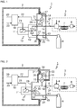
- Fig. 1 illustrates a fluid pressure control apparatus 1 which is partially arranged in an electronics housing or enclosure 2 of, e. g., a process gas chromatograph 3 for analyzing a sample 4.
- the sample 4 is supplied to a dosing unit 5 for injecting a specified dose into a carrier gas stream 6.
- the most commonly used gases as carrier gas for gas chromatograph are nitrogen, hydrogen and helium.
- the carrier gas 6 transports the sample through one or several separation columns 7 where separation of the components of the sample 4 takes place. The gas components successively eluting from the column 7 are detected and quantitatively identified by a detector 8.
- the carrier gas 6 is taken from a gas source 9, here a gas bottle.
- the fluid pressure control apparatus 1 serves to keep the pressure of the carrier gas 6 delivered to the gas chromatograph 3 at a predetermined level to provide an optimum performance over the operating target ranges.
- the pressure control apparatus 1 contains a proportional solenoid valve 10 that has a solenoid portion 11 and a valve portion 12.
- the valve portion 12 is operatively connected between a fluid inlet port 13 to which the gas source 9 is connected and a fluid outlet port 14 to which the dosing unit 5 of the gas chromatograph 3 is connected.
- the fluid inlet port 13 is in fluid communication with an additional fluid port 15 which allows connecting the fluid inlet port of a second fluid pressure control apparatus (not shown) to the gas source 9.
- a differential pressure sensor 16 measures the pressure of the carrier gas 6 at the fluid outlet port 14 against the atmospheric pressure. To that end, the pressure sensor 16 is fluidically coupled to the fluid outlet port 14 on one side and on the other side via an atmosphere inlet port 17 to the surrounding atmosphere. A reference pressure inlet port 18 allows alternatively connecting the pressure sensor 16 to a reference pressure source (not shown). All ports, e. g. 15, 18, which are not used, are closed.
- the pressure control apparatus 1 further contains an electronic controller 19 which is powered via a line 20 and which generates and outputs a control signal 21 to the proportional solenoid valve 10 in dependence on a control deviation between a first signal 22 provided by the pressure sensor 16 and representative of the measured or sensed pressure and a pressure set point value 23.
- the solenoid valve 10 and the electronic controller 19 are arranged inside the enclosure 2.
- the enclosure 2 is designed explosion-proof or may be purged with air or an inert gas to prevent flammable gases from entering the enclosure and/or to dilute and disperse such gases as to render the gas mixture in the enclosure 2 non-explosive.
- the ports 13, 14, 15, 17, 18 are realized as tube fittings on a front side 24 of a manifold block 25 that closes an opening 26 of the enclosure 2 to which it is mounted.
- the manifold block 25 further comprises fluid connectors 27, 28 on a backside 29 facing the inner of the enclosure 2 and internal passageways 30 which connect the fluid connector 27 to the fluid inlet port 13, the fluid connector 28 to the fluid outlet port 14 and further connect the differential pressure sensor 16 between the fluid outlet port 14 and the atmosphere and/or reference pressure inlet port 17, 18.
- valve portion 12 of the solenoid valve 10 is arranged inside the enclosure 2 and permanently joined to the backside 29 of the manifold block 25, where the fluid connectors 27, 28 provide fluid passageways between the valve portion 12 and the manifold block 25.
- the joint is infallible and can be made by, e. g., welding or clamping.
- the first signal 22 provided by the pressure sensor 16 is conducted to the electronic controller 19 in the enclosure 2 via a fluid-tight electrical feedthrough 31 in the manifold block 25.
- Fig. 2 illustrates a second embodiment of the fluid pressure control apparatus 1 that mainly differs from that of Fig. 1 in that the valve portion 12 of the solenoid valve 10 is accommodated in the manifold block 25 and separated from the inner of the enclosure 2.
- the manifold block 25 comprises, at the backside 29, an operational interface 32 in the form of a positioning element between the valve portion 12 and the solenoid portion 11 of the solenoid valve 10.
- the operational interface 32 may comprise a magnetic coupling, e. g., between a coil of solenoid portion 11 and a plunger of the valve portion 12.
- the fluid-tight electrical feedthrough 31 is arranged in the wall of the enclosure 2.
- the cable 33 carrying the first signal 22 through the area outside the enclosure 2 is surrounded by an enclosure 34 that provides a certain ingress protection level.
- Fig. 3 illustrates a third embodiment of the fluid pressure control apparatus 1 that mainly differs from that of Fig. 1 in that pressure sensor 16 is arranged outside both the enclosure 2 and the manifold block 25.
- the pressure sensor 16 is connected to the electronic controller 19 through an intrinsic safety barrier 35 inside the enclosure 2.
Landscapes
- Physics & Mathematics (AREA)
- Engineering & Computer Science (AREA)
- Fluid Mechanics (AREA)
- General Physics & Mathematics (AREA)
- General Engineering & Computer Science (AREA)
- Automation & Control Theory (AREA)
- Mechanical Engineering (AREA)
- Control Of Fluid Pressure (AREA)
Abstract
Description
- The invention relates to a fluid pressure control apparatus.
- The fluid pressure control apparatus of concern herein provides a regulated fluid pressure output that is equal to a pressure set point value applied to the control apparatus. To that end, the apparatus may comprise a proportional solenoid valve operatively connected between a fluid inlet and a fluid outlet and a pressure sensor fluidically coupled to the fluid outlet on one side and on the other side to the surrounding atmosphere. An electronic controller generates and outputs a control signal to the solenoid valve in dependence on a control deviation between the measured or sensed pressure and the pressure set point value.
- The mentioned pressure apparatuses or systems may be used in gas analysis equipment, for example, for regulating a carrier gas flow in a process gas chromatograph. Gas analysis equipment is often located in harsh environment where explosive gases may be present. Thus, safety precautions must be taken to prevent the gases from igniting. To that end, the one or more control apparatuses may be arranged in a pressurized enclosure that uses overpressure to prevent an explosive atmosphere from entering. Alternatively, the enclosure may be designed flameproof/explosion-proof to prevent an explosion occurring inside the enclosure from spreading and igniting the explosive atmosphere surrounding the enclosure.
- The unpublished European Patent Application No.
18196354.7 - The mentioned fluid interface poses several potential leakage sources inside the enclosure, which is not critical as long as nitrogen or helium are used as carrier gas or, more generally, as the gas whose pressure is to be controlled. If, however, hydrogen or another flammable or hazardous gas is used, it may become difficult and costly to meet the requirements of explosion protection.
- According to the invention, this problem is reduced or substantially solved by the fluid pressure control apparatus defined in
claim 1 or the gas chromatograph ofclaim 12. - Further embodiments of the invention are set forth in the remaining claims.
- Thus, a subject of the invention is a fluid pressure control apparatus comprising:
- a proportional solenoid valve having a solenoid portion and a valve portion operatively connected between a fluid inlet and a fluid outlet,
- a pressure sensor fluidically coupled to the fluid outlet,
- an electronic controller adapted to receive a first signal from the pressure sensor, to receive a second signal corresponding to a pressure set point and to generate and output a control signal to the solenoid valve,
- a flameproof/explosion proof or pressurized/purged enclosure in which said electronic controller and at least the solenoid portion of the proportional solenoid valve are housed, and
- a manifold block that
- covers and closes an opening of the enclosure to which it is mounted,
- comprises, at a front side facing outside the enclosure, the fluid inlet port and the fluid outlet port,
- has internal passageways adapted to connect the valve portion of the solenoid valve between the fluid inlet port and the fluid outlet port,
- the pressure sensor being arranged outside the enclosure and
- the first signal being conducted into the enclosure via a fluid-tight electrical feedthrough.
- A subject of invention is also a gas chromatograph comprising at least one such fluid pressure control apparatus.
- As the pressure sensor is arranged outside the enclosure and thus is separated from the inner of the enclosure, the number of potential leakage sources inside the enclosure is reduced to no more than the one between the solenoid valve and the manifold block.
- If, additionally, the valve portion of the solenoid valve is accommodated in the manifold block, there will be no leakage source at all inside the enclosure. In this case, the valve portion of the solenoid valve is actuated by the solenoid portion inside the enclosure through an operational interface at a backside of the manifold block either by mechanical or magnetic force. Alternatively, the valve portion may be housed in the enclosure and permanently joined to the manifold block at a backside of it that faces inside the enclosure. The permanent joint is understood to be made not flexible or via plugs and sockets but by, e. g., welding or brazing so that the valve portion is an infallible containment system considered not to release flammable or hazardous gas into the electronics housing or enclosure.
- The pressure sensor can be arranged outside both the enclosure and the manifold block, e. g., plugged at the front side of the manifold block or located in an equipment to which the pressure regulated gas is provided. Alternatively, the pressure sensor can be accommodated in the manifold block. In both cases, the gas-tight electrical feedthrough may be arranged in the manifold block.
- If the cable or wire that carries the first signal runs outside the enclosure and the manifold block in a hazardous area where explosive gas or dust might be present, the cable or wire may be surrounded by an enclosure that provides a certain ingress protection level. In order to keep the effort involved to a minimum, the pressure sensor may be connected to the electronic controller through an intrinsic safety barrier inside the enclosure.
- The manifold block is preferably one-piece and integrally formed.
- The invention will now be described by way of example and with reference to the accompanying drawing, in which
- Fig. 1
- illustrates a simplified schematic block diagram of a first exemplary fluid pressure control apparatus,
- Fig. 2
- is a second exemplary embodiment of the fluid pressure control apparatus and
- Fig. 3
- is a third exemplary embodiment of the fluid pressure control apparatus.
- In the figures, identical or similar parts or components with the same or similar functions are provided with the same reference numerals. The drawings are schematic, not to scale and the relative dimensions of various elements in the drawings are not to scale.
-
Fig. 1 illustrates a fluidpressure control apparatus 1 which is partially arranged in an electronics housing orenclosure 2 of, e. g., aprocess gas chromatograph 3 for analyzing asample 4. Thesample 4 is supplied to adosing unit 5 for injecting a specified dose into acarrier gas stream 6. The most commonly used gases as carrier gas for gas chromatograph are nitrogen, hydrogen and helium. Thecarrier gas 6 transports the sample through one orseveral separation columns 7 where separation of the components of thesample 4 takes place. The gas components successively eluting from thecolumn 7 are detected and quantitatively identified by adetector 8. - The
carrier gas 6 is taken from agas source 9, here a gas bottle. The fluidpressure control apparatus 1 serves to keep the pressure of thecarrier gas 6 delivered to thegas chromatograph 3 at a predetermined level to provide an optimum performance over the operating target ranges. Thepressure control apparatus 1 contains aproportional solenoid valve 10 that has asolenoid portion 11 and avalve portion 12. Thevalve portion 12 is operatively connected between afluid inlet port 13 to which thegas source 9 is connected and afluid outlet port 14 to which thedosing unit 5 of thegas chromatograph 3 is connected. Thefluid inlet port 13 is in fluid communication with anadditional fluid port 15 which allows connecting the fluid inlet port of a second fluid pressure control apparatus (not shown) to thegas source 9. Adifferential pressure sensor 16 measures the pressure of thecarrier gas 6 at thefluid outlet port 14 against the atmospheric pressure. To that end, thepressure sensor 16 is fluidically coupled to thefluid outlet port 14 on one side and on the other side via anatmosphere inlet port 17 to the surrounding atmosphere. A referencepressure inlet port 18 allows alternatively connecting thepressure sensor 16 to a reference pressure source (not shown). All ports, e. g. 15, 18, which are not used, are closed. - The
pressure control apparatus 1 further contains anelectronic controller 19 which is powered via aline 20 and which generates and outputs acontrol signal 21 to theproportional solenoid valve 10 in dependence on a control deviation between afirst signal 22 provided by thepressure sensor 16 and representative of the measured or sensed pressure and a pressure setpoint value 23. - The
solenoid valve 10 and theelectronic controller 19 are arranged inside theenclosure 2. As thegas chromatograph 3 may be located in a hazardous area where explosive gas or dust might be present, theenclosure 2 is designed explosion-proof or may be purged with air or an inert gas to prevent flammable gases from entering the enclosure and/or to dilute and disperse such gases as to render the gas mixture in theenclosure 2 non-explosive. - The
ports front side 24 of amanifold block 25 that closes anopening 26 of theenclosure 2 to which it is mounted. Themanifold block 25 further comprisesfluid connectors backside 29 facing the inner of theenclosure 2 andinternal passageways 30 which connect thefluid connector 27 to thefluid inlet port 13, thefluid connector 28 to thefluid outlet port 14 and further connect thedifferential pressure sensor 16 between thefluid outlet port 14 and the atmosphere and/or referencepressure inlet port pressure sensor 16 is accommodated inside themanifold block 25 and separated from the inner of theenclosure 2, thevalve portion 12 of thesolenoid valve 10 is arranged inside theenclosure 2 and permanently joined to thebackside 29 of themanifold block 25, where thefluid connectors valve portion 12 and themanifold block 25. The joint is infallible and can be made by, e. g., welding or clamping. - The
first signal 22 provided by thepressure sensor 16 is conducted to theelectronic controller 19 in theenclosure 2 via a fluid-tightelectrical feedthrough 31 in themanifold block 25. -
Fig. 2 illustrates a second embodiment of the fluidpressure control apparatus 1 that mainly differs from that ofFig. 1 in that thevalve portion 12 of thesolenoid valve 10 is accommodated in themanifold block 25 and separated from the inner of theenclosure 2. Themanifold block 25 comprises, at thebackside 29, anoperational interface 32 in the form of a positioning element between thevalve portion 12 and thesolenoid portion 11 of thesolenoid valve 10. - Alternatively, the
operational interface 32 may comprise a magnetic coupling, e. g., between a coil ofsolenoid portion 11 and a plunger of thevalve portion 12. - The fluid-tight
electrical feedthrough 31 is arranged in the wall of theenclosure 2. Thecable 33 carrying thefirst signal 22 through the area outside theenclosure 2 is surrounded by anenclosure 34 that provides a certain ingress protection level. -
Fig. 3 illustrates a third embodiment of the fluidpressure control apparatus 1 that mainly differs from that ofFig. 1 in thatpressure sensor 16 is arranged outside both theenclosure 2 and themanifold block 25. Thepressure sensor 16 is connected to theelectronic controller 19 through anintrinsic safety barrier 35 inside theenclosure 2.
Claims (12)
- A fluid pressure control apparatus (1) comprising:- a proportional solenoid valve (10) having a solenoid portion (11) and a valve portion (12) operatively connected between a fluid inlet (11) and a fluid outlet (12),- a pressure sensor (16) fluidically coupled to the fluid outlet (12),- an electronic controller (19) adapted to receive a first signal (22) from the pressure sensor (16), to receive a second signal (23) corresponding to a pressure set point and to generate and output a control signal (21) to the solenoid valve (10),- a flameproof/explosion proof or pressurized/purged enclosure (2) in which said electronic controller (19) and at least the solenoid portion (11) of the proportional solenoid valve (10) are housed, and- a manifold block (25) that- covers and closes an opening (26) of the enclosure (2) to which it is mounted,- comprises, at a front side (24) facing outside the enclosure (2), the fluid inlet port (13) and the fluid outlet port (14),- has internal passageways (30) adapted to connect the valve portion (12) of the solenoid valve (10) between the fluid inlet port (13) and the fluid outlet port (14),- the pressure sensor (16) being arranged outside the enclosure (2) and- the first signal (22) being conducted into the enclosure (2) via a fluid-tight electrical feedthrough (31).
- The fluid pressure control apparatus (1) of claim 1, wherein the pressure sensor (16) is arranged outside the manifold block (25).
- The fluid pressure control apparatus (1) of claim 1, wherein the pressure sensor (16) is accommodated in the manifold block (25).
- The fluid pressure control apparatus (1) of any one of the preceding claims, wherein the gas-tight electrical feedthrough (31) is arranged in the manifold block (25).
- The fluid pressure control apparatus (1) of any one of the preceding claims, wherein the path of the first signal (22) outside the enclosure (2) and the manifold block (25) is arranged in an enclosure (34) designed to provide protection against ingress.
- The fluid pressure control apparatus (1) of any one of the preceding claims, wherein the pressure sensor (16) is connected to the electronic controller (19) through an intrinsic safety barrier (35) inside the enclosure (2).
- The fluid pressure control apparatus (1) of any one of the preceding claims, wherein the valve portion (12) of the solenoid valve (10) is housed in the enclosure (2) and permanently joined to the manifold block (25) at a backside (29) of it that faces inside the enclosure (2).
- The fluid pressure control apparatus (1) of any one of claim 1 to 6, wherein the valve portion (12) of the solenoid valve (10) is accommodated in the manifold block (25) which, at a backside (29) facing inside the enclosure (2), comprises an operational interface (32) between the valve portion (12) and the solenoid portion (11).
- The fluid pressure control apparatus (1) of claim 8, wherein the operational interface (32) comprises a positioning element.
- The fluid pressure control apparatus (1) of claim 8, wherein the operational interface (32) comprises a magnetic coupling.
- The fluid pressure control apparatus (1) of any one of the preceding claims, wherein the manifold block (25) is one-piece and integrally formed.
- A gas chromatograph (3) comprising at least one at least one fluid pressure control apparatus (1) of one of the preceding claims.
Priority Applications (3)
| Application Number | Priority Date | Filing Date | Title |
|---|---|---|---|
| EP20164731.0A EP3882737B1 (en) | 2020-03-20 | 2020-03-20 | Fluid pressure control apparatus |
| CN202110290709.XA CN113494681B (en) | 2020-03-20 | 2021-03-18 | Fluid pressure control device |
| US17/207,211 US11835973B2 (en) | 2020-03-20 | 2021-03-19 | Fluid pressure control apparatus |
Applications Claiming Priority (1)
| Application Number | Priority Date | Filing Date | Title |
|---|---|---|---|
| EP20164731.0A EP3882737B1 (en) | 2020-03-20 | 2020-03-20 | Fluid pressure control apparatus |
Publications (2)
| Publication Number | Publication Date |
|---|---|
| EP3882737A1 true EP3882737A1 (en) | 2021-09-22 |
| EP3882737B1 EP3882737B1 (en) | 2022-04-27 |
Family
ID=69953796
Family Applications (1)
| Application Number | Title | Priority Date | Filing Date |
|---|---|---|---|
| EP20164731.0A Active EP3882737B1 (en) | 2020-03-20 | 2020-03-20 | Fluid pressure control apparatus |
Country Status (3)
| Country | Link |
|---|---|
| US (1) | US11835973B2 (en) |
| EP (1) | EP3882737B1 (en) |
| CN (1) | CN113494681B (en) |
Cited By (2)
| Publication number | Priority date | Publication date | Assignee | Title |
|---|---|---|---|---|
| CN114115031A (en) * | 2021-11-25 | 2022-03-01 | 上海飞奥燃气设备有限公司 | Intelligent control ware disconnect-type explosion-proof system |
| WO2023052818A1 (en) * | 2021-09-30 | 2023-04-06 | Siemens Aktiengesellschaft | Gas analyzer with improved architecture for operation in potentially hazardous environment |
Families Citing this family (1)
| Publication number | Priority date | Publication date | Assignee | Title |
|---|---|---|---|---|
| WO2025146246A1 (en) * | 2024-01-03 | 2025-07-10 | Dover Fueling Solutions Uk Limited | Cable management in a fuel dispenser |
Citations (3)
| Publication number | Priority date | Publication date | Assignee | Title |
|---|---|---|---|---|
| US20050279408A1 (en) * | 2004-06-18 | 2005-12-22 | Henderson Robert C | Electronically controlled back pressure regulator |
| US20070074865A1 (en) * | 2005-09-30 | 2007-04-05 | Smc Corporation | Constant temperature liquid circulating deivce having external piping protecting function |
| US20160252912A1 (en) * | 2013-03-14 | 2016-09-01 | Christopher Max Horwitz | Pressure-based gas flow controller with dynamic self-calibration |
Family Cites Families (18)
| Publication number | Priority date | Publication date | Assignee | Title |
|---|---|---|---|---|
| US4147333A (en) * | 1977-04-26 | 1979-04-03 | Heath Engineering Company | Programmed pressure regulator for controlling the supply of gas pressure to a load device |
| US5741960A (en) * | 1994-05-27 | 1998-04-21 | Daniel Industries, Inc. | Probe chromatograph apparatus and method |
| US20050150552A1 (en) * | 2004-01-06 | 2005-07-14 | Randy Forshey | Device, method, and system for controlling fluid flow |
| CN101208258A (en) * | 2005-03-04 | 2008-06-25 | 波克爱德华兹股份有限公司 | Control of fluid conditions in a volumetric fluid distribution system |
| JP2007026056A (en) * | 2005-07-15 | 2007-02-01 | Toho Seisakusho:Kk | Fluid pressure regulator |
| US7506533B2 (en) * | 2005-09-02 | 2009-03-24 | Abb Inc. | Gas chromatograph module with an electronic device |
| US7784496B2 (en) * | 2007-06-11 | 2010-08-31 | Lam Research Corporation | Triple valve inlet assembly |
| CN102305351B (en) * | 2011-08-29 | 2012-10-24 | 陶建科 | Pipe network pressure control system |
| EP2618143B1 (en) * | 2012-01-19 | 2015-05-27 | Idexx Laboratories, Inc. | Analyzer with fluid pressure control device |
| EP2825878A4 (en) * | 2012-03-08 | 2016-07-20 | Waters Technologies Corp | COUNTER-PRESSURE CONTROL |
| DE202013007990U1 (en) * | 2013-09-11 | 2013-10-09 | Bürkert Werke GmbH | Electromagnetic actuator for a solenoid valve, valve terminal with at least one solenoid valve and module assembly |
| DE102013221453A1 (en) * | 2013-10-23 | 2015-04-23 | Conti Temic Microelectronic Gmbh | Regulation of a hydraulic pressure of a flow gear |
| CN105334278B (en) * | 2015-12-10 | 2017-05-31 | 新疆工程学院 | Gas chromatograph inlet end trace gas controller |
| CN206943817U (en) * | 2017-06-26 | 2018-01-30 | 国网山东省电力公司威海供电公司 | Oiling test gas circuit controller with warning function |
| CN208503947U (en) * | 2018-05-06 | 2019-02-15 | 苏州康恒检测技术有限公司 | A gas supply device for a gas chromatograph |
| CN208721630U (en) * | 2018-07-27 | 2019-04-09 | 沈阳汉威科技有限公司 | A kind of multipath integrated electronic pressure controller |
| EP3627274B1 (en) | 2018-09-24 | 2020-10-28 | Siemens Aktiengesellschaft | Fluid pressure control apparatus and system |
| EP3629016B1 (en) * | 2018-09-28 | 2023-06-14 | Siemens Aktiengesellschaft | A fluid analyzer |
-
2020
- 2020-03-20 EP EP20164731.0A patent/EP3882737B1/en active Active
-
2021
- 2021-03-18 CN CN202110290709.XA patent/CN113494681B/en active Active
- 2021-03-19 US US17/207,211 patent/US11835973B2/en active Active
Patent Citations (3)
| Publication number | Priority date | Publication date | Assignee | Title |
|---|---|---|---|---|
| US20050279408A1 (en) * | 2004-06-18 | 2005-12-22 | Henderson Robert C | Electronically controlled back pressure regulator |
| US20070074865A1 (en) * | 2005-09-30 | 2007-04-05 | Smc Corporation | Constant temperature liquid circulating deivce having external piping protecting function |
| US20160252912A1 (en) * | 2013-03-14 | 2016-09-01 | Christopher Max Horwitz | Pressure-based gas flow controller with dynamic self-calibration |
Cited By (4)
| Publication number | Priority date | Publication date | Assignee | Title |
|---|---|---|---|---|
| WO2023052818A1 (en) * | 2021-09-30 | 2023-04-06 | Siemens Aktiengesellschaft | Gas analyzer with improved architecture for operation in potentially hazardous environment |
| WO2023052870A1 (en) | 2021-09-30 | 2023-04-06 | Siemens Aktiengesellschaft | Gas analyzer with improved architecture for operation in potentially hazardous environment |
| US12222338B2 (en) | 2021-09-30 | 2025-02-11 | Gas Chromatography Systems Maxum Gmbh | Gas analyzer with improved architecture for operation in potentially hazardous environments |
| CN114115031A (en) * | 2021-11-25 | 2022-03-01 | 上海飞奥燃气设备有限公司 | Intelligent control ware disconnect-type explosion-proof system |
Also Published As
| Publication number | Publication date |
|---|---|
| US11835973B2 (en) | 2023-12-05 |
| CN113494681A (en) | 2021-10-12 |
| EP3882737B1 (en) | 2022-04-27 |
| CN113494681B (en) | 2023-01-24 |
| US20210294359A1 (en) | 2021-09-23 |
Similar Documents
| Publication | Publication Date | Title |
|---|---|---|
| EP3882737B1 (en) | Fluid pressure control apparatus | |
| EP2498877B1 (en) | Inline plug flame arrestors | |
| JP5503911B2 (en) | Gauge type pressure sensor used for dangerous applications | |
| US20070217091A1 (en) | Non-intrinsically safely supplied measurement device | |
| EP4352463B1 (en) | Explosion management display and methods thereof | |
| US6918303B2 (en) | Bi-planar differential pressure transmitter with orthogonal process connections | |
| US11215588B2 (en) | Fluid pressure control apparatus and system | |
| US20130098140A1 (en) | Process analytic instrument with multi-tube connection | |
| US20140102171A1 (en) | Process analytic instrument with encapsulated flame-quenching connection | |
| US7244895B1 (en) | Electrical feedthrough for varied environmental conditions | |
| US10480969B2 (en) | Field device of measuring- and automation technology | |
| WO2023052818A1 (en) | Gas analyzer with improved architecture for operation in potentially hazardous environment | |
| US9620034B2 (en) | Methods and apparatus to expose enclosure labels | |
| EP4711759A1 (en) | Gas chromatograph device, system, and method with modular architecture | |
| KR20250091259A (en) | Fixing structure for wiring or piping | |
| KR100268526B1 (en) | Gas-Processing Equipment | |
| CN108006307A (en) | Intrinsic safety and the separated pneumatic positioner valve of flame proof | |
| US20110180147A1 (en) | Method and apparatus for improved solenoid valves | |
| CN121941967A (en) | Mass flow control system | |
| JPH0440365A (en) | Gas chromatograph |
Legal Events
| Date | Code | Title | Description |
|---|---|---|---|
| PUAI | Public reference made under article 153(3) epc to a published international application that has entered the european phase |
Free format text: ORIGINAL CODE: 0009012 |
|
| STAA | Information on the status of an ep patent application or granted ep patent |
Free format text: STATUS: REQUEST FOR EXAMINATION WAS MADE |
|
| 17P | Request for examination filed |
Effective date: 20210217 |
|
| AK | Designated contracting states |
Kind code of ref document: A1 Designated state(s): AL AT BE BG CH CY CZ DE DK EE ES FI FR GB GR HR HU IE IS IT LI LT LU LV MC MK MT NL NO PL PT RO RS SE SI SK SM TR |
|
| GRAP | Despatch of communication of intention to grant a patent |
Free format text: ORIGINAL CODE: EPIDOSNIGR1 |
|
| STAA | Information on the status of an ep patent application or granted ep patent |
Free format text: STATUS: GRANT OF PATENT IS INTENDED |
|
| INTG | Intention to grant announced |
Effective date: 20211210 |
|
| GRAS | Grant fee paid |
Free format text: ORIGINAL CODE: EPIDOSNIGR3 |
|
| GRAA | (expected) grant |
Free format text: ORIGINAL CODE: 0009210 |
|
| STAA | Information on the status of an ep patent application or granted ep patent |
Free format text: STATUS: THE PATENT HAS BEEN GRANTED |
|
| AK | Designated contracting states |
Kind code of ref document: B1 Designated state(s): AL AT BE BG CH CY CZ DE DK EE ES FI FR GB GR HR HU IE IS IT LI LT LU LV MC MK MT NL NO PL PT RO RS SE SI SK SM TR |
|
| REG | Reference to a national code |
Ref country code: GB Ref legal event code: FG4D |
|
| REG | Reference to a national code |
Ref country code: CH Ref legal event code: EP |
|
| REG | Reference to a national code |
Ref country code: AT Ref legal event code: REF Ref document number: 1487433 Country of ref document: AT Kind code of ref document: T Effective date: 20220515 |
|
| REG | Reference to a national code |
Ref country code: DE Ref legal event code: R096 Ref document number: 602020002791 Country of ref document: DE |
|
| REG | Reference to a national code |
Ref country code: IE Ref legal event code: FG4D |
|
| REG | Reference to a national code |
Ref country code: LT Ref legal event code: MG9D |
|
| REG | Reference to a national code |
Ref country code: NL Ref legal event code: MP Effective date: 20220427 |
|
| REG | Reference to a national code |
Ref country code: AT Ref legal event code: MK05 Ref document number: 1487433 Country of ref document: AT Kind code of ref document: T Effective date: 20220427 |
|
| PG25 | Lapsed in a contracting state [announced via postgrant information from national office to epo] |
Ref country code: NL Free format text: LAPSE BECAUSE OF FAILURE TO SUBMIT A TRANSLATION OF THE DESCRIPTION OR TO PAY THE FEE WITHIN THE PRESCRIBED TIME-LIMIT Effective date: 20220427 |
|
| PG25 | Lapsed in a contracting state [announced via postgrant information from national office to epo] |
Ref country code: SE Free format text: LAPSE BECAUSE OF FAILURE TO SUBMIT A TRANSLATION OF THE DESCRIPTION OR TO PAY THE FEE WITHIN THE PRESCRIBED TIME-LIMIT Effective date: 20220427 Ref country code: PT Free format text: LAPSE BECAUSE OF FAILURE TO SUBMIT A TRANSLATION OF THE DESCRIPTION OR TO PAY THE FEE WITHIN THE PRESCRIBED TIME-LIMIT Effective date: 20220829 Ref country code: NO Free format text: LAPSE BECAUSE OF FAILURE TO SUBMIT A TRANSLATION OF THE DESCRIPTION OR TO PAY THE FEE WITHIN THE PRESCRIBED TIME-LIMIT Effective date: 20220727 Ref country code: LT Free format text: LAPSE BECAUSE OF FAILURE TO SUBMIT A TRANSLATION OF THE DESCRIPTION OR TO PAY THE FEE WITHIN THE PRESCRIBED TIME-LIMIT Effective date: 20220427 Ref country code: HR Free format text: LAPSE BECAUSE OF FAILURE TO SUBMIT A TRANSLATION OF THE DESCRIPTION OR TO PAY THE FEE WITHIN THE PRESCRIBED TIME-LIMIT Effective date: 20220427 Ref country code: GR Free format text: LAPSE BECAUSE OF FAILURE TO SUBMIT A TRANSLATION OF THE DESCRIPTION OR TO PAY THE FEE WITHIN THE PRESCRIBED TIME-LIMIT Effective date: 20220728 Ref country code: FI Free format text: LAPSE BECAUSE OF FAILURE TO SUBMIT A TRANSLATION OF THE DESCRIPTION OR TO PAY THE FEE WITHIN THE PRESCRIBED TIME-LIMIT Effective date: 20220427 Ref country code: BG Free format text: LAPSE BECAUSE OF FAILURE TO SUBMIT A TRANSLATION OF THE DESCRIPTION OR TO PAY THE FEE WITHIN THE PRESCRIBED TIME-LIMIT Effective date: 20220727 Ref country code: AT Free format text: LAPSE BECAUSE OF FAILURE TO SUBMIT A TRANSLATION OF THE DESCRIPTION OR TO PAY THE FEE WITHIN THE PRESCRIBED TIME-LIMIT Effective date: 20220427 |
|
| PG25 | Lapsed in a contracting state [announced via postgrant information from national office to epo] |
Ref country code: RS Free format text: LAPSE BECAUSE OF FAILURE TO SUBMIT A TRANSLATION OF THE DESCRIPTION OR TO PAY THE FEE WITHIN THE PRESCRIBED TIME-LIMIT Effective date: 20220427 Ref country code: PL Free format text: LAPSE BECAUSE OF FAILURE TO SUBMIT A TRANSLATION OF THE DESCRIPTION OR TO PAY THE FEE WITHIN THE PRESCRIBED TIME-LIMIT Effective date: 20220427 Ref country code: LV Free format text: LAPSE BECAUSE OF FAILURE TO SUBMIT A TRANSLATION OF THE DESCRIPTION OR TO PAY THE FEE WITHIN THE PRESCRIBED TIME-LIMIT Effective date: 20220427 Ref country code: IS Free format text: LAPSE BECAUSE OF FAILURE TO SUBMIT A TRANSLATION OF THE DESCRIPTION OR TO PAY THE FEE WITHIN THE PRESCRIBED TIME-LIMIT Effective date: 20220827 |
|
| REG | Reference to a national code |
Ref country code: DE Ref legal event code: R097 Ref document number: 602020002791 Country of ref document: DE |
|
| PG25 | Lapsed in a contracting state [announced via postgrant information from national office to epo] |
Ref country code: SM Free format text: LAPSE BECAUSE OF FAILURE TO SUBMIT A TRANSLATION OF THE DESCRIPTION OR TO PAY THE FEE WITHIN THE PRESCRIBED TIME-LIMIT Effective date: 20220427 Ref country code: SK Free format text: LAPSE BECAUSE OF FAILURE TO SUBMIT A TRANSLATION OF THE DESCRIPTION OR TO PAY THE FEE WITHIN THE PRESCRIBED TIME-LIMIT Effective date: 20220427 Ref country code: RO Free format text: LAPSE BECAUSE OF FAILURE TO SUBMIT A TRANSLATION OF THE DESCRIPTION OR TO PAY THE FEE WITHIN THE PRESCRIBED TIME-LIMIT Effective date: 20220427 Ref country code: ES Free format text: LAPSE BECAUSE OF FAILURE TO SUBMIT A TRANSLATION OF THE DESCRIPTION OR TO PAY THE FEE WITHIN THE PRESCRIBED TIME-LIMIT Effective date: 20220427 Ref country code: EE Free format text: LAPSE BECAUSE OF FAILURE TO SUBMIT A TRANSLATION OF THE DESCRIPTION OR TO PAY THE FEE WITHIN THE PRESCRIBED TIME-LIMIT Effective date: 20220427 Ref country code: DK Free format text: LAPSE BECAUSE OF FAILURE TO SUBMIT A TRANSLATION OF THE DESCRIPTION OR TO PAY THE FEE WITHIN THE PRESCRIBED TIME-LIMIT Effective date: 20220427 Ref country code: CZ Free format text: LAPSE BECAUSE OF FAILURE TO SUBMIT A TRANSLATION OF THE DESCRIPTION OR TO PAY THE FEE WITHIN THE PRESCRIBED TIME-LIMIT Effective date: 20220427 |
|
| PLBE | No opposition filed within time limit |
Free format text: ORIGINAL CODE: 0009261 |
|
| STAA | Information on the status of an ep patent application or granted ep patent |
Free format text: STATUS: NO OPPOSITION FILED WITHIN TIME LIMIT |
|
| PG25 | Lapsed in a contracting state [announced via postgrant information from national office to epo] |
Ref country code: AL Free format text: LAPSE BECAUSE OF FAILURE TO SUBMIT A TRANSLATION OF THE DESCRIPTION OR TO PAY THE FEE WITHIN THE PRESCRIBED TIME-LIMIT Effective date: 20220427 |
|
| 26N | No opposition filed |
Effective date: 20230130 |
|
| PG25 | Lapsed in a contracting state [announced via postgrant information from national office to epo] |
Ref country code: MC Free format text: LAPSE BECAUSE OF FAILURE TO SUBMIT A TRANSLATION OF THE DESCRIPTION OR TO PAY THE FEE WITHIN THE PRESCRIBED TIME-LIMIT Effective date: 20220427 |
|
| PGFP | Annual fee paid to national office [announced via postgrant information from national office to epo] |
Ref country code: CH Payment date: 20230906 Year of fee payment: 4 Ref country code: IE Payment date: 20230920 Year of fee payment: 4 |
|
| PGFP | Annual fee paid to national office [announced via postgrant information from national office to epo] |
Ref country code: FR Payment date: 20230918 Year of fee payment: 4 Ref country code: BE Payment date: 20230920 Year of fee payment: 4 |
|
| PG25 | Lapsed in a contracting state [announced via postgrant information from national office to epo] |
Ref country code: LU Free format text: LAPSE BECAUSE OF NON-PAYMENT OF DUE FEES Effective date: 20230320 |
|
| PG25 | Lapsed in a contracting state [announced via postgrant information from national office to epo] |
Ref country code: IT Free format text: LAPSE BECAUSE OF FAILURE TO SUBMIT A TRANSLATION OF THE DESCRIPTION OR TO PAY THE FEE WITHIN THE PRESCRIBED TIME-LIMIT Effective date: 20220427 |
|
| REG | Reference to a national code |
Ref country code: DE Ref legal event code: R081 Ref document number: 602020002791 Country of ref document: DE Owner name: GAS CHROMATOGRAPHY SYSTEMS MAXUM GMBH, DE Free format text: FORMER OWNER: SIEMENS AKTIENGESELLSCHAFT, 80333 MUENCHEN, DE |
|
| REG | Reference to a national code |
Ref country code: CH Ref legal event code: PL |
|
| PG25 | Lapsed in a contracting state [announced via postgrant information from national office to epo] |
Ref country code: BG Free format text: LAPSE BECAUSE OF FAILURE TO SUBMIT A TRANSLATION OF THE DESCRIPTION OR TO PAY THE FEE WITHIN THE PRESCRIBED TIME-LIMIT Effective date: 20220427 |
|
| GBPC | Gb: european patent ceased through non-payment of renewal fee |
Effective date: 20240320 |
|
| PG25 | Lapsed in a contracting state [announced via postgrant information from national office to epo] |
Ref country code: BG Free format text: LAPSE BECAUSE OF FAILURE TO SUBMIT A TRANSLATION OF THE DESCRIPTION OR TO PAY THE FEE WITHIN THE PRESCRIBED TIME-LIMIT Effective date: 20220427 |
|
| REG | Reference to a national code |
Ref country code: BE Ref legal event code: MM Effective date: 20240331 |
|
| PG25 | Lapsed in a contracting state [announced via postgrant information from national office to epo] |
Ref country code: BE Free format text: LAPSE BECAUSE OF NON-PAYMENT OF DUE FEES Effective date: 20240331 |
|
| PG25 | Lapsed in a contracting state [announced via postgrant information from national office to epo] |
Ref country code: GB Free format text: LAPSE BECAUSE OF NON-PAYMENT OF DUE FEES Effective date: 20240320 |
|
| PG25 | Lapsed in a contracting state [announced via postgrant information from national office to epo] |
Ref country code: FR Free format text: LAPSE BECAUSE OF NON-PAYMENT OF DUE FEES Effective date: 20240331 |
|
| PG25 | Lapsed in a contracting state [announced via postgrant information from national office to epo] |
Ref country code: IE Free format text: LAPSE BECAUSE OF NON-PAYMENT OF DUE FEES Effective date: 20240320 |
|
| PG25 | Lapsed in a contracting state [announced via postgrant information from national office to epo] |
Ref country code: IE Free format text: LAPSE BECAUSE OF NON-PAYMENT OF DUE FEES Effective date: 20240320 Ref country code: GB Free format text: LAPSE BECAUSE OF NON-PAYMENT OF DUE FEES Effective date: 20240320 Ref country code: FR Free format text: LAPSE BECAUSE OF NON-PAYMENT OF DUE FEES Effective date: 20240331 Ref country code: BE Free format text: LAPSE BECAUSE OF NON-PAYMENT OF DUE FEES Effective date: 20240331 Ref country code: CH Free format text: LAPSE BECAUSE OF NON-PAYMENT OF DUE FEES Effective date: 20240331 |
|
| PGFP | Annual fee paid to national office [announced via postgrant information from national office to epo] |
Ref country code: DE Payment date: 20250319 Year of fee payment: 6 |
|
| PG25 | Lapsed in a contracting state [announced via postgrant information from national office to epo] |
Ref country code: CY Free format text: LAPSE BECAUSE OF FAILURE TO SUBMIT A TRANSLATION OF THE DESCRIPTION OR TO PAY THE FEE WITHIN THE PRESCRIBED TIME-LIMIT; INVALID AB INITIO Effective date: 20200320 |
|
| PG25 | Lapsed in a contracting state [announced via postgrant information from national office to epo] |
Ref country code: HU Free format text: LAPSE BECAUSE OF FAILURE TO SUBMIT A TRANSLATION OF THE DESCRIPTION OR TO PAY THE FEE WITHIN THE PRESCRIBED TIME-LIMIT; INVALID AB INITIO Effective date: 20200320 |
|
| PG25 | Lapsed in a contracting state [announced via postgrant information from national office to epo] |
Ref country code: TR Free format text: LAPSE BECAUSE OF FAILURE TO SUBMIT A TRANSLATION OF THE DESCRIPTION OR TO PAY THE FEE WITHIN THE PRESCRIBED TIME-LIMIT Effective date: 20220427 |
|
| PG25 | Lapsed in a contracting state [announced via postgrant information from national office to epo] |
Ref country code: SI Free format text: LAPSE BECAUSE OF FAILURE TO SUBMIT A TRANSLATION OF THE DESCRIPTION OR TO PAY THE FEE WITHIN THE PRESCRIBED TIME-LIMIT Effective date: 20220427 |