EP3882624B1 - Gas concentration sensor - Google Patents
Gas concentration sensor Download PDFInfo
- Publication number
- EP3882624B1 EP3882624B1 EP19905013.9A EP19905013A EP3882624B1 EP 3882624 B1 EP3882624 B1 EP 3882624B1 EP 19905013 A EP19905013 A EP 19905013A EP 3882624 B1 EP3882624 B1 EP 3882624B1
- Authority
- EP
- European Patent Office
- Prior art keywords
- enclosure
- ventilation holes
- sensor
- disposed
- cylindrical body
- Prior art date
- Legal status (The legal status is an assumption and is not a legal conclusion. Google has not performed a legal analysis and makes no representation as to the accuracy of the status listed.)
- Active
Links
Images




Classifications
-
- G—PHYSICS
- G01—MEASURING; TESTING
- G01N—INVESTIGATING OR ANALYSING MATERIALS BY DETERMINING THEIR CHEMICAL OR PHYSICAL PROPERTIES
- G01N29/00—Investigating or analysing materials by the use of ultrasonic, sonic or infrasonic waves; Visualisation of the interior of objects by transmitting ultrasonic or sonic waves through the object
- G01N29/02—Analysing fluids
-
- G—PHYSICS
- G01—MEASURING; TESTING
- G01N—INVESTIGATING OR ANALYSING MATERIALS BY DETERMINING THEIR CHEMICAL OR PHYSICAL PROPERTIES
- G01N29/00—Investigating or analysing materials by the use of ultrasonic, sonic or infrasonic waves; Visualisation of the interior of objects by transmitting ultrasonic or sonic waves through the object
- G01N29/02—Analysing fluids
- G01N29/024—Analysing fluids by measuring propagation velocity or propagation time of acoustic waves
-
- G—PHYSICS
- G01—MEASURING; TESTING
- G01N—INVESTIGATING OR ANALYSING MATERIALS BY DETERMINING THEIR CHEMICAL OR PHYSICAL PROPERTIES
- G01N29/00—Investigating or analysing materials by the use of ultrasonic, sonic or infrasonic waves; Visualisation of the interior of objects by transmitting ultrasonic or sonic waves through the object
- G01N29/22—Details, e.g. general constructional or apparatus details
- G01N29/222—Constructional or flow details for analysing fluids
-
- G—PHYSICS
- G01—MEASURING; TESTING
- G01N—INVESTIGATING OR ANALYSING MATERIALS BY DETERMINING THEIR CHEMICAL OR PHYSICAL PROPERTIES
- G01N29/00—Investigating or analysing materials by the use of ultrasonic, sonic or infrasonic waves; Visualisation of the interior of objects by transmitting ultrasonic or sonic waves through the object
- G01N29/22—Details, e.g. general constructional or apparatus details
- G01N29/24—Probes
-
- G—PHYSICS
- G01—MEASURING; TESTING
- G01N—INVESTIGATING OR ANALYSING MATERIALS BY DETERMINING THEIR CHEMICAL OR PHYSICAL PROPERTIES
- G01N29/00—Investigating or analysing materials by the use of ultrasonic, sonic or infrasonic waves; Visualisation of the interior of objects by transmitting ultrasonic or sonic waves through the object
- G01N29/22—Details, e.g. general constructional or apparatus details
- G01N29/32—Arrangements for suppressing undesired influences, e.g. temperature or pressure variations, compensating for signal noise
-
- G—PHYSICS
- G01—MEASURING; TESTING
- G01N—INVESTIGATING OR ANALYSING MATERIALS BY DETERMINING THEIR CHEMICAL OR PHYSICAL PROPERTIES
- G01N29/00—Investigating or analysing materials by the use of ultrasonic, sonic or infrasonic waves; Visualisation of the interior of objects by transmitting ultrasonic or sonic waves through the object
- G01N29/44—Processing the detected response signal, e.g. electronic circuits specially adapted therefor
-
- G—PHYSICS
- G01—MEASURING; TESTING
- G01N—INVESTIGATING OR ANALYSING MATERIALS BY DETERMINING THEIR CHEMICAL OR PHYSICAL PROPERTIES
- G01N2291/00—Indexing codes associated with group G01N29/00
- G01N2291/02—Indexing codes associated with the analysed material
- G01N2291/021—Gases
- G01N2291/0215—Mixtures of three or more gases, e.g. air
-
- G—PHYSICS
- G01—MEASURING; TESTING
- G01N—INVESTIGATING OR ANALYSING MATERIALS BY DETERMINING THEIR CHEMICAL OR PHYSICAL PROPERTIES
- G01N2291/00—Indexing codes associated with group G01N29/00
- G01N2291/02—Indexing codes associated with the analysed material
- G01N2291/028—Material parameters
- G01N2291/02809—Concentration of a compound, e.g. measured by a surface mass change
-
- G—PHYSICS
- G01—MEASURING; TESTING
- G01N—INVESTIGATING OR ANALYSING MATERIALS BY DETERMINING THEIR CHEMICAL OR PHYSICAL PROPERTIES
- G01N2291/00—Indexing codes associated with group G01N29/00
- G01N2291/10—Number of transducers
- G01N2291/101—Number of transducers one transducer
-
- Y—GENERAL TAGGING OF NEW TECHNOLOGICAL DEVELOPMENTS; GENERAL TAGGING OF CROSS-SECTIONAL TECHNOLOGIES SPANNING OVER SEVERAL SECTIONS OF THE IPC; TECHNICAL SUBJECTS COVERED BY FORMER USPC CROSS-REFERENCE ART COLLECTIONS [XRACs] AND DIGESTS
- Y02—TECHNOLOGIES OR APPLICATIONS FOR MITIGATION OR ADAPTATION AGAINST CLIMATE CHANGE
- Y02A—TECHNOLOGIES FOR ADAPTATION TO CLIMATE CHANGE
- Y02A50/00—TECHNOLOGIES FOR ADAPTATION TO CLIMATE CHANGE in human health protection, e.g. against extreme weather
- Y02A50/20—Air quality improvement or preservation, e.g. vehicle emission control or emission reduction by using catalytic converters
-
- Y—GENERAL TAGGING OF NEW TECHNOLOGICAL DEVELOPMENTS; GENERAL TAGGING OF CROSS-SECTIONAL TECHNOLOGIES SPANNING OVER SEVERAL SECTIONS OF THE IPC; TECHNICAL SUBJECTS COVERED BY FORMER USPC CROSS-REFERENCE ART COLLECTIONS [XRACs] AND DIGESTS
- Y02—TECHNOLOGIES OR APPLICATIONS FOR MITIGATION OR ADAPTATION AGAINST CLIMATE CHANGE
- Y02E—REDUCTION OF GREENHOUSE GAS [GHG] EMISSIONS, RELATED TO ENERGY GENERATION, TRANSMISSION OR DISTRIBUTION
- Y02E60/00—Enabling technologies; Technologies with a potential or indirect contribution to GHG emissions mitigation
- Y02E60/30—Hydrogen technology
- Y02E60/50—Fuel cells
Definitions
- the present invention relates to a gas concentration sensor including an ultrasonic transducer, and more particularly to a configuration of a space into which mixture gas such as air containing gas that is a target of concentration measurement or detection flows.
- Fuel cell vehicles that travel with electric power supplied from a fuel cell have been studied and developed widely. Fuel cells produce electric power through a chemical reaction of hydrogen and oxygen. Typically, hydrogen is supplied to a fuel cell as a fuel, while oxygen is taken from surrounding air into the fuel cell.
- a fuel cell vehicle includes a hydrogen tank from which hydrogen is supplied to the fuel cell. When the hydrogen tank is short of hydrogen, hydrogen is supplied to the hydrogen tank of a fuel cell vehicle from a hydrogen supply apparatus installed at a hydrogen station.
- Hydrogen sensors are therefore widely used along with fuel cell vehicles and hydrogen supply apparatuses.
- the hydrogen sensors measure the concentration of hydrogen contained in air and issue an alarm in response to the hydrogen concentration exceeding a predetermined value.
- abnormality is tested for by detecting leakage of helium while allowing helium to communicate within the apparatuses.
- Such a test is performed with various types of helium sensors, as helium detectors.
- Helium sensors similar to hydrogen sensors, measure the concentration of helium contained in air or detect the concentration of helium exceeding a predetermined value.
- the JP 2002 214203 A , JP H03 223669 A , JP 2002 31621 A and JP 2002 257801 A disclose apparatuses that measure the concentration of specific gas.
- the apparatuses disclosed in these patent documents measure the concentration of specific gas based on propagation properties of ultrasound, such as a propagation velocity of ultrasound, in mixture gas such as air to be measured, and may be used for measurement of the concentration of hydrogen and helium, for example.
- JP H08 201357 A , JP 2008 026067 A , JP 2002 031621 A and WO 2018/188 665A1 disclose gas concentration sensors having a cylindrical shape of a sensing chamber wherein ventilation holes are provided for the gas to be measured to enter the measuring chamber.
- Apparatuses that measure the concentration of specific gas based on the propagation velocity of ultrasound typically include a space in which the concentration of the gas is measured.
- This concentration measurement space includes an ultrasonic transducer that transmits and receives ultrasound.
- the propagation velocity of ultrasound is determined based on a propagation time, which is a time between transmission of ultrasound from a transmitting ultrasonic transducer and reception of ultrasound having propagated within the concentration measurement space by a receiving ultrasonic transducer, and a predetermined propagation distance.
- An object of the present invention is to measure the gas concentration with high accuracy.
- the present invention provides a gas concentration sensor with the features of claim 1 that inter alia includes a cylindrical body; an ultrasonic transducer disposed at a first end of the cylindrical body; an ultrasonic wave reflecting surface disposed at a second end of the cylindrical body and intersecting an axial direction of the cylindrical body; and a plurality of ventilation holes disposed in a peripheral wall of the cylindrical body.
- the plurality of ventilation holes have corresponding through lines each extending in a direction perpendicular to an axial section of the cylindrical body, the through lines of the plurality of ventilation holes pass different locations, and each of the ventilation holes has a shape extending in the axial direction of the cylindrical body.
- the present invention enables highly accurate measurements of the gas concentration.
- FIG. 1 illustrates a gas concentration measurement apparatus 1 according to a first embodiment of the present invention.
- the gas concentration measurement apparatus 1 includes a gas sensor 10 and a body 12.
- the gas sensor 10 includes a sensor enclosure 14 containing an ultrasonic transducer.
- the sensor enclosure 14 has a hollow cylindrical shape, that is, a column shape with a closed top.
- the sensor enclosure 14 includes, on its peripheral wall, ventilation holes 16 through which mixture gas such as air is allowed to flow into the sensor enclosure 14. Under the control of the body 12, ultrasound is transmitted from the ultrasonic transducer to the interior of the sensor enclosure 14, and the ultrasound reflected within the sensor enclosure 14 is received by the ultrasonic transducer.
- the body 12 determines, based on the time when the ultrasonic transducer transmits ultrasound and the time when the ultrasonic transducer receives the ultrasound, a propagation time corresponding to a round-trip propagation time of ultrasound within the sensor enclosure 14, and determines, based on the propagation time, the concentration of target gas.
- FIG. 2 is a perspective view of the gas sensor 10.
- the sensor enclosure 14 includes a front enclosure 18 and a rear enclosure 20.
- the front enclosure 18 has an arch shaped upper part, corresponding to three-quarters of a front face of the sensor enclosure 14.
- a rear face of the front enclosure 18 and a front face of the rear enclosure 20 are engaged with each other to form the sensor enclosure 14.
- the front enclosure 18 and the rear enclosure 20 include a plurality of ventilation holes 16 for communication between the inside and the outside of the sensor enclosure 14.
- Each ventilation hole 16 extends along the axis of the cylindrical shape of the sensor enclosure 14.
- each ventilation hole 16 has a vertical length that is longer than a lateral length (width).
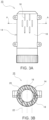
- FIG. 3A is a front view of the gas sensor 10, and FIG. 3B is a cross section (a cross section perpendicular to the axial direction) taken along AA line in FIG. 3A .
- the gas sensor 10 includes, on its front face, seven ventilation holes 16 arranged in three rows: two ventilation holes 16 arranged laterally in an upper row; three ventilation holes 16 arranged laterally in a middle row; and two ventilation holes 16 arranged laterally in a lower row.
- the ventilation hole 16 on the left in the upper row is disposed above a space between the ventilation hole 16 on the left in the middle row and the ventilation hole 16 at the center in the middle row
- the ventilation hole 16 on the right in the upper row is disposed above a space between the ventilation hole 16 on the right in the middle row and the ventilation hole 16 at the center in the middle row
- the ventilation hole 16 on the left in the lower row is disposed below a space between the ventilation hole 16 on the left in the middle row and the ventilation hole 16 at the center in the middle row
- the ventilation hole 16 on the right in the lower row is disposed below a space between the ventilation hole 16 on the right in the middle row and the ventilation hole 16 at the center in the middle row.
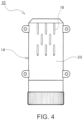
- FIG. 4 is a rear view of the gas sensor 10.
- the gas sensor 10 includes, on its rear face, eight ventilation holes 16 arranged in three rows: three ventilation holes 16 arranged laterally in an upper row; two ventilation holes 16 laterally arranged in a middle row; and three ventilation holes 16 laterally arranged in a lower row.
- the ventilation hole 16 on the left in the middle row is disposed below a space between the ventilation hole 16 on the left in the upper row and the ventilation hole 16 at the center in the upper row, that is, above a space between the ventilation hole 16 on the left in the lower row and the ventilation hole 16 at the center in the lower row.
- the ventilation hole 16 on the right in the middle row is disposed below a space between the ventilation hole 16 on the right in the upper row and the ventilation hole 16 at the center in the upper row. that is, above a space between the ventilation hole 16 on the right in the lower row and the ventilation hole 16 at the center in the lower row.
- the ventilation holes 16 on the left and right and at the center in the upper row are disposed above the ventilation holes 16 on the left and right and at the center in the lower row, respectively, via a region where the ventilation holes 16 in the middle row are arranged.
- FIG. 3B shows, with dashed and double-dotted lines, through lines 22 extending through the ventilation holes 16 and perpendicular to the axial section of the sensor enclosure 14, which is a plane parallel to the front and rear faces.
- the through line 22 is a straight line extending in the same direction as the through direction of the ventilation hole 16.
- the through lines 22 extending from the respective ventilation holes 16 pass through different locations. Therefore, the ventilation holes 16 disposed on the front enclosure 18 and the ventilation holes 16 disposed on the rear enclosure 20 do not exist on the same through lines 22.
- FIG. 5 illustrates a front view of the gas sensor 10 with the front enclosure 18 being removed.
- the gas sensor 10 includes an ultrasonic transducer 30 in a region below a region where the ventilation holes 16 are disposed in the rear enclosure 20.
- the rear enclosure 20 includes, at its upper end, a top board 40 having a board face perpendicular to the axial direction of the sensor enclosure 14.
- the front enclosure 18 is fitted to the rear enclosure 20 from the front, to thereby form the sensor enclosure 14.
- the sensor enclosure 14 formed from the front enclosure 18 and the rear enclosure 20 includes a cylindrical body 42, as a cylindrical member, having an upper end closed with the top board 40.
- the ultrasonic transducer 30 is disposed toward the lower end of the cylindrical body 42, and an ultrasound propagation path along which ultrasound propagates is formed between the ultrasonic transducer 30 and the top board 40.
- the sensor enclosure 14 further includes a plurality of ventilation holes 16 on the peripheral wall of the cylindrical body 42.
- the ratio of the area of openings of all the ventilation holes 16 with respect to the area of the peripheral face of the sensor enclosure 14 may be 6% or greater and 20% or less, and preferably 8% or greater and 15% or less.
- a belt-shaped ventilation region surrounding the peripheral face of the sensor enclosure 14, where the ventilation holes 16 are disposed, may have an area which is 25% of the area of the peripheral face of the sensor enclosure 14.
- the number of ventilation holes 16 in the ventilation region may be, for example, one or more and six or less per 1cm 2 , and preferably two or more and five or less per 1cm 2 .
- FIG. 5 is an axial cross section of the gas sensor 10, operation of the gas sensor 10 will be described.
- the ventilation holes 16 disposed in the sensor enclosure 14 ventilate the internal space of the sensor enclosure 14 serving as a concentration measurement space. Specifically, the air outside the sensor enclosure 14 flows through the ventilation holes 16 disposed in the sensor enclosure 14 into the sensor enclosure 14. The air inside the sensor enclosure 14 flows through the ventilation holes 16 disposed in the sensor enclosure 14 out of the sensor enclosure 14. To facilitate ventilation of the air, a user may move the gas concentration measurement apparatus 1 (see FIG. 1 ) in the air.
- the ultrasonic transducer 30 transmits ultrasound based on a transmitting signal output from a controller included in the body 12 illustrated in FIG. 1 .
- the ultrasound transmitted from the ultrasonic transducer 30 propagates along the ultrasound propagation path formed by the cylindrical body 42 and is reflected by a lower face (an ultrasonic wave reflecting surface 44 intersecting the axial direction of the cylindrical body 42) of the top board 40.
- the ultrasound reflected by the ultrasonic wave reflecting surface 44 propagates along the ultrasound propagation path toward the ultrasonic transducer 30, and is then received by the ultrasonic transducer 30.
- the ultrasonic transducer 30 converts the reflected ultrasound to a received signal and outputs the received signal to the controller.
- the controller determines, based on a time when the controller outputs the transmitting signal and a time when the ultrasonic transducer 30 outputs the received signal, a round-trip propagation time which the ultrasound takes to propagate between the ultrasonic transducer 30 and the ultrasonic wave reflecting surface 44.
- the controller further determines a propagation velocity of the ultrasound along the ultrasound propagation path based on the distance between the ultrasonic transducer 30 and the ultrasonic wave reflecting surface 44 and the round-trip propagation time, and then further determines the concentration of target gas to be measured based on the propagation velocity.
- each ventilation hole 16 extends in the front-rear direction through the peripheral wall of the sensor enclosure 14.
- the ventilation holes 16 disposed in the front enclosure 18 and the ventilation holes 16 disposed in the rear enclosure 20 do not exist on common through lines 22.
- the flow of air flowing into the gas sensor 10 through the ventilation holes 16 disposed in the front enclosure 18 and attempting to flow out through the ventilation holes 16 disposed in the rear enclosure 20 is therefore blocked by a region of the rear enclosure 20 where the ventilation holes 16 are not disposed.
- the flow of air flowing into the gas sensor 10 through the ventilation holes 16 disposed in the rear enclosure 20 and attempting to flow out through the ventilation holes 16 disposed in the front enclosure 18 is blocked by a region of the front enclosure 18 where the ventilation holes 16 are not disposed.
- This configuration maintains ventilation of the interior of the sensor enclosure 14 and simultaneously prevents rapid inflow of the air to be measured into the sensor enclosure 14, thereby reducing a change in the propagation velocity and propagation direction of ultrasound within the sensor enclosure 14. This prevents an error in the time in which the ultrasound makes a round-trip within the concentration measurement space, thereby reducing an error in gas concentration measurement.
- the ventilation holes 16 extending along the axial direction of the cylindrical shape of the sensor enclosure 14 facilitate ventilation of the interior of the sensor enclosure 14 which is axially elongated.
- each ventilation hole 16 need not extend perpendicularly to the axial cross section, or the through lines 22 need not extend from the corresponding ventilation holes 16 toward the same direction.
- the depth direction of each ventilation hole 16 need not be normal to the axial cross section, or the through lines 22 need not extend in the same direction from the ventilation holes 16.
- each ventilation hole 16 may extend in a direction perpendicular to the peripheral face of the sensor enclosure 14.
- the ventilation hole 16 in the rear enclosure 20 may be disposed at locations out of the line of sight directed from the ventilation holes 16 in the front enclosure 18 toward the rear face.
- the ventilation holes 16 in the front enclosure 18 may be disposed at locations out of the line of sight directed from the ventilation holes 16 in the rear enclosure 20 toward the front face.
- the plurality of ventilation holes 16 may be disposed such that a first side of the sensor enclosure 14 is not visible from an opposite second side of the sensor enclosure 14 through the ventilation holes 16 viewed from the peripheral wall
- the aperture ratio of a single ventilation hole 16 was in the range from 0.68% to 0.78%, the aperture ratio of all ventilation holes 16 was 10.9%, and the number of ventilation holes 16 per 1cm 2 was 1.3, a detection time was 4.5 seconds, and an exhaust time was 19 seconds.
- the detection time refers to a time between when the gas sensor 10 was placed in air containing 5% of helium and when 90% of the convergence value of concentration measurements was reached.
- the exhaust time refers to a time starting from a state where the gas sensor 10 was placed in air containing 5% of helium and the concentration measurement corresponded to the convergence value to when the gas sensor 10 was placed in air containing no helium and the concentration measurement was 0. Further, in an experiment in which the aperture ratio of a single ventilation hole 16 was in the range from 0.55% to 0.62%, the aperture ratio of all ventilation holes 16 was 8.8%, and the number of ventilation holes 16 per 1cm 2 was 1.3, the detection time was 7 seconds and the exhaust time was 27 seconds.
- FIG. 6 illustrates a perspective view of a gas sensor 50 according to an example that serves to explain certain aspects of the present invention.
- FIG. 7A illustrates a front view of the gas sensor 50
- FIG. 7B illustrates a cross section along a line BB in FIG. 7A .
- the gas sensor 50 includes a lattice-shape rib structure 54 on a peripheral face of a sensor enclosure 52.
- the rib structure 54 includes circumferential protrusions 56 surrounding the sensor enclosure 52 and vertical protrusions 58 which are linear protrusions extending vertically, and has a lattice shape.
- a plurality of circumferential protrusions 56 are formed on the peripheral face of the sensor enclosure 52 at predetermined intervals, and adjacent circumferential protrusions 56 are coupled by a plurality of vertical protrusions 58 arranged in the circumferential direction at predetermined intervals.
- the plurality of vertical protrusions 58 are arranged vertically in straight lines and disposed at predetermined intervals in the circumferential direction. As illustrated in FIG. 7B , the vertical protrusions 58 protrude from the peripheral face of the sensor enclosure 52 in the same direction as the through direction of the ventilation holes 16.
- the openings of the ventilation holes 16 are located in a region enclosed by adjacent circumferential protrusions 56 and adjacent vertical protrusions 58.
- the circumferential protrusions 56 and the vertical protrusions 58 may traverse the openings of the ventilation holes 16.
- the lattice-shape rib structure 54 disposed on the peripheral face of the sensor enclosure 52 provides the following advantages. Specifically, the air attempting to flow into the sensor enclosure 52 from diagonally upward or diagonally downward is directed by the circumferential protrusions 56 in a direction perpendicular to the periphery of the sensor enclosure 52. This reduces the flow of air flowing into the sensor enclosure 52 from diagonally upward or downward through the ventilation holes 16 disposed in the front enclosure 60 and flowing out through the ventilation holes 16 disposed downward or upward in the rear enclosure 62. This configuration similarly reduces the flow of air flowing into the sensor enclosure 52 diagonally upward or downward through the ventilation holes 16 disposed in the rear enclosure 62 and flowing out through the ventilation holes 16 disposed downward or upward in the front enclosure 60. Thus, the circumferential protrusions 56 reduce passage of the diagonally upward or downward air with respect to the sensor enclosure 52 through the sensor enclosure 52.
- the air to flow into the sensor enclosure 52 from the right or left of the ventilation hole 16 is directed by the vertical protrusion 58 in a direction perpendicular to the peripheral face of the sensor enclosure 52.
- This configuration similarly prevents the flow of air flowing into the ventilation holes 16 disposed on the rear enclosure 62 from diagonally rearward right or left and flowing out of the ventilation holes 16 on the left or right disposed in the front enclosure 60.
- the vertical protrusions 58 thus reduce passage of the air in the diagonally right and left directions with respect to the front face or the rear face of the sensor enclosure 52.
- the rib structure 54 formed on the peripheral face of the sensor enclosure 52 prevents rapid flow of the mixture gas such as air to be measured into the sensor enclosure 52 to reduce a change of the propagation velocity of ultrasound within the sensor enclosure 52. More specifically, the circumferential protrusions 56 prevent the flow of air passing through the ventilation holes 16 having an axial length greater than its lateral width, diagonally upward or downward. The vertical protrusions 58 prevent the flow of air passing through the ventilation holes 16 having a lateral width greater than its axial length, from diagonally forward left or rearward right, or from diagonally rearward left or forward right. This results in a reduction in an error of time during which the ultrasound propagates the concentration measurement space to thereby reduce an error in the gas concentration measurements. The rib structure 54 formed on the peripheral face of the sensor enclosure 52 further enhances the mechanical strength of the sensor enclosure 52.
- the sensor enclosure (14, 52) has a hollow cylindrical shape
- the sensor enclosure (14, 52) may have a shape of a hollow polygonal cylinder or a hollow elliptical cylinder, for example.
- the ventilation hole 16 has a shape extending along the axis of the sensor enclosure (14, 52), but the ventilation hole 16 may have a shape of an ellipse, or a rectangle, for example.
- the cylindrical body may include, on its inner peripheral face corresponding to the peripheral face, a gas-liquid separation membrane formed of a hollow fiber membrane such as PTFE, PP, PE, silicone resin, for example, attached to the inner peripheral face, to thereby prevent entrance of water droplets and dust into the gas concentration measurement space within the cylindrical body.
- a gas-liquid separation membrane formed of a hollow fiber membrane such as PTFE, PP, PE, silicone resin, for example, attached to the inner peripheral face, to thereby prevent entrance of water droplets and dust into the gas concentration measurement space within the cylindrical body.
Landscapes
- Physics & Mathematics (AREA)
- Biochemistry (AREA)
- Health & Medical Sciences (AREA)
- Life Sciences & Earth Sciences (AREA)
- Chemical & Material Sciences (AREA)
- Analytical Chemistry (AREA)
- General Health & Medical Sciences (AREA)
- General Physics & Mathematics (AREA)
- Immunology (AREA)
- Pathology (AREA)
- Acoustics & Sound (AREA)
- Engineering & Computer Science (AREA)
- Signal Processing (AREA)
- Investigating Or Analyzing Materials By The Use Of Ultrasonic Waves (AREA)
Description
- The present invention relates to a gas concentration sensor including an ultrasonic transducer, and more particularly to a configuration of a space into which mixture gas such as air containing gas that is a target of concentration measurement or detection flows.
- Fuel cell vehicles that travel with electric power supplied from a fuel cell have been studied and developed widely. Fuel cells produce electric power through a chemical reaction of hydrogen and oxygen. Typically, hydrogen is supplied to a fuel cell as a fuel, while oxygen is taken from surrounding air into the fuel cell. A fuel cell vehicle includes a hydrogen tank from which hydrogen is supplied to the fuel cell. When the hydrogen tank is short of hydrogen, hydrogen is supplied to the hydrogen tank of a fuel cell vehicle from a hydrogen supply apparatus installed at a hydrogen station.
- It is necessary to monitor leakage of hydrogen, which is flammable gas, from fuel cell vehicles and hydrogen supply apparatuses. Hydrogen sensors are therefore widely used along with fuel cell vehicles and hydrogen supply apparatuses. The hydrogen sensors measure the concentration of hydrogen contained in air and issue an alarm in response to the hydrogen concentration exceeding a predetermined value.
- For apparatuses in which fluid circulates, such as a radiator or vacuum device of automobiles, abnormality is tested for by detecting leakage of helium while allowing helium to communicate within the apparatuses. Such a test is performed with various types of helium sensors, as helium detectors. Helium sensors, similar to hydrogen sensors, measure the concentration of helium contained in air or detect the concentration of helium exceeding a predetermined value.
- The
JP 2002 214203 A JP H03 223669 A JP 2002 31621 A JP 2002 257801 A -
JP H08 201357 A JP 2008 026067 A JP 2002 031621 A WO 2018/188 665A1 disclose gas concentration sensors having a cylindrical shape of a sensing chamber wherein ventilation holes are provided for the gas to be measured to enter the measuring chamber. - Apparatuses that measure the concentration of specific gas based on the propagation velocity of ultrasound typically include a space in which the concentration of the gas is measured. This concentration measurement space includes an ultrasonic transducer that transmits and receives ultrasound. The propagation velocity of ultrasound is determined based on a propagation time, which is a time between transmission of ultrasound from a transmitting ultrasonic transducer and reception of ultrasound having propagated within the concentration measurement space by a receiving ultrasonic transducer, and a predetermined propagation distance.
- While it is necessary to allow mixture gas such as air to be measured to externally flow into the concentration measurement space, sudden inflow of the air to be measured into the space may significantly change the propagation velocity and propagation direction of ultrasound, causing an error in measurements of the gas concentration.
- An object of the present invention is to measure the gas concentration with high accuracy.
- The present invention provides a gas concentration sensor with the features of
claim 1 that inter alia includes a cylindrical body; an ultrasonic transducer disposed at a first end of the cylindrical body; an ultrasonic wave reflecting surface disposed at a second end of the cylindrical body and intersecting an axial direction of the cylindrical body; and a plurality of ventilation holes disposed in a peripheral wall of the cylindrical body. The plurality of ventilation holes have corresponding through lines each extending in a direction perpendicular to an axial section of the cylindrical body, the through lines of the plurality of ventilation holes pass different locations, and each of the ventilation holes has a shape extending in the axial direction of the cylindrical body. - The present invention enables highly accurate measurements of the gas concentration.
-
-
FIG. 1 illustrates a gas concentration measurement apparatus. -
FIG. 2 is a perspective view of a gas sensor. -
FIG. 3A is a front view of the gas sensor. -
FIG. 3B illustrates a cross section of the gas sensor along a direction perpendicular to the axial direction. -
FIG. 4 illustrates a rear view of the gas sensor. -
FIG. 5 is a front view of the gas sensor with a front casing being removed. -
FIG. 6 is a perspective view of a gas sensor. -
FIG. 7A is a front view of a gas sensor. -
FIG. 7B is a cross section of a gas sensor along a direction perpendicular to the axial direction. - Each embodiment of the present invention will be described with reference to the drawings. Similar elements are designated with similar numerical references throughout a plurality of drawings. The terms used herein to refer to geometric shapes such as a cylindrical shape and a column shape may also refer to modified versions of the original geometric shapes modified to emphasize the function and aesthetic appearance of members.
-
FIG. 1 illustrates a gasconcentration measurement apparatus 1 according to a first embodiment of the present invention. The gasconcentration measurement apparatus 1 includes agas sensor 10 and abody 12. Thegas sensor 10 includes asensor enclosure 14 containing an ultrasonic transducer. Thesensor enclosure 14 has a hollow cylindrical shape, that is, a column shape with a closed top. Thesensor enclosure 14 includes, on its peripheral wall,ventilation holes 16 through which mixture gas such as air is allowed to flow into thesensor enclosure 14. Under the control of thebody 12, ultrasound is transmitted from the ultrasonic transducer to the interior of thesensor enclosure 14, and the ultrasound reflected within thesensor enclosure 14 is received by the ultrasonic transducer. Thebody 12 determines, based on the time when the ultrasonic transducer transmits ultrasound and the time when the ultrasonic transducer receives the ultrasound, a propagation time corresponding to a round-trip propagation time of ultrasound within thesensor enclosure 14, and determines, based on the propagation time, the concentration of target gas. -
FIG. 2 is a perspective view of thegas sensor 10. Thesensor enclosure 14 includes afront enclosure 18 and arear enclosure 20. Thefront enclosure 18 has an arch shaped upper part, corresponding to three-quarters of a front face of thesensor enclosure 14. A rear face of thefront enclosure 18 and a front face of therear enclosure 20 are engaged with each other to form thesensor enclosure 14. Thefront enclosure 18 and therear enclosure 20 include a plurality ofventilation holes 16 for communication between the inside and the outside of thesensor enclosure 14. Eachventilation hole 16 extends along the axis of the cylindrical shape of thesensor enclosure 14. Thus, eachventilation hole 16 has a vertical length that is longer than a lateral length (width). -
FIG. 3A is a front view of thegas sensor 10, andFIG. 3B is a cross section (a cross section perpendicular to the axial direction) taken along AA line inFIG. 3A . As illustrated inFIG. 3A , thegas sensor 10 includes, on its front face, sevenventilation holes 16 arranged in three rows: twoventilation holes 16 arranged laterally in an upper row; threeventilation holes 16 arranged laterally in a middle row; and twoventilation holes 16 arranged laterally in a lower row. Theventilation hole 16 on the left in the upper row is disposed above a space between theventilation hole 16 on the left in the middle row and theventilation hole 16 at the center in the middle row, and theventilation hole 16 on the right in the upper row is disposed above a space between theventilation hole 16 on the right in the middle row and theventilation hole 16 at the center in the middle row. Theventilation hole 16 on the left in the lower row is disposed below a space between theventilation hole 16 on the left in the middle row and theventilation hole 16 at the center in the middle row, and theventilation hole 16 on the right in the lower row is disposed below a space between theventilation hole 16 on the right in the middle row and theventilation hole 16 at the center in the middle row. -
FIG. 4 is a rear view of thegas sensor 10. Thegas sensor 10 includes, on its rear face, eightventilation holes 16 arranged in three rows: threeventilation holes 16 arranged laterally in an upper row; twoventilation holes 16 laterally arranged in a middle row; and threeventilation holes 16 laterally arranged in a lower row. Theventilation hole 16 on the left in the middle row is disposed below a space between theventilation hole 16 on the left in the upper row and theventilation hole 16 at the center in the upper row, that is, above a space between theventilation hole 16 on the left in the lower row and theventilation hole 16 at the center in the lower row. Theventilation hole 16 on the right in the middle row is disposed below a space between theventilation hole 16 on the right in the upper row and theventilation hole 16 at the center in the upper row. that is, above a space between theventilation hole 16 on the right in the lower row and theventilation hole 16 at the center in the lower row. The ventilation holes 16 on the left and right and at the center in the upper row are disposed above the ventilation holes 16 on the left and right and at the center in the lower row, respectively, via a region where the ventilation holes 16 in the middle row are arranged. - Referring back to
FIG. 3B , the positional relationship between the ventilation holes 16 disposed on thefront enclosure 18 and the ventilation holes 16 disposed on therear enclosure 20 will be described. Eachventilation hole 16 extends in the front-rear direction through the peripheral wall of thesensor enclosure 14.FIG. 3B shows, with dashed and double-dotted lines, throughlines 22 extending through the ventilation holes 16 and perpendicular to the axial section of thesensor enclosure 14, which is a plane parallel to the front and rear faces. The throughline 22 is a straight line extending in the same direction as the through direction of theventilation hole 16. The throughlines 22 extending from the respective ventilation holes 16 pass through different locations. Therefore, the ventilation holes 16 disposed on thefront enclosure 18 and the ventilation holes 16 disposed on therear enclosure 20 do not exist on the same throughlines 22. -
FIG. 5 illustrates a front view of thegas sensor 10 with thefront enclosure 18 being removed. Thegas sensor 10 includes anultrasonic transducer 30 in a region below a region where the ventilation holes 16 are disposed in therear enclosure 20. Therear enclosure 20 includes, at its upper end, atop board 40 having a board face perpendicular to the axial direction of thesensor enclosure 14. Thefront enclosure 18 is fitted to therear enclosure 20 from the front, to thereby form thesensor enclosure 14. - The
sensor enclosure 14 formed from thefront enclosure 18 and therear enclosure 20 includes acylindrical body 42, as a cylindrical member, having an upper end closed with thetop board 40. Theultrasonic transducer 30 is disposed toward the lower end of thecylindrical body 42, and an ultrasound propagation path along which ultrasound propagates is formed between theultrasonic transducer 30 and thetop board 40. Thesensor enclosure 14 further includes a plurality of ventilation holes 16 on the peripheral wall of thecylindrical body 42. - The ratio of the area of openings of all the ventilation holes 16 with respect to the area of the peripheral face of the
sensor enclosure 14 may be 6% or greater and 20% or less, and preferably 8% or greater and 15% or less. A belt-shaped ventilation region surrounding the peripheral face of thesensor enclosure 14, where the ventilation holes 16 are disposed, may have an area which is 25% of the area of the peripheral face of thesensor enclosure 14. The number of ventilation holes 16 in the ventilation region may be, for example, one or more and six or less per 1cm2, and preferably two or more and five or less per 1cm2. - Assuming that
FIG. 5 is an axial cross section of thegas sensor 10, operation of thegas sensor 10 will be described. The ventilation holes 16 disposed in thesensor enclosure 14 ventilate the internal space of thesensor enclosure 14 serving as a concentration measurement space. Specifically, the air outside thesensor enclosure 14 flows through the ventilation holes 16 disposed in thesensor enclosure 14 into thesensor enclosure 14. The air inside thesensor enclosure 14 flows through the ventilation holes 16 disposed in thesensor enclosure 14 out of thesensor enclosure 14. To facilitate ventilation of the air, a user may move the gas concentration measurement apparatus 1 (seeFIG. 1 ) in the air. - The
ultrasonic transducer 30 transmits ultrasound based on a transmitting signal output from a controller included in thebody 12 illustrated inFIG. 1 . The ultrasound transmitted from theultrasonic transducer 30 propagates along the ultrasound propagation path formed by thecylindrical body 42 and is reflected by a lower face (an ultrasonicwave reflecting surface 44 intersecting the axial direction of the cylindrical body 42) of thetop board 40. The ultrasound reflected by the ultrasonicwave reflecting surface 44 propagates along the ultrasound propagation path toward theultrasonic transducer 30, and is then received by theultrasonic transducer 30. Theultrasonic transducer 30 converts the reflected ultrasound to a received signal and outputs the received signal to the controller. The controller determines, based on a time when the controller outputs the transmitting signal and a time when theultrasonic transducer 30 outputs the received signal, a round-trip propagation time which the ultrasound takes to propagate between theultrasonic transducer 30 and the ultrasonicwave reflecting surface 44. The controller further determines a propagation velocity of the ultrasound along the ultrasound propagation path based on the distance between theultrasonic transducer 30 and the ultrasonicwave reflecting surface 44 and the round-trip propagation time, and then further determines the concentration of target gas to be measured based on the propagation velocity. - As illustrated in
FIG. 3B , in thegas sensor 10 of this embodiment, eachventilation hole 16 extends in the front-rear direction through the peripheral wall of thesensor enclosure 14. The ventilation holes 16 disposed in thefront enclosure 18 and the ventilation holes 16 disposed in therear enclosure 20 do not exist on common throughlines 22. The flow of air flowing into thegas sensor 10 through the ventilation holes 16 disposed in thefront enclosure 18 and attempting to flow out through the ventilation holes 16 disposed in therear enclosure 20 is therefore blocked by a region of therear enclosure 20 where the ventilation holes 16 are not disposed. Similarly, the flow of air flowing into thegas sensor 10 through the ventilation holes 16 disposed in therear enclosure 20 and attempting to flow out through the ventilation holes 16 disposed in thefront enclosure 18 is blocked by a region of thefront enclosure 18 where the ventilation holes 16 are not disposed. This configuration maintains ventilation of the interior of thesensor enclosure 14 and simultaneously prevents rapid inflow of the air to be measured into thesensor enclosure 14, thereby reducing a change in the propagation velocity and propagation direction of ultrasound within thesensor enclosure 14. This prevents an error in the time in which the ultrasound makes a round-trip within the concentration measurement space, thereby reducing an error in gas concentration measurement. Further, the ventilation holes 16 extending along the axial direction of the cylindrical shape of thesensor enclosure 14 facilitate ventilation of the interior of thesensor enclosure 14 which is axially elongated. - The ventilation holes 16 need not extend perpendicularly to the axial cross section, or the through
lines 22 need not extend from the corresponding ventilation holes 16 toward the same direction. In other words, the depth direction of eachventilation hole 16 need not be normal to the axial cross section, or the throughlines 22 need not extend in the same direction from the ventilation holes 16. For example, eachventilation hole 16 may extend in a direction perpendicular to the peripheral face of thesensor enclosure 14. - The
ventilation hole 16 in therear enclosure 20 may be disposed at locations out of the line of sight directed from the ventilation holes 16 in thefront enclosure 18 toward the rear face. Similarly, the ventilation holes 16 in thefront enclosure 18 may be disposed at locations out of the line of sight directed from the ventilation holes 16 in therear enclosure 20 toward the front face. In other words, the plurality of ventilation holes 16 may be disposed such that a first side of thesensor enclosure 14 is not visible from an opposite second side of thesensor enclosure 14 through the ventilation holes 16 viewed from the peripheral wall - Experimental results for the
gas sensor 10 will be described. In an experiment in which the ventilation holes 16 had the same shape as those illustrated inFIGs. 2 ,3A, and 3B , the aperture ratio of asingle ventilation hole 16 was in the range from 0.68% to 0.78%, the aperture ratio of all ventilation holes 16 was 10.9%, and the number of ventilation holes 16 per 1cm2 was 1.3, a detection time was 4.5 seconds, and an exhaust time was 19 seconds. Here, the detection time refers to a time between when thegas sensor 10 was placed in air containing 5% of helium and when 90% of the convergence value of concentration measurements was reached. The exhaust time refers to a time starting from a state where thegas sensor 10 was placed in air containing 5% of helium and the concentration measurement corresponded to the convergence value to when thegas sensor 10 was placed in air containing no helium and the concentration measurement was 0. Further, in an experiment in which the aperture ratio of asingle ventilation hole 16 was in the range from 0.55% to 0.62%, the aperture ratio of all ventilation holes 16 was 8.8%, and the number of ventilation holes 16 per 1cm2 was 1.3, the detection time was 7 seconds and the exhaust time was 27 seconds. -
FIG. 6 illustrates a perspective view of agas sensor 50 according to an example that serves to explain certain aspects of the present invention.FIG. 7A illustrates a front view of thegas sensor 50, andFIG. 7B illustrates a cross section along a line BB inFIG. 7A . Thegas sensor 50 includes a lattice-shape rib structure 54 on a peripheral face of asensor enclosure 52. Therib structure 54 includescircumferential protrusions 56 surrounding thesensor enclosure 52 andvertical protrusions 58 which are linear protrusions extending vertically, and has a lattice shape. A plurality ofcircumferential protrusions 56 are formed on the peripheral face of thesensor enclosure 52 at predetermined intervals, and adjacentcircumferential protrusions 56 are coupled by a plurality ofvertical protrusions 58 arranged in the circumferential direction at predetermined intervals. The plurality ofvertical protrusions 58 are arranged vertically in straight lines and disposed at predetermined intervals in the circumferential direction. As illustrated inFIG. 7B , thevertical protrusions 58 protrude from the peripheral face of thesensor enclosure 52 in the same direction as the through direction of the ventilation holes 16. The openings of the ventilation holes 16 are located in a region enclosed by adjacentcircumferential protrusions 56 and adjacentvertical protrusions 58. Thecircumferential protrusions 56 and thevertical protrusions 58 may traverse the openings of the ventilation holes 16. - The lattice-
shape rib structure 54 disposed on the peripheral face of thesensor enclosure 52 provides the following advantages. Specifically, the air attempting to flow into thesensor enclosure 52 from diagonally upward or diagonally downward is directed by thecircumferential protrusions 56 in a direction perpendicular to the periphery of thesensor enclosure 52. This reduces the flow of air flowing into thesensor enclosure 52 from diagonally upward or downward through the ventilation holes 16 disposed in thefront enclosure 60 and flowing out through the ventilation holes 16 disposed downward or upward in therear enclosure 62. This configuration similarly reduces the flow of air flowing into thesensor enclosure 52 diagonally upward or downward through the ventilation holes 16 disposed in therear enclosure 62 and flowing out through the ventilation holes 16 disposed downward or upward in thefront enclosure 60. Thus, thecircumferential protrusions 56 reduce passage of the diagonally upward or downward air with respect to thesensor enclosure 52 through thesensor enclosure 52. - The air to flow into the
sensor enclosure 52 from the right or left of theventilation hole 16 is directed by thevertical protrusion 58 in a direction perpendicular to the peripheral face of thesensor enclosure 52. This prevents the flow of air flowing into the ventilation holes 16 disposed on thefront enclosure 60 from diagonally forward right or left and flowing out of the ventilation holes 16 on the left or right disposed in therear enclosure 62. This configuration similarly prevents the flow of air flowing into the ventilation holes 16 disposed on therear enclosure 62 from diagonally rearward right or left and flowing out of the ventilation holes 16 on the left or right disposed in thefront enclosure 60. Thevertical protrusions 58 thus reduce passage of the air in the diagonally right and left directions with respect to the front face or the rear face of thesensor enclosure 52. - The
rib structure 54 formed on the peripheral face of thesensor enclosure 52 prevents rapid flow of the mixture gas such as air to be measured into thesensor enclosure 52 to reduce a change of the propagation velocity of ultrasound within thesensor enclosure 52. More specifically, thecircumferential protrusions 56 prevent the flow of air passing through the ventilation holes 16 having an axial length greater than its lateral width, diagonally upward or downward. Thevertical protrusions 58 prevent the flow of air passing through the ventilation holes 16 having a lateral width greater than its axial length, from diagonally forward left or rearward right, or from diagonally rearward left or forward right. This results in a reduction in an error of time during which the ultrasound propagates the concentration measurement space to thereby reduce an error in the gas concentration measurements. Therib structure 54 formed on the peripheral face of thesensor enclosure 52 further enhances the mechanical strength of thesensor enclosure 52. - While in the above embodiments and examples the sensor enclosure (14, 52) has a hollow cylindrical shape, the sensor enclosure (14, 52) may have a shape of a hollow polygonal cylinder or a hollow elliptical cylinder, for example. In the above embodiments, the
ventilation hole 16 has a shape extending along the axis of the sensor enclosure (14, 52), but theventilation hole 16 may have a shape of an ellipse, or a rectangle, for example. Further, the cylindrical body may include, on its inner peripheral face corresponding to the peripheral face, a gas-liquid separation membrane formed of a hollow fiber membrane such as PTFE, PP, PE, silicone resin, for example, attached to the inner peripheral face, to thereby prevent entrance of water droplets and dust into the gas concentration measurement space within the cylindrical body. - 1 gas concentration measurement apparatus, 10, 50 gas sensor, 14, 52 sensor enclosure, 16 ventilation hole, 18, 60 front enclosure, 20, 62 rear enclosure, 22 through line, 30 ultrasonic transducer, 40 top board, 42 cylindrical body, 44 ultrasonic wave reflecting surface , 54 rib structure, 56 circumferential protrusion, 58 vertical protrusion.
Claims (4)
- A gas concentration sensor (10) comprising:a sensor enclosure (14) that includes a cylindrical body (42);an ultrasonic transducer (30) disposed at a first end of the cylindrical body (42);an ultrasonic wave reflecting surface (44) disposed at a second end of the cylindrical body (42), the ultrasonic wave reflecting surface (44) intersecting an axial direction of the cylindrical body (42); anda plurality of ventilation holes (16) disposed in a peripheral wall of the cylindrical body (42), whereinthe plurality of ventilation holes (16) have corresponding through lines each extending in a direction perpendicular to an axial section of the cylindrical body (42), the through lines of the plurality of ventilation holes (16) passing through different locations,
characterized in thateach of the ventilation holes (16) has a shape extending in the axial direction of the cylindrical body (42) and has a length in the axial direction that is longer than a lateral length, andthe ratio of the area of openings of all the ventilation holes (16) with respect to the area of a peripheral face of the sensor enclosure (14) is 6% or greater and 20% or less. - The gas concentration sensor (10) according to claim 1, wherein
the ratio of the area of openings of all the ventilation holes (16) with respect to the area of the peripheral face of the sensor enclosure (14) is 8% or greater and 15% or less - The gas concentration sensor (10) according to claim 1 or 2, wherein
each ventilation hole (16) has a shape of an ellipse or a rectangle. - The gas concentration sensor (10) according to any one of claims 1 to 3, wherein
the sensor enclosure (14) has a hollow cylindrical shape or a shape of a hollow polygonal cylinder or of a hollow elliptical cylinder.
Applications Claiming Priority (2)
| Application Number | Priority Date | Filing Date | Title |
|---|---|---|---|
| JP2018242868A JP7232037B2 (en) | 2018-12-26 | 2018-12-26 | gas sensor |
| PCT/JP2019/050506 WO2020138031A1 (en) | 2018-12-26 | 2019-12-24 | Gas sensor |
Publications (3)
| Publication Number | Publication Date |
|---|---|
| EP3882624A1 EP3882624A1 (en) | 2021-09-22 |
| EP3882624A4 EP3882624A4 (en) | 2022-08-17 |
| EP3882624B1 true EP3882624B1 (en) | 2025-06-04 |
Family
ID=71127692
Family Applications (1)
| Application Number | Title | Priority Date | Filing Date |
|---|---|---|---|
| EP19905013.9A Active EP3882624B1 (en) | 2018-12-26 | 2019-12-24 | Gas concentration sensor |
Country Status (7)
| Country | Link |
|---|---|
| US (1) | US12253493B2 (en) |
| EP (1) | EP3882624B1 (en) |
| JP (1) | JP7232037B2 (en) |
| KR (1) | KR102874234B1 (en) |
| CN (1) | CN113227780B (en) |
| CA (1) | CA3124672A1 (en) |
| WO (1) | WO2020138031A1 (en) |
Families Citing this family (4)
| Publication number | Priority date | Publication date | Assignee | Title |
|---|---|---|---|---|
| JP7451336B2 (en) * | 2020-07-22 | 2024-03-18 | 上田日本無線株式会社 | Rectification structure for gas sensors |
| US11650265B2 (en) * | 2021-03-03 | 2023-05-16 | Honeywell International Inc. | Electric meter having gas sensor for arc detection |
| USD1088924S1 (en) * | 2024-02-04 | 2025-08-19 | Honk Kong Forwiner International Limited | Gas detector |
| USD1096467S1 (en) * | 2024-05-16 | 2025-10-07 | Yaohua Hu | Gas detector |
Family Cites Families (30)
| Publication number | Priority date | Publication date | Assignee | Title |
|---|---|---|---|---|
| JPS5925003Y2 (en) * | 1976-08-31 | 1984-07-23 | 松下電器産業株式会社 | Flammable gas detection sensor |
| JPS5814051A (en) * | 1981-07-18 | 1983-01-26 | Ngk Spark Plug Co Ltd | Exhaust gas sensor for internal combustion engine |
| US5060514A (en) | 1989-11-30 | 1991-10-29 | Puritan-Bennett Corporate | Ultrasonic gas measuring device |
| JPH078764U (en) | 1993-07-07 | 1995-02-07 | 本田技研工業株式会社 | Gas concentration sensor assembly |
| JPH08201357A (en) | 1995-01-27 | 1996-08-09 | Nippon Seiki Co Ltd | Ultrasonic densitometer |
| JPH10253576A (en) * | 1997-03-10 | 1998-09-25 | Toyota Motor Corp | Oxygen sensor |
| DE19722274A1 (en) | 1997-05-28 | 1998-12-03 | Degussa | Method for measuring density and mass flow |
| US6308572B1 (en) * | 1999-02-15 | 2001-10-30 | Ngk Spark Plug Co., Ltd. | Gas concentration sensor |
| JP2002031621A (en) | 2000-07-14 | 2002-01-31 | Ngk Spark Plug Co Ltd | Gas concentration sensor |
| JP4536939B2 (en) | 2001-01-22 | 2010-09-01 | 帝人株式会社 | Ultrasonic reflection type gas concentration measuring method and apparatus |
| ES2431956T3 (en) | 2001-01-22 | 2013-11-28 | Teijin Limited | Equipment and method for ultrasonically measuring the concentration and flow of a gas |
| JP2002257801A (en) | 2001-03-05 | 2002-09-11 | Daiichi Nekken Co Ltd | Ultrasonic type gas analitical sensor |
| EP1343004A3 (en) * | 2002-03-06 | 2005-05-11 | NGK Spark Plug Co., Ltd. | Gas sensor and gas concentration detection device |
| JP4165240B2 (en) * | 2003-01-29 | 2008-10-15 | 日産自動車株式会社 | Ultrasonic flow meter |
| EP2940463B1 (en) | 2003-06-30 | 2019-11-20 | NGK Spark Plug Co., Ltd. | Gassensor comprising a cylindrical protector cap |
| JP4355622B2 (en) | 2003-06-30 | 2009-11-04 | 日本特殊陶業株式会社 | Gas sensor |
| JP2005265711A (en) | 2004-03-19 | 2005-09-29 | Ngk Spark Plug Co Ltd | Gas sensor |
| JP2006308401A (en) | 2005-04-28 | 2006-11-09 | Daiichi Nekken Co Ltd | Corrosive gas analysis sensor |
| US7480208B2 (en) * | 2005-05-27 | 2009-01-20 | Hubbell Incorporated | Occupancy sensor assembly |
| CN101203750B (en) | 2005-06-17 | 2010-12-08 | 马奎特紧急护理公司 | Method for reducing pressure-induced temperature effects on sound velocity in a gas |
| JP4852265B2 (en) * | 2005-06-29 | 2012-01-11 | 株式会社金門製作所 | Ultrasonic gas meter |
| JP4742924B2 (en) * | 2006-03-15 | 2011-08-10 | 株式会社デンソー | Ultrasonic sensor |
| JP4842728B2 (en) * | 2006-07-19 | 2011-12-21 | 富士工業株式会社 | Ultrasonic sound velocity measuring device |
| US20080179199A1 (en) * | 2006-12-19 | 2008-07-31 | Coignet Philippe A | Economical and Reliable Gas Sensor |
| JP5141647B2 (en) | 2009-07-15 | 2013-02-13 | 三菱自動車工業株式会社 | Exhaust gas guide device to sensor element and engine exhaust system structure |
| JP5671749B2 (en) * | 2012-06-06 | 2015-02-18 | 国土交通省国土技術政策総合研究所長 | Gas leak detection device |
| US9804003B2 (en) * | 2012-10-23 | 2017-10-31 | Apple Inc. | Electronic devices with environmental sensors |
| JP6752707B2 (en) * | 2016-12-21 | 2020-09-09 | 上田日本無線株式会社 | Gas concentration measuring device |
| CN106896155B (en) | 2017-04-14 | 2023-09-12 | 广东正扬传感科技股份有限公司 | Vibration and bubble removing structure and ultrasonic liquid concentration testing device |
| CN109959429B (en) * | 2017-12-26 | 2024-07-09 | 广东正扬传感科技股份有限公司 | Ultrasonic detector and detection equipment |
-
2018
- 2018-12-26 JP JP2018242868A patent/JP7232037B2/en active Active
-
2019
- 2019-12-24 EP EP19905013.9A patent/EP3882624B1/en active Active
- 2019-12-24 WO PCT/JP2019/050506 patent/WO2020138031A1/en not_active Ceased
- 2019-12-24 CN CN201980085531.6A patent/CN113227780B/en active Active
- 2019-12-24 CA CA3124672A patent/CA3124672A1/en active Pending
- 2019-12-24 US US17/312,794 patent/US12253493B2/en active Active
- 2019-12-24 KR KR1020217018802A patent/KR102874234B1/en active Active
Also Published As
| Publication number | Publication date |
|---|---|
| KR20210104723A (en) | 2021-08-25 |
| US12253493B2 (en) | 2025-03-18 |
| WO2020138031A1 (en) | 2020-07-02 |
| CA3124672A1 (en) | 2020-07-02 |
| US20220050081A1 (en) | 2022-02-17 |
| CN113227780A (en) | 2021-08-06 |
| JP7232037B2 (en) | 2023-03-02 |
| EP3882624A1 (en) | 2021-09-22 |
| CN113227780B (en) | 2023-08-25 |
| JP2020106299A (en) | 2020-07-09 |
| KR102874234B1 (en) | 2025-10-22 |
| EP3882624A4 (en) | 2022-08-17 |
Similar Documents
| Publication | Publication Date | Title |
|---|---|---|
| US12253493B2 (en) | Gas sensor with indirect pass-through ventilation | |
| EP3392651B1 (en) | Ultrasonic concentration detector and liquid characteristic detector | |
| KR101355150B1 (en) | Level detector for measuring foam and aerated slurry level in a wet flue gas desulfurization absorber tower and method for thereof | |
| US20130312537A1 (en) | Ultrasonic flow rate measurement device | |
| KR101736641B1 (en) | An apparatus and a method for detecting a crack | |
| KR20150084752A (en) | Ultrasonic liquid level sensing systems | |
| CN106441507A (en) | System and method for non-instrusive and continuous level measurement in a cylindrical vessel | |
| KR102425650B1 (en) | Ultrasonic detectors and detection devices | |
| CN105716684A (en) | UAV (Unmanned Aerial Vehicle) liquid level measuring device and UAV liquid level measuring method | |
| US5456108A (en) | Baffle assembly for ultrasonic liquid level measuring probe | |
| JP2010077962A (en) | Device for detecting fill level of fluid in container | |
| CN213658642U (en) | Ultrasonic gas concentration measuring device | |
| EP4083618B1 (en) | Ultrasonic gas sensor | |
| KR102692207B1 (en) | Flow Rate Adjusting Device | |
| KR20230039660A (en) | Rectification structure for gas sensor | |
| JP2012159341A (en) | Liquid level sensor | |
| CN113466134A (en) | Portable infrared sensor air chamber | |
| CN119523447A (en) | Sensor unit and toilet seat device | |
| KR102293701B1 (en) | Flow rate adjusting apparatus | |
| CN119523446A (en) | Toilet seat device | |
| CN209818138U (en) | Multifunctional vehicle-mounted engine oil sensor | |
| JP2023543311A (en) | water level measurement system | |
| CN121632267B (en) | A single ultrasonic sensor for measuring density and liquid level with anti-bubble interference. | |
| CN218865907U (en) | Dissolved oxygen instrument measuring device and aerobic tank | |
| CN219675637U (en) | Dilution device |
Legal Events
| Date | Code | Title | Description |
|---|---|---|---|
| STAA | Information on the status of an ep patent application or granted ep patent |
Free format text: STATUS: THE INTERNATIONAL PUBLICATION HAS BEEN MADE |
|
| PUAI | Public reference made under article 153(3) epc to a published international application that has entered the european phase |
Free format text: ORIGINAL CODE: 0009012 |
|
| STAA | Information on the status of an ep patent application or granted ep patent |
Free format text: STATUS: REQUEST FOR EXAMINATION WAS MADE |
|
| 17P | Request for examination filed |
Effective date: 20210614 |
|
| AK | Designated contracting states |
Kind code of ref document: A1 Designated state(s): AL AT BE BG CH CY CZ DE DK EE ES FI FR GB GR HR HU IE IS IT LI LT LU LV MC MK MT NL NO PL PT RO RS SE SI SK SM TR |
|
| DAV | Request for validation of the european patent (deleted) | ||
| DAX | Request for extension of the european patent (deleted) | ||
| A4 | Supplementary search report drawn up and despatched |
Effective date: 20220715 |
|
| RIC1 | Information provided on ipc code assigned before grant |
Ipc: G01N 29/32 20060101ALI20220711BHEP Ipc: G01N 29/22 20060101ALI20220711BHEP Ipc: G01N 29/024 20060101AFI20220711BHEP |
|
| STAA | Information on the status of an ep patent application or granted ep patent |
Free format text: STATUS: EXAMINATION IS IN PROGRESS |
|
| 17Q | First examination report despatched |
Effective date: 20240712 |
|
| GRAP | Despatch of communication of intention to grant a patent |
Free format text: ORIGINAL CODE: EPIDOSNIGR1 |
|
| STAA | Information on the status of an ep patent application or granted ep patent |
Free format text: STATUS: GRANT OF PATENT IS INTENDED |
|
| INTG | Intention to grant announced |
Effective date: 20250129 |
|
| GRAS | Grant fee paid |
Free format text: ORIGINAL CODE: EPIDOSNIGR3 |
|
| GRAA | (expected) grant |
Free format text: ORIGINAL CODE: 0009210 |
|
| STAA | Information on the status of an ep patent application or granted ep patent |
Free format text: STATUS: THE PATENT HAS BEEN GRANTED |
|
| AK | Designated contracting states |
Kind code of ref document: B1 Designated state(s): AL AT BE BG CH CY CZ DE DK EE ES FI FR GB GR HR HU IE IS IT LI LT LU LV MC MK MT NL NO PL PT RO RS SE SI SK SM TR |
|
| REG | Reference to a national code |
Ref country code: GB Ref legal event code: FG4D |
|
| REG | Reference to a national code |
Ref country code: CH Ref legal event code: EP |
|
| REG | Reference to a national code |
Ref country code: DE Ref legal event code: R096 Ref document number: 602019070914 Country of ref document: DE |
|
| REG | Reference to a national code |
Ref country code: IE Ref legal event code: FG4D |
|
| REG | Reference to a national code |
Ref country code: NL Ref legal event code: MP Effective date: 20250604 |
|
| PG25 | Lapsed in a contracting state [announced via postgrant information from national office to epo] |
Ref country code: ES Free format text: LAPSE BECAUSE OF FAILURE TO SUBMIT A TRANSLATION OF THE DESCRIPTION OR TO PAY THE FEE WITHIN THE PRESCRIBED TIME-LIMIT Effective date: 20250604 Ref country code: FI Free format text: LAPSE BECAUSE OF FAILURE TO SUBMIT A TRANSLATION OF THE DESCRIPTION OR TO PAY THE FEE WITHIN THE PRESCRIBED TIME-LIMIT Effective date: 20250604 |
|
| REG | Reference to a national code |
Ref country code: LT Ref legal event code: MG9D |
|
| PG25 | Lapsed in a contracting state [announced via postgrant information from national office to epo] |
Ref country code: GR Free format text: LAPSE BECAUSE OF FAILURE TO SUBMIT A TRANSLATION OF THE DESCRIPTION OR TO PAY THE FEE WITHIN THE PRESCRIBED TIME-LIMIT Effective date: 20250905 Ref country code: NO Free format text: LAPSE BECAUSE OF FAILURE TO SUBMIT A TRANSLATION OF THE DESCRIPTION OR TO PAY THE FEE WITHIN THE PRESCRIBED TIME-LIMIT Effective date: 20250904 |
|
| PG25 | Lapsed in a contracting state [announced via postgrant information from national office to epo] |
Ref country code: PL Free format text: LAPSE BECAUSE OF FAILURE TO SUBMIT A TRANSLATION OF THE DESCRIPTION OR TO PAY THE FEE WITHIN THE PRESCRIBED TIME-LIMIT Effective date: 20250604 |
|
| PG25 | Lapsed in a contracting state [announced via postgrant information from national office to epo] |
Ref country code: BG Free format text: LAPSE BECAUSE OF FAILURE TO SUBMIT A TRANSLATION OF THE DESCRIPTION OR TO PAY THE FEE WITHIN THE PRESCRIBED TIME-LIMIT Effective date: 20250604 |
|
| PG25 | Lapsed in a contracting state [announced via postgrant information from national office to epo] |
Ref country code: HR Free format text: LAPSE BECAUSE OF FAILURE TO SUBMIT A TRANSLATION OF THE DESCRIPTION OR TO PAY THE FEE WITHIN THE PRESCRIBED TIME-LIMIT Effective date: 20250604 |
|
| PG25 | Lapsed in a contracting state [announced via postgrant information from national office to epo] |
Ref country code: RS Free format text: LAPSE BECAUSE OF FAILURE TO SUBMIT A TRANSLATION OF THE DESCRIPTION OR TO PAY THE FEE WITHIN THE PRESCRIBED TIME-LIMIT Effective date: 20250904 |
|
| PG25 | Lapsed in a contracting state [announced via postgrant information from national office to epo] |
Ref country code: LV Free format text: LAPSE BECAUSE OF FAILURE TO SUBMIT A TRANSLATION OF THE DESCRIPTION OR TO PAY THE FEE WITHIN THE PRESCRIBED TIME-LIMIT Effective date: 20250604 |
|
| PG25 | Lapsed in a contracting state [announced via postgrant information from national office to epo] |
Ref country code: NL Free format text: LAPSE BECAUSE OF FAILURE TO SUBMIT A TRANSLATION OF THE DESCRIPTION OR TO PAY THE FEE WITHIN THE PRESCRIBED TIME-LIMIT Effective date: 20250604 |
|
| PG25 | Lapsed in a contracting state [announced via postgrant information from national office to epo] |
Ref country code: PT Free format text: LAPSE BECAUSE OF FAILURE TO SUBMIT A TRANSLATION OF THE DESCRIPTION OR TO PAY THE FEE WITHIN THE PRESCRIBED TIME-LIMIT Effective date: 20251006 |
|
| REG | Reference to a national code |
Ref country code: AT Ref legal event code: MK05 Ref document number: 1800776 Country of ref document: AT Kind code of ref document: T Effective date: 20250604 |
|
| PG25 | Lapsed in a contracting state [announced via postgrant information from national office to epo] |
Ref country code: IS Free format text: LAPSE BECAUSE OF FAILURE TO SUBMIT A TRANSLATION OF THE DESCRIPTION OR TO PAY THE FEE WITHIN THE PRESCRIBED TIME-LIMIT Effective date: 20251004 |
|
| PGFP | Annual fee paid to national office [announced via postgrant information from national office to epo] |
Ref country code: GB Payment date: 20251218 Year of fee payment: 7 |
|
| PG25 | Lapsed in a contracting state [announced via postgrant information from national office to epo] |
Ref country code: AT Free format text: LAPSE BECAUSE OF FAILURE TO SUBMIT A TRANSLATION OF THE DESCRIPTION OR TO PAY THE FEE WITHIN THE PRESCRIBED TIME-LIMIT Effective date: 20250604 Ref country code: SM Free format text: LAPSE BECAUSE OF FAILURE TO SUBMIT A TRANSLATION OF THE DESCRIPTION OR TO PAY THE FEE WITHIN THE PRESCRIBED TIME-LIMIT Effective date: 20250604 |
|
| PGFP | Annual fee paid to national office [announced via postgrant information from national office to epo] |
Ref country code: FR Payment date: 20251218 Year of fee payment: 7 |
|
| PG25 | Lapsed in a contracting state [announced via postgrant information from national office to epo] |
Ref country code: CZ Free format text: LAPSE BECAUSE OF FAILURE TO SUBMIT A TRANSLATION OF THE DESCRIPTION OR TO PAY THE FEE WITHIN THE PRESCRIBED TIME-LIMIT Effective date: 20250604 |
|
| PG25 | Lapsed in a contracting state [announced via postgrant information from national office to epo] |
Ref country code: EE Free format text: LAPSE BECAUSE OF FAILURE TO SUBMIT A TRANSLATION OF THE DESCRIPTION OR TO PAY THE FEE WITHIN THE PRESCRIBED TIME-LIMIT Effective date: 20250604 |
|
| PG25 | Lapsed in a contracting state [announced via postgrant information from national office to epo] |
Ref country code: RO Free format text: LAPSE BECAUSE OF FAILURE TO SUBMIT A TRANSLATION OF THE DESCRIPTION OR TO PAY THE FEE WITHIN THE PRESCRIBED TIME-LIMIT Effective date: 20250604 Ref country code: SK Free format text: LAPSE BECAUSE OF FAILURE TO SUBMIT A TRANSLATION OF THE DESCRIPTION OR TO PAY THE FEE WITHIN THE PRESCRIBED TIME-LIMIT Effective date: 20250604 |
|
| PG25 | Lapsed in a contracting state [announced via postgrant information from national office to epo] |
Ref country code: IT Free format text: LAPSE BECAUSE OF FAILURE TO SUBMIT A TRANSLATION OF THE DESCRIPTION OR TO PAY THE FEE WITHIN THE PRESCRIBED TIME-LIMIT Effective date: 20250604 |
|
| REG | Reference to a national code |
Ref country code: DE Ref legal event code: R097 Ref document number: 602019070914 Country of ref document: DE |
|
| PLBE | No opposition filed within time limit |
Free format text: ORIGINAL CODE: 0009261 |
|
| STAA | Information on the status of an ep patent application or granted ep patent |
Free format text: STATUS: NO OPPOSITION FILED WITHIN TIME LIMIT |
|
| PG25 | Lapsed in a contracting state [announced via postgrant information from national office to epo] |
Ref country code: DK Free format text: LAPSE BECAUSE OF FAILURE TO SUBMIT A TRANSLATION OF THE DESCRIPTION OR TO PAY THE FEE WITHIN THE PRESCRIBED TIME-LIMIT Effective date: 20250604 |
|
| PGFP | Annual fee paid to national office [announced via postgrant information from national office to epo] |
Ref country code: DE Payment date: 20251217 Year of fee payment: 7 |
|
| REG | Reference to a national code |
Ref country code: CH Ref legal event code: L10 Free format text: ST27 STATUS EVENT CODE: U-0-0-L10-L00 (AS PROVIDED BY THE NATIONAL OFFICE) Effective date: 20260416 |
|
| 26N | No opposition filed |
Effective date: 20260305 |