EP3882553A1 - Loop heat pipe and method for manufacturing loop heat pipe - Google Patents
Loop heat pipe and method for manufacturing loop heat pipe Download PDFInfo
- Publication number
- EP3882553A1 EP3882553A1 EP21161145.4A EP21161145A EP3882553A1 EP 3882553 A1 EP3882553 A1 EP 3882553A1 EP 21161145 A EP21161145 A EP 21161145A EP 3882553 A1 EP3882553 A1 EP 3882553A1
- Authority
- EP
- European Patent Office
- Prior art keywords
- metal layer
- pair
- porous body
- loop heat
- forming
- Prior art date
- Legal status (The legal status is an assumption and is not a legal conclusion. Google has not performed a legal analysis and makes no representation as to the accuracy of the status listed.)
- Granted
Links
Images









Classifications
-
- F—MECHANICAL ENGINEERING; LIGHTING; HEATING; WEAPONS; BLASTING
- F28—HEAT EXCHANGE IN GENERAL
- F28D—HEAT-EXCHANGE APPARATUS, NOT PROVIDED FOR IN ANOTHER SUBCLASS, IN WHICH THE HEAT-EXCHANGE MEDIA DO NOT COME INTO DIRECT CONTACT
- F28D15/00—Heat-exchange apparatus with the intermediate heat-transfer medium in closed tubes passing into or through the conduit walls ; Heat-exchange apparatus employing intermediate heat-transfer medium or bodies
- F28D15/02—Heat-exchange apparatus with the intermediate heat-transfer medium in closed tubes passing into or through the conduit walls ; Heat-exchange apparatus employing intermediate heat-transfer medium or bodies in which the medium condenses and evaporates, e.g. heat pipes
- F28D15/0266—Heat-exchange apparatus with the intermediate heat-transfer medium in closed tubes passing into or through the conduit walls ; Heat-exchange apparatus employing intermediate heat-transfer medium or bodies in which the medium condenses and evaporates, e.g. heat pipes with separate evaporating and condensing chambers connected by at least one conduit; Loop-type heat pipes; with multiple or common evaporating or condensing chambers
-
- F—MECHANICAL ENGINEERING; LIGHTING; HEATING; WEAPONS; BLASTING
- F28—HEAT EXCHANGE IN GENERAL
- F28D—HEAT-EXCHANGE APPARATUS, NOT PROVIDED FOR IN ANOTHER SUBCLASS, IN WHICH THE HEAT-EXCHANGE MEDIA DO NOT COME INTO DIRECT CONTACT
- F28D15/00—Heat-exchange apparatus with the intermediate heat-transfer medium in closed tubes passing into or through the conduit walls ; Heat-exchange apparatus employing intermediate heat-transfer medium or bodies
- F28D15/02—Heat-exchange apparatus with the intermediate heat-transfer medium in closed tubes passing into or through the conduit walls ; Heat-exchange apparatus employing intermediate heat-transfer medium or bodies in which the medium condenses and evaporates, e.g. heat pipes
- F28D15/04—Heat-exchange apparatus with the intermediate heat-transfer medium in closed tubes passing into or through the conduit walls ; Heat-exchange apparatus employing intermediate heat-transfer medium or bodies in which the medium condenses and evaporates, e.g. heat pipes with tubes having a capillary structure
- F28D15/043—Heat-exchange apparatus with the intermediate heat-transfer medium in closed tubes passing into or through the conduit walls ; Heat-exchange apparatus employing intermediate heat-transfer medium or bodies in which the medium condenses and evaporates, e.g. heat pipes with tubes having a capillary structure forming loops, e.g. capillary pumped loops
-
- F—MECHANICAL ENGINEERING; LIGHTING; HEATING; WEAPONS; BLASTING
- F28—HEAT EXCHANGE IN GENERAL
- F28D—HEAT-EXCHANGE APPARATUS, NOT PROVIDED FOR IN ANOTHER SUBCLASS, IN WHICH THE HEAT-EXCHANGE MEDIA DO NOT COME INTO DIRECT CONTACT
- F28D15/00—Heat-exchange apparatus with the intermediate heat-transfer medium in closed tubes passing into or through the conduit walls ; Heat-exchange apparatus employing intermediate heat-transfer medium or bodies
- F28D15/02—Heat-exchange apparatus with the intermediate heat-transfer medium in closed tubes passing into or through the conduit walls ; Heat-exchange apparatus employing intermediate heat-transfer medium or bodies in which the medium condenses and evaporates, e.g. heat pipes
- F28D15/04—Heat-exchange apparatus with the intermediate heat-transfer medium in closed tubes passing into or through the conduit walls ; Heat-exchange apparatus employing intermediate heat-transfer medium or bodies in which the medium condenses and evaporates, e.g. heat pipes with tubes having a capillary structure
- F28D15/046—Heat-exchange apparatus with the intermediate heat-transfer medium in closed tubes passing into or through the conduit walls ; Heat-exchange apparatus employing intermediate heat-transfer medium or bodies in which the medium condenses and evaporates, e.g. heat pipes with tubes having a capillary structure characterised by the material or the construction of the capillary structure
-
- H—ELECTRICITY
- H05—ELECTRIC TECHNIQUES NOT OTHERWISE PROVIDED FOR
- H05K—PRINTED CIRCUITS; CASINGS OR CONSTRUCTIONAL DETAILS OF ELECTRIC APPARATUS; MANUFACTURE OF ASSEMBLAGES OF ELECTRICAL COMPONENTS
- H05K7/00—Constructional details common to different types of electric apparatus
- H05K7/20—Modifications to facilitate cooling, ventilating, or heating
- H05K7/2029—Modifications to facilitate cooling, ventilating, or heating using a liquid coolant with phase change in electronic enclosures
- H05K7/20336—Heat pipes, e.g. wicks or capillary pumps
-
- H—ELECTRICITY
- H10—SEMICONDUCTOR DEVICES; ELECTRIC SOLID-STATE DEVICES NOT OTHERWISE PROVIDED FOR
- H10W—GENERIC PACKAGES, INTERCONNECTIONS, CONNECTORS OR OTHER CONSTRUCTIONAL DETAILS OF DEVICES COVERED BY CLASS H10
- H10W40/00—Arrangements for thermal protection or thermal control
- H10W40/70—Fillings or auxiliary members in containers or in encapsulations for thermal protection or control
- H10W40/73—Fillings or auxiliary members in containers or in encapsulations for thermal protection or control for cooling by change of state
Definitions
- Certain aspects of the embodiments discussed herein are related to loop heat pipes, and methods for manufacturing the loop heat pipe.
- the heat pipe is known as a device for cooling a heat-generating component, such as a Central Processing Unit (CPU) or the like, provided in electronic devices.
- the heat pipe utilizes a phase change of a working fluid to transfer heat.
- a loop heat pipe is an example of the heat pipe, and includes an evaporator that vaporizes the working fluid by the heat of the heat-generating component, and a condenser that liquefies the vaporized working fluid.
- the evaporator and the condenser are connected by a loop shaped passage that is formed by a liquid pipe and a vapor pipe.
- the working fluid flows through the loop shaped passage in one direction.
- a porous body is provided inside the evaporator and the liquid pipe of the loop heat pipe, and the working fluid inside the liquid pipe is guided to the evaporator due to a capillary force generated in the porous body, to restrict the backflow of vapor from the evaporator to the liquid pipe.
- a large number of pores are formed in the porous body. Each pore is formed by partially communicating a bottomed hole formed in one side of a metal layer, and a bottomed hole formed in the other side of the metal layer, as described in Japanese Laid-Open Patent Publications No. 2018-036012 and No. 2019-135434 (now Japanese Patents No. 6291000 and No. 6400240 , respectively), for example.
- the conventional loop heat pipes may become deformed due to variations in the volume of the working fluid caused by temperature changes.
- a loop heat pipe includes a pair of outermost metal layers; an intermediate metal layer provided between the pair of outermost metal layers; an evaporator configured to vaporize a working fluid to generate vapor; a condenser configured to liquefy the vapor of the working fluid; a liquid pipe connecting the evaporator and the condenser; and a vapor pipe connecting the evaporator and the condenser, and forming a loop shaped passage together with the liquid pipe
- the intermediate metal layer includes a pair of walls forming a part of a pipe wall of the evaporator, the condenser, the liquid pipe, and the vapor pipe, a porous body provided between the pair of walls, a first strut penetrating the porous body and bonding the pair of outermost metal layers to each other, and one or a plurality of metal layers, wherein each of the one or plurality of metal layers of the intermediate metal layer includes a first part forming at least a part of the
- a method for manufacturing a loop heat pipe which includes a pair of outermost metal layers, an intermediate metal layer provided between the pair of outermost metal layers, an evaporator configured to vaporize a working fluid to generate vapor, a condenser configured to liquefy the vapor of the working fluid, and a liquid pipe and a vapor pipe, connecting the evaporator and the condenser, and forming a loop shaped passage
- the method including the steps of forming the intermediate metal layer, including a pair of walls forming a part of a pipe wall of the evaporator, the condenser, the liquid pipe, and the vapor pipe, a porous body provided between the pair of walls, and a strut penetrating the porous body and bonding the pair of outermost metal layers to each other, from one or a plurality of metal layers, wherein the forming the intermediate metal layer etches the one or plurality of metal layers to form a first part forming at least a part of
- FIG. 1 is a plan view schematically illustrating an example of the loop heat pipe according to the first embodiment.
- a loop heat pipe 1 includes an evaporator 10, a condenser 20, a vapor pipe 30, and a liquid pipe 40.
- the loop heat pipe 1 may be accommodated in a mobile electronic device 2, such as a smartphone, a tablet terminal, or the like, for example.
- the evaporator 10 has a function to vaporize a working fluid C to generate vapor Cv.
- the condenser 20 has a function to liquefy the vapor Cv of the working fluid C.
- the evaporator 10 and the condenser 20 are connected via the vapor pipe 30 and the liquid pipe 40, and the vapor pipe 30 and the liquid pipe 40 form a loop shaped passage (or fluid channel) 50 in which the working fluid C or the vapor Cv flows.
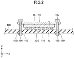
- FIG. 2 is a cross sectional view of the evaporator and its periphery of the loop heat pipe according to the first embodiment.
- four through holes 10x are formed in the evaporator 10, for example.
- the evaporator 10 and a circuit board 100 may be fixed to each other, by inserting each bolt 150 through each through hole 10x formed in the evaporator 10, and each through hole 100x formed in the circuit board 100, and securing each bolt 150 by a nut 160 from a lower surface of the circuit board 100.
- the evaporator 10, the condenser 20, the vapor pipe 30, and the liquid pipe 40 have an upper surface 1a, and a lower surface 1b on an opposite side from the upper surface 1a.
- a plan view refers to a view that is viewed from above in a direction perpendicular to the upper surface 1a.
- a heat-generating component 120 such as a CPU or the like, is mounted on the circuit board 100 via bumps 110, and an upper surface of the heat-generating component 120 makes direct contact with the lower surface 1b of the evaporator 10.
- the working fluid C inside the evaporator 10 is vaporized by the heat generated by the heat-generating component 120, to generate the vapor Cv.
- the vapor Cv generated by the evaporator 10 is guided to the condenser 20 through the vapor pipe 30, and liquefied in the condenser 20.
- the heat generated by the heat-generating component 120 is transferred to the condenser 20, thereby reducing a temperature rise of the heat-generating component 120.
- the working fluid C liquefied by the condenser 20 is guided to the evaporator 10 through the liquid pipe 40.
- a width W 1 of the vapor pipe 30 may be approximately 8 mm, for example.
- a width W 2 of the liquid pipe 40 may be approximately 6 mm, for example.
- the type of the working fluid C is not particularly limited, but in order to efficiently cool the heat-generating component 120 by the latent heat of vaporization, it is preferable to use a fluid having a high vapor pressure and a large latent heat of vaporization.
- a fluid having a high vapor pressure and a large latent heat of vaporization examples include ammonia, water, fluorocarbon, alcohol, and acetone, for example.
- the evaporator 10, the condenser 20, the vapor pipe 30, and the liquid pipe 40 may be formed by a structure in which a plurality of metal layers are laminated. As will be described later in conjunction with FIG. 4 through FIG. 7 , the evaporator 10, the condenser 20, the vapor pipe 30, and the liquid pipe 40 may be formed by a structure in which six metal layers 61 through 66 are laminated. In the evaporator 10, the condenser 20, the vapor pipe 30, and the liquid pipe 40, the metal layers 61 and 66 form the outermost metal layers, while the metal layers 62 through 65 form the intermediate metal layers.
- a pair of outer metal layers may form the outermost metal layers, and one or a plurality of metal layers may form one or a plurality of intermediate metal layers, to form a structure in which the outermost metal layers and the one or plurality of intermediate metal layers are laminated.
- the metal layers 61 through 66 are copper layers having a high thermal conductivity, for example, and the metal layers 61 through 66 are directly bonded to each other by solid phase (or solid-state) bonding or the like. Each of the metal layers 61 through 66 may have a thickness of approximately 50 ⁇ m to approximately 200 ⁇ m, for example.
- the metal layers 61 through 66 of the loop heat pipe 1 are not limited to the copper layers, and may be stainless steel layers, aluminum layers, magnesium alloy layers, or the like, for example.
- the number of metal layers that are laminated is not limited to a particular number, and may be five or less, or seven or more, for example.
- a pipe wall 90 illustrated in FIG. 3 which is formed by each of the laminated metal layers 61 through 66, is provided on both ends that are perpendicular to both a direction in which the working fluid C or the vapor Cv flows, and a laminating direction in which the metal layers 61 through 66 are laminated.
- FIG. 3 through FIG. 7 illustrate an example of the liquid pipe of the loop heat pipe according to the first embodiment.
- FIG. 3 is a plan view of a part A in FIG. 1 .
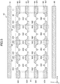
- FIG. 4 is a cross sectional view along a line IV-IV in FIG. 3
- FIG. 5 is an exploded view of FIG. 4 .
- FIG. 6 is a cross sectional view along a line VI-VI in FIG. 3
- FIG. 7 is an exploded view of FIG. 6 . Because FIG. 3 illustrates the planar shapes of a porous body and structs inside the liquid pipe 40, the illustration of the metal layer (the metal layer 61 illustrated in FIG. 4 through FIG.
- a Z-direction denotes the laminating direction of the metal layers 61 through 66
- an X-direction denotes an arbitrary direction in a plane perpendicular to the Z-direction
- a Y-direction denotes a direction perpendicular to the X-direction in this plane which is perpendicular to the Z-direction.
- a plan view refers to a view viewed from the Z-direction.
- the intermediate metal layer (the metal layers 62 through 65) of the liquid pipe 40 is provided with a pair of walls 91 forming a part of the pipe wall 90, and a porous body 60 arranged between the pair of walls 91.
- the intermediate metal layer (the metal layers 62 through 65) of the liquid pipe 40 is provided with solid structs (or support columns) 81 which penetrate the porous body 60 and bonds the metal layer 61 and the metal layer 66.
- the porous body 60 makes contact with a lower surface of the first metal layer 61 (one of the outermost metal layers) and an upper surface of the sixth metal layer 66 (the other of the outermost metal layers). No holes nor grooves are formed in the metal layer 61 and the metal layer 66.
- a plurality of bottomed holes 62x and a plurality of bottomed holes 62y are formed in the second metal layer 62 forming the porous body 60.
- the bottomed holes 62x cave in from an upper surface of the metal layer 62 to an approximate center portion along a thickness direction of the metal layer 62, and does not reach a lower surface of the metal layer 62.
- the bottomed holes 62y cave in from the lower surface of the metal layer 62 to the approximate center portion along the thickness direction of the metal layer 62, and does not reach the upper surface of the metal layer 62.
- the bottomed hole 62x and the bottomed hole 62y are alternately arranged along the X-direction in the plan view. Further, the bottomed hole 62x and the bottomed hole 62y are alternately arranged along the Y-direction in the plan view. The bottomed hole 62x and the bottomed hole 62y that are alternately arranged along the X-direction partially overlap each other in the plan view, and overlapping portions of the bottomed hole 62x and the bottomed hole 62y communicate with each other to form a pore 62z.
- the bottomed hole 62x and the bottomed holes 62y that alternately arranged along the Y-direction are formed with a predetermined spacing therebetween, and do not overlap in the plan view. Accordingly, the bottomed hole 62x and the bottomed hole 62y that are alternately arranged along the Y-direction do not form a pore.
- the bottomed holes 62x and 62y may have a circular shape with a diameter of approximately 100 ⁇ m to approximately 300 ⁇ m, for example, but may have an arbitrary shape, such as an elliptical shape, a polygonal shape, or the like.
- a depth of the bottomed holes 62x and 62y along the thickness direction may be approximately one-half the thickness of the metal layer 62, for example.
- the spacing between two mutually adjacent bottomed holes 62x may be approximately 100 ⁇ m to approximately 400 ⁇ m, for example.
- the spacing between two mutually adjacent bottomed holes 62y may be approximately 100 ⁇ m to approximately 400 ⁇ m, for example.
- Inner wall surfaces of the bottomed holes 62x and 62y may have a tapered shape which is tapered to widen from a bottom surface toward an opening of the bottomed holes 62x and 62y.
- the inner wall surfaces of the bottomed holes 62x and 62y are not limited to the tapered shape, and may have a vertical shape formed perpendicularly to the bottom surface.
- the shape of the inner wall surfaces of the bottomed holes 62x and 62y is not limited to the tapered shape or the vertical shape.
- the inner wall surfaces of the bottomed holes 62x and 62y may have a concave shape formed by a curved surface.
- Examples of the concave shape formed by the curved surface include concave shapes having cross sectional shapes that are approximately semi-circular or approximately semi-elliptical, for example.
- a width of the pore 62z along a short direction may be approximately 10 ⁇ m to approximately 50 ⁇ m, for example.
- a width of the pore 62z along a longitudinal direction may be approximately 50 ⁇ m to approximately 150 ⁇ m, for example.
- a plurality of bottomed holes 63x and a plurality of bottomed holes 63y are formed in the third metal layer 63 forming the porous body 60.
- the bottomed holes 63x cave in from an upper surface of the metal layer 63 to an approximate center portion along a thickness direction of the metal layer 63, and does not reach a lower surface of the metal layer 63.
- the bottomed holes 63y cave in from the lower surface of the metal layer 63 to the approximate center portion along the thickness direction of the metal layer 63, and does not reach the upper surface of the metal layer 63.
- a row in which only the bottomed holes 63x are arranged along the X-direction, and a row in which only the bottomed holes 63y is arranged along the X-direction, are alternately arranged along the Y-direction.
- the bottomed hole 63x and the bottomed hole 63y in two mutually adjacent rows partially overlap in the plan view, and the overlapping portions of the bottomed hole 63x and the bottomed hole 63y communicate with each other to form a pore 63z.
- center positions of the adjacent bottomed holes 63x and 63y forming the pore 63z are offset along the X-direction.
- the bottomed holes 63x and 63y forming the pore 63z are alternately arranged along an oblique direction with respect to the X-direction and the Y-direction.
- the shape of the bottomed holes 63x and 63y, the shape of the pore 63z, or the like may be similar to the shape of the bottomed holes 62x and 62y, the shape of the pore 62z, or the like.
- the bottomed hole 62y of the metal layer 62 and the bottomed hole 63x of the metal layer 63 are formed at overlapping positions in the plan view. For this reason, no pores are formed at the interface between the metal layer 62 and the metal layer 63.
- the bottomed hole 62y and the bottomed hole 63x may be offset to partially overlap each other in the plan view, thereby forming a pore at the interface between the metal layer 62 and the metal layer 63.
- a plurality of bottomed holes 64x and a plurality of bottomed holes 64y are formed in the fourth metal layer 64 forming the porous body 60.
- the bottomed hole 64x caves in from an upper surface of the fourth metal layer 64 towards an approximate center portion along the thickness direction of the fourth metal layer 64.
- the bottomed hole 64y caves in from a lower surface of the fourth metal layer 64 towards the approximate center portion along the thickness direction of the fourth metal layer 64.
- the bottomed hole 64x and the bottomed hole 64y are alternately arranged along the X-direction in the plan view.
- the bottomed hole 64x and the bottomed hole 64y are alternately arranged along the Y-direction in the plan view.
- the bottomed hole 64x and the bottomed hole 64y that are alternately arranged along the X-direction partially overlap each other in the plan view, and the overlapping portions of the bottomed holes 64x and 64y communicate with each other to form a pore 64z.
- the bottomed hole 64x and bottomed hole 64y that are alternately arranged along the Y-direction are formed with a predetermined spacing therebetween, and do not overlap in the plan view.
- the bottomed hole 64x and the bottomed hole 64y that are alternately arranged along the Y-direction do not form a pore.
- the shape of the bottomed holes 64x and 64y, the shape of the pore 64z, or the like may be similar to the shape of the bottomed holes 62x and 62y, the shape of the pore 62z, or the like.
- the bottomed hole 63y of the metal layer 63 and the bottomed hole 64x of the metal layer 64 are formed at overlapping positions in the plan view. For this reason, no pores are formed at the interface between the metal layer 63 and the metal layer 64.
- the bottomed hole 63y and the bottomed hole 64x may be offset to partially overlap each other in the plan view, thereby forming a pore at the interface between the metal layer 63 and the metal layer 64.
- a plurality of bottomed holes 65x and a plurality of bottomed holes 65y are formed in the fifth metal layer 65 forming the porous body 60.
- the bottomed hole 65x caves in from an upper surface of the fifth metal layer 65 towards an approximate center portion along the thickness direction of the fifth metal layer 65.
- the bottomed hole 65y caves in from a lower surface of the fifth metal layer 65 towards the approximate center portion along the thickness direction of the fifth metal layer 65.
- a row in which only the bottomed holes 65x are arranged along the X-direction, and a row in which only the bottomed holes 65y are arranged along the X-direction, are alternately arranged along the Y-direction.
- the bottomed hole 65x and the bottomed hole 65y in two mutually adjacent rows partially overlap each other in the plan view, and the overlapping portions of the bottomed holes 65x and 65y communicate with each other to form a pore 65z.
- center positions of the adjacent bottomed holes 65x and 65y forming the pore 65z are offset along the X-direction.
- the bottomed holes 65x and 65y forming the pore 65z are alternately arranged along an oblique direction with respect to the X-direction and the Y-direction.
- the shape of the bottomed holes 65x and 65y, the shape of the pore 65z, or the like may be similar to the shape of the bottomed holes 62x and 62y, the shape of the pore 62z, or the like.
- the bottomed hole 64y of the metal layer 64 and the bottomed hole 65x of the metal layer 65 are formed at overlapping positions in the plan view. For this reason, no pores are formed at the interface between the metal layer 64 and the metal layer 65.
- the bottomed hole 64y and the bottomed hole 65x may be offset to partially overlap each other in the plan view, thereby forming a pore at the interface between the metal layer 64 and the metal layer 65.
- the pores formed in each of the metal layers communicate with each other, and the mutually communicating pores spread three-dimensionally inside the porous body 60. For this reason, the working fluid C spreads three-dimensionally through the mutually communicating pores due to a capillary force.
- At least a portion of the bottomed holes forming the porous body 60 communicate to the passage 50 inside the condenser 20. Hence, the working fluid C can permeate into the porous body 60.
- the porous body 60 is provided inside the liquid pipe 40, and the porous body 60 extends along the liquid pipe 40 to a proximity of the evaporator 10.
- the capillary force generated in the porous body 60 guides the working fluid C in the liquid phase inside the liquid pipe 40 to the evaporator 10.
- an inlet (not illustrated) for injecting the working fluid C is formed in the liquid pipe 40, the inlet is sealed by a sealing member, and the inside of the loop heat pipe 1 is maintained airtight.
- the strut 81 is arranged at a plurality of positions inside the liquid pipe 40, for example, and to penetrate the porous body 60.
- the struts 81 extends along the liquid pipe 40, and has a rectangular planar shape that is elongated in the direction (Y-direction) in which the working fluid C flows in the plan view, for example.
- the struts 81 have a lattice-like arrangement in the plan view. In other words, a plurality of struts 81 are arranged side by side along the Y-direction, and a plurality of struts 81 are arranged side by side along the X-direction.
- a first part 621 forming a part of the wall 91, a second part 622 forming a part of the porous body 60, and a third part 623 forming a part of the strut 81, are provided in the second metal layer 62.
- the second part 622 is connected to the first part 621
- the third part 623 is connected to the second part 622.
- No holes nor grooves are formed in the first part 621 and the third part 623.
- a bottomed hole 62x, a bottomed hole 62y, and a pore 62z are formed in the second part 622.
- the first part 621, the second part 622, and the third part 623 are formed by etching a single metal layer. In other words, the first part 621, the second part 622, and the third part 623 are integrally formed.
- a first part 631 forming a part of the wall 91, a second part 632 forming a part of the porous body 60, and a third part 633 forming a part of the strut 81, are provided in the third metal layer 63.
- the second part 632 is connected to the first part 631
- the third part 633 is connected to the second part 632.
- No holes nor grooves are formed in the first part 631 and the third part 633.
- a bottomed hole 63x, a bottomed hole 63y, and a pore 63z are formed in the second part 632.
- the first part 631, the second part 632, and the third part 633 are formed by etching a single metal layer. In other words, the first part 631, the second part 632, and the third part 633 are integrally formed.
- a first part 641 forming a part of the wall 91, a second part 642 forming a part of the porous body 60, and a third part 643 forming a part of the strut 81, are formed in the fourth metal layer 64.
- the second part 642 is connected to the first part 641
- the third part 643 is connected to the second part 642.
- No holes nor grooves are formed in the first part 641 and the third part 643.
- a bottomed hole 64x, a bottomed hole 64y, and a pore 64z are formed in the second part 642.
- the first part 641, the second part 642, and the third part 643 are formed by etching a single metal layer. In other words, the first part 641, the second part 642, and the third part 643 are integrally formed.
- the fifth layer of the metal layer 65 is provided with a first part 651 forming a part of the wall 91, a second part 652 forming a part of the porous body 60, and a third part 653 forming a part of the strut 81.
- the second part 652 is connected to the first part 651
- the third part 653 is connected to the second part 652.
- No holes nor grooves are formed in the first part 651 and the third part 653.
- a bottomed hole 65x, a bottomed hole 65y, and a pore 65z are formed in the second part 652.
- the first part 651, the second part 652, and the third part 653 are formed by etching a single metal layer. In other words, the first part 651, the second part 652, and the third part 653 are integrally formed.
- the first parts 621, 631, 641, and 651 are solid portions.
- the third parts 623, 633, 643, and 653 are also solid portions.
- the first parts 621, 631, 641, and 651 overlap each other, the second parts 622, 632, 642, and 652 overlap each other, and the third parts 623, 633, 643, and 653 overlap each other.
- the metal layers 61 through 66 are directly bonded to each other by solid phase bonding or the like.
- the first parts 621, 631, 641, and 651 are bonded to each other to form the walls 91.
- the pipe wall 90 is formed from a portion of the metal layer 61, the walls 91, and a portion of the metal layer 66.
- the second parts 622, 632, 642, and 652 are bonded to each other to form the porous body 60.
- the third parts 623, 633, 643, and 653 are bonded to each other to form the solid strut 81.
- the strut 81 is bonded to the metal layer 61 and the metal layer 66.
- FIG. 8 through FIG. 10 illustrate an example of the evaporator of the loop heat pipe according to the first embodiment.
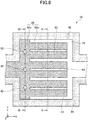
- FIG. 8 is a plan view of the evaporator.
- FIG. 9 is a cross sectional view along a line IX-IX in FIG. 8 .
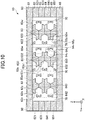
- FIG. 10 is a cross sectional view along a line X-X in FIG. 8 .
- the metal layer (the metal layer 61 illustrated in FIG. 9 and FIG. 10 ), which is one of the outermost metal layers, is not illustrated in order to illustrate the planar shapes of the porous body and the strut in the evaporator 10.
- the intermediate metal layer (the metal layers 62 through 65) of the evaporator 10 is provided with the pair of walls 91 forming a part of the pipe wall 90, and the porous body 60 between the pair of walls 91.
- the intermediate metal layer (the metal layers 62 through 65) of the evaporator 10 is also provided with solid struts 82 and 83 which penetrate the porous body 60, and bond the metal layer 61 and the metal layer 66.
- the porous body 60 in the evaporator 10 includes a connecting part 60v, and a plurality of projecting parts 60w.
- the connecting part 60v is provided on the side closest to the liquid pipe 40 along the X-direction (the side to which the liquid pipe 40 is connected to the evaporator 10), and extends along the Y-direction.
- a portion of a surface of the connecting part 60v on the side of the liquid pipe 40 makes contact with the pipe wall 90 of the evaporator 10, and the remaining portion connects to the porous body 60 inside the liquid pipe 40.
- a portion of the surface of the connecting part 60v on the side of the vapor pipe 30 is connected to the projecting parts 60w, and the remaining portion makes contact with a space 70.
- the projecting parts 60w project from the connecting part 60v toward the vapor pipe 30 in the plan view.
- the projecting parts 60w are arranged side by side at predetermined intervals along the Y-direction, and a first end of each of the projecting parts 60w on the side of the vapor pipe 30 is separated from the pipe wall 90 of the evaporator 10. Further, the first ends of the projecting parts 60w on the side of the vapor pipe 30 are not connected to each other. On the other hand, second ends of each of the projecting parts 60w on the side of the liquid pipe 40 are connected via the connecting part 60v.
- the porous body 60 inside the evaporator 10 is formed to a comb-like shape in the plan view, including the connecting part 60v and the plurality of projecting parts 60w.
- the space 70 is formed inside the evaporator 10 in a region where the porous body 60 is not provided.
- the space 70 connects to the passage 50 of the vapor pipe 30.
- the working fluid C from the liquid pipe 40 is guided toward the evaporator 10, and permeates into the porous body 60.
- the working fluid C permeated into the porous body 60 in the evaporator 10 is vaporized by the heat generated by the heat-generating component 120, thereby generating the vapor Cv which flows through the space 70 inside the evaporator 10 toward the vapor pipe 30.
- FIG. 8 illustrates an example in which the number of projecting parts 60w (the number of teeth of the comb-like shape) is three, however, the number of projecting parts 60w may be determined, as appropriate. As the contact area between the projecting parts 60w and the space 70 increases, the working fluid C is more easily evaporated, thereby reducing the pressure loss (or pressure drop).
- the strut 82 is arranged at a plurality of positions within the connecting part 60v, for example, and to penetrate the porous body 60.
- the strut 82 has an elliptical planar shape with the X-direction being the minor axis direction, and the Y-direction being the major axis direction, for example.
- a plurality of struts 82 are arranged side by side along the Y-direction.
- One strut 83 is arranged within each projecting part 60w, for example, and to penetrate the porous body 60.
- the strut 83 has a rectangular planar shape that is elongated in the X-direction, for example.
- the porous body 60 inside the evaporator 10 has a structure similar to the structure of the porous body 60 inside the liquid pipe 40.
- the struts 82 and 83 have structures similar to the structure of the strut 81.
- the first parts 621, 631, 641, and 651 of the metal layers 62 through 65 are bonded to each other to form the walls 91.
- the pipe wall 90 of evaporator 10 is formed from a portion of metal layer 61, the walls 91, and a portion of metal layer 66.
- the second parts 622, 632, 642, and 652 of the metal layers 62 through 65 are bonded to each other to form the porous body 60 inside the evaporator 10.
- the third parts 623, 633, 643, and 653 of the metal layers 62 through 65 are bonded to each other to form solid struts 82 and 83.
- the struts 82 and 83 are bonded to the metal layer 61 and the metal layer 66.
- the liquid pipe 40 is provided with the struts 81 which connect the metal layer 61 and the metal layer 66.
- the evaporator 10 is provided with the struts 82 and 83 which connect the metal layer 61 and the metal layer 66. For this reason, it is possible to reduce the deformation of the loop heat pipe 1 even if the volume of the working fluid C or the vapor Cv thereof varies due to changes in the temperature, such as the environmental temperature or the like at which the loop heat pipe 1 is used.
- the struts 81 through 83 are solid members, that is, solid members without holes, grooves, or the like, the struts 81 through 83 can strongly bond the metal layer 61 and the metal layer 66 to each other.
- the volume of the working fluid C would vary due to the phase change in the liquid working fluid C permeated into the porous body 60, thereby causing peeling (or separation) between the porous body 60 and the metal layer 61, and between the porous body 60 and the metal layer 66. If such a peeling were to occur, the working fluid C would permeate into the interface where the peeling occurs, thereby increasing the volume variation. Further, if a large volume variation were to occur, members or the like in a periphery of the loop heat pipe 1 would receive stress and become compressed, or the metal layers 61 and 66 would break near the pipe wall 90.
- the struts 81, 82, and 83 are provided so as to penetrate the porous body 60, it is possible to reduce a change in the distance between the metal layer 61 and the metal layer 66 in the periphery of the porous body 60, even if a temperature change, on the same order as the temperature described above, occurs. In other words, it is possible to reduce the deformation, such as expansion or the like of the loop heat pipe 1, and to reduce the peeling between the porous body 60 and the metal layer 61, and between the porous body 60 and the metal layer 66.
- FIG. 11A through FIG. 12B are diagrams illustrating examples of steps (or processes) for manufacturing the loop heat pipe according to the first embodiment.
- FIG. 11A through FIG. 12B illustrate cross sections corresponding to FIG. 4 .
- a process similar to the process performed with respect to the cross section corresponding to FIG. 4 is also performed with respect to the cross sections corresponding to FIG. 6 , FIG. 9 , and FIG. 10 , however, illustration thereof will be omitted.
- a metal sheet 620 formed to the planar shape illustrated in FIG. 1 is prepared. Then, a resist layer 310 is formed on an upper surface of the metal sheet 620, and a resist layer 320 is formed on a lower surface of the metal sheet 620.
- the metal sheet 620 is a member that ultimately becomes the metal layer 62, and may be formed of copper, stainless steel, aluminum, magnesium alloys, or the like, for example. The thickness of the metal sheet 620 may be approximately 50 ⁇ m to approximately 200 ⁇ m.
- a photosensitive dry film resist or the like, for example, may be used for the resist layers 310 and 320.
- the resist layer 310 is exposed and developed in a region of the metal sheet 620, where the porous body 60 is to be formed, thereby forming openings 310x which selectively expose the upper surface of the metal sheet 620.
- the resist layer 320 is exposed and developed to form openings 320x which selectively expose the lower surface of the metal sheet 620.
- the shapes and arrangements of the openings 310x and 320x are set to correspond to the shapes and arrangements of the bottomed holes 62x and 62y illustrated in FIG. 4 .
- the metal sheet 620 exposed within the opening 310x is half-etched from the upper surface of the metal sheet 620, while the metal sheet 620 exposed within the opening 320x is half-etched from the lower surface of the metal sheet 620.
- the bottomed holes 62x are formed in the upper surface of the metal sheet 620
- the bottomed holes 62y are formed in the lower surface of the metal sheet 620.
- the openings 310x and 320x are alternately arranged along the X-direction in the upper and lower surface of the metal sheet 620, and partially overlap each other in the plan view, the overlapping portions communicate with each other to form the pore 62z.
- the half-etching of the metal sheet 620 may use a ferric chloride solution, for example.
- the resist layers 310 and 320 are stripped using a stripping liquid.
- the metal layer 62 is completed.
- the metal layer 62 includes the first part 621, the second part 622, and the third part 623.
- the first part 621, the second part 622, and the third part 623 are formed by etching the single metal sheet 620.
- the second part 622 and the third part 623 are connected to each other.
- the first part 621 and the second part 622 are connected to each other via a portion which is not visible in the cross section illustrated in FIG. 11D .
- the solid metal layers 61 and 66 having no holes nor grooves are prepared.
- the metal layers 63, 64, and 65 are formed in a manner similar to the metal layer 62.
- the positions of the bottomed holes and the pores formed in the metal layers 63, 64, and 65 may be as illustrated in FIG. 4 , for example.
- the metal layers 61 through 65 are laminated in the order illustrated in FIG. 12A , and bonded to each other by the solid phase bonding by pressing and heating.
- the positions of the third parts 623 through 653 of the metal layers 62 through 65 are aligned to overlap with each other in the plan view.
- the mutually adjacent metal layers of the metal layers 61 through 65 are directly bonded to each other, thereby completing the loop heat pipe 1 having the evaporator 10, the condenser 20, the vapor pipe 30, and the liquid pipe 40, and forming the porous body 60 inside the liquid pipe 40 and the evaporator 10.
- the struts 81 through 83 are formed to penetrate the porous body 60.
- the solid phase bonding refers to a method of bonding two bonding targets together in the solid phase (or solid state) without melting the two bonding targets, by heating, softening, and further pressing the bonding targets to cause plastic deformation.
- the metal layers 61 through 66 are all made of the same material, so that the mutually adjacent metal layers can be satisfactorily bonded by the solid phase bonding.
- the mutually adjacent metal layers can be made to contact each other over a large area, thereby achieving a strong bonding.
- the third parts 623 through 653 of the metal layers 62 through 65 overlap each other in the plan view, the third parts 623 through 653 are strongly pressed between the metal layer 61 and the metal layer 66, and the struts 81 through 83 are strongly bonded to the metal layers 61 and 66.
- the porous body 60 may be provided in a portion of the condenser 20, and may be provided in a portion of the vapor pipe 30.
- FIG. 13 is the plan view illustrating an example of the liquid pipe of the loop heat pipe according to the first modification of the first embodiment.
- FIG. 13 is the plan view of a part corresponding to the part A illustrated in FIG. 1 .
- the illustration of the metal layer 61 is omitted, in order to illustrate the planar shapes of the porous body and the struts inside the liquid pipe 40.
- the positions of the adjacent struts 81 which are adjacent to each other along the X-direction are offset in the Y-direction, as illustrated in FIG. 13 .
- the structure of other parts of the loop heat pipe 1 according to the first modification is similar to that of the first embodiment.
- the struts 81 need not be provided at a plurality of positions along the Y-direction.
- a strut 81 having the same length as the liquid pipe 40 may be provided to extend from the condenser 20 to the evaporator 10.
- FIG. 14 is a cross sectional view illustrating an example of the liquid pipe of the loop heat pipe according to the second modification of the first embodiment.
- FIG. 14 corresponds to a cross sectional view along a line IV-IV in FIG. 3 .
- each of the third parts 623, 633, 643, and 653 overlap each other.
- each of the third parts 623, 633, 643, and 653 includes a region overlapping the other third parts in the plan view.
- the structure of other parts of the loop heat pipe 1 according to the second modification is similar to that of the first embodiment.
- the second modification it is possible to obtain effects similar to those obtainable in the first embodiment. Further, according to the second modification, it is possible to easily cope with various layouts of the porous body 60.
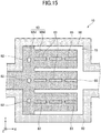
- FIG. 15 is a diagram illustrating an example of the evaporator of the loop heat pipe according to the third modification of the first embodiment.
- the illustration of the metal layer 61 is omitted, in order to illustrate the planar shapes of the porous body and the struts inside the evaporator 10.
- three struts 83 are arranged side by side along the X-direction within each projecting part 60w, as illustrated in FIG. 15 .
- the structure of other parts of the loop heat pipe 1 according to the third modification is similar to that of the first embodiment.
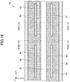
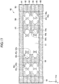
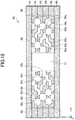
- FIG. 16 through FIG. 18 illustrate an example of the liquid pipe of the loop heat pipe according to the second embodiment.
- FIG. 16 is a plan view illustrating a part corresponding to the part A illustrated in FIG. 1 .
- FIG. 17 is a cross sectional view along a line XVII-XVII in FIG. 16 .
- FIG. 18 is a cross sectional view along a line XVIII-XVIII in FIG. 16 .
- the illustration of the metal layer 61 is omitted, in order to illustrate the planar shapes of the porous body and the struts inside the liquid pipe 40.
- the porous body 60 is provided inside the liquid pipe 40 at two locations so that the porous body 60 makes contact with the pipe walls 90 on both sides, as illustrated in FIG. 16 through FIG. 18 .
- a pair of porous bodies 60 is provided inside the liquid pipe 40.
- One of the pair of porous bodies 60 is formed integrally with one wall 91, and the other of the pair of porous bodies 60 is formed integrally with the other wall 91.
- the struts 81 are arranged to penetrate each of the pair of porous bodies 60. Predetermined struts 81 may penetrate one of the pair of porous bodies 60, and the remaining struts 81, other than the predetermined struts 81, may penetrate the other of the pair of porous bodies 60.
- the predetermined struts 81 may include one or more struts 81, for example.
- a space 51, into which the working fluid C flows, is provided between the two porous bodies 60.
- the space 51 is surrounded by mutually opposing surfaces of two porous bodies 60, the lower surface of metal layer 61, and the upper surface of metal layer 66.
- the space 51 is part of passage 50. At least a part of the bottomed holes forming the porous body 60 communicates to the space 51.
- the structure of other parts of the loop heat pipe 1 according to the second embodiment is similar to that of the first embodiment.
- the working fluid C can flow inside the space 51.
- FIG. 19 is a plan view illustrating an example of the liquid pipe of the loop heat pipe according to the modification of the second embodiment.
- FIG. 19 is a plan view illustrating a part corresponding to the part A illustrated in FIG. 1 .
- the illustration of the metal layer 61 is omitted, in order to illustrate the planar shapes of the porous body and the struts inside the liquid pipe 40.
- the porous body 60 is provided at a position separated from the pipe walls 90 on both sides, inside the liquid pipe 40, as illustrated in FIG. 19 .
- the space 51 into which the working fluid C flows, is formed between the porous body 60 and one pipe wall 90, and between the porous body 60 and the other pipe wall 90.
- the spaces 51 are surrounded by the mutually opposing surfaces of the pipe wall 90 and the porous body 60, the lower surface of metal layer 61, and the upper surface of metal layer 66.
- the spaces 51 are parts of passage 50. At least a part of the bottomed holes forming the porous body 60 communicates to the spaces 51.
- the structure of other parts of the loop heat pipe 1 according to the modification of the second embodiment is similar to that of the second embodiment.
Landscapes
- Engineering & Computer Science (AREA)
- Physics & Mathematics (AREA)
- Thermal Sciences (AREA)
- Life Sciences & Earth Sciences (AREA)
- Sustainable Development (AREA)
- Mechanical Engineering (AREA)
- General Engineering & Computer Science (AREA)
- Microelectronics & Electronic Packaging (AREA)
- Cooling Or The Like Of Semiconductors Or Solid State Devices (AREA)
Abstract
Description
- Certain aspects of the embodiments discussed herein are related to loop heat pipes, and methods for manufacturing the loop heat pipe.
- The heat pipe is known as a device for cooling a heat-generating component, such as a Central Processing Unit (CPU) or the like, provided in electronic devices. The heat pipe utilizes a phase change of a working fluid to transfer heat.
- A loop heat pipe is an example of the heat pipe, and includes an evaporator that vaporizes the working fluid by the heat of the heat-generating component, and a condenser that liquefies the vaporized working fluid. The evaporator and the condenser are connected by a loop shaped passage that is formed by a liquid pipe and a vapor pipe. In the loop heat pipe, the working fluid flows through the loop shaped passage in one direction.
- In addition, a porous body is provided inside the evaporator and the liquid pipe of the loop heat pipe, and the working fluid inside the liquid pipe is guided to the evaporator due to a capillary force generated in the porous body, to restrict the backflow of vapor from the evaporator to the liquid pipe. A large number of pores are formed in the porous body. Each pore is formed by partially communicating a bottomed hole formed in one side of a metal layer, and a bottomed hole formed in the other side of the metal layer, as described in Japanese Laid-Open Patent Publications No.
2018-036012 2019-135434 6291000 6400240 - Other heat pipes are described in Japanese Laid-Open Patent Publication No.
H11-183067 - However, the conventional loop heat pipes may become deformed due to variations in the volume of the working fluid caused by temperature changes.
- Accordingly, it is an object in one aspect of the embodiments to provide a loop heat pipe, and a method for manufacturing the loop heat pipe, which can reduce the deformation of the loop heat pipe due to variations in the volume of the working fluid.
- According to one aspect of the embodiments, a loop heat pipe includes a pair of outermost metal layers; an intermediate metal layer provided between the pair of outermost metal layers; an evaporator configured to vaporize a working fluid to generate vapor; a condenser configured to liquefy the vapor of the working fluid; a liquid pipe connecting the evaporator and the condenser; and a vapor pipe connecting the evaporator and the condenser, and forming a loop shaped passage together with the liquid pipe, wherein the intermediate metal layer includes a pair of walls forming a part of a pipe wall of the evaporator, the condenser, the liquid pipe, and the vapor pipe, a porous body provided between the pair of walls, a first strut penetrating the porous body and bonding the pair of outermost metal layers to each other, and one or a plurality of metal layers, wherein each of the one or plurality of metal layers of the intermediate metal layer includes a first part forming at least a part of the pair of walls, a second part connected to the first part, and forming at least a part of the porous body, and a third part connected to the second part, and forming at least a part of the first strut.
- According to another aspect of the embodiments, a method for manufacturing a loop heat pipe which includes a pair of outermost metal layers, an intermediate metal layer provided between the pair of outermost metal layers, an evaporator configured to vaporize a working fluid to generate vapor, a condenser configured to liquefy the vapor of the working fluid, and a liquid pipe and a vapor pipe, connecting the evaporator and the condenser, and forming a loop shaped passage, the method including the steps of forming the intermediate metal layer, including a pair of walls forming a part of a pipe wall of the evaporator, the condenser, the liquid pipe, and the vapor pipe, a porous body provided between the pair of walls, and a strut penetrating the porous body and bonding the pair of outermost metal layers to each other, from one or a plurality of metal layers, wherein the forming the intermediate metal layer etches the one or plurality of metal layers to form a first part forming at least a part of the pair of walls, a second part connected to the first part, and forming at least a part of the porous body, and a third part connected to the second part, and forming at least a part of the strut.
- The object and advantages of the embodiments will be realized and attained by means of the elements and combinations particularly pointed out in the claims.
- It is to be understood that both the foregoing general description and the following detailed description are exemplary and explanatory and not restrictive of the invention, as claimed.
-
-
FIG. 1 is a plan view schematically illustrating an example of a loop heat pipe according to a first embodiment. -
FIG. 2 is a cross sectional view of an evaporator and its periphery of the loop heat pipe according to the first embodiment. -
FIG. 3 is a plan view illustrating an example of a liquid pipe of the loop heat pipe according to the first embodiment. -
FIG. 4 is a cross sectional view (part 1) illustrating the example of the liquid pipe of the loop heat pipe according to the first embodiment. -
FIG. 5 is an exploded view ofFIG. 4 . -
FIG. 6 is a cross sectional view (part 2) illustrating the example of the liquid pipe of the loop heat pipe according to the first embodiment. -
FIG. 7 is an exploded view ofFIG. 6 . -
FIG. 8 is a plan view illustrating an example of an evaporator of the loop heat pipe according to the first embodiment. -
FIG. 9 is a cross sectional view (part 1) illustrating the example of the evaporator of the loop heat pipe according to the first embodiment. -
FIG. 10 is a cross sectional view (part 2) illustrating the example of the evaporator of the loop heat pipe according to the first embodiment. -
FIG. 11A, FIG. 11B, FIG. 11C, and FIG. 11D are diagrams (part 1) illustrating examples of steps for manufacturing the loop heat pipe according to the first embodiment. -
FIG. 12A and FIG. 12B are diagrams (part 2) illustrating examples of steps for manufacturing the loop heat pipe according to the first embodiment. -
FIG. 13 is a plan view illustrating an example of the liquid pipe of the loop heat pipe according to a first modification of the first embodiment. -
FIG. 14 is a plan view illustrating an example of the liquid pipe of the loop heat pipe according to a second modification of the first embodiment. -
FIG. 15 is a plan view illustrating an example of the liquid pipe of the loop heat pipe according to a third modification of the first embodiment. -
FIG. 16 is a plan view illustrating an example of the liquid pipe of the loop heat pipe according to a second embodiment. -
FIG. 17 is a cross sectional view (part 1) illustrating the example of the liquid pipe of the loop heat pipe according to the second embodiment. -
FIG. 18 is a cross sectional view (part 2) illustrating the example of the liquid pipe of the loop heat pipe according to the second embodiment. -
FIG. 19 is a plan view illustrating an example of the liquid pipe of the loop heat pipe according to a modification of the second embodiment. - Preferred embodiments of the present invention will be described with reference to the accompanying drawings. In the drawings, those parts that are the same are designated by the same reference numerals, and a repeated description of the same parts may be omitted.
- A description will now be given of embodiments of a loop heat pipe and a method for manufacturing the loop heat pipe according to the present invention.
- First, a structure of the loop heat pipe according to a first embodiment will be described.
FIG. 1 is a plan view schematically illustrating an example of the loop heat pipe according to the first embodiment. - As illustrated in
FIG. 1 , aloop heat pipe 1 includes anevaporator 10, acondenser 20, avapor pipe 30, and aliquid pipe 40. Theloop heat pipe 1 may be accommodated in a mobileelectronic device 2, such as a smartphone, a tablet terminal, or the like, for example. - In the
loop heat pipe 1, theevaporator 10 has a function to vaporize a working fluid C to generate vapor Cv. Thecondenser 20 has a function to liquefy the vapor Cv of the working fluid C. Theevaporator 10 and thecondenser 20 are connected via thevapor pipe 30 and theliquid pipe 40, and thevapor pipe 30 and theliquid pipe 40 form a loop shaped passage (or fluid channel) 50 in which the working fluid C or the vapor Cv flows. -
FIG. 2 is a cross sectional view of the evaporator and its periphery of the loop heat pipe according to the first embodiment. As illustrated inFIG. 1 andFIG. 2 , four throughholes 10x are formed in theevaporator 10, for example. Theevaporator 10 and acircuit board 100 may be fixed to each other, by inserting eachbolt 150 through each throughhole 10x formed in theevaporator 10, and each throughhole 100x formed in thecircuit board 100, and securing eachbolt 150 by anut 160 from a lower surface of thecircuit board 100. Theevaporator 10, thecondenser 20, thevapor pipe 30, and theliquid pipe 40 have anupper surface 1a, and alower surface 1b on an opposite side from theupper surface 1a. In the present disclosure, a plan view refers to a view that is viewed from above in a direction perpendicular to theupper surface 1a. - For example, a heat-
generating component 120, such as a CPU or the like, is mounted on thecircuit board 100 viabumps 110, and an upper surface of the heat-generating component 120 makes direct contact with thelower surface 1b of theevaporator 10. The working fluid C inside theevaporator 10 is vaporized by the heat generated by the heat-generatingcomponent 120, to generate the vapor Cv. - As illustrated in
FIG. 1 , the vapor Cv generated by theevaporator 10 is guided to thecondenser 20 through thevapor pipe 30, and liquefied in thecondenser 20. Hence, the heat generated by the heat-generatingcomponent 120 is transferred to thecondenser 20, thereby reducing a temperature rise of the heat-generatingcomponent 120. The working fluid C liquefied by thecondenser 20 is guided to theevaporator 10 through theliquid pipe 40. A width W1 of thevapor pipe 30 may be approximately 8 mm, for example. In addition, a width W2 of theliquid pipe 40 may be approximately 6 mm, for example. - The type of the working fluid C is not particularly limited, but in order to efficiently cool the heat-generating
component 120 by the latent heat of vaporization, it is preferable to use a fluid having a high vapor pressure and a large latent heat of vaporization. Examples of such a fluid include ammonia, water, fluorocarbon, alcohol, and acetone, for example. - The
evaporator 10, thecondenser 20, thevapor pipe 30, and theliquid pipe 40 may be formed by a structure in which a plurality of metal layers are laminated. As will be described later in conjunction withFIG. 4 through FIG. 7 , theevaporator 10, thecondenser 20, thevapor pipe 30, and theliquid pipe 40 may be formed by a structure in which sixmetal layers 61 through 66 are laminated. In theevaporator 10, thecondenser 20, thevapor pipe 30, and theliquid pipe 40, the metal layers 61 and 66 form the outermost metal layers, while the metal layers 62 through 65 form the intermediate metal layers. However, in theevaporator 10, thecondenser 20, thevapor pipe 30, and theliquid pipe 40, a pair of outer metal layers may form the outermost metal layers, and one or a plurality of metal layers may form one or a plurality of intermediate metal layers, to form a structure in which the outermost metal layers and the one or plurality of intermediate metal layers are laminated. - The metal layers 61 through 66 are copper layers having a high thermal conductivity, for example, and the metal layers 61 through 66 are directly bonded to each other by solid phase (or solid-state) bonding or the like. Each of the metal layers 61 through 66 may have a thickness of approximately 50 µm to approximately 200 µm, for example. Of course, the metal layers 61 through 66 of the
loop heat pipe 1 are not limited to the copper layers, and may be stainless steel layers, aluminum layers, magnesium alloy layers, or the like, for example. In addition, the number of metal layers that are laminated is not limited to a particular number, and may be five or less, or seven or more, for example. - In each of the
evaporator 10, thecondenser 20, thevapor pipe 30, and theliquid pipe 40, apipe wall 90 illustrated inFIG. 3 , which is formed by each of the laminated metal layers 61 through 66, is provided on both ends that are perpendicular to both a direction in which the working fluid C or the vapor Cv flows, and a laminating direction in which the metal layers 61 through 66 are laminated. - Next, the structure of the
liquid pipe 40 will be described.FIG. 3 through FIG. 7 illustrate an example of the liquid pipe of the loop heat pipe according to the first embodiment.FIG. 3 is a plan view of a part A inFIG. 1 .FIG. 4 is a cross sectional view along a line IV-IV inFIG. 3 , andFIG. 5 is an exploded view ofFIG. 4 .FIG. 6 is a cross sectional view along a line VI-VI inFIG. 3 , andFIG. 7 is an exploded view ofFIG. 6 . BecauseFIG. 3 illustrates the planar shapes of a porous body and structs inside theliquid pipe 40, the illustration of the metal layer (themetal layer 61 illustrated inFIG. 4 through FIG. 7 ) that is one of the outermost metal layers is omitted inFIG. 3 . InFIG. 3 through FIG. 7 , a Z-direction denotes the laminating direction of the metal layers 61 through 66, and an X-direction denotes an arbitrary direction in a plane perpendicular to the Z-direction, and a Y-direction denotes a direction perpendicular to the X-direction in this plane which is perpendicular to the Z-direction. The same applies to other subsequent figures. In the present disclosure, a plan view refers to a view viewed from the Z-direction. - As illustrated in
FIG. 3 through FIG. 7 , the intermediate metal layer (the metal layers 62 through 65) of theliquid pipe 40 is provided with a pair ofwalls 91 forming a part of thepipe wall 90, and aporous body 60 arranged between the pair ofwalls 91. In addition, the intermediate metal layer (the metal layers 62 through 65) of theliquid pipe 40 is provided with solid structs (or support columns) 81 which penetrate theporous body 60 and bonds themetal layer 61 and themetal layer 66. - The
porous body 60 makes contact with a lower surface of the first metal layer 61 (one of the outermost metal layers) and an upper surface of the sixth metal layer 66 (the other of the outermost metal layers). No holes nor grooves are formed in themetal layer 61 and themetal layer 66. On the other hand, as illustrated inFIG. 4 through FIG. 7 , a plurality of bottomedholes 62x and a plurality of bottomedholes 62y are formed in thesecond metal layer 62 forming theporous body 60. The bottomedholes 62x cave in from an upper surface of themetal layer 62 to an approximate center portion along a thickness direction of themetal layer 62, and does not reach a lower surface of themetal layer 62. The bottomedholes 62y cave in from the lower surface of themetal layer 62 to the approximate center portion along the thickness direction of themetal layer 62, and does not reach the upper surface of themetal layer 62. - The bottomed
hole 62x and the bottomedhole 62y are alternately arranged along the X-direction in the plan view. Further, the bottomedhole 62x and the bottomedhole 62y are alternately arranged along the Y-direction in the plan view. The bottomedhole 62x and the bottomedhole 62y that are alternately arranged along the X-direction partially overlap each other in the plan view, and overlapping portions of the bottomedhole 62x and the bottomedhole 62y communicate with each other to form apore 62z. The bottomedhole 62x and the bottomedholes 62y that alternately arranged along the Y-direction are formed with a predetermined spacing therebetween, and do not overlap in the plan view. Accordingly, the bottomedhole 62x and the bottomedhole 62y that are alternately arranged along the Y-direction do not form a pore. - The bottomed
holes holes metal layer 62, for example. The spacing between two mutually adjacent bottomedholes 62x may be approximately 100 µm to approximately 400 µm, for example. The spacing between two mutually adjacent bottomedholes 62y may be approximately 100 µm to approximately 400 µm, for example. - Inner wall surfaces of the bottomed
holes holes holes holes holes pore 62z along a short direction may be approximately 10 µm to approximately 50 µm, for example. In addition, a width of thepore 62z along a longitudinal direction may be approximately 50 µm to approximately 150 µm, for example. - As illustrated in
FIG. 4 through FIG. 7 , a plurality of bottomedholes 63x and a plurality of bottomedholes 63y are formed in thethird metal layer 63 forming theporous body 60. The bottomedholes 63x cave in from an upper surface of themetal layer 63 to an approximate center portion along a thickness direction of themetal layer 63, and does not reach a lower surface of themetal layer 63. The bottomedholes 63y cave in from the lower surface of themetal layer 63 to the approximate center portion along the thickness direction of themetal layer 63, and does not reach the upper surface of themetal layer 63. - In the
metal layer 63, a row in which only the bottomedholes 63x are arranged along the X-direction, and a row in which only the bottomedholes 63y is arranged along the X-direction, are alternately arranged along the Y-direction. In the rows that are alternately arranged along the Y-direction, the bottomedhole 63x and the bottomedhole 63y in two mutually adjacent rows partially overlap in the plan view, and the overlapping portions of the bottomedhole 63x and the bottomedhole 63y communicate with each other to form apore 63z. - However, center positions of the adjacent bottomed
holes pore 63z are offset along the X-direction. In other words, the bottomedholes pore 63z are alternately arranged along an oblique direction with respect to the X-direction and the Y-direction. The shape of the bottomedholes pore 63z, or the like may be similar to the shape of the bottomedholes pore 62z, or the like. - The bottomed
hole 62y of themetal layer 62 and the bottomedhole 63x of themetal layer 63 are formed at overlapping positions in the plan view. For this reason, no pores are formed at the interface between themetal layer 62 and themetal layer 63. The bottomedhole 62y and the bottomedhole 63x may be offset to partially overlap each other in the plan view, thereby forming a pore at the interface between themetal layer 62 and themetal layer 63. - As illustrated in
FIG. 4 through FIG. 7 , a plurality of bottomedholes 64x and a plurality of bottomedholes 64y are formed in thefourth metal layer 64 forming theporous body 60. The bottomedhole 64x caves in from an upper surface of thefourth metal layer 64 towards an approximate center portion along the thickness direction of thefourth metal layer 64. The bottomedhole 64y caves in from a lower surface of thefourth metal layer 64 towards the approximate center portion along the thickness direction of thefourth metal layer 64. - The bottomed
hole 64x and the bottomedhole 64y are alternately arranged along the X-direction in the plan view. In addition, the bottomedhole 64x and the bottomedhole 64y are alternately arranged along the Y-direction in the plan view. The bottomedhole 64x and the bottomedhole 64y that are alternately arranged along the X-direction partially overlap each other in the plan view, and the overlapping portions of the bottomedholes pore 64z. The bottomedhole 64x and bottomedhole 64y that are alternately arranged along the Y-direction are formed with a predetermined spacing therebetween, and do not overlap in the plan view. Accordingly, the bottomedhole 64x and the bottomedhole 64y that are alternately arranged along the Y-direction do not form a pore. The shape of the bottomedholes pore 64z, or the like may be similar to the shape of the bottomedholes pore 62z, or the like. - The bottomed
hole 63y of themetal layer 63 and the bottomedhole 64x of themetal layer 64 are formed at overlapping positions in the plan view. For this reason, no pores are formed at the interface between themetal layer 63 and themetal layer 64. The bottomedhole 63y and the bottomedhole 64x may be offset to partially overlap each other in the plan view, thereby forming a pore at the interface between themetal layer 63 and themetal layer 64. - As illustrated in
FIG. 4 through FIG. 7 , a plurality of bottomedholes 65x and a plurality of bottomedholes 65y are formed in thefifth metal layer 65 forming theporous body 60. The bottomedhole 65x caves in from an upper surface of thefifth metal layer 65 towards an approximate center portion along the thickness direction of thefifth metal layer 65. The bottomedhole 65y caves in from a lower surface of thefifth metal layer 65 towards the approximate center portion along the thickness direction of thefifth metal layer 65. - In the
metal layer 65, a row in which only the bottomedholes 65x are arranged along the X-direction, and a row in which only the bottomedholes 65y are arranged along the X-direction, are alternately arranged along the Y-direction. In the rows that are alternately arranged along the Y-direction, the bottomedhole 65x and the bottomedhole 65y in two mutually adjacent rows partially overlap each other in the plan view, and the overlapping portions of the bottomedholes pore 65z. - However, center positions of the adjacent bottomed
holes pore 65z are offset along the X-direction. In other words, the bottomedholes pore 65z are alternately arranged along an oblique direction with respect to the X-direction and the Y-direction. The shape of the bottomedholes pore 65z, or the like may be similar to the shape of the bottomedholes pore 62z, or the like. - The bottomed
hole 64y of themetal layer 64 and the bottomedhole 65x of themetal layer 65 are formed at overlapping positions in the plan view. For this reason, no pores are formed at the interface between themetal layer 64 and themetal layer 65. The bottomedhole 64y and the bottomedhole 65x may be offset to partially overlap each other in the plan view, thereby forming a pore at the interface between themetal layer 64 and themetal layer 65. - The pores formed in each of the metal layers communicate with each other, and the mutually communicating pores spread three-dimensionally inside the
porous body 60. For this reason, the working fluid C spreads three-dimensionally through the mutually communicating pores due to a capillary force. - At least a portion of the bottomed holes forming the
porous body 60 communicate to thepassage 50 inside thecondenser 20. Hence, the working fluid C can permeate into theporous body 60. - Accordingly, the
porous body 60 is provided inside theliquid pipe 40, and theporous body 60 extends along theliquid pipe 40 to a proximity of theevaporator 10. Thus, the capillary force generated in theporous body 60 guides the working fluid C in the liquid phase inside theliquid pipe 40 to theevaporator 10. - As a result, a backflow of the vapor Cv into the
liquid pipe 40 due to a heat leak or the like from theevaporator 10, can be pushed back due to the capillary force from theporous body 60 acting on the working fluid C in the liquid phase, thereby preventing the backflow of the vapor Cv. - Although an inlet (not illustrated) for injecting the working fluid C is formed in the
liquid pipe 40, the inlet is sealed by a sealing member, and the inside of theloop heat pipe 1 is maintained airtight. - The
strut 81 is arranged at a plurality of positions inside theliquid pipe 40, for example, and to penetrate theporous body 60. The struts 81 extends along theliquid pipe 40, and has a rectangular planar shape that is elongated in the direction (Y-direction) in which the working fluid C flows in the plan view, for example. For example, thestruts 81 have a lattice-like arrangement in the plan view. In other words, a plurality ofstruts 81 are arranged side by side along the Y-direction, and a plurality ofstruts 81 are arranged side by side along the X-direction. - As illustrated in
FIG. 4 through FIG. 7 , afirst part 621 forming a part of thewall 91, asecond part 622 forming a part of theporous body 60, and athird part 623 forming a part of thestrut 81, are provided in thesecond metal layer 62. Thesecond part 622 is connected to thefirst part 621, and thethird part 623 is connected to thesecond part 622. No holes nor grooves are formed in thefirst part 621 and thethird part 623. A bottomedhole 62x, a bottomedhole 62y, and apore 62z are formed in thesecond part 622. As will be described later, thefirst part 621, thesecond part 622, and thethird part 623 are formed by etching a single metal layer. In other words, thefirst part 621, thesecond part 622, and thethird part 623 are integrally formed. - As illustrated in
FIG. 4 through FIG. 7 , afirst part 631 forming a part of thewall 91, asecond part 632 forming a part of theporous body 60, and athird part 633 forming a part of thestrut 81, are provided in thethird metal layer 63. Thesecond part 632 is connected to thefirst part 631, and thethird part 633 is connected to thesecond part 632. No holes nor grooves are formed in thefirst part 631 and thethird part 633. A bottomedhole 63x, a bottomedhole 63y, and apore 63z are formed in thesecond part 632. As will be described later, thefirst part 631, thesecond part 632, and thethird part 633 are formed by etching a single metal layer. In other words, thefirst part 631, thesecond part 632, and thethird part 633 are integrally formed. - As illustrated in
FIG. 4 through FIG. 7 , afirst part 641 forming a part of thewall 91, asecond part 642 forming a part of theporous body 60, and athird part 643 forming a part of thestrut 81, are formed in thefourth metal layer 64. Thesecond part 642 is connected to thefirst part 641, and thethird part 643 is connected to thesecond part 642. No holes nor grooves are formed in thefirst part 641 and thethird part 643. A bottomedhole 64x, a bottomedhole 64y, and apore 64z are formed in thesecond part 642. As will be described later, thefirst part 641, thesecond part 642, and thethird part 643 are formed by etching a single metal layer. In other words, thefirst part 641, thesecond part 642, and thethird part 643 are integrally formed. - As illustrated in
FIG. 4 through FIG. 7 , the fifth layer of themetal layer 65 is provided with afirst part 651 forming a part of thewall 91, asecond part 652 forming a part of theporous body 60, and athird part 653 forming a part of thestrut 81. Thesecond part 652 is connected to thefirst part 651, and thethird part 653 is connected to thesecond part 652. No holes nor grooves are formed in thefirst part 651 and thethird part 653. A bottomedhole 65x, a bottomedhole 65y, and apore 65z are formed in thesecond part 652. As will be described later, thefirst part 651, thesecond part 652, and thethird part 653 are formed by etching a single metal layer. In other words, thefirst part 651, thesecond part 652, and thethird part 653 are integrally formed. - The
first parts third parts first parts second parts third parts first parts walls 91. Thepipe wall 90 is formed from a portion of themetal layer 61, thewalls 91, and a portion of themetal layer 66. Thesecond parts porous body 60. Thethird parts solid strut 81. Thestrut 81 is bonded to themetal layer 61 and themetal layer 66. - Next, the structure of
evaporator 10 will be described.FIG. 8 through FIG. 10 illustrate an example of the evaporator of the loop heat pipe according to the first embodiment.FIG. 8 is a plan view of the evaporator.FIG. 9 is a cross sectional view along a line IX-IX inFIG. 8 .FIG. 10 is a cross sectional view along a line X-X inFIG. 8 . InFIG. 8 , the metal layer (themetal layer 61 illustrated inFIG. 9 andFIG. 10 ), which is one of the outermost metal layers, is not illustrated in order to illustrate the planar shapes of the porous body and the strut in theevaporator 10. - As illustrated in
FIG. 8 through FIG. 10 , the intermediate metal layer (the metal layers 62 through 65) of theevaporator 10 is provided with the pair ofwalls 91 forming a part of thepipe wall 90, and theporous body 60 between the pair ofwalls 91. The intermediate metal layer (the metal layers 62 through 65) of theevaporator 10 is also provided withsolid struts porous body 60, and bond themetal layer 61 and themetal layer 66. - As illustrated in
FIG. 8 , theporous body 60 in theevaporator 10 includes a connectingpart 60v, and a plurality of projectingparts 60w. - In the plan view, the connecting
part 60v is provided on the side closest to theliquid pipe 40 along the X-direction (the side to which theliquid pipe 40 is connected to the evaporator 10), and extends along the Y-direction. A portion of a surface of the connectingpart 60v on the side of theliquid pipe 40 makes contact with thepipe wall 90 of theevaporator 10, and the remaining portion connects to theporous body 60 inside theliquid pipe 40. A portion of the surface of the connectingpart 60v on the side of thevapor pipe 30 is connected to the projectingparts 60w, and the remaining portion makes contact with aspace 70. - The projecting
parts 60w project from the connectingpart 60v toward thevapor pipe 30 in the plan view. - The projecting
parts 60w are arranged side by side at predetermined intervals along the Y-direction, and a first end of each of the projectingparts 60w on the side of thevapor pipe 30 is separated from thepipe wall 90 of theevaporator 10. Further, the first ends of the projectingparts 60w on the side of thevapor pipe 30 are not connected to each other. On the other hand, second ends of each of the projectingparts 60w on the side of theliquid pipe 40 are connected via the connectingpart 60v. In other words, theporous body 60 inside theevaporator 10 is formed to a comb-like shape in the plan view, including the connectingpart 60v and the plurality of projectingparts 60w. - The
space 70 is formed inside theevaporator 10 in a region where theporous body 60 is not provided. Thespace 70 connects to thepassage 50 of thevapor pipe 30. - The working fluid C from the
liquid pipe 40 is guided toward theevaporator 10, and permeates into theporous body 60. The working fluid C permeated into theporous body 60 in theevaporator 10 is vaporized by the heat generated by the heat-generatingcomponent 120, thereby generating the vapor Cv which flows through thespace 70 inside theevaporator 10 toward thevapor pipe 30.FIG. 8 illustrates an example in which the number of projectingparts 60w (the number of teeth of the comb-like shape) is three, however, the number of projectingparts 60w may be determined, as appropriate. As the contact area between the projectingparts 60w and thespace 70 increases, the working fluid C is more easily evaporated, thereby reducing the pressure loss (or pressure drop). - The
strut 82 is arranged at a plurality of positions within the connectingpart 60v, for example, and to penetrate theporous body 60. Thestrut 82 has an elliptical planar shape with the X-direction being the minor axis direction, and the Y-direction being the major axis direction, for example. For example, a plurality ofstruts 82 are arranged side by side along the Y-direction. - One
strut 83 is arranged within each projectingpart 60w, for example, and to penetrate theporous body 60. Thestrut 83 has a rectangular planar shape that is elongated in the X-direction, for example. - The
porous body 60 inside theevaporator 10 has a structure similar to the structure of theporous body 60 inside theliquid pipe 40. Thestruts strut 81. In other words, thefirst parts walls 91. Thepipe wall 90 ofevaporator 10 is formed from a portion ofmetal layer 61, thewalls 91, and a portion ofmetal layer 66. Thesecond parts porous body 60 inside theevaporator 10. Thethird parts solid struts struts metal layer 61 and themetal layer 66. - Accordingly, the
liquid pipe 40 is provided with thestruts 81 which connect themetal layer 61 and themetal layer 66. In addition, theevaporator 10 is provided with thestruts metal layer 61 and themetal layer 66. For this reason, it is possible to reduce the deformation of theloop heat pipe 1 even if the volume of the working fluid C or the vapor Cv thereof varies due to changes in the temperature, such as the environmental temperature or the like at which theloop heat pipe 1 is used. Because thestruts 81 through 83 are solid members, that is, solid members without holes, grooves, or the like, thestruts 81 through 83 can strongly bond themetal layer 61 and themetal layer 66 to each other. - If the
struts porous body 60, thereby causing peeling (or separation) between theporous body 60 and themetal layer 61, and between theporous body 60 and themetal layer 66. If such a peeling were to occur, the working fluid C would permeate into the interface where the peeling occurs, thereby increasing the volume variation. Further, if a large volume variation were to occur, members or the like in a periphery of theloop heat pipe 1 would receive stress and become compressed, or the metal layers 61 and 66 would break near thepipe wall 90. - On the other hand, in this embodiment, because the
struts porous body 60, it is possible to reduce a change in the distance between themetal layer 61 and themetal layer 66 in the periphery of theporous body 60, even if a temperature change, on the same order as the temperature described above, occurs. In other words, it is possible to reduce the deformation, such as expansion or the like of theloop heat pipe 1, and to reduce the peeling between theporous body 60 and themetal layer 61, and between theporous body 60 and themetal layer 66. - Next, a method for manufacturing the loop heat pipe according to the first embodiment will be described, by focusing on a method for manufacturing the porous body.
FIG. 11A through FIG. 12B are diagrams illustrating examples of steps (or processes) for manufacturing the loop heat pipe according to the first embodiment.FIG. 11A through FIG. 12B illustrate cross sections corresponding toFIG. 4 . InFIG. 11A through FIG. 12B , a process similar to the process performed with respect to the cross section corresponding toFIG. 4 is also performed with respect to the cross sections corresponding toFIG. 6 ,FIG. 9 , andFIG. 10 , however, illustration thereof will be omitted. - First, in the process illustrated in
FIG. 11A , ametal sheet 620 formed to the planar shape illustrated inFIG. 1 is prepared. Then, a resistlayer 310 is formed on an upper surface of themetal sheet 620, and a resistlayer 320 is formed on a lower surface of themetal sheet 620. Themetal sheet 620 is a member that ultimately becomes themetal layer 62, and may be formed of copper, stainless steel, aluminum, magnesium alloys, or the like, for example. The thickness of themetal sheet 620 may be approximately 50 µm to approximately 200 µm. A photosensitive dry film resist or the like, for example, may be used for the resistlayers - Next, in the process illustrated in
FIG. 11B , the resistlayer 310 is exposed and developed in a region of themetal sheet 620, where theporous body 60 is to be formed, thereby formingopenings 310x which selectively expose the upper surface of themetal sheet 620. In addition, the resistlayer 320 is exposed and developed to formopenings 320x which selectively expose the lower surface of themetal sheet 620. The shapes and arrangements of theopenings holes FIG. 4 . - Next, in the process illustrated in
FIG. 11C , themetal sheet 620 exposed within theopening 310x is half-etched from the upper surface of themetal sheet 620, while themetal sheet 620 exposed within theopening 320x is half-etched from the lower surface of themetal sheet 620. Hence, the bottomedholes 62x are formed in the upper surface of themetal sheet 620, and the bottomedholes 62y are formed in the lower surface of themetal sheet 620. In addition, because theopenings metal sheet 620, and partially overlap each other in the plan view, the overlapping portions communicate with each other to form thepore 62z. The half-etching of themetal sheet 620 may use a ferric chloride solution, for example. - Next, in the process illustrated in
FIG. 11D , the resistlayers metal layer 62 is completed. Themetal layer 62 includes thefirst part 621, thesecond part 622, and thethird part 623. Hence, thefirst part 621, thesecond part 622, and thethird part 623 are formed by etching thesingle metal sheet 620. As illustrated inFIG. 11D , thesecond part 622 and thethird part 623 are connected to each other. Further, thefirst part 621 and thesecond part 622 are connected to each other via a portion which is not visible in the cross section illustrated inFIG. 11D . - Next, in the process illustrated in
FIG. 12A , thesolid metal layers metal layer 62. The positions of the bottomed holes and the pores formed in the metal layers 63, 64, and 65 may be as illustrated inFIG. 4 , for example. - Next, in the process illustrated in
FIG. 12B , the metal layers 61 through 65 are laminated in the order illustrated inFIG. 12A , and bonded to each other by the solid phase bonding by pressing and heating. In this state, the positions of thethird parts 623 through 653 of the metal layers 62 through 65 are aligned to overlap with each other in the plan view. Accordingly, the mutually adjacent metal layers of the metal layers 61 through 65 are directly bonded to each other, thereby completing theloop heat pipe 1 having theevaporator 10, thecondenser 20, thevapor pipe 30, and theliquid pipe 40, and forming theporous body 60 inside theliquid pipe 40 and theevaporator 10. Moreover, thestruts 81 through 83 are formed to penetrate theporous body 60. After the inside of theliquid pipe 40 is evacuated using a vacuum pump or the like, the working fluid C is injected into theliquid pipe 40 through the inlet (not illustrated), and the inlet is sealed thereafter. - The solid phase bonding refers to a method of bonding two bonding targets together in the solid phase (or solid state) without melting the two bonding targets, by heating, softening, and further pressing the bonding targets to cause plastic deformation. Preferably, the metal layers 61 through 66 are all made of the same material, so that the mutually adjacent metal layers can be satisfactorily bonded by the solid phase bonding.
- Accordingly, by employing the structure in which the pores are formed in each metal layer by partially communicating the bottomed holes in both the upper and lower surfaces of each metal layer, it is possible to form the pores having a constant size in the metal layer. For this reason, it is possible to prevent the capillary force generated by the pores from deteriorating, that is, decreasing, which would otherwise occur if the size of the pores were inconsistent. As a result, it is possible to stably obtain the effect of reducing the backflow of the vapor Cv from the
evaporator 10 to theliquid pipe 40. - In addition, by employing a structure in which the adjacent bottomed holes overlap each other in their entirety at the portion where the mutually adjacent metal layers are laminated, the mutually adjacent metal layers can be made to contact each other over a large area, thereby achieving a strong bonding. For example, because the
third parts 623 through 653 of the metal layers 62 through 65 overlap each other in the plan view, thethird parts 623 through 653 are strongly pressed between themetal layer 61 and themetal layer 66, and thestruts 81 through 83 are strongly bonded to the metal layers 61 and 66. - The
porous body 60 may be provided in a portion of thecondenser 20, and may be provided in a portion of thevapor pipe 30. - In a first modification of the first embodiment, the arrangement of the
struts 81 is different from that of the first embodiment. In the first modification of the first embodiment, a description of the parts that are the same as those of the embodiment described above may be omitted.FIG. 13 is the plan view illustrating an example of the liquid pipe of the loop heat pipe according to the first modification of the first embodiment.FIG. 13 is the plan view of a part corresponding to the part A illustrated inFIG. 1 . InFIG. 13 , the illustration of themetal layer 61 is omitted, in order to illustrate the planar shapes of the porous body and the struts inside theliquid pipe 40. - In the first modification of the first embodiment, the positions of the
adjacent struts 81 which are adjacent to each other along the X-direction are offset in the Y-direction, as illustrated inFIG. 13 . The structure of other parts of theloop heat pipe 1 according to the first modification is similar to that of the first embodiment. - According to the first modification, it is possible to obtain effects similar to those obtainable in the first embodiment.
- The
struts 81 need not be provided at a plurality of positions along the Y-direction. For example, astrut 81 having the same length as theliquid pipe 40 may be provided to extend from thecondenser 20 to theevaporator 10. - In a second modification of the first embodiment, the structure of the
struts 81 is different from that of the first embodiment. In the second modification of the first embodiment, a description of the parts that are the same as those of the embodiment described above may be omitted.FIG. 14 is a cross sectional view illustrating an example of the liquid pipe of the loop heat pipe according to the second modification of the first embodiment.FIG. 14 corresponds to a cross sectional view along a line IV-IV inFIG. 3 . - In the second modification of the first embodiment, the positions along the X-direction of the
third parts 623 through 653 included in a part of thestruts 81, are offset as illustrated inFIG. 14 . However, in eachstrut 81, at least a portion ofthird part 623, a portion ofthird part 633, a portion ofthird part 643, and a portion ofthird part 653 overlap each other. In other words, each of thethird parts loop heat pipe 1 according to the second modification is similar to that of the first embodiment. - According to the second modification, it is possible to obtain effects similar to those obtainable in the first embodiment. Further, according to the second modification, it is possible to easily cope with various layouts of the
porous body 60. - In a third modification of the first embodiment, the arrangement of the
struts 83 is different from that of the first embodiment. In the third modification of the first embodiment, a description of the parts that are the same as those of the embodiment described above may be omitted.FIG. 15 is a diagram illustrating an example of the evaporator of the loop heat pipe according to the third modification of the first embodiment. InFIG. 15 , the illustration of themetal layer 61 is omitted, in order to illustrate the planar shapes of the porous body and the struts inside theevaporator 10. - In the third modification of the first embodiment, three
struts 83 are arranged side by side along the X-direction within each projectingpart 60w, as illustrated inFIG. 15 . The structure of other parts of theloop heat pipe 1 according to the third modification is similar to that of the first embodiment. - According to the third modification, it is possible to obtain effects similar to those obtainable in the first embodiment.
- In a second embodiment, the structure of the
liquid pipe 40 is different from that of the first embodiment. In the second embodiment, a description of the parts that are the same as those of the embodiment described above may be omitted.FIG. 16 through FIG. 18 illustrate an example of the liquid pipe of the loop heat pipe according to the second embodiment.FIG. 16 is a plan view illustrating a part corresponding to the part A illustrated inFIG. 1 .FIG. 17 is a cross sectional view along a line XVII-XVII inFIG. 16 .FIG. 18 is a cross sectional view along a line XVIII-XVIII inFIG. 16 . InFIG. 16 , the illustration of themetal layer 61 is omitted, in order to illustrate the planar shapes of the porous body and the struts inside theliquid pipe 40. - In the second embodiment, the
porous body 60 is provided inside theliquid pipe 40 at two locations so that theporous body 60 makes contact with thepipe walls 90 on both sides, as illustrated inFIG. 16 through FIG. 18 . In other words, a pair ofporous bodies 60 is provided inside theliquid pipe 40. One of the pair ofporous bodies 60 is formed integrally with onewall 91, and the other of the pair ofporous bodies 60 is formed integrally with theother wall 91. Thestruts 81 are arranged to penetrate each of the pair ofporous bodies 60. Predetermined struts 81 may penetrate one of the pair ofporous bodies 60, and the remainingstruts 81, other than the predetermined struts 81, may penetrate the other of the pair ofporous bodies 60. The predetermined struts 81 may include one ormore struts 81, for example. Aspace 51, into which the working fluid C flows, is provided between the twoporous bodies 60. Thespace 51 is surrounded by mutually opposing surfaces of twoporous bodies 60, the lower surface ofmetal layer 61, and the upper surface ofmetal layer 66. Thespace 51 is part ofpassage 50. At least a part of the bottomed holes forming theporous body 60 communicates to thespace 51. The structure of other parts of theloop heat pipe 1 according to the second embodiment is similar to that of the first embodiment. - According to the second embodiment, it is possible to obtain effects similar to those obtainable in the first embodiment. Further, the working fluid C can flow inside the
space 51. - In a modification of the second embodiment, the structure of the
liquid pipe 40 is different from that of the second embodiment. In the modification of the second embodiment, a description of the parts that are the same as those of the embodiments described above may be omitted.FIG. 19 is a plan view illustrating an example of the liquid pipe of the loop heat pipe according to the modification of the second embodiment.FIG. 19 is a plan view illustrating a part corresponding to the part A illustrated inFIG. 1 . InFIG. 19 , the illustration of themetal layer 61 is omitted, in order to illustrate the planar shapes of the porous body and the struts inside theliquid pipe 40. - In the modification of the second embodiment, the
porous body 60 is provided at a position separated from thepipe walls 90 on both sides, inside theliquid pipe 40, as illustrated inFIG. 19 . Thespace 51, into which the working fluid C flows, is formed between theporous body 60 and onepipe wall 90, and between theporous body 60 and theother pipe wall 90. Thespaces 51 are surrounded by the mutually opposing surfaces of thepipe wall 90 and theporous body 60, the lower surface ofmetal layer 61, and the upper surface ofmetal layer 66. Thespaces 51 are parts ofpassage 50. At least a part of the bottomed holes forming theporous body 60 communicates to thespaces 51. The structure of other parts of theloop heat pipe 1 according to the modification of the second embodiment is similar to that of the second embodiment. - According to the modification of the second embodiment, it is possible to obtain effects similar to those obtainable in the second embodiment.
- Therefore, accordingly to each of the embodiments and modifications described above, it is possible to provide a loop heat pipe, and a method for manufacturing the loop heat pipe, which can reduce the deformation of the loop heat pipe due to changes in the volume of the working fluid.
- Although the embodiments and modifications are numbered with, for example, "first," "second," or "third," the ordinal numbers do not imply priorities of the embodiments and modifications. Many other variations and modifications will be apparent to those skilled in the art.
- All examples and conditional language recited herein are intended for pedagogical purposes to aid the reader in understanding the invention and the concepts contributed by the inventor to furthering the art, and are to be construed as being without limitation to such specifically recited examples and conditions, nor does the organization of such examples in the specification relate to a showing of the superiority and inferiority of the invention. Although the embodiments of the present invention have been described in detail, it should be understood that the various changes, substitutions, and alterations could be made hereto without departing from the spirit and scope of the invention.
Claims (15)
- A loop heat pipe (1) comprising:a pair of outermost metal layers (61, 66);an intermediate metal layer (62-65) provided between the pair of outermost metal layers (61, 66);an evaporator (10) configured to vaporize a working fluid to generate vapor;a condenser (20) configured to liquefy the vapor of the working fluid;a liquid pipe (40) connecting the evaporator (10) and the condenser (20); anda vapor pipe (30) connecting the evaporator (10) and the condenser (20), and forming a loop shaped passage (50) together with the liquid pipe (40),characterized in that:the intermediate metal layer (62-65) includesa pair of walls (91) forming a part of a pipe wall (90) of the evaporator (10), the condenser (20), the liquid pipe (40), and the vapor pipe (30),a porous body (60) provided between the pair of walls (91),a first strut (81) penetrating the porous body (60) and bonding the pair of outermost metal layers (61, 66) to each other, andone or a plurality of metal layers (62-65),wherein each of the one or plurality of metal layers (62-65) of the intermediate metal layer (62-65) includesa first part (621, 631, 641, 651) forming at least a part of the pair of walls (91),a second part (622, 632, 642, 652) connected to the first part (621, 631, 641, 651), and forming at least a part of the porous body (60), anda third part (623, 633, 643, 653) connected to the second part (622, 632, 642, 652), and forming at least a part of the first strut (81).
- The loop heat pipe (1) as claimed in claim 1, characterized in that the first strut (81) is integral with the porous body (60).
- The loop heat pipe (1) as claimed in claim 1 or 2, characterized in that the first strut (81) is a solid part.
- The loop heat pipe (1) as claimed in any one of claims 1 to 3, characterized in that
the intermediate metal layer (62-65) includes two or more metal layers (62-65),
the third part (623, 633, 643, 653) is a solid part, and
third parts of each of the two or more metal layers (52-55) are bonded to each other to form the first strut (81) . - The loop heat pipe (1) as claimed in any one of claims 1 to 4, characterized in that the third part (623, 633, 643, 653) includes a region overlapping other third parts in a plan view.
- The loop heat pipe (1) as claimed in any one of claims 1 to 5, characterized in that positions of third parts (623, 633, 643, 653) in a plan view are aligned among two or more of the metal layers (62-65) forming the intermediate metal layer (62-65).
- The loop heat pipe (1) as claimed in any one of claims 1 to 6, characterized in that the intermediate metal layer (62-65) includes the first strut (81) at a plurality of positions between the pair of walls (91).
- The loop heat pipe (1) as claimed in any one of claims 1 to 7, characterized in that
the porous body (60) includes a pair of porous bodies (60) provided inside the liquid pipe (40),
a part of the first strut (81) penetrates one of the pair of porous bodies (60),
the other part of the first strut (81) penetrates the other of the pair of porous bodies (60),
the one of the pair of porous bodies (60) is integral with one of the pair of walls (91),
the other of the pair of porous bodies (60) is integral with the other of the pair of walls (91), and
the working fluid flows into a space (51) between the pair of porous bodies (60). - The loop heat pipe (1) as claimed in any one of claims 1 to 7, characterized in that
the porous body (60) is provided at a position separated from the pair of walls (91) inside the liquid pipe (40), and
the working fluid flows into a space (51) between one of the pair of walls (91) and the porous body (60), and into a space (51) between the other of the pair of walls (91) and the porous body (60). - The loop heat pipe (1) as claimed in claim 8 or 9, characterized in that the first strut (81) extends along the liquid pipe (40).
- The loop heat pipe (1) as claimed in any one of claims 1 to 10, characterized in that
the porous body (60) is provided inside the evaporator (10),
the porous body (60) inside the evaporator (10) is formed to a comb-like shape in the plan view, including a connecting part (60v), and a plurality of projecting parts (60w) each having one end connected to the connecting part (60v), and
the intermediate metal layer (62-65) further includesa second strut (82) penetrating the connecting part (60v), anda third strut (83) penetrating the plurality of projecting parts (60w). - A method for manufacturing a loop heat pipe (1) which includes a pair of outermost metal layers (61, 66), an intermediate metal layer (62-65) provided between the pair of outermost metal layers (61, 66), an evaporator (10) configured to vaporize a working fluid to generate vapor, a condenser (20) configured to liquefy the vapor of the working fluid, and a liquid pipe (40) and a vapor pipe (30), connecting the evaporator (10) and the condenser (20), and forming a loop shaped passage (50), characterized in that the method comprises the steps of:forming the intermediate metal layer (62-65), including a pair of walls (91) forming a part of a pipe wall (90) of the evaporator (10), the condenser (20), the liquid pipe (40), and the vapor pipe (30), a porous body (60) provided between the pair of walls (91), and a strut (81) penetrating the porous body (60) and bonding the pair of outermost metal layers (61, 66) to each other, from one or a plurality of metal layers (62-65),wherein the forming the intermediate metal layer (62-65) etches the one or plurality of metal layers (62-65) to forma first part (621, 631, 641, 651) forming at least a part of the pair of walls (91),a second part (622, 632, 642, 652) connected to the first part (621, 631, 641, 651), and forming at least a part of the porous body (60), anda third part (623, 633, 643, 653) connected to the second part (622, 632, 642, 652), and forming at least a part of the strut (81).
- The method for manufacturing the loop heat pipe (1) as claimed in claim 12, characterized in that the step of forming the intermediate metal layer (62-65) forms the strut (81) integrally with the porous body (60).
- The method for manufacturing the loop heat pipe (1) as claimed in claim 12, characterized in that the step of forming the intermediate metal layer (52-55) forms the strut (81) from a solid part.
- The method for manufacturing the loop heat pipe (1) as claimed in any one of claims 12 to 14, characterized in that the step of forming the intermediate metal layer (62-65) forms the third part (623, 633, 643, 653) from a solid part, and bonds third parts of each of two or more metal layers (62-65) to each other to form the strut (81).
Applications Claiming Priority (1)
| Application Number | Priority Date | Filing Date | Title |
|---|---|---|---|
| JP2020046252A JP7372185B2 (en) | 2020-03-17 | 2020-03-17 | Loop type heat pipe and its manufacturing method |
Publications (2)
| Publication Number | Publication Date |
|---|---|
| EP3882553A1 true EP3882553A1 (en) | 2021-09-22 |
| EP3882553B1 EP3882553B1 (en) | 2023-04-19 |
Family
ID=74859736
Family Applications (1)
| Application Number | Title | Priority Date | Filing Date |
|---|---|---|---|
| EP21161145.4A Active EP3882553B1 (en) | 2020-03-17 | 2021-03-05 | Loop heat pipe and method for manufacturing loop heat pipe |
Country Status (4)
| Country | Link |
|---|---|
| US (1) | US11808521B2 (en) |
| EP (1) | EP3882553B1 (en) |
| JP (1) | JP7372185B2 (en) |
| CN (1) | CN113405388A (en) |
Citations (12)
| Publication number | Priority date | Publication date | Assignee | Title |
|---|---|---|---|---|
| JPS64240B2 (en) | 1981-04-06 | 1989-01-05 | Morohoshi Printing Ink | |
| JPH11183067A (en) | 1997-12-18 | 1999-07-06 | Fujikura Ltd | Flat heat pipe |
| WO2015087451A1 (en) * | 2013-12-13 | 2015-06-18 | 富士通株式会社 | Loop-type heat pipe, method for manufacturing same, and electronic equipment |
| JP6233125B2 (en) * | 2014-03-20 | 2017-11-22 | 富士通株式会社 | Loop-type heat pipe, manufacturing method thereof, and electronic device |
| JP6291000B2 (en) | 2016-09-01 | 2018-03-07 | 新光電気工業株式会社 | Loop heat pipe and manufacturing method thereof |
| US20180142960A1 (en) * | 2016-11-18 | 2018-05-24 | Shinko Electric Industries Co., Ltd. | Loop heat pipe |
| US20190090385A1 (en) * | 2017-09-20 | 2019-03-21 | Shinko Electric Industries Co., Ltd. | Loop heat pipe and electronic device |
| US20190227607A1 (en) * | 2018-01-22 | 2019-07-25 | Shinko Electric Industries Co., Ltd. | Heat pipe with support post |
| EP3521743A1 (en) * | 2018-02-05 | 2019-08-07 | Shinko Electric Industries Co., Ltd. | Loop heat pipe and method of manufacturing loop heat pipe |
| JP2019135434A (en) | 2018-02-05 | 2019-08-15 | 新光電気工業株式会社 | Loop type heat pipe and manufacturing method for the same |
| EP3575727A1 (en) * | 2018-05-30 | 2019-12-04 | Shinko Electric Industries Co., Ltd. | Loop-type heat pipe |
| US20200049419A1 (en) * | 2018-08-13 | 2020-02-13 | Shinko Electric Industries Co., Ltd. | Loop heat pipe |
Family Cites Families (8)
| Publication number | Priority date | Publication date | Assignee | Title |
|---|---|---|---|---|
| JPS6233125U (en) | 1985-08-16 | 1987-02-27 | ||
| US6729383B1 (en) * | 1999-12-16 | 2004-05-04 | The United States Of America As Represented By The Secretary Of The Navy | Fluid-cooled heat sink with turbulence-enhancing support pins |
| US6843308B1 (en) * | 2000-12-01 | 2005-01-18 | Atmostat Etudes Et Recherches | Heat exchanger device using a two-phase active fluid, and a method of manufacturing such a device |
| US20140174700A1 (en) * | 2012-12-20 | 2014-06-26 | Cooler Master Co., Ltd. | Vapor chamber and method of manufacturing the same |
| US10352626B2 (en) * | 2016-12-14 | 2019-07-16 | Shinko Electric Industries Co., Ltd. | Heat pipe |
| CN108278916B (en) | 2018-01-12 | 2020-04-10 | 中国科学院长春光学精密机械与物理研究所 | Plate type loop heat pipe evaporator |
| JP7236825B2 (en) | 2018-07-11 | 2023-03-10 | 新光電気工業株式会社 | Loop type heat pipe and its manufacturing method |
| JP7146524B2 (en) | 2018-08-13 | 2022-10-04 | 新光電気工業株式会社 | Loop type heat pipe and its manufacturing method |
-
2020
- 2020-03-17 JP JP2020046252A patent/JP7372185B2/en active Active
-
2021
- 2021-03-05 EP EP21161145.4A patent/EP3882553B1/en active Active
- 2021-03-05 US US17/193,117 patent/US11808521B2/en active Active
- 2021-03-15 CN CN202110277999.4A patent/CN113405388A/en active Pending
Patent Citations (13)
| Publication number | Priority date | Publication date | Assignee | Title |
|---|---|---|---|---|
| JPS64240B2 (en) | 1981-04-06 | 1989-01-05 | Morohoshi Printing Ink | |
| JPH11183067A (en) | 1997-12-18 | 1999-07-06 | Fujikura Ltd | Flat heat pipe |
| WO2015087451A1 (en) * | 2013-12-13 | 2015-06-18 | 富士通株式会社 | Loop-type heat pipe, method for manufacturing same, and electronic equipment |
| JP6233125B2 (en) * | 2014-03-20 | 2017-11-22 | 富士通株式会社 | Loop-type heat pipe, manufacturing method thereof, and electronic device |
| JP6291000B2 (en) | 2016-09-01 | 2018-03-07 | 新光電気工業株式会社 | Loop heat pipe and manufacturing method thereof |
| JP2018036012A (en) | 2016-09-01 | 2018-03-08 | 新光電気工業株式会社 | Loop type heat pipe and method of manufacturing the same |
| US20180142960A1 (en) * | 2016-11-18 | 2018-05-24 | Shinko Electric Industries Co., Ltd. | Loop heat pipe |
| US20190090385A1 (en) * | 2017-09-20 | 2019-03-21 | Shinko Electric Industries Co., Ltd. | Loop heat pipe and electronic device |
| US20190227607A1 (en) * | 2018-01-22 | 2019-07-25 | Shinko Electric Industries Co., Ltd. | Heat pipe with support post |
| EP3521743A1 (en) * | 2018-02-05 | 2019-08-07 | Shinko Electric Industries Co., Ltd. | Loop heat pipe and method of manufacturing loop heat pipe |
| JP2019135434A (en) | 2018-02-05 | 2019-08-15 | 新光電気工業株式会社 | Loop type heat pipe and manufacturing method for the same |
| EP3575727A1 (en) * | 2018-05-30 | 2019-12-04 | Shinko Electric Industries Co., Ltd. | Loop-type heat pipe |
| US20200049419A1 (en) * | 2018-08-13 | 2020-02-13 | Shinko Electric Industries Co., Ltd. | Loop heat pipe |
Also Published As
| Publication number | Publication date |
|---|---|
| US20210293487A1 (en) | 2021-09-23 |
| JP7372185B2 (en) | 2023-10-31 |
| JP2021148330A (en) | 2021-09-27 |
| US11808521B2 (en) | 2023-11-07 |
| EP3882553B1 (en) | 2023-04-19 |
| CN113405388A (en) | 2021-09-17 |
Similar Documents
| Publication | Publication Date | Title |
|---|---|---|
| EP3524911B1 (en) | Loop heat pipe and method of manufacturing loop heat pipe | |
| EP3492856B1 (en) | Heat pipe and method of manufacturing heat pipe | |
| US10876799B2 (en) | Loop heat pipe | |
| EP3521743B1 (en) | Loop heat pipe and method of manufacturing loop heat pipe | |
| EP3428565B1 (en) | Loop heat pipe and method of manufacturing loop heat pipe | |
| JP7236825B2 (en) | Loop type heat pipe and its manufacturing method | |
| CN112683092B (en) | Loop heat pipe and method for manufacturing the same | |
| JP2018080901A (en) | Loop-type heat pipe and its manufacturing method | |
| EP3575727B1 (en) | Loop-type heat pipe | |
| JP6951267B2 (en) | Heat pipe and its manufacturing method | |
| EP3816563B1 (en) | Loop heat pipe | |
| EP3882553B1 (en) | Loop heat pipe and method for manufacturing loop heat pipe | |
| US20200025463A1 (en) | Loop heat pipe | |
| EP3896381B1 (en) | Loop heat pipe and method for manufacturing loop heat pipe | |
| CN115615225A (en) | Loop type heat pipe |
Legal Events
| Date | Code | Title | Description |
|---|---|---|---|
| PUAI | Public reference made under article 153(3) epc to a published international application that has entered the european phase |
Free format text: ORIGINAL CODE: 0009012 |
|
| STAA | Information on the status of an ep patent application or granted ep patent |
Free format text: STATUS: THE APPLICATION HAS BEEN PUBLISHED |
|
| AK | Designated contracting states |
Kind code of ref document: A1 Designated state(s): AL AT BE BG CH CY CZ DE DK EE ES FI FR GB GR HR HU IE IS IT LI LT LU LV MC MK MT NL NO PL PT RO RS SE SI SK SM TR |
|
| STAA | Information on the status of an ep patent application or granted ep patent |
Free format text: STATUS: REQUEST FOR EXAMINATION WAS MADE |
|
| 17P | Request for examination filed |
Effective date: 20211015 |
|
| RBV | Designated contracting states (corrected) |
Designated state(s): AL AT BE BG CH CY CZ DE DK EE ES FI FR GB GR HR HU IE IS IT LI LT LU LV MC MK MT NL NO PL PT RO RS SE SI SK SM TR |
|
| GRAP | Despatch of communication of intention to grant a patent |
Free format text: ORIGINAL CODE: EPIDOSNIGR1 |
|
| STAA | Information on the status of an ep patent application or granted ep patent |
Free format text: STATUS: GRANT OF PATENT IS INTENDED |
|
| INTG | Intention to grant announced |
Effective date: 20221129 |
|
| GRAS | Grant fee paid |
Free format text: ORIGINAL CODE: EPIDOSNIGR3 |
|
| GRAA | (expected) grant |
Free format text: ORIGINAL CODE: 0009210 |
|
| STAA | Information on the status of an ep patent application or granted ep patent |
Free format text: STATUS: THE PATENT HAS BEEN GRANTED |
|
| AK | Designated contracting states |
Kind code of ref document: B1 Designated state(s): AL AT BE BG CH CY CZ DE DK EE ES FI FR GB GR HR HU IE IS IT LI LT LU LV MC MK MT NL NO PL PT RO RS SE SI SK SM TR |
|
| REG | Reference to a national code |
Ref country code: GB Ref legal event code: FG4D |
|
| REG | Reference to a national code |
Ref country code: DE Ref legal event code: R096 Ref document number: 602021001914 Country of ref document: DE |
|
| REG | Reference to a national code |
Ref country code: CH Ref legal event code: EP |
|
| REG | Reference to a national code |
Ref country code: IE Ref legal event code: FG4D |
|
| REG | Reference to a national code |
Ref country code: AT Ref legal event code: REF Ref document number: 1561490 Country of ref document: AT Kind code of ref document: T Effective date: 20230515 |
|
| REG | Reference to a national code |
Ref country code: LT Ref legal event code: MG9D |
|
| REG | Reference to a national code |
Ref country code: NL Ref legal event code: MP Effective date: 20230419 |
|
| REG | Reference to a national code |
Ref country code: AT Ref legal event code: MK05 Ref document number: 1561490 Country of ref document: AT Kind code of ref document: T Effective date: 20230419 |
|
| PG25 | Lapsed in a contracting state [announced via postgrant information from national office to epo] |
Ref country code: NL Free format text: LAPSE BECAUSE OF FAILURE TO SUBMIT A TRANSLATION OF THE DESCRIPTION OR TO PAY THE FEE WITHIN THE PRESCRIBED TIME-LIMIT Effective date: 20230419 |
|
| PG25 | Lapsed in a contracting state [announced via postgrant information from national office to epo] |
Ref country code: SE Free format text: LAPSE BECAUSE OF FAILURE TO SUBMIT A TRANSLATION OF THE DESCRIPTION OR TO PAY THE FEE WITHIN THE PRESCRIBED TIME-LIMIT Effective date: 20230419 Ref country code: PT Free format text: LAPSE BECAUSE OF FAILURE TO SUBMIT A TRANSLATION OF THE DESCRIPTION OR TO PAY THE FEE WITHIN THE PRESCRIBED TIME-LIMIT Effective date: 20230821 Ref country code: NO Free format text: LAPSE BECAUSE OF FAILURE TO SUBMIT A TRANSLATION OF THE DESCRIPTION OR TO PAY THE FEE WITHIN THE PRESCRIBED TIME-LIMIT Effective date: 20230719 Ref country code: ES Free format text: LAPSE BECAUSE OF FAILURE TO SUBMIT A TRANSLATION OF THE DESCRIPTION OR TO PAY THE FEE WITHIN THE PRESCRIBED TIME-LIMIT Effective date: 20230419 Ref country code: AT Free format text: LAPSE BECAUSE OF FAILURE TO SUBMIT A TRANSLATION OF THE DESCRIPTION OR TO PAY THE FEE WITHIN THE PRESCRIBED TIME-LIMIT Effective date: 20230419 |
|
| PG25 | Lapsed in a contracting state [announced via postgrant information from national office to epo] |
Ref country code: RS Free format text: LAPSE BECAUSE OF FAILURE TO SUBMIT A TRANSLATION OF THE DESCRIPTION OR TO PAY THE FEE WITHIN THE PRESCRIBED TIME-LIMIT Effective date: 20230419 Ref country code: PL Free format text: LAPSE BECAUSE OF FAILURE TO SUBMIT A TRANSLATION OF THE DESCRIPTION OR TO PAY THE FEE WITHIN THE PRESCRIBED TIME-LIMIT Effective date: 20230419 Ref country code: LV Free format text: LAPSE BECAUSE OF FAILURE TO SUBMIT A TRANSLATION OF THE DESCRIPTION OR TO PAY THE FEE WITHIN THE PRESCRIBED TIME-LIMIT Effective date: 20230419 Ref country code: LT Free format text: LAPSE BECAUSE OF FAILURE TO SUBMIT A TRANSLATION OF THE DESCRIPTION OR TO PAY THE FEE WITHIN THE PRESCRIBED TIME-LIMIT Effective date: 20230419 Ref country code: IS Free format text: LAPSE BECAUSE OF FAILURE TO SUBMIT A TRANSLATION OF THE DESCRIPTION OR TO PAY THE FEE WITHIN THE PRESCRIBED TIME-LIMIT Effective date: 20230819 Ref country code: HR Free format text: LAPSE BECAUSE OF FAILURE TO SUBMIT A TRANSLATION OF THE DESCRIPTION OR TO PAY THE FEE WITHIN THE PRESCRIBED TIME-LIMIT Effective date: 20230419 Ref country code: GR Free format text: LAPSE BECAUSE OF FAILURE TO SUBMIT A TRANSLATION OF THE DESCRIPTION OR TO PAY THE FEE WITHIN THE PRESCRIBED TIME-LIMIT Effective date: 20230720 Ref country code: AL Free format text: LAPSE BECAUSE OF FAILURE TO SUBMIT A TRANSLATION OF THE DESCRIPTION OR TO PAY THE FEE WITHIN THE PRESCRIBED TIME-LIMIT Effective date: 20230419 |
|
| PG25 | Lapsed in a contracting state [announced via postgrant information from national office to epo] |
Ref country code: FI Free format text: LAPSE BECAUSE OF FAILURE TO SUBMIT A TRANSLATION OF THE DESCRIPTION OR TO PAY THE FEE WITHIN THE PRESCRIBED TIME-LIMIT Effective date: 20230419 |
|
| PG25 | Lapsed in a contracting state [announced via postgrant information from national office to epo] |
Ref country code: SK Free format text: LAPSE BECAUSE OF FAILURE TO SUBMIT A TRANSLATION OF THE DESCRIPTION OR TO PAY THE FEE WITHIN THE PRESCRIBED TIME-LIMIT Effective date: 20230419 |
|
| REG | Reference to a national code |
Ref country code: DE Ref legal event code: R097 Ref document number: 602021001914 Country of ref document: DE |
|
| PG25 | Lapsed in a contracting state [announced via postgrant information from national office to epo] |
Ref country code: SM Free format text: LAPSE BECAUSE OF FAILURE TO SUBMIT A TRANSLATION OF THE DESCRIPTION OR TO PAY THE FEE WITHIN THE PRESCRIBED TIME-LIMIT Effective date: 20230419 Ref country code: SK Free format text: LAPSE BECAUSE OF FAILURE TO SUBMIT A TRANSLATION OF THE DESCRIPTION OR TO PAY THE FEE WITHIN THE PRESCRIBED TIME-LIMIT Effective date: 20230419 Ref country code: RO Free format text: LAPSE BECAUSE OF FAILURE TO SUBMIT A TRANSLATION OF THE DESCRIPTION OR TO PAY THE FEE WITHIN THE PRESCRIBED TIME-LIMIT Effective date: 20230419 Ref country code: EE Free format text: LAPSE BECAUSE OF FAILURE TO SUBMIT A TRANSLATION OF THE DESCRIPTION OR TO PAY THE FEE WITHIN THE PRESCRIBED TIME-LIMIT Effective date: 20230419 Ref country code: DK Free format text: LAPSE BECAUSE OF FAILURE TO SUBMIT A TRANSLATION OF THE DESCRIPTION OR TO PAY THE FEE WITHIN THE PRESCRIBED TIME-LIMIT Effective date: 20230419 Ref country code: CZ Free format text: LAPSE BECAUSE OF FAILURE TO SUBMIT A TRANSLATION OF THE DESCRIPTION OR TO PAY THE FEE WITHIN THE PRESCRIBED TIME-LIMIT Effective date: 20230419 |
|
| PLBE | No opposition filed within time limit |
Free format text: ORIGINAL CODE: 0009261 |
|
| STAA | Information on the status of an ep patent application or granted ep patent |
Free format text: STATUS: NO OPPOSITION FILED WITHIN TIME LIMIT |
|
| 26N | No opposition filed |
Effective date: 20240122 |
|
| PG25 | Lapsed in a contracting state [announced via postgrant information from national office to epo] |
Ref country code: SI Free format text: LAPSE BECAUSE OF FAILURE TO SUBMIT A TRANSLATION OF THE DESCRIPTION OR TO PAY THE FEE WITHIN THE PRESCRIBED TIME-LIMIT Effective date: 20230419 |
|
| PG25 | Lapsed in a contracting state [announced via postgrant information from national office to epo] |
Ref country code: SI Free format text: LAPSE BECAUSE OF FAILURE TO SUBMIT A TRANSLATION OF THE DESCRIPTION OR TO PAY THE FEE WITHIN THE PRESCRIBED TIME-LIMIT Effective date: 20230419 Ref country code: IT Free format text: LAPSE BECAUSE OF FAILURE TO SUBMIT A TRANSLATION OF THE DESCRIPTION OR TO PAY THE FEE WITHIN THE PRESCRIBED TIME-LIMIT Effective date: 20230419 |
|
| REG | Reference to a national code |
Ref country code: CH Ref legal event code: PL |
|
| PG25 | Lapsed in a contracting state [announced via postgrant information from national office to epo] |
Ref country code: BG Free format text: LAPSE BECAUSE OF FAILURE TO SUBMIT A TRANSLATION OF THE DESCRIPTION OR TO PAY THE FEE WITHIN THE PRESCRIBED TIME-LIMIT Effective date: 20230419 |
|
| PG25 | Lapsed in a contracting state [announced via postgrant information from national office to epo] |
Ref country code: LU Free format text: LAPSE BECAUSE OF NON-PAYMENT OF DUE FEES Effective date: 20240305 |
|
| PG25 | Lapsed in a contracting state [announced via postgrant information from national office to epo] |
Ref country code: MC Free format text: LAPSE BECAUSE OF FAILURE TO SUBMIT A TRANSLATION OF THE DESCRIPTION OR TO PAY THE FEE WITHIN THE PRESCRIBED TIME-LIMIT Effective date: 20230419 |
|
| PG25 | Lapsed in a contracting state [announced via postgrant information from national office to epo] |
Ref country code: MC Free format text: LAPSE BECAUSE OF FAILURE TO SUBMIT A TRANSLATION OF THE DESCRIPTION OR TO PAY THE FEE WITHIN THE PRESCRIBED TIME-LIMIT Effective date: 20230419 Ref country code: LU Free format text: LAPSE BECAUSE OF NON-PAYMENT OF DUE FEES Effective date: 20240305 Ref country code: BG Free format text: LAPSE BECAUSE OF FAILURE TO SUBMIT A TRANSLATION OF THE DESCRIPTION OR TO PAY THE FEE WITHIN THE PRESCRIBED TIME-LIMIT Effective date: 20230419 |
|
| REG | Reference to a national code |
Ref country code: BE Ref legal event code: MM Effective date: 20240331 |
|
| PG25 | Lapsed in a contracting state [announced via postgrant information from national office to epo] |
Ref country code: BE Free format text: LAPSE BECAUSE OF NON-PAYMENT OF DUE FEES Effective date: 20240331 |
|
| PG25 | Lapsed in a contracting state [announced via postgrant information from national office to epo] |
Ref country code: FR Free format text: LAPSE BECAUSE OF NON-PAYMENT OF DUE FEES Effective date: 20240331 |
|
| PG25 | Lapsed in a contracting state [announced via postgrant information from national office to epo] |
Ref country code: IE Free format text: LAPSE BECAUSE OF NON-PAYMENT OF DUE FEES Effective date: 20240305 |
|
| PG25 | Lapsed in a contracting state [announced via postgrant information from national office to epo] |
Ref country code: IE Free format text: LAPSE BECAUSE OF NON-PAYMENT OF DUE FEES Effective date: 20240305 Ref country code: FR Free format text: LAPSE BECAUSE OF NON-PAYMENT OF DUE FEES Effective date: 20240331 Ref country code: BE Free format text: LAPSE BECAUSE OF NON-PAYMENT OF DUE FEES Effective date: 20240331 Ref country code: CH Free format text: LAPSE BECAUSE OF NON-PAYMENT OF DUE FEES Effective date: 20240331 |
|
| PGFP | Annual fee paid to national office [announced via postgrant information from national office to epo] |
Ref country code: DE Payment date: 20250128 Year of fee payment: 5 |
|
| PG25 | Lapsed in a contracting state [announced via postgrant information from national office to epo] |
Ref country code: CY Free format text: LAPSE BECAUSE OF FAILURE TO SUBMIT A TRANSLATION OF THE DESCRIPTION OR TO PAY THE FEE WITHIN THE PRESCRIBED TIME-LIMIT; INVALID AB INITIO Effective date: 20210305 |
|
| PG25 | Lapsed in a contracting state [announced via postgrant information from national office to epo] |
Ref country code: HU Free format text: LAPSE BECAUSE OF FAILURE TO SUBMIT A TRANSLATION OF THE DESCRIPTION OR TO PAY THE FEE WITHIN THE PRESCRIBED TIME-LIMIT; INVALID AB INITIO Effective date: 20210305 |
|
| GBPC | Gb: european patent ceased through non-payment of renewal fee |
Effective date: 20250305 |
|
| PG25 | Lapsed in a contracting state [announced via postgrant information from national office to epo] |
Ref country code: TR Free format text: LAPSE BECAUSE OF FAILURE TO SUBMIT A TRANSLATION OF THE DESCRIPTION OR TO PAY THE FEE WITHIN THE PRESCRIBED TIME-LIMIT Effective date: 20230419 |
|
| PG25 | Lapsed in a contracting state [announced via postgrant information from national office to epo] |
Ref country code: GB Free format text: LAPSE BECAUSE OF NON-PAYMENT OF DUE FEES Effective date: 20250305 |