EP3882517A1 - Led-leuchte - Google Patents
Led-leuchte Download PDFInfo
- Publication number
- EP3882517A1 EP3882517A1 EP21162492.9A EP21162492A EP3882517A1 EP 3882517 A1 EP3882517 A1 EP 3882517A1 EP 21162492 A EP21162492 A EP 21162492A EP 3882517 A1 EP3882517 A1 EP 3882517A1
- Authority
- EP
- European Patent Office
- Prior art keywords
- light
- light guide
- plane
- luminaire according
- light source
- Prior art date
- Legal status (The legal status is an assumption and is not a legal conclusion. Google has not performed a legal analysis and makes no representation as to the accuracy of the status listed.)
- Granted
Links
Images

Classifications
-
- G—PHYSICS
- G02—OPTICS
- G02B—OPTICAL ELEMENTS, SYSTEMS OR APPARATUS
- G02B6/00—Light guides; Structural details of arrangements comprising light guides and other optical elements, e.g. couplings
- G02B6/0001—Light guides; Structural details of arrangements comprising light guides and other optical elements, e.g. couplings specially adapted for lighting devices or systems
- G02B6/0011—Light guides; Structural details of arrangements comprising light guides and other optical elements, e.g. couplings specially adapted for lighting devices or systems the light guides being planar or of plate-like form
- G02B6/0066—Light guides; Structural details of arrangements comprising light guides and other optical elements, e.g. couplings specially adapted for lighting devices or systems the light guides being planar or of plate-like form characterised by the light source being coupled to the light guide
- G02B6/0068—Arrangements of plural sources, e.g. multi-colour light sources
-
- G—PHYSICS
- G02—OPTICS
- G02B—OPTICAL ELEMENTS, SYSTEMS OR APPARATUS
- G02B6/00—Light guides; Structural details of arrangements comprising light guides and other optical elements, e.g. couplings
- G02B6/0001—Light guides; Structural details of arrangements comprising light guides and other optical elements, e.g. couplings specially adapted for lighting devices or systems
- G02B6/0005—Light guides; Structural details of arrangements comprising light guides and other optical elements, e.g. couplings specially adapted for lighting devices or systems the light guides being of the fibre type
- G02B6/001—Light guides; Structural details of arrangements comprising light guides and other optical elements, e.g. couplings specially adapted for lighting devices or systems the light guides being of the fibre type the light being emitted along at least a portion of the lateral surface of the fibre
-
- G—PHYSICS
- G02—OPTICS
- G02B—OPTICAL ELEMENTS, SYSTEMS OR APPARATUS
- G02B6/00—Light guides; Structural details of arrangements comprising light guides and other optical elements, e.g. couplings
- G02B6/0001—Light guides; Structural details of arrangements comprising light guides and other optical elements, e.g. couplings specially adapted for lighting devices or systems
- G02B6/0011—Light guides; Structural details of arrangements comprising light guides and other optical elements, e.g. couplings specially adapted for lighting devices or systems the light guides being planar or of plate-like form
- G02B6/0033—Means for improving the coupling-out of light from the light guide
- G02B6/0035—Means for improving the coupling-out of light from the light guide provided on the surface of the light guide or in the bulk of it
- G02B6/0045—Means for improving the coupling-out of light from the light guide provided on the surface of the light guide or in the bulk of it by shaping at least a portion of the light guide
- G02B6/0046—Tapered light guide, e.g. wedge-shaped light guide
-
- G—PHYSICS
- G02—OPTICS
- G02B—OPTICAL ELEMENTS, SYSTEMS OR APPARATUS
- G02B6/00—Light guides; Structural details of arrangements comprising light guides and other optical elements, e.g. couplings
- G02B6/0001—Light guides; Structural details of arrangements comprising light guides and other optical elements, e.g. couplings specially adapted for lighting devices or systems
- G02B6/0011—Light guides; Structural details of arrangements comprising light guides and other optical elements, e.g. couplings specially adapted for lighting devices or systems the light guides being planar or of plate-like form
- G02B6/0033—Means for improving the coupling-out of light from the light guide
- G02B6/005—Means for improving the coupling-out of light from the light guide provided by one optical element, or plurality thereof, placed on the light output side of the light guide
- G02B6/0055—Reflecting element, sheet or layer
-
- G—PHYSICS
- G02—OPTICS
- G02B—OPTICAL ELEMENTS, SYSTEMS OR APPARATUS
- G02B6/00—Light guides; Structural details of arrangements comprising light guides and other optical elements, e.g. couplings
- G02B6/0001—Light guides; Structural details of arrangements comprising light guides and other optical elements, e.g. couplings specially adapted for lighting devices or systems
- G02B6/0011—Light guides; Structural details of arrangements comprising light guides and other optical elements, e.g. couplings specially adapted for lighting devices or systems the light guides being planar or of plate-like form
- G02B6/0066—Light guides; Structural details of arrangements comprising light guides and other optical elements, e.g. couplings specially adapted for lighting devices or systems the light guides being planar or of plate-like form characterised by the light source being coupled to the light guide
- G02B6/0073—Light emitting diode [LED]
Definitions
- the present invention relates to an LED luminaire with a plurality of LEDs arranged in one plane and a light guide.
- the luminaire according to the invention is intended to emit light with a highly asymmetrical light distribution.
- Strongly asymmetrical light distributions are often used in atypical lighting situations, for example when a wall lamp is to be used to illuminate a room with as little glare as possible. In such cases it is advantageous to bring the light as deep as possible into the room. Overlightening on the ceiling and on the wall, which can occur especially in the vicinity of the luminaire, should be avoided. For such extreme light deflections, optical systems are required that either require a relatively large amount of installation space and are designed accordingly large, or - if the space is not available or only limited - have a complicated geometry.
- LED lights are known from the prior art which have lenses with the aid of which a highly asymmetrical light distribution is achieved. Such lenses often have a very complicated geometry, which leads to problems with regard to acceptable manufacturing tolerances and positioning in relation to the associated LED light source. In the case of extrusion lenses that are often used in lighting technology, however, manufacturing tolerances pose a problem. They lead to inaccuracies and so-called color shifts in the light distribution. In general, the problem arises that the smaller the space available for the optics, the more difficult it is to maintain the corresponding manufacturing tolerances.
- the present invention is based on the object of providing a luminaire which is improved with regard to the above-mentioned problems.
- the luminaire should be suitable for emitting light with a highly asymmetrical light distribution submit.
- the luminaire should be designed in such a way that it has a construction that is as compact as possible.
- the design of the lamp according to the invention allows the optics to influence the light output to be made as compact as possible, so that a small lamp can be realized. In spite of everything, light is emitted asymmetrically in the desired manner, so that the lamp is well suited for the purpose described at the beginning as a wall lamp with the aid of which a room is to be illuminated as completely as possible.
- the frame element of the lamp according to the invention can be designed for fastening the lamp to a wall by means of a fastening plane, the
- Frame element is preferably shaped like a truncated pyramid in a first approximation.
- first plane which is defined by the arrangement of the LEDs, is inclined with respect to the fastening plane of the lamp, preferably at an angle of approximately 20 °. If the luminaire is arranged as intended on a wall or a vertical mounting surface, the LEDs are aligned slightly inclined upwards, whereby the desired asymmetrical light output can be further optimized.
- the light guide preferably has, in a region adjoining the first edge region, a light-emitting surface extending flat in a second plane, the first and second planes enclosing an angle of less than 90 °.
- This angle can preferably be in the range between 60 ° and 80 °, particularly preferably in the range of approximately 70 °.
- the second plane extends essentially horizontally in the event that the luminaire is arranged on a vertical wall.
- the light guide can be arched or curved in an area facing the LED light source, so that a light entry surface of the light guide facing the LED light source runs parallel to the first plane. In this way, on the one hand, the coupling of light from the LEDs into the light guide is optimized, and on the other hand, this special design helps to keep the optics particularly compact.
- the light guide can have an increasing thickness, preferably a continuously increasing thickness, starting from the first edge region towards the second edge region.
- the thickness of the light guide in the light entry area is approximately four times as great as at the opposite end.
- the light guide preferably has light decoupling structures on its side facing away from the reflector, which are designed such that the first light at least partially leaves the light guide via the planar light-emitting surface.
- the design of the lamp according to the invention allows, as already mentioned, to achieve a light output with an asymmetrical light distribution, this light output preferably being in the opposite direction to the mounting plane of the lamp, and in particular the angle of radiation, based on the mounting plane, being approximately 135 ° amounts to.
- the solution according to the invention is characterized in particular by the simple geometry of the light guide and enables large radii to be used, which avoid loss of light.
- the manufacturing tolerances are easy to manage in an extrusion process.
- the required installation space is very small and the generated light distribution achieves the desired asymmetry in order to bring the light emitted by the luminaire into the depth of the room.
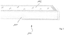
- Fig. 3 a lamp known from the prior art is shown, which is used as a wall lamp in the same way as the lamp according to the invention and is intended to emit light as deep as possible into a room.
- the luminaire 100 shown thus has an elongated, approximately cuboid shape and is fastened with its rear side to a wall (not shown) or a generally vertical mounting surface.
- the light is emitted via a light-emitting surface 115 formed on the top of the housing 110, so that the light in the sense indirect lighting is emitted onto a ceiling of the room in which the luminaire 100 is arranged.
- the most asymmetrical light emission possible must be inclined towards the front, i.e. into the room, which is achieved through the appropriate arrangement of the lighting means and the design of the associated optics.
- Fig. 1 shows a sketch of the lamp according to the invention in a cross-sectional view. The following description is based on the illustrated orientation of the luminaire relative to the vertical. However, the luminaire can in principle also be used in a different orientation for operation.
- the luminaire thus has an LED light source 1 with a plurality of LEDs 2 arranged in a plane E1 for emitting a first light. Furthermore, it has a frame element 6, which is preferably designed for fastening the lamp to a wall by means of a fastening plane 19 and which is preferably shaped like a truncated pyramid in a first approximation, the frame element 6 having a first edge region 61 that adjoins the base adjoins the corresponding truncated pyramid shape and is opposite the fastening plane 19, as well as a second edge region 62 opposite thereto, which is designed to hold the LED light source 1.
- a reflector element 5, which is arranged on the frame element 6, extends here between the second edge region 62 and the first edge region 61.
- the plane E1 in which the LEDs 2 are arranged is preferably oriented obliquely to the fastening plane 19, preferably in one Angle ⁇ of about 20 °.
- the LEDs 2, which can be arranged in the plane E1 either in a row or in a matrix-like manner, are thus oriented slightly inclined upwards.
- a light guide 4 is arranged above the reflector element and extends - viewed in a cross section perpendicular to the first plane E1 - starting from the first edge area 61 inwardly towards the LED light source 1, such that the first light emitted by the LEDs 2 through a first end face 41 of the light guide 4 facing the LED light source 1 shines into the light guide 4 and furthermore at least partially shines into the light guide 4 opposite direction to the reflector element 5 leaves and is thus emitted to the outside.
- the light guide 4 ends in the area of the first edge area 61 with the second end face 42.
- the light guide 4 is as shown in FIG Fig. 1 bulging or curved towards the LED light source 1 in such a way that the frontal first end surface 41 is aligned as parallel as possible to the plane E1 of the arrangement of the LEDs 2. This ensures that the light emitted by the LEDs 2 is coupled into the light guide 4 as efficiently as possible.
- the light guide 4 extends preferably flat in the area towards the second end face 42 or the first end area 61 of the frame element 6, so that a flat light-emitting surface 72 is formed in this area.
- the curvature of the light guide is designed in such a way that in the case of the in Fig. 1
- the light guide 4 here has light decoupling structures (not shown in more detail) which are designed in such a way that the first light at least partially leaves the light guide 4 via the planar light-emitting surface 72.
- these light decoupling structures can be implemented on the light emitting surface 72. Scattering particles provided within the material of the light guide 4 can also effect the coupling-out of light.
- the light guide 4 is shaped in such a way that - viewed in the cross section shown - it tapers in the direction of the second end face 42.
- the thickness of the light guide 4 in the area of the light entry surface 41 is approximately four times as great as in the area of the second end face 42.
- the light guide 4 is preferably made of a slightly scattering, but otherwise clear plastic, with PMMA, PC or silicone in particular being considered.
- the reflector 5 is located below the light guide 4, which is preferably made highly reflective and can either be arranged as a separate component on the underside of the light guide 4 or implemented by a corresponding reflective coating of the light guide 4. In both cases, the reflector 5 follows the curvature of the light guide 4.
- Fig. 2 shows the distribution of the emitted light in a lamp according to the present invention.
- the light output or the light emission by the luminaire has an asymmetrical light distribution, the light output taking place in the opposite direction to the fastening plane 19, preferably at a radiation angle of approximately 135 ° with respect to the fastening plane 19.
- a white reflector 5 also significantly increases the proportion of light in the rear half-space (C90-C270).
- LOR the so-called LOR.
- the light distribution shown corresponds to a diffused light guide with a size ratio of 4: 1 between the first and second end face 41 and 42 and a highly reflective reflector 5, whereby the light output can be influenced in the desired manner by the above-mentioned points.
- the lamp according to the invention can also be used in furniture, for example. This is made possible by the fact that the lamp according to the invention, due to its compact design, also allows integration in furniture.
- the lamp according to the invention as an orientation lamp or so-called bollard lamp. In this case a rotation of the optical system by 180 ° is necessary.
- the lamp according to the invention offers the advantage of optimal wall irradiation or so-called ceiling washing, the desired light distribution being achieved with a very compact design.
- light can be emitted in an asymmetrically distributed manner with the aid of the lamp according to the invention.
- the lamp can be designed with extremely small dimensions, the lamp can be designed in different lengths in the longitudinal direction.
Landscapes
- Physics & Mathematics (AREA)
- General Physics & Mathematics (AREA)
- Optics & Photonics (AREA)
- Non-Portable Lighting Devices Or Systems Thereof (AREA)
- Planar Illumination Modules (AREA)
Abstract
Description
- Die vorliegende Erfindung betrifft eine LED-Leuchte mit mehreren, in einer Ebene angeordneten LEDs und einem Lichtleiter. Insbesondere ist die erfindungsgemäße Leuchte dazu vorgesehen, Licht mit einer stark asymmetrischen Lichtverteilung abzugeben.
- Stark asymmetrische Lichtverteilungen werden oft in atypischen Beleuchtungssituationen verwendet, beispielsweise dann, wenn mit einer Wandleuchte ein Raum insgesamt möglichst blendfrei ausgeleuchtet werden soll. In derartigen Fällen ist es vorteilhaft, das Licht möglichst tief in den Raum zu bringen. Dabei sind Überhellungen an der Decke und an der Wand, die vor allem in der Nähe der Leuchte entstehen können, zu vermeiden. Für solche extremen Lichtumlenkungen werden optische Systeme benötigt, die entweder relativ viel Einbauraum benötigen und dementsprechend groß ausgeführt sind, oder - wenn der Raum nicht verfügbar bzw. nur begrenzt ist - eine komplizierte Geometrie aufweisen.
- Aus dem Stand der Technik sind LED-Leuchten bekannt, die Linsen aufweisen, mit deren Hilfe eine stark asymmetrische Lichtverteilung erzielt wird. Derartige Linsen weisen oft eine sehr komplizierte Geometrie auf, was zu Problemen hinsichtlich der akzeptablen Fertigungstoleranzen sowie der Positionierung in Bezug auf die zugehörige LED-Lichtquelle führt. Besonders im Fall von in der Beleuchtungstechnik gerne eingesetzten Extrusions-Linsen stellen allerdings Fertigungstoleranzen ein Problem dar. Sie führen zu Ungenauigkeiten und sogenannten Farbshifts in der Lichtverteilung. Generell stellt sich das Problem dar, dass je kleiner der für die Optik zur Verfügung stehende Raum ist, desto schwieriger die entsprechenden Fertigungstoleranzen eingehalten werden können.
- Der vorliegenden Erfindung liegt die Aufgabe zugrunde, eine im Hinblick auf die oben genannten Problemstellungen verbesserte Leuchte bereitzustellen. Insbesondere soll die Leuchte sich dazu eignen, Licht mit einer stark asymmetrischen Lichtverteilung abzugeben. Gleichzeitig soll die Leuchte derart gestaltet sein, dass sie eine möglichst kompakte Bauform aufweist.
- Die Aufgabe wird gemäß der vorliegenden Erfindung mit dem in dem unabhängigen Anspruch genannten Gegenstand gelöst. Vorteilhafte Weiterbildungen der Erfindung sind Gegenstand der abhängigen Ansprüche.
- Gemäß der vorliegenden Erfindung ist eine Leuchte vorgesehen, aufweisend
- eine LED-Lichtquelle mit mehreren, in einer Ebene angeordneten LEDs zur Abstrahlung eines ersten Lichts,
- ein Rahmenelement zur Halterung der LED-Lichtquelle, wobei das Rahmenelement einen ersten Randbereich sowie einen dem ersten Randbereich gegenüberliegenden zweiten Randbereich aufweist, der die LED-Lichtquelle haltend gestaltet ist,
- ein Reflektor-Element, welches sich zwischen dem ersten Randbereich und dem zweiten Randbereich des Rahmenelements erstreckt, sowie
- einen Lichtleiter, der über dem Reflektor-Element angeordnet ist und sich
- in einem Querschnitt senkrecht zu der Ebene der LEDs betrachtet - ausgehend von dem ersten Randbereich zu der LED-Lichtquelle hin erstreckt, derart, dass das erste Licht durch eine der LED-Lichtquelle zugewandte stirnseitige Endfläche des Lichtleiters in diesen einstrahlt und im Weiteren zumindest teilweise den Lichtleiter in entgegengesetzter Richtung zu dem Reflektor-Element verlässt und nach außen abgegeben wird.
- Die Ausgestaltung der erfindungsgemäßen Leuchte erlaubt es, die Optik zu Beeinflussung der Lichtabgabe möglichst kompakt zu gestalten, so dass eine kleinbauende Leuchte realisiert werden kann. Trotz allem wird in gewünschter Weise asymmetrisch Licht abgegeben, so dass sich die Leuchte für den eingangs geschilderten Anwendungszweck als Wandleuchte, mit deren Hilfe ein Raum möglichst vollständig ausgeleuchtet werden soll, gut eignet.
- Das Rahmenelement der erfindungsgemäßen Leuchte kann hierbei zur Befestigung der Leuchte an einer Wand mittels einer Befestigungsebene ausgelegt sein, wobei das
- Rahmenelement vorzugsweise in erster Näherung Pyramidenstumpf-artig geformt gestaltet ist. Insbesondere kann hierbei vorgesehen sein, dass die erste Ebene, welche durch die Anordnung der LEDs definiert ist, gegenüber der Befestigungsebene der Leuchte geneigt ist, vorzugsweise in einem Winkel von etwa 20°. Wird die Leuchte wie vorgesehen also an einer Wand bzw. einer vertikalen Montagefläche angeordnet, so sind die LEDs leicht nach oben geneigt ausgerichtet, wodurch die angestrebte asymmetrische Lichtabgabe weiter optimiert werden kann.
- Vorzugsweise weist hierbei der Lichtleiter in einem an den ersten Randbereich angrenzenden Bereich eine sich plan in einer zweiten Ebene erstreckende Lichtabstrahlfläche auf, wobei die erste und zweite Ebene einen Winkel kleiner als 90° einschließen. Vorzugsweise kann dieser Winkel im Bereich zwischen 60° und 80° liegen, besonders bevorzugt im Bereich von etwa 70°. Insbesondere kann hierbei vorgesehen sein, dass die zweite Ebene für den Fall, dass die Leuchte an einer vertikalen Wand angeordnet ist, sich im Wesentlichen horizontal erstreckt.
- Der Lichtleiter kann hierbei in einem der LED-Lichtquelle zugewandten Bereich gewölbt bzw. gekrümmt ausgeführt sein, so dass eine der LED-Lichtquelle zugewandte Lichteintrittsfläche des Lichtleiters parallel zur ersten Ebene verläuft. Hierdurch wird einerseits die Lichteinkopplung der LEDs in den Lichtleiter optimiert, andererseits trägt diese spezielle Ausgestaltung dazu bei, dass die Optik besonders kompakt gehalten werden kann.
- Der Lichtleiter kann dabei ausgehend von dem ersten Randbereich zu dem zweiten Randbereich hin eine zunehmende Dicke, vorzugsweise eine kontinuierlich zunehmende Dicke aufweisen. Insbesondere kann vorgesehen sein, dass die Dicke des Lichtleiters im Lichteintrittsbereich etwa viermal so groß ist wie am gegenüberliegenden Ende.
- Der Lichtleiter weist hierbei vorzugsweise an seiner dem Reflektor abgewandten Seite Lichtauskoppelstrukturen auf, die derart gestaltet sind, dass das erste Licht zumindest teilweise den Lichtleiter über die plane Lichtabstrahlfläche verlässt.
- Die erfindungsgemäße Ausgestaltung der Leuchte erlaubt es, wie bereits erwähnt, eine Lichtabgabe mit einer asymmetrischen Lichtverteilung zu erzielen, wobei vorzugsweise diese Lichtabgabe in der entgegengesetzten Richtung zu der Befestigungsebene der Leuchte vorliegt, und wobei insbesondere der Abstrahlwinkel, bezogen auf die Befestigungsebene, etwa 135° beträgt.
- Die erfindungsgemäße Lösung zeichnet sich insbesondere durch die einfache Geometrie des Lichtleiters aus und ermöglicht die Nutzung große Radien, durch die Verlustlicht vermieden wird. Die Fertigungstoleranzen sind bei der erfindungsgemäßen Ausgestaltung in einem Extrusionsprozess einfach zu bewältigen. Darüber hinaus ist der benötigte Bauraum sehr klein und die generierte Lichtverteilung erreicht die gewünschte Asymmetrie, um das abgestrahlte Licht der Leuchte in die Raumtiefe zu bringen.
- Die Erfindung wird im Folgenden anhand eines Ausführungsbeispiels und mit Bezug auf die Zeichnungen näher erläutert. Es zeigen:
- Fig. 1
- eine Querschnitt-Skizze einer erfindungsgemäßen Leuchte;
- Fig. 2
- die Verteilung des abgestrahlten Lichts der Leuchte gemäß
Fig. 1 und - Fig. 3
- eine Leuchte gemäß dem Stand der Technik.
- Bevor die erfindungsgemäße Ausgestaltung der Leuchte im Detail erläutert wird, soll zunächst die der Erfindung zugrundeliegende Aufgabenstellung näher erläutert werden. Hierzu ist in
Fig. 3 eine aus dem Stand der Technik bekannte Leuchte gezeigt, die in gleicher Weise wie auch die erfindungsgemäße Leuchte als Wandleuchte zum Einsatz kommt und dazu vorgesehen ist, möglichst tief in einen Raum hinein Licht abzustrahlen. - Die in
Fig. 3 gezeigte Leuchte 100 weist somit eine längliche, etwa quaderförmige Form auf und ist mit ihrer Rückseite an einer nicht dargestellten Wand oder generell vertikalen Montagefläche befestigt. Die Lichtabgabe erfolgt über eine an der Oberseite des Gehäuses 110 ausgebildete Lichtabstrahlfläche 115, so dass das Licht im Sinne einer Indirektbeleuchtung auf eine Decke des Raums, in dem die Leuchte 100 angeordnet ist, abgegeben wird. Um eine möglichst gleichmäßige Beleuchtung erhalten zu können, muss hierbei eine möglichst stark asymmetrische Lichtabgabe schräg nach vorne hin, also in den Raum hinein erfolgen, was durch die entsprechende Anordnung der Leuchtmittel sowie Ausgestaltung der zugehörigen Optik erreicht wird. - Mit Hilfe der vorliegenden Erfindung wird eine Lösung zur Verfügung gestellt, welche es erlaubt, trotz einer äußerst kompakten Ausgestaltung der Optik und ihrem einfachen Aufbau die gewünschte stark asymmetrische Lichtabgabe zu erzielen. Diese Lösung soll nunmehr mit Bezug auf die
Fig. 1 und 2 näher erläutert werden. -
Fig. 1 zeigt hierzu eine Skizze der erfindungsgemäßen Leuchte in einer Querschnittansicht. In der nachfolgenden Beschreibung wird von der dargestellten Orientierung der Leuchte gegenüber der Vertikalen ausgegangen. Allerdings kann die Leuchte grundsätzlich zum Betrieb auch in einer anderen Orientierung verwendet werden. - Die Leuchte weist also eine LED-Lichtquelle 1 mit mehreren, in einer Ebene E1 angeordneten LEDs 2 zur Abstrahlung eines ersten Lichts auf. Weiterhin weist sie ein Rahmenelement 6 auf, welches vorzugsweise zur Befestigung der Leuchte an einer Wand mittels einer Befestigungsebene 19 ausgelegt ist und das vorzugsweise in erster Näherung Pyramidenstumpf-artig geformt gestaltet ist, wobei das Rahmenelement 6 einen ersten Randbereich 61 aufweist, der an die Grundfläche der entsprechenden Pyramidenstumpfform angrenzt und der Befestigungsebene 19 gegenüberliegt, sowie einen hierzu gegenüberliegenden zweiten Randbereich 62, der die LED-Lichtquelle 1 haltend gestaltet ist. Ein Reflektor-Element 5, welches auf dem Rahmenelement 6 angeordnet ist, erstreckt sich hierbei zwischen dem zweiten Randbereich 62 und dem ersten Randbereich 61. Die Ebene E1 in der die LEDs 2 angeordnet sind, ist vorzugsweise schräg zur Befestigungsebene 19 ausgerichtet, bevorzugt in einem Winkel α von etwa 20°. Damit sind die LEDs 2, die in der Ebene E1 entweder in einer Reihe oder matrixartig angeordnet sein können, leicht nach oben geneigt ausgerichtet.
- Ein Lichtleiter 4 ist über dem Reflektor-Element angeordnet und erstreckt sich - in einem Querschnitt senkrecht zu der ersten Ebene E1 betrachtet - ausgehend von dem ersten Randbereich 61 einwärts zu der LED-Lichtquelle 1 hin, derart, dass das von den LEDs 2 abgegebene erste Licht durch eine der LED-Lichtquelle 1 zugewandte stirnseitige erste Endfläche 41 des Lichtleiters 4 in diesen einstrahlt und im Weiteren zumindest teilweise den Lichtleiter 4 in entgegengesetzter Richtung zu dem Reflektor-Element 5 verlässt und somit nach außen abgegeben wird. Der Lichtleiter 4 endet im Bereich des ersten Randbereichs 61 mit der zweiten Stirnfläche 42.
- Der Lichtleiter 4 ist entsprechend der Darstellung von
Fig. 1 sich zur LED-Lichtquelle 1 hin vorwölbend bzw. gekrümmt geformt, derart, dass die stirnseitige erste Endfläche 41 möglichst parallel zur Ebene E1 der Anordnung der LEDs 2 ausgerichtet ist. Hierdurch ist sichergestellt, dass das von den LEDs 2 abgegebene Licht möglichst effizient in den Lichtleiter 4 eingekoppelt wird. - Der Lichtleiter 4 erstreckt sich hierbei im Bereich zu der zweiten Stirnfläche 42 bzw. dem ersten Endbereich 61 des Rahmenelements 6 hin vorzugsweise plan, so dass in diesem Bereich eine plane Lichtabstrahlfläche 72 gebildet wird. Insbesondere ist hierbei die Krümmung des Lichtleiters derart ausgeführt, dass bei der in
Fig. 1 dargestellten Anordnung der Leuchte an einer Wand, also bei vertikal verlaufender Befestigungsebene 19, die Lichtabstrahlfläche 72 im Wesentlichen horizontal ausgerichtet ist. - Der Lichtleiter 4 weist hierbei - nicht näher dargestellte - Lichtauskoppelstrukturen auf, die derart gestaltet sind, dass das erste Licht zumindest teilweise den Lichtleiter 4 über die plane Lichtabstrahlfläche 72 verlässt. Insbesondere können diese Lichtauskoppelstrukturen an der Lichtabstrahlfläche 72 ausgeführt sein. Auch innerhalb des Materials des Lichtleiters 4 vorgesehene Streupartikel können die Lichtauskopplung bewirken.
- Wie ferner der Darstellung von
Fig. 1 entnommen werden kann, ist der Lichtleiter 4 derart geformt, dass er sich - in dem dargestellten Querschnitt betrachtet - in Richtung zu der zweiten Stirnfläche 42 hin verjüngt. Insbesondere kann vorgesehen sein, dass die Dicke des Lichtleiters 4 im Bereich der Lichteintrittsfläche 41 in etwa viermal so groß ist wie im Bereich der zweiten Stirnfläche 42. Insbesondere liegt vorzugsweise eine kontinuierliche, stetige Verjüngung des Lichtleiters 4 vor. - Der Lichtleiter 4 besteht vorzugsweise aus einem leicht streuendem, ansonsten allerdings klaren Kunststoff, wobei hierbei insbesondere an PMMA, PC oder Silikon zu denken ist. Unterhalb des Lichtleiters 4 befindet sich wie bereits erwähnt der Reflektor 5, der vorzugsweise hochverspiegelt ausgeführt ist und entweder als separates Bauelement an der Unterseite des Lichtleiters 4 angeordnet sein kann oder durch eine entsprechende reflektierende Beschichtung des Lichtleiters 4 realisiert wird. In beiden Fällen folgt hierbei der Reflektor 5 der Krümmung des Lichtleiters 4.
- Die angestrebte Licht-Auskopplung aus dem Lichtleiter 4 wird durch
- die Form des Lichtleiters (d. h. den Grad der Verjüngung und den Biegeradius des Lichtleiters)
- Streupartikel im Material des Lichtleiters
- den Reflektor unterhalb des Lichtleiters
-
Fig. 2 zeigt hierzu die Verteilung des abgestrahlten Lichts bei einer Leuchte entsprechend der vorliegenden Erfindung. Die Lichtabgabe bzw. die Lichtabstrahlung durch die Leuchte weist wie erwähnt eine asymmetrische Lichtverteilung auf, wobei die Lichtabgabe in der entgegengesetzten Richtung zu der Befestigungsebene 19 erfolgt, vorzugsweise in einem Abstrahlwinkel von etwa 135° bezogen auf die Befestigungsebene 19. - Je mehr Streupartikel in dem Lichtleitermaterial des Lichtleiters angeordnet sind, desto lambertischer wird die Lichtverteilung. Ein weißer Reflektor 5 erhöht ferner deutlich den Lichtanteil in dem hinteren Halbraum (C90 - C270). Je größer das Verhältnis zwischen der Lichteintrittsfläche 41 des Lichtleiters 4 und der Fläche des Lichtleiterendes 42 ist, desto höher der sogenannte LOR. Insbesondere hat sich herausgestellt, dass bei einem größeren entsprechenden Verhältnis eine vorteilhafte Ausleuchtung des Raumes erzielt werden kann. Beispielsweise wird bei einem Faktor 4 eine verhältnismäßig breite Lichtverteilung in der C90/C270-Ebene erzielt.
- Die in
Fig. 2 dargestellte Lichtverteilung entspricht einem eindiffusierten Lichtleiter mit einem Größenverhältnis 4:1 zwischen der ersten und zweiten stirnseitigen Endfläche 41 und 42 sowie einem hochspiegelnden Reflektor 5, wobei durch die oben genannten Punkte die Lichtabgabe in gewünschter Weise beeinflusst werden kann. - Die erfindungsgemäße Leuchte kann beispielsweise auch bei Möbeln Verwendung finden. Dies wird dadurch ermöglicht, dass die erfindungsgemäße Leuchte aufgrund ihrer kompakten Ausgestaltung eine Integration auch in Möbel erlaubt.
- Ferner wäre es denkbar, die erfindungsgemäße Leuchte als Orientierungsleuchte oder sogenannte Pollerleuchte zu nutzen. In diesem Fall ist eine Drehung des optischen Systems um 180° erforderlich.
- Die erfindungsgemäße Leuchte bietet aufgrund der Kombination von sich verjüngendem Lichtleiter, der erfindungsgemäßen Anordnung der LED-Leuchtmittel und dem Reflektor den Vorteil einer optimalen Wandbestrahlung bzw. eines sogenannten Ceiling Washing, wobei die gewünschte Lichtverteilung bei einem sehr kompakten Design erzielt wird. Insbesondere lässt sich also mit Hilfe der erfindungsgemäßen Leuchte besonders geeignet Licht asymmetrisch verteilt abgeben. Dabei kann die Leuchte mit äußerst kleinen Abmessungen gestaltet werden, wobei in Längsrichtung die Leuchte in verschiedenen Längen ausgeführt sein kann.
Claims (11)
- Leuchte, aufweisend- eine LED-Lichtquelle (1) mit mehreren, in einer Ebene (E1) angeordneten LEDs (2) zur Abstrahlung eines ersten Lichts,- ein Rahmenelement (6) zur Halterung der LED-Lichtquelle (1), wobei das Rahmenelement (6) einen ersten Randbereich (61) sowie einen dem ersten Randbereich (61) gegenüberliegenden zweiten Randbereich (62) aufweist, der die LED-Lichtquelle (1) haltend gestaltet ist,- ein Reflektor-Element (5), welches sich zwischen dem ersten Randbereich (61) und dem zweiten Randbereich (62) des Rahmenelements (6) erstreckt,- einen Lichtleiter (4), der über dem Reflektor-Element (5) angeordnet ist und sich - in einem Querschnitt senkrecht zu der Ebene (E1) der LEDs (2) betrachtet- ausgehend von dem ersten Randbereich (61) zu der LED-Lichtquelle (1) hin erstreckt, derart, dass das erste Licht durch eine, der LED-Lichtquelle (1) zugewandte stirnseitige Endfläche (41) des Lichtleiters (4) in diesen einstrahlt und im Weiteren zumindest teilweise den Lichtleiter (4) in entgegengesetzter Richtung zu dem Reflektor-Element (5) verlässt und nach außen abgegeben wird.
- Leuchte nach Anspruch 1,
dadurch gekennzeichnet,
dass das Rahmenelement (6) zur Befestigung der Leuchte an einer Wand mittels einer Befestigungsebene (19) ausgelegt ist, wobei das Rahmenelement (6) vorzugsweise in erster Näherung Pyramidenstumpf-artig geformt gestaltet ist, - Leuchte nach Anspruch 2,
dadurch gekennzeichnet,
dass die erste Ebene (E1) gegenüber der Befestigungsebene (19) geneigt ist, vorzugsweise in einem Winkel von etwa 20°. - Leuchte nach einem der vorherigen Ansprüche,
dadurch gekennzeichnet,
dass der Lichtleiter (4) in einem an den ersten Randbereich (62) angrenzenden Bereich eine sich plan in einer zweiten Ebene (E2) erstreckende Lichtabstrahlfläche aufweist. - Leuchte nach Anspruch 4,
dadurch gekennzeichnet,
dass die erste und zweite Ebene (E1, E2) einen Winkel kleiner als 90° einschließen, vorzugsweise einen Winkel zwischen 60" und 80°, besonders bevorzugt etwa 70°. - Leuchte nach Anspruch 5,
dadurch gekennzeichnet,
dass der Lichtleiter (4) in einem der LED-Lichtquelle (1) zugewandten Bereich gewölbt bzw. gekrümmt ausgeführt ist, so dass eine der LED-Lichtquelle (1) zugewandte Lichteintrittsfläche des Lichtleiters (4) parallel zur ersten Ebene (E1) verläuft. - Leuchte nach einem der Ansprüche 4 bis 6,
dadurch gekennzeichnet,
dass der Lichtleiter (4) Lichtauskoppelstrukturen aufweist, die derart gestaltet sind, dass das erste Licht zumindest teilweise den Lichtleiter (4) über die plane Abstrahlungsfläche verlässt. - Leuchte nach einem der vorherigen Ansprüche,
dadurch gekennzeichnet,
dass der Lichtleiter (4) ausgehend von dem ersten Randbereich (61) zu dem zweiten Randbereich (62) hin eine zunehmende Dicke, vorzugsweise eine kontinuierlich zunehmende Dicke aufweist. - Leuchte nach Anspruch 8,
dadurch gekennzeichnet,
dass die Dicke des Lichtleiters (4) im Bereich der Lichteintrittsfläche (41) etwa viermal so groß ist wie am gegenüberliegenden Endbereich (42). - Leuchte nach einem der vorhergehenden Ansprüche,
dadurch gekennzeichnet,
dass der Lichtleiter (4) aus einem Kunststoffmaterial, insbesondere aus PMMA oder PC, besteht,
wobei vorzugsweise in dem Lichtleiter (4) Streupartikel vorgesehen sind. - Leuchte nach einem der vorhergehenden Ansprüche,
dadurch gekennzeichnet,
dass die Lichtabgabe durch die Leuchte eine asymmetrische Lichtverteilung aufweist, wobei diese Lichtabgabe in der entgegengesetzten Richtung zu einer Befestigungsebene (19) der Leuchte abgestrahlt wird, vorzugsweise in einem Abstrahlwinkel von 135 Grad bezogen auf die Befestigungsebene (19).
Applications Claiming Priority (1)
| Application Number | Priority Date | Filing Date | Title |
|---|---|---|---|
| ATGM50065/2020U AT17178U1 (de) | 2020-03-20 | 2020-03-20 | LED-Leuchte |
Publications (2)
| Publication Number | Publication Date |
|---|---|
| EP3882517A1 true EP3882517A1 (de) | 2021-09-22 |
| EP3882517B1 EP3882517B1 (de) | 2022-08-03 |
Family
ID=75172997
Family Applications (1)
| Application Number | Title | Priority Date | Filing Date |
|---|---|---|---|
| EP21162492.9A Active EP3882517B1 (de) | 2020-03-20 | 2021-03-15 | Led-leuchte |
Country Status (2)
| Country | Link |
|---|---|
| EP (1) | EP3882517B1 (de) |
| AT (1) | AT17178U1 (de) |
Citations (5)
| Publication number | Priority date | Publication date | Assignee | Title |
|---|---|---|---|---|
| US4929866A (en) * | 1987-11-17 | 1990-05-29 | Mitsubishi Cable Industries, Ltd. | Light emitting diode lamp |
| JP2001229703A (ja) * | 1999-12-09 | 2001-08-24 | Matsushita Electric Works Ltd | 光照射装置 |
| US20120063164A1 (en) * | 2010-09-10 | 2012-03-15 | Young Lighting Technology Corporation | Light source apparatus and method of using light source apparatus |
| FR2993345A1 (fr) * | 2012-07-12 | 2014-01-17 | Ipselios | Dispositif d'eclairage type leche-mur a diodes electroluminescentes et guide de lumiere |
| DE102012019522A1 (de) * | 2012-10-05 | 2014-04-10 | LEDsSHINE GmbH | Flächenleuchte mit einer lichtleitenden Platte |
Family Cites Families (1)
| Publication number | Priority date | Publication date | Assignee | Title |
|---|---|---|---|---|
| DE202016002197U1 (de) * | 2016-04-01 | 2016-06-06 | Osram Gmbh | Direktstrahlende LED-Leuchte mit Entblendungsoptik |
-
2020
- 2020-03-20 AT ATGM50065/2020U patent/AT17178U1/de not_active IP Right Cessation
-
2021
- 2021-03-15 EP EP21162492.9A patent/EP3882517B1/de active Active
Patent Citations (5)
| Publication number | Priority date | Publication date | Assignee | Title |
|---|---|---|---|---|
| US4929866A (en) * | 1987-11-17 | 1990-05-29 | Mitsubishi Cable Industries, Ltd. | Light emitting diode lamp |
| JP2001229703A (ja) * | 1999-12-09 | 2001-08-24 | Matsushita Electric Works Ltd | 光照射装置 |
| US20120063164A1 (en) * | 2010-09-10 | 2012-03-15 | Young Lighting Technology Corporation | Light source apparatus and method of using light source apparatus |
| FR2993345A1 (fr) * | 2012-07-12 | 2014-01-17 | Ipselios | Dispositif d'eclairage type leche-mur a diodes electroluminescentes et guide de lumiere |
| DE102012019522A1 (de) * | 2012-10-05 | 2014-04-10 | LEDsSHINE GmbH | Flächenleuchte mit einer lichtleitenden Platte |
Also Published As
| Publication number | Publication date |
|---|---|
| AT17178U1 (de) | 2021-08-15 |
| EP3882517B1 (de) | 2022-08-03 |
Similar Documents
| Publication | Publication Date | Title |
|---|---|---|
| EP0846915B1 (de) | Innenraumleuchte | |
| EP2476949A2 (de) | Leuchte mit einem kastenförmigen Leuchtengehäuse und einem Lichtaustrittselement | |
| EP3207308B1 (de) | Wallwasher | |
| DE602004005872T2 (de) | Beleuchtung und methode zur beleuchtung | |
| DE10011378B4 (de) | Hohllichtleiterleuchte mit indirekter Lichtabstrahlung | |
| EP4034807B1 (de) | Leuchte mit bereich zur flächigen lichtabgabe | |
| EP3283820B1 (de) | Optisches system sowie anordnung zur lichtabgabe | |
| EP3882517B1 (de) | Led-leuchte | |
| EP1132679B1 (de) | Leuchtensystem | |
| EP3832194B1 (de) | Optisches system zum beeinflussen der lichtabgabe einer länglichen lichtquelle | |
| DE102023121516A1 (de) | Beleuchtungsvorrichtung | |
| EP3557124B1 (de) | Flache led-leuchte | |
| EP4168711B1 (de) | Anordnung zur lichtabgabe und leuchte | |
| DE10354462B4 (de) | Leuchte mit asymmetrischer Lichtabstrahlung | |
| EP4107426B1 (de) | Längliche leuchte | |
| DE202013101792U1 (de) | Leuchte mit optischem System zur Lichtabgabe über eine längliche Lichtaustrittsöffnung | |
| DE102018119606A1 (de) | Optisches Element für eine Leuchte, insbesondere Büroleuchte, sowie Leuchte | |
| EP3767159B1 (de) | Notlichtleuchte | |
| EP2107297B1 (de) | Leuchte, insbesondere Raumleuchte | |
| EP3112747A1 (de) | Optisches element zur beeinflussung der lichtabgabe einer länglichen lichtquelle | |
| EP3329178B1 (de) | Lichtleiterelement | |
| DE202014102021U1 (de) | Optisches Element für eine Lichtquelle einer Leuchte, sowie Leuchte | |
| DE202019104419U1 (de) | Optische Vorrichtung | |
| EP1843082A1 (de) | Deckenleuchte, insbesondere zur Verwendung in einem Flur | |
| AT16410U1 (de) | Anordnung zur flächigen Lichtabgabe |
Legal Events
| Date | Code | Title | Description |
|---|---|---|---|
| PUAI | Public reference made under article 153(3) epc to a published international application that has entered the european phase |
Free format text: ORIGINAL CODE: 0009012 |
|
| STAA | Information on the status of an ep patent application or granted ep patent |
Free format text: STATUS: THE APPLICATION HAS BEEN PUBLISHED |
|
| AK | Designated contracting states |
Kind code of ref document: A1 Designated state(s): AL AT BE BG CH CY CZ DE DK EE ES FI FR GB GR HR HU IE IS IT LI LT LU LV MC MK MT NL NO PL PT RO RS SE SI SK SM TR |
|
| STAA | Information on the status of an ep patent application or granted ep patent |
Free format text: STATUS: REQUEST FOR EXAMINATION WAS MADE |
|
| 17P | Request for examination filed |
Effective date: 20220321 |
|
| RBV | Designated contracting states (corrected) |
Designated state(s): AL AT BE BG CH CY CZ DE DK EE ES FI FR GB GR HR HU IE IS IT LI LT LU LV MC MK MT NL NO PL PT RO RS SE SI SK SM TR |
|
| RIC1 | Information provided on ipc code assigned before grant |
Ipc: F21V 8/00 20060101AFI20220323BHEP |
|
| GRAP | Despatch of communication of intention to grant a patent |
Free format text: ORIGINAL CODE: EPIDOSNIGR1 |
|
| STAA | Information on the status of an ep patent application or granted ep patent |
Free format text: STATUS: GRANT OF PATENT IS INTENDED |
|
| INTG | Intention to grant announced |
Effective date: 20220511 |
|
| GRAS | Grant fee paid |
Free format text: ORIGINAL CODE: EPIDOSNIGR3 |
|
| GRAA | (expected) grant |
Free format text: ORIGINAL CODE: 0009210 |
|
| STAA | Information on the status of an ep patent application or granted ep patent |
Free format text: STATUS: THE PATENT HAS BEEN GRANTED |
|
| AK | Designated contracting states |
Kind code of ref document: B1 Designated state(s): AL AT BE BG CH CY CZ DE DK EE ES FI FR GB GR HR HU IE IS IT LI LT LU LV MC MK MT NL NO PL PT RO RS SE SI SK SM TR |
|
| REG | Reference to a national code |
Ref country code: AT Ref legal event code: REF Ref document number: 1509020 Country of ref document: AT Kind code of ref document: T Effective date: 20220815 Ref country code: CH Ref legal event code: EP |
|
| REG | Reference to a national code |
Ref country code: DE Ref legal event code: R096 Ref document number: 502021000088 Country of ref document: DE |
|
| REG | Reference to a national code |
Ref country code: IE Ref legal event code: FG4D Free format text: LANGUAGE OF EP DOCUMENT: GERMAN |
|
| REG | Reference to a national code |
Ref country code: LT Ref legal event code: MG9D |
|
| REG | Reference to a national code |
Ref country code: NL Ref legal event code: MP Effective date: 20220803 |
|
| PG25 | Lapsed in a contracting state [announced via postgrant information from national office to epo] |
Ref country code: SE Free format text: LAPSE BECAUSE OF FAILURE TO SUBMIT A TRANSLATION OF THE DESCRIPTION OR TO PAY THE FEE WITHIN THE PRESCRIBED TIME-LIMIT Effective date: 20220803 Ref country code: RS Free format text: LAPSE BECAUSE OF FAILURE TO SUBMIT A TRANSLATION OF THE DESCRIPTION OR TO PAY THE FEE WITHIN THE PRESCRIBED TIME-LIMIT Effective date: 20220803 Ref country code: PT Free format text: LAPSE BECAUSE OF FAILURE TO SUBMIT A TRANSLATION OF THE DESCRIPTION OR TO PAY THE FEE WITHIN THE PRESCRIBED TIME-LIMIT Effective date: 20221205 Ref country code: NO Free format text: LAPSE BECAUSE OF FAILURE TO SUBMIT A TRANSLATION OF THE DESCRIPTION OR TO PAY THE FEE WITHIN THE PRESCRIBED TIME-LIMIT Effective date: 20221103 Ref country code: NL Free format text: LAPSE BECAUSE OF FAILURE TO SUBMIT A TRANSLATION OF THE DESCRIPTION OR TO PAY THE FEE WITHIN THE PRESCRIBED TIME-LIMIT Effective date: 20220803 Ref country code: LV Free format text: LAPSE BECAUSE OF FAILURE TO SUBMIT A TRANSLATION OF THE DESCRIPTION OR TO PAY THE FEE WITHIN THE PRESCRIBED TIME-LIMIT Effective date: 20220803 Ref country code: LT Free format text: LAPSE BECAUSE OF FAILURE TO SUBMIT A TRANSLATION OF THE DESCRIPTION OR TO PAY THE FEE WITHIN THE PRESCRIBED TIME-LIMIT Effective date: 20220803 Ref country code: FI Free format text: LAPSE BECAUSE OF FAILURE TO SUBMIT A TRANSLATION OF THE DESCRIPTION OR TO PAY THE FEE WITHIN THE PRESCRIBED TIME-LIMIT Effective date: 20220803 Ref country code: ES Free format text: LAPSE BECAUSE OF FAILURE TO SUBMIT A TRANSLATION OF THE DESCRIPTION OR TO PAY THE FEE WITHIN THE PRESCRIBED TIME-LIMIT Effective date: 20220803 |
|
| PG25 | Lapsed in a contracting state [announced via postgrant information from national office to epo] |
Ref country code: PL Free format text: LAPSE BECAUSE OF FAILURE TO SUBMIT A TRANSLATION OF THE DESCRIPTION OR TO PAY THE FEE WITHIN THE PRESCRIBED TIME-LIMIT Effective date: 20220803 Ref country code: IS Free format text: LAPSE BECAUSE OF FAILURE TO SUBMIT A TRANSLATION OF THE DESCRIPTION OR TO PAY THE FEE WITHIN THE PRESCRIBED TIME-LIMIT Effective date: 20221203 Ref country code: HR Free format text: LAPSE BECAUSE OF FAILURE TO SUBMIT A TRANSLATION OF THE DESCRIPTION OR TO PAY THE FEE WITHIN THE PRESCRIBED TIME-LIMIT Effective date: 20220803 Ref country code: GR Free format text: LAPSE BECAUSE OF FAILURE TO SUBMIT A TRANSLATION OF THE DESCRIPTION OR TO PAY THE FEE WITHIN THE PRESCRIBED TIME-LIMIT Effective date: 20221104 |
|
| PG25 | Lapsed in a contracting state [announced via postgrant information from national office to epo] |
Ref country code: SM Free format text: LAPSE BECAUSE OF FAILURE TO SUBMIT A TRANSLATION OF THE DESCRIPTION OR TO PAY THE FEE WITHIN THE PRESCRIBED TIME-LIMIT Effective date: 20220803 Ref country code: RO Free format text: LAPSE BECAUSE OF FAILURE TO SUBMIT A TRANSLATION OF THE DESCRIPTION OR TO PAY THE FEE WITHIN THE PRESCRIBED TIME-LIMIT Effective date: 20220803 Ref country code: DK Free format text: LAPSE BECAUSE OF FAILURE TO SUBMIT A TRANSLATION OF THE DESCRIPTION OR TO PAY THE FEE WITHIN THE PRESCRIBED TIME-LIMIT Effective date: 20220803 Ref country code: CZ Free format text: LAPSE BECAUSE OF FAILURE TO SUBMIT A TRANSLATION OF THE DESCRIPTION OR TO PAY THE FEE WITHIN THE PRESCRIBED TIME-LIMIT Effective date: 20220803 |
|
| REG | Reference to a national code |
Ref country code: DE Ref legal event code: R097 Ref document number: 502021000088 Country of ref document: DE |
|
| PG25 | Lapsed in a contracting state [announced via postgrant information from national office to epo] |
Ref country code: SK Free format text: LAPSE BECAUSE OF FAILURE TO SUBMIT A TRANSLATION OF THE DESCRIPTION OR TO PAY THE FEE WITHIN THE PRESCRIBED TIME-LIMIT Effective date: 20220803 Ref country code: EE Free format text: LAPSE BECAUSE OF FAILURE TO SUBMIT A TRANSLATION OF THE DESCRIPTION OR TO PAY THE FEE WITHIN THE PRESCRIBED TIME-LIMIT Effective date: 20220803 |
|
| PLBE | No opposition filed within time limit |
Free format text: ORIGINAL CODE: 0009261 |
|
| STAA | Information on the status of an ep patent application or granted ep patent |
Free format text: STATUS: NO OPPOSITION FILED WITHIN TIME LIMIT |
|
| PG25 | Lapsed in a contracting state [announced via postgrant information from national office to epo] |
Ref country code: AL Free format text: LAPSE BECAUSE OF FAILURE TO SUBMIT A TRANSLATION OF THE DESCRIPTION OR TO PAY THE FEE WITHIN THE PRESCRIBED TIME-LIMIT Effective date: 20220803 |
|
| 26N | No opposition filed |
Effective date: 20230504 |
|
| P01 | Opt-out of the competence of the unified patent court (upc) registered |
Effective date: 20230530 |
|
| REG | Reference to a national code |
Ref country code: DE Ref legal event code: R084 Ref document number: 502021000088 Country of ref document: DE |
|
| PG25 | Lapsed in a contracting state [announced via postgrant information from national office to epo] |
Ref country code: SI Free format text: LAPSE BECAUSE OF FAILURE TO SUBMIT A TRANSLATION OF THE DESCRIPTION OR TO PAY THE FEE WITHIN THE PRESCRIBED TIME-LIMIT Effective date: 20220803 |
|
| PG25 | Lapsed in a contracting state [announced via postgrant information from national office to epo] |
Ref country code: MC Free format text: LAPSE BECAUSE OF FAILURE TO SUBMIT A TRANSLATION OF THE DESCRIPTION OR TO PAY THE FEE WITHIN THE PRESCRIBED TIME-LIMIT Effective date: 20220803 |
|
| REG | Reference to a national code |
Ref country code: BE Ref legal event code: MM Effective date: 20230331 |
|
| PG25 | Lapsed in a contracting state [announced via postgrant information from national office to epo] |
Ref country code: LU Free format text: LAPSE BECAUSE OF NON-PAYMENT OF DUE FEES Effective date: 20230315 |
|
| REG | Reference to a national code |
Ref country code: IE Ref legal event code: MM4A |
|
| PG25 | Lapsed in a contracting state [announced via postgrant information from national office to epo] |
Ref country code: IE Free format text: LAPSE BECAUSE OF NON-PAYMENT OF DUE FEES Effective date: 20230315 |
|
| PG25 | Lapsed in a contracting state [announced via postgrant information from national office to epo] |
Ref country code: BE Free format text: LAPSE BECAUSE OF NON-PAYMENT OF DUE FEES Effective date: 20230331 |
|
| PG25 | Lapsed in a contracting state [announced via postgrant information from national office to epo] |
Ref country code: IT Free format text: LAPSE BECAUSE OF FAILURE TO SUBMIT A TRANSLATION OF THE DESCRIPTION OR TO PAY THE FEE WITHIN THE PRESCRIBED TIME-LIMIT Effective date: 20220803 |
|
| REG | Reference to a national code |
Ref country code: CH Ref legal event code: PL |
|
| PG25 | Lapsed in a contracting state [announced via postgrant information from national office to epo] |
Ref country code: BG Free format text: LAPSE BECAUSE OF FAILURE TO SUBMIT A TRANSLATION OF THE DESCRIPTION OR TO PAY THE FEE WITHIN THE PRESCRIBED TIME-LIMIT Effective date: 20220803 |
|
| PG25 | Lapsed in a contracting state [announced via postgrant information from national office to epo] |
Ref country code: BG Free format text: LAPSE BECAUSE OF FAILURE TO SUBMIT A TRANSLATION OF THE DESCRIPTION OR TO PAY THE FEE WITHIN THE PRESCRIBED TIME-LIMIT Effective date: 20220803 |
|
| PG25 | Lapsed in a contracting state [announced via postgrant information from national office to epo] |
Ref country code: CH Free format text: LAPSE BECAUSE OF NON-PAYMENT OF DUE FEES Effective date: 20240331 |
|
| PGFP | Annual fee paid to national office [announced via postgrant information from national office to epo] |
Ref country code: AT Payment date: 20250417 Year of fee payment: 5 |
|
| PGFP | Annual fee paid to national office [announced via postgrant information from national office to epo] |
Ref country code: FR Payment date: 20250324 Year of fee payment: 5 |
|
| PGFP | Annual fee paid to national office [announced via postgrant information from national office to epo] |
Ref country code: GB Payment date: 20250326 Year of fee payment: 5 |
|
| PG25 | Lapsed in a contracting state [announced via postgrant information from national office to epo] |
Ref country code: CY Free format text: LAPSE BECAUSE OF FAILURE TO SUBMIT A TRANSLATION OF THE DESCRIPTION OR TO PAY THE FEE WITHIN THE PRESCRIBED TIME-LIMIT; INVALID AB INITIO Effective date: 20210315 |
|
| PG25 | Lapsed in a contracting state [announced via postgrant information from national office to epo] |
Ref country code: HU Free format text: LAPSE BECAUSE OF FAILURE TO SUBMIT A TRANSLATION OF THE DESCRIPTION OR TO PAY THE FEE WITHIN THE PRESCRIBED TIME-LIMIT; INVALID AB INITIO Effective date: 20210315 |
|
| PG25 | Lapsed in a contracting state [announced via postgrant information from national office to epo] |
Ref country code: TR Free format text: LAPSE BECAUSE OF FAILURE TO SUBMIT A TRANSLATION OF THE DESCRIPTION OR TO PAY THE FEE WITHIN THE PRESCRIBED TIME-LIMIT Effective date: 20220803 |
|
| PGFP | Annual fee paid to national office [announced via postgrant information from national office to epo] |
Ref country code: DE Payment date: 20260320 Year of fee payment: 6 |