EP3882515A1 - Vehicle lamp - Google Patents
Vehicle lamp Download PDFInfo
- Publication number
- EP3882515A1 EP3882515A1 EP18939925.6A EP18939925A EP3882515A1 EP 3882515 A1 EP3882515 A1 EP 3882515A1 EP 18939925 A EP18939925 A EP 18939925A EP 3882515 A1 EP3882515 A1 EP 3882515A1
- Authority
- EP
- European Patent Office
- Prior art keywords
- light
- hologram film
- lamp
- reflection plate
- disposed
- Prior art date
- Legal status (The legal status is an assumption and is not a legal conclusion. Google has not performed a legal analysis and makes no representation as to the accuracy of the status listed.)
- Granted
Links
Images





Classifications
-
- F—MECHANICAL ENGINEERING; LIGHTING; HEATING; WEAPONS; BLASTING
- F21—LIGHTING
- F21S—NON-PORTABLE LIGHTING DEVICES; SYSTEMS THEREOF; VEHICLE LIGHTING DEVICES SPECIALLY ADAPTED FOR VEHICLE EXTERIORS
- F21S41/00—Illuminating devices specially adapted for vehicle exteriors, e.g. headlamps
- F21S41/20—Illuminating devices specially adapted for vehicle exteriors, e.g. headlamps characterised by refractors, transparent cover plates, light guides or filters
-
- F—MECHANICAL ENGINEERING; LIGHTING; HEATING; WEAPONS; BLASTING
- F21—LIGHTING
- F21S—NON-PORTABLE LIGHTING DEVICES; SYSTEMS THEREOF; VEHICLE LIGHTING DEVICES SPECIALLY ADAPTED FOR VEHICLE EXTERIORS
- F21S43/00—Signalling devices specially adapted for vehicle exteriors, e.g. brake lamps, direction indicator lights or reversing lights
- F21S43/20—Signalling devices specially adapted for vehicle exteriors, e.g. brake lamps, direction indicator lights or reversing lights characterised by refractors, transparent cover plates, light guides or filters
- F21S43/26—Refractors, transparent cover plates, light guides or filters not provided in groups F21S43/235 - F21S43/255
-
- F—MECHANICAL ENGINEERING; LIGHTING; HEATING; WEAPONS; BLASTING
- F21—LIGHTING
- F21S—NON-PORTABLE LIGHTING DEVICES; SYSTEMS THEREOF; VEHICLE LIGHTING DEVICES SPECIALLY ADAPTED FOR VEHICLE EXTERIORS
- F21S41/00—Illuminating devices specially adapted for vehicle exteriors, e.g. headlamps
- F21S41/30—Illuminating devices specially adapted for vehicle exteriors, e.g. headlamps characterised by reflectors
-
- F—MECHANICAL ENGINEERING; LIGHTING; HEATING; WEAPONS; BLASTING
- F21—LIGHTING
- F21S—NON-PORTABLE LIGHTING DEVICES; SYSTEMS THEREOF; VEHICLE LIGHTING DEVICES SPECIALLY ADAPTED FOR VEHICLE EXTERIORS
- F21S43/00—Signalling devices specially adapted for vehicle exteriors, e.g. brake lamps, direction indicator lights or reversing lights
- F21S43/30—Signalling devices specially adapted for vehicle exteriors, e.g. brake lamps, direction indicator lights or reversing lights characterised by reflectors
- F21S43/31—Optical layout thereof
-
- F—MECHANICAL ENGINEERING; LIGHTING; HEATING; WEAPONS; BLASTING
- F21—LIGHTING
- F21S—NON-PORTABLE LIGHTING DEVICES; SYSTEMS THEREOF; VEHICLE LIGHTING DEVICES SPECIALLY ADAPTED FOR VEHICLE EXTERIORS
- F21S43/00—Signalling devices specially adapted for vehicle exteriors, e.g. brake lamps, direction indicator lights or reversing lights
- F21S43/40—Signalling devices specially adapted for vehicle exteriors, e.g. brake lamps, direction indicator lights or reversing lights characterised by the combination of reflectors and refractors
-
- F—MECHANICAL ENGINEERING; LIGHTING; HEATING; WEAPONS; BLASTING
- F21—LIGHTING
- F21V—FUNCTIONAL FEATURES OR DETAILS OF LIGHTING DEVICES OR SYSTEMS THEREOF; STRUCTURAL COMBINATIONS OF LIGHTING DEVICES WITH OTHER ARTICLES, NOT OTHERWISE PROVIDED FOR
- F21V9/00—Elements for modifying spectral properties, polarisation or intensity of the light emitted, e.g. filters
- F21V9/40—Elements for modifying spectral properties, polarisation or intensity of the light emitted, e.g. filters with provision for controlling spectral properties, e.g. colour, or intensity
-
- G—PHYSICS
- G02—OPTICS
- G02B—OPTICAL ELEMENTS, SYSTEMS OR APPARATUS
- G02B5/00—Optical elements other than lenses
- G02B5/04—Prisms
- G02B5/045—Prism arrays
-
- G—PHYSICS
- G02—OPTICS
- G02B—OPTICAL ELEMENTS, SYSTEMS OR APPARATUS
- G02B5/00—Optical elements other than lenses
- G02B5/08—Mirrors
- G02B5/0808—Mirrors having a single reflecting layer
-
- G—PHYSICS
- G02—OPTICS
- G02B—OPTICAL ELEMENTS, SYSTEMS OR APPARATUS
- G02B5/00—Optical elements other than lenses
- G02B5/32—Holograms used as optical elements
-
- G—PHYSICS
- G03—PHOTOGRAPHY; CINEMATOGRAPHY; ANALOGOUS TECHNIQUES USING WAVES OTHER THAN OPTICAL WAVES; ELECTROGRAPHY; HOLOGRAPHY
- G03H—HOLOGRAPHIC PROCESSES OR APPARATUS
- G03H1/00—Holographic processes or apparatus using light, infrared or ultraviolet waves for obtaining holograms or for obtaining an image from them; Details peculiar thereto
- G03H1/02—Details of features involved during the holographic process; Replication of holograms without interference recording
- G03H1/0252—Laminate comprising a hologram layer
- G03H1/0256—Laminate comprising a hologram layer having specific functional layer
-
- G—PHYSICS
- G03—PHOTOGRAPHY; CINEMATOGRAPHY; ANALOGOUS TECHNIQUES USING WAVES OTHER THAN OPTICAL WAVES; ELECTROGRAPHY; HOLOGRAPHY
- G03H—HOLOGRAPHIC PROCESSES OR APPARATUS
- G03H2222/00—Light sources or light beam properties
- G03H2222/40—Particular irradiation beam not otherwise provided for
- G03H2222/46—Reconstruction beam at reconstruction stage
-
- G—PHYSICS
- G03—PHOTOGRAPHY; CINEMATOGRAPHY; ANALOGOUS TECHNIQUES USING WAVES OTHER THAN OPTICAL WAVES; ELECTROGRAPHY; HOLOGRAPHY
- G03H—HOLOGRAPHIC PROCESSES OR APPARATUS
- G03H2223/00—Optical components
- G03H2223/18—Prism
-
- G—PHYSICS
- G03—PHOTOGRAPHY; CINEMATOGRAPHY; ANALOGOUS TECHNIQUES USING WAVES OTHER THAN OPTICAL WAVES; ELECTROGRAPHY; HOLOGRAPHY
- G03H—HOLOGRAPHIC PROCESSES OR APPARATUS
- G03H2223/00—Optical components
- G03H2223/19—Microoptic array, e.g. lens array
-
- G—PHYSICS
- G03—PHOTOGRAPHY; CINEMATOGRAPHY; ANALOGOUS TECHNIQUES USING WAVES OTHER THAN OPTICAL WAVES; ELECTROGRAPHY; HOLOGRAPHY
- G03H—HOLOGRAPHIC PROCESSES OR APPARATUS
- G03H2223/00—Optical components
- G03H2223/24—Reflector; Mirror
-
- G—PHYSICS
- G03—PHOTOGRAPHY; CINEMATOGRAPHY; ANALOGOUS TECHNIQUES USING WAVES OTHER THAN OPTICAL WAVES; ELECTROGRAPHY; HOLOGRAPHY
- G03H—HOLOGRAPHIC PROCESSES OR APPARATUS
- G03H2250/00—Laminate comprising a hologram layer
- G03H2250/37—Enclosing the photosensitive material
-
- G—PHYSICS
- G03—PHOTOGRAPHY; CINEMATOGRAPHY; ANALOGOUS TECHNIQUES USING WAVES OTHER THAN OPTICAL WAVES; ELECTROGRAPHY; HOLOGRAPHY
- G03H—HOLOGRAPHIC PROCESSES OR APPARATUS
- G03H2250/00—Laminate comprising a hologram layer
- G03H2250/39—Protective layer
Definitions
- the present disclosure relates to a vehicle lamp for forming a three-dimensional lighting pattern.
- a vehicle 1 is provided with a lamp device 100 for stably securing a driver's view or informing other vehicles of a driving state of the vehicle 1 when an ambient light is low while driving.
- a vehicle lamp device includes a headlamp 10 installed at the front of a vehicle and a rear lamp installed at the rear of the vehicle.
- the headlamp is a lamp that lights the front and illuminates the front during driving at night.
- the rear lamp includes a stop lamp that lights up when a driver operates a brake and a turn signal lamp that indicates a driving direction of the vehicle.
- halogen lamps or gas discharge lamps are usually used, but in recent years, light-emitting diodes (LEDs) are in the spotlight as light sources for vehicle lamps.
- the LED can enhance a degree of freedom for design of a lamp by minimizing a size thereof and exhibit economical efficiency by virtue of a semi-permanent lifespan, but most of the LEDs are currently produced in a form of a package.
- the LED itself other than the package is under development as a semiconductor light-emitting device of converting a current into light, namely, an image displaying light source equipped in an electronic device such as an information communication device.
- the present disclosure is directed to providing a lamp capable of implementing a three-dimensional lighting pattern.
- the present disclosure is directed to providing a vehicle lamp having a three-dimensional lighting pattern and luminance of a predetermined level or more.
- the present disclosure is directed to providing a structure such that the three-dimensional lighting pattern implemented in a vehicle lamp capable of being seen constantly regardless of a direction of looking toward the lamp.
- the present disclosure provides a lamp including a light source emitting light, a hologram film in which an interference fringe of light is formed, a reflection plate disposed in a tilted state at a predetermined angle with the hologram film such that light emitted from the light source is reflected and the reflected light is incident on the hologram film obliquely, and a prism sheet disposed on one surface of the hologram film and including a plurality of concave-convex structures such that light passing through the hologram film is refracted in one direction, wherein the reflection plate is composed of a plurality of regions and at least one of the plurality of regions has a different reflectance from the remaining region.
- the prism sheet may be disposed on a surface facing one surface at which light reflected from the reflection plate is incident on both surfaces of the hologram film.
- each of the plurality of concave-convex structures may have an inclined surface that forms a predetermined angle with the hologram film.
- the angle between the inclined surface and the hologram film may be different depending on a position of each of the plurality of concave-convex structures.
- the hologram film may include a substrate made of an optically clear material, an optically clear adhesive (OCA) layer laminated on the substrate, a photopolymer layer laminated on the OCA layer, and a protective layer laminated on the photopolymer layer.
- OCA optically clear adhesive
- an interference fringe may be formed on the photopolymer layer such that the hologram pattern is formed by the light transmitting through the hologram film.
- a reflectance of the reflection plate may decrease as toward a lower side of the reflection plate.
- a light-shielding plate disposed in a direction opposite to a reflection surface of the reflection plate and disposed to be overlapped with the hologram film may be further included.
- an auxiliary light source for emitting light may be disposed at least a part of the light-shielding plate.
- a housing overlapped with at least one of the light source and the reflection plate and disposed to surround the lamp may be further included.
- an amount of light reaching eyes of an observer becomes constant regardless of a direction to look toward a lamp. Accordingly, the present disclosure allows the three-dimensional lighting pattern implemented in the lamp to look constant regardless of a direction of looking toward the lamp.
- a singular representation may include a plural representation unless it represents a definitely different meaning from the context.
- a lamp according to the present disclosure has a structure for providing a three-dimensional lighting pattern.
- a light ray should be irradiated onto a film in which an interference fringe is stored.
- the film at which the interference fringe is stored only waves having the same frequency as when the interference fringe is recorded are reproduced as a stereoscopic image, and other waves pass through the film at which the interference fringe is stored.
- the hologram image When the hologram image is implemented as a vehicle lamp, light passing through the film at which the interference fringe is stored is light that is substantially lost.
- a vehicle lamp should have brightness of a predetermined level or more, and since an amount of light lost is a lot when the hologram image is implemented, the hologram image is difficult to have brightness of a predetermined level or more.
- distortion of the image may occur depending on a direction viewed by an observer.
- the vehicle lamp is viewed by an observer from various angles, which causes many limitations in implementing the hologram image in the vehicle lamp.
- a lamp according to an embodiment of the present disclosure includes a light source, a hologram film, a reflection plate and a prism sheet.
- the present disclosure is not limited thereto, and the lamp according to the present disclosure may include more components than those described above.
- FIGS. 3 and 4 are conceptual diagrams illustrating a vehicle lamp according to the present disclosure.
- a light source 210 emits light.
- the light source 210 may be formed in various types such as a laser diode, a semiconductor light-emitting device, and an organic light-emitting diode. However, the type of light source is not limited thereto separately.
- the light source 210 is not disposed to face the hologram film 230 but is disposed to face the reflection plate 220.
- the light emitted from the light source 210 is not directly toward the hologram film 230, but toward the reflection plate 220.
- the reflection plate 220 is disposed in a tilted state at a predetermined angle with the hologram film 230 such that light emitted from the light source 210 is reflected and the reflected light is incident on the hologram film 230 obliquely.
- the reflection plate 220 may be composed of a plurality of regions, and at least one of the plurality of regions may have a different reflectance from the remaining region. This is for making an amount of light incident on the hologram film 230 for each region of the hologram film 230 different.
- a distance between each of the plurality of regions included in the hologram film 230 and the light source 210 may be different from each other.
- an amount of light incident to the region close to the light source 210 is greater than that to the region far from the light source 210. Therefore, a phenomenon in which brightness of the image is changed depending on a direction in which the holographic image is viewed.
- the present disclosure implements reflectance of the reflection plate 220 differently for each region such that an amount of light incident on each of the plurality of regions included in the hologram film 230 is uniform.
- reflectance of a lower region of the reflection plate 220 that is close to the light source 210 may be smaller than that of an upper region of the reflection plate 220 that is far from the light source 210.
- reflectance of the reflection plate 220 may increase in an upward direction of the reflection plate 220.
- the present disclosure concentrates light in a region far from the light source 210 among a plurality of regions included in the hologram film, thereby making an amount of light incident on the hologram film uniform.
- the hologram film 230 may have various structures.
- the hologram film 230 may include a substrate, an optically clear adhesive (OCA) layer, a photopolymer layer, and a base film.
- OCA optically clear adhesive
- the substrate should be made of an optically clear material.
- the substrate serves to support components constituting the hologram film 230.
- the substrate is disposed at one surface facing the reflection plate 220 of the both surfaces of the hologram film 230. Accordingly, the light reflected by the reflection plate 220 is first incident on the substrate.
- the OCA layer may be formed on the substrate.
- the OCA layer is used to bond the substrate and the photopolymer layer. When there are other means for bonding the photopolymer layer and the substrate, the OCA layer is not essential.
- a photopolymer layer is laminated on the OCA layer.
- An interference fringe is formed at the photopolymer layer, and a hologram image is formed due to the interference fringe.
- the hologram image is implemented by using only light having a frequency coinciding with the light irradiated when the interference fringe is formed among the light incident on the hologram film 230.
- the light having a frequency not coinciding with the light irradiated when the interference fringe is formed passes through the hologram film 230 as it is.
- a traveling path of the light having a frequency coinciding with the light irradiated when the interference fringe is formed is changed while passing passes through the photopolymer layer, however the traveling path of the light having a frequency not coinciding with the light irradiated when the interference fringe is formed is not changed and passes through the hologram film 230 as it is. Accordingly, light emitted from the same light source is dispersed in two different directions.
- the light reaching an observer is a light whose traveling path is changed while passing through the hologram film 230, and the light that does not change the traveling path while passing through the hologram film 230 does not reach the observer.
- the present disclosure provides a structure that allows the light whose traveling path is not changed reaches the observer while the light passes through the hologram film 230. This will be described later and the remaining structure of FIG. 5 will be described.
- a protective layer may be formed on the photopolymer layer.
- the protective layer serves to protect the photopolymer layer from physical impact.
- the protective layer may be implemented as various forms.
- the protective layer may include a first protective layer (Base film) for protecting a physical impact, and a second protective layer (Protection Film or Glass) for protecting the photopolymer layer from moisture, etc. introduced from the outside.
- the OCA layer may be formed between the first and second protective layers.
- the hologram film may include an encapsulation layer.
- the encapsulation layer is sealed by covering both an upper side and side surfaces of the photopolymer layer.
- the separate OCA layer may not be disposed between the photopolymer layer and the substrate.
- the OCA layer may be disposed between the substrate and the photopolymer layer even when the encapsulation layer is used.
- a prism sheet is laminated on the protective layer.
- the prism sheet allows the light whose traveling path is not changed to reach the observer while passes through the hologram film 230.
- the prism sheet 231 includes a plurality of concave-convex structures such that the light passing through the hologram film 230 is refracted in one direction.
- FIG. 6 is a conceptual diagram illustrating a cross-section of a prism sheet.
- a plurality of concave-convex structures 231' are formed at the prism sheet 231.
- Each of the concave-convex structures 231' has an inclined surface that forms a predetermined angle with the hologram film 230. As the light passing through the hologram film 230 is refracted by the inclined surface, the traveling path of the light is changed.
- the light whose traveling path is not changed while passing through the hologram film 230 is refracted by the inclined surface, and proceeds in the same direction as the direction in which the hologram image is formed. Accordingly, brightness of the hologram image may increase.
- an angle between the inclined surface and the hologram film 230 may be different depending on a position of each of the plurality of concave-convex structures.
- the traveling path of the light that does not change the traveling path while passing through the hologram film 230 may be different depending on a position at which the light passes.
- the present disclosure allows the angle formed by the inclined surface and the hologram film 230 to be different depending on a position of the concave-convex structures in order to concentrate the light traveling in various directions to a designated position.
- the angle between the inclined surface and the hologram film 230 may decrease as toward a lower side of the hologram film 230.
- the present disclosure increases brightness of the hologram image by concentrating the light lost in the direction in which the hologram image is formed while passing through the hologram film 230. Accordingly, the present disclosure allows the hologram image to have sufficient brightness to be used in a vehicle lamp.
- the above-described vehicle lamp may have a shape in which a plurality of modules 200a to 200c are disposed at a predetermined interval.
- the modules may be disposed in various forms, and thus various types of lighting patterns can be implemented.
- the vehicle lamp according to the present disclosure may further include a light-shielding plate 240 disposed in a direction opposite to the reflection surface of the reflection plate 220 to be overlapped with the hologram film 230.
- FIG. 8 is a conceptual diagram illustrating a vehicle lamp including a light-shielding plate
- FIG. 9 is a conceptual diagram illustrating a shape of a lighting pattern according to a presence of a light-shielding plate.
- a light-shielding plate 240 overlapped with the hologram film 230 may be disposed in a rear direction of the reflection plate 220.
- the presence of the light-shielding plate 240 may not significantly affect the holographic image, but when the hologram image is not implemented, that is, when no light is emitted from the light source 210, the light-shielding plate 240 determines a shape of the lamp.
- the structure disposed inside the lamp is exposed to an outside when the light is not emitted from the light source 210. This may adversely affect aesthetics of the lamp.
- the light-shielding plate 240 is installed at the rear side of the reflection plate 220 as shown in (b) of FIG. 9 , even when light is not emitted from the light source 210, the structure inside the lamp is not exposed to the outside.
- an auxiliary light source for emitting light may be disposed at the light-shielding plate 240.
- the auxiliary light source may be used to increase an amount of light in the hologram image when the hologram image is implemented.
- the auxiliary light source may be turned on only when the light source is turned on.
- the present disclosure improves the aesthetics of the lamp and improves the brightness of the hologram image via the above-described light-shielding plate 240.
- the present disclosure may further include a housing such that a part of the vehicle lamp is not exposed to the outside.
- FIGS. 10 and 11 are conceptual diagrams illustrating a vehicle lamp not including a housing
- FIGS. 12 and 13 are conceptual diagrams illustrating a vehicle lamp including a housing.
- the light source 210 irradiating light to the hologram film 230 and the reflection plate 220 should not be overlapped with the hologram film 230.
- the hologram film 230 is overlapped with the light source 210 or the reflection plate 220, since the shape of the light source 210 or the reflection plate 220 is exposed to the outside of the hologram image, it is difficult to form a complete hologram image.
- the light source 210 should be disposed at a position that does not be overlapped with the hologram film 230, which increases a size of the lamp and hinders aesthetics.
- a light source, a reflection plate and a support means for supporting the hologram film are exposed to the outside to hinder aesthetics of the lamp.
- the present disclosure may further include a housing 300 overlapped with at least one of the light source 210 and the reflection plate 220 and disposed to surround the lamp.
- the housing 300 prevents the light source 210, the reflection plate 220, and the support means for supporting the hologram film 230 from being exposed to the outside. Accordingly, the present disclosure improves aesthetics of the vehicle lamp.
- an amount of light reaching eyes of an observer becomes constant regardless of a direction to look toward a lamp. Accordingly, the present disclosure allows the three-dimensional lighting pattern implemented in the lamp to look constant regardless of a direction of looking toward the lamp.
Landscapes
- Physics & Mathematics (AREA)
- Engineering & Computer Science (AREA)
- General Engineering & Computer Science (AREA)
- General Physics & Mathematics (AREA)
- Optics & Photonics (AREA)
- Spectroscopy & Molecular Physics (AREA)
- Non-Portable Lighting Devices Or Systems Thereof (AREA)
- Diffracting Gratings Or Hologram Optical Elements (AREA)
- Lighting Device Outwards From Vehicle And Optical Signal (AREA)
Abstract
Description
- The present disclosure relates to a vehicle lamp for forming a three-dimensional lighting pattern.
- Referring to
FIGS. 1 and 2 , in general, avehicle 1 is provided with alamp device 100 for stably securing a driver's view or informing other vehicles of a driving state of thevehicle 1 when an ambient light is low while driving. - A vehicle lamp device includes a
headlamp 10 installed at the front of a vehicle and a rear lamp installed at the rear of the vehicle. The headlamp is a lamp that lights the front and illuminates the front during driving at night. The rear lamp includes a stop lamp that lights up when a driver operates a brake and a turn signal lamp that indicates a driving direction of the vehicle. In general, halogen lamps or gas discharge lamps are usually used, but in recent years, light-emitting diodes (LEDs) are in the spotlight as light sources for vehicle lamps. - The LED can enhance a degree of freedom for design of a lamp by minimizing a size thereof and exhibit economical efficiency by virtue of a semi-permanent lifespan, but most of the LEDs are currently produced in a form of a package. The LED itself other than the package is under development as a semiconductor light-emitting device of converting a current into light, namely, an image displaying light source equipped in an electronic device such as an information communication device.
- In recent years, attempts have been made to vary an illumination (lighting) pattern of a lamp as the size of the semiconductor light-emitting device decreases. However, in order to realize various illumination patterns, structures other than a light source are required, which causes an increase in the size of the lamp, a decrease in brightness, and the like. As a result, various implementations of the illumination pattern of the lamp are limited.
- The present disclosure is directed to providing a lamp capable of implementing a three-dimensional lighting pattern.
- In addition, the present disclosure is directed to providing a vehicle lamp having a three-dimensional lighting pattern and luminance of a predetermined level or more.
- Furthermore, the present disclosure is directed to providing a structure such that the three-dimensional lighting pattern implemented in a vehicle lamp capable of being seen constantly regardless of a direction of looking toward the lamp.
- In order to achieve the above-described aspect, the present disclosure provides a lamp including a light source emitting light, a hologram film in which an interference fringe of light is formed, a reflection plate disposed in a tilted state at a predetermined angle with the hologram film such that light emitted from the light source is reflected and the reflected light is incident on the hologram film obliquely, and a prism sheet disposed on one surface of the hologram film and including a plurality of concave-convex structures such that light passing through the hologram film is refracted in one direction, wherein the reflection plate is composed of a plurality of regions and at least one of the plurality of regions has a different reflectance from the remaining region.
- In one embodiment, the prism sheet may be disposed on a surface facing one surface at which light reflected from the reflection plate is incident on both surfaces of the hologram film.
- In one embodiment, each of the plurality of concave-convex structures may have an inclined surface that forms a predetermined angle with the hologram film.
- In one embodiment, the angle between the inclined surface and the hologram film may be different depending on a position of each of the plurality of concave-convex structures.
- In one embodiment, the hologram film may include a substrate made of an optically clear material, an optically clear adhesive (OCA) layer laminated on the substrate, a photopolymer layer laminated on the OCA layer, and a protective layer laminated on the photopolymer layer.
- In one embodiment, an interference fringe may be formed on the photopolymer layer such that the hologram pattern is formed by the light transmitting through the hologram film.
- In one embodiment, a reflectance of the reflection plate may decrease as toward a lower side of the reflection plate.
- In one embodiment, a light-shielding plate disposed in a direction opposite to a reflection surface of the reflection plate and disposed to be overlapped with the hologram film may be further included.
- In one embodiment, an auxiliary light source for emitting light may be disposed at least a part of the light-shielding plate.
- In one embodiment, a housing overlapped with at least one of the light source and the reflection plate and disposed to surround the lamp may be further included.
- According to the present disclosure, since light passing through a hologram film is concentrated in a specific direction, it is possible to implement a three-dimensional lighting pattern and simultaneously, to implement luminance of a predetermined level or more.
- In addition, according to the present disclosure, an amount of light reaching eyes of an observer becomes constant regardless of a direction to look toward a lamp. Accordingly, the present disclosure allows the three-dimensional lighting pattern implemented in the lamp to look constant regardless of a direction of looking toward the lamp.
-
-
FIG. 1 is a conceptual diagram illustrating a vehicle. -
FIG. 2 is a cross-sectional view of a lamp device included in a vehicle. -
FIGS. 3 and4 are a conceptual diagram illustrating a vehicle lamp according to the present disclosure. -
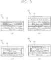
FIG. 5 is a cross-sectional view of a hologram film. -
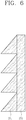
FIG. 6 is a cross-sectional view of a prism sheet. -
FIG. 7 is a conceptual diagram illustrating a vehicle lamp including a plurality of modules. -
FIG. 8 is a conceptual diagram illustrating a vehicle lamp including a light-shielding plate. -
FIG. 9 is a conceptual diagram illustrating a shape of a lighting pattern according to a presence of a light-shielding plate. -
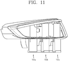
FIGS. 10 and11 are conceptual diagrams illustrating a vehicle lamp not including a housing. -
FIGS. 12 and 13 are conceptual diagrams illustrating a vehicle lamp including a housing. - Description will now be given in detail according to exemplary embodiments disclosed herein, with reference to the accompanying drawings. For the sake of brief description with reference to the drawings, the same or equivalent components may be provided with the same or similar reference numbers, and description thereof will not be repeated. In describing the present disclosure, if a detailed explanation for a related known function or construction is considered to unnecessarily divert the gist of the present disclosure, such explanation has been omitted but would be understood by those skilled in the art. The accompanying drawings are used to help easily understand the technical idea of the present disclosure and it should be understood that the idea of the present disclosure is not limited by the accompanying drawings. The idea of the present disclosure should be construed to extend to any alterations, equivalents and substitutes besides the accompanying drawings.
- It will be understood that although the terms first, second, etc. may be used herein to describe various elements, these elements should not be limited by these terms. These terms are generally only used to distinguish one element from another.
- A singular representation may include a plural representation unless it represents a definitely different meaning from the context.
- Terms such as "include" or "has" are used herein and should be understood that they are intended to indicate an existence of several components, functions or steps, disclosed in the specification, and it is also understood that greater or fewer components, functions, or steps may likewise be utilized.
- A lamp according to the present disclosure has a structure for providing a three-dimensional lighting pattern.
- In order to implement a hologram image, a light ray should be irradiated onto a film in which an interference fringe is stored. When light is irradiated onto the film at which the interference fringe is stored, only waves having the same frequency as when the interference fringe is recorded are reproduced as a stereoscopic image, and other waves pass through the film at which the interference fringe is stored.
- When the hologram image is implemented as a vehicle lamp, light passing through the film at which the interference fringe is stored is light that is substantially lost. A vehicle lamp should have brightness of a predetermined level or more, and since an amount of light lost is a lot when the hologram image is implemented, the hologram image is difficult to have brightness of a predetermined level or more.
- In addition, in the holographic image, distortion of the image may occur depending on a direction viewed by an observer. The vehicle lamp is viewed by an observer from various angles, which causes many limitations in implementing the hologram image in the vehicle lamp.
- Hereinafter, a structure for solving the above-described problem will be described. A lamp according to an embodiment of the present disclosure includes a light source, a hologram film, a reflection plate and a prism sheet. However, the present disclosure is not limited thereto, and the lamp according to the present disclosure may include more components than those described above.
-
FIGS. 3 and4 are conceptual diagrams illustrating a vehicle lamp according to the present disclosure. - A
light source 210 emits light. Thelight source 210 may be formed in various types such as a laser diode, a semiconductor light-emitting device, and an organic light-emitting diode. However, the type of light source is not limited thereto separately. - The
light source 210 is not disposed to face thehologram film 230 but is disposed to face thereflection plate 220. The light emitted from thelight source 210 is not directly toward thehologram film 230, but toward thereflection plate 220. - The
reflection plate 220 is disposed in a tilted state at a predetermined angle with thehologram film 230 such that light emitted from thelight source 210 is reflected and the reflected light is incident on thehologram film 230 obliquely. - Here, the
reflection plate 220 may be composed of a plurality of regions, and at least one of the plurality of regions may have a different reflectance from the remaining region. This is for making an amount of light incident on thehologram film 230 for each region of thehologram film 230 different. - In detail, a distance between each of the plurality of regions included in the
hologram film 230 and thelight source 210 may be different from each other. In this case, an amount of light incident to the region close to thelight source 210 is greater than that to the region far from thelight source 210. Therefore, a phenomenon in which brightness of the image is changed depending on a direction in which the holographic image is viewed. - The present disclosure implements reflectance of the
reflection plate 220 differently for each region such that an amount of light incident on each of the plurality of regions included in thehologram film 230 is uniform. In detail, reflectance of a lower region of thereflection plate 220 that is close to thelight source 210 may be smaller than that of an upper region of thereflection plate 220 that is far from thelight source 210. - In one embodiment, reflectance of the
reflection plate 220 may increase in an upward direction of thereflection plate 220. The present disclosure concentrates light in a region far from thelight source 210 among a plurality of regions included in the hologram film, thereby making an amount of light incident on the hologram film uniform. - Meanwhile, light reflected by the
reflection plate 220 is toward thehologram film 230. Referring toFIG. 5 , thehologram film 230 may have various structures. In detail, referring to (a) ofFIG. 5 , thehologram film 230 may include a substrate, an optically clear adhesive (OCA) layer, a photopolymer layer, and a base film. - The substrate should be made of an optically clear material. The substrate serves to support components constituting the
hologram film 230. The substrate is disposed at one surface facing thereflection plate 220 of the both surfaces of thehologram film 230. Accordingly, the light reflected by thereflection plate 220 is first incident on the substrate. - The OCA layer may be formed on the substrate. The OCA layer is used to bond the substrate and the photopolymer layer. When there are other means for bonding the photopolymer layer and the substrate, the OCA layer is not essential.
- Meanwhile, a photopolymer layer is laminated on the OCA layer. An interference fringe is formed at the photopolymer layer, and a hologram image is formed due to the interference fringe.
- The hologram image is implemented by using only light having a frequency coinciding with the light irradiated when the interference fringe is formed among the light incident on the
hologram film 230. The light having a frequency not coinciding with the light irradiated when the interference fringe is formed passes through thehologram film 230 as it is. - A traveling path of the light having a frequency coinciding with the light irradiated when the interference fringe is formed is changed while passing passes through the photopolymer layer, however the traveling path of the light having a frequency not coinciding with the light irradiated when the interference fringe is formed is not changed and passes through the
hologram film 230 as it is. Accordingly, light emitted from the same light source is dispersed in two different directions. - The light reaching an observer is a light whose traveling path is changed while passing through the
hologram film 230, and the light that does not change the traveling path while passing through thehologram film 230 does not reach the observer. The present disclosure provides a structure that allows the light whose traveling path is not changed reaches the observer while the light passes through thehologram film 230. This will be described later and the remaining structure ofFIG. 5 will be described. - Referring to (a) of
FIG. 5 , a protective layer may be formed on the photopolymer layer. The protective layer serves to protect the photopolymer layer from physical impact. The protective layer may be implemented as various forms. - In detail, referring to (b) of
FIG. 5 , the protective layer may include a first protective layer (Base film) for protecting a physical impact, and a second protective layer (Protection Film or Glass) for protecting the photopolymer layer from moisture, etc. introduced from the outside. The OCA layer may be formed between the first and second protective layers. - On the other hand, referring to (c) of
FIG. 5 , the hologram film may include an encapsulation layer. The encapsulation layer is sealed by covering both an upper side and side surfaces of the photopolymer layer. In this case, the separate OCA layer may not be disposed between the photopolymer layer and the substrate. However, as shown in (d) ofFIG. 5 , the OCA layer may be disposed between the substrate and the photopolymer layer even when the encapsulation layer is used. - Meanwhile, a prism sheet is laminated on the protective layer. The prism sheet allows the light whose traveling path is not changed to reach the observer while passes through the
hologram film 230. - For this, the
prism sheet 231 includes a plurality of concave-convex structures such that the light passing through thehologram film 230 is refracted in one direction. -
FIG. 6 is a conceptual diagram illustrating a cross-section of a prism sheet. - Referring to
FIG. 6 , a plurality of concave-convex structures 231' are formed at theprism sheet 231. Each of the concave-convex structures 231' has an inclined surface that forms a predetermined angle with thehologram film 230. As the light passing through thehologram film 230 is refracted by the inclined surface, the traveling path of the light is changed. - The light whose traveling path is not changed while passing through the
hologram film 230 is refracted by the inclined surface, and proceeds in the same direction as the direction in which the hologram image is formed. Accordingly, brightness of the hologram image may increase. - Meanwhile, an angle between the inclined surface and the
hologram film 230 may be different depending on a position of each of the plurality of concave-convex structures. The traveling path of the light that does not change the traveling path while passing through thehologram film 230 may be different depending on a position at which the light passes. The present disclosure allows the angle formed by the inclined surface and thehologram film 230 to be different depending on a position of the concave-convex structures in order to concentrate the light traveling in various directions to a designated position. - In one embodiment, the angle between the inclined surface and the
hologram film 230 may decrease as toward a lower side of thehologram film 230. - As described above, the present disclosure increases brightness of the hologram image by concentrating the light lost in the direction in which the hologram image is formed while passing through the
hologram film 230. Accordingly, the present disclosure allows the hologram image to have sufficient brightness to be used in a vehicle lamp. - As shown in
FIG. 7 , the above-described vehicle lamp may have a shape in which a plurality ofmodules 200a to 200c are disposed at a predetermined interval. The modules may be disposed in various forms, and thus various types of lighting patterns can be implemented. - Meanwhile, the vehicle lamp according to the present disclosure may further include a light-shielding
plate 240 disposed in a direction opposite to the reflection surface of thereflection plate 220 to be overlapped with thehologram film 230. -
FIG. 8 is a conceptual diagram illustrating a vehicle lamp including a light-shielding plate, andFIG. 9 is a conceptual diagram illustrating a shape of a lighting pattern according to a presence of a light-shielding plate. - Referring to
FIG. 8 , a light-shieldingplate 240 overlapped with thehologram film 230 may be disposed in a rear direction of thereflection plate 220. The presence of the light-shieldingplate 240 may not significantly affect the holographic image, but when the hologram image is not implemented, that is, when no light is emitted from thelight source 210, the light-shieldingplate 240 determines a shape of the lamp. - In detail, referring to (a) of
FIG. 9 , when the light-shieldingplate 240 is not present, the structure disposed inside the lamp is exposed to an outside when the light is not emitted from thelight source 210. This may adversely affect aesthetics of the lamp. When the light-shieldingplate 240 is installed at the rear side of thereflection plate 220 as shown in (b) ofFIG. 9 , even when light is not emitted from thelight source 210, the structure inside the lamp is not exposed to the outside. - Meanwhile, an auxiliary light source for emitting light may be disposed at the light-shielding
plate 240. The auxiliary light source may be used to increase an amount of light in the hologram image when the hologram image is implemented. In this case, the auxiliary light source may be turned on only when the light source is turned on. - The present disclosure improves the aesthetics of the lamp and improves the brightness of the hologram image via the above-described light-shielding
plate 240. - Meanwhile, the present disclosure may further include a housing such that a part of the vehicle lamp is not exposed to the outside.
-
FIGS. 10 and11 are conceptual diagrams illustrating a vehicle lamp not including a housing, andFIGS. 12 and 13 are conceptual diagrams illustrating a vehicle lamp including a housing. - In detail, the
light source 210 irradiating light to thehologram film 230 and thereflection plate 220 should not be overlapped with thehologram film 230. When thehologram film 230 is overlapped with thelight source 210 or thereflection plate 220, since the shape of thelight source 210 or thereflection plate 220 is exposed to the outside of the hologram image, it is difficult to form a complete hologram image. - For this reason, the
light source 210 should be disposed at a position that does not be overlapped with thehologram film 230, which increases a size of the lamp and hinders aesthetics. - Referring to
FIGS. 10 and11 , a light source, a reflection plate and a support means for supporting the hologram film are exposed to the outside to hinder aesthetics of the lamp. - To prevent this, as shown in
FIGS. 12 and 13 , the present disclosure may further include ahousing 300 overlapped with at least one of thelight source 210 and thereflection plate 220 and disposed to surround the lamp. Thehousing 300 prevents thelight source 210, thereflection plate 220, and the support means for supporting thehologram film 230 from being exposed to the outside. Accordingly, the present disclosure improves aesthetics of the vehicle lamp. - According to the present disclosure, since light passing through a hologram film is concentrated in a specific direction, it is possible to implement a three-dimensional lighting pattern and simultaneously, to implement luminance of a predetermined level or more.
- In addition, according to the present disclosure, an amount of light reaching eyes of an observer becomes constant regardless of a direction to look toward a lamp. Accordingly, the present disclosure allows the three-dimensional lighting pattern implemented in the lamp to look constant regardless of a direction of looking toward the lamp.
- It will be apparent to those skilled in the art that the present disclosure may be embodied in other specific forms without departing from the spirit or essential characteristics thereof.
- Therefore, it should also be understood that the above-described embodiments are not limited by any of the details of the foregoing description, unless otherwise specified, but rather should be construed broadly within its scope as defined in the appended claims, The scope of the present disclosure should be determined by rational interpretation of the appended claims, and all changes within the scope of equivalents of the present disclosure are included in the scope of the present disclosure.
Claims (10)
- A lamp comprising:a light source emitting light;a hologram film in which an interference fringe of light is formed;a reflection plate disposed in a tilted state at a predetermined angle with the hologram film such that light emitted from the light source is reflected and the reflected light is incident on the hologram film obliquely; anda prism sheet disposed on one surface of the hologram film and including a plurality of concave-convex structures such that light passing through the hologram film is refracted in one direction;wherein the reflection plate is composed of a plurality of regions and at least one of the plurality of regions has a different reflectance from the remaining region.
- The lamp of claim 1,
wherein the prism sheet is disposed on a surface facing one surface at which light reflected from the reflection plate is incident on both surfaces of the hologram film. - The lamp of claim 1,
wherein each of the plurality of concave-convex structures has an inclined surface that forms a predetermined angle with the hologram film. - The lamp of claim 3,
wherein the angle between the inclined surface and the hologram film is different depending on a position of each of the plurality of concave-convex structures. - The lamp of claim 1,
wherein the hologram film comprises:a substrate made of an optically clear material;an optically clear adhesive (OCA) layer laminated on the substrate;a photopolymer layer laminated on the OCA layer; anda protective layer laminated on the photopolymer layer. - The lamp of claim 5,
wherein an interference fringe is formed on the photopolymer layer such that the hologram pattern is formed by the light transmitting through the hologram film. - The lamp of claim 1,
wherein a reflectance of the reflection plate decreases as toward a lower side of the reflection plate. - The lamp of claim 1, further comprising:
a light-shielding plate disposed in a direction opposite to a reflection surface of the reflection plate and disposed to be overlapped with the hologram film. - The lamp of claim 8,
wherein an auxiliary light source for emitting light is disposed at at least a part of the light-shielding plate. - The lamp of claim 1, further comprising:
a housing overlapped with at least one of the light source and the reflection plate and disposed to surround the lamp.
Applications Claiming Priority (1)
| Application Number | Priority Date | Filing Date | Title |
|---|---|---|---|
| PCT/KR2018/013973 WO2020101070A1 (en) | 2018-11-15 | 2018-11-15 | Vehicle lamp |
Publications (3)
| Publication Number | Publication Date |
|---|---|
| EP3882515A1 true EP3882515A1 (en) | 2021-09-22 |
| EP3882515A4 EP3882515A4 (en) | 2022-07-06 |
| EP3882515B1 EP3882515B1 (en) | 2024-07-24 |
Family
ID=70731564
Family Applications (1)
| Application Number | Title | Priority Date | Filing Date |
|---|---|---|---|
| EP18939925.6A Active EP3882515B1 (en) | 2018-11-15 | 2018-11-15 | Vehicle lamp |
Country Status (4)
| Country | Link |
|---|---|
| EP (1) | EP3882515B1 (en) |
| KR (1) | KR102523591B1 (en) |
| CN (1) | CN113039389B (en) |
| WO (1) | WO2020101070A1 (en) |
Cited By (1)
| Publication number | Priority date | Publication date | Assignee | Title |
|---|---|---|---|---|
| JP2024103190A (en) * | 2023-01-20 | 2024-08-01 | 日産自動車株式会社 | Vehicle lighting fixtures |
Families Citing this family (1)
| Publication number | Priority date | Publication date | Assignee | Title |
|---|---|---|---|---|
| DE102021117908A1 (en) | 2021-07-12 | 2023-01-12 | HELLA GmbH & Co. KGaA | headlights for vehicles |
Family Cites Families (20)
| Publication number | Priority date | Publication date | Assignee | Title |
|---|---|---|---|---|
| JPH03297003A (en) * | 1990-04-16 | 1991-12-27 | Nippondenso Co Ltd | Display device with hologram |
| CN2333872Y (en) * | 1998-09-02 | 1999-08-18 | 广州市光机电工程研究开发中心 | Lamp for automotive vehicle |
| JP2000225889A (en) * | 1999-02-03 | 2000-08-15 | Asahi Glass Co Ltd | Car indicator light |
| JP2003040031A (en) * | 2001-07-31 | 2003-02-13 | Toppan Printing Co Ltd | High-mount stop lamp using optical film |
| DE10215854A1 (en) * | 2002-04-10 | 2003-10-23 | Mekra Lang Gmbh & Co Kg | Flashing light integrated into external mirror, especially for commercial vehicles, has light directing arrangement with mutually offset parallel vertical opaque strips on both sides of light panel |
| JP2006331658A (en) * | 2005-05-23 | 2006-12-07 | Dainippon Printing Co Ltd | Optical member for LED backlight |
| US8169681B2 (en) * | 2006-03-03 | 2012-05-01 | Gentex Corporation | Thin-film coatings, electro-optic elements and assemblies incorporating these elements |
| KR20130021868A (en) * | 2011-08-24 | 2013-03-06 | 엘지디스플레이 주식회사 | Display apparatus for displaying three dimensional picture |
| WO2013159093A1 (en) * | 2012-04-20 | 2013-10-24 | E Ink Corporation | Illumination systems for reflective displays |
| CN203658711U (en) * | 2013-12-31 | 2014-06-18 | 青岛歌尔声学科技有限公司 | Direct type LED backlight module group capable of eliminating lamp shadow and liquid crystal product |
| KR101551079B1 (en) * | 2014-04-10 | 2015-09-08 | 현대자동차주식회사 | Light source module of rear lamp for vehicle |
| KR20150134979A (en) * | 2014-05-23 | 2015-12-02 | 에스엘 주식회사 | Automotive hologram image producing lamp |
| KR20160018917A (en) * | 2014-08-07 | 2016-02-18 | 현대자동차주식회사 | Lamp for vehicle |
| US10023105B2 (en) | 2014-11-07 | 2018-07-17 | Dai Nippon Printing Co., Ltd. | Illumination device and vehicle |
| EP3216650A4 (en) | 2014-11-07 | 2018-06-13 | Dai Nippon Printing Co., Ltd. | Lighting device |
| KR101684003B1 (en) * | 2014-11-25 | 2016-12-08 | 현대자동차주식회사 | Rear lamp for vehicle |
| KR101628561B1 (en) * | 2014-12-08 | 2016-06-08 | 현대자동차주식회사 | Optical device |
| AT517019B1 (en) * | 2015-04-02 | 2017-02-15 | Zkw Group Gmbh | Lighting device and motor vehicle headlights |
| JP6410953B2 (en) * | 2015-09-17 | 2018-10-24 | 古河電気工業株式会社 | LED lighting device and light extraction method of LED lighting device |
| DE102015121697A1 (en) * | 2015-12-14 | 2017-06-14 | Hella Kgaa Hueck & Co. | Lighting device for vehicles |
-
2018
- 2018-11-15 CN CN201880099497.3A patent/CN113039389B/en active Active
- 2018-11-15 EP EP18939925.6A patent/EP3882515B1/en active Active
- 2018-11-15 WO PCT/KR2018/013973 patent/WO2020101070A1/en not_active Ceased
- 2018-11-15 KR KR1020217008782A patent/KR102523591B1/en active Active
Cited By (1)
| Publication number | Priority date | Publication date | Assignee | Title |
|---|---|---|---|---|
| JP2024103190A (en) * | 2023-01-20 | 2024-08-01 | 日産自動車株式会社 | Vehicle lighting fixtures |
Also Published As
| Publication number | Publication date |
|---|---|
| EP3882515B1 (en) | 2024-07-24 |
| WO2020101070A1 (en) | 2020-05-22 |
| EP3882515A4 (en) | 2022-07-06 |
| KR20210042396A (en) | 2021-04-19 |
| KR102523591B1 (en) | 2023-04-19 |
| CN113039389A (en) | 2021-06-25 |
| CN113039389B (en) | 2023-10-24 |
Similar Documents
| Publication | Publication Date | Title |
|---|---|---|
| US7134775B2 (en) | Vehicular headlamp and light-emitting module therefor | |
| US10766404B2 (en) | Lighting device for vehicles | |
| US10317031B2 (en) | Vehicle lamp | |
| JP4258465B2 (en) | Vehicle headlamp unit | |
| US20130027960A1 (en) | Lighting and/or signaling device for a motor vehicle including a surface light source | |
| JP6913589B2 (en) | Vehicle lighting | |
| US20180142858A1 (en) | Headlight with a modular projection module for enhancing illumination intensity | |
| JP2008078086A (en) | Vehicle lighting | |
| JP7483523B2 (en) | Vehicle lighting fixtures | |
| US10718481B2 (en) | Vehicular illumination device | |
| EP3882515B1 (en) | Vehicle lamp | |
| JP2014135158A (en) | Vehicular lighting tool | |
| JP6784083B2 (en) | Vehicle lighting | |
| JP7145644B2 (en) | vehicle lamp | |
| KR20190062732A (en) | Lamp for vehicle | |
| JP6981832B2 (en) | Vehicle lighting | |
| US11124110B2 (en) | Car lamp using semiconductor light emitting device | |
| US20060028815A1 (en) | Light assembly comprising integrated passive and active illumination sources | |
| KR20220120287A (en) | Automotive lamp | |
| KR102546800B1 (en) | Lamp for vehicle | |
| JP2013186988A (en) | Light-emitting device | |
| JP7272842B2 (en) | vehicle lamp | |
| KR20190088378A (en) | Car lamp using semiconductor light emitting device | |
| KR20180037491A (en) | The light source module and vehicle lamp including the same | |
| JP2025032650A (en) | Vehicle lighting fixtures |
Legal Events
| Date | Code | Title | Description |
|---|---|---|---|
| STAA | Information on the status of an ep patent application or granted ep patent |
Free format text: STATUS: THE INTERNATIONAL PUBLICATION HAS BEEN MADE |
|
| PUAI | Public reference made under article 153(3) epc to a published international application that has entered the european phase |
Free format text: ORIGINAL CODE: 0009012 |
|
| STAA | Information on the status of an ep patent application or granted ep patent |
Free format text: STATUS: REQUEST FOR EXAMINATION WAS MADE |
|
| 17P | Request for examination filed |
Effective date: 20210511 |
|
| AK | Designated contracting states |
Kind code of ref document: A1 Designated state(s): AL AT BE BG CH CY CZ DE DK EE ES FI FR GB GR HR HU IE IS IT LI LT LU LV MC MK MT NL NO PL PT RO RS SE SI SK SM TR |
|
| DAV | Request for validation of the european patent (deleted) | ||
| DAX | Request for extension of the european patent (deleted) | ||
| A4 | Supplementary search report drawn up and despatched |
Effective date: 20220603 |
|
| RIC1 | Information provided on ipc code assigned before grant |
Ipc: G03H 1/02 20060101ALN20220530BHEP Ipc: G03H 1/22 20060101ALI20220530BHEP Ipc: G02B 5/32 20060101ALI20220530BHEP Ipc: G02B 5/08 20060101ALI20220530BHEP Ipc: G02B 5/04 20060101ALI20220530BHEP Ipc: F21S 43/50 20180101ALI20220530BHEP Ipc: F21S 43/40 20180101ALI20220530BHEP Ipc: F21S 43/31 20180101ALI20220530BHEP Ipc: F21S 43/20 20180101AFI20220530BHEP |
|
| REG | Reference to a national code |
Ref legal event code: R079 Ipc: F21S0043200000 Ref country code: DE Ref legal event code: R079 Ref document number: 602018072341 Country of ref document: DE Free format text: PREVIOUS MAIN CLASS: F21S0041200000 Ipc: F21S0043200000 |
|
| GRAP | Despatch of communication of intention to grant a patent |
Free format text: ORIGINAL CODE: EPIDOSNIGR1 |
|
| STAA | Information on the status of an ep patent application or granted ep patent |
Free format text: STATUS: GRANT OF PATENT IS INTENDED |
|
| RIC1 | Information provided on ipc code assigned before grant |
Ipc: G03H 1/02 20060101ALN20240424BHEP Ipc: G03H 1/22 20060101ALI20240424BHEP Ipc: G02B 5/32 20060101ALI20240424BHEP Ipc: G02B 5/08 20060101ALI20240424BHEP Ipc: G02B 5/04 20060101ALI20240424BHEP Ipc: F21S 43/50 20180101ALI20240424BHEP Ipc: F21S 43/40 20180101ALI20240424BHEP Ipc: F21S 43/31 20180101ALI20240424BHEP Ipc: F21S 43/20 20180101AFI20240424BHEP |
|
| GRAS | Grant fee paid |
Free format text: ORIGINAL CODE: EPIDOSNIGR3 |
|
| INTG | Intention to grant announced |
Effective date: 20240527 |
|
| GRAA | (expected) grant |
Free format text: ORIGINAL CODE: 0009210 |
|
| STAA | Information on the status of an ep patent application or granted ep patent |
Free format text: STATUS: THE PATENT HAS BEEN GRANTED |
|
| AK | Designated contracting states |
Kind code of ref document: B1 Designated state(s): AL AT BE BG CH CY CZ DE DK EE ES FI FR GB GR HR HU IE IS IT LI LT LU LV MC MK MT NL NO PL PT RO RS SE SI SK SM TR |
|
| REG | Reference to a national code |
Ref country code: GB Ref legal event code: FG4D |
|
| REG | Reference to a national code |
Ref country code: CH Ref legal event code: EP |
|
| REG | Reference to a national code |
Ref country code: DE Ref legal event code: R096 Ref document number: 602018072341 Country of ref document: DE |
|
| REG | Reference to a national code |
Ref country code: IE Ref legal event code: FG4D |
|
| P01 | Opt-out of the competence of the unified patent court (upc) registered |
Free format text: CASE NUMBER: APP_51276/2024 Effective date: 20240911 |
|
| REG | Reference to a national code |
Ref country code: LT Ref legal event code: MG9D |
|
| REG | Reference to a national code |
Ref country code: NL Ref legal event code: MP Effective date: 20240724 |
|
| PG25 | Lapsed in a contracting state [announced via postgrant information from national office to epo] |
Ref country code: PT Free format text: LAPSE BECAUSE OF FAILURE TO SUBMIT A TRANSLATION OF THE DESCRIPTION OR TO PAY THE FEE WITHIN THE PRESCRIBED TIME-LIMIT Effective date: 20241125 |
|
| REG | Reference to a national code |
Ref country code: AT Ref legal event code: MK05 Ref document number: 1706590 Country of ref document: AT Kind code of ref document: T Effective date: 20240724 |
|
| PG25 | Lapsed in a contracting state [announced via postgrant information from national office to epo] |
Ref country code: NL Free format text: LAPSE BECAUSE OF FAILURE TO SUBMIT A TRANSLATION OF THE DESCRIPTION OR TO PAY THE FEE WITHIN THE PRESCRIBED TIME-LIMIT Effective date: 20240724 |
|
| PG25 | Lapsed in a contracting state [announced via postgrant information from national office to epo] |
Ref country code: PT Free format text: LAPSE BECAUSE OF FAILURE TO SUBMIT A TRANSLATION OF THE DESCRIPTION OR TO PAY THE FEE WITHIN THE PRESCRIBED TIME-LIMIT Effective date: 20241125 Ref country code: NL Free format text: LAPSE BECAUSE OF FAILURE TO SUBMIT A TRANSLATION OF THE DESCRIPTION OR TO PAY THE FEE WITHIN THE PRESCRIBED TIME-LIMIT Effective date: 20240724 |
|
| PG25 | Lapsed in a contracting state [announced via postgrant information from national office to epo] |
Ref country code: NO Free format text: LAPSE BECAUSE OF FAILURE TO SUBMIT A TRANSLATION OF THE DESCRIPTION OR TO PAY THE FEE WITHIN THE PRESCRIBED TIME-LIMIT Effective date: 20241024 |
|
| PG25 | Lapsed in a contracting state [announced via postgrant information from national office to epo] |
Ref country code: FI Free format text: LAPSE BECAUSE OF FAILURE TO SUBMIT A TRANSLATION OF THE DESCRIPTION OR TO PAY THE FEE WITHIN THE PRESCRIBED TIME-LIMIT Effective date: 20240724 Ref country code: PL Free format text: LAPSE BECAUSE OF FAILURE TO SUBMIT A TRANSLATION OF THE DESCRIPTION OR TO PAY THE FEE WITHIN THE PRESCRIBED TIME-LIMIT Effective date: 20240724 Ref country code: GR Free format text: LAPSE BECAUSE OF FAILURE TO SUBMIT A TRANSLATION OF THE DESCRIPTION OR TO PAY THE FEE WITHIN THE PRESCRIBED TIME-LIMIT Effective date: 20241025 |
|
| PG25 | Lapsed in a contracting state [announced via postgrant information from national office to epo] |
Ref country code: BG Free format text: LAPSE BECAUSE OF FAILURE TO SUBMIT A TRANSLATION OF THE DESCRIPTION OR TO PAY THE FEE WITHIN THE PRESCRIBED TIME-LIMIT Effective date: 20240724 |
|
| PG25 | Lapsed in a contracting state [announced via postgrant information from national office to epo] |
Ref country code: LV Free format text: LAPSE BECAUSE OF FAILURE TO SUBMIT A TRANSLATION OF THE DESCRIPTION OR TO PAY THE FEE WITHIN THE PRESCRIBED TIME-LIMIT Effective date: 20240724 |
|
| PG25 | Lapsed in a contracting state [announced via postgrant information from national office to epo] |
Ref country code: AT Free format text: LAPSE BECAUSE OF FAILURE TO SUBMIT A TRANSLATION OF THE DESCRIPTION OR TO PAY THE FEE WITHIN THE PRESCRIBED TIME-LIMIT Effective date: 20240724 Ref country code: IS Free format text: LAPSE BECAUSE OF FAILURE TO SUBMIT A TRANSLATION OF THE DESCRIPTION OR TO PAY THE FEE WITHIN THE PRESCRIBED TIME-LIMIT Effective date: 20241124 |
|
| PG25 | Lapsed in a contracting state [announced via postgrant information from national office to epo] |
Ref country code: HR Free format text: LAPSE BECAUSE OF FAILURE TO SUBMIT A TRANSLATION OF THE DESCRIPTION OR TO PAY THE FEE WITHIN THE PRESCRIBED TIME-LIMIT Effective date: 20240724 |
|
| PG25 | Lapsed in a contracting state [announced via postgrant information from national office to epo] |
Ref country code: RS Free format text: LAPSE BECAUSE OF FAILURE TO SUBMIT A TRANSLATION OF THE DESCRIPTION OR TO PAY THE FEE WITHIN THE PRESCRIBED TIME-LIMIT Effective date: 20241024 Ref country code: ES Free format text: LAPSE BECAUSE OF FAILURE TO SUBMIT A TRANSLATION OF THE DESCRIPTION OR TO PAY THE FEE WITHIN THE PRESCRIBED TIME-LIMIT Effective date: 20240724 |
|
| PG25 | Lapsed in a contracting state [announced via postgrant information from national office to epo] |
Ref country code: RS Free format text: LAPSE BECAUSE OF FAILURE TO SUBMIT A TRANSLATION OF THE DESCRIPTION OR TO PAY THE FEE WITHIN THE PRESCRIBED TIME-LIMIT Effective date: 20241024 Ref country code: PL Free format text: LAPSE BECAUSE OF FAILURE TO SUBMIT A TRANSLATION OF THE DESCRIPTION OR TO PAY THE FEE WITHIN THE PRESCRIBED TIME-LIMIT Effective date: 20240724 Ref country code: NO Free format text: LAPSE BECAUSE OF FAILURE TO SUBMIT A TRANSLATION OF THE DESCRIPTION OR TO PAY THE FEE WITHIN THE PRESCRIBED TIME-LIMIT Effective date: 20241024 Ref country code: LV Free format text: LAPSE BECAUSE OF FAILURE TO SUBMIT A TRANSLATION OF THE DESCRIPTION OR TO PAY THE FEE WITHIN THE PRESCRIBED TIME-LIMIT Effective date: 20240724 Ref country code: IS Free format text: LAPSE BECAUSE OF FAILURE TO SUBMIT A TRANSLATION OF THE DESCRIPTION OR TO PAY THE FEE WITHIN THE PRESCRIBED TIME-LIMIT Effective date: 20241124 Ref country code: HR Free format text: LAPSE BECAUSE OF FAILURE TO SUBMIT A TRANSLATION OF THE DESCRIPTION OR TO PAY THE FEE WITHIN THE PRESCRIBED TIME-LIMIT Effective date: 20240724 Ref country code: GR Free format text: LAPSE BECAUSE OF FAILURE TO SUBMIT A TRANSLATION OF THE DESCRIPTION OR TO PAY THE FEE WITHIN THE PRESCRIBED TIME-LIMIT Effective date: 20241025 Ref country code: FI Free format text: LAPSE BECAUSE OF FAILURE TO SUBMIT A TRANSLATION OF THE DESCRIPTION OR TO PAY THE FEE WITHIN THE PRESCRIBED TIME-LIMIT Effective date: 20240724 Ref country code: ES Free format text: LAPSE BECAUSE OF FAILURE TO SUBMIT A TRANSLATION OF THE DESCRIPTION OR TO PAY THE FEE WITHIN THE PRESCRIBED TIME-LIMIT Effective date: 20240724 Ref country code: BG Free format text: LAPSE BECAUSE OF FAILURE TO SUBMIT A TRANSLATION OF THE DESCRIPTION OR TO PAY THE FEE WITHIN THE PRESCRIBED TIME-LIMIT Effective date: 20240724 Ref country code: AT Free format text: LAPSE BECAUSE OF FAILURE TO SUBMIT A TRANSLATION OF THE DESCRIPTION OR TO PAY THE FEE WITHIN THE PRESCRIBED TIME-LIMIT Effective date: 20240724 |
|
| PG25 | Lapsed in a contracting state [announced via postgrant information from national office to epo] |
Ref country code: RO Free format text: LAPSE BECAUSE OF FAILURE TO SUBMIT A TRANSLATION OF THE DESCRIPTION OR TO PAY THE FEE WITHIN THE PRESCRIBED TIME-LIMIT Effective date: 20240724 Ref country code: DK Free format text: LAPSE BECAUSE OF FAILURE TO SUBMIT A TRANSLATION OF THE DESCRIPTION OR TO PAY THE FEE WITHIN THE PRESCRIBED TIME-LIMIT Effective date: 20240724 Ref country code: SM Free format text: LAPSE BECAUSE OF FAILURE TO SUBMIT A TRANSLATION OF THE DESCRIPTION OR TO PAY THE FEE WITHIN THE PRESCRIBED TIME-LIMIT Effective date: 20240724 |
|
| PG25 | Lapsed in a contracting state [announced via postgrant information from national office to epo] |
Ref country code: EE Free format text: LAPSE BECAUSE OF FAILURE TO SUBMIT A TRANSLATION OF THE DESCRIPTION OR TO PAY THE FEE WITHIN THE PRESCRIBED TIME-LIMIT Effective date: 20240724 |
|
| PG25 | Lapsed in a contracting state [announced via postgrant information from national office to epo] |
Ref country code: CZ Free format text: LAPSE BECAUSE OF FAILURE TO SUBMIT A TRANSLATION OF THE DESCRIPTION OR TO PAY THE FEE WITHIN THE PRESCRIBED TIME-LIMIT Effective date: 20240724 |
|
| REG | Reference to a national code |
Ref country code: DE Ref legal event code: R097 Ref document number: 602018072341 Country of ref document: DE |
|
| PG25 | Lapsed in a contracting state [announced via postgrant information from national office to epo] |
Ref country code: SK Free format text: LAPSE BECAUSE OF FAILURE TO SUBMIT A TRANSLATION OF THE DESCRIPTION OR TO PAY THE FEE WITHIN THE PRESCRIBED TIME-LIMIT Effective date: 20240724 Ref country code: IT Free format text: LAPSE BECAUSE OF FAILURE TO SUBMIT A TRANSLATION OF THE DESCRIPTION OR TO PAY THE FEE WITHIN THE PRESCRIBED TIME-LIMIT Effective date: 20240724 |
|
| PLBE | No opposition filed within time limit |
Free format text: ORIGINAL CODE: 0009261 |
|
| STAA | Information on the status of an ep patent application or granted ep patent |
Free format text: STATUS: NO OPPOSITION FILED WITHIN TIME LIMIT |
|
| REG | Reference to a national code |
Ref country code: DE Ref legal event code: R084 Ref document number: 602018072341 Country of ref document: DE |
|
| REG | Reference to a national code |
Ref country code: CH Ref legal event code: PL |
|
| 26N | No opposition filed |
Effective date: 20250425 |
|
| PG25 | Lapsed in a contracting state [announced via postgrant information from national office to epo] |
Ref country code: MC Free format text: LAPSE BECAUSE OF FAILURE TO SUBMIT A TRANSLATION OF THE DESCRIPTION OR TO PAY THE FEE WITHIN THE PRESCRIBED TIME-LIMIT Effective date: 20240724 |
|
| PG25 | Lapsed in a contracting state [announced via postgrant information from national office to epo] |
Ref country code: LU Free format text: LAPSE BECAUSE OF NON-PAYMENT OF DUE FEES Effective date: 20241115 |
|
| REG | Reference to a national code |
Ref country code: CH Ref legal event code: PL |
|
| GBPC | Gb: european patent ceased through non-payment of renewal fee |
Effective date: 20241115 |
|
| PG25 | Lapsed in a contracting state [announced via postgrant information from national office to epo] |
Ref country code: CH Free format text: LAPSE BECAUSE OF NON-PAYMENT OF DUE FEES Effective date: 20241130 |
|
| REG | Reference to a national code |
Ref country code: BE Ref legal event code: MM Effective date: 20241130 |
|
| PG25 | Lapsed in a contracting state [announced via postgrant information from national office to epo] |
Ref country code: SE Free format text: LAPSE BECAUSE OF FAILURE TO SUBMIT A TRANSLATION OF THE DESCRIPTION OR TO PAY THE FEE WITHIN THE PRESCRIBED TIME-LIMIT Effective date: 20240724 |
|
| PG25 | Lapsed in a contracting state [announced via postgrant information from national office to epo] |
Ref country code: GB Free format text: LAPSE BECAUSE OF NON-PAYMENT OF DUE FEES Effective date: 20241115 Ref country code: BE Free format text: LAPSE BECAUSE OF NON-PAYMENT OF DUE FEES Effective date: 20241130 |
|
| PG25 | Lapsed in a contracting state [announced via postgrant information from national office to epo] |
Ref country code: IE Free format text: LAPSE BECAUSE OF NON-PAYMENT OF DUE FEES Effective date: 20241115 |
|
| PGFP | Annual fee paid to national office [announced via postgrant information from national office to epo] |
Ref country code: DE Payment date: 20251118 Year of fee payment: 8 |
|
| PGFP | Annual fee paid to national office [announced via postgrant information from national office to epo] |
Ref country code: FR Payment date: 20251120 Year of fee payment: 8 |
|
| PG25 | Lapsed in a contracting state [announced via postgrant information from national office to epo] |
Ref country code: HU Free format text: LAPSE BECAUSE OF FAILURE TO SUBMIT A TRANSLATION OF THE DESCRIPTION OR TO PAY THE FEE WITHIN THE PRESCRIBED TIME-LIMIT; INVALID AB INITIO Effective date: 20181115 |
|
| PG25 | Lapsed in a contracting state [announced via postgrant information from national office to epo] |
Ref country code: CY Free format text: LAPSE BECAUSE OF FAILURE TO SUBMIT A TRANSLATION OF THE DESCRIPTION OR TO PAY THE FEE WITHIN THE PRESCRIBED TIME-LIMIT; INVALID AB INITIO Effective date: 20181115 |
|
| PG25 | Lapsed in a contracting state [announced via postgrant information from national office to epo] |
Ref country code: TR Free format text: LAPSE BECAUSE OF FAILURE TO SUBMIT A TRANSLATION OF THE DESCRIPTION OR TO PAY THE FEE WITHIN THE PRESCRIBED TIME-LIMIT Effective date: 20240724 |
|
| PG25 | Lapsed in a contracting state [announced via postgrant information from national office to epo] |
Ref country code: SI Free format text: LAPSE BECAUSE OF FAILURE TO SUBMIT A TRANSLATION OF THE DESCRIPTION OR TO PAY THE FEE WITHIN THE PRESCRIBED TIME-LIMIT Effective date: 20240724 |
|
| PG25 | Lapsed in a contracting state [announced via postgrant information from national office to epo] |
Ref country code: LT Free format text: LAPSE BECAUSE OF FAILURE TO SUBMIT A TRANSLATION OF THE DESCRIPTION OR TO PAY THE FEE WITHIN THE PRESCRIBED TIME-LIMIT Effective date: 20240724 |