EP3882467B1 - Gebläse - Google Patents
Gebläse Download PDFInfo
- Publication number
- EP3882467B1 EP3882467B1 EP21161903.6A EP21161903A EP3882467B1 EP 3882467 B1 EP3882467 B1 EP 3882467B1 EP 21161903 A EP21161903 A EP 21161903A EP 3882467 B1 EP3882467 B1 EP 3882467B1
- Authority
- EP
- European Patent Office
- Prior art keywords
- control
- state
- actuating member
- housing
- blower
- Prior art date
- Legal status (The legal status is an assumption and is not a legal conclusion. Google has not performed a legal analysis and makes no representation as to the accuracy of the status listed.)
- Active
Links
Images



Classifications
-
- F—MECHANICAL ENGINEERING; LIGHTING; HEATING; WEAPONS; BLASTING
- F04—POSITIVE - DISPLACEMENT MACHINES FOR LIQUIDS; PUMPS FOR LIQUIDS OR ELASTIC FLUIDS
- F04D—NON-POSITIVE-DISPLACEMENT PUMPS
- F04D27/00—Control, e.g. regulation, of pumps, pumping installations or pumping systems specially adapted for elastic fluids
- F04D27/004—Control, e.g. regulation, of pumps, pumping installations or pumping systems specially adapted for elastic fluids by varying driving speed
-
- F—MECHANICAL ENGINEERING; LIGHTING; HEATING; WEAPONS; BLASTING
- F04—POSITIVE - DISPLACEMENT MACHINES FOR LIQUIDS; PUMPS FOR LIQUIDS OR ELASTIC FLUIDS
- F04D—NON-POSITIVE-DISPLACEMENT PUMPS
- F04D25/00—Pumping installations or systems
- F04D25/02—Units comprising pumps and their driving means
- F04D25/06—Units comprising pumps and their driving means the pump being electrically driven
- F04D25/0673—Battery powered
-
- E—FIXED CONSTRUCTIONS
- E01—CONSTRUCTION OF ROADS, RAILWAYS, OR BRIDGES
- E01H—STREET CLEANING; CLEANING OF PERMANENT WAYS; CLEANING BEACHES; DISPERSING OR PREVENTING FOG IN GENERAL CLEANING STREET OR RAILWAY FURNITURE OR TUNNEL WALLS
- E01H1/00—Removing undesirable matter from roads or like surfaces, with or without moistening of the surface
- E01H1/08—Pneumatically dislodging or taking-up undesirable matter or small objects; Drying by heat only or by streams of gas; Cleaning by projecting abrasive particles
- E01H1/0809—Loosening or dislodging by blowing ; Drying by means of gas streams
-
- A—HUMAN NECESSITIES
- A01—AGRICULTURE; FORESTRY; ANIMAL HUSBANDRY; HUNTING; TRAPPING; FISHING
- A01G—HORTICULTURE; CULTIVATION OF VEGETABLES, FLOWERS, RICE, FRUIT, VINES, HOPS OR SEAWEED; FORESTRY; WATERING
- A01G20/00—Cultivation of turf, lawn or the like; Apparatus or methods therefor
- A01G20/40—Apparatus for cleaning the lawn or grass surface
- A01G20/43—Apparatus for cleaning the lawn or grass surface for sweeping, collecting or disintegrating lawn debris
- A01G20/47—Vacuum or blower devices
-
- B—PERFORMING OPERATIONS; TRANSPORTING
- B08—CLEANING
- B08B—CLEANING IN GENERAL; PREVENTION OF FOULING IN GENERAL
- B08B13/00—Accessories or details of general applicability for machines or apparatus for cleaning
-
- B—PERFORMING OPERATIONS; TRANSPORTING
- B08—CLEANING
- B08B—CLEANING IN GENERAL; PREVENTION OF FOULING IN GENERAL
- B08B5/00—Cleaning by methods involving the use of air flow or gas flow
- B08B5/02—Cleaning by the force of jets, e.g. blowing-out cavities
-
- F—MECHANICAL ENGINEERING; LIGHTING; HEATING; WEAPONS; BLASTING
- F04—POSITIVE - DISPLACEMENT MACHINES FOR LIQUIDS; PUMPS FOR LIQUIDS OR ELASTIC FLUIDS
- F04D—NON-POSITIVE-DISPLACEMENT PUMPS
- F04D19/00—Axial-flow pumps
- F04D19/002—Axial flow fans
-
- F—MECHANICAL ENGINEERING; LIGHTING; HEATING; WEAPONS; BLASTING
- F04—POSITIVE - DISPLACEMENT MACHINES FOR LIQUIDS; PUMPS FOR LIQUIDS OR ELASTIC FLUIDS
- F04D—NON-POSITIVE-DISPLACEMENT PUMPS
- F04D25/00—Pumping installations or systems
- F04D25/02—Units comprising pumps and their driving means
- F04D25/06—Units comprising pumps and their driving means the pump being electrically driven
-
- F—MECHANICAL ENGINEERING; LIGHTING; HEATING; WEAPONS; BLASTING
- F04—POSITIVE - DISPLACEMENT MACHINES FOR LIQUIDS; PUMPS FOR LIQUIDS OR ELASTIC FLUIDS
- F04D—NON-POSITIVE-DISPLACEMENT PUMPS
- F04D29/00—Details, component parts, or accessories
- F04D29/26—Rotors specially for elastic fluids
- F04D29/32—Rotors specially for elastic fluids for axial flow pumps
- F04D29/325—Rotors specially for elastic fluids for axial flow pumps for axial flow fans
-
- F—MECHANICAL ENGINEERING; LIGHTING; HEATING; WEAPONS; BLASTING
- F04—POSITIVE - DISPLACEMENT MACHINES FOR LIQUIDS; PUMPS FOR LIQUIDS OR ELASTIC FLUIDS
- F04D—NON-POSITIVE-DISPLACEMENT PUMPS
- F04D29/00—Details, component parts, or accessories
- F04D29/40—Casings; Connections of working fluid
- F04D29/403—Casings; Connections of working fluid especially adapted for elastic fluid pumps
-
- Y—GENERAL TAGGING OF NEW TECHNOLOGICAL DEVELOPMENTS; GENERAL TAGGING OF CROSS-SECTIONAL TECHNOLOGIES SPANNING OVER SEVERAL SECTIONS OF THE IPC; TECHNICAL SUBJECTS COVERED BY FORMER USPC CROSS-REFERENCE ART COLLECTIONS [XRACs] AND DIGESTS
- Y02—TECHNOLOGIES OR APPLICATIONS FOR MITIGATION OR ADAPTATION AGAINST CLIMATE CHANGE
- Y02B—CLIMATE CHANGE MITIGATION TECHNOLOGIES RELATED TO BUILDINGS, e.g. HOUSING, HOUSE APPLIANCES OR RELATED END-USER APPLICATIONS
- Y02B30/00—Energy efficient heating, ventilation or air conditioning [HVAC]
- Y02B30/70—Efficient control or regulation technologies, e.g. for control of refrigerant flow, motor or heating
Definitions
- the invention relates to a gardening tool, in particular to a blower.
- a blower is a commonly used gardening tool that helps users clean up fallen leaves and dust in the garden.
- the blower is equipped with operating members for the user to operate to regulate speed and boost speed (the motor running at the maximum rotational speed), and at the same time the blower is also provided with a start switch to start the motor.
- speed and boost speed the motor running at the maximum rotational speed
- the blower is also provided with a start switch to start the motor.
- the start switch, the speed regulator and the accelerator are separately provided. The user needs to operate the start switch first, and then operate the speed regulator or accelerator to meet the user's needs. Said operations are not conducive to the continuity of user operations. Moreover, such settings increase the user's operation steps, which is very inconvenient for the user's operation.
- the start switch when the start switch is accidentally triggered, the motor is likely to run at the maximum rotational speed, resulting in the maximum air output volume of the blower, bringing stones and branches, etc. up to accidentally injure people or objects, causing safety hazards
- a blower according to claim 1 is provided.
- the motor stops running; the control member forms a rotatable connection with the housing about a second rotation axis; when the actuating member is not driven by an external force, the initial state, the first control state and the second control state respectively correspond to different rotation angles of the control member relative to the housing.
- the actuating member is configured to rotate with respect to the housing about a first rotation axis.
- control member is configured to rotate with respect to the housing about a second rotation axis.
- the actuating member is at least partially disposed in the housing, the actuating member is configured to rotate about a first rotation axis, and the actuating member is configured to rotate to the on state from the off state with respect to the control member.
- control member is at least partially disposed in the housing, the control member forms a rotatable connection with the housing about a second rotation axis, and the control member is configured to abut against the switch when the control member rotates about the second rotation axis to the second control state.
- the blower further includes a stopper for preventing the actuating member from crossing the predefined limit position.
- the blower further includes a handle portion fixedly connected or integrally formed with the housing, the handle portion includes a first housing and a second housing, a handle space is formed between the first housing and the second housing, the actuating member is mounted to the handle portion, the actuating member is at least partially accommodated in the handle space, and the stopper is arranged in the handle space and is fixedly connected or integrally formed with the handle portion.
- the switch includes a push rod that can be triggered by the control member and the actuating member, the actuating member includes a drive portion engaging with the push rod; when the actuating member rotates about the first rotation axis to enter the on state, the drive portion drives the push rod to move in a first straight line direction.
- control member includes a first protrusion
- actuating member further includes a sliding portion; when the control member rotates about the second rotation axis to enter the first control state from the initial state, the first protrusion drives the sliding portion of the actuating member to make the actuating member to rotate.
- control member further includes a second protrusion
- the actuating member is provided with a through hole; when the control member rotates to the second control state from the first control state, the second protrusion passes through the through hole to drive the push rod to move along the first straight line direction.
- the speed regulator assembly further includes an elastic member mounted to the housing, and the elastic member is configured to apply a force to the control member to restore the control member from the second control state to the first control state.
- control member includes a third protrusion fixedly connected or integrally formed with the control member
- elastic member includes a free end
- the housing is provided with a supporting portion that restricts the free end from moving freely, and the free end is in contact with the third protrusion when the control member is in the second control state.
- the control member in the first control state, is capable of holding at a plurality of speed control positions, each of the plurality of speed control positions corresponds to a different intermediate speed of the motor, and one of the plurality of speed control position corresponding to a maximum intermediate speed of the motor is the maximum speed control position when the control member is in the first control state.
- the speed regulator assembly further includes a locking device; when the control member is in the speed control position, the locking device is configured to apply a force to prevent the control member from moving.
- the speed regulator assembly further includes an elastic member mounted to the housing, the elastic member is configured to apply a force to the control member to restore the control member from the second control state to maximum speed control position.
- control member when the control member is in the second control state, the control member is configured to rotate with respect to the actuating member about the second rotation axis.
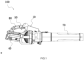
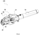
- FIG. 1 shows a blower 100 for blowing away leaves and garbage on the ground or eaves.
- the blower 100 in this embodiment is specifically a handheld axial blower.
- the blower 100 may also be other types of blowers, such as a backpack blower.
- the blower includes: a housing 10, a blow tube 70, a prime mover, a fan 20, a speed regulator assembly 50 and a power source 40.
- the housing 10 is formed with an accommodating space, and the accommodating space is used for accommodating various parts inside the blower. That is, the prime mover, the fan 20 and the speed regulator assembly 50 are at least partially arranged inside the accommodating space.
- the housing 10 is at least formed with a handle portion 80, and the handle portion 80 is used for the user to hold.
- the blow tube 70 is formed with an air duct for air circulation, and the blow tube 70 is detachably connected to the housing 10.
- the prime mover is a motor 30; the motor 30 is enabled to rotate about a first axis 104; the motor 30 includes a motor shaft 31 extending along the first axis 104.
- the fan 20 is connected to the motor 30.
- the fan 20 and the motor shaft 31 form a synchronous rotation, that is, the motor shaft 31 can drive the fan 20 to rotate to generate air flow, which is eventually blown out from the blow tube 70.
- the fan 20 may be directly driven by the motor 30, or the two may be connected through a transmission device.
- the power source 40 provides energy source for the blower 100.
- the power source 40 may be AC or DC.
- the power source 40 is a battery pack that is engaged with the housing 10. It can be understood that, when not in use, the blower 100 may not include a power source. Further, the power source 40, not limited to a battery pack, may be an external DC power supply.
- the speed regulator assembly 50 is installed on the housing 10; specifically, the speed regulator assembly 50 is installed on the handle portion, so that when the user holds the handle portion 80, the speed regulator assembly 50 is relatively easily to operate, thereby facilitating the drive of the motor 30.
- the speed regulator assembly 50 includes a switch 51, a control member 52, and an actuating member 53.
- the switch 51 is coupled with the motor 30 to control the operation of the motor 30; particularly, the switch 51 can control the motor 30 to rotate at any rotational speed between stop and the maximum rotational speed.
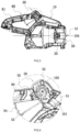
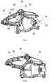
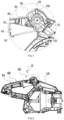
- the actuating member 53 is rotatably connected with the housing 10 and can control the switch 51. During rotation, the actuating member 53 at least includes an off state and an on state, that is, the actuating member 53 is movable between the off state and the on state. As shown in FIGS. 3-4 , the actuating member 53 is in the off state. When the actuating member 53 is in the off state, the motor 30 stops rotating. As shown in FIGS. 6-7 , the actuating member 53 is in the on state. When the actuating member 53 is in the on state, the motor 30 can rotate at a certain speed. At this time, the rotational speed of the motor 30 is lower than the maximum rotational speed that the motor 30 can reach.
- the actuating member 53 can move to a predefined limit position in its on state, and when the actuating member 53 moves to the predefined limit position, the motor 30 can run at a predefined rotational speed, wherein the predefined rotational speed is lower than the maximum rotational speed that the motor 30 can reach. That is to say, when the actuating member 53 moves between the off state and the on state, the rotational speed of the motor 30 is kept to be lower than the maximum rotational speed that the motor 30 can reach.
- the predefined limit position here refers to the maximum angle that the actuating member 53 can rotate during rotation.
- the control member 52 is rotatably connected with the housing 10 to control the switch 51.
- the control member 52 at least includes a second control state, a first control state and an initial state.
- the control member 52 is in the initial state.
- the control member 52 is in the second control state.
- the motor 30 can run at the maximum rotational speed, the air output volume of the blow tube 70 reaches the maximum, and the wind is also the strongest.
- the control member 52 is in the first control state.
- the motor 30 can run at an intermediate speed lower than the maximum rotational speed.
- the control member 52 can drive the actuating member 53 to move from the off state to the on state.
- the actuating member 53 cannot cross the predefined limit position, that is, the actuating member 53 can only rotate up to the predefined limit position.
- the user controls the rotational speed of the motor 30 by operating the actuating member 53 or by operating the control member 52. For things that cannot be blown away, such as tree branches, pebbles and the like, drive the control member 52 to the second control state.
- running the motor 30 of the blower 100 at the maximum rotational speed for a long time is prone to shorten the power supply time of the battery pack, which impacts the working hours of the blower 100, thus running the motor 30 of the blower 100 at the maximum rotational speed is a usage mode that generally only lasts for a short time, while the actuating member 53 can keep the blower 100 in a normal blowing state. Even if the user drives the actuating member 53 to the predefined limit position, it is still in the normal blowing state, and there is no need to control the force acting upon the actuating member 53. With this setting, it is easy for the user to control the rotational speed of the motor 30 of the blower 100 based on different situations, improving user convenience.
- the initial state refers to the original position of the control member 52 (as shown in FIG. 4 ).
- the original position of the control member 52 is often not fixed for installation or operation reasons, which does not matter. As long as the position of the control member 52 is not affected by any external force, it can be regarded as the original position. Therefore, when the actuating member 53 is in the off state, as long as the control member 52 is in the original position and the motor 30 is not running, it can be said that the control member 52 is in the initial state. It should be noted here that when the blower 100 is in a working state and the control member 52 is in the initial state, the operating state of the motor 30 is not limited.
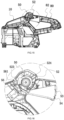
- control member 52 being in the second control state refers to the position of the control member 52 when the motor 30 is running at the maximum rotational speed or the maximum power (as shown in FIG. 9 ).
- the second control state is not limited to some certain position, as long as the rotational speed or the power of the motor 30 reaches its maximum, the position can be referred as the second control state.
- the control member 52 being in the first control state refers to the position of the control member 52 when the motor 30 is running at a speed lower than the maximum rotational speed or at a power lower than the maximum power.
- the off state of the actuating member 53 refers to a position of the actuating member 53 when the power source 40 stops supplying power to the motor 30(as shown in FIG.
- the on state of the actuating member 53 refers to a position of the actuating member 53 when the actuating member 53 is moved by force to make the power source 40 energize the motor 30, and that the motor 30 is running. Similarly, it should be understood that the position here is not limited to one place, as long as the above conditions are met. With the aforementioned settings, on the one hand, even if the actuating member 53 of the blower 100 is triggered accidentally, it can only trigger the normal blowing state, so as to avoid the situation that the blower 100 directly makes the motor 30 reach the maximum rotational speed and the maximum air output volume after the blower 100 is triggered by mistake.
- the motor 30 of the blower 100 running at the maximum rotational speed is not the normal working state of the blower 100.
- the normal blowing function can meet the requirements of normal operations, and the air output volume of the blower 100 can be adjusted according to different working conditions. Only when encountering stones or large branches, does the motor of the blower 100 need to run at the maximum rotational speed.
- the handle portion 80 includes a first housing 81 and a second housing 82, and a handle space is formed between the first housing 81 and the second housing 82.
- the actuating member 53 is mounted to the handle portion 80, wherein the actuating member 53 is movable within the handle space, the actuating member 53 is rotatably connected to the handle portion 80 and can rotate about a first rotation axis 101; the actuating member 53 is pressed against the switch 51, and is enabled to apply a driving force to trigger the switch 51, at which time the actuating member 53 can rotate with respect to the control member 52.
- the actuating member 53 is a trigger 54, and the user operates the trigger 54 to make the trigger 54 rotate about the first rotation axis 101 in a first direction A; when the trigger 54 rotates between the off state and the on state, without being driven by an external force, the control member 52 stays in the initial position.
- the switch 51 is specifically a signal switch.
- the speed regulator assembly 50 also includes a restoring spring 55 for resetting the trigger 54.
- the restoring spring 55 is provided within the handle space, one end of the restoring spring 55 is pressed against the first housing 81 or the second housing 82, while the other end of the restoring spring 55 is mounted to the trigger 54.
- the trigger 54 When the trigger 54 is driven by an external force to rotate, the trigger 54 will compress the restoring spring 55 to make it elastically deformed.
- the trigger 54 loses the drive of the external force, under the elastic force, the trigger 54 will immediately rotate about the first rotation axis 101 along a second direction B to restore the off state.
- the trigger 54 has a plurality of start speed control positions; each start speed control position corresponds to a different rotational speed of the motor 30.
- the start speed control position corresponding to the maximum rotational speed of the motor 30 is defined as the maximum start speed control position
- the maximum start speed control position is the predefined limit position, which corresponds to the aforementioned predefined rotational speed.
- the movement of the trigger 54 from the off state to the maximum start speed control position corresponds to a stepless speed change of the motor 30 with a constant speed increase.
- the housing 10 includes a handle portion and a body portion, and the speed regulator assembly 50 is at least partially disposed inside the handle portion, wherein the handle portion is removably fixed to the body portion.
- the handle portion and the body portion may be directly connected by means of screw connection, buckle connection, etc., or may be indirectly connected by means of an intermediate device, wherein the handle portion is fixedly mounted to the intermediate device and the intermediate device is fixedly installed on the body portion.
- the handle includes a first handle housing and a second handle housing.
- the first handle housing and the second handle housing may be connected by screw connection, snap connection, etc., and one of the first handle housing and the second handle housing may be disassembled separately, that is, the user can disassemble the first handle housing or the second handle housing by himself for the convenience of inspection, repair or maintenance.
- the control member 52 is at least partially disposed in the handle space.
- the control member 52 is rotatably connected to the handle portion 80 and can rotate about a second rotation axis 102.
- the control member 52 is disposed adjacent to the switch 51.
- the control member 52 can abut against the switch 51 during the process of rotation, and can apply a driving force to the switch 51 to drive the switch 51.
- the control member 52 is driven by an external force and rotates in a third direction C about the second rotation axis 102 so as to contact the switch 51.
- the control member 52 restores, that is, the control member 52 rotates in a fourth direction D about the second rotation axis 102 and returns to the first control state.
- the user continues to apply an external force to make the control member 52 continue to rotate in the fourth direction D about the second rotation axis 102, and finally return to the initial position.
- the first control state is between the initial state and the second control state.
- the control member 52 in the first control state, is capable of holding at a plurality of speed control positions, and each of the plurality of speed control positions corresponds to a different intermediate speed of the motor 30.
- the plurality of speed control positions one of the plurality of speed control positions corresponding to a maximum intermediate speed of the motor 30 is defined as the maximum speed control position when the control member 52 is in the first control state.
- the rotation of the control member 52 from the initial state to the maximum speed control position corresponds to a stepless speed change of the motor 30 with a maintainable constant speed increase.
- the speed regulator assembly 50 also includes a locking device 57.
- the locking device 57 When the control member 52 is in the speed control position, the locking device 57 is configured to apply a force to the control member 52 to prevent the control member 52 from moving. i.e., the locking device 57 can lock the position of the control member 52 after the control member 52 is rotated to the speed control position, that is, at this time, the user does not need to apply any force to the control member 52, and the position of the control member 52 will not move.
- the motor 30 will keep running at the speed corresponding to the speed control position.
- the control member 52 receives a frictional force in a tangential direction opposite to the direction of rotation from the trigger 54. Under no other external force, the control member 52 will, under the action of the frictional force, restore to the initial position.
- the locking device 57 applies a static frictional force with equal strength and opposite direction to said frictional force on the control member 52 such that the control member 52 does not shift.
- the locking device 57 is a wave washer mounted between the housing 10 and control member 52; the control member 52 contacts the wave washer.
- the control member 52 squeezes the wave washer to make it elastically deformed.
- the wave washer exerts a reverse force on the control member 52.
- the reverse force is perpendicular to the movement plane of the control member 52, thereby generating a frictional force parallel to the movement direction of the control member 52.
- the speed regulator assembly 50 further includes an elastic member 56, which is mounted to the housing 10.
- the control member 52 includes a third protrusion 523.
- the elastic member 56 has at least one free end 561, and the housing is provided with a supporting portion 11 at least partially in contact with the free end 561.
- the control member 52 when the user drives the control member 52 to the second control state, the third protrusion 523 of the control member 52 contacts the free end 561 and compresses the free end 561 to make the elastic member 56 deformed; when the user revokes the external force, driven by the elastic force of the elastic member 56 and under no other external force, the control member 52 is made to rotate about the second rotation axis 102 in the fourth direction D to enter the first control state or the initial state.
- the control member 52 rebounds to the maximum speed control position, that is, the rebound inertia of the control member 52 is less than the frictional force of the locking device 57, so that the control member 52 only rebounds to the corresponding maximum speed control position.
- the elastic member 56 is a torsion spring, and the torsion spring has at least one free end 561, and the free end 561 is at least partially in contact with the support portion 11.
- the third protrusion 523 is fixedly connected or integrally formed with the control member 52.
- the control member 52 can drive the actuating member 53 to move from the off state to the on state.
- the user can drive the actuating member 53 to rotate about the second rotation axis 102 to the maximum start speed control position; at this time, the control member 52 is in contact with the switch 51 whereas the actuating member 53 is not in contact with the switch 51.
- the control member 52 will keep stationary. At this time, the actuating member 53 is in contact with the switch 51 whereas the control member 52 is not in contact with the switch 51. That is, the actuating member 53 moves together with the control member 52.
- the above configurations facilitate the user to control the air output volume of the blower 100 according to different situations.
- the two different speed control modes of the actuating member 53 and the control member 52 can cater to users' different operating habits, which is more humane and more ergonomic.
- the blower 100 further includes a stopper 60, and the stopper 60 is arranged on the rotation path of the actuating member 53.
- the actuating member 53 rotates about the first rotation axis 101
- the actuating member 53 can rotate to the predefined limit position.
- the motor 30 can run at a predefined rotational speed lower than the maximum rotational speed.
- the stopper 60 is arranged on the rotation path of the actuating member 53, and the stopper 60 prevents the actuating member 53 from crossing the predefined limit position when being pressed.
- the actuating member 53 is driven to rotate from the off position to the predefined limit position: the greater angle the actuating member 53 rotates, the greater the rotational speed of the motor 30.
- the stopper 60 is fixedly connected or integrally formed with the housing 10. Specifically, the stopper 60 is fixedly connected or integrally formed with the first housing 81 or the second housing 82. Of course, a plurality of stoppers 60 may also be provided on the first housing 81 or the second housing 82 to increase structural strength.
- the stopper 60 includes a stop surface 61, and the actuating member 53 has a contact surface 535. The user operates the actuating member 53; the actuating member 53 rotates under force to make the contact surface 535 in contact with the stop surface 61. In other words, once the contact surface 535 contacts the stop surface 61, the actuating member 53 stops rotating.
- the above configurations enable the user to control the air output volume of the blower 100 when the user operates the actuating member 53 with only one hand, and even if the user presses the actuating member 53 to the predefined limit position, the rotational speed of the motor 30 of the blower 100 is still at a relatively low state. In this way, the user does not need to deliberately control the pressing force of the actuating member 53 during operation, which makes the user more comfortable.
- the switch 51 further includes a triggerable push rod 511, and the push rod 511 extends substantially along a first straight line direction 103.
- the actuating member 53 includes a drive portion 531, wherein the drive portion 531 of the actuating member 53 abuts against the push rod 511 of the switch 51, when the user applies an external force to the actuating member 53, the drive portion 531 drives the pushing rod 511 to move in the first straight line direction 103 to start the motor 30.
- the actuating member 53 may have multiple speed control positions during the process of rotation, and each speed control position corresponds to a different speed of the motor 30.
- the driving portion 531 of the trigger 54 drives the push rod 511 to move along the first straight line direction 103.
- the rotational speed of the motor 30 increases with the angle of rotation of the actuating member 53.
- the trigger 54 rebounds by the elastic force of the restoring spring 55, the push rod 511 restores after losing the drive of the external force, and the motor 30 stops.
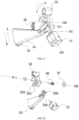
- the control member 52 includes a first protrusion 521, a second protrusion 522, and an operating portion 524;
- the trigger 54 includes a sliding portion 532.
- the first protrusion 521 of the control member 52 contacts the sliding portion 532 of the trigger 54 and drives the sliding portion 532 to make the trigger 54 rotate about the first rotation axis 101, so that the driving portion 531 of the trigger 54 drives the push rod 511 to move along the first straight line direction 103 to activate the motor 30.
- the first protrusion 521 and the control member 52 are fixedly connected or integrally formed, wherein the fixed connection may be direct or indirect.
- first protrusion 521 and the control member 52 may be directly fixed by interference connection, welding, etc.; or, the first protrusion 521 and the control member 52 may be connected through a transmission member; of course, the first protrusion 521 and the control member 52 may be integrally formed.
- the specific connection between the first protrusion 521 and the control member 52 is not limited herein.
- the second protrusion 522 and the first protrusion 521 are fixedly connected or integrally formed.
- the trigger 54 also includes a contact portion 533, and a through hole 534 is provided on the contact portion 533, wherein, during the process that the control member 52 rotates about the second rotation axis 102, the second protrusion 522 can at least partially pass through the through hole 534; at this time, the second protrusion 522 contacts the push rod 511 and drives the push rod 511 to move along the first straight line direction 103 until the control member 52 is in the second control state.
- the control member 52 rotates in the third direction C; the first protrusion 521 drives the sliding portion 532 of the actuating member 53; the actuating member 53 rotates in the first direction A under a force; the actuating member 53 compresses the restoring spring 55, the drive portion 531 of the actuating member 53 drives the push rod 511, and the motor 30 starts.
- the rotational speed of the motor 30 increases, and the actuating member 53 rotates until the contact surface 535 contacts the stop surface 61; at this time, the actuating member 53 stops moving because of the restriction from the stopper 60, whereas the control member 52 continues to rotate in the third direction C under a force; the first protrusion 521 continues to exert a force upon the sliding portion 532; after passing through the through hole 534, the second protrusion 522 continues to push the push rod 511 to move along the first straight line direction 103, so that the motor 30 can run at the maximum rotational speed.
- the elastic member 56 rebounds to make the control member 52 restore to the maximum speed control position, changing the rotational speed of the motor 30 from the maximum rotational speed to the rotational speed of the motor 30 corresponding to the maximum speed control position of the control member 52. That means, in different working conditions, users can choose different air output volume according to the actual situation. For example, when using the blower 100 to blow fallen leaves and dust, upon encountering branches, pebbles, etc. difficult to blow, the control member 52 can be driven to the second control state. When the branches, pebbles, etc. are blown into predefined areas, the control member 52 can be released to restore to the first control state to continue working.
- the first protrusion 521 is disposed between the second protrusion 522 and the third protrusion 523; the third protrusion 523 is disposed on a side away from the push rod 511.
- the first protrusion 521 has a first convex surface, and the first convex surface is substantially arc-shaped.
- the third protrusion 533 extends substantially along the direction of the second rotation axis 102.
Landscapes
- Engineering & Computer Science (AREA)
- Mechanical Engineering (AREA)
- General Engineering & Computer Science (AREA)
- Life Sciences & Earth Sciences (AREA)
- Environmental Sciences (AREA)
- Architecture (AREA)
- Civil Engineering (AREA)
- Structural Engineering (AREA)
- Structures Of Non-Positive Displacement Pumps (AREA)
- Cleaning And Drying Hair (AREA)
Claims (14)
- Gebläse (100), das Folgendes umfasst:ein Gehäuse (10);einen im Gehäuse angeordneten Ventilator (20);einen im Gehäuse angeordneten und mit dem Ventilator verbundenen Motor (30); undeine Drehzahlreglerbaugruppe (50), die so konfiguriert ist, dass sie die Drehzahl des Motors steuert, wobei die Drehzahlreglerbaugruppe einen Schalter (51), der mit dem Motor gekoppelt ist, um den Betrieb des Motors zu steuern, ein Steuerelement (52), das drehbar mit dem Gehäuse verbunden ist, um den Schalter zu steuern, und ein Betätigungselement (53) umfasst, das drehbar mit dem Gehäuse verbunden ist, um den Schalter zu steuern, wobei das Betätigungselement so ausgelegt ist, dass es sich zwischen einem Aus-Zustand und einem Ein-Zustand bewegt,das Betätigungselement in der Lage ist, sich im eingeschalteten Zustand in eine vordefinierte Endposition zu bewegen, die Drehzahl des Motors, die der vordefinierten Endposition entspricht, eine vordefinierte Drehzahl ist, der Motor aufhört zu laufen, wenn das Betätigungselement im ausgeschalteten Zustand ist, und der Motor sich dreht, wenn das Betätigungselement im eingeschalteten Zustand ist; undwobei das Steuerelement einen ersten Steuerzustand und einen zweiten Steuerzustand umfasst, wobei der Motor so konfiguriert ist, dass er mit einer maximalen Drehzahl läuft, die größer als die vordefinierte Drehzahl ist, wenn sich das Steuerelement im zweiten Steuerzustand befindet,und der Motor so ausgelegt ist, dass er mit einer Zwischendrehzahl läuft, die niedriger als die maximale Drehzahl ist, wenn sich das Steuerelement im ersten Steuerzustand befindet, das Steuerelement so konfiguriert ist, dass es das Betätigungselement antreibt, um sich während des Bewegungsprozesses von einem Ausgangszustand in den ersten Steuerzustand vom Aus-Zustand in den Ein-Zustand zu bewegen,das Betätigungselement und das Steuerelement von einem Benutzer betätigt werden können, um die Drehgeschwindigkeit des Motors zu steuern;das Betätigungselement so konfiguriert ist, dass es sich zu der vordefinierten Grenzposition bewegt, die durch das Steuerelement angetrieben wird, wobei sich das Steuerelement im ersten Steuerzustand befindet, wenn das Betätigungselement die vordefinierte Grenzposition erreicht, dadurch gekennzeichnet, dass das Betätigungselement so konfiguriert ist, dass es die vordefinierte Grenzposition nicht überschreitet, wenn das Steuerelement vom ersten Steuerzustand in den zweiten Steuerzustand wechselt.
- Gebläse nach Anspruch 1, wobei, wenn sich das Betätigungselement im Aus-Zustand und das Steuerelement im Anfangszustand befindet, der Motor nicht mehr läuft; das Steuerelement eine drehbare Verbindung mit dem Gehäuse um eine zweite Drehachse (102) bildet; wenn das Betätigungselement nicht durch eine externe Kraft angetrieben wird, der Anfangszustand, der erste Steuerzustand und der zweite Steuerzustand jeweils unterschiedlichen Drehwinkeln des Steuerelements relativ zum Gehäuse entsprechen.
- Gebläse nach Anspruch 1, wobei das Betätigungselement so konfiguriert ist, dass es sich in Bezug auf das Gehäuse um eine erste Drehachse (101) dreht.
- Gebläse nach Anspruch 1, wobei das Steuerelement so konfiguriert ist, dass es sich in Bezug auf das Gehäuse um eine zweite Drehachse (102) dreht.
- Gebläse nach Anspruch 1, wobei das Betätigungselement zumindest teilweise im Gehäuse angeordnet ist, das Betätigungselement so konfiguriert ist, dass es sich um eine erste Drehachse (101) dreht, und das Betätigungselement so konfiguriert ist, dass es sich in Bezug auf das Steuerelement aus dem Aus-Zustand in den Ein-Zustand dreht.
- Gebläse nach Anspruch 5, wobei das Steuerelement zumindest teilweise in dem Gehäuse angeordnet ist, das Steuerelement eine drehbare Verbindung mit dem Gehäuse um eine zweite Drehachse (102) bildet und das Steuerelement so konfiguriert ist, dass es an dem Schalter anliegt, wenn sich das Steuerelement um die zweite Drehachse in den zweiten Steuerzustand dreht.
- Gebläse nach Anspruch 1, wobei das Gebläse ferner einen Stopper (60) umfasst, der verhindert, dass das Betätigungselement die vordefinierte Grenzposition überschreitet.
- Gebläse nach Anspruch 7, wobei das Gebläse ferner einen Griffabschnitt (80) umfasst, der fest mit dem Gehäuse verbunden oder einteilig mit diesem ausgebildet ist, wobei der Griffabschnitt ein erstes Gehäuse (81) und ein zweites Gehäuse (82) umfasst, wobei ein Griffraum zwischen dem ersten Gehäuse und dem zweiten Gehäuse ausgebildet ist, wobei das Betätigungselement an dem Griffabschnitt angebracht ist, wobei das Betätigungselement zumindest teilweise im Griffraum untergebracht ist, und wobei der Stopper im Griffraum angeordnet ist und fest mit dem Griffabschnitt verbunden oder einteilig mit diesem ausgebildet ist.
- Gebläse nach Anspruch 8, wobei der Schalter eine Schubstange (511) umfasst, die durch das Steuerelement und das Betätigungselement ausgelöst werden kann, wobei das Betätigungselement einen Antriebsabschnitt (531) umfasst, der in die Schubstange eingreift; wenn sich das Betätigungselement um die erste Drehachse dreht, um in den Ein-Zustand zu gelangen, treibt der Antriebsabschnitt die Schubstange an, sodass sie sich in eine erste geradlinige Richtung (103) bewegt.
- Gebläse nach Anspruch 9, wobei das Steuerelement einen ersten Vorsprung (521) umfasst, das Betätigungselement ferner einen Gleitabschnitt (532) umfasst; wenn sich das Steuerelement um die zweite Drehachse dreht, um aus dem Ausgangszustand in den ersten Steuerzustand einzutreten, treibt der erste Vorsprung den Gleitabschnitt des Betätigungselements an, sodass das Betätigungselement in Drehung versetzt wird.
- Gebläse nach Anspruch 10, wobei das Steuerelement ferner einen zweiten Vorsprung (522) umfasst, das Betätigungselement mit einem Durchgangsloch (534) versehen ist; wenn sich das Steuerelement aus dem ersten Steuerzustand in den zweiten Steuerzustand dreht, tritt der zweite Vorsprung durch das Durchgangsloch, um die Schubstange anzutreiben, sodass sie sich entlang der ersten geradlinigen Richtung bewegt.
- Gebläse nach Anspruch 1, wobei die Drehzahlregelungsbaugruppe ferner ein elastisches Element (56) umfasst, das am Gehäuse angebracht ist, und das elastische Element so konfiguriert ist, dass es eine Kraft auf das Steuerelement ausübt, um das Steuerelement aus dem zweiten Steuerzustand in den ersten Steuerzustand zurückzuführen.
- Gebläse nach Anspruch 12, wobei das Steuerelement einen dritten Vorsprung (523) aufweist, der fest mit dem Steuerelement verbunden oder einteilig mit diesem ausgebildet ist, das elastische Element ein freies Ende (561) aufweist, das Gehäuse mit einem Stützabschnitt (11) versehen ist, der die freie Bewegung des freien Endes einschränkt, und das freie Ende in Kontakt mit dem dritten Vorsprung steht, wenn sich das Steuerelement im zweiten Steuerzustand befindet.
- Gebläse nach Anspruch 1, wobei das Steuerelement im ersten Steuerzustand eine Vielzahl von Drehzahlsteuerpositionen einnehmen kann, wobei jede der Vielzahl von Drehzahlsteuerpositionen einer anderen Zwischendrehzahl des Motors entspricht und eine der Vielzahl von Drehzahlsteuerpositionen, die einer maximalen Zwischendrehzahl des Motors entspricht, die maximale Drehzahlsteuerposition ist, wenn sich das Steuerelement im ersten Steuerzustand befindet.
Applications Claiming Priority (1)
| Application Number | Priority Date | Filing Date | Title |
|---|---|---|---|
| CN202010190105.3A CN113494059B (zh) | 2020-03-18 | 2020-03-18 | 吹风机 |
Publications (2)
| Publication Number | Publication Date |
|---|---|
| EP3882467A1 EP3882467A1 (de) | 2021-09-22 |
| EP3882467B1 true EP3882467B1 (de) | 2023-08-02 |
Family
ID=74871178
Family Applications (1)
| Application Number | Title | Priority Date | Filing Date |
|---|---|---|---|
| EP21161903.6A Active EP3882467B1 (de) | 2020-03-18 | 2021-03-11 | Gebläse |
Country Status (4)
| Country | Link |
|---|---|
| US (1) | US11680574B2 (de) |
| EP (1) | EP3882467B1 (de) |
| CN (1) | CN113494059B (de) |
| AU (1) | AU2021101087A4 (de) |
Families Citing this family (5)
| Publication number | Priority date | Publication date | Assignee | Title |
|---|---|---|---|---|
| USD1029425S1 (en) * | 2021-04-23 | 2024-05-28 | Zhejiang Safun Industrial Co., Ltd. | Blower vacuum |
| USD1046337S1 (en) * | 2022-09-01 | 2024-10-08 | Zhejiang Dadao Electric Appliance Co., Ltd. | Blower |
| CA3251828A1 (en) * | 2022-12-19 | 2025-04-24 | Shenzhen JISU Technology Co., Ltd | Portable fan, drive circuit of portable fan, and handheld fan |
| CN116787383A (zh) * | 2023-05-30 | 2023-09-22 | 江苏东成工具科技有限公司 | 手持式电动工具 |
| CN117862124B (zh) * | 2024-03-13 | 2024-05-10 | 常州市南方驱动技术有限公司 | 一种用于数控滚齿机齿轮加工的吹除装置 |
Family Cites Families (11)
| Publication number | Priority date | Publication date | Assignee | Title |
|---|---|---|---|---|
| CN104074159B (zh) * | 2013-03-29 | 2017-01-18 | 南京德朔实业有限公司 | 手持式吹风机 |
| WO2015176735A1 (en) * | 2014-05-19 | 2015-11-26 | Husqvarna Ab | Blower with cruise control and boost function |
| CN105519309B (zh) * | 2014-09-28 | 2017-11-07 | 南京德朔实业有限公司 | 打草机 |
| US9907234B2 (en) | 2014-11-20 | 2018-03-06 | Black & Decker, Inc. | Battery-powered backpack blower |
| CN105485033B (zh) * | 2016-01-07 | 2017-11-24 | 宁波动一电器有限公司 | 背包吹风机 |
| CN105840531A (zh) * | 2016-05-31 | 2016-08-10 | 常州格力博有限公司 | 吹风机 |
| CN207512676U (zh) * | 2017-09-30 | 2018-06-19 | 南京德朔实业有限公司 | 吹风机 |
| CN209941580U (zh) * | 2017-12-12 | 2020-01-14 | 苏州宝时得电动工具有限公司 | 吹吸机 |
| CN109930527B (zh) * | 2017-12-19 | 2022-02-25 | 南京德朔实业有限公司 | 一种吹风机 |
| JP7083674B2 (ja) * | 2018-03-22 | 2022-06-13 | 株式会社マキタ | 携帯型ブロワ |
| CN209703394U (zh) * | 2018-11-29 | 2019-11-29 | 南京德朔实业有限公司 | 吹风机 |
-
2020
- 2020-03-18 CN CN202010190105.3A patent/CN113494059B/zh active Active
-
2021
- 2021-03-01 US US17/188,365 patent/US11680574B2/en active Active
- 2021-03-01 AU AU2021101087A patent/AU2021101087A4/en active Active
- 2021-03-11 EP EP21161903.6A patent/EP3882467B1/de active Active
Also Published As
| Publication number | Publication date |
|---|---|
| CN113494059B (zh) | 2024-01-19 |
| US20210293248A1 (en) | 2021-09-23 |
| AU2021101087A4 (en) | 2021-04-29 |
| EP3882467A1 (de) | 2021-09-22 |
| CN113494059A (zh) | 2021-10-12 |
| US11680574B2 (en) | 2023-06-20 |
Similar Documents
| Publication | Publication Date | Title |
|---|---|---|
| EP3882467B1 (de) | Gebläse | |
| CN102656657B (zh) | 具有启动指示装置的电动手持工具 | |
| CN112438132B (zh) | 电动修枝剪 | |
| US11485007B2 (en) | Hand-held electrical power tool | |
| AU2002221970B2 (en) | Portable, motor-powered shears | |
| DE60228678D1 (de) | Handgriff für Säge mit hin- und hergehendem Sägeblatt | |
| KR20110069017A (ko) | 방아쇠로 작동하는 휴대용 전동 공구 | |
| US11102924B2 (en) | Garden tool and control box thereof | |
| US20240306540A1 (en) | Mower | |
| US20200198115A1 (en) | Power tool | |
| CA3112245A1 (en) | A blower having speed regulation | |
| CN207669245U (zh) | 电动工具 | |
| US20200384659A1 (en) | Cutting Apparatus | |
| KR20130101732A (ko) | 휴대용 전동 가위톱 | |
| CN222457821U (zh) | 一种便携式吹风机 | |
| CN110757418B (zh) | 电动工具 | |
| CN113455172B (zh) | 生态农林用高效除草装置 | |
| US3851390A (en) | Trimming attachment | |
| CN201290258Y (zh) | 剪草机 | |
| CN220783395U (zh) | 一种交流无刷角磨 | |
| CN101755622A (zh) | 剪草机 | |
| CN222758785U (zh) | 吹风机调速控制结构 | |
| CN221887176U (zh) | 后走式动力工具 | |
| CN215774295U (zh) | 移动设备 | |
| KR102817965B1 (ko) | 바닥재 철거장치 |
Legal Events
| Date | Code | Title | Description |
|---|---|---|---|
| PUAI | Public reference made under article 153(3) epc to a published international application that has entered the european phase |
Free format text: ORIGINAL CODE: 0009012 |
|
| STAA | Information on the status of an ep patent application or granted ep patent |
Free format text: STATUS: THE APPLICATION HAS BEEN PUBLISHED |
|
| AK | Designated contracting states |
Kind code of ref document: A1 Designated state(s): AL AT BE BG CH CY CZ DE DK EE ES FI FR GB GR HR HU IE IS IT LI LT LU LV MC MK MT NL NO PL PT RO RS SE SI SK SM TR |
|
| STAA | Information on the status of an ep patent application or granted ep patent |
Free format text: STATUS: REQUEST FOR EXAMINATION WAS MADE |
|
| 17P | Request for examination filed |
Effective date: 20220222 |
|
| RBV | Designated contracting states (corrected) |
Designated state(s): AL AT BE BG CH CY CZ DE DK EE ES FI FR GB GR HR HU IE IS IT LI LT LU LV MC MK MT NL NO PL PT RO RS SE SI SK SM TR |
|
| GRAP | Despatch of communication of intention to grant a patent |
Free format text: ORIGINAL CODE: EPIDOSNIGR1 |
|
| STAA | Information on the status of an ep patent application or granted ep patent |
Free format text: STATUS: GRANT OF PATENT IS INTENDED |
|
| GRAS | Grant fee paid |
Free format text: ORIGINAL CODE: EPIDOSNIGR3 |
|
| INTG | Intention to grant announced |
Effective date: 20230605 |
|
| GRAA | (expected) grant |
Free format text: ORIGINAL CODE: 0009210 |
|
| STAA | Information on the status of an ep patent application or granted ep patent |
Free format text: STATUS: THE PATENT HAS BEEN GRANTED |
|
| AK | Designated contracting states |
Kind code of ref document: B1 Designated state(s): AL AT BE BG CH CY CZ DE DK EE ES FI FR GB GR HR HU IE IS IT LI LT LU LV MC MK MT NL NO PL PT RO RS SE SI SK SM TR |
|
| REG | Reference to a national code |
Ref country code: GB Ref legal event code: FG4D |
|
| REG | Reference to a national code |
Ref country code: CH Ref legal event code: EP |
|
| REG | Reference to a national code |
Ref country code: DE Ref legal event code: R096 Ref document number: 602021003866 Country of ref document: DE |
|
| REG | Reference to a national code |
Ref country code: IE Ref legal event code: FG4D |
|
| REG | Reference to a national code |
Ref country code: LT Ref legal event code: MG9D |
|
| REG | Reference to a national code |
Ref country code: NL Ref legal event code: MP Effective date: 20230802 |
|
| REG | Reference to a national code |
Ref country code: AT Ref legal event code: MK05 Ref document number: 1595043 Country of ref document: AT Kind code of ref document: T Effective date: 20230802 |
|
| PG25 | Lapsed in a contracting state [announced via postgrant information from national office to epo] |
Ref country code: GR Free format text: LAPSE BECAUSE OF FAILURE TO SUBMIT A TRANSLATION OF THE DESCRIPTION OR TO PAY THE FEE WITHIN THE PRESCRIBED TIME-LIMIT Effective date: 20231103 |
|
| PG25 | Lapsed in a contracting state [announced via postgrant information from national office to epo] |
Ref country code: IS Free format text: LAPSE BECAUSE OF FAILURE TO SUBMIT A TRANSLATION OF THE DESCRIPTION OR TO PAY THE FEE WITHIN THE PRESCRIBED TIME-LIMIT Effective date: 20231202 |
|
| PG25 | Lapsed in a contracting state [announced via postgrant information from national office to epo] |
Ref country code: SE Free format text: LAPSE BECAUSE OF FAILURE TO SUBMIT A TRANSLATION OF THE DESCRIPTION OR TO PAY THE FEE WITHIN THE PRESCRIBED TIME-LIMIT Effective date: 20230802 Ref country code: RS Free format text: LAPSE BECAUSE OF FAILURE TO SUBMIT A TRANSLATION OF THE DESCRIPTION OR TO PAY THE FEE WITHIN THE PRESCRIBED TIME-LIMIT Effective date: 20230802 Ref country code: PT Free format text: LAPSE BECAUSE OF FAILURE TO SUBMIT A TRANSLATION OF THE DESCRIPTION OR TO PAY THE FEE WITHIN THE PRESCRIBED TIME-LIMIT Effective date: 20231204 Ref country code: NO Free format text: LAPSE BECAUSE OF FAILURE TO SUBMIT A TRANSLATION OF THE DESCRIPTION OR TO PAY THE FEE WITHIN THE PRESCRIBED TIME-LIMIT Effective date: 20231102 Ref country code: NL Free format text: LAPSE BECAUSE OF FAILURE TO SUBMIT A TRANSLATION OF THE DESCRIPTION OR TO PAY THE FEE WITHIN THE PRESCRIBED TIME-LIMIT Effective date: 20230802 Ref country code: LV Free format text: LAPSE BECAUSE OF FAILURE TO SUBMIT A TRANSLATION OF THE DESCRIPTION OR TO PAY THE FEE WITHIN THE PRESCRIBED TIME-LIMIT Effective date: 20230802 Ref country code: LT Free format text: LAPSE BECAUSE OF FAILURE TO SUBMIT A TRANSLATION OF THE DESCRIPTION OR TO PAY THE FEE WITHIN THE PRESCRIBED TIME-LIMIT Effective date: 20230802 Ref country code: IS Free format text: LAPSE BECAUSE OF FAILURE TO SUBMIT A TRANSLATION OF THE DESCRIPTION OR TO PAY THE FEE WITHIN THE PRESCRIBED TIME-LIMIT Effective date: 20231202 Ref country code: HR Free format text: LAPSE BECAUSE OF FAILURE TO SUBMIT A TRANSLATION OF THE DESCRIPTION OR TO PAY THE FEE WITHIN THE PRESCRIBED TIME-LIMIT Effective date: 20230802 Ref country code: GR Free format text: LAPSE BECAUSE OF FAILURE TO SUBMIT A TRANSLATION OF THE DESCRIPTION OR TO PAY THE FEE WITHIN THE PRESCRIBED TIME-LIMIT Effective date: 20231103 Ref country code: FI Free format text: LAPSE BECAUSE OF FAILURE TO SUBMIT A TRANSLATION OF THE DESCRIPTION OR TO PAY THE FEE WITHIN THE PRESCRIBED TIME-LIMIT Effective date: 20230802 Ref country code: AT Free format text: LAPSE BECAUSE OF FAILURE TO SUBMIT A TRANSLATION OF THE DESCRIPTION OR TO PAY THE FEE WITHIN THE PRESCRIBED TIME-LIMIT Effective date: 20230802 |
|
| PG25 | Lapsed in a contracting state [announced via postgrant information from national office to epo] |
Ref country code: PL Free format text: LAPSE BECAUSE OF FAILURE TO SUBMIT A TRANSLATION OF THE DESCRIPTION OR TO PAY THE FEE WITHIN THE PRESCRIBED TIME-LIMIT Effective date: 20230802 |
|
| PG25 | Lapsed in a contracting state [announced via postgrant information from national office to epo] |
Ref country code: ES Free format text: LAPSE BECAUSE OF FAILURE TO SUBMIT A TRANSLATION OF THE DESCRIPTION OR TO PAY THE FEE WITHIN THE PRESCRIBED TIME-LIMIT Effective date: 20230802 |
|
| PG25 | Lapsed in a contracting state [announced via postgrant information from national office to epo] |
Ref country code: SM Free format text: LAPSE BECAUSE OF FAILURE TO SUBMIT A TRANSLATION OF THE DESCRIPTION OR TO PAY THE FEE WITHIN THE PRESCRIBED TIME-LIMIT Effective date: 20230802 Ref country code: RO Free format text: LAPSE BECAUSE OF FAILURE TO SUBMIT A TRANSLATION OF THE DESCRIPTION OR TO PAY THE FEE WITHIN THE PRESCRIBED TIME-LIMIT Effective date: 20230802 Ref country code: ES Free format text: LAPSE BECAUSE OF FAILURE TO SUBMIT A TRANSLATION OF THE DESCRIPTION OR TO PAY THE FEE WITHIN THE PRESCRIBED TIME-LIMIT Effective date: 20230802 Ref country code: EE Free format text: LAPSE BECAUSE OF FAILURE TO SUBMIT A TRANSLATION OF THE DESCRIPTION OR TO PAY THE FEE WITHIN THE PRESCRIBED TIME-LIMIT Effective date: 20230802 Ref country code: DK Free format text: LAPSE BECAUSE OF FAILURE TO SUBMIT A TRANSLATION OF THE DESCRIPTION OR TO PAY THE FEE WITHIN THE PRESCRIBED TIME-LIMIT Effective date: 20230802 Ref country code: CZ Free format text: LAPSE BECAUSE OF FAILURE TO SUBMIT A TRANSLATION OF THE DESCRIPTION OR TO PAY THE FEE WITHIN THE PRESCRIBED TIME-LIMIT Effective date: 20230802 Ref country code: SK Free format text: LAPSE BECAUSE OF FAILURE TO SUBMIT A TRANSLATION OF THE DESCRIPTION OR TO PAY THE FEE WITHIN THE PRESCRIBED TIME-LIMIT Effective date: 20230802 |
|
| REG | Reference to a national code |
Ref country code: DE Ref legal event code: R097 Ref document number: 602021003866 Country of ref document: DE |
|
| PG25 | Lapsed in a contracting state [announced via postgrant information from national office to epo] |
Ref country code: IT Free format text: LAPSE BECAUSE OF FAILURE TO SUBMIT A TRANSLATION OF THE DESCRIPTION OR TO PAY THE FEE WITHIN THE PRESCRIBED TIME-LIMIT Effective date: 20230802 |
|
| PLBE | No opposition filed within time limit |
Free format text: ORIGINAL CODE: 0009261 |
|
| STAA | Information on the status of an ep patent application or granted ep patent |
Free format text: STATUS: NO OPPOSITION FILED WITHIN TIME LIMIT |
|
| 26N | No opposition filed |
Effective date: 20240503 |
|
| PG25 | Lapsed in a contracting state [announced via postgrant information from national office to epo] |
Ref country code: SI Free format text: LAPSE BECAUSE OF FAILURE TO SUBMIT A TRANSLATION OF THE DESCRIPTION OR TO PAY THE FEE WITHIN THE PRESCRIBED TIME-LIMIT Effective date: 20230802 |
|
| REG | Reference to a national code |
Ref country code: CH Ref legal event code: PL |
|
| PG25 | Lapsed in a contracting state [announced via postgrant information from national office to epo] |
Ref country code: BG Free format text: LAPSE BECAUSE OF FAILURE TO SUBMIT A TRANSLATION OF THE DESCRIPTION OR TO PAY THE FEE WITHIN THE PRESCRIBED TIME-LIMIT Effective date: 20230802 |
|
| PG25 | Lapsed in a contracting state [announced via postgrant information from national office to epo] |
Ref country code: LU Free format text: LAPSE BECAUSE OF NON-PAYMENT OF DUE FEES Effective date: 20240311 |
|
| PG25 | Lapsed in a contracting state [announced via postgrant information from national office to epo] |
Ref country code: MC Free format text: LAPSE BECAUSE OF FAILURE TO SUBMIT A TRANSLATION OF THE DESCRIPTION OR TO PAY THE FEE WITHIN THE PRESCRIBED TIME-LIMIT Effective date: 20230802 |
|
| PG25 | Lapsed in a contracting state [announced via postgrant information from national office to epo] |
Ref country code: MC Free format text: LAPSE BECAUSE OF FAILURE TO SUBMIT A TRANSLATION OF THE DESCRIPTION OR TO PAY THE FEE WITHIN THE PRESCRIBED TIME-LIMIT Effective date: 20230802 Ref country code: LU Free format text: LAPSE BECAUSE OF NON-PAYMENT OF DUE FEES Effective date: 20240311 Ref country code: BG Free format text: LAPSE BECAUSE OF FAILURE TO SUBMIT A TRANSLATION OF THE DESCRIPTION OR TO PAY THE FEE WITHIN THE PRESCRIBED TIME-LIMIT Effective date: 20230802 |
|
| REG | Reference to a national code |
Ref country code: BE Ref legal event code: MM Effective date: 20240331 |
|
| PG25 | Lapsed in a contracting state [announced via postgrant information from national office to epo] |
Ref country code: BE Free format text: LAPSE BECAUSE OF NON-PAYMENT OF DUE FEES Effective date: 20240331 |
|
| PG25 | Lapsed in a contracting state [announced via postgrant information from national office to epo] |
Ref country code: IE Free format text: LAPSE BECAUSE OF NON-PAYMENT OF DUE FEES Effective date: 20240311 |
|
| PG25 | Lapsed in a contracting state [announced via postgrant information from national office to epo] |
Ref country code: IE Free format text: LAPSE BECAUSE OF NON-PAYMENT OF DUE FEES Effective date: 20240311 Ref country code: BE Free format text: LAPSE BECAUSE OF NON-PAYMENT OF DUE FEES Effective date: 20240331 Ref country code: CH Free format text: LAPSE BECAUSE OF NON-PAYMENT OF DUE FEES Effective date: 20240331 |
|
| PG25 | Lapsed in a contracting state [announced via postgrant information from national office to epo] |
Ref country code: CY Free format text: LAPSE BECAUSE OF FAILURE TO SUBMIT A TRANSLATION OF THE DESCRIPTION OR TO PAY THE FEE WITHIN THE PRESCRIBED TIME-LIMIT; INVALID AB INITIO Effective date: 20210311 |
|
| PG25 | Lapsed in a contracting state [announced via postgrant information from national office to epo] |
Ref country code: HU Free format text: LAPSE BECAUSE OF FAILURE TO SUBMIT A TRANSLATION OF THE DESCRIPTION OR TO PAY THE FEE WITHIN THE PRESCRIBED TIME-LIMIT; INVALID AB INITIO Effective date: 20210311 |
|
| PG25 | Lapsed in a contracting state [announced via postgrant information from national office to epo] |
Ref country code: TR Free format text: LAPSE BECAUSE OF FAILURE TO SUBMIT A TRANSLATION OF THE DESCRIPTION OR TO PAY THE FEE WITHIN THE PRESCRIBED TIME-LIMIT Effective date: 20230802 |
|
| PGFP | Annual fee paid to national office [announced via postgrant information from national office to epo] |
Ref country code: GB Payment date: 20260202 Year of fee payment: 6 |
|
| PGFP | Annual fee paid to national office [announced via postgrant information from national office to epo] |
Ref country code: DE Payment date: 20260128 Year of fee payment: 6 |
|
| PGFP | Annual fee paid to national office [announced via postgrant information from national office to epo] |
Ref country code: FR Payment date: 20260209 Year of fee payment: 6 |