EP3882181A1 - Storage system - Google Patents
Storage system Download PDFInfo
- Publication number
- EP3882181A1 EP3882181A1 EP19906439.5A EP19906439A EP3882181A1 EP 3882181 A1 EP3882181 A1 EP 3882181A1 EP 19906439 A EP19906439 A EP 19906439A EP 3882181 A1 EP3882181 A1 EP 3882181A1
- Authority
- EP
- European Patent Office
- Prior art keywords
- overhead
- article
- transport vehicle
- receiving
- delivering
- Prior art date
- Legal status (The legal status is an assumption and is not a legal conclusion. Google has not performed a legal analysis and makes no representation as to the accuracy of the status listed.)
- Pending
Links
Images




Classifications
-
- H—ELECTRICITY
- H10—SEMICONDUCTOR DEVICES; ELECTRIC SOLID-STATE DEVICES NOT OTHERWISE PROVIDED FOR
- H10P—GENERIC PROCESSES OR APPARATUS FOR THE MANUFACTURE OR TREATMENT OF DEVICES COVERED BY CLASS H10
- H10P72/00—Handling or holding of wafers, substrates or devices during manufacture or treatment thereof
- H10P72/30—Handling or holding of wafers, substrates or devices during manufacture or treatment thereof for conveying, e.g. between different workstations
- H10P72/32—Handling or holding of wafers, substrates or devices during manufacture or treatment thereof for conveying, e.g. between different workstations between different workstations
- H10P72/3221—Overhead conveying
-
- B—PERFORMING OPERATIONS; TRANSPORTING
- B65—CONVEYING; PACKING; STORING; HANDLING THIN OR FILAMENTARY MATERIAL
- B65G—TRANSPORT OR STORAGE DEVICES, e.g. CONVEYORS FOR LOADING OR TIPPING, SHOP CONVEYOR SYSTEMS OR PNEUMATIC TUBE CONVEYORS
- B65G1/00—Storing articles, individually or in orderly arrangement, in warehouses or magazines
- B65G1/02—Storage devices
- B65G1/04—Storage devices mechanical
- B65G1/0457—Storage devices mechanical with suspended load carriers
-
- B—PERFORMING OPERATIONS; TRANSPORTING
- B66—HOISTING; LIFTING; HAULING
- B66C—CRANES; LOAD-ENGAGING ELEMENTS OR DEVICES FOR CRANES, CAPSTANS, WINCHES, OR TACKLES
- B66C17/00—Overhead travelling cranes comprising one or more substantially horizontal girders the ends of which are directly supported by wheels or rollers running on tracks carried by spaced supports
- B66C17/06—Overhead travelling cranes comprising one or more substantially horizontal girders the ends of which are directly supported by wheels or rollers running on tracks carried by spaced supports specially adapted for particular purposes, e.g. in foundries, forges; combined with auxiliary apparatus serving particular purposes
-
- H—ELECTRICITY
- H10—SEMICONDUCTOR DEVICES; ELECTRIC SOLID-STATE DEVICES NOT OTHERWISE PROVIDED FOR
- H10P—GENERIC PROCESSES OR APPARATUS FOR THE MANUFACTURE OR TREATMENT OF DEVICES COVERED BY CLASS H10
- H10P72/00—Handling or holding of wafers, substrates or devices during manufacture or treatment thereof
- H10P72/30—Handling or holding of wafers, substrates or devices during manufacture or treatment thereof for conveying, e.g. between different workstations
- H10P72/32—Handling or holding of wafers, substrates or devices during manufacture or treatment thereof for conveying, e.g. between different workstations between different workstations
- H10P72/3202—Mechanical details, e.g. rollers or belts
-
- H—ELECTRICITY
- H10—SEMICONDUCTOR DEVICES; ELECTRIC SOLID-STATE DEVICES NOT OTHERWISE PROVIDED FOR
- H10P—GENERIC PROCESSES OR APPARATUS FOR THE MANUFACTURE OR TREATMENT OF DEVICES COVERED BY CLASS H10
- H10P72/00—Handling or holding of wafers, substrates or devices during manufacture or treatment thereof
- H10P72/30—Handling or holding of wafers, substrates or devices during manufacture or treatment thereof for conveying, e.g. between different workstations
- H10P72/32—Handling or holding of wafers, substrates or devices during manufacture or treatment thereof for conveying, e.g. between different workstations between different workstations
- H10P72/3216—Handling or holding of wafers, substrates or devices during manufacture or treatment thereof for conveying, e.g. between different workstations between different workstations using a general scheme of a conveying path within a factory
-
- H—ELECTRICITY
- H10—SEMICONDUCTOR DEVICES; ELECTRIC SOLID-STATE DEVICES NOT OTHERWISE PROVIDED FOR
- H10P—GENERIC PROCESSES OR APPARATUS FOR THE MANUFACTURE OR TREATMENT OF DEVICES COVERED BY CLASS H10
- H10P72/00—Handling or holding of wafers, substrates or devices during manufacture or treatment thereof
- H10P72/30—Handling or holding of wafers, substrates or devices during manufacture or treatment thereof for conveying, e.g. between different workstations
- H10P72/32—Handling or holding of wafers, substrates or devices during manufacture or treatment thereof for conveying, e.g. between different workstations between different workstations
- H10P72/3218—Conveying cassettes, containers or carriers
-
- H—ELECTRICITY
- H10—SEMICONDUCTOR DEVICES; ELECTRIC SOLID-STATE DEVICES NOT OTHERWISE PROVIDED FOR
- H10P—GENERIC PROCESSES OR APPARATUS FOR THE MANUFACTURE OR TREATMENT OF DEVICES COVERED BY CLASS H10
- H10P72/00—Handling or holding of wafers, substrates or devices during manufacture or treatment thereof
- H10P72/30—Handling or holding of wafers, substrates or devices during manufacture or treatment thereof for conveying, e.g. between different workstations
- H10P72/32—Handling or holding of wafers, substrates or devices during manufacture or treatment thereof for conveying, e.g. between different workstations between different workstations
- H10P72/3222—Loading to or unloading from a conveyor
-
- H—ELECTRICITY
- H10—SEMICONDUCTOR DEVICES; ELECTRIC SOLID-STATE DEVICES NOT OTHERWISE PROVIDED FOR
- H10P—GENERIC PROCESSES OR APPARATUS FOR THE MANUFACTURE OR TREATMENT OF DEVICES COVERED BY CLASS H10
- H10P72/00—Handling or holding of wafers, substrates or devices during manufacture or treatment thereof
- H10P72/30—Handling or holding of wafers, substrates or devices during manufacture or treatment thereof for conveying, e.g. between different workstations
- H10P72/34—Handling or holding of wafers, substrates or devices during manufacture or treatment thereof for conveying, e.g. between different workstations the wafers being stored in a carrier, involving loading and unloading
- H10P72/3404—Storage means
-
- B—PERFORMING OPERATIONS; TRANSPORTING
- B65—CONVEYING; PACKING; STORING; HANDLING THIN OR FILAMENTARY MATERIAL
- B65G—TRANSPORT OR STORAGE DEVICES, e.g. CONVEYORS FOR LOADING OR TIPPING, SHOP CONVEYOR SYSTEMS OR PNEUMATIC TUBE CONVEYORS
- B65G1/00—Storing articles, individually or in orderly arrangement, in warehouses or magazines
- B65G1/02—Storage devices
- B65G1/04—Storage devices mechanical
- B65G1/0407—Storage devices mechanical using stacker cranes
- B65G1/0414—Storage devices mechanical using stacker cranes provided with satellite cars adapted to travel in storage racks
-
- B—PERFORMING OPERATIONS; TRANSPORTING
- B65—CONVEYING; PACKING; STORING; HANDLING THIN OR FILAMENTARY MATERIAL
- B65G—TRANSPORT OR STORAGE DEVICES, e.g. CONVEYORS FOR LOADING OR TIPPING, SHOP CONVEYOR SYSTEMS OR PNEUMATIC TUBE CONVEYORS
- B65G1/00—Storing articles, individually or in orderly arrangement, in warehouses or magazines
- B65G1/02—Storage devices
- B65G1/04—Storage devices mechanical
- B65G1/0485—Check-in, check-out devices
-
- B—PERFORMING OPERATIONS; TRANSPORTING
- B65—CONVEYING; PACKING; STORING; HANDLING THIN OR FILAMENTARY MATERIAL
- B65G—TRANSPORT OR STORAGE DEVICES, e.g. CONVEYORS FOR LOADING OR TIPPING, SHOP CONVEYOR SYSTEMS OR PNEUMATIC TUBE CONVEYORS
- B65G1/00—Storing articles, individually or in orderly arrangement, in warehouses or magazines
- B65G1/02—Storage devices
- B65G1/04—Storage devices mechanical
- B65G1/06—Storage devices mechanical with means for presenting articles for removal at predetermined position or level
- B65G1/065—Storage devices mechanical with means for presenting articles for removal at predetermined position or level with self propelled cars
-
- B—PERFORMING OPERATIONS; TRANSPORTING
- B65—CONVEYING; PACKING; STORING; HANDLING THIN OR FILAMENTARY MATERIAL
- B65G—TRANSPORT OR STORAGE DEVICES, e.g. CONVEYORS FOR LOADING OR TIPPING, SHOP CONVEYOR SYSTEMS OR PNEUMATIC TUBE CONVEYORS
- B65G2201/00—Indexing codes relating to handling devices, e.g. conveyors, characterised by the type of product or load being conveyed or handled
- B65G2201/02—Articles
- B65G2201/0297—Wafer cassette
Definitions
- the present invention relates to a storage system.
- Overhead transport vehicles provided in an overhead traveling vehicle system are known to be used in semiconductor manufacturing factories to transport articles such as FOUPs for accommodating semiconductor wafers and reticle pods for accommodating reticles, and receive or deliver articles from or to transfer destinations such as a load port of a processing apparatus. Also, it has been proposed that articles be transported by means of overhead transport vehicles and placed in storages of shelving provided on the ceiling of a building or the like for storing (for example, see Patent Literature 1). Patent Literature 1 discloses that articles are received or delivered from or to a storage of shelving, by means of an overhead transport vehicle that travels along an overhead track installed on a ceiling.
- Patent Literature 1 Japanese Unexamined Patent Application, First Publication No. 2017-030944
- Patent Literature 1 shelving and an overhead transport vehicle are arranged so as to overlap with each other in a side view.
- the overhead track along which the overhead transport vehicle travels is arranged so as to travel, for example, directly above transfer destinations, corresponding to transfer destinations such as load ports. Therefore, as a result of installing the overhead track to align with the transfer destinations, there is a problem in that the shelving must be arranged in a space to avoid the overhead track, and consequently, expansion of the shelving in a horizontal direction becomes difficult.
- there is a problem of inefficiency in storing articles in that, if the space between parallel overhead tracks is narrow, shelving cannot be provided therein, or an integer multiple number of shelvings cannot be arranged in line in certain spaces between parallel overhead tracks.
- a purpose of the present invention is to provide a storage system capable of easily expanding shelving for storing articles, in a horizontal direction.
- a storage system is a storage system comprising: an overhead stocker including an overhead crane track, shelving in which a plurality of tiers of storages for placing articles therein are arranged vertically, and a crane that travels along the overhead crane track and transfers an article between the plurality of tiers of storages; an overhead transport vehicle system that performs receiving or delivering of an article from or to a predetermined transfer destination; and a transporter that vertically transports an article between the overhead stocker and the overhead transport vehicle system, the overhead transport vehicle system being provided below a lower end of the overhead stocker.
- the storage system may comprise a receiving/delivering port for receiving or delivering an article between the overhead transport vehicle system and the transporter.
- a plurality of the receiving/delivering ports may be arranged.
- the overhead transport vehicle system may have an overhead track arranged below the lower end of the overhead stocker, and an overhead transport vehicle including a traveler that travels along the overhead track, a lift driver that raises or lowers an article being held, and a lateral extender that moves the lift driver laterally with respect to the traveler, the receiving/delivering port may be provided on a lateral side of and below the overhead track, and the overhead transport vehicle may be capable of receiving or delivering an article from or to the predetermined transfer destination by raising or lowering the article by means of the lift driver, and may be capable of receiving or delivering an article from or to the receiving/delivering port that is present below the lift driver having been moved by the lateral extender, by raising or lowering the article by means of the lift driver in the state where the lateral extender has moved the lift driver to above the receiving/delivering port.
- an overhead transport vehicle including a traveler that travels along the overhead track, a lift driver that raises or lowers an article being held, and a lateral extender that moves the lift driver laterally with
- the transporter may be a second overhead transport vehicle including a second traveler that travels on the overhead crane track, a second lift driver that raises or lowers an article being held, and a second lateral extender that moves the second lift driver laterally with respect to the second traveler
- the receiving/delivering port may be provided below the second overhead transport vehicle
- the second overhead transport vehicle may be capable of receiving or delivering an article from or to the receiving/delivering port by raising or lowering the article by means of the second lift driver, and may be capable of receiving or delivering an article from or to the storage that is present below the second lift driver having been moved by the second lateral extender, by raising or lowering the article by means of the second lift driver in the state where the second lateral extender has moved the second lift driver to above at least one of the plurality of tiers of the storages.
- the receiving/delivering port and the predetermined transfer destination may not be aligned as viewed in a plan view.
- a part of the shelving and the predetermined transfer destination may overlap with each other as viewed in a plan view.
- the crane may include a crane traveler that travels on the overhead crane track and a transferer that transfers an article between the plurality of tiers of the storages, and the transferer may include a mast that extends in a vertical direction while being suspended from the crane traveler, an elevation platform that ascends or descends along the mast, a driver that raises or lowers the elevation platform, an extender/retractor capable of extending from and retracting to the elevation platform, in a direction orthogonal to a traveling direction of the crane traveler, and a holder that is provided at a distal end of the extender/retractor and holds an article.
- the overhead stocker and the overhead transport vehicle system do not overlap with each other in a side view. Therefore, even when the overhead track of the overhead transport vehicle system is installed so as to align with a predetermined transfer destination, shelving can be arranged regardless of the arrangement of the overhead track, so that the shelving can easily be expanded in a horizontal direction, allowing a large number of articles to be stored efficiently. Since the crane transfers articles between the multiple tiers of storages, the articles can easily be transferred even when the shelving is expanded in a horizontal direction.
- the transporter can efficiently transport articles between the overhead stocker and the overhead transport vehicle system, whereby the efficiency of transporting articles can be improved.
- the overhead transport vehicle system or the transporter can start performing a subsequent operation as an article of the receiving/delivering target is placed on the receiving/delivering port, whereby receiving or delivering of articles can be performed efficiently.
- articles can be efficiently received or delivered between the overhead transport vehicle system and the transporter by placing the articles on the plurality of receiving/delivering ports.
- the receiving/delivering port is provided on a lateral side of and below the overhead track
- the overhead transport vehicle is capable of receiving or delivering an article from or to the predetermined transfer destination by raising or lowering the article by means of the lift driver, and is capable of receiving or delivering an article from or to the receiving/delivering port that is present below the lift driver having been moved by the lateral extender, by raising or lowering the article by means of the lift driver in the state where the lateral extender has moved the lift driver to above the receiving/delivering port, articles can be received from or delivered to the predetermined transfer destination or the receiving/delivering port quickly and accurately by using the overhead transport vehicle in the overhead transport vehicle system.
- the transporter is a second overhead transport vehicle including a second traveler that travels on the overhead crane track, a second lift driver, and a second lateral extender
- the receiving/delivering port is provided below the second overhead transport vehicle
- the second overhead transport vehicle is capable of receiving or delivering an article from or to the receiving/delivering port by raising or lowering the article by means of the second lift driver, and is capable of receiving or delivering an article from or to the storage that is present below the second lift driver having been moved by the second lateral extender, by raising or lowering the article by means of the second lift driver in the state where the second lateral extender has moved the second lift driver to above at least one of the plurality of tiers of the storages, the second traveler of the second overhead transport vehicle travels on the overhead crane track, and it is therefore not necessary to separately provide a track for the traveler.
- articles can be received from or delivered to the predetermined transfer destination or the receiving/delivering port quickly and accurately.
- the overhead track of the overhead transport vehicle system can be arranged directly above the predetermined transfer destination, whereby an article can be received from or delivered to the predetermined transfer destination by the overhead transport vehicle raising or lowering the article.
- the shelving can be expanded horizontally to above the predetermined transfer destination, and a large number of articles can be stored in the storage of the shelving.
- an XYZ coordinate system is used to describe the directions in each drawing.
- the vertical direction is taken as the Z direction
- the horizontal directions are taken as the X direction and the Y direction.
- the Y direction is one direction in the horizontal direction, and is the traveling direction of a crane 40, an overhead transport vehicle 50, and a second overhead transport vehicle 60, which will be described later.
- the X direction is a direction orthogonal to the Y direction.
- the orientation indicated by the arrow is expressed as a positive (+) direction (for example, +X direction), and the direction opposite thereof is expressed as a negative (-) direction (for example, -X direction).
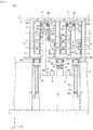
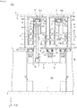
- Fig. 1 is a diagram showing an example of a storage system SYS according to a first embodiment, as viewed from the Y direction.
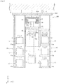
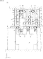
- Fig. 2 is a diagram showing the storage system SYS as viewed from the X direction.
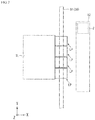
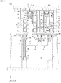
- Fig. 3 is a diagram schematically showing the storage system SYS as viewed in a plan view.
- an overhead crane track 20 and storages 11 of an overhead stocker 100 are shown in white
- an overhead track 30 and receiving/delivering ports 12 of an overhead transport vehicle system 200 are shown with hatched lines
- load ports LP of a processing apparatuses TL are shown in black.
- the storage system SYS shown in Fig. 1 to Fig. 3 is installed in a semiconductor device manufacturing factory or the like, and stores articles 2 such as FOUPs accommodating semiconductor wafers or reticle pods accommodating processing members such as reticles, which are used for manufacturing semiconductor devices.
- articles 2 such as FOUPs accommodating semiconductor wafers or reticle pods accommodating processing members such as reticles, which are used for manufacturing semiconductor devices.
- the articles 2 are FOUPs, but the articles 2 may be other types of articles other than FOUPs.
- the storage system SYS can also be applied to facilities of other fields other than the semiconductor field, and the articles 2 may be another type of articles that can be stored in the storage system SYS.
- the storage system SYS includes an overhead stocker 100, an overhead transport vehicle system 200, and a transporter 300.
- the overhead stocker 100 includes shelving 10 having a plurality of storages 11, an overhead crane track 20, and a crane 40.
- the shelving 10 is arranged on the inner side and on the outer side of the overhead crane track 20, on which the crane 40 travels (see Fig. 3 ).
- the plurality of storages 11 provided in the shelving 10 are held by a frame 13 and are arranged in three tiers in the vertical direction (the Z direction). The number of tiers of the storages 11 can be set arbitrarily.
- the plurality of storages 11 are arranged in line along the traveling direction (the Y direction) of the crane 40, which will be described later.
- the storage 11 means a space for placing and storing an article 2 therein or a storage space. That is to say, the storage 11 is a storage space for an article 2 in which a surface for placing an article 2 thereon (for example, the upper surface of a shelf board 11a) and the space between this surface and the ceiling or the like thereof (for example, the lower surface of the shelf board 11a) are combined.
- the plurality of storages 11 each include the shelf board 11a, on which an article 2 is placed.
- placing an article 2 in the storages 11 means placing the article 2 on the shelf board 11a of the storage 11.
- the shelving 10 is provided in a state of being suspended from a system ceiling SC1 by means of the frame 13.
- the system ceiling SC1 is arranged being suspended from a ceiling C of the building by means of metal hangers 3.
- the frame 13 may be suspended directly from the ceiling C instead of being suspended from the system ceiling SC1.
- a lower end of the shelving 10 is set higher than the height of the processing apparatus TL from the floor surface F.
- the processing apparatus TL performs various processes such as a film formation process or an etching process on semiconductor wafers accommodated in a FOUP, which is an article 2, for example.
- the height of a lower end of the crane 40 described later is also set higher than the height of the processing apparatus TL. That is to say, the overhead stocker 100 is arranged above the processing apparatus TL.
- the lower end of the crane 40 is set to a height with which operators can walk on the floor surface F with no hindrance. As a result, a part of the space below the overhead stocker 100 can be used as an operator passage PS.
- the crane 40 places an article 2 in the storage 11 and takes an article 2 therefrom.
- the second overhead transport vehicle 60 described later also places an article 2 in the storage 11 and takes an article 2 therefrom.
- the storage 11 from or to which the second overhead transport vehicle 60 receives or delivers an article 2 is the storage 11 on the uppermost tier of the shelving 10.
- the vertical dimension of the storage 11 is a dimension required for a transferer 42 of the crane 40, which will be described later, to lift an article 2.
- the transferer 42 of the crane 40 employs, for example, a configuration of supporting and lifting an article 2 from the lower surface side, and does not require a large space above the article 2.
- the vertical dimension of the storage 11 can be set to a dimension that would add several centimeters to the vertical dimension of the article 2.
- the overhead crane track 20 is provided in a state of being suspended from the system ceiling SC1 by means of metal hangers 5.
- the overhead crane track 20 may be suspended directly from the ceiling C instead of being suspended from the system ceiling SC1.
- the overhead crane track 20 is an annular track that has linear parts 21 extending in the Y direction and turning parts 22.
- the overhead crane track 20 being an annular track enables the shelving 10 to be installed on both sides in the X direction with respect to the two linear parts 21 in a plan view.
- the overhead crane track 20 is higher from the floor surface F than the overhead track 30 of the overhead transport vehicle system 200.
- the crane 40 travels on the overhead crane track 20 to hold and move an article 2.
- the crane 40 transfers the article 2 between a storage 11 and another storage 11.
- the crane 40 circulates and travels on the overhead crane track 20.
- the number of cranes 40 arranged on a single overhead crane track 20 is not limited to one.
- two or more cranes 40 may be arranged on a single overhead crane track 20.
- the crane 40 is provided in a state of being suspended from the overhead crane track 20.
- Fig. 4 is a diagram showing an example of the crane 40.
- the crane 40 travels on the overhead crane track 20 installed on the ceiling side, and it is, therefore, not necessary to provide a track on the floor surface F side (the ground side).
- the crane 40 includes two crane travelers 41 (see Fig. 2 ) and a transferer 42.
- An upper support 47 is attached to the lower side of the crane traveler 41 via an attacher 46, and two crane travelers 41 are connected by the upper support 47.
- Each crane traveler 41 includes a traveling driver not shown in the drawings and a plurality of wheels 41a, and travels along the overhead crane track 20.
- the traveling driver may be, for example, an electric motor which is provided in the crane traveler 41 to drive the wheels 41a, or may be a linear motor which is provided using the overhead crane track 20.
- the transferer 42 and the article 2, which are heavy objects can be reliably supported by using two crane travelers 41.
- the crane 40 uses two crane travelers 41, however, it is not limited to this configuration, and one, or three or more crane travelers 41 may be used.
- the transferer 42 includes masts 43, an elevation platform 44, drivers 45, an extender/retractor 48, and a placement platform 49.
- Each mast 43 extends in the vertical direction while being suspended from the upper support 47 (the crane traveler 41), and one mast 43 is provided at front and at rear respectively in the traveling direction of the crane traveler 41 (see Fig. 2 ).
- Each mast 43 is formed in a hollow or solid rod shape, and the cross section thereof is formed in a circular shape, an elliptical shape, an oval shape, or a polygonal shape such as a quadrangular shape.
- fastening members such as bolts and nuts may be used or welding or the like may be used, for example.
- the total number of masts 43 is not limited to two, and may be one. As mentioned above, the height of the lower end of the mast 43 from the floor surface F is set higher than the height of the processing apparatus TL. For example, the lower end of the mast 43 is the lower end of the crane 40.
- the extender/retractor is composed of a plurality of arms capable of extending and retracting in a direction orthogonal to the traveling direction of the crane traveler 41.
- the placement platform 49 is provided at a distal end of the extender/retractor 48.
- the placement platform 49 is a triangular plate-shaped member on which an article 2 can be placed.
- the placement platform 49 is a holder that holds the article 2 by placing the article 2 thereon.
- On the upper surface of the placement platform 49 there is provided a pin that is to be inserted into a groove provided on the bottom surface of the article 2 to position the article 2.
- the shelf board 11a mentioned above is provided with a cutout (not shown in the drawings) through which the placement platform 49 can pass in the vertical direction.
- the transferer 42 When receiving an article 2 from the storage 11, the transferer 42 raises the elevation platform 44 in a state where the extender/retractor 48 is extended and the placement platform 49 is positioned below the article 2, to thereby pick up the article 2 with the placement platform 49.
- the transferer 42 positions the placement platform 49 with the article 2 placed thereon above the elevation platform 44, by retracting the extender/retractor 48 while the article 2 is placed on the placement platform 49. Delivering of the article 2 to the storage 11 by means of the transferer 42 is performed by performing the above operations in a reversed manner.
- the transferer 42 is not limited to the above configuration, and may be of another configuration such as one in which a part of an article 2 (for example, a flange 2a provided on the upper part of a FOUP serving as the article 2) is held and raised.
- the drivers 45 raise or lower the elevation platform 44 along the masts 43, using a hoist or the like for example.
- Each driver 45 includes a suspender 45a and a driving unit not shown in the drawings.
- the suspenders 45a are belts or wires, and the elevation platform 44 is suspended from the upper support 47 by the suspenders 45a.
- the driving unit not shown in the drawings is provided on the upper support 47 and feeds out or winds up the suspenders 45a. When the driving unit feeds out the suspenders, the elevation platform 44 is lowered by being guided by the masts 43. When the driving unit winds up the suspenders 45a, the elevation platform 44 is raised, being guided by the masts 43.
- the drivers 45 are controlled by a controller or the like not shown in the drawings to lower or raise the elevation platform 44 at a predetermined speed.
- the drivers 45 are controlled by the controller or the like to maintain the elevation platform 44 at a target height.
- the drivers 45 are provided on the upper support 47 (the crane traveler 41).
- the drivers 45 may be provided, for example, on the elevation platform 44 instead of being provided on the upper support 47.
- the elevation platform 44 may be raised or lowered by winding up or feeding out the belts or wires suspended from the upper support 47, by means of a hoist or the like mounted on the elevation platform 44, for example.
- the elevation platform 44 may be raised or lowered by mounting an electric motor or the like that drives a pinion gear, forming a rack that meshes with the pinion gear, on the masts 43, and driving the electric motor and so forth to rotate the pinion gear.
- the overhead transport vehicle system 200 includes the overhead transport vehicle 50 that travels along the overhead track 30, and that receives or delivers articles 2 from or to the load port LP of the processing apparatus TL, which is a predetermined transfer destination arranged below the overhead track 30.
- the overhead track 30 is provided in a state of being attached to the lower face side of the system ceiling SC2.
- the system ceiling SC2 is arranged in a state of being suspended from the ceiling C by means of metal hangers 4.
- the overhead track 30 may be suspended from a system ceiling SC1 or from the ceiling C instead of being suspended from the system ceiling SC2.
- the overhead track 30 is arranged between an inter-bay route (inter-bay track) R1 and an inter-bay route R2 in a plan view.
- the overhead track 30 is an intra-bay route provided in each bay (in each intra-bay), and the inter-bay route R1 or the like is provided to connect a plurality of overhead tracks 30 serving as intra-bay routes, to each other.
- the overhead track 30 is connected from the inter-bay route R1 via two branch tracks S1 used for entering or exiting, and is connected from the inter-bay route R2 via two branch tracks S2 used for entering or exiting.
- the overhead track 30 has linear parts 31, turning parts 32, and branching parts 33.
- the overhead transport vehicle 50 can travel to circulate in one direction (for example, in the clockwise direction in a plan view) along the linear parts 31 and the turning parts 32.
- the linear parts 31 are arranged, directly above the load ports LP, in the Y direction along the plurality of load ports LP.
- the two linear parts 31 are arranged so as to be parallel to the linear parts 21 of the overhead crane track 20 in a plan view.
- the turning part 32 is arranged at both the +Y side end and at the -Y side end and includes curved parts, connecting the two linear parts 31 to each other.
- the branching part 33 is arranged on the inner side in a plan view on the overhead track 30, which is a circular track, and connects the two linear parts 31 to each other (see Fig. 3 ).
- a buffer B in which an article 2 can be placed, is provided on the +X side and on the -X side of the branching part 33 (see Fig. 1 ).
- the branching part 33 and the buffer B need not be provided.
- the overhead track 30 is arranged below the lower end (the lower end of the overhead stocker 100) of the crane 40 (the mast 43).
- the lower end of the crane 40 is set at a height H1 from the floor surface F
- the upper end of the overhead track 30 is set at a height H2 from the floor surface F (see Fig. 2 ).
- the height H2 is set lower than the height H1, and as a result, the overhead track 30 is arranged below the lower end of the overhead stocker 100.
- the overhead transport vehicle 50 that travels on the overhead track 30 travels below the lower end of the overhead stocker 100. With this configuration, the overhead stocker 100 and the overhead transport vehicle 50 of the overhead transport vehicle system 200 do not overlap with each other in a side view.
- the overhead transport vehicle 50 enters the overhead track 30 from the inter-bay route R1 or R2 via the branch track S1 or S2, or exits the overhead track 30 to the inter-bay route R1 or R2 via the branch track S1 or S2.
- the overhead transport vehicle 50 travels along the overhead track 30, and transfers articles 2 between the load ports LP of the processing apparatus TL and the receiving/delivering ports 12, which will be described later, on the linear part 31.
- the linear part 31 of the overhead track 30 extends directly above the plurality of load ports LP facing each other across a predetermined clearance (the operator passage PS).
- the load ports LP are provided at four locations on one processing apparatus TL (see Fig. 3 ), however, the configuration is not limited to this example.
- load ports LP may be provided at one to three locations on one processing apparatus TL, or may be provided at five or more locations. Since the overhead track 30 is provided directly above the load ports LP, the article 2 can be received from or delivered to the load port LP simply by the overhead transport vehicle 50 on the overhead track 30 raising and lowering the article 2.
- the overhead transport vehicle 50 on the overhead track 30 can receive or deliver the article 2 from or to the receiving/delivering port 12 by laterally extending the gripper 53 to the receiving/delivering port 12 (by a lateral transfer operation).
- the overhead transport vehicle 50 has a traveler 51 and a main body 52.
- the main body 52 includes the gripper 53 that holds an article 2, a lift driver 54 that raises or lowers the article 2 being held, and a lateral extender 55 that laterally moves the lift driver 54 relative to the traveler 51.
- the traveler 51 includes a traveling driver not shown in the drawings and a plurality of wheels 51a, and travels along the overhead track 30.
- the traveling driver may be, for example, an electric motor that is provided in the traveler 51 to drive the wheels 51a, or may be a linear motor that is provided using the overhead track 30.
- the main body 52 is attached to the lower part of the traveler 51 via an attacher 52a.
- the main body 52 has a gripper 53 that holds an article 2, the lift driver 54 that suspends and raises or lowers the gripper 53, and a lateral extender 55 that moves the lift driver 54 to a lateral side of the track.
- the gripper 53 grips the flange 2a of an article 2 from above, to thereby suspend and hold the article 2.
- the gripper 53 is, for example, a chuck having claws 53a capable of moving forward and backward in the horizontal direction, and it inserts the claws 53a under the flange 2a of the article 2 and raises the gripper 53 to thereby suspend and hold the article 2.
- the gripper 53 is connected to suspenders 53b such as wires and belts. The gripper 53 ascends or descends while being suspended from the lift driver 54.
- the lift driver 54 is, for example, a hoist, and lowers the gripper 53 by feeding out the suspenders 53b and raises the gripper 53 by winding up the suspenders 53b.
- the lift driver 54 is controlled by a controller or the like not shown in the drawings to lower or raise the gripper 53 at a predetermined speed. Also, the lift driver 54 is controlled by the controller to maintain the gripper 53 at a target height.
- the lateral extender 55 has movable plates stacked in the vertical direction, for example.
- the movable plates are movable to a lateral side of the traveling direction of the traveler 51 (in a direction orthogonal to the traveling direction, or in a lateral direction).
- the lift driver 54 is attached to the movable plates.
- the main body 52 has a guide not shown in the drawings that guides the lateral extender 55, and a driving unit not shown in the drawings that drives the lateral extender 55.
- the lateral extender 55 moves the lift driver 54 and the gripper 53 between a projecting position and a storing position, by means of the driving force of a driving unit such as an electric motor.
- the projecting position is a position at which the gripper 53 is projected to the lateral side from the main body 52.
- the storing position is a position at which the gripper 53 is stored in the main body 52.
- the overhead transport vehicle 50 can receive or deliver an article 2 from or to the load port LP by the lift driver 54 raising or lowering the article 2.
- the overhead transport vehicle 50 can also receive or deliver an article 2 from or to the receiving/delivering port 12 that is present below the lift driver 54 having been moved by the lateral extender 55, by raising or lowering the article 2 by means of the lift driver 54 in the state where the lateral extender 55 has moved the lift driver 54 to above any one of the plurality of receiving/delivering ports 12.
- a transporter 300 vertically transports an article 2 between the overhead stocker 100 and the overhead transport vehicle system 200.
- the transporter 300 is a second overhead transport vehicle 60.
- the storage system SYS includes a receiving/delivering port 12 for receiving or delivering an article 2 between the overhead transport vehicle system 200 and the transporter 300 (the second overhead transport vehicle 60).
- the receiving/delivering port 12 is arranged at a plurality of locations below the linear part 21 of the overhead crane track 20 on which the second overhead transport vehicle 60 travels.
- the receiving/delivering ports are provided on a lateral side of and below the overhead track 30.
- the second overhead transport vehicle 60 vertically transports articles 2 between the overhead stocker 100 and the receiving/delivering port 12.
- Fig. 5 is a diagram showing an example of the second overhead transport vehicle 60.
- the second overhead transport vehicle 60 has a second traveler 61 and a second main body 62.
- the second traveler 61 has a configuration similar to that of the crane traveler 41 of the crane applied thereto, and it includes a traveling driver not shown in the drawings and a plurality of wheels 61a, and travels along the overhead crane track 20.
- the second main body 62 is attached to the lower part of the second traveler 61 via an attacher 62a.
- the second main body 62 has a second gripper 63 that holds an article 2, a second lift driver 64 that raises or lowers the second gripper 63, and a second lateral extender 65 that moves the second lift driver 64 to a lateral side of the track.
- the second gripper 63 is, for example, a chuck having claws 63a and is connected to suspenders 63b.
- the second lift driver 64 is, for example, a hoist, and raises or lowers the second gripper 63 by feeding out or winding up the suspenders 63b.
- the second lateral extender 65 moves the second lift driver 64 and the second gripper 63 between a projecting position and a storing position.
- the projecting position is a position at which the second gripper 63 projects to the lateral side from the second main body 62.
- the storing position is a position at which the second gripper 63 is stored in the second main body 62.
- a rotating mechanism to rotate the second lift driver 64 (the second gripper 63) about an axis along the vertical direction.
- the second traveler 61, the second main body 62, the second gripper 63, the second lift driver 64, and the second lateral extender 65 have configurations similar to those of the traveler 51, the main body 52, and the gripper 53, the lift driver 54, and the lateral extender 55 of the above overhead transport vehicle 50 applied thereto. Therefore, the overhead transport vehicle 50 of the overhead transport vehicle system 200 can be applied to the second overhead transport vehicle 60 in an unchanged manner. Since the second overhead transport vehicle 60 travels on the overhead crane track 20, it is not necessary to provide a separate track, and the manufacturing cost of the storage system SYS can be reduced.
- the second overhead transport vehicle 60 can receive or deliver an article 2 from or to the receiving/delivering port 12 by the second lift driver 64 raising or lowering the article 2. Also, the second overhead transport vehicle 60 can receive or deliver an article 2 from or to the storage 11 that is present below the second lift driver 64 having been moved by the second lateral extender 65, by raising or lowering the article 2 by means of the second lift driver 64 in the state where the second lateral extender 65 has moved the second lift driver 64 to above at least one of the plurality of tiers of the storages 11. In the present embodiment, an article 2 can be received from or delivered to the uppermost tier storage 11 of the shelving 10. The storage 11 from or to which the second overhead transport vehicle 60 receives or delivers the article 2 may be a storage 11 other than the one on the uppermost tier.
- Fig. 6 is a diagram showing an enlarged view of a part of Fig. 3 , and shows an example of the positional relationship between the shelving 10 of the overhead stocker 100 and the load ports LP.
- a part of the shelving 10 overlaps with the load ports LP of the processing apparatus TL serving as a predetermined transfer destination as viewed in a plan view. Therefore, the shelving 10 can be expanded in the horizontal direction to above the load ports LP to store a large number of articles 2.
- the shelving 10 also overlaps with the overhead track 30 of the overhead transport vehicle system 200 in a plan view. That is to say, the shelving 10 can be provided regardless of the arrangement of the overhead track 30 of the overhead transport vehicle system 200. As a result, a high degree of freedom can be achieved in the arrangement of the shelving 10, and it is possible to easily realize an arrangement of the shelving 10 to accommodate articles 2 in a highly efficient manner.
- Fig. 7 is a diagram showing an enlarged view of a part of Fig. 3 , and shows an example of the positional relationship between the receiving/delivering port 12 and the load ports LP.
- the configuration on the overhead stocker 100 side is omitted.
- the receiving/delivering port 12 and the load ports LP are arranged so as not to overlap with each other in a plan view. That is to say, the receiving/delivering port 12 and the overhead track 30 of the overhead transport vehicle system 200 directly above the load ports LP are arranged so as to be apart from each other in a plan view (so as not to overlap with each other in the plan view).
- the second overhead transport vehicle 60 when the second overhead transport vehicle 60 receives or delivers an article 2 from or to the receiving/delivering port 12, it is possible to avoid interference with the overhead track 30 or with the overhead transport vehicle 50 traveling on the overhead track 30. Also, when the second overhead transport vehicle 60 receives or delivers an article 2 from or to the receiving/delivering port 12, the overhead transport vehicle 50 is still allowed to travel, and it is therefore possible to avoid reduction in the efficiency of the overhead transport vehicle system 200 transporting articles 2.
- the storage system SYS has a controller not shown in the drawings. This controller controls the storage system SYS in a comprehensive manner.
- the controller controls operations of the crane 40, the overhead transport vehicle 50, and the second overhead transport vehicle 60 by means of wireless or wired communication.
- the controller may be divided into a controller that controls the crane 40, a controller that controls the overhead transport vehicle 50, and a controller that controls the second overhead transport vehicle 60.
- Fig. 8 to Fig. 11 are diagrams showing an example of operations performed when an article 2 is transported from the storage unit 11 to the load port LP in the storage system SYS.
- the controller not shown in the drawings controls the second overhead transport vehicle 60 (the transporter 300) to receive the transport target article 2 from the uppermost tier storage 11 and then to deliver the article 2 to the specified receiving/delivering port 12.
- the crane 40 of the overhead stocker 100 transfers the article 2 to the uppermost tier storage 11 in the shelving 10.
- the second overhead transport vehicle 60 lowers the second gripper 63 by means of the second lift driver 64, and grips the article 2 by means of the second gripper 63.
- the second overhead transport vehicle 60 retracts the second lateral extender 65 and returns the second gripper 63 to the storing position, to thereby accommodate the article 2 in the second main body 62.
- the second overhead transport vehicle 60 travels along the overhead crane track 20 while holding the article 2 by means of the second gripper 63, and stops directly above the specified receiving/delivering port 12.
- the second overhead transport vehicle 60 releases the gripping of the second gripper 63 to thereby deliver the article 2 to the receiving/delivering port 12.
- the controller not shown in the drawings controls the overhead transport vehicle 50 of the overhead transport vehicle system 200 to receive the article 2 from the receiving/delivering port 12 and then to deliver the article 2 to the specified load port LP.
- the overhead transport vehicle 50 lowers the gripper 53 by means of the lift driver 54, and grips the article 2 by means of the gripper 53.
- the overhead transport vehicle 50 retracts the lateral extender 55 and returns the gripper 53 to the storing position, to thereby accommodate the article 2 in the main body 52.
- the overhead transport vehicle 50 travels along the overhead track 30 while holding the article 2 by means of the gripper 53, and stops directly above the specified load port LP.
- the overhead transport vehicle 50 releases the gripping of the gripper 53 to thereby deliver the article 2 to the load port LP.
- the article 2 is transported from the storage 11 (the shelving 10) of the overhead stocker 100 to the load port LP of the processing apparatus TL via the receiving/delivering port 12.
- the second overhead transport vehicle 60 of the overhead transport vehicle system 200 travels below the lower end of the overhead stocker 100. Therefore, even if the overhead track 30 of the overhead transport vehicle system 200 is installed to align with the load ports LP, the shelving 10 can be arranged regardless of the arrangement of the overhead track 30, and the efficiency of storing articles 2 can be improved. Moreover, storage of a large number of articles 2 becomes possible by expanding the shelving 10 easily in a horizontal direction. Since the crane 40 transfers articles 2 between the multiple tiers of storages 11, the articles 2 can easily be transferred even when the shelving 10 is expanded in the horizontal direction. Also, the second overhead transport vehicle 60 (the transporter 300) can efficiently transport articles 2 between the overhead stocker 100 and the overhead transport vehicle system 200, whereby the efficiency of transporting articles 2 can be improved.
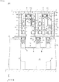
- Fig. 12 is a side view showing an example of a storage system SYS2 according to a second embodiment.
- Fig. 12 is a diagram showing the storage system SYS2 as viewed from the X direction.
- the same or similar configurations as or to those in the first embodiment described above are assigned with the same reference signs and the descriptions thereof are omitted or simplified.
- a conveyor 70 is used as a transporter 300A.
- the conveyor 70 has an upper port 14 arranged in a part of the lowermost tier of the plurality of storages 11, and a lower port 15 for receiving or delivering an article 2 from or to the overhead transport vehicle system 200. Therefore, the lower port 15 is a receiving/delivering port 12 for receiving or delivering an article 2 between the conveyor 70 (the transporter 300A) and the overhead transport vehicle system 200.
- An elevation shelf board 11b that can be raised and lowered in the vertical direction is arranged in the upper port 14 and the lower port 15. The elevation shelf board 11b is provided so as to allow an article 2 to be placed thereon, and can be raised or lowered between a first position P1 set in the upper port 14 and a second position P2 set in the lower port 15.
- both of the two conveyors 70 may transport articles 2 to or from the overhead stocker 100, or one of the conveyors 70 may be used to transport articles 2 from the overhead stocker 100 and the other conveyor 70 may be used to transport articles 2 into the overhead stocker 100.
- the number of conveyors 70 is arbitrary, and a single conveyor 70 may be used as the transporter 300A, or three or more conveyors 70 may be used.
- the controller when transporting an article 2 from the storage system 11 to the load port LP, controls the crane 40 so that the crane 40 of the overhead stocker 100 moves the article 2 from the storage 11 to the upper port 14. After having received the article 2 from the predetermined storage 11, the crane 40 travels along the overhead crane track 20 and stops at the side of the upper port 14 to deliver the article 2 to the elevation shelf board 11b in the upper port 14 by means of the transferer 42. The article 2 is transported from the storage 11 to the upper port 14 through this operation.
- the controller not shown in the drawings controls the conveyor 70 so that the conveyor 70 transports the article 2 from the upper port 14 to the lower port 15.
- the conveyor 70 lowers the elevation shelf board 11b with the article 2 placed thereon from the first position P1 to the second position P2.
- the article 2 moves to the lower port 15. That is to say, the article 2 is now placed on the receiving/delivering port 12.
- the controller not shown in the drawings controls the overhead transport vehicle 50 so that the overhead transport vehicle 50 of the overhead transport vehicle system 200 receives the article 2 from the elevation shelf board 11b of the lower port 15 and then delivers it to the load port LP.
- the overhead transport vehicle 50 After having traveled along the overhead track 30, stopped at a side of the elevation shelf board 11b of the lower port 15 in which the article 2 is placed, and caused the lateral extender 55 to project, the overhead transport vehicle 50 lowers the gripper 53 by means of the lift driver 54, and grips the article 2 by means of the gripper 53. Then, after having raised the gripper 53 by means of the lift driver 54, the overhead transport vehicle 50 retracts the lateral extender 55 and returns the gripper 53 to the storing position, to thereby accommodate the article 2 in the main body 52.
- the subsequent operation is similar to that of the above first embodiment in that the overhead transport vehicle 50 delivers the article 2 held by the gripper 53 to the specified load port LP.
- the article 2 is transported from the load port LP of the processing apparatus TL to the storage 11 of the overhead stocker 100 via the elevation shelf board 11b of the conveyor 70, by performing the above operations in the reversed manner.
- the transfer destination of the article 2 is other than the load port LP
- operations are similar to those described above
- operations are also similar to those described above.
- the shelving 10 can be arranged regardless of the arrangement of the overhead track 30, and the efficiency of storing articles 2 can be improved. Moreover, storage of a large number of articles 2 becomes possible by expanding the shelving 10 easily in a horizontal direction. Since the crane 40 transfers articles 2 between the multiple tiers of storages 11, the articles 2 can easily be transferred even when the shelving 10 is expanded in the horizontal direction. Also, the conveyor 70 (the transporter 300A) can efficiently transport articles 2 between the overhead stocker 100 and the overhead transport vehicle system 200, whereby the efficiency of transporting articles 2 can be improved.
- a local transport trolley may be used instead of the conveyor 70, which serves as the transporter 300A.
- This local transport trolley travels along a local track that is provided from directly above one or more storages 11 to directly above the receiving/delivering port 12, and includes a hoist that raises or lowers an article 2 while holding it. After having traveled along the local track, received an article 2 placed in the storage 11 directly below the local track, traveled along the local track, and stopped directly above the receiving/delivering port 12, the local transport trolley can deliver the article 2 to the receiving/delivering port 12 by means of the hoist lowering the article 2.
- the local transport trolley travels along the local track and stops directly above the storage 11. Then, the local transport trolley can deliver the article 2 to the storage 11 directly below the local transport trolley.
- articles 2 can be transported vertically between the overhead stocker 100 and the overhead transport vehicle system 200.
- the present invention is not limited to the above description, and various modifications may be made without departing from the gist of the invention.
- the configuration in which the overhead crane track 20 and the overhead track 30 are not connected in the storage systems SYS, SYS2 has been described as an example.
- the invention is not limited to this configuration.
- the overhead crane track 20 and the overhead track 30 may be connected via connection tracks or the like.
- the configuration in which the shelving 10, the overhead crane track 20, and the overhead track 30 are suspended from the ceiling C or from the system ceilings SC1, SC2 in the storage systems SYS, SYS2, has been described as an example.
- the invention is not limited to this configuration.
- at least one of the shelving 10, the overhead crane track 20, and the overhead track 30 may be supported by a supporting column, a frame, a pedestal, or the like provided on the floor surface F, so that the floor surface F bears the load of the shelving 10 and so forth.
Landscapes
- Engineering & Computer Science (AREA)
- Mechanical Engineering (AREA)
- Warehouses Or Storage Devices (AREA)
- Container, Conveyance, Adherence, Positioning, Of Wafer (AREA)
- Aerials With Secondary Devices (AREA)
Abstract
Description
- The present invention relates to a storage system.
- Overhead transport vehicles provided in an overhead traveling vehicle system are known to be used in semiconductor manufacturing factories to transport articles such as FOUPs for accommodating semiconductor wafers and reticle pods for accommodating reticles, and receive or deliver articles from or to transfer destinations such as a load port of a processing apparatus. Also, it has been proposed that articles be transported by means of overhead transport vehicles and placed in storages of shelving provided on the ceiling of a building or the like for storing (for example, see Patent Literature 1).
Patent Literature 1 discloses that articles are received or delivered from or to a storage of shelving, by means of an overhead transport vehicle that travels along an overhead track installed on a ceiling. - [Patent Literature 1]
Japanese Unexamined Patent Application, First Publication No. 2017-030944 - In
Patent Literature 1, shelving and an overhead transport vehicle are arranged so as to overlap with each other in a side view. The overhead track along which the overhead transport vehicle travels is arranged so as to travel, for example, directly above transfer destinations, corresponding to transfer destinations such as load ports. Therefore, as a result of installing the overhead track to align with the transfer destinations, there is a problem in that the shelving must be arranged in a space to avoid the overhead track, and consequently, expansion of the shelving in a horizontal direction becomes difficult. For example, there is a problem of inefficiency in storing articles in that, if the space between parallel overhead tracks is narrow, shelving cannot be provided therein, or an integer multiple number of shelvings cannot be arranged in line in certain spaces between parallel overhead tracks. - A purpose of the present invention is to provide a storage system capable of easily expanding shelving for storing articles, in a horizontal direction.
- A storage system according to an aspect of the present invention is a storage system comprising: an overhead stocker including an overhead crane track, shelving in which a plurality of tiers of storages for placing articles therein are arranged vertically, and a crane that travels along the overhead crane track and transfers an article between the plurality of tiers of storages; an overhead transport vehicle system that performs receiving or delivering of an article from or to a predetermined transfer destination; and a transporter that vertically transports an article between the overhead stocker and the overhead transport vehicle system, the overhead transport vehicle system being provided below a lower end of the overhead stocker.
- The storage system may comprise a receiving/delivering port for receiving or delivering an article between the overhead transport vehicle system and the transporter. A plurality of the receiving/delivering ports may be arranged.
- The overhead transport vehicle system may have an overhead track arranged below the lower end of the overhead stocker, and an overhead transport vehicle including a traveler that travels along the overhead track, a lift driver that raises or lowers an article being held, and a lateral extender that moves the lift driver laterally with respect to the traveler, the receiving/delivering port may be provided on a lateral side of and below the overhead track, and the overhead transport vehicle may be capable of receiving or delivering an article from or to the predetermined transfer destination by raising or lowering the article by means of the lift driver, and may be capable of receiving or delivering an article from or to the receiving/delivering port that is present below the lift driver having been moved by the lateral extender, by raising or lowering the article by means of the lift driver in the state where the lateral extender has moved the lift driver to above the receiving/delivering port.
- The transporter may be a second overhead transport vehicle including a second traveler that travels on the overhead crane track, a second lift driver that raises or lowers an article being held, and a second lateral extender that moves the second lift driver laterally with respect to the second traveler, the receiving/delivering port may be provided below the second overhead transport vehicle, and the second overhead transport vehicle may be capable of receiving or delivering an article from or to the receiving/delivering port by raising or lowering the article by means of the second lift driver, and may be capable of receiving or delivering an article from or to the storage that is present below the second lift driver having been moved by the second lateral extender, by raising or lowering the article by means of the second lift driver in the state where the second lateral extender has moved the second lift driver to above at least one of the plurality of tiers of the storages.
- The receiving/delivering port and the predetermined transfer destination may not be aligned as viewed in a plan view. A part of the shelving and the predetermined transfer destination may overlap with each other as viewed in a plan view. The crane may include a crane traveler that travels on the overhead crane track and a transferer that transfers an article between the plurality of tiers of the storages, and the transferer may include a mast that extends in a vertical direction while being suspended from the crane traveler, an elevation platform that ascends or descends along the mast, a driver that raises or lowers the elevation platform, an extender/retractor capable of extending from and retracting to the elevation platform, in a direction orthogonal to a traveling direction of the crane traveler, and a holder that is provided at a distal end of the extender/retractor and holds an article. Advantageous Effects of the Invention
- According to the storage system of the above aspect, the overhead stocker and the overhead transport vehicle system do not overlap with each other in a side view. Therefore, even when the overhead track of the overhead transport vehicle system is installed so as to align with a predetermined transfer destination, shelving can be arranged regardless of the arrangement of the overhead track, so that the shelving can easily be expanded in a horizontal direction, allowing a large number of articles to be stored efficiently. Since the crane transfers articles between the multiple tiers of storages, the articles can easily be transferred even when the shelving is expanded in a horizontal direction. The transporter can efficiently transport articles between the overhead stocker and the overhead transport vehicle system, whereby the efficiency of transporting articles can be improved.
- In a configuration provided with a receiving/delivering port to receive or deliver articles between the overhead transport vehicle system and the transporter, the overhead transport vehicle system or the transporter can start performing a subsequent operation as an article of the receiving/delivering target is placed on the receiving/delivering port, whereby receiving or delivering of articles can be performed efficiently. In a configuration in which a plurality of receiving/delivering ports are arranged, articles can be efficiently received or delivered between the overhead transport vehicle system and the transporter by placing the articles on the plurality of receiving/delivering ports.
- In a configuration such that the overhead transport vehicle system has an overhead track arranged below the lower end of the overhead stocker, and an overhead transport vehicle including a traveler that travels on the overhead track, a lift driver, and a lateral extender, the receiving/delivering port is provided on a lateral side of and below the overhead track, and the overhead transport vehicle is capable of receiving or delivering an article from or to the predetermined transfer destination by raising or lowering the article by means of the lift driver, and is capable of receiving or delivering an article from or to the receiving/delivering port that is present below the lift driver having been moved by the lateral extender, by raising or lowering the article by means of the lift driver in the state where the lateral extender has moved the lift driver to above the receiving/delivering port, articles can be received from or delivered to the predetermined transfer destination or the receiving/delivering port quickly and accurately by using the overhead transport vehicle in the overhead transport vehicle system.
- In a configuration such that the transporter is a second overhead transport vehicle including a second traveler that travels on the overhead crane track, a second lift driver, and a second lateral extender, the receiving/delivering port is provided below the second overhead transport vehicle, and the second overhead transport vehicle is capable of receiving or delivering an article from or to the receiving/delivering port by raising or lowering the article by means of the second lift driver, and is capable of receiving or delivering an article from or to the storage that is present below the second lift driver having been moved by the second lateral extender, by raising or lowering the article by means of the second lift driver in the state where the second lateral extender has moved the second lift driver to above at least one of the plurality of tiers of the storages, the second traveler of the second overhead transport vehicle travels on the overhead crane track, and it is therefore not necessary to separately provide a track for the traveler. By using such second overhead transport vehicle, articles can be received from or delivered to the predetermined transfer destination or the receiving/delivering port quickly and accurately.
- In a configuration such that the receiving/delivering port and the predetermined transfer destination are not aligned as viewed in a plan view, the overhead track of the overhead transport vehicle system can be arranged directly above the predetermined transfer destination, whereby an article can be received from or delivered to the predetermined transfer destination by the overhead transport vehicle raising or lowering the article. In a configuration such that a part of the shelving and the predetermined transfer destination overlap with each other as viewed in a plan view, the shelving can be expanded horizontally to above the predetermined transfer destination, and a large number of articles can be stored in the storage of the shelving. In a configuration such that the crane includes the crane traveler and the transferer mentioned above, and the transferer includes the mast, the elevation platform, the driver, the extender/retractor, and the holder mentioned above, articles can be transferred efficiently between the multiple tiers of storages.
-
-
Fig. 1 is a diagram showing an example of a storage system according to a first embodiment, as viewed from the Y direction. -
Fig. 2 is a diagram showing an example of the storage system shown inFig. 1 , as viewed from the Y direction. -
Fig. 3 is a diagram schematically showing the storage system in a plan view. -
Fig. 4 is a diagram showing an example of a crane of an overhead stocker. -
Fig. 5 is a diagram showing an example of a second overhead transport vehicle serving as a transporter. -
Fig. 6 is a diagram showing an enlarged view of a part ofFig 3 . -
Fig. 7 is a diagram showing an enlarged view of a part ofFig 3 . -
Fig. 8 is a diagram showing an operation of receiving an article from a storage, being performed by a transporter. -
Fig. 9 is a diagram showing an operation of delivering an article to a receiving/delivering port, being performed by the transporter. -
Fig. 10 is a diagram showing an operation of receiving an article from the receiving/delivering port, being performed by an overhead transport vehicle system. -
Fig. 11 is a diagram showing an operation of delivering an article to a predetermined transfer destination, being performed by the overhead transport vehicle system. -
Fig. 12 is a diagram showing an example of a storage system according to a second embodiment, as viewed from the X direction. - The following describes embodiments with reference to the drawings. However, the present invention is not limited to the embodiments. In the drawings, scale is changed as necessary to illustrate the embodiment, such as by enlarging or by emphasizing a part. In the following drawings, an XYZ coordinate system is used to describe the directions in each drawing. In this XYZ coordinate system, the vertical direction is taken as the Z direction, and the horizontal directions are taken as the X direction and the Y direction. The Y direction is one direction in the horizontal direction, and is the traveling direction of a
crane 40, anoverhead transport vehicle 50, and a secondoverhead transport vehicle 60, which will be described later. The X direction is a direction orthogonal to the Y direction. Also, in each of the X, Y, and Z directions, where appropriate, the orientation indicated by the arrow is expressed as a positive (+) direction (for example, +X direction), and the direction opposite thereof is expressed as a negative (-) direction (for example, -X direction). -
Fig. 1 is a diagram showing an example of a storage system SYS according to a first embodiment, as viewed from the Y direction.Fig. 2 is a diagram showing the storage system SYS as viewed from the X direction.Fig. 3 is a diagram schematically showing the storage system SYS as viewed in a plan view. InFig. 3 , in order to facilitate drawing distinctions in the figure, anoverhead crane track 20 andstorages 11 of anoverhead stocker 100 are shown in white, anoverhead track 30 and receiving/deliveringports 12 of an overheadtransport vehicle system 200 are shown with hatched lines, and load ports LP of a processing apparatuses TL are shown in black. - The storage system SYS shown in
Fig. 1 to Fig. 3 is installed in a semiconductor device manufacturing factory or the like, and storesarticles 2 such as FOUPs accommodating semiconductor wafers or reticle pods accommodating processing members such as reticles, which are used for manufacturing semiconductor devices. In the present embodiment, an example is described in which thearticles 2 are FOUPs, but thearticles 2 may be other types of articles other than FOUPs. The storage system SYS can also be applied to facilities of other fields other than the semiconductor field, and thearticles 2 may be another type of articles that can be stored in the storage system SYS. - As shown in
Fig. 1 to Fig. 3 , the storage system SYS includes anoverhead stocker 100, an overheadtransport vehicle system 200, and atransporter 300. Theoverhead stocker 100 includesshelving 10 having a plurality ofstorages 11, anoverhead crane track 20, and acrane 40. Theshelving 10 is arranged on the inner side and on the outer side of theoverhead crane track 20, on which thecrane 40 travels (seeFig. 3 ). As shown inFig. 1 , the plurality ofstorages 11 provided in theshelving 10 are held by aframe 13 and are arranged in three tiers in the vertical direction (the Z direction). The number of tiers of thestorages 11 can be set arbitrarily. The plurality ofstorages 11 are arranged in line along the traveling direction (the Y direction) of thecrane 40, which will be described later. In the present embodiment, thestorage 11 means a space for placing and storing anarticle 2 therein or a storage space. That is to say, thestorage 11 is a storage space for anarticle 2 in which a surface for placing anarticle 2 thereon (for example, the upper surface of ashelf board 11a) and the space between this surface and the ceiling or the like thereof (for example, the lower surface of theshelf board 11a) are combined. - The plurality of
storages 11 each include theshelf board 11a, on which anarticle 2 is placed. In the following description, placing anarticle 2 in thestorages 11 means placing thearticle 2 on theshelf board 11a of thestorage 11. On theshelf board 11a of thestorage 11, there may be provided a plurality of pins that enter grooves provided on the bottom surface of thearticle 2 when thearticle 2 is placed on theshelf board 11a. When these pins enter the grooves of thearticle 2, thearticle 2 is positioned with respect to thestorage 11. - The
shelving 10 is provided in a state of being suspended from a system ceiling SC1 by means of theframe 13. The system ceiling SC1 is arranged being suspended from a ceiling C of the building by means ofmetal hangers 3. Theframe 13 may be suspended directly from the ceiling C instead of being suspended from the system ceiling SC1. A lower end of theshelving 10 is set higher than the height of the processing apparatus TL from the floor surface F. The processing apparatus TL performs various processes such as a film formation process or an etching process on semiconductor wafers accommodated in a FOUP, which is anarticle 2, for example. The height of a lower end of thecrane 40 described later is also set higher than the height of the processing apparatus TL. That is to say, theoverhead stocker 100 is arranged above the processing apparatus TL. The lower end of thecrane 40 is set to a height with which operators can walk on the floor surface F with no hindrance. As a result, a part of the space below theoverhead stocker 100 can be used as an operator passage PS. - The
crane 40 places anarticle 2 in thestorage 11 and takes anarticle 2 therefrom. The secondoverhead transport vehicle 60 described later also places anarticle 2 in thestorage 11 and takes anarticle 2 therefrom. Thestorage 11 from or to which the secondoverhead transport vehicle 60 receives or delivers anarticle 2 is thestorage 11 on the uppermost tier of theshelving 10. The vertical dimension of thestorage 11 is a dimension required for atransferer 42 of thecrane 40, which will be described later, to lift anarticle 2. Thetransferer 42 of thecrane 40 employs, for example, a configuration of supporting and lifting anarticle 2 from the lower surface side, and does not require a large space above thearticle 2. For example, the vertical dimension of thestorage 11 can be set to a dimension that would add several centimeters to the vertical dimension of thearticle 2. - As shown in
Fig. 1 , theoverhead crane track 20 is provided in a state of being suspended from the system ceiling SC1 by means ofmetal hangers 5. Theoverhead crane track 20 may be suspended directly from the ceiling C instead of being suspended from the system ceiling SC1. As shown inFig. 3 , theoverhead crane track 20 is an annular track that haslinear parts 21 extending in the Y direction and turningparts 22. Theoverhead crane track 20 being an annular track enables theshelving 10 to be installed on both sides in the X direction with respect to the twolinear parts 21 in a plan view. As shown inFig. 1 , theoverhead crane track 20 is higher from the floor surface F than theoverhead track 30 of the overheadtransport vehicle system 200. - The
crane 40 travels on theoverhead crane track 20 to hold and move anarticle 2. Thecrane 40 transfers thearticle 2 between astorage 11 and anotherstorage 11. Thecrane 40 circulates and travels on theoverhead crane track 20. The number ofcranes 40 arranged on a singleoverhead crane track 20 is not limited to one. For example, two ormore cranes 40 may be arranged on a singleoverhead crane track 20. As shown inFig. 1 andFig. 2 , thecrane 40 is provided in a state of being suspended from theoverhead crane track 20. -
Fig. 4 is a diagram showing an example of thecrane 40. Thecrane 40 travels on theoverhead crane track 20 installed on the ceiling side, and it is, therefore, not necessary to provide a track on the floor surface F side (the ground side). Thecrane 40 includes two crane travelers 41 (seeFig. 2 ) and atransferer 42. Anupper support 47 is attached to the lower side of thecrane traveler 41 via anattacher 46, and twocrane travelers 41 are connected by theupper support 47. Eachcrane traveler 41 includes a traveling driver not shown in the drawings and a plurality ofwheels 41a, and travels along theoverhead crane track 20. The traveling driver may be, for example, an electric motor which is provided in thecrane traveler 41 to drive thewheels 41a, or may be a linear motor which is provided using theoverhead crane track 20. - In the
crane 40 of the present embodiment, thetransferer 42 and thearticle 2, which are heavy objects, can be reliably supported by using twocrane travelers 41. Thecrane 40 uses twocrane travelers 41, however, it is not limited to this configuration, and one, or three ormore crane travelers 41 may be used. - The
transferer 42 includesmasts 43, anelevation platform 44,drivers 45, an extender/retractor 48, and aplacement platform 49. Eachmast 43 extends in the vertical direction while being suspended from the upper support 47 (the crane traveler 41), and onemast 43 is provided at front and at rear respectively in the traveling direction of the crane traveler 41 (seeFig. 2 ). Eachmast 43 is formed in a hollow or solid rod shape, and the cross section thereof is formed in a circular shape, an elliptical shape, an oval shape, or a polygonal shape such as a quadrangular shape. For attachment of themasts 43 to theupper support 47, fastening members such as bolts and nuts may be used or welding or the like may be used, for example. The total number ofmasts 43 is not limited to two, and may be one. As mentioned above, the height of the lower end of themast 43 from the floor surface F is set higher than the height of the processing apparatus TL. For example, the lower end of themast 43 is the lower end of thecrane 40. - The extender/retractor is composed of a plurality of arms capable of extending and retracting in a direction orthogonal to the traveling direction of the
crane traveler 41. Theplacement platform 49 is provided at a distal end of the extender/retractor 48. Theplacement platform 49 is a triangular plate-shaped member on which anarticle 2 can be placed. Theplacement platform 49 is a holder that holds thearticle 2 by placing thearticle 2 thereon. On the upper surface of theplacement platform 49, there is provided a pin that is to be inserted into a groove provided on the bottom surface of thearticle 2 to position thearticle 2. Theshelf board 11a mentioned above is provided with a cutout (not shown in the drawings) through which theplacement platform 49 can pass in the vertical direction. - When receiving an
article 2 from thestorage 11, thetransferer 42 raises theelevation platform 44 in a state where the extender/retractor 48 is extended and theplacement platform 49 is positioned below thearticle 2, to thereby pick up thearticle 2 with theplacement platform 49. Thetransferer 42 positions theplacement platform 49 with thearticle 2 placed thereon above theelevation platform 44, by retracting the extender/retractor 48 while thearticle 2 is placed on theplacement platform 49. Delivering of thearticle 2 to thestorage 11 by means of thetransferer 42 is performed by performing the above operations in a reversed manner. Thetransferer 42 is not limited to the above configuration, and may be of another configuration such as one in which a part of an article 2 (for example, aflange 2a provided on the upper part of a FOUP serving as the article 2) is held and raised. - The
drivers 45 raise or lower theelevation platform 44 along themasts 43, using a hoist or the like for example. Eachdriver 45 includes asuspender 45a and a driving unit not shown in the drawings. Thesuspenders 45a are belts or wires, and theelevation platform 44 is suspended from theupper support 47 by thesuspenders 45a. The driving unit not shown in the drawings is provided on theupper support 47 and feeds out or winds up thesuspenders 45a. When the driving unit feeds out the suspenders, theelevation platform 44 is lowered by being guided by themasts 43. When the driving unit winds up thesuspenders 45a, theelevation platform 44 is raised, being guided by themasts 43. Thedrivers 45 are controlled by a controller or the like not shown in the drawings to lower or raise theelevation platform 44 at a predetermined speed. Thedrivers 45 are controlled by the controller or the like to maintain theelevation platform 44 at a target height. - As shown in
Fig. 4 , thedrivers 45 are provided on the upper support 47 (the crane traveler 41). Thedrivers 45 may be provided, for example, on theelevation platform 44 instead of being provided on theupper support 47. As a configuration of providing thedrivers 45 on theelevation platform 44, theelevation platform 44 may be raised or lowered by winding up or feeding out the belts or wires suspended from theupper support 47, by means of a hoist or the like mounted on theelevation platform 44, for example. Also, theelevation platform 44 may be raised or lowered by mounting an electric motor or the like that drives a pinion gear, forming a rack that meshes with the pinion gear, on themasts 43, and driving the electric motor and so forth to rotate the pinion gear. - The overhead
transport vehicle system 200 includes theoverhead transport vehicle 50 that travels along theoverhead track 30, and that receives or deliversarticles 2 from or to the load port LP of the processing apparatus TL, which is a predetermined transfer destination arranged below theoverhead track 30. As shown inFig. 1 , theoverhead track 30 is provided in a state of being attached to the lower face side of the system ceiling SC2. The system ceiling SC2 is arranged in a state of being suspended from the ceiling C by means ofmetal hangers 4. Theoverhead track 30 may be suspended from a system ceiling SC1 or from the ceiling C instead of being suspended from the system ceiling SC2. - The
overhead track 30 is arranged between an inter-bay route (inter-bay track) R1 and an inter-bay route R2 in a plan view. Theoverhead track 30 is an intra-bay route provided in each bay (in each intra-bay), and the inter-bay route R1 or the like is provided to connect a plurality ofoverhead tracks 30 serving as intra-bay routes, to each other. Theoverhead track 30 is connected from the inter-bay route R1 via two branch tracks S1 used for entering or exiting, and is connected from the inter-bay route R2 via two branch tracks S2 used for entering or exiting. - The
overhead track 30 haslinear parts 31, turningparts 32, and branchingparts 33. Theoverhead transport vehicle 50 can travel to circulate in one direction (for example, in the clockwise direction in a plan view) along thelinear parts 31 and the turningparts 32. Thelinear parts 31 are arranged, directly above the load ports LP, in the Y direction along the plurality of load ports LP. The twolinear parts 31 are arranged so as to be parallel to thelinear parts 21 of theoverhead crane track 20 in a plan view. The turningpart 32 is arranged at both the +Y side end and at the -Y side end and includes curved parts, connecting the twolinear parts 31 to each other. The branchingpart 33 is arranged on the inner side in a plan view on theoverhead track 30, which is a circular track, and connects the twolinear parts 31 to each other (seeFig. 3 ). A buffer B, in which anarticle 2 can be placed, is provided on the +X side and on the -X side of the branching part 33 (seeFig. 1 ). The branchingpart 33 and the buffer B need not be provided. - The
overhead track 30 is arranged below the lower end (the lower end of the overhead stocker 100) of the crane 40 (the mast 43). The lower end of thecrane 40 is set at a height H1 from the floor surface F, and the upper end of theoverhead track 30 is set at a height H2 from the floor surface F (seeFig. 2 ). The height H2 is set lower than the height H1, and as a result, theoverhead track 30 is arranged below the lower end of theoverhead stocker 100. Theoverhead transport vehicle 50 that travels on theoverhead track 30 travels below the lower end of theoverhead stocker 100. With this configuration, theoverhead stocker 100 and theoverhead transport vehicle 50 of the overheadtransport vehicle system 200 do not overlap with each other in a side view. - The
overhead transport vehicle 50 enters theoverhead track 30 from the inter-bay route R1 or R2 via the branch track S1 or S2, or exits theoverhead track 30 to the inter-bay route R1 or R2 via the branch track S1 or S2. Theoverhead transport vehicle 50 travels along theoverhead track 30, and transfersarticles 2 between the load ports LP of the processing apparatus TL and the receiving/deliveringports 12, which will be described later, on thelinear part 31. - The
linear part 31 of theoverhead track 30 extends directly above the plurality of load ports LP facing each other across a predetermined clearance (the operator passage PS). In the present embodiment, the load ports LP are provided at four locations on one processing apparatus TL (seeFig. 3 ), however, the configuration is not limited to this example. For example, load ports LP may be provided at one to three locations on one processing apparatus TL, or may be provided at five or more locations. Since theoverhead track 30 is provided directly above the load ports LP, thearticle 2 can be received from or delivered to the load port LP simply by theoverhead transport vehicle 50 on theoverhead track 30 raising and lowering thearticle 2. Theoverhead transport vehicle 50 on theoverhead track 30 can receive or deliver thearticle 2 from or to the receiving/deliveringport 12 by laterally extending thegripper 53 to the receiving/delivering port 12 (by a lateral transfer operation). - As shown in
Fig. 1 andFig. 2 , theoverhead transport vehicle 50 has atraveler 51 and amain body 52. Themain body 52 includes thegripper 53 that holds anarticle 2, alift driver 54 that raises or lowers thearticle 2 being held, and alateral extender 55 that laterally moves thelift driver 54 relative to thetraveler 51. Thetraveler 51 includes a traveling driver not shown in the drawings and a plurality of wheels 51a, and travels along theoverhead track 30. The traveling driver may be, for example, an electric motor that is provided in thetraveler 51 to drive the wheels 51a, or may be a linear motor that is provided using theoverhead track 30. - The
main body 52 is attached to the lower part of thetraveler 51 via an attacher 52a. Themain body 52 has agripper 53 that holds anarticle 2, thelift driver 54 that suspends and raises or lowers thegripper 53, and alateral extender 55 that moves thelift driver 54 to a lateral side of the track. Thegripper 53 grips theflange 2a of anarticle 2 from above, to thereby suspend and hold thearticle 2. Thegripper 53 is, for example, achuck having claws 53a capable of moving forward and backward in the horizontal direction, and it inserts theclaws 53a under theflange 2a of thearticle 2 and raises thegripper 53 to thereby suspend and hold thearticle 2. Thegripper 53 is connected tosuspenders 53b such as wires and belts. Thegripper 53 ascends or descends while being suspended from thelift driver 54. - The
lift driver 54 is, for example, a hoist, and lowers thegripper 53 by feeding out thesuspenders 53b and raises thegripper 53 by winding up thesuspenders 53b. Thelift driver 54 is controlled by a controller or the like not shown in the drawings to lower or raise thegripper 53 at a predetermined speed. Also, thelift driver 54 is controlled by the controller to maintain thegripper 53 at a target height. - The
lateral extender 55 has movable plates stacked in the vertical direction, for example. The movable plates are movable to a lateral side of the traveling direction of the traveler 51 (in a direction orthogonal to the traveling direction, or in a lateral direction). Thelift driver 54 is attached to the movable plates. Themain body 52 has a guide not shown in the drawings that guides thelateral extender 55, and a driving unit not shown in the drawings that drives thelateral extender 55. Thelateral extender 55 moves thelift driver 54 and thegripper 53 between a projecting position and a storing position, by means of the driving force of a driving unit such as an electric motor. The projecting position is a position at which thegripper 53 is projected to the lateral side from themain body 52. The storing position is a position at which thegripper 53 is stored in themain body 52. A rotating mechanism to rotate the lift driver 54 (the gripper 53) about an axis along the vertical direction between thelift driver 54 and thegripper 53. - The
overhead transport vehicle 50 can receive or deliver anarticle 2 from or to the load port LP by thelift driver 54 raising or lowering thearticle 2. Theoverhead transport vehicle 50 can also receive or deliver anarticle 2 from or to the receiving/deliveringport 12 that is present below thelift driver 54 having been moved by thelateral extender 55, by raising or lowering thearticle 2 by means of thelift driver 54 in the state where thelateral extender 55 has moved thelift driver 54 to above any one of the plurality of receiving/deliveringports 12. - A
transporter 300 vertically transports anarticle 2 between theoverhead stocker 100 and the overheadtransport vehicle system 200. In the present embodiment, thetransporter 300 is a secondoverhead transport vehicle 60. The storage system SYS includes a receiving/deliveringport 12 for receiving or delivering anarticle 2 between the overheadtransport vehicle system 200 and the transporter 300 (the second overhead transport vehicle 60). The receiving/deliveringport 12 is arranged at a plurality of locations below thelinear part 21 of theoverhead crane track 20 on which the secondoverhead transport vehicle 60 travels. The receiving/delivering ports are provided on a lateral side of and below theoverhead track 30. As a result, as described above, theoverhead transport vehicle 50 can receive or deliver anarticle 2 from or to the receiving/deliveringport 12 through a lateral transfer operation). - The second
overhead transport vehicle 60 vertically transportsarticles 2 between theoverhead stocker 100 and the receiving/deliveringport 12.Fig. 5 is a diagram showing an example of the secondoverhead transport vehicle 60. The secondoverhead transport vehicle 60 has asecond traveler 61 and a secondmain body 62. Thesecond traveler 61 has a configuration similar to that of thecrane traveler 41 of the crane applied thereto, and it includes a traveling driver not shown in the drawings and a plurality ofwheels 61a, and travels along theoverhead crane track 20. - The second
main body 62 is attached to the lower part of thesecond traveler 61 via anattacher 62a. The secondmain body 62 has asecond gripper 63 that holds anarticle 2, asecond lift driver 64 that raises or lowers thesecond gripper 63, and a secondlateral extender 65 that moves thesecond lift driver 64 to a lateral side of the track. Thesecond gripper 63 is, for example, achuck having claws 63a and is connected tosuspenders 63b. - The
second lift driver 64 is, for example, a hoist, and raises or lowers thesecond gripper 63 by feeding out or winding up thesuspenders 63b. The secondlateral extender 65 moves thesecond lift driver 64 and thesecond gripper 63 between a projecting position and a storing position. The projecting position is a position at which thesecond gripper 63 projects to the lateral side from the secondmain body 62. The storing position is a position at which thesecond gripper 63 is stored in the secondmain body 62. Between the secondlateral extender 65 and thesecond lift driver 64, there may be provided a rotating mechanism to rotate the second lift driver 64 (the second gripper 63) about an axis along the vertical direction. - The
second traveler 61, the secondmain body 62, thesecond gripper 63, thesecond lift driver 64, and the secondlateral extender 65 have configurations similar to those of thetraveler 51, themain body 52, and thegripper 53, thelift driver 54, and thelateral extender 55 of the aboveoverhead transport vehicle 50 applied thereto. Therefore, theoverhead transport vehicle 50 of the overheadtransport vehicle system 200 can be applied to the secondoverhead transport vehicle 60 in an unchanged manner. Since the secondoverhead transport vehicle 60 travels on theoverhead crane track 20, it is not necessary to provide a separate track, and the manufacturing cost of the storage system SYS can be reduced. - The second
overhead transport vehicle 60 can receive or deliver anarticle 2 from or to the receiving/deliveringport 12 by thesecond lift driver 64 raising or lowering thearticle 2. Also, the secondoverhead transport vehicle 60 can receive or deliver anarticle 2 from or to thestorage 11 that is present below thesecond lift driver 64 having been moved by the secondlateral extender 65, by raising or lowering thearticle 2 by means of thesecond lift driver 64 in the state where the secondlateral extender 65 has moved thesecond lift driver 64 to above at least one of the plurality of tiers of thestorages 11. In the present embodiment, anarticle 2 can be received from or delivered to theuppermost tier storage 11 of theshelving 10. Thestorage 11 from or to which the secondoverhead transport vehicle 60 receives or delivers thearticle 2 may be astorage 11 other than the one on the uppermost tier. -
Fig. 6 is a diagram showing an enlarged view of a part ofFig. 3 , and shows an example of the positional relationship between the shelving 10 of theoverhead stocker 100 and the load ports LP. As shown inFig. 6 , in the present embodiment, a part of theshelving 10 overlaps with the load ports LP of the processing apparatus TL serving as a predetermined transfer destination as viewed in a plan view. Therefore, theshelving 10 can be expanded in the horizontal direction to above the load ports LP to store a large number ofarticles 2. Theshelving 10 also overlaps with theoverhead track 30 of the overheadtransport vehicle system 200 in a plan view. That is to say, theshelving 10 can be provided regardless of the arrangement of theoverhead track 30 of the overheadtransport vehicle system 200. As a result, a high degree of freedom can be achieved in the arrangement of theshelving 10, and it is possible to easily realize an arrangement of theshelving 10 to accommodatearticles 2 in a highly efficient manner. -
Fig. 7 is a diagram showing an enlarged view of a part ofFig. 3 , and shows an example of the positional relationship between the receiving/deliveringport 12 and the load ports LP. InFig. 7 , in order to facilitate drawing distinctions in the figure, the configuration on theoverhead stocker 100 side is omitted. As shown inFig. 7 , the receiving/deliveringport 12 and the load ports LP are arranged so as not to overlap with each other in a plan view. That is to say, the receiving/deliveringport 12 and theoverhead track 30 of the overheadtransport vehicle system 200 directly above the load ports LP are arranged so as to be apart from each other in a plan view (so as not to overlap with each other in the plan view). - As a result, when the second
overhead transport vehicle 60 receives or delivers anarticle 2 from or to the receiving/deliveringport 12, it is possible to avoid interference with theoverhead track 30 or with theoverhead transport vehicle 50 traveling on theoverhead track 30. Also, when the secondoverhead transport vehicle 60 receives or delivers anarticle 2 from or to the receiving/deliveringport 12, theoverhead transport vehicle 50 is still allowed to travel, and it is therefore possible to avoid reduction in the efficiency of the overheadtransport vehicle system 200 transportingarticles 2. - The storage system SYS has a controller not shown in the drawings. This controller controls the storage system SYS in a comprehensive manner. The controller controls operations of the
crane 40, theoverhead transport vehicle 50, and the secondoverhead transport vehicle 60 by means of wireless or wired communication. The controller may be divided into a controller that controls thecrane 40, a controller that controls theoverhead transport vehicle 50, and a controller that controls the secondoverhead transport vehicle 60. -
Fig. 8 to Fig. 11 are diagrams showing an example of operations performed when anarticle 2 is transported from thestorage unit 11 to the load port LP in the storage system SYS. The controller not shown in the drawings controls the second overhead transport vehicle 60 (the transporter 300) to receive thetransport target article 2 from theuppermost tier storage 11 and then to deliver thearticle 2 to the specified receiving/deliveringport 12. First, when thetransport target article 2 is in astorage 11 other than the one on the uppermost tier, thecrane 40 of theoverhead stocker 100 transfers thearticle 2 to theuppermost tier storage 11 in theshelving 10. - Next, as shown in
Fig. 8 , after having traveled along theoverhead crane track 20, stopped at a side of thestorage 11 in which thetransport target article 2 is placed, and caused thesecond lift driver 64 to project by means of the secondlateral extender 65, the secondoverhead transport vehicle 60 lowers thesecond gripper 63 by means of thesecond lift driver 64, and grips thearticle 2 by means of thesecond gripper 63. Next, after having raised thesecond gripper 63 by means of thesecond lift driver 64, the secondoverhead transport vehicle 60 retracts the secondlateral extender 65 and returns thesecond gripper 63 to the storing position, to thereby accommodate thearticle 2 in the secondmain body 62. - Next, the second
overhead transport vehicle 60 travels along theoverhead crane track 20 while holding thearticle 2 by means of thesecond gripper 63, and stops directly above the specified receiving/deliveringport 12. Next, as shown inFig. 9 , after having driven thesecond lift driver 64 to lower thesecond gripper 63 and thearticle 2 and placed thearticle 2 on the receiving/deliveringport 12, the secondoverhead transport vehicle 60 releases the gripping of thesecond gripper 63 to thereby deliver thearticle 2 to the receiving/deliveringport 12. - Next, the controller not shown in the drawings controls the
overhead transport vehicle 50 of the overheadtransport vehicle system 200 to receive thearticle 2 from the receiving/deliveringport 12 and then to deliver thearticle 2 to the specified load port LP. As shown inFig. 10 , after having traveled along theoverhead track 30, stopped at a side of the receiving/deliveringport 12 in which thearticle 2 is placed, and caused thelift driver 54 to project by means of thelateral extender 55, theoverhead transport vehicle 50 lowers thegripper 53 by means of thelift driver 54, and grips thearticle 2 by means of thegripper 53. Then, after having raised thegripper 53 by means of thelift driver 54, theoverhead transport vehicle 50 retracts thelateral extender 55 and returns thegripper 53 to the storing position, to thereby accommodate thearticle 2 in themain body 52. - Next, the
overhead transport vehicle 50 travels along theoverhead track 30 while holding thearticle 2 by means of thegripper 53, and stops directly above the specified load port LP. Next, as shown inFig. 11 , after having driven thelift driver 54 to lower thegripper 53 and thearticle 2 and placed thearticle 2 on the load port LP, theoverhead transport vehicle 50 releases the gripping of thegripper 53 to thereby deliver thearticle 2 to the load port LP. Through the series of these operations, thearticle 2 is transported from the storage 11 (the shelving 10) of theoverhead stocker 100 to the load port LP of the processing apparatus TL via the receiving/deliveringport 12. - When transporting an
article 2 from the load port LP of the processing apparatus TL to thestorage 11 of theoverhead stocker 100, the series of above operations shown inFig. 8 to Fig. 11 are performed in a reversed manner. Thereby, thearticle 2 is transported from the load port LP of the processing apparatus TL to thestorage 11 of theoverhead stocker 100 via the receiving/deliveringport 12. In a case where the transfer destination of thearticle 2 is other than the load port LP, operations are similar to those described above and operations are also similar to those described above in a case where thearticle 2 is received from a location other than the load port LP. - As described above, according to the storage system SYS of the present embodiment, the second
overhead transport vehicle 60 of the overheadtransport vehicle system 200 travels below the lower end of theoverhead stocker 100. Therefore, even if theoverhead track 30 of the overheadtransport vehicle system 200 is installed to align with the load ports LP, theshelving 10 can be arranged regardless of the arrangement of theoverhead track 30, and the efficiency of storingarticles 2 can be improved. Moreover, storage of a large number ofarticles 2 becomes possible by expanding theshelving 10 easily in a horizontal direction. Since thecrane 40transfers articles 2 between the multiple tiers ofstorages 11, thearticles 2 can easily be transferred even when theshelving 10 is expanded in the horizontal direction. Also, the second overhead transport vehicle 60 (the transporter 300) can efficiently transportarticles 2 between theoverhead stocker 100 and the overheadtransport vehicle system 200, whereby the efficiency of transportingarticles 2 can be improved. - The above first embodiment described a configuration in which the
transporter 300 is the secondoverhead transport vehicle 60, however, the invention is not limited to this configuration.Fig. 12 is a side view showing an example of a storage system SYS2 according to a second embodiment.Fig. 12 is a diagram showing the storage system SYS2 as viewed from the X direction. In the following description, the same or similar configurations as or to those in the first embodiment described above are assigned with the same reference signs and the descriptions thereof are omitted or simplified. - In the storage system SYS2 shown in
Fig. 12 , aconveyor 70 is used as atransporter 300A. Theconveyor 70 has anupper port 14 arranged in a part of the lowermost tier of the plurality ofstorages 11, and alower port 15 for receiving or delivering anarticle 2 from or to the overheadtransport vehicle system 200. Therefore, thelower port 15 is a receiving/deliveringport 12 for receiving or delivering anarticle 2 between the conveyor 70 (thetransporter 300A) and the overheadtransport vehicle system 200. Anelevation shelf board 11b that can be raised and lowered in the vertical direction is arranged in theupper port 14 and thelower port 15. Theelevation shelf board 11b is provided so as to allow anarticle 2 to be placed thereon, and can be raised or lowered between a first position P1 set in theupper port 14 and a second position P2 set in thelower port 15. - In
Fig. 12 , twoconveyors 70 are used. In such a case, both of the twoconveyors 70 may transportarticles 2 to or from theoverhead stocker 100, or one of theconveyors 70 may be used to transportarticles 2 from theoverhead stocker 100 and theother conveyor 70 may be used to transportarticles 2 into theoverhead stocker 100. The number ofconveyors 70 is arbitrary, and asingle conveyor 70 may be used as thetransporter 300A, or three ormore conveyors 70 may be used. - In the storage system SYS2, when transporting an
article 2 from thestorage system 11 to the load port LP, the controller not shown in the drawings controls thecrane 40 so that thecrane 40 of theoverhead stocker 100 moves thearticle 2 from thestorage 11 to theupper port 14. After having received thearticle 2 from thepredetermined storage 11, thecrane 40 travels along theoverhead crane track 20 and stops at the side of theupper port 14 to deliver thearticle 2 to theelevation shelf board 11b in theupper port 14 by means of thetransferer 42. Thearticle 2 is transported from thestorage 11 to theupper port 14 through this operation. - Subsequently, the controller not shown in the drawings controls the
conveyor 70 so that theconveyor 70 transports thearticle 2 from theupper port 14 to thelower port 15. Theconveyor 70 lowers theelevation shelf board 11b with thearticle 2 placed thereon from the first position P1 to the second position P2. As a result, thearticle 2 moves to thelower port 15. That is to say, thearticle 2 is now placed on the receiving/deliveringport 12. - Next, the controller not shown in the drawings controls the
overhead transport vehicle 50 so that theoverhead transport vehicle 50 of the overheadtransport vehicle system 200 receives thearticle 2 from theelevation shelf board 11b of thelower port 15 and then delivers it to the load port LP. After having traveled along theoverhead track 30, stopped at a side of theelevation shelf board 11b of thelower port 15 in which thearticle 2 is placed, and caused thelateral extender 55 to project, theoverhead transport vehicle 50 lowers thegripper 53 by means of thelift driver 54, and grips thearticle 2 by means of thegripper 53. Then, after having raised thegripper 53 by means of thelift driver 54, theoverhead transport vehicle 50 retracts thelateral extender 55 and returns thegripper 53 to the storing position, to thereby accommodate thearticle 2 in themain body 52. - The subsequent operation is similar to that of the above first embodiment in that the
overhead transport vehicle 50 delivers thearticle 2 held by thegripper 53 to the specified load port LP. When transporting thearticle 2 from the load port LP of the processing apparatus TL to thestorage 11 of theoverhead stocker 100, thearticle 2 is transported from the load port LP of the processing apparatus TL to thestorage 11 of theoverhead stocker 100 via theelevation shelf board 11b of theconveyor 70, by performing the above operations in the reversed manner. In a case where the transfer destination of thearticle 2 is other than the load port LP, operations are similar to those described above, and in a case where thearticle 2 is received from a location other than the load port LP, operations are also similar to those described above. - As described above, according to the storage system SYS2 of the second embodiment, as with the storage system SYS of the first embodiment, even if the
overhead track 30 of the overheadtransport vehicle system 200 is installed to align with the load ports LP, theshelving 10 can be arranged regardless of the arrangement of theoverhead track 30, and the efficiency of storingarticles 2 can be improved. Moreover, storage of a large number ofarticles 2 becomes possible by expanding theshelving 10 easily in a horizontal direction. Since thecrane 40transfers articles 2 between the multiple tiers ofstorages 11, thearticles 2 can easily be transferred even when theshelving 10 is expanded in the horizontal direction. Also, the conveyor 70 (thetransporter 300A) can efficiently transportarticles 2 between theoverhead stocker 100 and the overheadtransport vehicle system 200, whereby the efficiency of transportingarticles 2 can be improved. - In the storage system SYS2, for example, a local transport trolley may be used instead of the
conveyor 70, which serves as thetransporter 300A. This local transport trolley travels along a local track that is provided from directly above one ormore storages 11 to directly above the receiving/deliveringport 12, and includes a hoist that raises or lowers anarticle 2 while holding it. After having traveled along the local track, received anarticle 2 placed in thestorage 11 directly below the local track, traveled along the local track, and stopped directly above the receiving/deliveringport 12, the local transport trolley can deliver thearticle 2 to the receiving/deliveringport 12 by means of the hoist lowering thearticle 2. Also, after having received anarticle 2 placed in the receiving/deliveringport 12 and raised thearticle 2 by means of the hoist, the local transport trolley travels along the local track and stops directly above thestorage 11. Then, the local transport trolley can deliver thearticle 2 to thestorage 11 directly below the local transport trolley. - As described above, in the storage system SYS2, even with a configuration that uses, for example, a local transport trolley as a transporter instead of the
conveyor 70,articles 2 can be transported vertically between theoverhead stocker 100 and the overheadtransport vehicle system 200. - The embodiments of the invention have been described above. However, the present invention is not limited to the above description, and various modifications may be made without departing from the gist of the invention. For example, in the above embodiments, the configuration in which the
overhead crane track 20 and theoverhead track 30 are not connected in the storage systems SYS, SYS2, has been described as an example. However, the invention is not limited to this configuration. For example, theoverhead crane track 20 and theoverhead track 30 may be connected via connection tracks or the like. - Also, in the above embodiments, the configuration in which the
shelving 10, theoverhead crane track 20, and theoverhead track 30 are suspended from the ceiling C or from the system ceilings SC1, SC2 in the storage systems SYS, SYS2, has been described as an example. However, the invention is not limited to this configuration. For example, at least one of theshelving 10, theoverhead crane track 20, and theoverhead track 30 may be supported by a supporting column, a frame, a pedestal, or the like provided on the floor surface F, so that the floor surface F bears the load of theshelving 10 and so forth. - One or more of the requirements described in the above embodiments may be omitted in some cases. One or more of the requirements described in the above embodiments may be appropriately combined. The contents of
Japanese Patent Application No. 2018-242936 -
- LP:
- Load port (transfer destination)
- SYS, SYS2:
- Storage system
- TL:
- Processing apparatus
- 2:
- Article
- 10:
- Shelving
- 11:
- Storage
- 11a:
- Shelf board
- 12:
- Receiving/delivering port
- 20:
- Overhead crane track
- 30:
- Transport vehicle track
- 40:
- Crane
- 41:
- Crane traveler
- 42:
- Transferer
- 45:
- Driver
- 54, 64:
- Lift driver
- 50:
- Overhead transport vehicle
- 51:
- Traveler
- 52:
- Main body
- 53:
- Gripper
- 55:
- Lateral extender
- 60:
- Second overhead transport vehicle
- 61:
- Second traveler
- 62:
- Second main body
- 63:
- Second gripper
- 65:
- Second lateral extender
- 70:
- Conveyor
- 100:
- Overhead stocker
- 200:
- Overhead transport vehicle system
- 300, 300A:
- Transporter
Claims (8)
- A storage system comprising:an overhead stocker including an overhead crane track, shelving in which a plurality of tiers of storages for placing articles therein are arranged vertically, and a crane that travels along the overhead crane track and transfers an article between the plurality of tiers of storages;an overhead transport vehicle system that performs receiving or delivering of an article from or to a predetermined transfer destination; anda transporter that vertically transports an article between the overhead stocker and the overhead transport vehicle system,wherein the overhead transport vehicle system is provided below a lower end of the overhead stocker.
- The storage system according to claim 1, comprising a receiving/delivering port for receiving or delivering an article between the overhead transport vehicle system and the transporter.
- The storage system according to claim 2, wherein a plurality of the receiving/delivering ports are arranged.
- The storage system according to claim 2 or 3,wherein the overhead transport vehicle system hasan overhead track arranged below the lower end of the overhead stocker, andan overhead transport vehicle including a traveler that travels along the overhead track, a lift driver that raises or lowers an article being held, and a lateral extender that moves the lift driver laterally with respect to the traveler,wherein the receiving/delivering port is provided on a lateral side of and below the overhead track, andwherein the overhead transport vehicle is capable of receiving or delivering an article from or to the predetermined transfer destination by raising or lowering the article by means of the lift driver, and is capable of receiving or delivering an article from or to the receiving/delivering port that is present below the lift driver having been moved by the lateral extender, by raising or lowering the article by means of the lift driver in the state where the lateral extender has moved the lift driver to above the receiving/delivering port.
- The storage system according to any one of claims 2 to 4,wherein the transporter is a second overhead transport vehicle including a second traveler that travels on the overhead crane track, a second lift driver that raises or lowers an article being held, and a second lateral extender that moves the second lift driver laterally with respect to the second traveler,wherein the receiving/delivering port is provided on below the second overhead transport vehicle, andwherein the second overhead transport vehicle is capable of receiving or delivering an article from or to the receiving/delivering port by raising or lowering the article by means of the second lift driver, and is capable of receiving or delivering an article from or to the storage that is present below the second lift driver having been moved by the second lateral extender, by raising or lowering the article by means of the second lift driver in the state where the second lateral extender has moved the second lift driver to above at least one of the plurality of tiers of the storages.
- The storage system according to any one of claims 2 to 5, wherein the receiving/delivering port and the predetermined transfer destination are not aligned as viewed in a plan view.
- The storage system according to any one of claims 1 to 6, wherein a part of the shelving and the predetermined transfer destination overlap with each other as viewed in a plan view.
- The storage system according to any one of claims 1 to 7,wherein the crane includes a crane traveler that travels on the overhead crane track and a transferer that transfers an article between the plurality of tiers of the storage, andwherein the transferer includes a mast that extends in a vertical direction while being suspended from the crane traveler, an elevation platform that ascends or descends along the mast, a driver that raises or lowers the elevation platform, an extender/retractor capable of extending from and retracting to the elevation platform, in a direction orthogonal to a traveling direction of the crane traveler, and a holder that is provided at a distal end of the extender/retractor and holds an article.
Applications Claiming Priority (2)
| Application Number | Priority Date | Filing Date | Title |
|---|---|---|---|
| JP2018242936 | 2018-12-26 | ||
| PCT/JP2019/044683 WO2020137225A1 (en) | 2018-12-26 | 2019-11-14 | Storage system |
Publications (2)
| Publication Number | Publication Date |
|---|---|
| EP3882181A1 true EP3882181A1 (en) | 2021-09-22 |
| EP3882181A4 EP3882181A4 (en) | 2022-08-10 |
Family
ID=71128998
Family Applications (1)
| Application Number | Title | Priority Date | Filing Date |
|---|---|---|---|
| EP19906439.5A Pending EP3882181A4 (en) | 2018-12-26 | 2019-11-14 | STORAGE SYSTEM |
Country Status (8)
| Country | Link |
|---|---|
| US (1) | US11942347B2 (en) |
| EP (1) | EP3882181A4 (en) |
| JP (1) | JP7140210B2 (en) |
| KR (1) | KR102530860B1 (en) |
| CN (1) | CN113195379B (en) |
| SG (1) | SG11202106551XA (en) |
| TW (1) | TWI818135B (en) |
| WO (1) | WO2020137225A1 (en) |
Families Citing this family (7)
| Publication number | Priority date | Publication date | Assignee | Title |
|---|---|---|---|---|
| KR102684999B1 (en) * | 2020-09-25 | 2024-07-12 | 세메스 주식회사 | Stocker and apparatus for transferring carrier having the same |
| KR102661744B1 (en) | 2020-11-05 | 2024-04-26 | 세메스 주식회사 | Apparatus for transporting container and system for storing container with the apparatus |
| JP7468704B2 (en) * | 2020-12-16 | 2024-04-16 | 村田機械株式会社 | Transport System |
| JP7294309B2 (en) * | 2020-12-18 | 2023-06-20 | 株式会社ダイフク | Goods transport equipment |
| TWI823487B (en) * | 2022-02-17 | 2023-11-21 | 盟立自動化股份有限公司 | Rail switching mechanism and transfer system of overhead hoist transfer |
| KR20230145771A (en) * | 2022-04-11 | 2023-10-18 | 삼성전자주식회사 | Semiconductor carrier storage system, semiconductor manufacturing system including the same and semiconductor manufacturing method using the same |
| CN120922541B (en) * | 2025-08-11 | 2026-03-20 | 苏州新施诺半导体设备股份有限公司 | Material handling systems and their handling methods |
Family Cites Families (30)
| Publication number | Priority date | Publication date | Assignee | Title |
|---|---|---|---|---|
| JP3057945B2 (en) * | 1993-01-18 | 2000-07-04 | 東京エレクトロン株式会社 | Substrate support device |
| JPH11121582A (en) * | 1997-10-15 | 1999-04-30 | Mitsubishi Electric Corp | Semiconductor wafer manufacturing equipment control method and semiconductor wafer manufacturing equipment |
| JPH11191582A (en) * | 1997-12-26 | 1999-07-13 | Mitsubishi Electric Corp | Cassette transport system |
| JP2000124284A (en) * | 1998-10-13 | 2000-04-28 | Hitachi Kiden Kogyo Ltd | Transfer device |
| JP2000142909A (en) | 1998-11-16 | 2000-05-23 | Murata Mach Ltd | Automated warehouse |
| JP2001031213A (en) | 1999-07-26 | 2001-02-06 | Murata Mach Ltd | Automated warehouse and transport system using it |
| EP2790210A3 (en) | 2002-06-19 | 2014-12-31 | Murata Machinery, Ltd. | Automated material handling system |
| JP2007022677A (en) | 2005-07-12 | 2007-02-01 | Asyst Shinko Inc | Stocker device |
| US7661919B2 (en) * | 2005-09-28 | 2010-02-16 | Muratec Automation Co., Ltd. | Discontinuous conveyor system |
| TW200827264A (en) | 2006-12-25 | 2008-07-01 | Powerchip Semiconductor Corp | Method and system for sharing overhead external buffers in semiconductor manufacturing |
| US20090022575A1 (en) | 2007-07-19 | 2009-01-22 | Asyst Shinko. Inc. | Article storing apparatus |
| DE102009025052A1 (en) * | 2009-06-10 | 2011-04-28 | Gottwald Port Technology Gmbh | System for changing a battery of a ground-based transport vehicle, in particular a driverless heavy-duty transport vehicle for ISO containers |
| JP5515443B2 (en) | 2009-06-17 | 2014-06-11 | 村田機械株式会社 | Storehouse |
| EP2452898B1 (en) * | 2009-11-27 | 2016-12-07 | Daifuku Co., Ltd. | Ceiling conveyor car |
| JP5429570B2 (en) * | 2010-03-08 | 2014-02-26 | 株式会社ダイフク | Goods transport equipment |
| JP5382470B2 (en) * | 2010-11-04 | 2014-01-08 | 村田機械株式会社 | Transport system and transport method |
| CN103548130B (en) * | 2011-05-25 | 2016-08-17 | 村田机械株式会社 | Load machine device, handling system and container take out of method |
| JP5700255B2 (en) | 2012-03-27 | 2015-04-15 | 株式会社ダイフク | Goods storage equipment and goods transportation equipment |
| CN102616518B (en) * | 2012-03-29 | 2013-12-11 | 缪慰时 | Remote control shuttle vehicle for high-density automatic warehouse |
| JP5880991B2 (en) * | 2012-06-08 | 2016-03-09 | 村田機械株式会社 | Conveying system and method for temporarily storing articles in the conveying system |
| JP6044467B2 (en) | 2013-06-26 | 2016-12-14 | 株式会社ダイフク | Storage system |
| US10325794B2 (en) | 2014-04-28 | 2019-06-18 | Murata Machinery, Ltd. | Purge device and purge method |
| WO2016047260A1 (en) * | 2014-09-25 | 2016-03-31 | 村田機械株式会社 | Purging device and purging method |
| US10683167B2 (en) | 2015-05-01 | 2020-06-16 | Murata Machinery, Ltd. | Automated warehouse and suspension-type stacker crane |
| JP2017030944A (en) | 2015-08-04 | 2017-02-09 | 村田機械株式会社 | Conveyance system |
| US10043699B2 (en) * | 2015-11-13 | 2018-08-07 | Taiwan Semiconductor Manufacturing Co., Ltd. | High capacity overhead transport (OHT) rail system with multiple levels |
| JP6766584B2 (en) | 2016-10-19 | 2020-10-14 | 株式会社ダイフク | Goods transport equipment |
| KR102227453B1 (en) * | 2016-11-14 | 2021-03-12 | 무라다기카이가부시끼가이샤 | Ceiling conveying system and relay conveying device and conveying method used therein |
| WO2018187208A1 (en) * | 2017-04-06 | 2018-10-11 | Daifuku America Corporation | Storage system including a vertical transfer device |
| WO2019181241A1 (en) * | 2018-03-22 | 2019-09-26 | 村田機械株式会社 | Stocker system |
-
2019
- 2019-11-14 CN CN201980084073.4A patent/CN113195379B/en active Active
- 2019-11-14 KR KR1020217018487A patent/KR102530860B1/en active Active
- 2019-11-14 WO PCT/JP2019/044683 patent/WO2020137225A1/en not_active Ceased
- 2019-11-14 EP EP19906439.5A patent/EP3882181A4/en active Pending
- 2019-11-14 US US17/415,762 patent/US11942347B2/en active Active
- 2019-11-14 SG SG11202106551XA patent/SG11202106551XA/en unknown
- 2019-11-14 JP JP2020562909A patent/JP7140210B2/en active Active
- 2019-12-17 TW TW108146240A patent/TWI818135B/en active
Also Published As
| Publication number | Publication date |
|---|---|
| EP3882181A4 (en) | 2022-08-10 |
| JP7140210B2 (en) | 2022-09-21 |
| TWI818135B (en) | 2023-10-11 |
| TW202026216A (en) | 2020-07-16 |
| CN113195379B (en) | 2022-12-30 |
| KR102530860B1 (en) | 2023-05-10 |
| US11942347B2 (en) | 2024-03-26 |
| JPWO2020137225A1 (en) | 2021-11-04 |
| CN113195379A (en) | 2021-07-30 |
| KR20210092269A (en) | 2021-07-23 |
| SG11202106551XA (en) | 2021-07-29 |
| US20220073275A1 (en) | 2022-03-10 |
| WO2020137225A1 (en) | 2020-07-02 |
Similar Documents
| Publication | Publication Date | Title |
|---|---|---|
| US11942347B2 (en) | Storage system | |
| JP7211439B2 (en) | Conveyor system | |
| JP7136236B2 (en) | Storage system | |
| EP3770082B1 (en) | Stocker system | |
| JP6849065B2 (en) | Transport system and transport method | |
| US11673741B2 (en) | Storage system | |
| US11820593B2 (en) | Transport vehicle system |
Legal Events
| Date | Code | Title | Description |
|---|---|---|---|
| STAA | Information on the status of an ep patent application or granted ep patent |
Free format text: STATUS: THE INTERNATIONAL PUBLICATION HAS BEEN MADE |
|
| PUAI | Public reference made under article 153(3) epc to a published international application that has entered the european phase |
Free format text: ORIGINAL CODE: 0009012 |
|
| STAA | Information on the status of an ep patent application or granted ep patent |
Free format text: STATUS: REQUEST FOR EXAMINATION WAS MADE |
|
| 17P | Request for examination filed |
Effective date: 20210616 |
|
| AK | Designated contracting states |
Kind code of ref document: A1 Designated state(s): AL AT BE BG CH CY CZ DE DK EE ES FI FR GB GR HR HU IE IS IT LI LT LU LV MC MK MT NL NO PL PT RO RS SE SI SK SM TR |
|
| DAV | Request for validation of the european patent (deleted) | ||
| DAX | Request for extension of the european patent (deleted) | ||
| A4 | Supplementary search report drawn up and despatched |
Effective date: 20220707 |
|
| RIC1 | Information provided on ipc code assigned before grant |
Ipc: H01L 21/677 20060101ALI20220701BHEP Ipc: B65G 1/04 20060101AFI20220701BHEP |
|
| GRAP | Despatch of communication of intention to grant a patent |
Free format text: ORIGINAL CODE: EPIDOSNIGR1 |
|
| STAA | Information on the status of an ep patent application or granted ep patent |
Free format text: STATUS: GRANT OF PATENT IS INTENDED |
|
| RIC1 | Information provided on ipc code assigned before grant |
Ipc: B65G 1/04 20060101AFI20260209BHEP Ipc: H10P 72/30 20260101ALI20260209BHEP |
|
| INTG | Intention to grant announced |
Effective date: 20260218 |