EP3882155A1 - Mechanical trigger device and methods thereof - Google Patents
Mechanical trigger device and methods thereof Download PDFInfo
- Publication number
- EP3882155A1 EP3882155A1 EP21163367.2A EP21163367A EP3882155A1 EP 3882155 A1 EP3882155 A1 EP 3882155A1 EP 21163367 A EP21163367 A EP 21163367A EP 3882155 A1 EP3882155 A1 EP 3882155A1
- Authority
- EP
- European Patent Office
- Prior art keywords
- firing pin
- ejection
- sear
- trigger device
- mechanical trigger
- Prior art date
- Legal status (The legal status is an assumption and is not a legal conclusion. Google has not performed a legal analysis and makes no representation as to the accuracy of the status listed.)
- Granted
Links
Images


Classifications
-
- G—PHYSICS
- G09—EDUCATION; CRYPTOGRAPHY; DISPLAY; ADVERTISING; SEALS
- G09B—EDUCATIONAL OR DEMONSTRATION APPLIANCES; APPLIANCES FOR TEACHING, OR COMMUNICATING WITH, THE BLIND, DEAF OR MUTE; MODELS; PLANETARIA; GLOBES; MAPS; DIAGRAMS
- G09B9/00—Simulators for teaching or training purposes
- G09B9/02—Simulators for teaching or training purposes for teaching control of vehicles or other craft
- G09B9/08—Simulators for teaching or training purposes for teaching control of vehicles or other craft for teaching control of aircraft, e.g. Link trainer
- G09B9/085—Special purpose teaching, e.g. alighting on water, aerial photography
-
- B—PERFORMING OPERATIONS; TRANSPORTING
- B64—AIRCRAFT; AVIATION; COSMONAUTICS
- B64D—EQUIPMENT FOR FITTING IN OR TO AIRCRAFT; FLIGHT SUITS; PARACHUTES; ARRANGEMENT OR MOUNTING OF POWER PLANTS OR PROPULSION TRANSMISSIONS IN AIRCRAFT
- B64D25/00—Emergency apparatus or devices, not otherwise provided for
- B64D25/08—Ejecting or escaping means
- B64D25/10—Ejector seats
-
- Y—GENERAL TAGGING OF NEW TECHNOLOGICAL DEVELOPMENTS; GENERAL TAGGING OF CROSS-SECTIONAL TECHNOLOGIES SPANNING OVER SEVERAL SECTIONS OF THE IPC; TECHNICAL SUBJECTS COVERED BY FORMER USPC CROSS-REFERENCE ART COLLECTIONS [XRACs] AND DIGESTS
- Y10—TECHNICAL SUBJECTS COVERED BY FORMER USPC
- Y10T—TECHNICAL SUBJECTS COVERED BY FORMER US CLASSIFICATION
- Y10T403/00—Joints and connections
- Y10T403/60—Biased catch or latch
- Y10T403/602—Biased catch or latch by separate spring
Definitions
- the present disclosure relates to mechanical trigger devices, and more specifically, to mechanical trigger devices configured for re-assembly of a sear and a firing pin.
- Ejection systems are designed to expel pilots from an aircraft cockpit. Ejection seats in high performance aircraft benefit from safely removing the pilot or other occupant from the disabled aircraft across a wide variety of aircraft speed regimes, altitudes and aircraft attitudes. Occupants of aircrafts may never exert an amount of force to pull an evacuation handle, unless the occupant experiences an event where the pilot is ejected from the aircraft.
- the mechanical trigger device may comprise: a housing having a slot disposed therethrough; a firing pin disposed in the housing; a spring wrapped around the firing pin; and a reset screw extending radially outward through the firing pin, the reset screw configured to hold the firing pin in a fixed position against a force of the spring.
- the slot may comprise an axial portion and a circumferential portion.
- the housing may comprise a first counterbore disposed at a first end of the housing extending axially through the housing and a second counterbore disposed axially opposite the first counterbore.
- the firing pin may comprise a retention end and a firing pin engagement end, and the spring is disposed between the retention end and the second counterbore.
- the mechanical trigger device may further comprise a sear configured to engage the firing pin, wherein the sear may comprise a sear engagement end configured to engage the firing pin engagement end.
- the first end may be configured to receive the sear, and a second end of the housing may be configured to be coupled to a conduit.
- the sear may be configured to disengage and re-engage the firing pin.
- the ejection seat ejection initiation force simulation system may comprise: an ejection handle; and a mechanical trigger device operably coupled to the ejection handle, the mechanical trigger device configured to release in response to pulling the ejection handle, the mechanical trigger device configured to be re-set to an assembled state after pulling the ejection handle.
- the mechanical trigger device may comprise a reset screw coupled to a firing pin, wherein the firing pin is disposed in a housing of the mechanical trigger device, and wherein the reset screw is configured to hold the firing pin in a fixed position against a force of the spring.
- the ejection imitator simulation device may further comprise a conduit and a rod, wherein the rod is coupled to a sear of the mechanical trigger device, and wherein the conduit is coupled to a second end of the mechanical trigger device.
- the rod may be configured to translate the sear away from a housing of the mechanical trigger device in response to pulling of the ejection handle.
- the sear may comprise a sear engagement end, wherein the mechanical trigger device further comprises a firing pin having a firing pin engagement end, and wherein the firing pin engagement end engages the sear engagement end in the assembled state.
- the mechanical trigger device may further comprise a spring disposed around the firing pin.
- the mechanical trigger device may comprise a housing and a reset screw, wherein a slot is disposed in the housing, wherein the slot includes an axial portion and a circumferential portion, and wherein the reset screw extends radially outward from the slot.
- the reset screw may be coupled to a firing pin of the mechanical trigger device.
- the mechanical trigger device may comprise: a housing having a slot disposed therethrough; a firing pin disposed in the housing; a spring wrapped around the firing pin; a sear configured to engage the firing pin; and a reset screw extending radially outward through the firing pin, the reset screw the reset screw configured to hold the firing pin in a fixed position against a force of the spring.
- the mechanical trigger device may further comprise a conduit and a rod, wherein the rod is coupled to the sear, and wherein the conduit is operably coupled to the ejection handle.
- the conduit may be in fluid communication with an ignitor.
- a method of using an mechanical trigger device is disclosed herein.
- the method may comprise: releasing a sear of the mechanical trigger device from engagement with a firing pin; translating the firing pin proximate a first counterbore at a first end of a housing; re-engaging the sear with the firing pin; and translating the firing pin and the sear away from the first end proximate a second counterbore of the housing.
- the method may further comprise re-releasing the sear from engagement with the firing pin.
- any of the method or process descriptions may be executed in any order and are not necessarily limited to the order presented.
- any reference to singular includes plural embodiments, and any reference to more than one component or step may include a singular embodiment or step.
- any reference to tacked, attached, fixed, coupled, connected or the like may include permanent, removable, temporary, partial, full and/or any other possible attachment option.
- any reference to without contact (or similar phrases) may also include reduced contact or minimal contact.
- Surface shading lines may be used throughout the figures to denote different parts but not necessarily to denote the same or different materials.
- the mechanical trigger device may include a sear that may be removably coupled to a firing pin.
- the mechanical trigger device may be configured to release the firing pin by decoupling the sear from the firing pin.
- the mechanical trigger device may further be configured to be re-set to a loaded position by holding the firing pin against a spring force to allow re-coupling of the sear to the firing pin.
- the mechanical trigger device may be used in any mechanical trigger system, such as ejection seat application including emergency backup batteries, drogue parachutes, recovery parachute reefing line cutters, and non-ejection seat applications including sear devices.
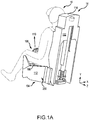
- Ejection seat 14 includes a seat back 102 and a seat pan 104.
- an ejection handle 106 may be located proximate a front 108 of seat 104.
- the seat 104 may house an ejection simulation system 200, in accordance with various embodiments.
- Front 108 of seat pan 104 is generally opposite, or distal, seat back 102. While FIG. 1A shows ejection handle 106 located at front 108 of seat 104, it is further contemplated and understood that ejection handle 106 may be located anywhere that is accessible to an occupant of ejection seat 14.
- ejection seat 14 may allow an occupant (e.g., a trainer pilot), to pull ejection handle 106 and/or experience a simulated force 110 to pull the ejection handle.
- the simulated force may correspond to a typical force a pilot may experience when ejecting from an aircraft.
- an ejection simulation device may release.
- the ejection simulation device may be configured to reset to an initial position after the ejection simulation device has been released.
- the ejection seat 14 may be reused to train pilots for ejection scenarios.
- the ejection simulation system 200 may allow testing of various components of an ejection system, such as the ejection handle 106 and components connected to the ejection simulation device.
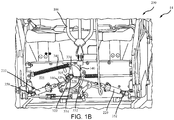
- Ejection seat 14 is illustrated with a cover removed to view the components of an ejection initiation simulation system, in accordance with various embodiments.
- Ejection seat 14 may comprise an ejection simulation system 200, in accordance with various embodiments.
- the ejection sequence initiation simulation system comprises an ejection handle 106 and a first ejection sequence initiation simulation ballistic device 210.
- the first ejection sequence initiation simulation ballistic device 210 may be operably coupled to the ejection handle 106.
- the first ejection simulation device upon pulling the ejection handle 106, the first ejection simulation device may be released and/or simulate a force for pulling an ejection handle 106 in an ejection seat of an aircraft.
- the first ejection sequence initiation simulation ballistic device 210 may be coupled to a fork flange 322 of a mount 320 pivotable about a fulcrum 305.
- the mount 320 may be coupled to a lever apparatus 330 and the seat pan 104.
- the lever apparatus 330 may comprise a first lever 332 extending from the fulcrum 305 and a second lever 334 extending from the fulcrum 305.
- the first lever 332 may be coupled to the ejection handle 106 by a cable 305, or the like.
- the cable 305 may be coupled to the first lever 332 at a radial distance from the fulcrum 305.
- the lever apparatus 330 may comprise a moment arm from the fulcrum 305.
- the second lever 334 may extend from the fulcrum 305 radially outward.
- the second lever 334 may be coupled to the seat pan 104 via a spring 340, or the like.
- the spring 340 may compress upon pulling the ejection handle 106 and return to an initial position upon activation of the first ejection sequence initiation simulation ballistic device 210.
- the mount 320 and the lever apparatus 330 may be configured to rotate together about fulcrum 305. In this regard, as lever apparatus 330 rotates, mount 320 may rotate, and rod 310 may pull away from first ejection sequence initiation simulation ballistic device 210 until first ejection sequence initiation simulation ballistic device 210 is activated, at which point the spring 340 may force the lever apparatus back to its initial position.
- the ejection simulation system 200 may further comprise a second ejection sequence simulation ballistic device 220 disposed opposite the first ejection sequence initiation simulation ballistic device 210
- the second ejection sequence simulation ballistic device 220 may be provided to simulate a redundant ejection device of a typical ejection system for an aircraft.
- the second ejection sequence simulation ballistic device 220 may be coupled to a second fork flange 324 of the mount 320 by a rod 312.
- both rod 310 and rod 312 may pull away from their respective ejection simulation device (e.g., first ejection sequence initiation simulation ballistic device 210 and second ejection sequence simulation ballistic device 220) until at least one of the ejection sequence simulation ballistic devices 210, 220 activates.
- their respective ejection simulation device e.g., first ejection sequence initiation simulation ballistic device 210 and second ejection sequence simulation ballistic device 220
- the ejection simulation system 200 may further comprise a first conduit 350 and/or a second conduit 360.
- the first conduit 350 may be coupled to the first ejection sequence initiation simulation ballistic device 210.
- the second conduit 352 may be coupled to the second ejection sequence simulation ballistic device 220.
- the first conduit 350 may be fluidly coupled to an ignitor configured to eject evacuation seat 14 in a typical ejection system.
- second conduit 352 may be fluidly coupled to an ignitor configured to eject evacuations seat 14 in a typical ejection system.
- a typical ejection initiator may replace first ejection sequence initiation simulation ballistic device 210 and/or second ejection sequence simulation ballistic device 220, resulting in a typical ejection seat for use in an aircraft.
- first ejection sequence initiation simulation ballistic device 210 and/or the second ejection sequence simulation ballistic device 220 may be in accordance with the mechanical trigger device 400.
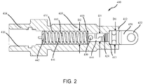
- the mechanical trigger device 400 comprises a housing 410, a sear 420, and a spring 430, and a firing pin 440.
- the housing 410 comprises a first end 412 and a second end 414.
- the first end 412 may include a counterbore 413 extending in an axial direction from the first end 412 to the second end 414.
- the second end 414 may include a counterbore 415 extending in an axial direction toward the first end.
- an aperture extending through the housing 410 may be defined by various diameters.
- housing 410 may define an inner diameter D1, between first end 412 and second end 414, housing 410 may define an inner diameter D2, and between inner diameter D1 and inner diameter D2, housing 410 may define an inner diameter D3.
- D1 may be greater than D3 and D2 may be greater than D3.
- the sear 420 may comprise a coupling end 422, an engagement end 424, and shoulder mating portion 426.
- the coupling end 422 may be configured to be coupled to a rod (e.g., rod 310 or rod 312 from FIG. 1B ).
- the shoulder mating portion 426 may be configured to mate with the counterbore 413 of first end 412 in an assembled state of the mechanical trigger device 400.
- the shoulder mating portion 426 may be disposed between the coupling end and the engagement end.
- the firing pin 440 may comprise a retention end 442, engagement end 444, and an elongated body 446.
- the elongated body 446 may extend from the retention end 442 to the engagement end 444.
- the spring 430 may be wrapped around the elongated body 446 and extend from the retention end 442 to a shoulder defined by counterbore 415. In an assembled state, the spring 430 may be in a neutral position or a compressed state. In various embodiments, in the assembled state, the engagement end 444 of the firing pin 440 may engage the engagement end 424 of the sear 420.
- the sear 420 and the firing pin 440 may move together and/or compress spring 430 between the retention end 442 of the firing pin 440 and the counterbore 415.
- a force to activate a typical ejection initiator may be simulated by pulling ejection handle 106, translating rod 310, and pulling the sear 420 axially away from housing 410.
- second end 414 may be configured to be coupled to a conduit (e.g., first conduit 350 or second conduit 352 from FIG. 1B ).
- second end 414 may comprise a threaded radially inner surface 416.
- the threaded radially inner surface 416 may be configured to be coupled to a threaded radially outer surface of first conduit 350 and/or second conduit 352.
- the mechanical trigger device 400 may further comprise a reset screw 450 coupled to the firing pin 440 proximate the engagement end 444.
- the mechanical trigger device i.e., the sear 420 is pulled and disengages the firing pin 440
- the firing pin 440 may be pulled axially toward counterbore 413, then the engagement end 424 of sear 420 may re-engage the engagement end 444 of the firing pin 440, and the mechanical trigger device 400 may be re-set to the assembled state shown in Fig. 2 .
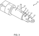
- the housing 410 may further comprise a slot 511.
- the slot 511 may comprise an axial portion 512 and a circumferential portion 513.
- the axial portion 512 may extend from a location proximate counterbore 415 to a location proximate counterbore 413.
- the reset screw 450 may extend radially outward from the firing pin 440 through the slot 511 and outward of the housing 410.
- the reset screw 450 may be pulled axially toward first end 412 of the housing 410 and locked in the circumferential portion of the slot 511.
- the engagement end 444 of the firing pin 440 may be disposed proximate counterbore 413 of the housing to be re-engaged with the engagement end 424 of the sear 420 and re-set to the assembled state shown in FIG. 2 .
- FIG. 4A illustrates the mechanical trigger device 400 in the assembled state.
- the sear 420 may be pulled axially away from the housing 410 and in response, pull the firing pin 440 axially as well.
- the spring 430 may compress against counterbore 415 of the housing 410.
- the engagement end 424 of sear 420 may begin to disengage from the engagement end 444 of the firing pin 440 due to the increase in diameter as shown in FIG. 4C .
- the spring 430 may be fully compressed against the counterbore 415 of the housing 410.
- the spring 430 may bias the firing pin 440 axially away from first end 412 of the housing 410, resulting in the spring 430 in a neutral state within the housing 410.
- the mechanical trigger device 400 during re-assembly is illustrated, in accordance with various embodiments.
- the reset screw 450 may be disposed in the circumferential portion 513 of the slot 511 of the housing 410.
- the engagement end 444 of the firing pin 440 may be disposed in counterbore 413 of the housing.
- the engagement end 424 of the sear 420 may be re-engaged with the engagement end 444 of the firing pin 440, and the mechanical trigger device 400 may be reset to the assembled state by translating the reset screw 450 back to the axial portion 512 of the slot 511 proximate counterbore 415.
- the mechanical trigger device 400 may be resettable for force evaluations of a typical seat ejection system. In various embodiments, the mechanical trigger device 400 may provide a trainer pilot with training as to a force to pull a typical seat ejection system. In various embodiments, the mechanical trigger device 400 may replace an ejection initiator device for a typical seat ejection system for training and/or evaluation of the system.
- references to "various embodiments”, “one embodiment”, “an embodiment”, “an example embodiment”, etc. indicate that the embodiment described may include a particular feature, structure, or characteristic, but every embodiment may not necessarily include the particular feature, structure, or characteristic. Moreover, such phrases are not necessarily referring to the same embodiment. Further, when a particular feature, structure, or characteristic is described in connection with an embodiment, it is submitted that it is within the knowledge of one skilled in the art to affect such feature, structure, or characteristic in connection with other embodiments whether or not explicitly described. After reading the description, it will be apparent to one skilled in the relevant art(s) how to implement the disclosure in alternative embodiments.
Landscapes
- Engineering & Computer Science (AREA)
- Aviation & Aerospace Engineering (AREA)
- Business, Economics & Management (AREA)
- Theoretical Computer Science (AREA)
- Emergency Management (AREA)
- Physics & Mathematics (AREA)
- Educational Administration (AREA)
- Educational Technology (AREA)
- General Physics & Mathematics (AREA)
- Toys (AREA)
- General Engineering & Computer Science (AREA)
- Powder Metallurgy (AREA)
Abstract
Description
- The present disclosure relates to mechanical trigger devices, and more specifically, to mechanical trigger devices configured for re-assembly of a sear and a firing pin.
- Ejection systems are designed to expel pilots from an aircraft cockpit. Ejection seats in high performance aircraft benefit from safely removing the pilot or other occupant from the disabled aircraft across a wide variety of aircraft speed regimes, altitudes and aircraft attitudes. Occupants of aircrafts may never exert an amount of force to pull an evacuation handle, unless the occupant experiences an event where the pilot is ejected from the aircraft.
- A mechanical trigger device is disclosed herein. The mechanical trigger device may comprise: a housing having a slot disposed therethrough; a firing pin disposed in the housing; a spring wrapped around the firing pin; and a reset screw extending radially outward through the firing pin, the reset screw configured to hold the firing pin in a fixed position against a force of the spring.
- In various embodiments, the slot may comprise an axial portion and a circumferential portion. The housing may comprise a first counterbore disposed at a first end of the housing extending axially through the housing and a second counterbore disposed axially opposite the first counterbore. The firing pin may comprise a retention end and a firing pin engagement end, and the spring is disposed between the retention end and the second counterbore. The mechanical trigger device may further comprise a sear configured to engage the firing pin, wherein the sear may comprise a sear engagement end configured to engage the firing pin engagement end. The first end may be configured to receive the sear, and a second end of the housing may be configured to be coupled to a conduit. The sear may be configured to disengage and re-engage the firing pin.
- An ejection seat ejection initiation force simulation system is disclosed herein. The ejection seat ejection initiation force simulation system may comprise: an ejection handle; and a mechanical trigger device operably coupled to the ejection handle, the mechanical trigger device configured to release in response to pulling the ejection handle, the mechanical trigger device configured to be re-set to an assembled state after pulling the ejection handle.
- In various embodiments, the mechanical trigger device may comprise a reset screw coupled to a firing pin, wherein the firing pin is disposed in a housing of the mechanical trigger device, and wherein the reset screw is configured to hold the firing pin in a fixed position against a force of the spring. The ejection imitator simulation device may further comprise a conduit and a rod, wherein the rod is coupled to a sear of the mechanical trigger device, and wherein the conduit is coupled to a second end of the mechanical trigger device. The rod may be configured to translate the sear away from a housing of the mechanical trigger device in response to pulling of the ejection handle. The sear may comprise a sear engagement end, wherein the mechanical trigger device further comprises a firing pin having a firing pin engagement end, and wherein the firing pin engagement end engages the sear engagement end in the assembled state. The mechanical trigger device may further comprise a spring disposed around the firing pin. The mechanical trigger device may comprise a housing and a reset screw, wherein a slot is disposed in the housing, wherein the slot includes an axial portion and a circumferential portion, and wherein the reset screw extends radially outward from the slot. The reset screw may be coupled to a firing pin of the mechanical trigger device. The mechanical trigger device may comprise: a housing having a slot disposed therethrough; a firing pin disposed in the housing; a spring wrapped around the firing pin; a sear configured to engage the firing pin; and a reset screw extending radially outward through the firing pin, the reset screw the reset screw configured to hold the firing pin in a fixed position against a force of the spring. The mechanical trigger device may further comprise a conduit and a rod, wherein the rod is coupled to the sear, and wherein the conduit is operably coupled to the ejection handle. The conduit may be in fluid communication with an ignitor.
- A method of using an mechanical trigger device is disclosed herein. The method may comprise: releasing a sear of the mechanical trigger device from engagement with a firing pin; translating the firing pin proximate a first counterbore at a first end of a housing; re-engaging the sear with the firing pin; and translating the firing pin and the sear away from the first end proximate a second counterbore of the housing.
- In various embodiments, the method may further comprise re-releasing the sear from engagement with the firing pin.
- The foregoing features and elements may be combined in various combinations without exclusivity, unless expressly indicated otherwise. These features and elements as well as the operation thereof will become more apparent in light of the following description and the accompanying drawings. It should be understood, however, the following description and drawings are intended to be exemplary in nature and nonlimiting.
- The subject matter of the present disclosure is particularly pointed out and distinctly claimed in the concluding portion of the specification. A more complete understanding of the present disclosure, however, may best be obtained by referring to the detailed description and claims when considered in connection with the following illustrative figures. In the following figures, like reference numbers refer to similar elements and steps throughout the figures.
-
FIG. 1A illustrates an ejection seat, in accordance with various embodiments; -
FIG. 1B illustrates an ejection seat having an ejection simulation system, in accordance with various embodiments; -
FIG. 2 illustrates a cross-sectional view of an mechanical trigger device, in accordance with various embodiments; -
FIG. 3 illustrates a perspective view of an mechanical trigger device, in accordance with various embodiments; -
FIGs. 4A, 4B ,4C, and 4D illustrate an mechanical trigger device in use, in accordance with various embodiments; and -
FIG. 5 illustrates a perspective view of an mechanical trigger device in during re-assembly, in accordance with various embodiments. - The detailed description of exemplary embodiments herein makes reference to the accompanying drawings, which show exemplary embodiments by way of illustration. While these exemplary embodiments are described in sufficient detail to enable those skilled in the art to practice the disclosures, it should be understood that other embodiments may be realized and that logical changes and adaptations in design and construction may be made in accordance with this disclosure and the teachings herein. Thus, the detailed description herein is presented for purposes of illustration only and not of limitation.
- The scope of the disclosure is defined by the appended claims and their legal equivalents rather than by merely the examples described. For example, the steps recited in any of the method or process descriptions may be executed in any order and are not necessarily limited to the order presented. Furthermore, any reference to singular includes plural embodiments, and any reference to more than one component or step may include a singular embodiment or step. Also, any reference to tacked, attached, fixed, coupled, connected or the like may include permanent, removable, temporary, partial, full and/or any other possible attachment option. Additionally, any reference to without contact (or similar phrases) may also include reduced contact or minimal contact. Surface shading lines may be used throughout the figures to denote different parts but not necessarily to denote the same or different materials.
- A mechanical trigger device is disclosed herein. The mechanical trigger device may include a sear that may be removably coupled to a firing pin. The mechanical trigger device may be configured to release the firing pin by decoupling the sear from the firing pin. The mechanical trigger device may further be configured to be re-set to a loaded position by holding the firing pin against a spring force to allow re-coupling of the sear to the firing pin. In this regard, the mechanical trigger device may be used in any mechanical trigger system, such as ejection seat application including emergency backup batteries, drogue parachutes, recovery parachute reefing line cutters, and non-ejection seat applications including sear devices. Although this application is disclosed with respect to an ejection simulation system, any system where the desire is to re-use the mechanical trigger for purposes of simulation of sear actuation forces or any other purpose needing re-use of a sear trigger is within the scope of this disclosure.
- Referring now to
FIG. 1A ,ejection seat 14 is illustrated, in accordance with various embodiments.Ejection seat 14 includes aseat back 102 and aseat pan 104. In various embodiments, anejection handle 106 may be located proximate afront 108 ofseat 104. Theseat 104 may house anejection simulation system 200, in accordance with various embodiments.Front 108 ofseat pan 104 is generally opposite, or distal, seat back 102. WhileFIG. 1A shows ejection handle 106 located atfront 108 ofseat 104, it is further contemplated and understood that ejection handle 106 may be located anywhere that is accessible to an occupant ofejection seat 14. In various embodiments,ejection seat 14 may allow an occupant (e.g., a trainer pilot), to pull ejection handle 106 and/or experience asimulated force 110 to pull the ejection handle. The simulated force may correspond to a typical force a pilot may experience when ejecting from an aircraft. Upon pullingejection handle 106, an ejection simulation device may release. The ejection simulation device may be configured to reset to an initial position after the ejection simulation device has been released. In this regard, theejection seat 14 may be reused to train pilots for ejection scenarios. In various embodiments, theejection simulation system 200 may allow testing of various components of an ejection system, such as the ejection handle 106 and components connected to the ejection simulation device. - Referring now to
FIG. 1B ,ejection seat 14 is illustrated with a cover removed to view the components of an ejection initiation simulation system, in accordance with various embodiments.Ejection seat 14 may comprise anejection simulation system 200, in accordance with various embodiments. In various embodiments, the ejection sequence initiation simulation system comprises anejection handle 106 and a first ejection sequence initiation simulationballistic device 210. The first ejection sequence initiation simulationballistic device 210 may be operably coupled to theejection handle 106. In this regard, upon pulling theejection handle 106, the first ejection simulation device may be released and/or simulate a force for pulling anejection handle 106 in an ejection seat of an aircraft. - For example, the first ejection sequence initiation simulation
ballistic device 210 may be coupled to afork flange 322 of a mount 320 pivotable about afulcrum 305. The mount 320 may be coupled to alever apparatus 330 and theseat pan 104. Thelever apparatus 330 may comprise afirst lever 332 extending from thefulcrum 305 and asecond lever 334 extending from thefulcrum 305. Thefirst lever 332 may be coupled to the ejection handle 106 by acable 305, or the like. Thecable 305 may be coupled to thefirst lever 332 at a radial distance from thefulcrum 305. In this regard, thelever apparatus 330 may comprise a moment arm from thefulcrum 305. Similarly, thesecond lever 334 may extend from thefulcrum 305 radially outward. Thesecond lever 334 may be coupled to theseat pan 104 via aspring 340, or the like. Thespring 340 may compress upon pulling the ejection handle 106 and return to an initial position upon activation of the first ejection sequence initiation simulationballistic device 210. The mount 320 and thelever apparatus 330 may be configured to rotate together aboutfulcrum 305. In this regard, aslever apparatus 330 rotates, mount 320 may rotate, and rod 310 may pull away from first ejection sequence initiation simulationballistic device 210 until first ejection sequence initiation simulationballistic device 210 is activated, at which point thespring 340 may force the lever apparatus back to its initial position. - In various embodiments, the
ejection simulation system 200 may further comprise a second ejection sequence simulationballistic device 220 disposed opposite the first ejection sequence initiation simulationballistic device 210 In this regard, the second ejection sequence simulationballistic device 220 may be provided to simulate a redundant ejection device of a typical ejection system for an aircraft. The second ejection sequence simulationballistic device 220 may be coupled to a second fork flange 324 of the mount 320 by a rod 312. In this regard, as the mount 320 rotates about thefulcrum 305, both rod 310 and rod 312 may pull away from their respective ejection simulation device (e.g., first ejection sequence initiation simulationballistic device 210 and second ejection sequence simulation ballistic device 220) until at least one of the ejection sequence simulationballistic devices - In various embodiments, the
ejection simulation system 200 may further comprise afirst conduit 350 and/or a second conduit 360. Thefirst conduit 350 may be coupled to the first ejection sequence initiation simulationballistic device 210. Similarly, thesecond conduit 352 may be coupled to the second ejection sequence simulationballistic device 220. Thefirst conduit 350 may be fluidly coupled to an ignitor configured to ejectevacuation seat 14 in a typical ejection system. Similarly,second conduit 352 may be fluidly coupled to an ignitor configured to ejectevacuations seat 14 in a typical ejection system. In this regard, a typical ejection initiator may replace first ejection sequence initiation simulationballistic device 210 and/or second ejection sequence simulationballistic device 220, resulting in a typical ejection seat for use in an aircraft. - Referring now to
FIG. 2 , a cross-sectional view of a mechanical trigger device in an assembled state, in accordance with various embodiments, is illustrated. In various embodiments, first ejection sequence initiation simulationballistic device 210 and/or the second ejection sequence simulationballistic device 220 may be in accordance with themechanical trigger device 400. In various embodiments, themechanical trigger device 400 comprises ahousing 410, a sear 420, and aspring 430, and afiring pin 440. Thehousing 410 comprises afirst end 412 and asecond end 414. Thefirst end 412 may include acounterbore 413 extending in an axial direction from thefirst end 412 to thesecond end 414. Similarly, thesecond end 414 may include acounterbore 415 extending in an axial direction toward the first end. In this regard, an aperture extending through thehousing 410 may be defined by various diameters. For example, proximate thefirst end 412,housing 410 may define an inner diameter D1, betweenfirst end 412 andsecond end 414,housing 410 may define an inner diameter D2, and between inner diameter D1 and inner diameter D2,housing 410 may define an inner diameter D3. In various embodiments, D1 may be greater than D3 and D2 may be greater than D3. - In various embodiments, the sear 420 may comprise a
coupling end 422, anengagement end 424, and shoulder mating portion 426. Thecoupling end 422 may be configured to be coupled to a rod (e.g., rod 310 or rod 312 fromFIG. 1B ). The shoulder mating portion 426 may be configured to mate with thecounterbore 413 offirst end 412 in an assembled state of themechanical trigger device 400. The shoulder mating portion 426 may be disposed between the coupling end and the engagement end. - In various embodiments, the
firing pin 440 may comprise aretention end 442,engagement end 444, and anelongated body 446. Theelongated body 446 may extend from theretention end 442 to theengagement end 444. Thespring 430 may be wrapped around theelongated body 446 and extend from theretention end 442 to a shoulder defined bycounterbore 415. In an assembled state, thespring 430 may be in a neutral position or a compressed state. In various embodiments, in the assembled state, theengagement end 444 of thefiring pin 440 may engage theengagement end 424 of the sear 420. In this regard, as the sear 420 translates axially away from thehousing 410, the sear 420 and thefiring pin 440 may move together and/or compressspring 430 between theretention end 442 of thefiring pin 440 and thecounterbore 415. As such, with combine reference toFIG. 1B andFIG 2 , a force to activate a typical ejection initiator may be simulated by pullingejection handle 106, translating rod 310, and pulling the sear 420 axially away fromhousing 410. - In various embodiments,
second end 414 may be configured to be coupled to a conduit (e.g.,first conduit 350 orsecond conduit 352 fromFIG. 1B ). For example,second end 414 may comprise a threaded radiallyinner surface 416. The threaded radiallyinner surface 416 may be configured to be coupled to a threaded radially outer surface offirst conduit 350 and/orsecond conduit 352. - In various embodiments, the
mechanical trigger device 400 may further comprise areset screw 450 coupled to thefiring pin 440 proximate theengagement end 444. In this regard, after the mechanical trigger device is used (i.e., the sear 420 is pulled and disengages thefiring pin 440, thefiring pin 440 may be pulled axially towardcounterbore 413, then theengagement end 424 ofsear 420 may re-engage theengagement end 444 of thefiring pin 440, and themechanical trigger device 400 may be re-set to the assembled state shown inFig. 2 . - Referring now to
FIG. 3 , a perspective view of themechanical trigger device 400, in accordance with various embodiments, is illustrated. Thehousing 410 may further comprise aslot 511. Theslot 511 may comprise anaxial portion 512 and acircumferential portion 513. With combined reference toFIGs. 2 and3 , theaxial portion 512 may extend from a locationproximate counterbore 415 to a locationproximate counterbore 413. Thereset screw 450 may extend radially outward from thefiring pin 440 through theslot 511 and outward of thehousing 410. In this regard, after themechanical trigger device 400 is used and the sear 420 is separated from the housing, thereset screw 450 may be pulled axially towardfirst end 412 of thehousing 410 and locked in the circumferential portion of theslot 511. In this regard, theengagement end 444 of thefiring pin 440 may be disposedproximate counterbore 413 of the housing to be re-engaged with theengagement end 424 of the sear 420 and re-set to the assembled state shown inFIG. 2 . - For example, referring now to
FIGs. 4A-4D , themechanical trigger device 400 in use is illustrated, in accordance with various embodiments.FIG. 4A illustrates themechanical trigger device 400 in the assembled state. With combined reference toFIGs. 4B andFIG. 2 , as the ejection handle 106 is pulled, the sear 420 may be pulled axially away from thehousing 410 and in response, pull thefiring pin 440 axially as well. In response, thespring 430 may compress againstcounterbore 415 of thehousing 410. Upon theengagement end 444 of thefiring pin 440 and theengagement end 424 of the sear 420 reaching thecounterbore 413 atfirst end 412 of thehousing 410, theengagement end 424 ofsear 420 may begin to disengage from theengagement end 444 of thefiring pin 440 due to the increase in diameter as shown inFIG. 4C . At this stage, thespring 430 may be fully compressed against thecounterbore 415 of thehousing 410. With reference now toFIG. 4D , After the sear 420 releases from thefiring pin 440, thespring 430 may bias thefiring pin 440 axially away fromfirst end 412 of thehousing 410, resulting in thespring 430 in a neutral state within thehousing 410. - Referring now to
FIG. 5 , themechanical trigger device 400 during re-assembly is illustrated, in accordance with various embodiments. During re-assembly, thereset screw 450 may be disposed in thecircumferential portion 513 of theslot 511 of thehousing 410. In this regard, with brief reference toFIG. 4C , theengagement end 444 of thefiring pin 440 may be disposed incounterbore 413 of the housing. As such, theengagement end 424 of the sear 420 may be re-engaged with theengagement end 444 of thefiring pin 440, and themechanical trigger device 400 may be reset to the assembled state by translating thereset screw 450 back to theaxial portion 512 of theslot 511proximate counterbore 415. - In various embodiments, the
mechanical trigger device 400 may be resettable for force evaluations of a typical seat ejection system. In various embodiments, themechanical trigger device 400 may provide a trainer pilot with training as to a force to pull a typical seat ejection system. In various embodiments, themechanical trigger device 400 may replace an ejection initiator device for a typical seat ejection system for training and/or evaluation of the system. - Benefits, other advantages, and solutions to problems have been described herein with regard to specific embodiments. Furthermore, the connecting lines shown in the various figures contained herein are intended to represent exemplary functional relationships and/or physical couplings between the various elements. It should be noted that many alternative or additional functional relationships or physical connections may be present in a practical system. However, the benefits, advantages, solutions to problems, and any elements that may cause any benefit, advantage, or solution to occur or become more pronounced are not to be construed as critical, required, or essential features or elements of the disclosures. The scope of the disclosures is accordingly to be limited by nothing other than the appended claims and their legal equivalents, in which reference to an element in the singular is not intended to mean "one and only one" unless explicitly so stated, but rather "one or more." Moreover, where a phrase similar to "at least one of A, B, or C" is used in the claims, it is intended that the phrase be interpreted to mean that A alone may be present in an embodiment, B alone may be present in an embodiment, C alone may be present in an embodiment, or that any combination of the elements A, B and C may be present in a single embodiment; for example, A and B, A and C, B and C, or A and B and C.
- Systems, methods and apparatus are provided herein. In the detailed description herein, references to "various embodiments", "one embodiment", "an embodiment", "an example embodiment", etc., indicate that the embodiment described may include a particular feature, structure, or characteristic, but every embodiment may not necessarily include the particular feature, structure, or characteristic. Moreover, such phrases are not necessarily referring to the same embodiment. Further, when a particular feature, structure, or characteristic is described in connection with an embodiment, it is submitted that it is within the knowledge of one skilled in the art to affect such feature, structure, or characteristic in connection with other embodiments whether or not explicitly described. After reading the description, it will be apparent to one skilled in the relevant art(s) how to implement the disclosure in alternative embodiments.
- Furthermore, no element, component, or method step in the present disclosure is intended to be dedicated to the public regardless of whether the element, component, or method step is explicitly recited in the claims. As used herein, the terms "comprises", "comprising", or any other variation thereof, are intended to cover a non-exclusive inclusion, such that a process, method, article, or apparatus that comprises a list of elements does not include only those elements but may include other elements not expressly listed or inherent to such process, method, article, or apparatus.
Claims (15)
- A mechanical trigger device (400), comprising:a housing (410) having a slot (511) disposed therethrough;a firing pin (440) disposed in the housing;a spring (430) wrapped around the firing pin; anda reset screw (450) extending radially outward through the firing pin (440), the reset screw hold configured to hold the firing pin in a fixed position against a force of the spring to allow a sear (420) to re-engage the firing pin.
- The mechanical trigger device of claim 1, wherein the slot (511) comprises an axial portion and a circumferential portion.
- The mechanical trigger device of claim 1 or 2, wherein the housing (410) comprises a first counterbore (413) disposed at a first end of the housing extending axially through the housing and a second counterbore (415) disposed axially opposite the first counterbore.
- The mechanical trigger device of claim 3, wherein the firing pin (440) comprises a retention end (442) and a firing pin engagement end (444), and wherein the spring (430) is disposed between the retention end and the second counterbore, and preferably further comprising the sear (420) configured to engage the firing pin (440), wherein the sear comprises a sear engagement end configured to engage the firing pin engagement end.
- The mechanical trigger device of claim 4, wherein the first end is configured to receive the sear (420), and wherein a second end of the housing is configured to be coupled to a conduit; and/or wherein the sear (420) is configured to disengage and re-engage the firing pin (440).
- An ejection seat ejection initiation force simulation system, comprising:an ejection handle (106); anda mechanical trigger device (400) operably coupled to the ejection handle, the mechanical trigger device configured to release in response to pulling the ejection handle, the mechanical trigger device configured to be re-set to an assembled state after pulling the ejection handle.
- The ejection seat ejection initiation force simulation system of claim 6, wherein the mechanical trigger device (400) comprises a reset screw (450) coupled to a firing pin (440), wherein the firing pin is disposed in a housing (410) of the mechanical trigger device, and wherein the reset screw hold configured to hold the firing pin (440) in a fixed position against a force of the spring to allow a sear (420) to re-engage the firing pin.
- The ejection seat ejection initiation force simulation system of claim 6 or 7, further comprising a conduit and a rod, wherein the rod is coupled to a sear (420) of the mechanical trigger device, and wherein the conduit is coupled to a second end of the mechanical trigger device (400).
- The ejection seat ejection initiation force simulation system of claim 8, wherein the rod is configured to translate the sear (420) away from a housing of the mechanical trigger device in response to pulling of the ejection handle (106).
- The ejection seat ejection initiation force simulation system of claim 8, wherein the sear (420) comprises a sear engagement end, wherein the mechanical trigger device (400) further comprises a firing pin (440) having a firing pin engagement end, and wherein the firing pin engagement end engages the sear engagement end in the assembled state, and preferably wherein the mechanical trigger device further comprises a spring (430) disposed around the firing pin.
- The ejection seat ejection initiation force simulation system of claim 6, wherein the mechanical trigger device comprises a housing (410) and a reset screw (450), wherein a slot (511) is disposed in the housing, wherein the slot includes an axial portion and a circumferential portion, and wherein the reset screw extends radially outward from the slot, and preferably wherein the reset screw is coupled to a firing pin of the mechanical trigger device.
- The ejection seat ejection initiation force simulation system of claim 6, wherein the mechanical trigger device comprises:a housing (410) having a slot (511) disposed therethrough;a firing pin (440) disposed in the housing;a spring (430) wrapped around the firing pin;a sear (420) configured to engage the firing pin; anda reset screw (450) extending radially outward through the firing pin, the reset screw hold configured to hold the firing pin in a fixed position against a force of the spring to allow a sear to re-engage the firing pin.
- The ejection seat ejection initiation force simulation system of claim 16, further comprising a conduit and a rod, wherein the rod is coupled to the sear, and wherein the conduit is operably coupled to the ejection handle, and preferably wherein the conduit is in fluid communication with an ignitor.
- A method of using an ejection initiator force simulation device, the method comprising:releasing a sear of the mechanical trigger device from engagement with a firing pin;translating the firing pin proximate a first counterbore at a first end of a housing;re-engaging the sear with the firing pin; andtranslating the firing pin and the sear away from the first end proximate a second counterbore of the housing.
- The method of claim 14, further comprising re-releasing the sear from engagement with the firing pin.
Applications Claiming Priority (1)
| Application Number | Priority Date | Filing Date | Title |
|---|---|---|---|
| US16/824,437 US11935432B2 (en) | 2020-03-19 | 2020-03-19 | Mechanical trigger device and methods thereof |
Publications (2)
| Publication Number | Publication Date |
|---|---|
| EP3882155A1 true EP3882155A1 (en) | 2021-09-22 |
| EP3882155B1 EP3882155B1 (en) | 2023-08-30 |
Family
ID=75108167
Family Applications (1)
| Application Number | Title | Priority Date | Filing Date |
|---|---|---|---|
| EP21163367.2A Active EP3882155B1 (en) | 2020-03-19 | 2021-03-18 | Ejection initiation force simulation system for an ejection seat and methods thereof |
Country Status (2)
| Country | Link |
|---|---|
| US (1) | US11935432B2 (en) |
| EP (1) | EP3882155B1 (en) |
Families Citing this family (1)
| Publication number | Priority date | Publication date | Assignee | Title |
|---|---|---|---|---|
| US12522364B2 (en) * | 2023-08-23 | 2026-01-13 | Rockwell Collins, Inc. | Passive head and neck protection pull handle initiation |
Citations (4)
| Publication number | Priority date | Publication date | Assignee | Title |
|---|---|---|---|---|
| US4028948A (en) * | 1974-09-25 | 1977-06-14 | Frost Engineering Development Corporation | Actuating mechanism for seat restraint divestment system |
| US7762174B1 (en) * | 2007-06-01 | 2010-07-27 | General Dynamics Armament And Technical Products | Ammunition container and feed system |
| CN107813944A (en) * | 2017-11-23 | 2018-03-20 | 航宇救生装备有限公司 | A kind of firing lock |
| WO2018074636A1 (en) * | 2016-10-20 | 2018-04-26 | 주식회사 에이스카이 | Training apparatus and method for emergency escape |
Family Cites Families (3)
| Publication number | Priority date | Publication date | Assignee | Title |
|---|---|---|---|---|
| CN108033018B (en) | 2017-11-21 | 2019-12-03 | 武汉航空仪表有限责任公司 | A kind of ejection escape lockaid gun and its time response adjustment method |
| CN108033035B (en) | 2017-11-24 | 2021-03-26 | 航宇救生装备有限公司 | Seat recovery system for ejection test |
| RU2669720C1 (en) | 2017-12-25 | 2018-10-15 | Акционерное общество "Научно-исследовательский институт "Субмикрон" | Electronic device for aircraft chair |
-
2020
- 2020-03-19 US US16/824,437 patent/US11935432B2/en active Active
-
2021
- 2021-03-18 EP EP21163367.2A patent/EP3882155B1/en active Active
Patent Citations (4)
| Publication number | Priority date | Publication date | Assignee | Title |
|---|---|---|---|---|
| US4028948A (en) * | 1974-09-25 | 1977-06-14 | Frost Engineering Development Corporation | Actuating mechanism for seat restraint divestment system |
| US7762174B1 (en) * | 2007-06-01 | 2010-07-27 | General Dynamics Armament And Technical Products | Ammunition container and feed system |
| WO2018074636A1 (en) * | 2016-10-20 | 2018-04-26 | 주식회사 에이스카이 | Training apparatus and method for emergency escape |
| CN107813944A (en) * | 2017-11-23 | 2018-03-20 | 航宇救生装备有限公司 | A kind of firing lock |
Also Published As
| Publication number | Publication date |
|---|---|
| EP3882155B1 (en) | 2023-08-30 |
| US11935432B2 (en) | 2024-03-19 |
| US20210293501A1 (en) | 2021-09-23 |
Similar Documents
| Publication | Publication Date | Title |
|---|---|---|
| US11300078B2 (en) | Variable thrust catapult | |
| EP1765670B1 (en) | In-flight refueling system and method for facilitating emergency separation of in-flight refueling system components | |
| US10946970B2 (en) | Systems for removal of parachute assembly head restraints | |
| US11935432B2 (en) | Mechanical trigger device and methods thereof | |
| EP3647197A1 (en) | Emergency manual parachute operation system | |
| CA2919505C (en) | Soft cover release mechanism for evacuation slides | |
| US11608183B2 (en) | Automatic ejection time delay system | |
| EP1827979B1 (en) | Aerial refuelling vehicle | |
| WO2010084316A2 (en) | A nozzle for a refuelling probe | |
| EP3488177B1 (en) | Stage separation mechanism and method | |
| EP4140894B1 (en) | Retention systems and methods for ejection seats | |
| EP3738881B1 (en) | Universal sequencer and wire harness assembly for ejection systems | |
| US11565791B2 (en) | Sensor-based ejection initiation system | |
| US3191892A (en) | Ejection seat for aircraft | |
| US11242153B2 (en) | Variable thrust catapult | |
| US20160288914A1 (en) | Apogee enhancing ejection seat stabilization drogue chute | |
| US11434012B2 (en) | Variable thrust catapult | |
| US11345477B2 (en) | Adjustable preload severance cutter for ejection systems | |
| US20220315229A1 (en) | Attenuators for aircraft cable and ejection seat arm restraint assemblies | |
| EP0260354A1 (en) | Discard assembly for parachute deployment mechanism | |
| US11845561B2 (en) | Vertical stabilizer for ejection systems | |
| GB2595571A (en) | Automatic ejection time delay system | |
| US12630293B2 (en) | Reusable releasable restraint for evacuation assemblies | |
| US12522364B2 (en) | Passive head and neck protection pull handle initiation | |
| GB2595364A (en) | Vertical stabilizer for ejection systems |
Legal Events
| Date | Code | Title | Description |
|---|---|---|---|
| PUAI | Public reference made under article 153(3) epc to a published international application that has entered the european phase |
Free format text: ORIGINAL CODE: 0009012 |
|
| STAA | Information on the status of an ep patent application or granted ep patent |
Free format text: STATUS: THE APPLICATION HAS BEEN PUBLISHED |
|
| AK | Designated contracting states |
Kind code of ref document: A1 Designated state(s): AL AT BE BG CH CY CZ DE DK EE ES FI FR GB GR HR HU IE IS IT LI LT LU LV MC MK MT NL NO PL PT RO RS SE SI SK SM TR |
|
| STAA | Information on the status of an ep patent application or granted ep patent |
Free format text: STATUS: REQUEST FOR EXAMINATION WAS MADE |
|
| 17P | Request for examination filed |
Effective date: 20220322 |
|
| RBV | Designated contracting states (corrected) |
Designated state(s): AL AT BE BG CH CY CZ DE DK EE ES FI FR GB GR HR HU IE IS IT LI LT LU LV MC MK MT NL NO PL PT RO RS SE SI SK SM TR |
|
| GRAP | Despatch of communication of intention to grant a patent |
Free format text: ORIGINAL CODE: EPIDOSNIGR1 |
|
| STAA | Information on the status of an ep patent application or granted ep patent |
Free format text: STATUS: GRANT OF PATENT IS INTENDED |
|
| INTG | Intention to grant announced |
Effective date: 20230405 |
|
| GRAS | Grant fee paid |
Free format text: ORIGINAL CODE: EPIDOSNIGR3 |
|
| GRAA | (expected) grant |
Free format text: ORIGINAL CODE: 0009210 |
|
| STAA | Information on the status of an ep patent application or granted ep patent |
Free format text: STATUS: THE PATENT HAS BEEN GRANTED |
|
| AK | Designated contracting states |
Kind code of ref document: B1 Designated state(s): AL AT BE BG CH CY CZ DE DK EE ES FI FR GB GR HR HU IE IS IT LI LT LU LV MC MK MT NL NO PL PT RO RS SE SI SK SM TR |
|
| REG | Reference to a national code |
Ref country code: GB Ref legal event code: FG4D |
|
| REG | Reference to a national code |
Ref country code: CH Ref legal event code: EP |
|
| REG | Reference to a national code |
Ref country code: DE Ref legal event code: R096 Ref document number: 602021004599 Country of ref document: DE |
|
| REG | Reference to a national code |
Ref country code: IE Ref legal event code: FG4D |
|
| P01 | Opt-out of the competence of the unified patent court (upc) registered |
Effective date: 20230922 |
|
| REG | Reference to a national code |
Ref country code: LT Ref legal event code: MG9D |
|
| REG | Reference to a national code |
Ref country code: NL Ref legal event code: MP Effective date: 20230830 |
|
| REG | Reference to a national code |
Ref country code: AT Ref legal event code: MK05 Ref document number: 1605149 Country of ref document: AT Kind code of ref document: T Effective date: 20230830 |
|
| PG25 | Lapsed in a contracting state [announced via postgrant information from national office to epo] |
Ref country code: GR Free format text: LAPSE BECAUSE OF FAILURE TO SUBMIT A TRANSLATION OF THE DESCRIPTION OR TO PAY THE FEE WITHIN THE PRESCRIBED TIME-LIMIT Effective date: 20231201 |
|
| PG25 | Lapsed in a contracting state [announced via postgrant information from national office to epo] |
Ref country code: IS Free format text: LAPSE BECAUSE OF FAILURE TO SUBMIT A TRANSLATION OF THE DESCRIPTION OR TO PAY THE FEE WITHIN THE PRESCRIBED TIME-LIMIT Effective date: 20231230 |
|
| PG25 | Lapsed in a contracting state [announced via postgrant information from national office to epo] |
Ref country code: SE Free format text: LAPSE BECAUSE OF FAILURE TO SUBMIT A TRANSLATION OF THE DESCRIPTION OR TO PAY THE FEE WITHIN THE PRESCRIBED TIME-LIMIT Effective date: 20230830 Ref country code: RS Free format text: LAPSE BECAUSE OF FAILURE TO SUBMIT A TRANSLATION OF THE DESCRIPTION OR TO PAY THE FEE WITHIN THE PRESCRIBED TIME-LIMIT Effective date: 20230830 Ref country code: NO Free format text: LAPSE BECAUSE OF FAILURE TO SUBMIT A TRANSLATION OF THE DESCRIPTION OR TO PAY THE FEE WITHIN THE PRESCRIBED TIME-LIMIT Effective date: 20231130 Ref country code: LV Free format text: LAPSE BECAUSE OF FAILURE TO SUBMIT A TRANSLATION OF THE DESCRIPTION OR TO PAY THE FEE WITHIN THE PRESCRIBED TIME-LIMIT Effective date: 20230830 Ref country code: LT Free format text: LAPSE BECAUSE OF FAILURE TO SUBMIT A TRANSLATION OF THE DESCRIPTION OR TO PAY THE FEE WITHIN THE PRESCRIBED TIME-LIMIT Effective date: 20230830 Ref country code: IS Free format text: LAPSE BECAUSE OF FAILURE TO SUBMIT A TRANSLATION OF THE DESCRIPTION OR TO PAY THE FEE WITHIN THE PRESCRIBED TIME-LIMIT Effective date: 20231230 Ref country code: HR Free format text: LAPSE BECAUSE OF FAILURE TO SUBMIT A TRANSLATION OF THE DESCRIPTION OR TO PAY THE FEE WITHIN THE PRESCRIBED TIME-LIMIT Effective date: 20230830 Ref country code: GR Free format text: LAPSE BECAUSE OF FAILURE TO SUBMIT A TRANSLATION OF THE DESCRIPTION OR TO PAY THE FEE WITHIN THE PRESCRIBED TIME-LIMIT Effective date: 20231201 Ref country code: FI Free format text: LAPSE BECAUSE OF FAILURE TO SUBMIT A TRANSLATION OF THE DESCRIPTION OR TO PAY THE FEE WITHIN THE PRESCRIBED TIME-LIMIT Effective date: 20230830 Ref country code: AT Free format text: LAPSE BECAUSE OF FAILURE TO SUBMIT A TRANSLATION OF THE DESCRIPTION OR TO PAY THE FEE WITHIN THE PRESCRIBED TIME-LIMIT Effective date: 20230830 |
|
| PG25 | Lapsed in a contracting state [announced via postgrant information from national office to epo] |
Ref country code: PL Free format text: LAPSE BECAUSE OF FAILURE TO SUBMIT A TRANSLATION OF THE DESCRIPTION OR TO PAY THE FEE WITHIN THE PRESCRIBED TIME-LIMIT Effective date: 20230830 Ref country code: NL Free format text: LAPSE BECAUSE OF FAILURE TO SUBMIT A TRANSLATION OF THE DESCRIPTION OR TO PAY THE FEE WITHIN THE PRESCRIBED TIME-LIMIT Effective date: 20230830 |
|
| PG25 | Lapsed in a contracting state [announced via postgrant information from national office to epo] |
Ref country code: ES Free format text: LAPSE BECAUSE OF FAILURE TO SUBMIT A TRANSLATION OF THE DESCRIPTION OR TO PAY THE FEE WITHIN THE PRESCRIBED TIME-LIMIT Effective date: 20230830 |
|
| PG25 | Lapsed in a contracting state [announced via postgrant information from national office to epo] |
Ref country code: SM Free format text: LAPSE BECAUSE OF FAILURE TO SUBMIT A TRANSLATION OF THE DESCRIPTION OR TO PAY THE FEE WITHIN THE PRESCRIBED TIME-LIMIT Effective date: 20230830 Ref country code: RO Free format text: LAPSE BECAUSE OF FAILURE TO SUBMIT A TRANSLATION OF THE DESCRIPTION OR TO PAY THE FEE WITHIN THE PRESCRIBED TIME-LIMIT Effective date: 20230830 Ref country code: ES Free format text: LAPSE BECAUSE OF FAILURE TO SUBMIT A TRANSLATION OF THE DESCRIPTION OR TO PAY THE FEE WITHIN THE PRESCRIBED TIME-LIMIT Effective date: 20230830 Ref country code: EE Free format text: LAPSE BECAUSE OF FAILURE TO SUBMIT A TRANSLATION OF THE DESCRIPTION OR TO PAY THE FEE WITHIN THE PRESCRIBED TIME-LIMIT Effective date: 20230830 Ref country code: DK Free format text: LAPSE BECAUSE OF FAILURE TO SUBMIT A TRANSLATION OF THE DESCRIPTION OR TO PAY THE FEE WITHIN THE PRESCRIBED TIME-LIMIT Effective date: 20230830 Ref country code: CZ Free format text: LAPSE BECAUSE OF FAILURE TO SUBMIT A TRANSLATION OF THE DESCRIPTION OR TO PAY THE FEE WITHIN THE PRESCRIBED TIME-LIMIT Effective date: 20230830 Ref country code: PT Free format text: LAPSE BECAUSE OF FAILURE TO SUBMIT A TRANSLATION OF THE DESCRIPTION OR TO PAY THE FEE WITHIN THE PRESCRIBED TIME-LIMIT Effective date: 20240102 Ref country code: SK Free format text: LAPSE BECAUSE OF FAILURE TO SUBMIT A TRANSLATION OF THE DESCRIPTION OR TO PAY THE FEE WITHIN THE PRESCRIBED TIME-LIMIT Effective date: 20230830 |
|
| PG25 | Lapsed in a contracting state [announced via postgrant information from national office to epo] |
Ref country code: IT Free format text: LAPSE BECAUSE OF FAILURE TO SUBMIT A TRANSLATION OF THE DESCRIPTION OR TO PAY THE FEE WITHIN THE PRESCRIBED TIME-LIMIT Effective date: 20230830 |
|
| REG | Reference to a national code |
Ref country code: DE Ref legal event code: R097 Ref document number: 602021004599 Country of ref document: DE |
|
| PLBE | No opposition filed within time limit |
Free format text: ORIGINAL CODE: 0009261 |
|
| STAA | Information on the status of an ep patent application or granted ep patent |
Free format text: STATUS: NO OPPOSITION FILED WITHIN TIME LIMIT |
|
| PG25 | Lapsed in a contracting state [announced via postgrant information from national office to epo] |
Ref country code: SI Free format text: LAPSE BECAUSE OF FAILURE TO SUBMIT A TRANSLATION OF THE DESCRIPTION OR TO PAY THE FEE WITHIN THE PRESCRIBED TIME-LIMIT Effective date: 20230830 |
|
| 26N | No opposition filed |
Effective date: 20240603 |
|
| REG | Reference to a national code |
Ref country code: DE Ref legal event code: R119 Ref document number: 602021004599 Country of ref document: DE |
|
| REG | Reference to a national code |
Ref country code: CH Ref legal event code: PL |
|
| PG25 | Lapsed in a contracting state [announced via postgrant information from national office to epo] |
Ref country code: BG Free format text: LAPSE BECAUSE OF FAILURE TO SUBMIT A TRANSLATION OF THE DESCRIPTION OR TO PAY THE FEE WITHIN THE PRESCRIBED TIME-LIMIT Effective date: 20230830 |
|
| PG25 | Lapsed in a contracting state [announced via postgrant information from national office to epo] |
Ref country code: LU Free format text: LAPSE BECAUSE OF NON-PAYMENT OF DUE FEES Effective date: 20240318 |
|
| PG25 | Lapsed in a contracting state [announced via postgrant information from national office to epo] |
Ref country code: MC Free format text: LAPSE BECAUSE OF FAILURE TO SUBMIT A TRANSLATION OF THE DESCRIPTION OR TO PAY THE FEE WITHIN THE PRESCRIBED TIME-LIMIT Effective date: 20230830 |
|
| PG25 | Lapsed in a contracting state [announced via postgrant information from national office to epo] |
Ref country code: MC Free format text: LAPSE BECAUSE OF FAILURE TO SUBMIT A TRANSLATION OF THE DESCRIPTION OR TO PAY THE FEE WITHIN THE PRESCRIBED TIME-LIMIT Effective date: 20230830 Ref country code: LU Free format text: LAPSE BECAUSE OF NON-PAYMENT OF DUE FEES Effective date: 20240318 Ref country code: BG Free format text: LAPSE BECAUSE OF FAILURE TO SUBMIT A TRANSLATION OF THE DESCRIPTION OR TO PAY THE FEE WITHIN THE PRESCRIBED TIME-LIMIT Effective date: 20230830 |
|
| REG | Reference to a national code |
Ref country code: BE Ref legal event code: MM Effective date: 20240331 |
|
| PG25 | Lapsed in a contracting state [announced via postgrant information from national office to epo] |
Ref country code: DE Free format text: LAPSE BECAUSE OF NON-PAYMENT OF DUE FEES Effective date: 20241001 |
|
| PG25 | Lapsed in a contracting state [announced via postgrant information from national office to epo] |
Ref country code: BE Free format text: LAPSE BECAUSE OF NON-PAYMENT OF DUE FEES Effective date: 20240331 |
|
| PG25 | Lapsed in a contracting state [announced via postgrant information from national office to epo] |
Ref country code: IE Free format text: LAPSE BECAUSE OF NON-PAYMENT OF DUE FEES Effective date: 20240318 |
|
| PG25 | Lapsed in a contracting state [announced via postgrant information from national office to epo] |
Ref country code: IE Free format text: LAPSE BECAUSE OF NON-PAYMENT OF DUE FEES Effective date: 20240318 Ref country code: DE Free format text: LAPSE BECAUSE OF NON-PAYMENT OF DUE FEES Effective date: 20241001 Ref country code: BE Free format text: LAPSE BECAUSE OF NON-PAYMENT OF DUE FEES Effective date: 20240331 Ref country code: CH Free format text: LAPSE BECAUSE OF NON-PAYMENT OF DUE FEES Effective date: 20240331 |
|
| PG25 | Lapsed in a contracting state [announced via postgrant information from national office to epo] |
Ref country code: CY Free format text: LAPSE BECAUSE OF FAILURE TO SUBMIT A TRANSLATION OF THE DESCRIPTION OR TO PAY THE FEE WITHIN THE PRESCRIBED TIME-LIMIT; INVALID AB INITIO Effective date: 20210318 |
|
| PG25 | Lapsed in a contracting state [announced via postgrant information from national office to epo] |
Ref country code: HU Free format text: LAPSE BECAUSE OF FAILURE TO SUBMIT A TRANSLATION OF THE DESCRIPTION OR TO PAY THE FEE WITHIN THE PRESCRIBED TIME-LIMIT; INVALID AB INITIO Effective date: 20210318 |
|
| PG25 | Lapsed in a contracting state [announced via postgrant information from national office to epo] |
Ref country code: TR Free format text: LAPSE BECAUSE OF FAILURE TO SUBMIT A TRANSLATION OF THE DESCRIPTION OR TO PAY THE FEE WITHIN THE PRESCRIBED TIME-LIMIT Effective date: 20230830 |
|
| PGFP | Annual fee paid to national office [announced via postgrant information from national office to epo] |
Ref country code: GB Payment date: 20260219 Year of fee payment: 6 |
|
| PGFP | Annual fee paid to national office [announced via postgrant information from national office to epo] |
Ref country code: FR Payment date: 20260220 Year of fee payment: 6 |