EP3882137A1 - Magnetic self-centering shimmy damper - Google Patents
Magnetic self-centering shimmy damper Download PDFInfo
- Publication number
- EP3882137A1 EP3882137A1 EP21163709.5A EP21163709A EP3882137A1 EP 3882137 A1 EP3882137 A1 EP 3882137A1 EP 21163709 A EP21163709 A EP 21163709A EP 3882137 A1 EP3882137 A1 EP 3882137A1
- Authority
- EP
- European Patent Office
- Prior art keywords
- damper
- cap
- magnet
- shaft
- housing
- Prior art date
- Legal status (The legal status is an assumption and is not a legal conclusion. Google has not performed a legal analysis and makes no representation as to the accuracy of the status listed.)
- Granted
Links
Images



Classifications
-
- B—PERFORMING OPERATIONS; TRANSPORTING
- B64—AIRCRAFT; AVIATION; COSMONAUTICS
- B64C—AEROPLANES; HELICOPTERS
- B64C25/00—Alighting gear
- B64C25/02—Undercarriages
-
- B—PERFORMING OPERATIONS; TRANSPORTING
- B64—AIRCRAFT; AVIATION; COSMONAUTICS
- B64C—AEROPLANES; HELICOPTERS
- B64C25/00—Alighting gear
- B64C25/32—Alighting gear characterised by elements which contact the ground or similar surface
- B64C25/50—Steerable undercarriages; Shimmy-damping
- B64C25/505—Shimmy damping
-
- F—MECHANICAL ENGINEERING; LIGHTING; HEATING; WEAPONS; BLASTING
- F16—ENGINEERING ELEMENTS AND UNITS; GENERAL MEASURES FOR PRODUCING AND MAINTAINING EFFECTIVE FUNCTIONING OF MACHINES OR INSTALLATIONS; THERMAL INSULATION IN GENERAL
- F16C—SHAFTS; FLEXIBLE SHAFTS; ELEMENTS OR CRANKSHAFT MECHANISMS; ROTARY BODIES OTHER THAN GEARING ELEMENTS; BEARINGS
- F16C32/00—Bearings not otherwise provided for
- F16C32/04—Bearings not otherwise provided for using magnetic or electric supporting means
- F16C32/0406—Magnetic bearings
- F16C32/0408—Passive magnetic bearings
- F16C32/0423—Passive magnetic bearings with permanent magnets on both parts repelling each other
- F16C32/0427—Passive magnetic bearings with permanent magnets on both parts repelling each other for axial load mainly
-
- F—MECHANICAL ENGINEERING; LIGHTING; HEATING; WEAPONS; BLASTING
- F16—ENGINEERING ELEMENTS AND UNITS; GENERAL MEASURES FOR PRODUCING AND MAINTAINING EFFECTIVE FUNCTIONING OF MACHINES OR INSTALLATIONS; THERMAL INSULATION IN GENERAL
- F16F—SPRINGS; SHOCK-ABSORBERS; MEANS FOR DAMPING VIBRATION
- F16F15/00—Suppression of vibrations in systems; Means or arrangements for avoiding or reducing out-of-balance forces, e.g. due to motion
- F16F15/02—Suppression of vibrations of non-rotating, e.g. reciprocating systems; Suppression of vibrations of rotating systems by use of members not moving with the rotating systems
- F16F15/03—Suppression of vibrations of non-rotating, e.g. reciprocating systems; Suppression of vibrations of rotating systems by use of members not moving with the rotating systems using magnetic or electromagnetic means
-
- F—MECHANICAL ENGINEERING; LIGHTING; HEATING; WEAPONS; BLASTING
- F16—ENGINEERING ELEMENTS AND UNITS; GENERAL MEASURES FOR PRODUCING AND MAINTAINING EFFECTIVE FUNCTIONING OF MACHINES OR INSTALLATIONS; THERMAL INSULATION IN GENERAL
- F16F—SPRINGS; SHOCK-ABSORBERS; MEANS FOR DAMPING VIBRATION
- F16F6/00—Magnetic springs; Fluid magnetic springs, i.e. magnetic spring combined with a fluid
- F16F6/005—Magnetic springs; Fluid magnetic springs, i.e. magnetic spring combined with a fluid using permanent magnets only
-
- B—PERFORMING OPERATIONS; TRANSPORTING
- B64—AIRCRAFT; AVIATION; COSMONAUTICS
- B64C—AEROPLANES; HELICOPTERS
- B64C25/00—Alighting gear
- B64C25/001—Devices not provided for in the groups B64C25/02 - B64C25/68
- B64C2025/003—Means for reducing landing gear noise, or turbulent flow around it, e.g. landing gear doors used as deflectors
-
- F—MECHANICAL ENGINEERING; LIGHTING; HEATING; WEAPONS; BLASTING
- F16—ENGINEERING ELEMENTS AND UNITS; GENERAL MEASURES FOR PRODUCING AND MAINTAINING EFFECTIVE FUNCTIONING OF MACHINES OR INSTALLATIONS; THERMAL INSULATION IN GENERAL
- F16C—SHAFTS; FLEXIBLE SHAFTS; ELEMENTS OR CRANKSHAFT MECHANISMS; ROTARY BODIES OTHER THAN GEARING ELEMENTS; BEARINGS
- F16C2326/00—Articles relating to transporting
- F16C2326/43—Aeroplanes; Helicopters
-
- F—MECHANICAL ENGINEERING; LIGHTING; HEATING; WEAPONS; BLASTING
- F16—ENGINEERING ELEMENTS AND UNITS; GENERAL MEASURES FOR PRODUCING AND MAINTAINING EFFECTIVE FUNCTIONING OF MACHINES OR INSTALLATIONS; THERMAL INSULATION IN GENERAL
- F16F—SPRINGS; SHOCK-ABSORBERS; MEANS FOR DAMPING VIBRATION
- F16F2222/00—Special physical effects, e.g. nature of damping effects
- F16F2222/06—Magnetic or electromagnetic
-
- F—MECHANICAL ENGINEERING; LIGHTING; HEATING; WEAPONS; BLASTING
- F16—ENGINEERING ELEMENTS AND UNITS; GENERAL MEASURES FOR PRODUCING AND MAINTAINING EFFECTIVE FUNCTIONING OF MACHINES OR INSTALLATIONS; THERMAL INSULATION IN GENERAL
- F16F—SPRINGS; SHOCK-ABSORBERS; MEANS FOR DAMPING VIBRATION
- F16F2222/00—Special physical effects, e.g. nature of damping effects
- F16F2222/12—Fluid damping
-
- F—MECHANICAL ENGINEERING; LIGHTING; HEATING; WEAPONS; BLASTING
- F16—ENGINEERING ELEMENTS AND UNITS; GENERAL MEASURES FOR PRODUCING AND MAINTAINING EFFECTIVE FUNCTIONING OF MACHINES OR INSTALLATIONS; THERMAL INSULATION IN GENERAL
- F16F—SPRINGS; SHOCK-ABSORBERS; MEANS FOR DAMPING VIBRATION
- F16F2232/00—Nature of movement
- F16F2232/02—Rotary
-
- F—MECHANICAL ENGINEERING; LIGHTING; HEATING; WEAPONS; BLASTING
- F16—ENGINEERING ELEMENTS AND UNITS; GENERAL MEASURES FOR PRODUCING AND MAINTAINING EFFECTIVE FUNCTIONING OF MACHINES OR INSTALLATIONS; THERMAL INSULATION IN GENERAL
- F16F—SPRINGS; SHOCK-ABSORBERS; MEANS FOR DAMPING VIBRATION
- F16F6/00—Magnetic springs; Fluid magnetic springs, i.e. magnetic spring combined with a fluid
Definitions
- the present disclosure relates to landing gear of aircraft and, more particularly, to shimmy dampers for use in landing gear of aircraft.
- Aircraft includes landing gear to support the aircraft during taxi, takeoff, and landing.
- the landing gear may be stowed in a bay during flight.
- a shimmy damper may be installed on the landing gear to provide shimmy damping during ground operations, and centering of the landing gear during flight. Without this centering, the landing gear may contact the aircraft body, potentially resulting in the landing gear failing to extend, as well as potential damage to the aircraft or landing gear.
- the shimmy damper for centering a landing gear.
- the shimmy damper includes a cap and a housing.
- the shimmy damper further includes a damper shaft extending from the cap to the housing.
- the shimmy damper further includes a plurality of magnets configured to exert an opposing force on the cap and the housing via the damper shaft.
- the damper shaft may be centered inside the housing through the magnets.
- the plurality of magnets includes: a first shaft magnet and a second shaft magnet each coupled to the damper shaft, the first shaft magnet being located closer to the cap than the second shaft magnet; a cap magnet configured to be repelled by the first shaft magnet and to exert a force on the cap; and a housing magnet configured to be repelled by the second shaft magnet and to exert a force on the housing in an opposite direction than the force exerted on the cap by the cap magnet.
- the cap magnet is coupled to the cap and the housing magnet is coupled to the housing.
- the shimmy damper is configured to be coupled to a joint of the landing gear of an aircraft.
- the joint is formed between an upper torque link and a lower torque link.
- the damper shaft has a first end configured to be coupled to the upper torque link.
- the damper shaft has a second end configured to be coupled to the lower torque link.
- the plurality of magnets replaces a Belleville spring of the shimmy damper.
- the shimmy damper for centering a landing gear.
- the shimmy damper includes a cap and a housing.
- the shimmy damper further includes a damper shaft extending from the cap to the housing.
- the shimmy damper further includes a plurality of magnets configured to exert an opposing force on the cap and the housing via the damper shaft.
- the shimmy damper is configured to be coupled to a joint of the landing gear.
- the plurality of magnets includes: a first shaft magnet and a second shaft magnet each coupled to the damper shaft, the first shaft magnet being located closer to the cap than the second shaft magnet; a cap magnet configured to be repelled by the first shaft magnet and to exert a force on the cap; and a housing magnet configured to be repelled by the second shaft magnet and to exert a force on the housing in an opposite direction than the force exerted on the cap by the cap magnet.
- the cap magnet is coupled to the cap and the housing magnet is coupled to the housing.
- the joint is formed between an upper torque link and a lower torque link.
- the damper shaft has a first end configured to be coupled to the upper torque link.
- the damper shaft has a second end configured to be coupled to the lower torque link.
- the plurality of magnets replaces a Belleville spring of the shimmy damper.
- the shimmy damper for centering a landing gear.
- the shimmy damper includes a cap and a housing.
- the shimmy damper further includes a damper shaft extending from the cap to the housing.
- the shimmy damper further includes a plurality of magnets configured to exert an opposing force on the cap and the housing via the damper shaft, the plurality of magnets including: a first shaft magnet and a second shaft magnet each coupled to the damper shaft, the first shaft magnet being located closer to the cap than the second shaft magnet, a cap magnet configured to be repelled by the first shaft magnet and to exert a force on the cap, and a housing magnet configured to be repelled by the second shaft magnet and to exert a force on the housing in an opposite direction than the force exerted on the cap by the cap magnet.
- the cap magnet is coupled to the cap and the housing magnet is coupled to the housing.
- the shimmy damper is configured to be coupled to a joint of the landing gear of an aircraft.
- the joint is formed between an upper torque link and a lower torque link.
- the damper shaft has a first end configured to be coupled to the upper torque link and a second end configured to be coupled to the lower torque link.
- any reference to singular includes plural embodiments, and any reference to more than one component or step may include a singular embodiment or step.
- any reference to attached, fixed, connected or the like may include permanent, removable, temporary, partial, full and/or any other possible attachment option.
- any reference to without contact (or similar phrases) may also include reduced contact or minimal contact. Surface shading lines may be used throughout the figures to denote different parts but not necessarily to denote the same or different materials.
- an aircraft 100 may include one or more landing gear 102 which may be deployed during taxi, takeoff, and landing, and may be stowed in a bay 104 during flight.
- An X-Y-Z axis is shown throughout the drawings to illustrate the relative location of components.
- the landing gear 102 may have a top 210 designed to be coupled to an aircraft and a bottom 208 on which one or more wheel assembly is installed.
- the top 210 may be coupled to, or include, a retract actuator or another component.
- the top 210 may be directly or indirectly coupled to the aircraft.
- the landing gear 102 may include a shimmy damper 200.
- the shimmy damper 200 may provide for centering of the landing gear 102 in response to the landing gear 102 being stowed.
- the shimmy damper 200 may be installed at a joint 202 of the landing gear 102.
- the shimmy damper 200 may be installed between a lower torque link 206 and an upper torque link 204.
- the shimmy damper 200 may also provide some damping of the landing gear 102.
- FIG. 3 a cross-sectional view of the shimmy damper 200 is shown.
- the features of the shimmy damper 200 are enclosed within a housing 302 and a cap 300.
- the shimmy damper 200 includes a damper shaft 304 extending therethrough.
- the damper shaft 304 may be used in conjunction with hydraulics to provide hydraulic damping of the landing gear 102 of FIG. 1 during ground operations.
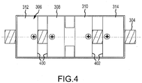
- the shimmy damper 200 further includes a plurality of magnets 306.
- the plurality of magnets 306 are designed to exert an opposing force on the cap 300 and the housing 302 via the damper shaft 304.
- the plurality of magnets 306 may include a first shaft magnet 308 and a second shaft magnet 310 each coupled to the damper shaft 304.
- the first shaft magnet 308 and the second shaft magnet 310 may be formed integral with the damper shaft 304.
- the plurality of magnets 306 may further include a cap magnet 312 and a housing magnet 314. The cap magnet 312 may be in contact with the cap 300, and the housing magnet 314 may be in contact with the housing 302.
- the cap magnet 312 may be coupled to the cap 300 and the housing magnet 314 may be coupled to the housing 302.
- the cap magnet 312 and the housing magnet 314 may be permanent magnets.
- at least one of the magnets 312, 314 may be electromagnets and, therefore, may be controlled by a controller.
- the controller may adjust the strength (i.e., the amplitude of the Mega Gauss Oersteds (MGOe)) and the polarity of the magnets 312, 314.
- the first shaft magnet 308 and the cap magnet 312 may exert an opposing force on each other, and the second shaft magnet 310 and the housing magnet 314 may likewise exert an opposing force on each other. That is, opposing faces 400 of the first shaft magnet 308 and the cap magnet 312 may have the same polarity, and opposing faces 402 of the second shaft magnet 310 and the housing magnet 314 may have the same polarity. These opposing forces may act on the cap 300 and the housing 302, urging them away from each other. This opposing force on the cap 300 and the housing 302 provides centering of the damper shaft 304, which in turn provides centering of the landing gear 102 during flight.
- a Belleville spring which may include a set of Belleville spring washers, were used to provide the centering action. Over time, the Belleville spring washers may degrade, reducing the centering action, as well as potentially resulting in fatigue failure of the Belleville spring washers. Because the plurality of magnets 306 operate without contacting parts, the shimmy damper 200 may have an extended lifetime relative to conventional shimmy dampers.
- the landing gear 102 is shown in a stowed position. As shown, the shimmy damper 200 is located between the lower torque link 206 and the upper torque link 204.
- the plurality of magnets 306 of FIG. 3 provides centering action along the Z axis (i.e., into and out of the page).
- references to "various embodiments”, “one embodiment”, “an embodiment”, “an example embodiment”, etc. indicate that the embodiment described may include a particular feature, structure, or characteristic, but every embodiment may not necessarily include the particular feature, structure, or characteristic. Moreover, such phrases are not necessarily referring to the same embodiment. Further, when a particular feature, structure, or characteristic is described in connection with an embodiment, it is submitted that it is within the knowledge of one skilled in the art to affect such feature, structure, or characteristic in connection with other embodiments whether or not explicitly described. After reading the description, it will be apparent to one skilled in the relevant art(s) how to implement the disclosure in alternative embodiments.
Landscapes
- Engineering & Computer Science (AREA)
- General Engineering & Computer Science (AREA)
- Mechanical Engineering (AREA)
- Aviation & Aerospace Engineering (AREA)
- Physics & Mathematics (AREA)
- Electromagnetism (AREA)
- Acoustics & Sound (AREA)
- Gears, Cams (AREA)
- Vibration Prevention Devices (AREA)
Abstract
Description
- The present disclosure relates to landing gear of aircraft and, more particularly, to shimmy dampers for use in landing gear of aircraft.
- Aircraft includes landing gear to support the aircraft during taxi, takeoff, and landing. The landing gear may be stowed in a bay during flight. A shimmy damper may be installed on the landing gear to provide shimmy damping during ground operations, and centering of the landing gear during flight. Without this centering, the landing gear may contact the aircraft body, potentially resulting in the landing gear failing to extend, as well as potential damage to the aircraft or landing gear.
- Disclosed herein is a shimmy damper for centering a landing gear. The shimmy damper includes a cap and a housing. The shimmy damper further includes a damper shaft extending from the cap to the housing. The shimmy damper further includes a plurality of magnets configured to exert an opposing force on the cap and the housing via the damper shaft. The damper shaft may be centered inside the housing through the magnets.
- In any of the foregoing embodiments, the plurality of magnets includes: a first shaft magnet and a second shaft magnet each coupled to the damper shaft, the first shaft magnet being located closer to the cap than the second shaft magnet; a cap magnet configured to be repelled by the first shaft magnet and to exert a force on the cap; and a housing magnet configured to be repelled by the second shaft magnet and to exert a force on the housing in an opposite direction than the force exerted on the cap by the cap magnet.
- In any of the foregoing embodiments, the cap magnet is coupled to the cap and the housing magnet is coupled to the housing.
- In any of the foregoing embodiments, the shimmy damper is configured to be coupled to a joint of the landing gear of an aircraft.
- In any of the foregoing embodiments, the joint is formed between an upper torque link and a lower torque link.
- In any of the foregoing embodiments, the damper shaft has a first end configured to be coupled to the upper torque link.
- In any of the foregoing embodiments, the damper shaft has a second end configured to be coupled to the lower torque link.
- In any of the foregoing embodiments, the plurality of magnets replaces a Belleville spring of the shimmy damper.
- Also disclosed is shimmy damper for centering a landing gear. The shimmy damper includes a cap and a housing. The shimmy damper further includes a damper shaft extending from the cap to the housing. The shimmy damper further includes a plurality of magnets configured to exert an opposing force on the cap and the housing via the damper shaft. The shimmy damper is configured to be coupled to a joint of the landing gear.
- In any of the foregoing embodiments, the plurality of magnets includes: a first shaft magnet and a second shaft magnet each coupled to the damper shaft, the first shaft magnet being located closer to the cap than the second shaft magnet; a cap magnet configured to be repelled by the first shaft magnet and to exert a force on the cap; and a housing magnet configured to be repelled by the second shaft magnet and to exert a force on the housing in an opposite direction than the force exerted on the cap by the cap magnet.
- In any of the foregoing embodiments, the cap magnet is coupled to the cap and the housing magnet is coupled to the housing.
- In any of the foregoing embodiments, the joint is formed between an upper torque link and a lower torque link.
- In any of the foregoing embodiments, the damper shaft has a first end configured to be coupled to the upper torque link.
- In any of the foregoing embodiments, the damper shaft has a second end configured to be coupled to the lower torque link.
- In any of the foregoing embodiments, the plurality of magnets replaces a Belleville spring of the shimmy damper.
- Also disclosed is a shimmy damper for centering a landing gear. The shimmy damper includes a cap and a housing. The shimmy damper further includes a damper shaft extending from the cap to the housing. The shimmy damper further includes a plurality of magnets configured to exert an opposing force on the cap and the housing via the damper shaft, the plurality of magnets including: a first shaft magnet and a second shaft magnet each coupled to the damper shaft, the first shaft magnet being located closer to the cap than the second shaft magnet, a cap magnet configured to be repelled by the first shaft magnet and to exert a force on the cap, and a housing magnet configured to be repelled by the second shaft magnet and to exert a force on the housing in an opposite direction than the force exerted on the cap by the cap magnet.
- In any of the foregoing embodiments, the cap magnet is coupled to the cap and the housing magnet is coupled to the housing.
- In any of the foregoing embodiments, the shimmy damper is configured to be coupled to a joint of the landing gear of an aircraft.
- In any of the foregoing embodiments, the joint is formed between an upper torque link and a lower torque link.
- In any of the foregoing embodiments, the damper shaft has a first end configured to be coupled to the upper torque link and a second end configured to be coupled to the lower torque link.
- The foregoing features and elements may be combined in various combinations without exclusivity, unless expressly indicated otherwise. These features and elements as well as the operation thereof will become more apparent in light of the following description and the accompanying drawings. It should be understood, however, the following description and drawings are intended to be exemplary in nature and non-limiting.
- The subject matter of the present disclosure is particularly pointed out and distinctly claimed in the concluding portion of the specification. A more complete understanding of the present disclosure, however, may best be obtained by referring to the detailed description and claims when considered in connection with the figures, wherein like numerals denote like elements.
-
FIG. 1 illustrates an aircraft with a landing gear, in accordance with various embodiments; -
FIG. 2 illustrates details of the landing gear ofFIG. 1 , in accordance with various embodiments; -
FIG. 3 illustrates a shimmy damper of the landing gear ofFIG. 2 , in accordance with various embodiments; -
FIG. 4 illustrates a plurality of magnets of the shimmy damper ofFIG. 3 , according to various embodiments; and -
FIG. 5 illustrates the landing gear ofFIG. 1 in a stowed position, according to various embodiments. - The detailed description of exemplary embodiments herein makes reference to the accompanying drawings, which show exemplary embodiments by way of illustration. While these exemplary embodiments are described in sufficient detail to enable those skilled in the art to practice the exemplary embodiments of the disclosure, it should be understood that other embodiments may be realized and that logical changes and adaptations in design and construction may be made in accordance with this disclosure and the teachings herein. Thus, the detailed description herein is presented for purposes of illustration only and not limitation. The steps recited in any of the method or process descriptions may be executed in any order and are not necessarily limited to the order presented.
- Furthermore, any reference to singular includes plural embodiments, and any reference to more than one component or step may include a singular embodiment or step. Also, any reference to attached, fixed, connected or the like may include permanent, removable, temporary, partial, full and/or any other possible attachment option. Additionally, any reference to without contact (or similar phrases) may also include reduced contact or minimal contact. Surface shading lines may be used throughout the figures to denote different parts but not necessarily to denote the same or different materials.
- Referring now to
FIG. 1 , anaircraft 100 may include one ormore landing gear 102 which may be deployed during taxi, takeoff, and landing, and may be stowed in abay 104 during flight. An X-Y-Z axis is shown throughout the drawings to illustrate the relative location of components. - Referring now to
FIG. 2 , additional details of thelanding gear 102 are shown. Thelanding gear 102 may have a top 210 designed to be coupled to an aircraft and abottom 208 on which one or more wheel assembly is installed. In various embodiments, thetop 210 may be coupled to, or include, a retract actuator or another component. In that regard, the top 210 may be directly or indirectly coupled to the aircraft. - The
landing gear 102 may include ashimmy damper 200. Theshimmy damper 200 may provide for centering of thelanding gear 102 in response to thelanding gear 102 being stowed. Theshimmy damper 200 may be installed at a joint 202 of thelanding gear 102. In particular, theshimmy damper 200 may be installed between alower torque link 206 and anupper torque link 204. In various embodiments, theshimmy damper 200 may also provide some damping of thelanding gear 102. - Turning now to
FIG. 3 , a cross-sectional view of theshimmy damper 200 is shown. The features of theshimmy damper 200 are enclosed within ahousing 302 and acap 300. Theshimmy damper 200 includes adamper shaft 304 extending therethrough. Thedamper shaft 304 may be used in conjunction with hydraulics to provide hydraulic damping of thelanding gear 102 ofFIG. 1 during ground operations. - The
shimmy damper 200 further includes a plurality ofmagnets 306. The plurality ofmagnets 306 are designed to exert an opposing force on thecap 300 and thehousing 302 via thedamper shaft 304. In particular and referring toFIGS. 3 and4 , the plurality ofmagnets 306 may include afirst shaft magnet 308 and asecond shaft magnet 310 each coupled to thedamper shaft 304. In various embodiments, thefirst shaft magnet 308 and thesecond shaft magnet 310 may be formed integral with thedamper shaft 304. The plurality ofmagnets 306 may further include acap magnet 312 and ahousing magnet 314. Thecap magnet 312 may be in contact with thecap 300, and thehousing magnet 314 may be in contact with thehousing 302. In various embodiments, thecap magnet 312 may be coupled to thecap 300 and thehousing magnet 314 may be coupled to thehousing 302. Thecap magnet 312 and thehousing magnet 314 may be permanent magnets. In various embodiments, at least one of themagnets magnets - The
first shaft magnet 308 and thecap magnet 312 may exert an opposing force on each other, and thesecond shaft magnet 310 and thehousing magnet 314 may likewise exert an opposing force on each other. That is, opposing faces 400 of thefirst shaft magnet 308 and thecap magnet 312 may have the same polarity, and opposingfaces 402 of thesecond shaft magnet 310 and thehousing magnet 314 may have the same polarity. These opposing forces may act on thecap 300 and thehousing 302, urging them away from each other. This opposing force on thecap 300 and thehousing 302 provides centering of thedamper shaft 304, which in turn provides centering of thelanding gear 102 during flight. - Use of the plurality of
magnets 306 provides various advantages. For example, a Belleville spring, which may include a set of Belleville spring washers, were used to provide the centering action. Over time, the Belleville spring washers may degrade, reducing the centering action, as well as potentially resulting in fatigue failure of the Belleville spring washers. Because the plurality ofmagnets 306 operate without contacting parts, theshimmy damper 200 may have an extended lifetime relative to conventional shimmy dampers. - Referring now to
FIG. 5 , thelanding gear 102 is shown in a stowed position. As shown, theshimmy damper 200 is located between thelower torque link 206 and theupper torque link 204. The plurality ofmagnets 306 ofFIG. 3 provides centering action along the Z axis (i.e., into and out of the page). - Benefits and other advantages have been described herein with regard to specific embodiments. Furthermore, the connecting lines shown in the various figures contained herein are intended to represent exemplary functional relationships and/or physical couplings between the various elements. It should be noted that many alternative or additional functional relationships or physical connections may be present in a practical system. However, the benefits, advantages, and any elements that may cause any benefit or advantage to occur or become more pronounced are not to be construed as critical, required, or essential features or elements of the disclosure. The scope of the disclosure is accordingly to be limited by nothing other than the appended claims, in which reference to an element in the singular is not intended to mean "one and only one" unless explicitly so stated, but rather "one or more." Moreover, where a phrase similar to "at least one of A, B, or C" is used in the claims, it is intended that the phrase be interpreted to mean that A alone may be present in an embodiment, B alone may be present in an embodiment, C alone may be present in an embodiment, or that any combination of the elements A, B and C may be present in a single embodiment; for example, A and B, A and C, B and C, or A and B and C.
- Systems, methods and apparatus are provided herein. In the detailed description herein, references to "various embodiments", "one embodiment", "an embodiment", "an example embodiment", etc., indicate that the embodiment described may include a particular feature, structure, or characteristic, but every embodiment may not necessarily include the particular feature, structure, or characteristic. Moreover, such phrases are not necessarily referring to the same embodiment. Further, when a particular feature, structure, or characteristic is described in connection with an embodiment, it is submitted that it is within the knowledge of one skilled in the art to affect such feature, structure, or characteristic in connection with other embodiments whether or not explicitly described. After reading the description, it will be apparent to one skilled in the relevant art(s) how to implement the disclosure in alternative embodiments.
Claims (8)
- A shimmy damper for centering a landing gear, the shimmy damper comprising:a cap (300);a housing (302);a damper shaft (304) extending from the cap to the housing; anda plurality of magnets (306) configured to exert an opposing force on the cap and the housing via the damper shaft.
- The shimmy damper of claim 1, wherein the plurality of magnets includes:a first shaft magnet (308) and a second shaft magnet (310) each coupled to the damper shaft, the first shaft magnet being located closer to the cap than the second shaft magnet;a cap magnet (312) configured to be repelled by the first shaft magnet and to exert a force on the cap; anda housing magnet (314) configured to be repelled by the second shaft magnet and to exert a force on the housing in an opposite direction than the force exerted on the cap by the cap magnet.
- The shimmy damper of claim 2, wherein the cap magnet (312) is coupled to the cap and the housing magnet (314) is coupled to the housing.
- The shimmy damper of any preceding claim, wherein the shimmy damper is configured to be coupled to a joint (202) of the landing gear (102) of an aircraft.
- The shimmy damper of claim 4, wherein the joint is formed between an upper torque link (204) and a lower torque link (206).
- The shimmy damper of claim 5, wherein the damper shaft has a first end configured to be coupled to the upper torque link (204).
- The shimmy damper of claim 6, wherein the damper shaft has a second end configured to be coupled to the lower torque link (206).
- The shimmy damper of any preceding claim, wherein the plurality of magnets replaces a Belleville spring of the shimmy damper.
Applications Claiming Priority (1)
| Application Number | Priority Date | Filing Date | Title |
|---|---|---|---|
| US16/823,817 US11492104B2 (en) | 2020-03-19 | 2020-03-19 | Magnetic self-centering shimmy damper |
Publications (2)
| Publication Number | Publication Date |
|---|---|
| EP3882137A1 true EP3882137A1 (en) | 2021-09-22 |
| EP3882137B1 EP3882137B1 (en) | 2024-08-14 |
Family
ID=75111497
Family Applications (1)
| Application Number | Title | Priority Date | Filing Date |
|---|---|---|---|
| EP21163709.5A Active EP3882137B1 (en) | 2020-03-19 | 2021-03-19 | Magnetic self-centering shimmy damper |
Country Status (3)
| Country | Link |
|---|---|
| US (1) | US11492104B2 (en) |
| EP (1) | EP3882137B1 (en) |
| CA (1) | CA3112551A1 (en) |
Cited By (2)
| Publication number | Priority date | Publication date | Assignee | Title |
|---|---|---|---|---|
| EP4198334A1 (en) * | 2021-12-14 | 2023-06-21 | Goodrich Corporation | Self-sustaining shimmy damper system for landing gear shock strut assemblies |
| US12384530B2 (en) | 2021-12-14 | 2025-08-12 | Goodrich Corporation | Self-sustaining shimmy damper system for landing gear shock strut assemblies |
Families Citing this family (1)
| Publication number | Priority date | Publication date | Assignee | Title |
|---|---|---|---|---|
| CN114354160B (en) * | 2021-12-28 | 2024-02-23 | 保定向阳航空精密机械有限公司 | Damping characteristic testing device of shimmy damper |
Citations (6)
| Publication number | Priority date | Publication date | Assignee | Title |
|---|---|---|---|---|
| US4432441A (en) * | 1981-04-13 | 1984-02-21 | Kokka Kogyo Kabushiki Kaisha | Vibration isolation apparatus |
| EP2778047A2 (en) * | 2013-03-15 | 2014-09-17 | Goodrich Actuation Systems Ltd. | Damping arrangement for aircraft landing gear, for example a nosewheel |
| EP3118479A1 (en) * | 2015-07-15 | 2017-01-18 | Messier-Dowty Ltd | Shock absorber |
| US20170102047A1 (en) * | 2015-10-13 | 2017-04-13 | Goodrich Corporation | Saturation-controlled variable damper systems and methods |
| CN107021212A (en) * | 2017-03-03 | 2017-08-08 | 中国民航大学 | A kind of plate turning type magnetorheological shimmy damper for undercarriage |
| US20180086440A1 (en) * | 2016-09-29 | 2018-03-29 | Safran Landing Systems | Aircraft undercarriage fitted with a shimmy-attenuator device |
Family Cites Families (5)
| Publication number | Priority date | Publication date | Assignee | Title |
|---|---|---|---|---|
| GB201209527D0 (en) | 2012-05-29 | 2012-07-11 | Airbus Operations Ltd | Aircraft landing gear arrangement, a kit therefore, an aircraft comprising the same and a method of determining the angular position of an aircraft wheel |
| EP3078877B1 (en) | 2015-04-10 | 2017-12-27 | Safran Landing Systems UK Limited | Hydraulic shock absorber |
| GB2538746A (en) | 2015-05-27 | 2016-11-30 | Airbus Operations Ltd | An actuator |
| CN107191530B (en) * | 2017-05-26 | 2019-02-01 | 中国民航大学 | A kind of twin coil piston magneto-rheological liquid shimmy-damper |
| DE102017116228A1 (en) * | 2017-07-19 | 2019-01-24 | Thyssenkrupp Ag | Shock absorbers, in particular gas pressure shock absorbers for a vehicle, and suspension and vehicle with such a shock absorber |
-
2020
- 2020-03-19 US US16/823,817 patent/US11492104B2/en active Active
-
2021
- 2021-03-17 CA CA3112551A patent/CA3112551A1/en active Pending
- 2021-03-19 EP EP21163709.5A patent/EP3882137B1/en active Active
Patent Citations (6)
| Publication number | Priority date | Publication date | Assignee | Title |
|---|---|---|---|---|
| US4432441A (en) * | 1981-04-13 | 1984-02-21 | Kokka Kogyo Kabushiki Kaisha | Vibration isolation apparatus |
| EP2778047A2 (en) * | 2013-03-15 | 2014-09-17 | Goodrich Actuation Systems Ltd. | Damping arrangement for aircraft landing gear, for example a nosewheel |
| EP3118479A1 (en) * | 2015-07-15 | 2017-01-18 | Messier-Dowty Ltd | Shock absorber |
| US20170102047A1 (en) * | 2015-10-13 | 2017-04-13 | Goodrich Corporation | Saturation-controlled variable damper systems and methods |
| US20180086440A1 (en) * | 2016-09-29 | 2018-03-29 | Safran Landing Systems | Aircraft undercarriage fitted with a shimmy-attenuator device |
| CN107021212A (en) * | 2017-03-03 | 2017-08-08 | 中国民航大学 | A kind of plate turning type magnetorheological shimmy damper for undercarriage |
Cited By (2)
| Publication number | Priority date | Publication date | Assignee | Title |
|---|---|---|---|---|
| EP4198334A1 (en) * | 2021-12-14 | 2023-06-21 | Goodrich Corporation | Self-sustaining shimmy damper system for landing gear shock strut assemblies |
| US12384530B2 (en) | 2021-12-14 | 2025-08-12 | Goodrich Corporation | Self-sustaining shimmy damper system for landing gear shock strut assemblies |
Also Published As
| Publication number | Publication date |
|---|---|
| BR102021005059A2 (en) | 2021-09-28 |
| US11492104B2 (en) | 2022-11-08 |
| CA3112551A1 (en) | 2021-09-19 |
| US20210291967A1 (en) | 2021-09-23 |
| EP3882137B1 (en) | 2024-08-14 |
Similar Documents
| Publication | Publication Date | Title |
|---|---|---|
| EP3882137B1 (en) | Magnetic self-centering shimmy damper | |
| US11548129B2 (en) | Method and assembly for extracting press fit bushings | |
| EP3712060A1 (en) | Non-jamming shrink latch assembly for retractable aircraft landing gear | |
| CN104648658A (en) | Drive assembly with selective disconnect | |
| US10974819B2 (en) | Latch assembly for shock strut | |
| US10479485B2 (en) | Aircraft landing gear assembly | |
| US10486799B2 (en) | Rod end | |
| EP3495686B1 (en) | Systems and methods for dampening dynamic loading | |
| US10626917B1 (en) | Hybrid metallic/composite joint with separate internal bearing | |
| EP3744631B1 (en) | Shock strut shrinking system | |
| CN104309821A (en) | Repeatable maglev flywheel locking device | |
| US2367033A (en) | Actuator mounting | |
| US12384530B2 (en) | Self-sustaining shimmy damper system for landing gear shock strut assemblies | |
| EP3539868A1 (en) | Flexible coupling for standpipe assembly | |
| EP3090943A1 (en) | Landing gear including a bogie beam assembly and method for coupling an axle to a bogie beam thereof | |
| CN109835479A (en) | Paddle shaft and the integrated tail-rotor axis of propeller hub | |
| EP3722627B1 (en) | Hybrid metallic/composite joint with integral bearing | |
| US10829207B2 (en) | Non-jamming shrink latch mechanism | |
| US20170001701A1 (en) | System for Embedded Removable Aperture | |
| EP4198334A1 (en) | Self-sustaining shimmy damper system for landing gear shock strut assemblies | |
| US9821904B2 (en) | Landing gear with structural load path diverter bracket | |
| US9511876B2 (en) | Actuator housing for ram air turbine deployment actuator | |
| EP3722621B1 (en) | Hybrid metallic/composite joint with separate internal bearing and coupling flange | |
| EP4234399A1 (en) | Integral steering motor and collar for landing gear | |
| EP4040010A1 (en) | Shock strut assemblies for landing gear |
Legal Events
| Date | Code | Title | Description |
|---|---|---|---|
| PUAI | Public reference made under article 153(3) epc to a published international application that has entered the european phase |
Free format text: ORIGINAL CODE: 0009012 |
|
| STAA | Information on the status of an ep patent application or granted ep patent |
Free format text: STATUS: THE APPLICATION HAS BEEN PUBLISHED |
|
| AK | Designated contracting states |
Kind code of ref document: A1 Designated state(s): AL AT BE BG CH CY CZ DE DK EE ES FI FR GB GR HR HU IE IS IT LI LT LU LV MC MK MT NL NO PL PT RO RS SE SI SK SM TR |
|
| STAA | Information on the status of an ep patent application or granted ep patent |
Free format text: STATUS: REQUEST FOR EXAMINATION WAS MADE |
|
| 17P | Request for examination filed |
Effective date: 20220322 |
|
| RBV | Designated contracting states (corrected) |
Designated state(s): AL AT BE BG CH CY CZ DE DK EE ES FI FR GB GR HR HU IE IS IT LI LT LU LV MC MK MT NL NO PL PT RO RS SE SI SK SM TR |
|
| STAA | Information on the status of an ep patent application or granted ep patent |
Free format text: STATUS: EXAMINATION IS IN PROGRESS |
|
| 17Q | First examination report despatched |
Effective date: 20230215 |
|
| P01 | Opt-out of the competence of the unified patent court (upc) registered |
Effective date: 20230922 |
|
| GRAP | Despatch of communication of intention to grant a patent |
Free format text: ORIGINAL CODE: EPIDOSNIGR1 |
|
| STAA | Information on the status of an ep patent application or granted ep patent |
Free format text: STATUS: GRANT OF PATENT IS INTENDED |
|
| INTG | Intention to grant announced |
Effective date: 20240312 |
|
| GRAS | Grant fee paid |
Free format text: ORIGINAL CODE: EPIDOSNIGR3 |
|
| GRAA | (expected) grant |
Free format text: ORIGINAL CODE: 0009210 |
|
| STAA | Information on the status of an ep patent application or granted ep patent |
Free format text: STATUS: THE PATENT HAS BEEN GRANTED |
|
| AK | Designated contracting states |
Kind code of ref document: B1 Designated state(s): AL AT BE BG CH CY CZ DE DK EE ES FI FR GB GR HR HU IE IS IT LI LT LU LV MC MK MT NL NO PL PT RO RS SE SI SK SM TR |
|
| REG | Reference to a national code |
Ref country code: GB Ref legal event code: FG4D |
|
| REG | Reference to a national code |
Ref country code: CH Ref legal event code: EP |
|
| REG | Reference to a national code |
Ref country code: DE Ref legal event code: R096 Ref document number: 602021017061 Country of ref document: DE |
|
| REG | Reference to a national code |
Ref country code: IE Ref legal event code: FG4D |
|
| REG | Reference to a national code |
Ref country code: LT Ref legal event code: MG9D |
|
| REG | Reference to a national code |
Ref country code: NL Ref legal event code: MP Effective date: 20240814 |
|
| PG25 | Lapsed in a contracting state [announced via postgrant information from national office to epo] |
Ref country code: NO Free format text: LAPSE BECAUSE OF FAILURE TO SUBMIT A TRANSLATION OF THE DESCRIPTION OR TO PAY THE FEE WITHIN THE PRESCRIBED TIME-LIMIT Effective date: 20241114 |
|
| REG | Reference to a national code |
Ref country code: AT Ref legal event code: MK05 Ref document number: 1713091 Country of ref document: AT Kind code of ref document: T Effective date: 20240814 |
|
| PG25 | Lapsed in a contracting state [announced via postgrant information from national office to epo] |
Ref country code: NL Free format text: LAPSE BECAUSE OF FAILURE TO SUBMIT A TRANSLATION OF THE DESCRIPTION OR TO PAY THE FEE WITHIN THE PRESCRIBED TIME-LIMIT Effective date: 20240814 Ref country code: GR Free format text: LAPSE BECAUSE OF FAILURE TO SUBMIT A TRANSLATION OF THE DESCRIPTION OR TO PAY THE FEE WITHIN THE PRESCRIBED TIME-LIMIT Effective date: 20241115 Ref country code: PL Free format text: LAPSE BECAUSE OF FAILURE TO SUBMIT A TRANSLATION OF THE DESCRIPTION OR TO PAY THE FEE WITHIN THE PRESCRIBED TIME-LIMIT Effective date: 20240814 Ref country code: FI Free format text: LAPSE BECAUSE OF FAILURE TO SUBMIT A TRANSLATION OF THE DESCRIPTION OR TO PAY THE FEE WITHIN THE PRESCRIBED TIME-LIMIT Effective date: 20240814 Ref country code: PT Free format text: LAPSE BECAUSE OF FAILURE TO SUBMIT A TRANSLATION OF THE DESCRIPTION OR TO PAY THE FEE WITHIN THE PRESCRIBED TIME-LIMIT Effective date: 20241216 |
|
| PG25 | Lapsed in a contracting state [announced via postgrant information from national office to epo] |
Ref country code: BG Free format text: LAPSE BECAUSE OF FAILURE TO SUBMIT A TRANSLATION OF THE DESCRIPTION OR TO PAY THE FEE WITHIN THE PRESCRIBED TIME-LIMIT Effective date: 20240814 |
|
| PG25 | Lapsed in a contracting state [announced via postgrant information from national office to epo] |
Ref country code: LV Free format text: LAPSE BECAUSE OF FAILURE TO SUBMIT A TRANSLATION OF THE DESCRIPTION OR TO PAY THE FEE WITHIN THE PRESCRIBED TIME-LIMIT Effective date: 20240814 |
|
| PG25 | Lapsed in a contracting state [announced via postgrant information from national office to epo] |
Ref country code: IS Free format text: LAPSE BECAUSE OF FAILURE TO SUBMIT A TRANSLATION OF THE DESCRIPTION OR TO PAY THE FEE WITHIN THE PRESCRIBED TIME-LIMIT Effective date: 20241214 Ref country code: AT Free format text: LAPSE BECAUSE OF FAILURE TO SUBMIT A TRANSLATION OF THE DESCRIPTION OR TO PAY THE FEE WITHIN THE PRESCRIBED TIME-LIMIT Effective date: 20240814 |
|
| PG25 | Lapsed in a contracting state [announced via postgrant information from national office to epo] |
Ref country code: HR Free format text: LAPSE BECAUSE OF FAILURE TO SUBMIT A TRANSLATION OF THE DESCRIPTION OR TO PAY THE FEE WITHIN THE PRESCRIBED TIME-LIMIT Effective date: 20240814 |
|
| PG25 | Lapsed in a contracting state [announced via postgrant information from national office to epo] |
Ref country code: RS Free format text: LAPSE BECAUSE OF FAILURE TO SUBMIT A TRANSLATION OF THE DESCRIPTION OR TO PAY THE FEE WITHIN THE PRESCRIBED TIME-LIMIT Effective date: 20241114 Ref country code: ES Free format text: LAPSE BECAUSE OF FAILURE TO SUBMIT A TRANSLATION OF THE DESCRIPTION OR TO PAY THE FEE WITHIN THE PRESCRIBED TIME-LIMIT Effective date: 20240814 |
|
| PG25 | Lapsed in a contracting state [announced via postgrant information from national office to epo] |
Ref country code: RS Free format text: LAPSE BECAUSE OF FAILURE TO SUBMIT A TRANSLATION OF THE DESCRIPTION OR TO PAY THE FEE WITHIN THE PRESCRIBED TIME-LIMIT Effective date: 20241114 Ref country code: PT Free format text: LAPSE BECAUSE OF FAILURE TO SUBMIT A TRANSLATION OF THE DESCRIPTION OR TO PAY THE FEE WITHIN THE PRESCRIBED TIME-LIMIT Effective date: 20241216 Ref country code: PL Free format text: LAPSE BECAUSE OF FAILURE TO SUBMIT A TRANSLATION OF THE DESCRIPTION OR TO PAY THE FEE WITHIN THE PRESCRIBED TIME-LIMIT Effective date: 20240814 Ref country code: NO Free format text: LAPSE BECAUSE OF FAILURE TO SUBMIT A TRANSLATION OF THE DESCRIPTION OR TO PAY THE FEE WITHIN THE PRESCRIBED TIME-LIMIT Effective date: 20241114 Ref country code: NL Free format text: LAPSE BECAUSE OF FAILURE TO SUBMIT A TRANSLATION OF THE DESCRIPTION OR TO PAY THE FEE WITHIN THE PRESCRIBED TIME-LIMIT Effective date: 20240814 Ref country code: LV Free format text: LAPSE BECAUSE OF FAILURE TO SUBMIT A TRANSLATION OF THE DESCRIPTION OR TO PAY THE FEE WITHIN THE PRESCRIBED TIME-LIMIT Effective date: 20240814 Ref country code: IS Free format text: LAPSE BECAUSE OF FAILURE TO SUBMIT A TRANSLATION OF THE DESCRIPTION OR TO PAY THE FEE WITHIN THE PRESCRIBED TIME-LIMIT Effective date: 20241214 Ref country code: HR Free format text: LAPSE BECAUSE OF FAILURE TO SUBMIT A TRANSLATION OF THE DESCRIPTION OR TO PAY THE FEE WITHIN THE PRESCRIBED TIME-LIMIT Effective date: 20240814 Ref country code: GR Free format text: LAPSE BECAUSE OF FAILURE TO SUBMIT A TRANSLATION OF THE DESCRIPTION OR TO PAY THE FEE WITHIN THE PRESCRIBED TIME-LIMIT Effective date: 20241115 Ref country code: FI Free format text: LAPSE BECAUSE OF FAILURE TO SUBMIT A TRANSLATION OF THE DESCRIPTION OR TO PAY THE FEE WITHIN THE PRESCRIBED TIME-LIMIT Effective date: 20240814 Ref country code: ES Free format text: LAPSE BECAUSE OF FAILURE TO SUBMIT A TRANSLATION OF THE DESCRIPTION OR TO PAY THE FEE WITHIN THE PRESCRIBED TIME-LIMIT Effective date: 20240814 Ref country code: BG Free format text: LAPSE BECAUSE OF FAILURE TO SUBMIT A TRANSLATION OF THE DESCRIPTION OR TO PAY THE FEE WITHIN THE PRESCRIBED TIME-LIMIT Effective date: 20240814 Ref country code: AT Free format text: LAPSE BECAUSE OF FAILURE TO SUBMIT A TRANSLATION OF THE DESCRIPTION OR TO PAY THE FEE WITHIN THE PRESCRIBED TIME-LIMIT Effective date: 20240814 |
|
| PG25 | Lapsed in a contracting state [announced via postgrant information from national office to epo] |
Ref country code: DK Free format text: LAPSE BECAUSE OF FAILURE TO SUBMIT A TRANSLATION OF THE DESCRIPTION OR TO PAY THE FEE WITHIN THE PRESCRIBED TIME-LIMIT Effective date: 20240814 Ref country code: RO Free format text: LAPSE BECAUSE OF FAILURE TO SUBMIT A TRANSLATION OF THE DESCRIPTION OR TO PAY THE FEE WITHIN THE PRESCRIBED TIME-LIMIT Effective date: 20240814 Ref country code: SM Free format text: LAPSE BECAUSE OF FAILURE TO SUBMIT A TRANSLATION OF THE DESCRIPTION OR TO PAY THE FEE WITHIN THE PRESCRIBED TIME-LIMIT Effective date: 20240814 |
|
| PG25 | Lapsed in a contracting state [announced via postgrant information from national office to epo] |
Ref country code: EE Free format text: LAPSE BECAUSE OF FAILURE TO SUBMIT A TRANSLATION OF THE DESCRIPTION OR TO PAY THE FEE WITHIN THE PRESCRIBED TIME-LIMIT Effective date: 20240814 |
|
| PG25 | Lapsed in a contracting state [announced via postgrant information from national office to epo] |
Ref country code: CZ Free format text: LAPSE BECAUSE OF FAILURE TO SUBMIT A TRANSLATION OF THE DESCRIPTION OR TO PAY THE FEE WITHIN THE PRESCRIBED TIME-LIMIT Effective date: 20240814 |
|
| PG25 | Lapsed in a contracting state [announced via postgrant information from national office to epo] |
Ref country code: SK Free format text: LAPSE BECAUSE OF FAILURE TO SUBMIT A TRANSLATION OF THE DESCRIPTION OR TO PAY THE FEE WITHIN THE PRESCRIBED TIME-LIMIT Effective date: 20240814 Ref country code: IT Free format text: LAPSE BECAUSE OF FAILURE TO SUBMIT A TRANSLATION OF THE DESCRIPTION OR TO PAY THE FEE WITHIN THE PRESCRIBED TIME-LIMIT Effective date: 20240814 |
|
| REG | Reference to a national code |
Ref country code: DE Ref legal event code: R097 Ref document number: 602021017061 Country of ref document: DE |
|
| PLBE | No opposition filed within time limit |
Free format text: ORIGINAL CODE: 0009261 |
|
| STAA | Information on the status of an ep patent application or granted ep patent |
Free format text: STATUS: NO OPPOSITION FILED WITHIN TIME LIMIT |
|
| 26N | No opposition filed |
Effective date: 20250515 |
|
| PG25 | Lapsed in a contracting state [announced via postgrant information from national office to epo] |
Ref country code: SE Free format text: LAPSE BECAUSE OF FAILURE TO SUBMIT A TRANSLATION OF THE DESCRIPTION OR TO PAY THE FEE WITHIN THE PRESCRIBED TIME-LIMIT Effective date: 20240814 |
|
| PG25 | Lapsed in a contracting state [announced via postgrant information from national office to epo] |
Ref country code: MC Free format text: LAPSE BECAUSE OF FAILURE TO SUBMIT A TRANSLATION OF THE DESCRIPTION OR TO PAY THE FEE WITHIN THE PRESCRIBED TIME-LIMIT Effective date: 20240814 |
|
| REG | Reference to a national code |
Ref country code: CH Ref legal event code: H13 Free format text: ST27 STATUS EVENT CODE: U-0-0-H10-H13 (AS PROVIDED BY THE NATIONAL OFFICE) Effective date: 20251023 |
|
| PG25 | Lapsed in a contracting state [announced via postgrant information from national office to epo] |
Ref country code: LU Free format text: LAPSE BECAUSE OF NON-PAYMENT OF DUE FEES Effective date: 20250319 |
|
| REG | Reference to a national code |
Ref country code: BE Ref legal event code: MM Effective date: 20250331 |
|
| PG25 | Lapsed in a contracting state [announced via postgrant information from national office to epo] |
Ref country code: BE Free format text: LAPSE BECAUSE OF NON-PAYMENT OF DUE FEES Effective date: 20250331 |
|
| PG25 | Lapsed in a contracting state [announced via postgrant information from national office to epo] |
Ref country code: CH Free format text: LAPSE BECAUSE OF NON-PAYMENT OF DUE FEES Effective date: 20250331 |
|
| PG25 | Lapsed in a contracting state [announced via postgrant information from national office to epo] |
Ref country code: IE Free format text: LAPSE BECAUSE OF NON-PAYMENT OF DUE FEES Effective date: 20250319 |
|
| PGFP | Annual fee paid to national office [announced via postgrant information from national office to epo] |
Ref country code: GB Payment date: 20260220 Year of fee payment: 6 |
|
| PGFP | Annual fee paid to national office [announced via postgrant information from national office to epo] |
Ref country code: DE Payment date: 20260219 Year of fee payment: 6 |
|
| PGFP | Annual fee paid to national office [announced via postgrant information from national office to epo] |
Ref country code: FR Payment date: 20260219 Year of fee payment: 6 |