EP3882086A1 - Sensorized panel for detection of an impact on a vehicle - Google Patents
Sensorized panel for detection of an impact on a vehicle Download PDFInfo
- Publication number
- EP3882086A1 EP3882086A1 EP21163546.1A EP21163546A EP3882086A1 EP 3882086 A1 EP3882086 A1 EP 3882086A1 EP 21163546 A EP21163546 A EP 21163546A EP 3882086 A1 EP3882086 A1 EP 3882086A1
- Authority
- EP
- European Patent Office
- Prior art keywords
- panel
- filament
- vehicle
- panel according
- respect
- Prior art date
- Legal status (The legal status is an assumption and is not a legal conclusion. Google has not performed a legal analysis and makes no representation as to the accuracy of the status listed.)
- Granted
Links
Images


Classifications
-
- B—PERFORMING OPERATIONS; TRANSPORTING
- B60—VEHICLES IN GENERAL
- B60R—VEHICLES, VEHICLE FITTINGS, OR VEHICLE PARTS, NOT OTHERWISE PROVIDED FOR
- B60R16/00—Electric or fluid circuits specially adapted for vehicles and not otherwise provided for; Arrangement of elements of electric or fluid circuits specially adapted for vehicles and not otherwise provided for
- B60R16/02—Electric or fluid circuits specially adapted for vehicles and not otherwise provided for; Arrangement of elements of electric or fluid circuits specially adapted for vehicles and not otherwise provided for electric constitutive elements
- B60R16/023—Electric or fluid circuits specially adapted for vehicles and not otherwise provided for; Arrangement of elements of electric or fluid circuits specially adapted for vehicles and not otherwise provided for electric constitutive elements for transmission of signals between vehicle parts or subsystems
- B60R16/0231—Circuits relating to the driving or the functioning of the vehicle
- B60R16/0232—Circuits relating to the driving or the functioning of the vehicle for measuring vehicle parameters and indicating critical, abnormal or dangerous conditions
- B60R16/0234—Circuits relating to the driving or the functioning of the vehicle for measuring vehicle parameters and indicating critical, abnormal or dangerous conditions related to maintenance or repairing of vehicles
Definitions
- the present invention relates to a vehicle panel, such as for example a vehicle body panel, in particular of a hybrid, electric or alternative-powered vehicle such as a gas- or hydrogen-powered vehicle or in general any other vehicle requiring the interruption of an electric circuit following its mechanical breakage.
- a vehicle panel such as for example a vehicle body panel, in particular of a hybrid, electric or alternative-powered vehicle such as a gas- or hydrogen-powered vehicle or in general any other vehicle requiring the interruption of an electric circuit following its mechanical breakage.
- Vehicles in particular electric or hybrid vehicles, comprise functional elements such as parts of electrical equipment, for example, high voltage cables or batteries used to provide adequate energy to electric motors that allow the vehicle to be driven.
- An example of such electrical parts of use may be represented by the so-called HVIL (High Voltage Interlock) or interlock circuit.
- protection systems configured to insulate the above-mentioned functional elements, i.e., for example, to insulate the circuits connected to the above-mentioned electrical equipment parts, such as the HVIL circuit, so as to prevent possible electric shock to users.
- An example of such a protection system is an opening signal generated by the impact signal which allows the operation of the air-bag system.
- this signal may be incorrectly generated or may not be generated at all due to a low-impulse impact which, however, is capable of causing significant damage to the vehicle.
- the object of the present invention is to meet the above requirements in an optimized and cost-effective manner.
- the reference number 1 indicates a vehicle as a whole, in the non-limiting example illustrated herein a Light Commercial Vehicle, LCV, comprising, as is known, a frame (not shown for simplicity) and a plurality of panels 2 defining the body of the said vehicle 1.
- LCV Light Commercial Vehicle
- the vehicle 1 also comprises at least one air-bag system 3 of a known type and configured to expand and cushion impacts that may potentially cause damage to the driver or passenger.
- the vehicle 1 further comprises an electronic unit 4 configured to control a plurality of vehicle systems, including the above-mentioned air-bag system 3 and functional elements, not shown and configured to allow the operation of the vehicle, such as high voltage electrical equipment parts or control valves connected to the alternative fuel supply and distribution systems on board the vehicle.
- an electronic unit 4 configured to control a plurality of vehicle systems, including the above-mentioned air-bag system 3 and functional elements, not shown and configured to allow the operation of the vehicle, such as high voltage electrical equipment parts or control valves connected to the alternative fuel supply and distribution systems on board the vehicle.
- Figure 2 shows a panel 2 according to a first embodiment of the invention comprising a body defining any substantially flat shape, i.e., with two dimensions much larger than the thickness of the said body.
- a parallelepiped portion is shown, for example, a body portion made of any shape and material, for example plastic.
- the panel 2 comprises a filament 5 made of electrically conductive material carried by the panel 2 and configured to break in case of impact and fracture of the panel 2.
- the filament 5 made of electrically conductive material is incorporated inside the body of the panel 2 so that it is not exposed to atmospheric agents and possible mechanical wear or abrasion. Even more advantageously, it is embedded in a plane corresponding to a neutral centre plane of the panel 2.
- Neutral plane refers to the plane in which the bending stresses on the panel 2 are the lowest (theoretically zero) with respect to a bending load imparted thereon.
- the filament 5 made of electrically conductive material enters through a first opening 6 inside the body of the panel 2 and exits therefrom through an opening 7 formed therein.
- the filament 5 made of electrically conductive material defines a path along the panel 2 so that it extends by at least twice the largest dimension of the panel 2.
- the filament 5 made of electrically conductive material defines a path extending far beyond twice the largest dimension of the panel 2, thereby providing a complex path to cover most of the surface defined by the panel 2.
- the filament 5 made of electrically conductive material defines a plurality of coils 5a parallel to the larger side of the panel 2.
- the plurality of coils 5a is embedded within the panel 2 between the first opening 6 and the second opening 7, which are positioned one below the other, respectively, and formed on the smaller edge of the panel 2.
- the path of the filament 5 made of electrically conductive material inside the panel 2 defines a "fork" shape due to the plurality of coils 5a connected, at one end and at the other, to the openings 6 and 7.
- connection means 8 here shown as holes 9, configured to allow the panel 2 to be connected to an element carried by the frame of the vehicle 1, for example by means of rivets or threaded elements.
- connection means 8 can be of any type, such as form-fit or snap-fit couplings.
- the second embodiment of the panel 2 of the present invention shown in Figure 2 , comprises the same elements as shown above in Figure 1 .
- the body of the panel 2 defines at least one portion of reduced thickness 2a.
- this portion of reduced thickness 2a is a single, circular portion located at the geometric centre of the panel 2.
- the filament 5 made of electrically conductive material is also electrically connected to the electronic unit 4 and/or to the above-mentioned functional elements, i.e., for example, the high voltage electrical equipment parts or the control valves connected to the alternative fuel system.
- this electrical connection is made physically through an electrical connection outside the panel 2.
- the resistance of the filament 5 made of electrically conductive material will change, since the breakage of the panel 2 provides for the opening of the electric circuit formed by the filament 5 made of electrically conductive material and by the electronic unit 4 and/or the high voltage electrical equipment parts or the alternative fuel supply control valves.
- This change in electrical resistance will be processed by the electronic unit 4 to functionally insulate the electrical equipment parts or to insulate the alternative fuel flows. If the electrical connection is made directly by the electric filament with the functional elements of the vehicle, then this change in resistance will directly cause the insulation of the related potentially dangerous element.
- Figures 4 and 5 show a possible embodiment of a panel 2 according to the principles described above.
- the panel 2 comprises a body 101, and a cover 102 configured to wrap the body 101 and therefore having a shape such as to be form-fit coupled and fixed thereto in a known manner.
- the cover 102 can be made of high-density polyethylene or other plastic material with similar physical characteristics, and the body 101 can be made of expanded polypropylene (EPP).
- the body 101 is configured to define a seat 103 suitable to house the filament 5 made of electrically conductive material.
- the seat 103 is substantially rectangular and formed in the centre of the body 101.
- the cover 102 is coupled to the body 101, the seat 103 is obviously insulated with respect to the external environment.
- the filament 5 is made as a resistive-coated printed circuit board (PCB) 104 comprising a connector 105 configured to keep two input and output portions 104', 104'' of the printed circuit board 104 separated and to connect them to the electronic unit 4 and/or to the above-mentioned functional elements.
- PCB printed circuit board
- the printed circuit board 104 may comprise portions of reduced thickness, or cuts, (not clearly shown) configured to facilitate the breaking of the printed circuit board 104 in the event of an impact.
- FIGS. 6 and 7 show a further embodiment of a panel 2 according to the principles described above.
- the panel 2 comprises a single pair of elements 202 made of high-density polyethylene, for example.
- Each element 201 is configured to define a first face 201a and a second face 201b opposite the first, therefore a face 201a facing outwards and a face 201b facing the inside of the vehicle.
- the two elements 201 are configured to be coupled on top of each other so that the inner face 201b of one element cooperates in contact with the outer face 201a of the other.
- the filament 5 is made by deposition of electrically conductive paint 202 on one of the faces 201a, 201b, in particular on the second, inner face 201b of one of the elements 201.
- the system of the sensorized panel 2 according to the invention allows the insulation of dangerous functional elements of the vehicle 1 to be released from the deployment of the air-bag system 3 of the vehicle.
- the system set out herein is particularly cost-effective and does not substantially increase the overall dimensions either outside or inside the vehicle 1.
- An effective example of this reduction is the use of an electrically conductive paint layer to define the filament 5.
- the filament 5 can be arranged in any way on the panel 2, or inside it, which can define different shapes and be made of different materials.
- the reduced-thickness portion 2a can be of a shape and number different from those described, just like the connection of the filament to the electronic unit 4 and/or to the functional elements of the vehicle 1.
- the shape defined by the body of the panel 2 and its position on the vehicle 1 can be any shape and position.
Landscapes
- Engineering & Computer Science (AREA)
- Automation & Control Theory (AREA)
- Mechanical Engineering (AREA)
- Air Bags (AREA)
Abstract
Description
- This patent application claims priority from Italian patent application no.
102020000005779 - The present invention relates to a vehicle panel, such as for example a vehicle body panel, in particular of a hybrid, electric or alternative-powered vehicle such as a gas- or hydrogen-powered vehicle or in general any other vehicle requiring the interruption of an electric circuit following its mechanical breakage.
- Vehicles, in particular electric or hybrid vehicles, comprise functional elements such as parts of electrical equipment, for example, high voltage cables or batteries used to provide adequate energy to electric motors that allow the vehicle to be driven. An example of such electrical parts of use may be represented by the so-called HVIL (High Voltage Interlock) or interlock circuit.
- However, in the event of an accident, these electrical equipment parts can remain uncovered due to the breakage of the insulating casings, thus exposing the driver or the rescue crews to a potential risk of electric shock.
- For this purpose, it is known to provide protection systems configured to insulate the above-mentioned functional elements, i.e., for example, to insulate the circuits connected to the above-mentioned electrical equipment parts, such as the HVIL circuit, so as to prevent possible electric shock to users.
- An example of such a protection system is an opening signal generated by the impact signal which allows the operation of the air-bag system. However, it is known that this signal may be incorrectly generated or may not be generated at all due to a low-impulse impact which, however, is capable of causing significant damage to the vehicle.
- In fact, not all impacts in which a vehicle is involved can lead to the deployment of the air bag, but they can obviously cause severe damage to different parts of the vehicle, exposing active parts of the high-voltage electrical system and components connected thereto. Similar damage may involve other parts carrying explosive oxidizing fluids, such as valves of a gas/hydrogen fuel system.
- Therefore, there is a need to provide systems for detecting impacts on a vehicle, particularly those causing the breakage of a bumper/body panel, in order to disable any functional operating elements, such as those linked to high-voltage systems, or parts of systems linked to the circulation of explosive oxidizing fluids.
- The object of the present invention is to meet the above requirements in an optimized and cost-effective manner.
- Said object is achieved by means of a sensorized panel and a vehicle comprising this part as claimed in the appended claims.
- For a better understanding of the present invention, a preferred embodiment is described below by way of non-limiting example and with reference to the accompanying drawings, wherein:
-
Figure 1 shows a perspective view of a vehicle comprising a plurality of panels according to the invention; -
Figure 2 shows a perspective view of a first embodiment of a part of a panel according to the invention; and -
Figure 3 shows a perspective view of a second embodiment of a part of a panel according to the invention; -
Figure 4 shows an exploded perspective view of a possible embodiment of a panel according to the invention; -
Figure 5 shows a perspective view of the embodiment inFigure 4 ; -
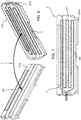
Figure 6 shows a perspective view of a further possible embodiment of a panel according to the invention; and -
Figure 7 shows a front view of the embodiment infigure 6 . - The
reference number 1 indicates a vehicle as a whole, in the non-limiting example illustrated herein a Light Commercial Vehicle, LCV, comprising, as is known, a frame (not shown for simplicity) and a plurality ofpanels 2 defining the body of thesaid vehicle 1. - The
vehicle 1 also comprises at least one air-bag system 3 of a known type and configured to expand and cushion impacts that may potentially cause damage to the driver or passenger. - The
vehicle 1 further comprises an electronic unit 4 configured to control a plurality of vehicle systems, including the above-mentioned air-bag system 3 and functional elements, not shown and configured to allow the operation of the vehicle, such as high voltage electrical equipment parts or control valves connected to the alternative fuel supply and distribution systems on board the vehicle. -
Figure 2 shows apanel 2 according to a first embodiment of the invention comprising a body defining any substantially flat shape, i.e., with two dimensions much larger than the thickness of the said body. In the simplified figure, a parallelepiped portion is shown, for example, a body portion made of any shape and material, for example plastic. - According to the invention, the
panel 2 comprises afilament 5 made of electrically conductive material carried by thepanel 2 and configured to break in case of impact and fracture of thepanel 2. - Advantageously, the
filament 5 made of electrically conductive material is incorporated inside the body of thepanel 2 so that it is not exposed to atmospheric agents and possible mechanical wear or abrasion. Even more advantageously, it is embedded in a plane corresponding to a neutral centre plane of thepanel 2. Neutral plane, as is known, refers to the plane in which the bending stresses on thepanel 2 are the lowest (theoretically zero) with respect to a bending load imparted thereon. - Still preferably, the
filament 5 made of electrically conductive material enters through afirst opening 6 inside the body of thepanel 2 and exits therefrom through anopening 7 formed therein. - Advantageously, the
filament 5 made of electrically conductive material defines a path along thepanel 2 so that it extends by at least twice the largest dimension of thepanel 2. - In particular, the
filament 5 made of electrically conductive material defines a path extending far beyond twice the largest dimension of thepanel 2, thereby providing a complex path to cover most of the surface defined by thepanel 2. - Again, according to the described embodiment, the
filament 5 made of electrically conductive material defines a plurality of coils 5a parallel to the larger side of thepanel 2. - According to the preferred embodiment shown herein, the plurality of coils 5a is embedded within the
panel 2 between thefirst opening 6 and thesecond opening 7, which are positioned one below the other, respectively, and formed on the smaller edge of thepanel 2. In this way, the path of thefilament 5 made of electrically conductive material inside thepanel 2 defines a "fork" shape due to the plurality of coils 5a connected, at one end and at the other, to theopenings - As is obvious, the
panel 2 also comprises connection means 8, here shown asholes 9, configured to allow thepanel 2 to be connected to an element carried by the frame of thevehicle 1, for example by means of rivets or threaded elements. Obviously, such connection means 8 can be of any type, such as form-fit or snap-fit couplings. - The second embodiment of the
panel 2 of the present invention, shown inFigure 2 , comprises the same elements as shown above inFigure 1 . - However, in this case, the body of the
panel 2 defines at least one portion of reduced thickness 2a. In the exemplary embodiment shown, this portion of reduced thickness 2a is a single, circular portion located at the geometric centre of thepanel 2. - The
filament 5 made of electrically conductive material is also electrically connected to the electronic unit 4 and/or to the above-mentioned functional elements, i.e., for example, the high voltage electrical equipment parts or the control valves connected to the alternative fuel system. Advantageously, this electrical connection is made physically through an electrical connection outside thepanel 2. - The operation of the embodiment of the
panel 2 described above is as follows. - In the event of an impact without any breakage of one of the
panels 2, no change in the electrical resistance in theelectric filaments 5 will be detected. However, the electronic unit 4, if necessary, can activate the air-bag system 3. - In the event of an impact with the breakage of one or
more panels 2, the resistance of thefilament 5 made of electrically conductive material will change, since the breakage of thepanel 2 provides for the opening of the electric circuit formed by thefilament 5 made of electrically conductive material and by the electronic unit 4 and/or the high voltage electrical equipment parts or the alternative fuel supply control valves. This change in electrical resistance will be processed by the electronic unit 4 to functionally insulate the electrical equipment parts or to insulate the alternative fuel flows. If the electrical connection is made directly by the electric filament with the functional elements of the vehicle, then this change in resistance will directly cause the insulation of the related potentially dangerous element. -
Figures 4 and 5 show a possible embodiment of apanel 2 according to the principles described above. - In
Figures 4 and 5 , thepanel 2 comprises abody 101, and acover 102 configured to wrap thebody 101 and therefore having a shape such as to be form-fit coupled and fixed thereto in a known manner. Thecover 102 can be made of high-density polyethylene or other plastic material with similar physical characteristics, and thebody 101 can be made of expanded polypropylene (EPP). - The
body 101 is configured to define aseat 103 suitable to house thefilament 5 made of electrically conductive material. In the example shown, theseat 103 is substantially rectangular and formed in the centre of thebody 101. When thecover 102 is coupled to thebody 101, theseat 103 is obviously insulated with respect to the external environment. - In the illustrated embodiment, the
filament 5 is made as a resistive-coated printed circuit board (PCB) 104 comprising aconnector 105 configured to keep two input and output portions 104', 104'' of theprinted circuit board 104 separated and to connect them to the electronic unit 4 and/or to the above-mentioned functional elements. - In particular, the printed
circuit board 104 may comprise portions of reduced thickness, or cuts, (not clearly shown) configured to facilitate the breaking of the printedcircuit board 104 in the event of an impact. -
Figures 6 and 7 show a further embodiment of apanel 2 according to the principles described above. - In
Figures 6 and 7 , thepanel 2 comprises a single pair ofelements 202 made of high-density polyethylene, for example. - Each
element 201 is configured to define afirst face 201a and asecond face 201b opposite the first, therefore aface 201a facing outwards and aface 201b facing the inside of the vehicle. In particular, the twoelements 201 are configured to be coupled on top of each other so that theinner face 201b of one element cooperates in contact with theouter face 201a of the other. - In the illustrated embodiment, the
filament 5 is made by deposition of electricallyconductive paint 202 on one of thefaces inner face 201b of one of theelements 201. - The operation of the embodiments described in
Figures 4,5 and6, 7 is similar to that described above forFigures 2 and 3 and will not be repeated for the sake of brevity. - The advantages of a
panel 2 according to the invention are clear from the foregoing. - The system of the
sensorized panel 2 according to the invention allows the insulation of dangerous functional elements of thevehicle 1 to be released from the deployment of the air-bag system 3 of the vehicle. - In particular, it is possible to provide
panels 2 in the most sensitive points of the vehicle exposed to impacts which can cause exposure of the dangerous functional elements of the vehicle. - Moreover, the system set out herein is particularly cost-effective and does not substantially increase the overall dimensions either outside or inside the
vehicle 1. An effective example of this reduction is the use of an electrically conductive paint layer to define thefilament 5. - It is also possible to create a break in the
panel 2 localized in the most critical points of the panel with respect to the exposure of the functional elements of thevehicle 1. An effective example of such localized breaks can be obtained, as illustrated, by reductions in the thickness of the body of thepanel 2 or of the elements forming it, or by smaller portions in thefilament 5. - Lastly, it is clear that modifications and variations may be made to the
panel 2 according to the present invention, without however departing from the scope of protection defined by the claims. - For example, it is clear that the
filament 5 can be arranged in any way on thepanel 2, or inside it, which can define different shapes and be made of different materials. - Furthermore, it is clear that the reduced-thickness portion 2a can be of a shape and number different from those described, just like the connection of the filament to the electronic unit 4 and/or to the functional elements of the
vehicle 1. - Finally, it is clear that the shape defined by the body of the
panel 2 and its position on thevehicle 1 can be any shape and position.
Claims (12)
- A panel (2) configured to cover a portion of a vehicle (1), said panel (2) comprising at least one body (101, 102; 202) configured to be connected to a portion that is fixed with respect to a frame of said vehicle (1), said panel (2) comprising a filament (5) of electrically conductive material configured to be electrically connected to a functional element of said vehicle (1).
- The panel according to claim 1, wherein said filament (5) is incorporated inside said body (101, 102) of said panel (2).
- The panel according to claim 1 or 2, wherein said filament (5) is placed in the neutral plane of said panel (2) .
- The panel according to one of the preceding claims, wherein the at least one body (102) of said panel (2) defines at least one portion (2a) of reduced thickness with respect to the remaining portion of said body (102).
- The panel according to one of the preceding claims, wherein said filament (5) is made of metal material.
- The panel according to one of the preceding claims, wherein said filament (5) defines a path with respect to said panel body (2), said path extending with respect to said body over most of the surface defined thereby.
- The panel according to one of the preceding claims, wherein said filament (5) defines a path with respect to said panel body (2), said path extending by at least twice the largest dimension of said body in space.
- The panel according to one of the preceding claims, wherein said filament (5) comprises a printed circuit board (104) .
- The panel according to one of the preceding claims, wherein said filament (5) is made by deposition of electrically conductive paint (202).
- The panel according to one of the preceding claims, wherein said filament (5) comprises portions of reduced thickness with respect to other remaining portions of said filament (5).
- A vehicle (1) comprising at least one panel (2) according to one of the preceding claims and functional elements electrically connected to said filament (5) so that a breakage of said filament (5) causes the functional insulation of said elements.
- The vehicle (1) according to claim 11, comprising an electronic unit (4) electrically connected to said filament (5) so that the detection of a breakage of said filament (5) is processed by said electronic unit (4) to control said functional elements so as to functionally insulate them.
Applications Claiming Priority (1)
| Application Number | Priority Date | Filing Date | Title |
|---|---|---|---|
| IT102020000005779A IT202000005779A1 (en) | 2020-03-18 | 2020-03-18 | SENSORIZED PANEL FOR IMPACT DETECTION IN A VEHICLE |
Publications (3)
| Publication Number | Publication Date |
|---|---|
| EP3882086A1 true EP3882086A1 (en) | 2021-09-22 |
| EP3882086B1 EP3882086B1 (en) | 2024-12-18 |
| EP3882086C0 EP3882086C0 (en) | 2024-12-18 |
Family
ID=70805076
Family Applications (1)
| Application Number | Title | Priority Date | Filing Date |
|---|---|---|---|
| EP21163546.1A Active EP3882086B1 (en) | 2020-03-18 | 2021-03-18 | Sensorized panel for detection of an impact on a vehicle |
Country Status (3)
| Country | Link |
|---|---|
| EP (1) | EP3882086B1 (en) |
| ES (1) | ES3010353T3 (en) |
| IT (1) | IT202000005779A1 (en) |
Cited By (2)
| Publication number | Priority date | Publication date | Assignee | Title |
|---|---|---|---|---|
| EP4461583A1 (en) * | 2023-05-12 | 2024-11-13 | Daimler Truck AG | Device and method for performing an emergency deactivation of a high-voltage system of an electrically driven vehicle |
| EP4464536A1 (en) * | 2023-05-19 | 2024-11-20 | DAF Trucks N.V. | Skirt assembly for a bev truck |
Citations (5)
| Publication number | Priority date | Publication date | Assignee | Title |
|---|---|---|---|---|
| EP1698453A1 (en) * | 2005-03-04 | 2006-09-06 | Nippon Sheet Glass Company, Limited | Panel |
| WO2010042848A1 (en) * | 2008-10-09 | 2010-04-15 | Adc Telecommunications, Inc. | Power switching arrangement |
| WO2010136863A1 (en) * | 2009-05-26 | 2010-12-02 | Nissan Motor Co., Ltd. | Vehicle battery cooling structure |
| EP2360061A1 (en) * | 2008-11-21 | 2011-08-24 | Hitachi, Ltd. | Functional panel and method for joining same |
| DE102015201440A1 (en) * | 2015-01-28 | 2016-07-28 | Bayerische Motoren Werke Aktiengesellschaft | Supply rail for a motor vehicle |
-
2020
- 2020-03-18 IT IT102020000005779A patent/IT202000005779A1/en unknown
-
2021
- 2021-03-18 EP EP21163546.1A patent/EP3882086B1/en active Active
- 2021-03-18 ES ES21163546T patent/ES3010353T3/en active Active
Patent Citations (5)
| Publication number | Priority date | Publication date | Assignee | Title |
|---|---|---|---|---|
| EP1698453A1 (en) * | 2005-03-04 | 2006-09-06 | Nippon Sheet Glass Company, Limited | Panel |
| WO2010042848A1 (en) * | 2008-10-09 | 2010-04-15 | Adc Telecommunications, Inc. | Power switching arrangement |
| EP2360061A1 (en) * | 2008-11-21 | 2011-08-24 | Hitachi, Ltd. | Functional panel and method for joining same |
| WO2010136863A1 (en) * | 2009-05-26 | 2010-12-02 | Nissan Motor Co., Ltd. | Vehicle battery cooling structure |
| DE102015201440A1 (en) * | 2015-01-28 | 2016-07-28 | Bayerische Motoren Werke Aktiengesellschaft | Supply rail for a motor vehicle |
Cited By (3)
| Publication number | Priority date | Publication date | Assignee | Title |
|---|---|---|---|---|
| EP4461583A1 (en) * | 2023-05-12 | 2024-11-13 | Daimler Truck AG | Device and method for performing an emergency deactivation of a high-voltage system of an electrically driven vehicle |
| EP4464536A1 (en) * | 2023-05-19 | 2024-11-20 | DAF Trucks N.V. | Skirt assembly for a bev truck |
| NL2034865B1 (en) * | 2023-05-19 | 2024-12-03 | Daf Trucks Nv | Skirt assembly for a BEV truck |
Also Published As
| Publication number | Publication date |
|---|---|
| ES3010353T3 (en) | 2025-04-02 |
| EP3882086B1 (en) | 2024-12-18 |
| EP3882086C0 (en) | 2024-12-18 |
| IT202000005779A1 (en) | 2021-09-18 |
Similar Documents
| Publication | Publication Date | Title |
|---|---|---|
| US20210233729A1 (en) | Electrical circuit breaker | |
| EP1645475B1 (en) | Power supply apparatus for vehicle | |
| US6225610B1 (en) | Use of PTC devices to protect insulated wires in electrical harnesses | |
| EP3882086B1 (en) | Sensorized panel for detection of an impact on a vehicle | |
| EP0638458B1 (en) | An electric system of an electric vehicle | |
| US20150109746A1 (en) | Electronic control device including interrupt wire | |
| JP5841898B2 (en) | On-vehicle electronic device and vehicle equipped with the same | |
| EP2993681B1 (en) | Mechanical disconnect switch with integrated fuse protection | |
| US10964484B2 (en) | On-vehicle circuit unit | |
| US7053298B2 (en) | Electric connecting box | |
| US9490094B2 (en) | Overcurrent protection apparatus | |
| EP0745515B1 (en) | A circuit protecting device for an automotive wiring harness | |
| US7495880B2 (en) | Circuit board and electric device having circuit board | |
| KR102361583B1 (en) | Block for vehicle | |
| US10938142B2 (en) | Electrical connection box | |
| EP3509168B1 (en) | Rotary connector device | |
| EP3671801A1 (en) | Sealed battery fuse module with energy dissipating cap | |
| US6729907B1 (en) | Plug-in connector for an electrical device | |
| JPH08190809A (en) | Wire with fuse | |
| JP2005317408A (en) | Fuel cell | |
| JP7785043B2 (en) | Energy storage pack | |
| KR102730547B1 (en) | Battery pack capable of shutting down relay on impact | |
| KR102892526B1 (en) | Pyrofuse | |
| KR100223470B1 (en) | Multi-directional shock sensor | |
| CN119365955A (en) | Replaceable overcurrent protection device, fuse box and vehicle for protecting current circuit |
Legal Events
| Date | Code | Title | Description |
|---|---|---|---|
| PUAI | Public reference made under article 153(3) epc to a published international application that has entered the european phase |
Free format text: ORIGINAL CODE: 0009012 |
|
| STAA | Information on the status of an ep patent application or granted ep patent |
Free format text: STATUS: THE APPLICATION HAS BEEN PUBLISHED |
|
| AK | Designated contracting states |
Kind code of ref document: A1 Designated state(s): AL AT BE BG CH CY CZ DE DK EE ES FI FR GB GR HR HU IE IS IT LI LT LU LV MC MK MT NL NO PL PT RO RS SE SI SK SM TR |
|
| STAA | Information on the status of an ep patent application or granted ep patent |
Free format text: STATUS: REQUEST FOR EXAMINATION WAS MADE |
|
| 17P | Request for examination filed |
Effective date: 20220316 |
|
| RBV | Designated contracting states (corrected) |
Designated state(s): AL AT BE BG CH CY CZ DE DK EE ES FI FR GB GR HR HU IE IS IT LI LT LU LV MC MK MT NL NO PL PT RO RS SE SI SK SM TR |
|
| STAA | Information on the status of an ep patent application or granted ep patent |
Free format text: STATUS: EXAMINATION IS IN PROGRESS |
|
| 17Q | First examination report despatched |
Effective date: 20230411 |
|
| GRAP | Despatch of communication of intention to grant a patent |
Free format text: ORIGINAL CODE: EPIDOSNIGR1 |
|
| STAA | Information on the status of an ep patent application or granted ep patent |
Free format text: STATUS: GRANT OF PATENT IS INTENDED |
|
| INTG | Intention to grant announced |
Effective date: 20240715 |
|
| GRAS | Grant fee paid |
Free format text: ORIGINAL CODE: EPIDOSNIGR3 |
|
| GRAA | (expected) grant |
Free format text: ORIGINAL CODE: 0009210 |
|
| STAA | Information on the status of an ep patent application or granted ep patent |
Free format text: STATUS: THE PATENT HAS BEEN GRANTED |
|
| AK | Designated contracting states |
Kind code of ref document: B1 Designated state(s): AL AT BE BG CH CY CZ DE DK EE ES FI FR GB GR HR HU IE IS IT LI LT LU LV MC MK MT NL NO PL PT RO RS SE SI SK SM TR |
|
| REG | Reference to a national code |
Ref country code: CH Ref legal event code: EP |
|
| REG | Reference to a national code |
Ref country code: DE Ref legal event code: R096 Ref document number: 602021023419 Country of ref document: DE |
|
| REG | Reference to a national code |
Ref country code: IE Ref legal event code: FG4D |
|
| U01 | Request for unitary effect filed |
Effective date: 20241230 |
|
| U07 | Unitary effect registered |
Designated state(s): AT BE BG DE DK EE FI FR IT LT LU LV MT NL PT RO SE SI Effective date: 20250114 |
|
| REG | Reference to a national code |
Ref country code: ES Ref legal event code: FG2A Ref document number: 3010353 Country of ref document: ES Kind code of ref document: T3 Effective date: 20250402 |
|
| PG25 | Lapsed in a contracting state [announced via postgrant information from national office to epo] |
Ref country code: HR Free format text: LAPSE BECAUSE OF FAILURE TO SUBMIT A TRANSLATION OF THE DESCRIPTION OR TO PAY THE FEE WITHIN THE PRESCRIBED TIME-LIMIT Effective date: 20241218 |
|
| U20 | Renewal fee for the european patent with unitary effect paid |
Year of fee payment: 5 Effective date: 20250311 |
|
| PG25 | Lapsed in a contracting state [announced via postgrant information from national office to epo] |
Ref country code: NO Free format text: LAPSE BECAUSE OF FAILURE TO SUBMIT A TRANSLATION OF THE DESCRIPTION OR TO PAY THE FEE WITHIN THE PRESCRIBED TIME-LIMIT Effective date: 20250318 |
|
| PG25 | Lapsed in a contracting state [announced via postgrant information from national office to epo] |
Ref country code: GR Free format text: LAPSE BECAUSE OF FAILURE TO SUBMIT A TRANSLATION OF THE DESCRIPTION OR TO PAY THE FEE WITHIN THE PRESCRIBED TIME-LIMIT Effective date: 20250319 |
|
| PG25 | Lapsed in a contracting state [announced via postgrant information from national office to epo] |
Ref country code: RS Free format text: LAPSE BECAUSE OF FAILURE TO SUBMIT A TRANSLATION OF THE DESCRIPTION OR TO PAY THE FEE WITHIN THE PRESCRIBED TIME-LIMIT Effective date: 20250318 |
|
| PG25 | Lapsed in a contracting state [announced via postgrant information from national office to epo] |
Ref country code: SM Free format text: LAPSE BECAUSE OF FAILURE TO SUBMIT A TRANSLATION OF THE DESCRIPTION OR TO PAY THE FEE WITHIN THE PRESCRIBED TIME-LIMIT Effective date: 20241218 |
|
| PG25 | Lapsed in a contracting state [announced via postgrant information from national office to epo] |
Ref country code: PL Free format text: LAPSE BECAUSE OF FAILURE TO SUBMIT A TRANSLATION OF THE DESCRIPTION OR TO PAY THE FEE WITHIN THE PRESCRIBED TIME-LIMIT Effective date: 20241218 |
|
| PGFP | Annual fee paid to national office [announced via postgrant information from national office to epo] |
Ref country code: ES Payment date: 20250417 Year of fee payment: 5 |
|
| PG25 | Lapsed in a contracting state [announced via postgrant information from national office to epo] |
Ref country code: IS Free format text: LAPSE BECAUSE OF FAILURE TO SUBMIT A TRANSLATION OF THE DESCRIPTION OR TO PAY THE FEE WITHIN THE PRESCRIBED TIME-LIMIT Effective date: 20250418 |
|
| PG25 | Lapsed in a contracting state [announced via postgrant information from national office to epo] |
Ref country code: SK Free format text: LAPSE BECAUSE OF FAILURE TO SUBMIT A TRANSLATION OF THE DESCRIPTION OR TO PAY THE FEE WITHIN THE PRESCRIBED TIME-LIMIT Effective date: 20241218 |
|
| PG25 | Lapsed in a contracting state [announced via postgrant information from national office to epo] |
Ref country code: CZ Free format text: LAPSE BECAUSE OF FAILURE TO SUBMIT A TRANSLATION OF THE DESCRIPTION OR TO PAY THE FEE WITHIN THE PRESCRIBED TIME-LIMIT Effective date: 20241218 |
|
| PG25 | Lapsed in a contracting state [announced via postgrant information from national office to epo] |
Ref country code: MC Free format text: LAPSE BECAUSE OF FAILURE TO SUBMIT A TRANSLATION OF THE DESCRIPTION OR TO PAY THE FEE WITHIN THE PRESCRIBED TIME-LIMIT Effective date: 20241218 |
|
| PLBE | No opposition filed within time limit |
Free format text: ORIGINAL CODE: 0009261 |
|
| REG | Reference to a national code |
Ref country code: CH Ref legal event code: H13 Free format text: ST27 STATUS EVENT CODE: U-0-0-H10-H13 (AS PROVIDED BY THE NATIONAL OFFICE) Effective date: 20251024 |
|
| STAA | Information on the status of an ep patent application or granted ep patent |
Free format text: STATUS: NO OPPOSITION FILED WITHIN TIME LIMIT |
|
| 26N | No opposition filed |
Effective date: 20250919 |
|
| GBPC | Gb: european patent ceased through non-payment of renewal fee |
Effective date: 20250318 |
|
| PG25 | Lapsed in a contracting state [announced via postgrant information from national office to epo] |
Ref country code: GB Free format text: LAPSE BECAUSE OF NON-PAYMENT OF DUE FEES Effective date: 20250318 |
|
| PG25 | Lapsed in a contracting state [announced via postgrant information from national office to epo] |
Ref country code: CH Free format text: LAPSE BECAUSE OF NON-PAYMENT OF DUE FEES Effective date: 20250331 |
|
| PG25 | Lapsed in a contracting state [announced via postgrant information from national office to epo] |
Ref country code: IE Free format text: LAPSE BECAUSE OF NON-PAYMENT OF DUE FEES Effective date: 20250318 |
|
| U20 | Renewal fee for the european patent with unitary effect paid |
Year of fee payment: 6 Effective date: 20260203 |